1. Introduction
For decades, seismic engineering focused on enhancing the seismic performance of building structures, particularly those in high-intensity seismic zones and those that are strategically important. Traditional seismic design methods have become inadequate to meet modern engineering demands, while hybrid control technology has emerged as a research focus in structural vibration control due to its superior energy dissipation capacity and adaptability. Since the 20th century, frequent destructive earthquakes worldwide have provided valuable empirical data for seismic research. The 2008 Wenchuan earthquake (M8.0) caused widespread building collapse. Post-earthquake investigations revealed that reinforced concrete frames designed with the conventional “strong column–weak beam” principle, although avoiding complete collapse, predominantly exhibited “column hinge mechanisms” instead of the intended “beam hinge mechanisms”, resulting in difficult post-earthquake repairs [
1]. The 2011 Tohoku earthquake (M9.0) further prompted a critical reassessment of structural performance beyond design basis seismic motions. Notably, some buildings employing passive control technology demonstrated remarkable vibration mitigation under long-period ground motions. These seismic events catalyzed a paradigm shift in earthquake-resistant design philosophy from “collapse prevention” to “functional recovery”. China’s Code for Seismic Design of Buildings (GB50011-2010) [
2] explicitly mandates that critical facilities (e.g., hospitals and emergency command centers) maintain either “immediate occupancy” or “rapid repairability” performance levels under rare earthquakes. However, conventional ductility design or localized strengthening measures alone have proven insufficient to achieve these objectives [
3,
4]. Consequently, structural vibration control technologies, particularly hybrid control strategies, have become promising solutions.
The “hybrid mass damping system” proposed by researchers has been successfully implemented in practical engineering applications, achieving over 40% reduction in structural acceleration responses under both strong winds and seismic excitations [
5]. Scholars developed a “force–displacement hybrid control method” specifically for large-stiffness multi-degree-of-freedom structures. Through the synchronized operation of shaking tables and hydraulic actuators, they resolved the long-standing challenge of stiffness simulation inaccuracy in conventional pseudo-dynamic testing. This methodology was validated through reinforced concrete core tube experiments, demonstrating less than 5% error and establishing a novel analytical approach for evaluating complex hybrid systems [
6]. Researchers also engineered various damping devices [
7,
8] and optimized dynamic damping systems, significantly enhancing control precision and robustness [
9,
10]. These systems underwent rigorous performance testing and validation in real-world applications. Through equivalent linearization methods, optimal high damping ratios were achieved [
11,
12], effectively decoupling the system’s internal mass from damping layer interactions [
13]. The rotational damping system implemented in structural designs demonstrated superior performance metrics (including 99.5% energy efficiency and dynamic behavior indicators, such as the peak rate and energy loss ratio) compared to those of existing technologies [
14]. Smart damping devices [
15] successfully realized solid-state reverse conversion characteristics and time–frequency balance. The FCM (friction control mechanism) exhibited exceptional performance in mitigating static jitter, periodic disturbances, and self-centering intensity attenuation, accomplishing high-strength objectives with compact dimensions [
16,
17]. These advancements collectively propelled the engineering application of hybrid control technologies. The hybrid passive control method of the Combined Viscous-Stiffness Damper System (CVSDS) explored time-frequency characteristics in the frequency domain through wavelet transform (WT) to achieve optimal vibration damping effects [
18,
19]. Based on the principle of multi-body kinematics and through the simplified elastoplastic analysis method, the implementation strategy for earthquake repair was redefined [
20,
21,
22].
In summary, researchers have conducted both experimental and theoretical investigations on the vibration control of non-proportionally damped structures. However, relatively limited studies have been devoted to hybrid control strategies for strategically important structures in high-intensity seismic zones with cold climates. In this study, comparative analyses between uncontrolled structures and non-proportionally damped structures are conducted. A computational method for equivalent damping ratios is proposed, and the modal characteristics, structural responses, and damage patterns of both uncontrolled and energy-dissipated structures are investigated under rare earthquake events. The findings provide valuable references for structural control applications in high-intensity seismic regions.
2. Coupled Analysis of Equivalent Damping and Dynamic Response for Time-Varying Hybrid Control Systems
Prior to the establishment of the theoretical framework for the hybrid control system incorporating viscous and magnetorheological (MR) dampers, it was considered essential that an intrinsic connection be established between the mathematical treatment methods and practical engineering problems. In this study, the governing equations for structures, which accounted for large deformation effects in the elastoplastic stage, were systematically derived. Furthermore, the control differential equations for the structural system were constructed. This provided a quantitative analysis tool for the collaborative working mechanism of the hybrid control system. Consequently, a solid theoretical foundation was laid for the optimal configuration of intelligent dampers and the design of control strategies, thereby ensuring the safety and reliability of complex engineering structures under extreme loads.
For an N-degree-of-freedom shear-type structural system, the equations of motion are established as follows:
The nonlinear damping force is expanded to the third order:
The state space enhanced representation is introduced:
The Hamiltonian function is constructed:
The total energy change rate of the system is
The frequency response operator is
The equivalent damping matrix is
The imaginary part is
where
Response of the hybrid control system in the elastoplastic stage
The deformation gradient tensor is
The Green–Lagrange strain tensor is
The component form of the Green–Lagrange strain tensor is
The nonlinear damping force of viscous dampers is
The Buc–Wen model of the damper is
The elastoplastic tangential modulus is
where
represents the elastic stiffness tensor (fourth order), which describes the stress–strain relationship of the material during the elastic stage.
represents the yield function, which is used to determine whether the material has undergone plastic deformation.
is the yield function corresponding to the gradient of the stress tensor, representing the direction of plastic flow (and also the direction of plastic strain increment in the associated flow rule).
represents the plastic modulus, which describes the hardening/softening behavior.
It is supposed that the material obeys the von Mises yield criterion, as follows:
where
Using equal-parameter elements, the interpolation of the displacement field and velocity field is
Within the time step t (n + 1), the K-th iteration is
where
3. Case Analysis
3.1. Project Overview
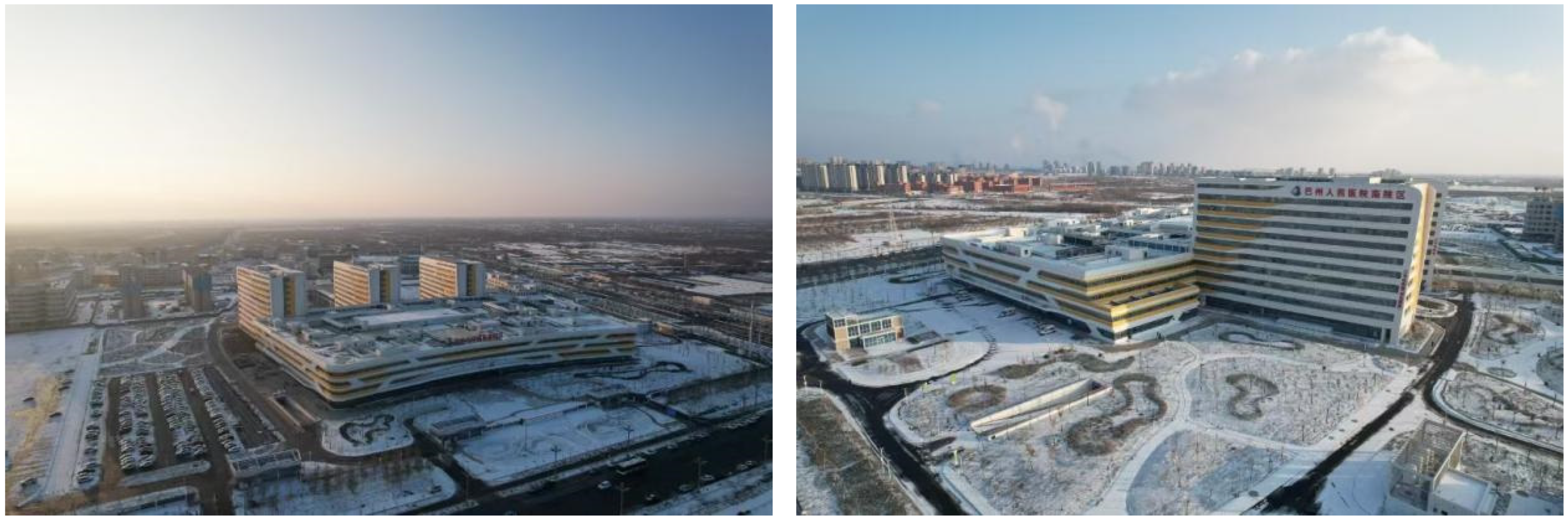
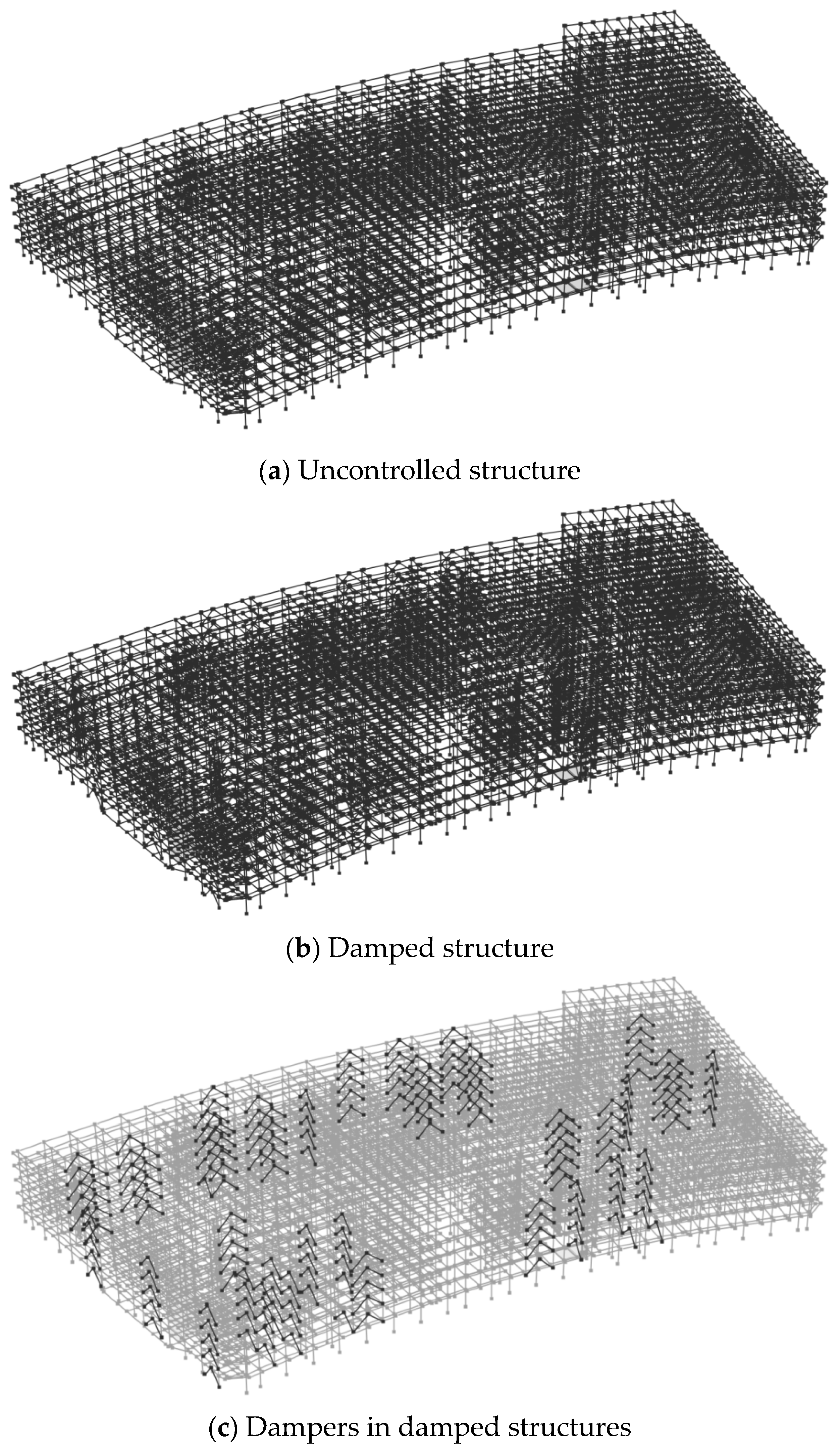
The site had a seismic fortification intensity of level 8 (0.2 g), with the second seismic grouping of a Category II site and a fundamental period (Tg) of 0.40 s. The seismic design classification was considered a key protection category (Category B). Seismic effects were evaluated based on level 8 (0.2 g), while seismic measures were designed considering level 9. The structural system was a cast-in-place reinforced concrete frame structure with viscous dampers (
Figure 1), 32 viscous dampers were installed in the X-axis direction, and 42 metal dampers were installed in the Y-axis direction. The types and parameters of the dampers are shown in
Table 1 and
Table 2, respectively. The damping ratios of the uncontrolled and damped structures were 5% and 10.50%, respectively. with the frame seismic fortification grade being level 1 and the shear wall seismic fortification grade also being level 1. The structure length was 231.00 m, the width was 109.80 m, the floor height was 5.7/4.5 m, and the overall building height was 19.20 m, as shown in
Figure 2. The damper parameters were detailed in
Table 1 and
Table 2. The above-ground structure had 4 floors (excluding the rooftop equipment room). The concrete materials used were C50, C45, C40, C35, and C30, and the reinforcement steel was HRB400. The frame beam cross-sectional dimensions were 450 mm × 900 mm, 400 mm × 800 mm, and 200 mm × 400 mm. The frame column cross-sectional dimensions were 650 mm × 900 mm, 600 mm × 800 mm, and 400 mm × 400 mm. The slab thicknesses were 120 mm and 100 mm. In the finite element model, geometric nonlinearity and material nonlinearity were considered. Plastic hinge models were used for the frame beams and columns, and a fiber section model was adopted for the shear walls.
In the analysis, a dynamic elastoplastic analysis was conducted using the Perform-3D V10.0 finite element software, with the dampers using connection elements. In the Perform-3D software, dampers are typically simulated using two-node connection elements (Two-Node Link Element) or zero-length elements (Zero-Length Element), the specific choice depending on the connection method and mechanical characteristics requirements of the dampers. In the elastoplastic time-history analysis, the dampers can work collaboratively with the structural framework through these elements to achieve energy dissipation and damping effects.
3.2. Seismic Waves
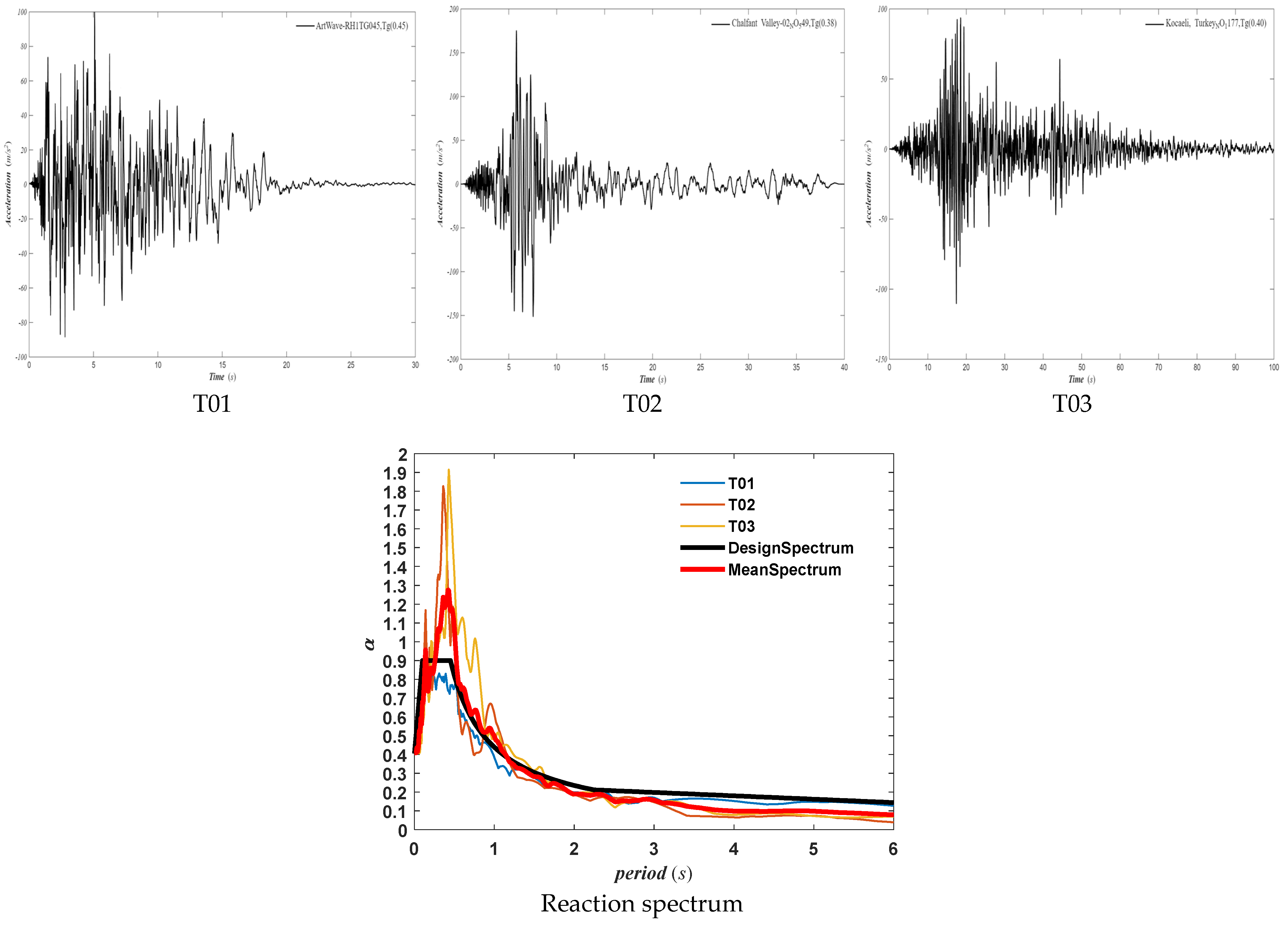
Referring to the seismic design code [
2,
23], three seismic waves (
Figure 3) were selected for a dynamic elastoplastic analysis of the unreinforced and damped structures. The peak acceleration was 400 cm/s
2, and the seismic input motions were scaled according to the ratio coefficient of X:Y:Z = 1:0.85:0.65.
3.3. Structural Modal Analysis
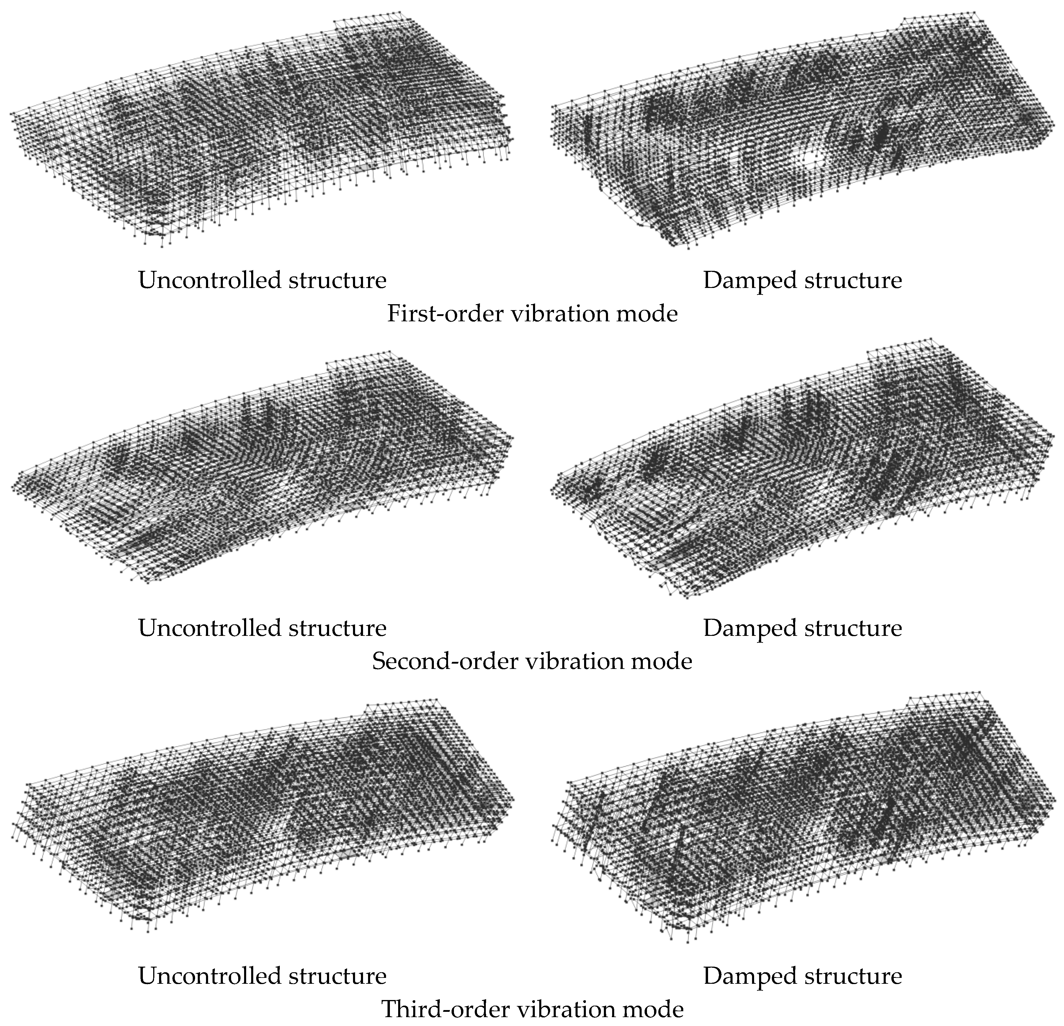
According to a modal analysis of the uncontrolled structure and damped structure, as shown in
Figure 4, the natural periods of the uncontrolled structure are 1.093 s, 1.027 s and 0.8626 s, the natural periods of the damped structure are 1.061 s, 1.010 s and 0.65 s. the mode shapes for the uncontrolled structure and damped structure were identified as translational modes in the X and Y directions and torsional modes. The structural vibration patterns were similar, with the ratios of the torsional mode to the translational mode are 0.79 and 0.61, respectively (
Table 3), which met the requirements of the relevant codes.
3.4. Comparison of Overall Structural Indicators
Through a dynamic elasto-plastic analysis, the overall performance indicators of the uncontrolled structure and the damped structure were compared. The effectiveness of the energy dissipation technology was thus quantitatively and intuitively verified. Furthermore, the working mechanism, whereby the structural response was reduced and the primary structural system was protected through the dissipation of energy, was profoundly revealed.
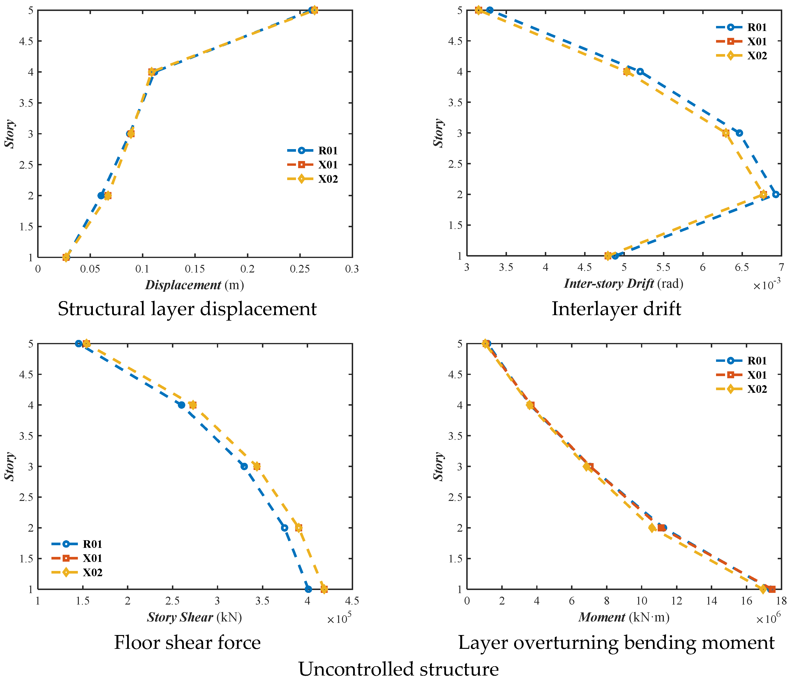
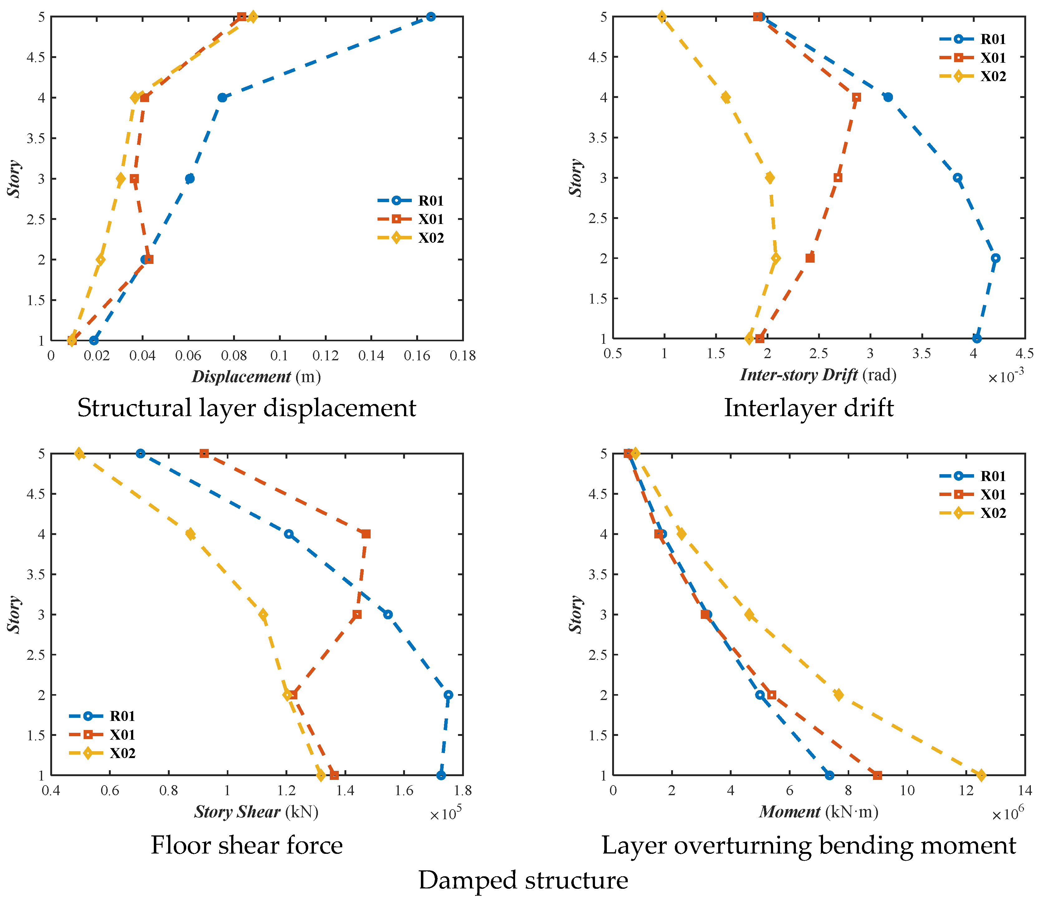
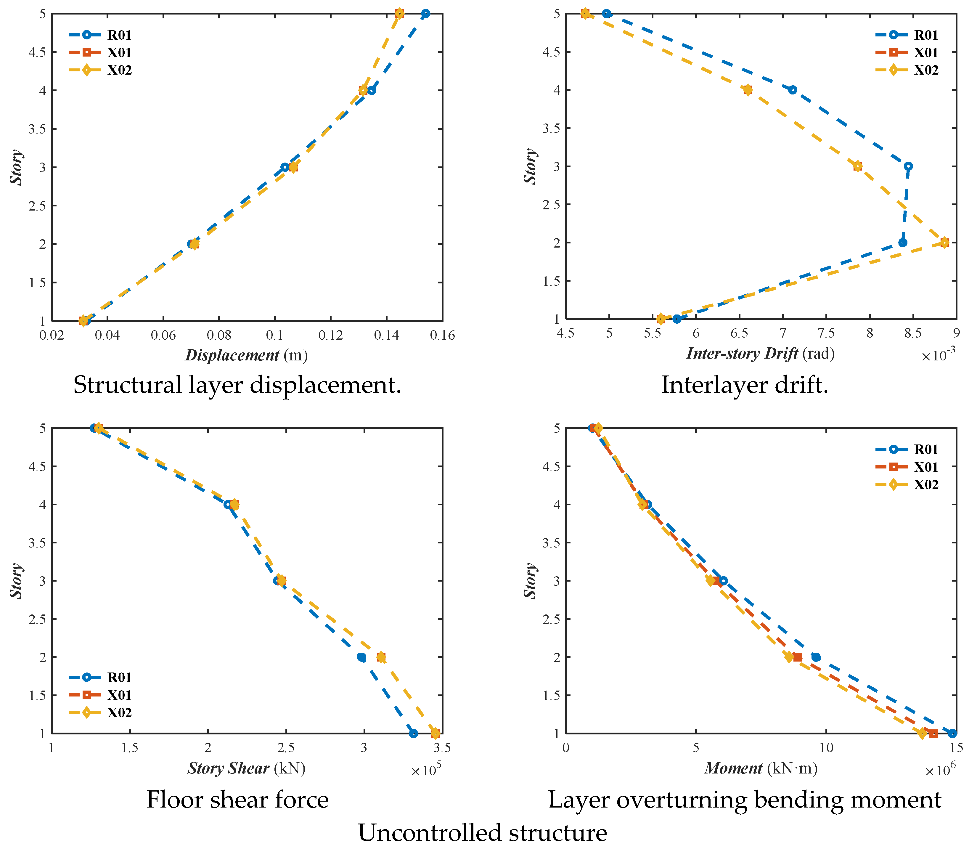
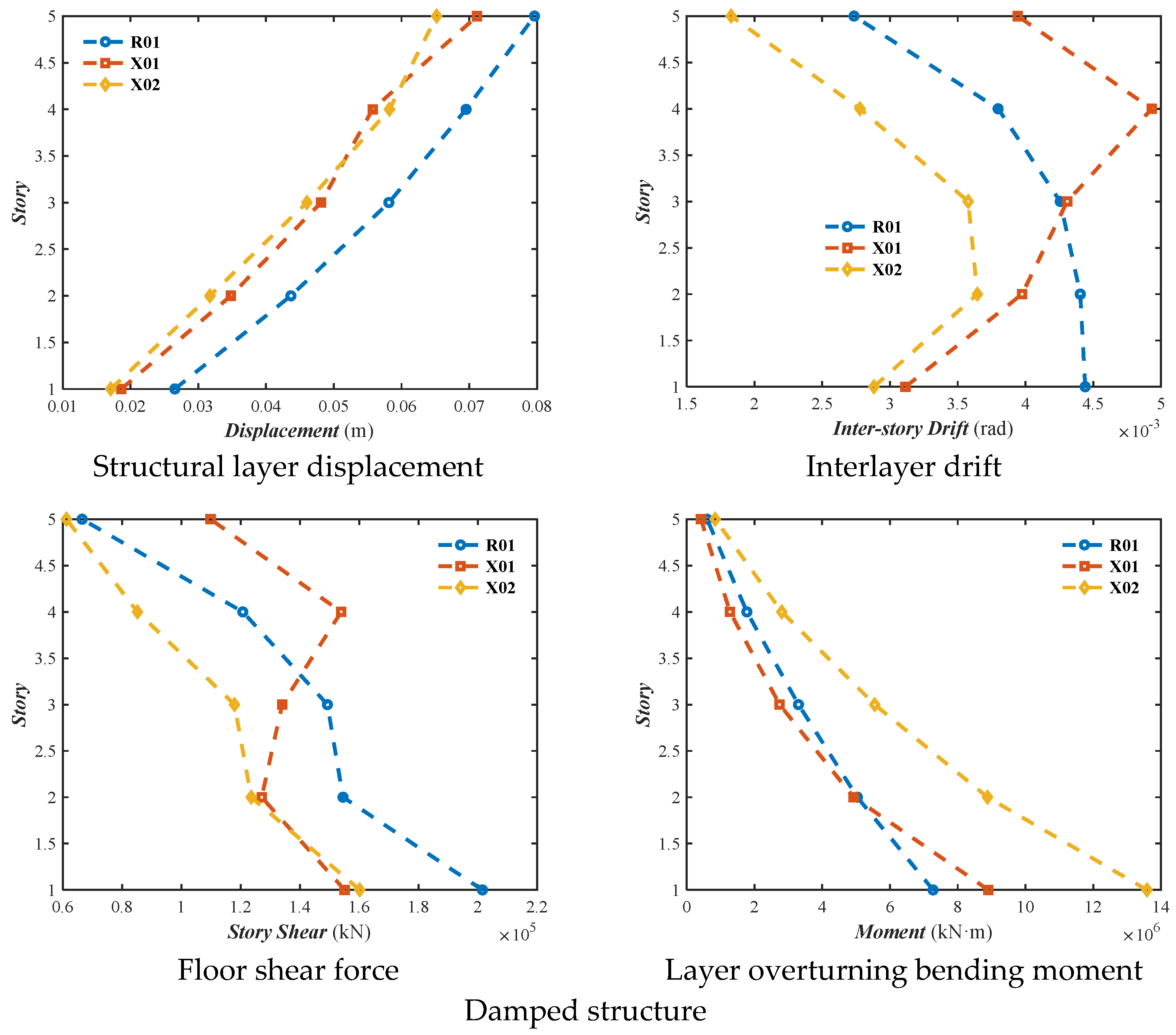
In the analysis result legend, R01, X01, and X02, respectively, represented the dynamic elastoplastic response results of the structure under the excitation of artificial wave 01, natural wave 01, and natural wave 02.
According to a comparative analysis of the overall indicators for the unreinforced and damped structures, as shown in
Figure 5, the displacement of the unreinforced structure in the X direction was 0.2639 m, the displacement angle was 0.0069 radians, the inter-story shear force was 418,684.5625 kN, and the inter-story bending moment was 17,468,468 kN·m. The damped structure’s displacement was 0.1660 m, the displacement angle was 0.0042 radians, the inter-story shear force was 172,598.9219 kN, and the inter-story bending moment was 12,516,883 kN·m. The displacement angles calculated for all three seismic motions were less than 1/50, satisfying the code requirements. The inter-story displacement reduction reached 37.09%, the shear force reduction was 58.78%, the bending moment reduction was 28.35%, and the displacement angle reduction was 39.16%. These results indicate that the hybrid control technology in the X direction significantly improved the structural dynamic response.
According to a comparative analysis of the overall indicators for the unreinforced and damped structures, as shown in
Figure 6, the Y-direction displacement of the unreinforced structure was 0.1540 m, the displacement angle was 0.0089 radians, the inter-story shear force was 345,588.5625 kN, and the inter-story bending moment was 14,838,435 kN·m. The damped structure’s displacement was 0.0796 m, the displacement angle was 0.0049 radians, the shear force was 201,595.2969 kN, and the bending moment was 13,584,687 kN·m. The inter-story displacement reduction reached 48.29%, the shear force reduction was 41.67%, the bending moment reduction was 8.45%, and the displacement angle reduction was 44.35%. The overall indicator comparison showed low data dispersion, and the displacement angles calculated for all three seismic motions were less than 1/50, satisfying the code requirements. These results indicate that the hybrid control technology in the Y direction significantly improved the structural dynamic response.
3.5. Structural Analysis Results
Seismic waves were applied to the structure in three directions, with X and Y as the primary directions, scaled according to a ratio of 1:0.85:0.65. A structural dynamic elastoplastic analysis was conducted under rare earthquake conditions.
3.5.1. Damage Distribution of Seismic Excitation Structures in the X Direction
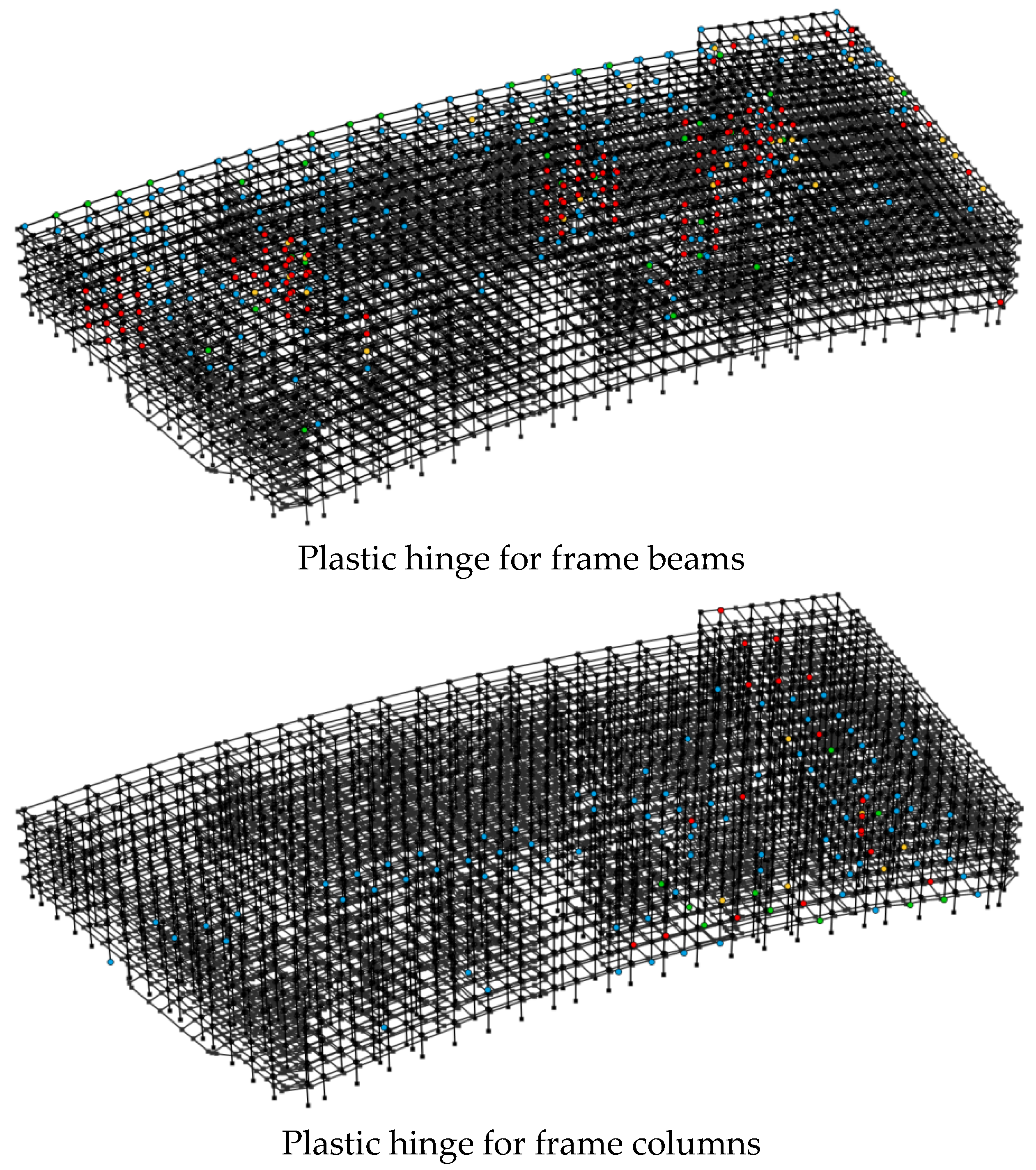
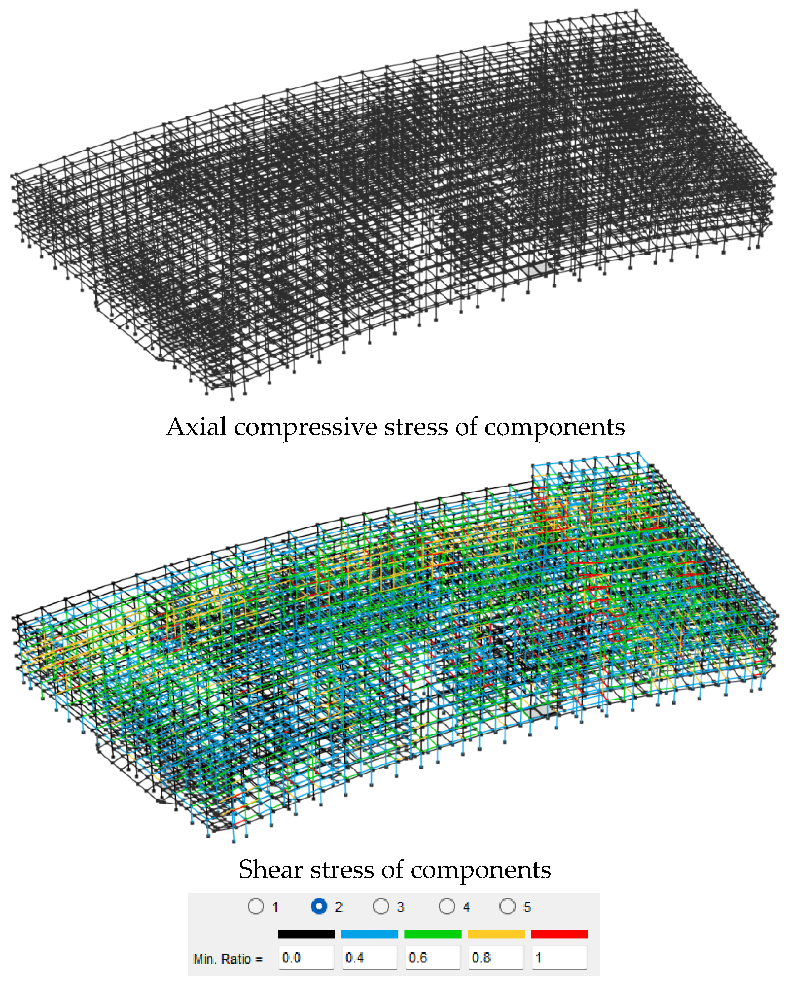
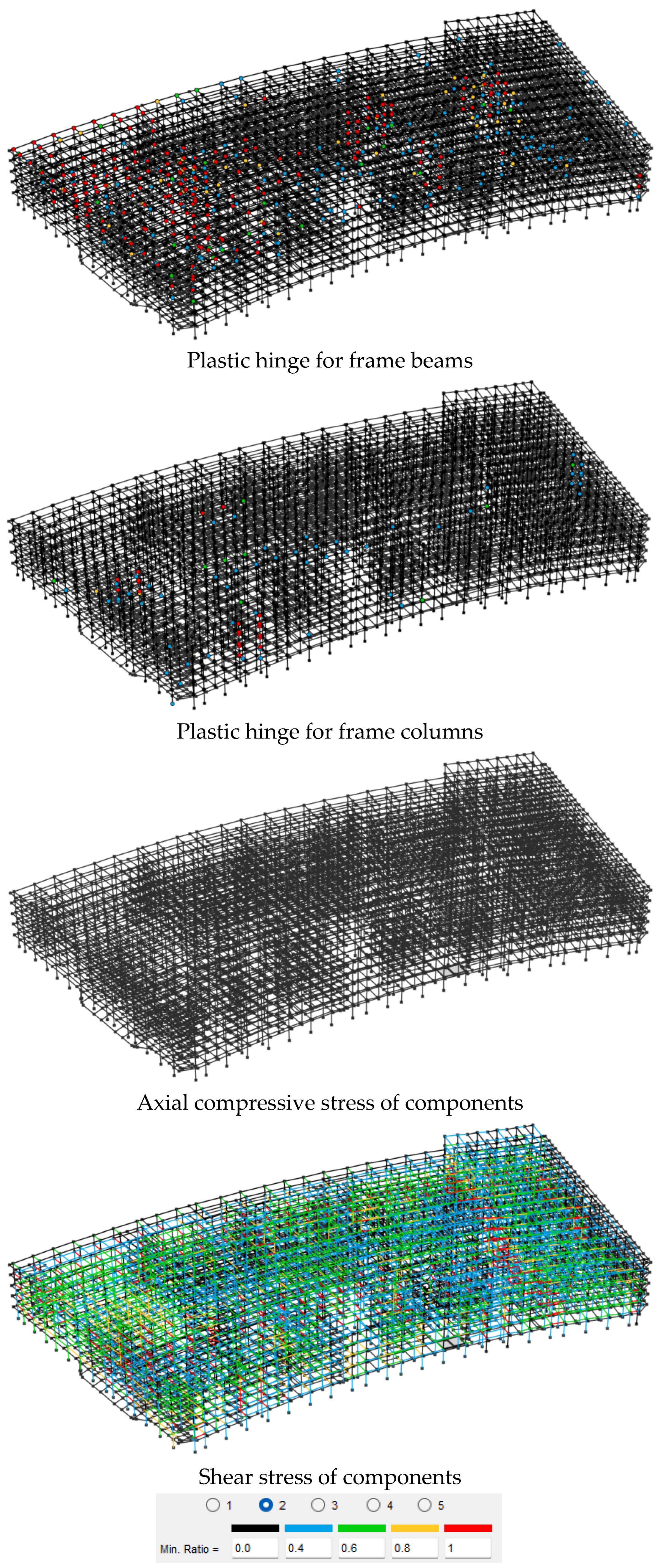
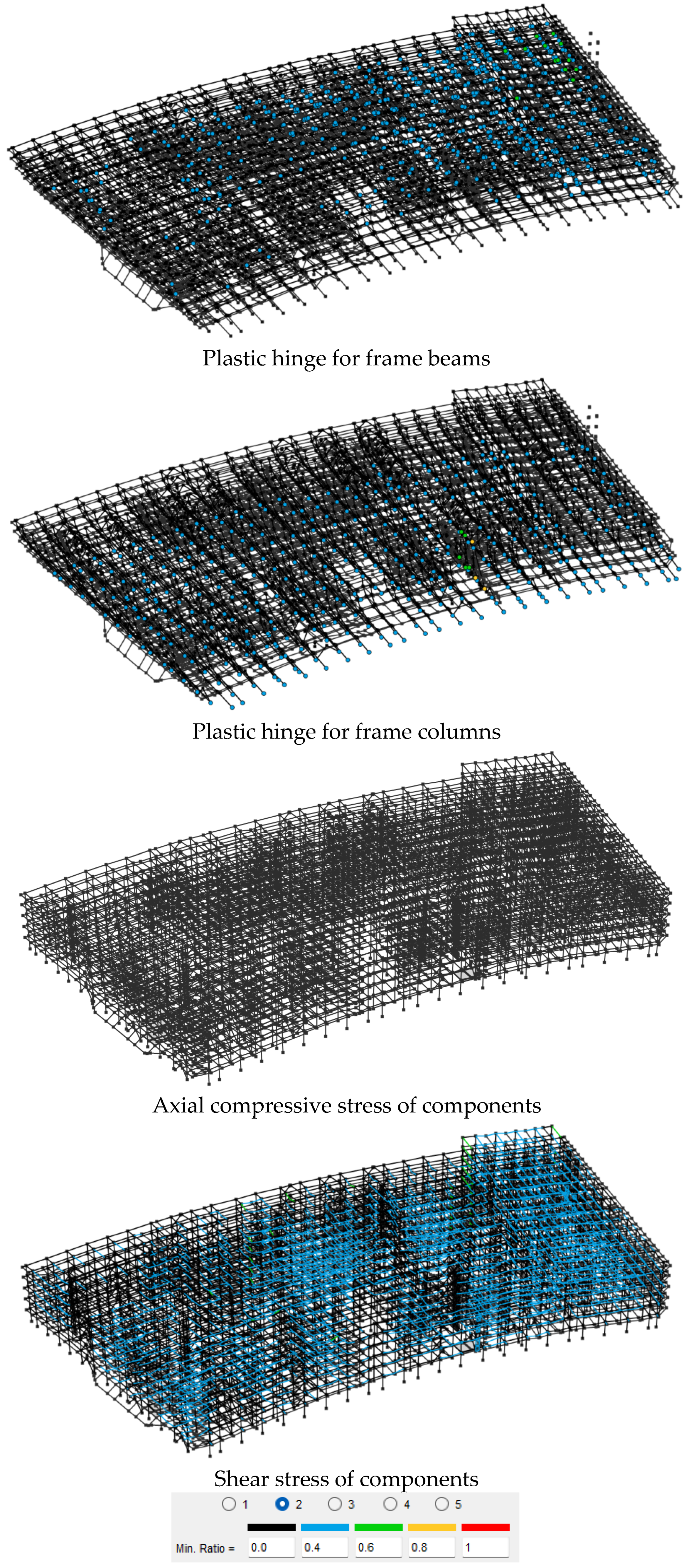
According to a comparative analysis of the damage indicator distributions for the unreinforced and damped structures, as shown in
Figure 7 and
Figure 8, the plastic hinge distribution in the frames of the uncontrolled structure was concentrated in the central regions, with higher damage levels in the upper-floor frame beams. The axial compressive strain of the members did not exceed the ultimate compressive strain, while the shear stress levels were relatively high, mainly concentrated in the upper regions. Compared to the unreinforced structure, the damped structure exhibited an overall improvement in damage levels, with lower degrees of plastic hinge damage in the frames, as well as reduced axial compressive strains and shear stress levels in the members.
3.5.2. Damage Distribution of Seismic Excitation Structures in the Y Direction
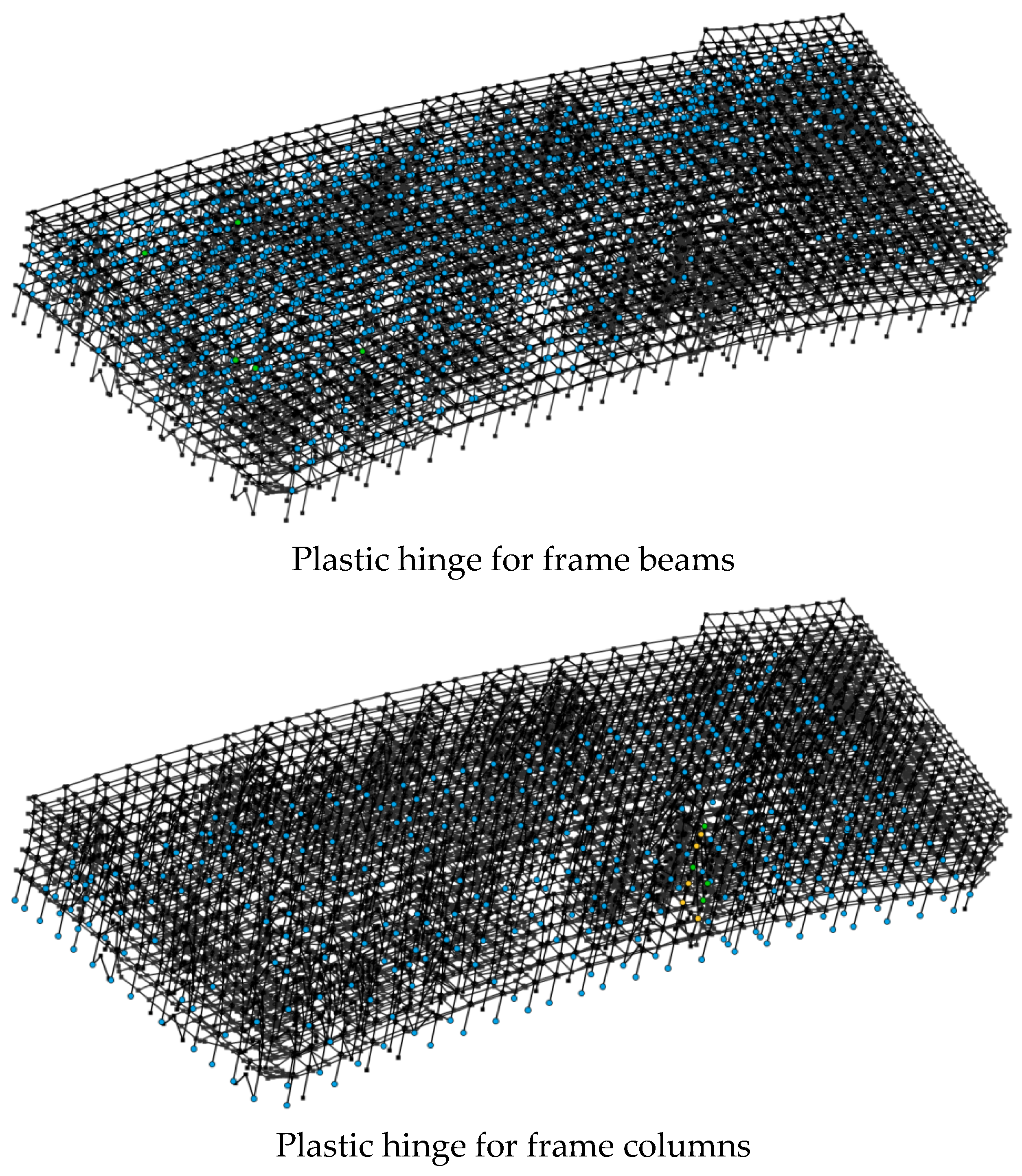
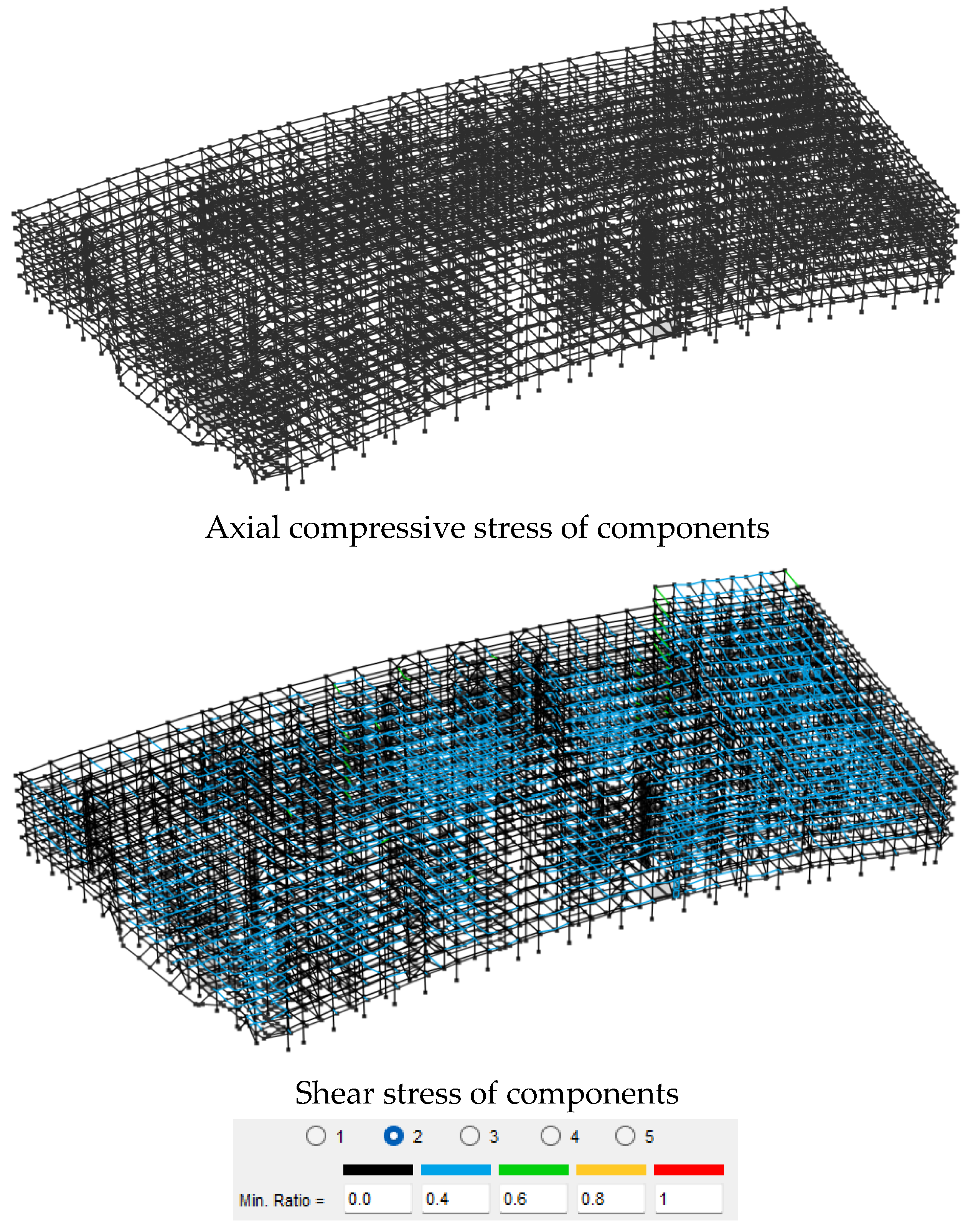
According to a comparative analysis of the damage indicator distributions for the unreinforced and damped structures, as shown in
Figure 9 and
Figure 10, the plastic hinge distribution in the unreinforced structure’s frames was concentrated in the left regions, with higher damage levels in the upper-floor frame beams. The axial compressive strain of the members did not exceed the ultimate compressive strain, while the shear stress levels in the middle regions were relatively high. Compared to the unreinforced structure, the damped structure showed an overall improvement in damage levels, with lower degrees of plastic hinge damage in the frames, as well as reduced axial compressive strains and shear stress levels, indicating that the plastic hinges in the frames were in a minor damage state. This improvement was attributed to the hybrid control system’s dissipation of seismic energy through the dampers, which reduced the internal forces within the main structure and optimized the stiffness distribution, thus shifting plastic hinges toward low-damage areas. Additionally, the velocity-dependent dampers effectively suppressed inter-story shear transfer, thereby decreasing axial strains and shear stresses.
4. Conclusions
The hybrid damping system significantly improved the dynamic response characteristics of the structure. By adopting a combined control scheme of “viscous dampers + metal composite dampers,” the first three natural periods of vibration were shortened by 6.1% (X-direction translation), 5.9% (Y-direction translation), and 21.0% (torsion), indicating that this system effectively enhanced the overall stiffness of the structure. Under seismic action in the X direction, the damped structure reduced inter-story displacements by 37.1% (from 0.264 m to 0.166 m) and improved inter-story displacement angles by 39.2% (from 1/144 to 1/237). The effects in the Y direction were even more pronounced, with a 48.3% reduction in inter-story displacement (from 0.154 m to 0.080 m) and a 44.4% decrease in inter-story displacement angles (from 1/113 to 1/203). The damping measures also had notable effects on base shear forces and bending moments, with the X-direction base shear decreasing by 58.8% and the Y-direction base shear decreasing by 41.7%.
The structure’s damage control achieved the targeted performance goals. A plastic hinge distribution analysis revealed that the damping measures significantly optimized the damage pattern. Compared to the dense plastic hinges at the beam ends observed in the unreinforced structure on the upper and middle floors, the damped structure only exhibited minor plastic hinges on the most unfavorable floors. Notably, the damping scheme maintained the axial compressive stress peaks in the frame columns within 0.65 fc, effectively avoiding crushing failure risks. A time–history analysis with three seismic waves demonstrated that the maximum inter-story drift angles were strictly controlled within the 1/50 limit, fulfilling the seismic design requirements for key protection buildings, as per GB50011-2010.
The hybrid damping system showed multi-dimensional seismic resilience advantages. The results indicate that the viscous dampers primarily reduced the vibration responses in the X direction, with their velocity-dependent characteristics effectively suppressing structural accelerations. Meanwhile, the metal composite dampers reduced displacements along the Y direction through yielding energy dissipation. This complementary effect maintained the difference in damping efficiency between the two main axes within 11%, significantly addressing the weak-axis problem that is common in conventional frame structures. Furthermore, reasonable damper placement decreased the torsional period of the structure by 21%, demonstrating that the hybrid system effectively balanced translational and torsional control needs.
The engineering application demonstrated great practical value and optimization potential. This project confirmed the technical feasibility of the “viscous damper + MR damper” hybrid scheme, which offers advantages such as cost-effectiveness, easy construction, and simple maintenance.
Author Contributions
Conceptualization, Y.J. and Q.L.; Methodology, J.W.; Validation, A.J.; Formal analysis, Y.J.; Investigation, A.J. and Y.W.; Resources, Q.L.; Data curation, J.W.; Writing—original draft, Y.J.; Writing—review and editing, J.W.; Visualization, A.J. and S.L.; Supervision, Q.L.; Project administration, Q.L.; Funding acquisition, Q.L. All authors have read and agreed to the published version of the manuscript.
Funding
This work was supported by the Research and Development of Key Construction Technologies for the Bazhou People’s Hospital Project Industry-University-Research Cooperation Agreement (grant No. 202409140034). The above-mentioned funders and their support are gratefully acknowledged.
Data Availability Statement
The original contributions presented in the study are included in the article, further inquiries can be directed to the corresponding author.
Conflicts of Interest
Author Yongfei Jin was employed by the company CCCC-SHEC Fifth Engineering Co., Ltd. Author Yilai Wu was employed by the company CCCC SECOND HIGHWAY ENGINEERING CO., LTD. Author Jinghui Wang was employed by the company Guangdong Jianke Architectural Design Institute Co., Ltd. The remaining authors declare that the research was conducted in the absence of any commercial or financial relationships that could be construed as a potential conflict of interest.
References
- Ye, K.; Ji, J.C. Dynamic analysis of the effects of self-weight induced structural and damping nonlinearity on the performance of an origami-inspired vibration isolator. J. Sound Vibr. 2023, 547, 117538. [Google Scholar] [CrossRef]
- GB50011-2010; Code for Seismic Design of Buildings (2016 Edition). China Architecture & Building Press: Beijing, China, 2016.
- Gao, W.; Zhang, C. Investigation of optimal design damping force based on novel mechanical model for precast wall structures connected by vertical damping devices. J. Build. Eng. 2023, 67, 105997. [Google Scholar] [CrossRef]
- Yuan, J.; Gastaldi, C.; Goy, E.D.; Chouvion, B. Friction damping for turbomachinery: A comprehensive review of modelling, design strategies, and testing capabilities. Prog. Aeosp. Sci. 2024, 147, 101018. [Google Scholar] [CrossRef]
- Guo, P.; Ling, H.; Zhang, Y.; Di, T. Modelling of foundation damping in time-domain analysis of monopile supported offshore wind turbine structures. Mar. Struct. 2024, 98, 103672. [Google Scholar] [CrossRef]
- Yu, Z.; Yu, L.; Liu, J. Enhancing stiffness and damping characteristics in nacreous composites through functionally graded tablet design. J. Mech. Behav. Biomed. Mater. 2024, 150, 106242. [Google Scholar] [CrossRef] [PubMed]
- Qian, H.; Luo, H.; Shi, Y.; Lü, Q.; Umar, M. A review and comparative study on the performance of self-centering damping devices based on SMA. Structures 2025, 71, 108027. [Google Scholar] [CrossRef]
- Liao, Y.; Qian, F.; Lo, Y.-C.; Shu, Y.-C. A study on the electrically induced damping in piezoelectric energy harvesting for broadband, high-performance power generation. Energy Convers. Manag. 2024, 307, 118374. [Google Scholar] [CrossRef]
- Li, M.; Shi, M.; Fu, W. A variable damping viscous damper for control of buildings under wind loading. J. Build. Eng. 2024, 97, 110960. [Google Scholar] [CrossRef]
- Li, J.; Liu, Z. Optimization design and interface characteristics research of high damping NiTi-Nickel-Aluminum Bronze functional gradient composite coating additively manufactured by high-speed laser-directed energy deposition. Surf. Coat. Technol. 2024, 493, 131280. [Google Scholar] [CrossRef]
- Ma, J.; Zhang, X.; Kang, Z. Directional damping design of viscoelastic composites via topology optimization. Int. J. Mech. Sci. 2024, 275, 109300. [Google Scholar] [CrossRef]
- He, Z.; Bai, Y.; Su, C.; Bao, N.; Li, P.; Zhang, X.; Zhang, L.; Liu, Y. Structural design of new mesh-type high-damping rail pad and comparative experimental study on the mechanical property with the traditional rail pads. Structures 2023, 57, 105234. [Google Scholar] [CrossRef]
- Liang, C.; Yuan, Y.; Yu, X. Applying new high damping viscoelastic dampers to mitigate the structural vibrations of monopile-supported offshore wind turbine. Ocean. Eng. 2024, 295, 116910. [Google Scholar] [CrossRef]
- Ji, J.; Wang, R.; Huang, S.; Fu, J.; Huang, Y.; Huang, K. Wave decomposition method for the dynamic analysis of a cable-stayed beam subjected to a moving load considering structural damping. Eng. Struct. 2024, 300, 117208. [Google Scholar] [CrossRef]
- Alhams, A.; Qazak, A.; Badri, Y.; Sassi, S.; Renno, J.; Sassi, A. Design and testing of a hybrid electromagnetic damping device for automotive applications. J. Magn. Magn. Mater. 2024, 589, 171606. [Google Scholar] [CrossRef]
- Ucak, K.; Fromme, P.; Duffour, P.; Chen, L.; Bai, Y. Influence of replacing Portland cement with anionic asphalt emulsion on vibration damping, mechanical and microstructural properties of concrete. Case Stud. Constr. Mater. 2024, 21, e03901. [Google Scholar] [CrossRef]
- Monti, G.; Rabi, R.R.; Vailati, M. Direct displacement-based design of dissipative bracings for seismic retrofit of reinforced concrete buildings. J. Build. Eng. 2024, 82, 108208. [Google Scholar] [CrossRef]
- Hu, S.; Yang, M.; Zhang, H.; Meng, D.; Li, X. Numerical and experimental study of a suspension bridge with combined viscous-steel damping system under train and seismic loads. Struct. Infrastruct. Eng. 2024, 1–14. [Google Scholar] [CrossRef]
- Hu, R.; Hu, S.; Yang, M.; Meng, D. Experimental study on the coordinated behavior of the combined viscous-steel damping system (CVSDS) for multi-level seismic mitigation. Structures 2023, 57, 105344. [Google Scholar] [CrossRef]
- Rahmat Rabi, R.; Vailati, M.; Monti, G. Simplified pushover analysis for rapid assessment of shear-type frames. Appl. Sci. 2021, 11, 11711. [Google Scholar] [CrossRef]
- Bianco, V.; Monti, G.; Pio Belfiore, N.; Vailati, M. Multibody kinematics of the double concave curved surface sliders: From supposed compliant sliding to suspected stick-slip. Pract. Period. Struct. Des. Constr. 2021, 26, 04021024. [Google Scholar] [CrossRef]
- Vailati, M.; Monti, G.; Bianco, V. Integrated solution-base isolation and repositioning-for the seismic rehabilitation of a preserved strategic building. Buildings 2021, 11, 164. [Google Scholar] [CrossRef]
- JGJ3-2010; Technical Code for Concrete Structures of High-rise Buildings. China Architecture & Building Press: Beijing, China, 2010.
| Disclaimer/Publisher’s Note: The statements, opinions and data contained in all publications are solely those of the individual author(s) and contributor(s) and not of MDPI and/or the editor(s). MDPI and/or the editor(s) disclaim responsibility for any injury to people or property resulting from any ideas, methods, instructions or products referred to in the content. |
© 2025 by the authors. Licensee MDPI, Basel, Switzerland. This article is an open access article distributed under the terms and conditions of the Creative Commons Attribution (CC BY) license (https://creativecommons.org/licenses/by/4.0/).
