Article

Enabling Real-Time Mechanical Analysis in Digital Twin Systems: A Study on Multi-Source Heterogeneous Data Fusion via Midas Civil Integration

1
Jiangxi Ganyue Expressway Co., Ltd., Nanchang 330029, China
2
Jiangxi Communications Investment Group Co., Ltd., Nanchang 330108, China
3
Jiangxi Provincial Key Laboratory of Pavement Performance Evolution and Life Extension of Highway Subgrade, Nanchang 330108, China
4
School of Infrastructure Engineering, Nanchang University, Nanchang 330031, China
*
Author to whom correspondence should be addressed.
Buildings 2025, 15(23), 4228; https://doi.org/10.3390/buildings15234228 (registering DOI)
Submission received: 11 October 2025 / Revised: 20 November 2025 / Accepted: 21 November 2025 / Published: 23 November 2025
(This article belongs to the Special Issue Digital Twins in Construction, Engineering and Management)

Abstract

The Digital Twin (DT) model within a Digital Twin System (DTS) serves as a real-time digital representation of its corresponding physical entity. It is a dynamic, interconnected model that enables real-time optimization in its application environment, allowing for the simulation, monitoring, evaluation, and control of the physical counterpart’s state and behavior while facilitating data-driven decision-making. In engineering practice, most scholars focus on data visualization and twin system construction. However, a complete digital twin system not only requires numerical representation of the real-time state of the physical entity but also sometimes requires real-time mechanical behavior analysis of the physical entity. Thus, a robust mechanical analysis module becomes essential within the DTS framework. Integrating a general-purpose mechanical analysis platform into the DTS offers an effective solution, thereby necessitating the development of novel fusion techniques for multi-source heterogeneous data. This study takes the integration of the Midas Civil mechanical analysis platform with a digital twin system as an example. By utilizing the API provided by Midas Civil, we develop a synchronization technique for virtual-physical systems, capable of handling and modeling multi-source heterogeneous data. This enables real-time mechanical computation and analysis within the DTS, facilitating the dynamic updating and aggregation of both simulation data from mechanical analysis and monitoring data from the physical entity. Consequently, the digital twin system can predict mechanical behaviors in the virtual domain, providing a more accurate representation of the real-world physical system’s state and dynamics.

1. Introduction

The concept of Digital Twin (DT) originated from NASA’s Apollo program, where it was employed for mirroring and simulating the status of spacecraft systems [1]. In 2002, Grieves introduced the initial concept of DT as a mirroring space model for product lifecycle management [2]. Subsequently, VanDerHorn and Mahadevan provided a more specific definition, describing DT as “a virtual representation of a physical system (including its environment and processes), continuously updated through the exchange of information between the physical and virtual systems” [3]. DT technology leverages a wide range of simulation tools, software platforms, and intelligent algorithms. It integrates real-time structured data streams derived from point clouds, images, and sensor networks. Technologies such as laser scanning and digital image processing are then utilized to implement DT applications [4]. The development and application of DT technologies have significantly accelerated digital transformation across various industrial sectors. DT has been increasingly adopted in fields such as aerospace [5], healthcare [6,7], manufacturing [8], construction [9,10], and smart cities [11].
In the field of intelligent manufacturing, to address the scalability and data utilization challenges encountered in Service-Oriented Architecture (SOA)-based DT services, a redundant architecture for digital twin systems based on microservices has been developed [12]. This layered microservice-based DTS enables protocol adaptation, stream processing, and model management through various modular services. An adaptive DT information model has been proposed to structurally represent DT data, enhancing interoperability and flexibility. In addition, a multitask DT model has been introduced for the parallel monitoring of surface roughness and tool wear, supporting real-time decision-making in manufacturing processes.
Industry 4.0 has accelerated the development of construction technologies, driving the transformation of the construction industry toward greater intelligence and lean practices [13,14]. This transformation extends to the digitalization of highway surveying, design, construction, and management processes. DT technology contributes to advancements in construction by enhancing five key attributes: monitoring, simulation, interaction, prediction, and management. Through the integration of the Internet of Things (IoT) and Computer Vision (CV), DT enables real-time monitoring of construction activities and simultaneously provides critical data support for other digital services [15,16]. For instance, Zhao et al. [17] developed a DT model for prefabricated component hoisting operations by integrating collected field data into Building Information Modeling (BIM) environment. The resulting virtual model visualizes real-time construction progress and supplies essential inputs for path planning algorithms. BIM’s simulation capabilities also allow for visualization of construction schedules and estimation of project timelines, forming a core service in BIM-based digital twin applications [18]. DT’s interactive functions further enhance collaboration among construction participants. A notable example is the DT developed by Gonzalez-Bohme and Valenzuela-Astudillo for timber frame structures, which leverages mixed reality (MR) to facilitate human–machine collaboration during the construction phase [19].
Construction risk prediction, a vital component of project safety management, is among the most common applications of DT. Wang et al. [20] proposed a DT subsystem architecture that mirrors construction sites and enables accident simulation based on risk data collected from hazardous zones. In such scenarios, the system can autonomously generate decision-making strategies to avoid danger based on emergency simulations. DT has also been applied to predict and assess risks associated with natural disasters during construction processes [21]. DT fosters the collaborative application of advanced technologies throughout construction and effectively bridges the gap between design and field execution by modeling the physical built environment. However, the advancement of DT in construction is heavily reliant on finite element simulation analysis. Importantly, DT requires dynamic simulation models capable of adapting in real-time. Several commercial finite element software packages support such dynamic simulation through parametric modeling tools. For example, Abaqus provides a Python scripting interface, while Ansys offers the Ansys Parametric Design Language (APDL). These tools allow for the automated generation of high-fidelity simulation models based on reusable DT information, supporting continuous updates and adaptive analyses [22].
Reflecting on the current development and application of DT technology across various engineering domains, it becomes evident that many DT implementations primarily focus on data collection and visualization of physical entities. However, in practical engineering scenarios, mechanical analysis and computation often serve as the foundation for informed decision-making and predictive actions. In terms of the basic concept of DT, the current DT applications in various engineering projects do not meet the requirements of virtual-reality interaction and high-frequency synchronization and have not achieved the perfect integration of mechanical behavior calculations. At this time, it is very important to integrate finite element simulation analysis with digital twin technology.
This study aims to develop a virtual-physical synchronization framework that incorporates multi-source heterogeneous data processing and modeling within a DT environment. Specifically, we integrate the simulation capabilities of MIDAS CIVIL NX 2024(v1.1) into a DT management platform, with the objective of enabling automatic model updates and data-driven computational analysis. By facilitating continuous data exchange between physical endpoints and their digital counterparts, the system ensures real-time updating and aggregation of mechanical simulation data and sensor-based monitoring data. The updated DT model thus achieves higher simulation fidelity and real-time responsiveness. It can monitor current system performance and predict future behavior, allowing for early detection and resolution of potential issues, thereby reducing maintenance costs and enhancing operational efficiency. This integration enables a more accurate representation of the physical entity’s state and behavior within the digital domain. The proposed approach holds significant potential for optimizing structural design, enabling predictive diagnostics, issuing early warnings, and supporting intelligent health management of engineering systems.
In combination with the research objectives proposed above, the rest of this paper is arranged as follows: Section 2 first analyzes the definition of digital twin systems and the similarities in different application fields, pointing out that virtual-reality interaction is the core element. And the core research content of this study is derived by analyzing the solutions proposed by previous scholars to achieve virtual-reality interaction; Section 3 details the digital twin system framework developed in this study and explains the key technologies and implementation steps; Section 4 verifies the feasibility of the system developed in this study through a case study; Section 5 gives the conclusions of this study and future work.

2. Digital Twin System

2.1. Experimental Study

DT systems can be constructed using a wide variety of digital entities, including vehicles, machines, humans, and other physical assets [23]. Recently, there has been growing interest in building large-scale DT systems modeled after entire cities or even nations [24,25,26,27]. Since DT systems replicate physical entities into the digital domain, a strong association must be maintained between each digital entity and its corresponding physical counterpart. In such systems, the interconnection and interaction among numerous digital and virtual entities must be carefully considered. Therefore, constructing DT systems with high efficiency and a high degree of integration is essential for the effective management of diverse digital entities. Despite their significant potential, the practical implementation of DT systems faces several challenges. Although many studies have introduced the concepts, technologies, frameworks, and applications of DTs, the development of fully functional DT systems remains a complex task [28,29]. Furthermore, DT technology remains in the early stages of development [30,31,32]. There is no consensus regarding the nature of DTS or their components. It also remains unclear how to efficiently manage the various digital entities defined within DTS. One of the most critical challenges is the lack of a unified structural definition for DTS, which hampers the ability to effectively organize and manage their core components. Existing DTS often struggle with the complexity of defining, organizing, and managing digital entities, particularly as these systems scale to improve functional coverage and technical sophistication. Although different application domains may offer varying definitions of DTS, they generally share three fundamental characteristics: (1) a physical entity, (2) a virtual counterpart, and (3) bidirectional connectivity between them. These features can be regarded as the foundational components of a DT. The physical entity refers to the asset being twinned, while the virtual entity serves as its digital representation. For communication between the physical and virtual entities, a bidirectional, automated data connection is required. This connection allows the physical entity to transmit status data to the virtual model and enables the virtual entity to send commands or control instructions back to the physical system. Thus, the DT can be conceptualized as a virtual mapping of a physical system, kept synchronized through real-time data exchange. It consists of three core components: the physical entity, the virtual model, and an information interaction medium. The essential elements include: (a) a communication medium that transmits sensing data and simulation results, and (b) model evolution, in which the virtual representation is dynamically updated in response to changes in the physical system.

2.2. Data Structure Development for Digital Twin Systems

In the era of Industry 4.0, digital twin technology has garnered significant attention as a key enabler. This technology aims to create high-fidelity digital models of physical systems and establish real-time connections between them. However, the industry currently lacks a universal Digital Twin Data Structure (DTDS). To address this, Oghenemarho Orukele et al. [33] proposed a general-purpose data structure for developing data-driven digital twins. Considering the requirements of modular development, they designed a layered DTDS. This structure supports integration with diverse data sources and standardizes operations through Application Programming Interfaces (APIs). Simultaneously, it employs abstraction and encapsulation mechanisms to safeguard data security.
DT systems can reflect the true state of physical systems through their real-time updated virtual counterparts. This capability renders them highly promising for tracking lifecycle state assessments of engineering structures. Physical entities in the real world exist concurrently within their mirror representations in virtual space. A DT system comprises three core components, the physical entity, the virtual model, and the data exchange conduit, separately. The exchange of information between the physical and the virtual domains is facilitated precisely through this conduit, which transmits both sensory data from the physical world and simulated data from the virtual environment. Currently, there are two primary approaches for achieving high-fidelity and consistent DT models. Method 1 involves reconstructing the DT model at different time stages [34]. While this approach can produce high-fidelity and consistent DT, the process is computationally intensive and costly. More critically, the potentially extended intervals between consecutive stages introduce a lack of immediacy, risking the omission of critical operational moments. Method 2 updates the DT model using real-time data acquired during the operation of the physical asset [35]. This method represents an efficient and viable solution, enabling DT updates at reduced costs. However, it relies on the continuous acquisition of real-time data and the prompt recalibration of the corresponding model. Consequently, maintaining high fidelity and consistency in DT models throughout the operational phase of physical assets has emerged as a paramount challenge in current research. Integrating multidisciplinary knowledge for the ongoing refinement and updating of DT models is crucial. Updating DT models substantially improves the accuracy of simulations and the effectiveness of real-time performance. They enable real-time monitoring of equipment operational status and prediction of future behavior, thereby facilitating early detection and resolution of potential issues while reducing maintenance costs [36]. This is fundamental for optimizing equipment design, enhancing predictive and early-warning capabilities, and achieving intelligent health management [37]. Consequently, developing a suitable DTDS is necessary to support bidirectional data exchange between physical entities and their virtual counterparts through integrated data functionalities.
This study proposes an API-driven functional integration solution that synchronizes the computational capabilities of general-purpose finite element analysis (FEA) software with a DT system. This integration enables synchronized variation and real-time computational analysis between physical entities and their virtual DT counterparts (as depicted in Figure 1). The unified system not only ensures geometric consistency between the DT model and the physical entity but also dynamically simulates the spatiotemporal states and functional characteristics of the physical entity in real time. Furthermore, through secondary development, the system achieves automated perception functionality for the DT model and delivers real-time predictive capabilities regarding the structural state of the physical entity.

3. Integration of Mechanical Calculation Functions in Digital Twin Systems

3.1. System Architecture

Based on the architecture illustrated in Figure 2, this study constructs an integrated DTS incorporating mechanical computation capabilities. Upon receiving sensor data from the physical entity, the system drives the mechanical analysis model through its dynamic interaction layer to perceive and interpret the real-time state of the engineering physical entity, ultimately achieving real-time visual mapping of twin data onto the DT information model. Through continuous data exchange, the mechanical analysis model dynamically evolves to remain consistent with the current state of the bridge physical entity. Furthermore, users can actively configure working conditions and abnormal scenarios via the human–machine interface of the DT platform. Leveraging real-time computations from the mechanical analysis model, the system delivers precise predictions regarding the structural state of the bridge physical entity. The core architecture comprises three layers, the physical entity layer, the twin model layer, and the dynamic interaction layer, separately.
The physical entity layer encompasses the inherent properties of the engineering physical entity (e.g., material attributes and component dimensions) and its sensing system, including sensors such as strain gauges, total stations, and thermometers. This layer collects critical characteristic data via the sensor network, enabling real-time monitoring of environmental parameters and operational states of the physical entity.
The twin model layer includes the DT information model based on the engineering BIM model and the FEA-based mechanical analysis model. The DT information model serves as a visualization medium for twin data, providing managers with a more intuitive representation. Data generated by physical entities, twin models, and the external environment—collectively referred to as twin data—is the foundation of digital twin applications and serves as a bridge connecting physical and virtual spaces. Through sensor acquisition, simulation prediction, transmission, and data algorithm integration, these data are continuously updated and optimized to support the operation of digital twins.
The dynamic interaction layer serves as the core data transmission framework of the DT. The integration and management of physical entity data into the digital twin system are realized through the wireless or wired connections of physical entity monitoring devices. The mechanical analysis functions of general-purpose finite element software are integrated into the twin platform via API functions, and bidirectional data flow and interaction between the digital twin management system and the finite element model are thereby achieved. Ultimately, bidirectional interaction among physical entities, twin information models, and mechanical analysis models is accomplished on a highly integrated digital twin platform. Through high-frequency synchronization between the mechanical analysis model and the physical entities of engineering projects, high-fidelity mapping between the DT information model and the physical entities of engineering projects is enabled.

3.2. Key Technologies in Digital Twins and Methods for Integrating Mechanical Analysis Functions

This section builds on the basic digital twin architecture described above and introduces its core technologies for data processing and interaction at the dynamic interaction layer. Specific focus is placed on elucidating the integration methodology for mechanical analysis capabilities within the DT system. The concrete implementation steps comprise: (1) API command scripting. (2) Frontend-backend data interaction and command request processing. (3) Real-time updating of the frontend interface and integration of the mechanical analysis module.
The first step is API instruction development. An API functional module is developed based on the general FEA software Midas Civil. The MIDAS API architecture employs a server as a data transfer platform to facilitate interactions between Midas products and third-party applications. Each API operation command comprises three core elements: a unique URL address, an MAPI-Key authentication credential, and a supporting JSON parameter file. Finite element model parameters are precisely controlled through modifications to JSON configurations. Machine instruction programs are implemented according to this specification to automate Midas Civil operations, with complete functional integration of the analysis system being achieved through systematic consolidation of these commands.
For the same computational operation, the code writing logic of API commands and the steps of manual operations are the same. Different URLs are equivalent to different manual operations. For example, the API command to execute a run operation consists of “{base url} + /doc/Anal + {}” and uses the “POST” method for communication. The JSON parameters in the body specify the data type and format and also provide users with a way to input and select parameters. Therefore, JSON parameters are the carrier for modifying and transmitting computational parameters. Whether the API program can meet the user’s computational requirements depends on the accurate input and modification of JSON parameters. In the API program for creating concentrated loads on beam elements, its JSON parameter structure and data fusion method are shown in Figure 3 below. ‘FZ’: add_vertical_load” can be replaced with load monitoring data to achieve accurate mapping of monitoring data to finite element model nodes.
The second step involves two core functional modules, namely front-end request transmission and back-end request processing Frontend interfaces are developed using mainstream engine UI tools (e.g., UGUI/NGUI for Unity, UMG for Unreal, or Python UI frameworks), where UI component interactions (buttons, sliders, input fields, and ray detection) are continuously monitored during main program execution cycles. Precise commands or HTTP requests are dispatched to the server based on component-bound scripts. Backend servers receive and process HTTP requests by parsing business logic instructions, encapsulating textual and numerical data from Text controls and Sliders in JSON format, and invoking corresponding algorithmic modules to execute computations before returning the processed results. This architecture enables efficient collaboration and standardized data exchange between frontend and backend systems.
The third step is frontend Interface update and functional integration. Upon parsing backend processing results, data is distributed in standardized formats to corresponding frontend controls. Trigger scripts execute three operational categories: spatial transformations of 3D models (rotation/displacement), real-time rendering system updates (particle effects/material properties), and UI control state refreshes. In game engine-based C/S architecture systems, two cross-language integration solutions are implemented, including direct script-algorithm interaction through compiled plugins or dynamic link libraries, as well as the development of cross-language APIs that encapsulate multilingual algorithms into callable library functions. This framework achieves systems-level integration of full-featured modules.
Taking digitalization, networking, intellectualization, and integration as the main thread, a bridge digital twin platform is constructed on the basis of informational infra-structure. This platform adopts a separated front-end and back-end architecture based on RESTful API. For the front-end, HTML5 serves as the basic structure, and Tailwind CSS is applied for style development. For the back-end, relying on the Python-based Flask framework and HTTP protocol, data transmission and function invocation are realized through well-defined interfaces (APIs). The changes in model calculation parameters and the execution of calculations are controlled by the API program through modifying parameters in JSON. For data transmission between the front-end and back-end as well as data transfer among programs (including monitoring equipment data, calculation input data, and output data), files in JSON or XHTML format shall be used as the medium to achieve real-time data transmission and update between the front-end and back-end.
The basic path of data transmission can be clarified in accordance with the above-mentioned rules, as shown in Figure 4. After the bridge digital twin platform accesses the physical entity monitoring devices (structural sensors) of the bridge to obtain monitoring data, various types of monitoring data (such as displacement and stress) will be processed and stored, and the function of visual mapping of monitoring data in the interactive interface can be realized. In the calculation function module, monitoring data can be selected as calculation input parameters. These parameters are transmitted to the back-end through HTTP request and response to realize the modification of calculation parameters in the API program. The automatic execution of finite element analysis and calculation can be completed by clicking on the front-end or setting automatic execution. Operation parameters, calculation results, and operation logs will all be backed up and stored. After the operation is completed, the chart display of calculation results or the visual mapping of calculation results on the information model can be realized by users through the interactive interface.
Based on the above-mentioned compilation rules and information data transmission paths, the integrated management of various twin data of physical entities can be conducted on the human–computer interaction interface that carries the DT (Digital Twin) information model. This management covers the integrated fusion of multi-source heterogeneous data, including monitoring data from physical entity monitoring devices, the DT information model established based on BIM technology, the finite element analysis model established based on finite element analysis technology, analytical calculation results, and prediction data. Through this, more accurate support and a more user-friendly interactive experience are provided for project management parties to conduct engineering project construction management and formulate relevant decisions.

4. Case Studies

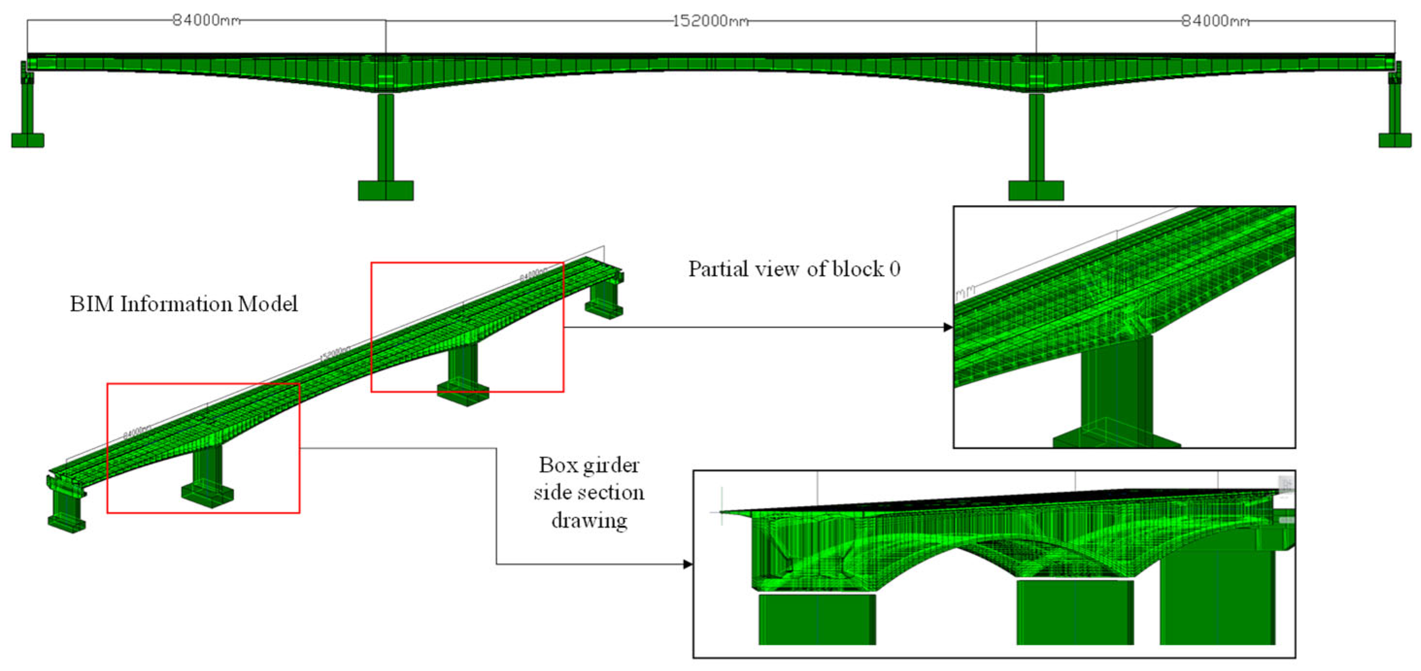
A DTS was deployed during the construction of a highway continuous beam bridge. The bridge features a main span arrangement of 84 m + 152 m + 84 m. The core objective are as follows: dynamically updating mechanical computation parameters based on real-time monitoring data from specific construction conditions, thereby enhancing simulation accuracy of mechanical models. This approach improves the DT model’s real-time responsiveness and state prediction accuracy across multiple operational scenarios.
During the symmetrical construction phase of the bridge cantilever, the core module of the DT platform detected a sudden abnormal fluctuation in the monitoring equipment data. Through an integrated mechanical calculation engine, the platform injects dynamically changing mechanical parameters into the calculation model in real time to perform analysis and finally visualizes the analysis results into the DT information model through a color gradient mapping algorithm.

4.1. Continuous Beam Bridge Digital Twin Modeling

The steps for building a digital twin for a continuous beam bridge commences with systematic collation, scrutiny, and consolidation of critical documentation—including design drawings, construction records, and inspection reports. Subsequently, validated structural information undergoes digitization to achieve complete transformation from physical assets to structured datasets. Conclusively, leveraging this processed data, a DT information model is constructed using Revit alongside a dynamic mechanical simulation model developed in Midas Civil, with both models undergoing synchronized integration into the unified DT platform.
The cross-sectional configuration is characterized by the following key parameters: The deck slab exhibits a width of 20.5 m, while the bottom slab measures 13 m in width. The structure incorporates cantilevered flange slabs with a projection of 3.75 m, featuring thicknesses of 20 cm at the extremity and 75 cm at the root section, respectively. The girder depth varies from 9 m at support sections (corresponding to 1 16.9 of the span length) to 4 m at mid-span sections (equivalent to 1 38 of the span length). The depth transition follows a parabolic profile, increasing from 4 m to 9 m within a 2.5 m zone extending from the mid-span towards the pier locations. This geometric variation is mathematically defined by the equation: Y = 4 + 5   ×   X 2 72.5 2   where Y represents the girder depth and X denotes the distance from the mid-span.
Based on the aforementioned design parameters, the DT information model and structural analysis model were established. Figure 5 illustrates the general layout plan of the continuous girder bridge.

4.2. Dynamic Data Interaction and Real-Time Mechanical Analysis Calculation

A DT model is constructed based on the physical construction progress of the bridge to achieve automated real-time synchronization and structural mechanical analysis. Construction monitoring data and simulation data interact dynamically through the twin system, where real-time data fusion ensures continuous maintenance of high geometric-structural fidelity in the mechanical model.
Upon occurrence of sudden loads during bridge construction, a 1 , 000 , 000 N load mutation is captured in real-time by superstructure monitoring devices and transmitted to the DT platform data center. The load magnitude and its coordinate position are synchronized into corresponding nodes of the mechanical analysis model, triggering structural computation commands. After receiving parameter update instructions, the Midas Civil-based mechanical model is automatically reconstructed and executed, with analytical results mapped in real-time onto the DT visualization interface. The implementation steps are as follows:
The API command code is initially developed in the Python environment, with the execution sequence structured as follows: (1) nodal load application (including load definition, load case creation, load value input, and case assignment), (2) analysis computation initiation, and (3) result data output. The JSON parameter body for nodal load addition must achieve spatial mapping between monitoring device coordinates and finite element nodes, with real-time monitoring values dynamically bound to load parameters. Complete instruction coding is required for core functional modules including load operations, unit system management, and structural analysis.
Three-dimensional (3D) model construction is carried out using the B/S (Browser/Server) architecture. Three-dimensional data files are placed on the configured Web server, so that the Web-side deployment of the 3D model is realized, and the design of model interaction and update is conducted in subsequent stages. Asynchronous communication with the back-end is implemented via the fetch API, where form data is sent and responses are received, thus achieving the dynamic processing of data.
For the back-end, based on the Python-based Flask framework and HTTP protocol, data transmission and function invocation are realized through well-defined Application Programming Interfaces (APIs). The GET method is used to obtain data files, while the POST method is adopted to submit parameters and execute logic. JSON is employed as the data exchange format, and Cross-Origin Resource Sharing (CORS) is used in conjunction to resolve cross-origin issues, thereby forming a clear and standardized front-end and back-end communication method.
Data interaction between the front-end and back-end is conducted by the front-end via HTTP requests. JSON is used as the data format, and the consistency of data formats between the front-end and back-end is ensured. The overall architecture of the platform involves multiple levels and modules. Through processes including perception, transmission, storage, analysis, decision-making, and presentation, real-time monitoring, refined management, and scientific decision support for the bridge construction process are achieved.
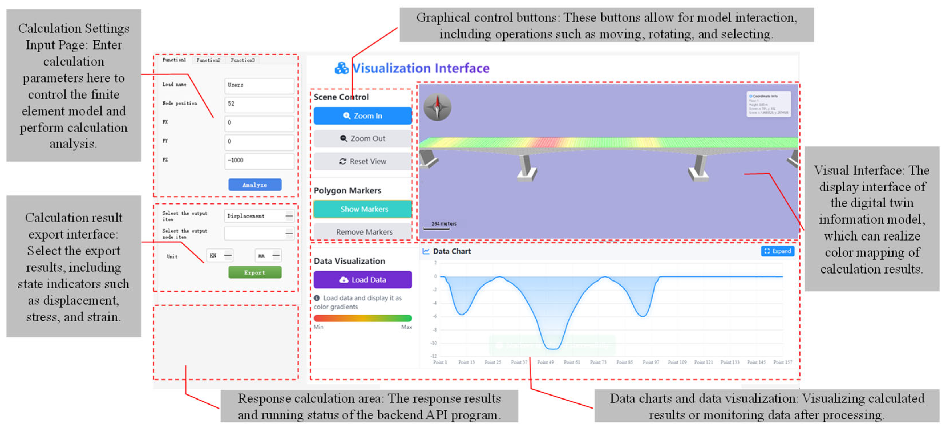
Following the integration of Midas Civil with the DT system, operations are executed through Figure 6 interface by first entering monitoring data ( 1 , 000 , 000 N in FZ direction, acting on node 52 ) with output units set to N/mm and displacement as the designated output in the left parameter panel. The “Analyze” and “Export” buttons are then sequentially clicked to transmit parameters to the backend mechanical model, after which the “Load Data” button is triggered upon result return to synchronously update the DT visualization model.
This platform achieves full-process integration management from physical bridge monitoring data to finite element mechanical analysis. Leveraging real-time sensor data streams and automated triggering mechanisms, it establishes a three-dimensional, bidirectional, high-fidelity mapping among the DT information model, mechanical analysis model, and physical structure. The system supplies construction managers with dynamic decision-making support, enabling precision control of construction processes and proactive safety risk prevention.
Relying on real-time sensor data streams and automatic trigger analysis mechanisms, a three-dimensional, bidirectional, high-precision mapping of digital twin information models, mechanical analysis models, and physical entities is constructed to provide dynamic decision-making support for construction management personnel, enabling precise control of the construction process and proactive safety risk prevention and control.

5. Conclusions and Future Work

A DTS integrated with mechanical analysis capabilities was developed based on the proposed system architecture. By establishing a three-layered structure—comprising the physical entity layer, the twin model layer, and the dynamic interaction layer—multi-source heterogeneous data, including continuous bridge component design information, physical monitoring data, visualization models, and FE analysis models, were effectively integrated and managed within a unified DT framework. To embed finite element simulation capabilities into the DT management platform, the Midas API was utilized for secondary development, enabling the seamless incorporation of FE analysis functions within the DTS. Through the fusion and processing of multi-source heterogeneous data, automated model updates and data-driven mechanical computations were achieved. As a result, the system enables integrated monitoring of the physical bridge structure and its mechanical performance analysis directly on the DT platform. The proposed DT system successfully combines DT technology with FE-based mechanical analysis, providing a powerful tool for structural behavior evaluation and predictive diagnostics throughout the service life of the infrastructure. Moreover, it offers more efficient and reliable decision-making support for project managers.
In future work, parameter identification and model updating techniques can be incorporated to achieve a more comprehensive, accurate, and real-time representation of physical entities within the DTS.

Author Contributions

Authorship contributions: L.C.: Writing—review & editing, Writing—original draft, Methodology. P.H.: Writing—review & editing. M.C.: Resources. Z.L.: Writing—review & editing. G.S.: Writing—review & editing, Supervision. D.H.: Writing—review & editing, Visualization. All authors have read and agreed to the published version of the manuscript.

Funding

The authors gratefully acknowledge the financial support provided by the Science and Technology Project of Jiangxi Provincial Department of Transportation (No. 2024ZG007).

Institutional Review Board Statement

Not applicable.

Informed Consent Statement

Written informed consent was obtained from all participants after explaining the study objectives, potential risks, and their right to withdraw at any stage.

Data Availability Statement

Data will be made available upon request.

Acknowledgments

The algorithms and implementation approach for the proposed digital twin system are elaborated in the paper. Readers can use Python to implement the algorithms and generate the results presented in the paper. The codes can be accessed upon reader’s requirement.

Conflicts of Interest

Authors Linhui Cao, Peng Hu, Maomao Chen and Zhanghong Liu were employed by the following companies: (1) Jiangxi Ganyue Expressway Co., Ltd., and (2) Jiangxi Communications Investment Group Co., Ltd. The remaining authors declare that the research was conducted in the absence of any commercial or financial relationships that could be construed as a potential conflict of interest.

References

  1. Zhao, Y.; Taib, N. Cloud-based Building Information Modelling (Cloud-BIM): Systematic literature review and Bibliometric-qualitative Analysis. Autom. Constr. 2022, 142, 104468. [Google Scholar] [CrossRef]
  2. Grieves, M. Origins of the Digital Twin Concept; Florida Institute of Technology/NASA: Melbourne, FL, USA, 2016. [Google Scholar]
  3. VanDerHorn, E.; Mahadevan, S. Digital Twin: Generalization, characterization and implementation. Decis. Support Syst. 2021, 145, 113524. [Google Scholar] [CrossRef]
  4. Jiang, F.; Ma, L.; Broyd, T.; Chen, K. Digital twin and its implementations in the civil engineering sector. Autom. Constr. 2021, 130, 103838. [Google Scholar] [CrossRef]
  5. Li, L.; Aslam, S.; Wileman, A.; Perinpanayagam, S. Digital Twin in Aerospace Industry: A Gentle Introduction. IEEE Access 2022, 10, 9543–9562. [Google Scholar] [CrossRef]
  6. Sun, T.; He, X.; Li, Z. Digital twin in healthcare: Recent updates and challenges. Digit. Health 2023, 9, 20552076221149651. [Google Scholar] [CrossRef] [PubMed]
  7. Pesantez, J.E.; Alghamdi, F.; Sabu, S.; Mahinthakumar, G.; Berglund, E.Z. Using a digital twin to explore water infrastructure impacts during the COVID-19 pandemic. Sustain. Cities Soc. 2022, 77, 103520. [Google Scholar] [CrossRef] [PubMed]
  8. Kritzinger, W.; Karner, M.; Traar, G.; Henjes, J.; Sihn, W. Digital Twin in manufacturing: A categorical literature review and classification. IFAC-PapersOnLine 2018, 51, 1016–1022. [Google Scholar] [CrossRef]
  9. Madubuike, O.C.; Anumba, C.J.; Khallaf, R. A review of digital twin applications in construction. J. Inf. Technol. Constr. 2022, 27, 145–172. [Google Scholar] [CrossRef]
  10. Hadjidemetriou, L.; Stylianidis, N.; Englezos, D.; Papadopoulos, P.; Eliades, D.; Timotheou, S.; Polycarpou, M.M.; Panayiotou, C. A digital twin architecture for real-time and offline high granularity analysis in smart buildings. Sustain. Cities Soc. 2023, 98, 104795. [Google Scholar] [CrossRef]
  11. Weil, C.; Bibri, S.E.; Longchamp, R.; Golay, F.; Alahi, A. Urban Digital Twin Challenges: A Systematic Review and Perspectives for Sustainable Smart Cities. Sustain. Cities Soc. 2023, 99, 104862. [Google Scholar] [CrossRef]
  12. Yang, H.; Jiang, G.; Tian, W.; Mei, X.; Nee, A.Y.C.; Ong, S.K. Microservice-based digital twin system towards smart manufacturing. Robot. Comput.-Integr. Manuf. 2025, 91, 102858. [Google Scholar] [CrossRef]
  13. Zhang, H.; Zhou, Y.; Zhu, H.; Sumarac, D.; Cao, M. Digital Twin-Driven Intelligent Construction: Features and Trends. Struct. Durab. Health Monit. 2021, 15, 183–206. [Google Scholar] [CrossRef]
  14. Sepasgozar, S.M.E.; Hui, F.K.P.; Shirowzhan, S.; Foroozanfar, M.; Yang, L.; Aye, L. Lean Practices Using Building Information Modeling (BIM) and Digital Twinning for Sustainable Construction. Sustainability 2020, 13, 161. [Google Scholar] [CrossRef]
  15. Liu, Z.; Li, A.; Sun, Z.; Shi, G.; Meng, X. Digital Twin-Based Risk Control during Prefabricated Building Hoisting Operations. Sensors 2022, 22, 2522. [Google Scholar] [CrossRef] [PubMed]
  16. Reja, V.K.; Varghese, K.; Ha, Q.P. Computer vision-based construction progress monitoring. Autom. Constr. 2022, 138, 104245. [Google Scholar] [CrossRef]
  17. Zhao, Y.; Cao, C.; Liu, Z. A Framework for Prefabricated Component Hoisting Management Systems Based on Digital Twin Technology. Buildings 2022, 12, 276. [Google Scholar] [CrossRef]
  18. Wang, W.-C.; Weng, S.-W.; Wang, S.-H.; Chen, C.-Y. Integrating building information models with construction process simulations for project scheduling support. Autom. Constr. 2014, 37, 68–80. [Google Scholar] [CrossRef]
  19. González-Böhme, L.F.; Valenzuela-Astudillo, E. Mixed Reality for Safe and Reliable Human-Robot Collaboration in Timber Frame Construction. Buildings 2023, 13, 1965. [Google Scholar] [CrossRef]
  20. Wang, X.; Liu, C.; Song, X.; Cui, X. Development of an Internet-of-Things-Based Technology System for Construction Safety Hazard Prevention. J. Manag. Eng. 2022, 38, 04022009. [Google Scholar] [CrossRef]
  21. Kamari, M.; Ham, Y. AI-based risk assessment for construction site disaster preparedness through deep learning-based digital twinning. Autom. Constr. 2022, 134, 104091. [Google Scholar] [CrossRef]
  22. Liu, J.; Duan, L.; Lin, S.; Miao, J.; Zhao, J. Concept, Creation, Services and Future Directions of Digital Twins in the Construction Industry: A Systematic Literature Review. Arch. Comput. Methods Eng. 2024, 32, 319–342. [Google Scholar] [CrossRef]
  23. Lee, Y.; Kim, S.; Yoon, K. Class Abstraction and Upcasting for Self-evolving Digital Twin System. In Proceedings of the 2023 International Conference on Electronics, Information, and Communication (ICEIC), Singapore, 5–8 February 2023; pp. 1–3. [Google Scholar]
  24. Zhang, J.; Chen, C.; Zhang, Y.; Cui, Y.; Han, P.; Meng, N.; Xu, Y. The Framework and Practices of Digital Twin City. In Proceedings of the 2022 IEEE 12th International Conference on Electronics Information and Emergency Communication (ICEIEC), Beijing, China, 15–17 July 2022; pp. 111–116. [Google Scholar]
  25. Obi, T.; Iwasaki, N. Smart Government using Digital Twin in Japan. In Proceedings of the 2021 International Conference on ICT for Smart Society (ICISS), Bandung, Indonesia, 2–4 August 2021; pp. 1–4. [Google Scholar]
  26. Hetherington, J.; West, M.; Makri, C.; Hajj, P.B.E. The Pathway Towards an Information Management Framework; Centre for Digital Built Britain: Cambridge, UK, 2020. [Google Scholar]
  27. Lu, Q.; Parlikad, A.K.; Woodall, P.; Don Ranasinghe, G.; Xie, X.; Liang, Z.; Konstantinou, E.; Heaton, J.; Schooling, J. Developing a Digital Twin at Building and City Levels: Case Study of West Cambridge Campus. J. Manag. Eng. 2020, 36, 05020004. [Google Scholar] [CrossRef]
  28. Zhang, R.; Wang, F.; Cai, J.; Wang, Y.; Guo, H.; Zheng, J. Digital twin and its applications: A survey. Int. J. Adv. Manuf. Technol. 2022, 123, 4123–4136. [Google Scholar] [CrossRef]
  29. Li, L.; Chen, T.; Kong, Q. The Study on Problems and Solutions of Digital Twin Technology Application under River Chief System. In Proceedings of the 2022 8th International Conference on Hydraulic and Civil Engineering: Deep Space Intelligent Development and Utilization Forum (ICHCE), Xi’an, China, 25–27 November 2022; pp. 647–650. [Google Scholar]
  30. Wang, B.; Zhang, C.; Zhang, M.; Liu, C.; Xie, Z.; Zhang, H. Digital Twin Analysis for Driving Risks Based on Virtual Physical Simulation Technology. IEEE J. Radio Freq. Identif. 2022, 6, 938–942. [Google Scholar] [CrossRef]
  31. Newrzella, S.R.; Franklin, D.W.; Haider, S. Methodology for Digital Twin Use Cases: Definition, Prioritization, and Implementation. IEEE Access 2022, 10, 75444–75457. [Google Scholar] [CrossRef]
  32. Botín-Sanabria, D.M.; Mihaita, A.-S.; Peimbert-García, R.E.; Ramírez-Moreno, M.A.; Ramírez-Mendoza, R.A.; Lozoya-Santos, J.d.J. Digital Twin Technology Challenges and Applications: A Comprehensive Review. Remote Sens. 2022, 14, 1335. [Google Scholar] [CrossRef]
  33. Orukele, O.; Polette, A.; Gonzalez Lorenzo, A.; Mari, J.L.; Pernot, J.P. A Data Structure for Developing Data-Driven Digital Twins. In Proceedings of the IFIP International Conference on Product Lifecycle Management, Bangkok, Thailand, 7–10 July 2024. [Google Scholar]
  34. Liu, S.; Lu, Y.; Zheng, P.; Shen, H.; Bao, J. Adaptive reconstruction of digital twins for machining systems: A transfer learning approach. Robot. Comput.-Integr. Manuf. 2022, 78, 102390. [Google Scholar] [CrossRef]
  35. Gattulli, V.; Franchi, F.; Graziosi, F.; Marotta, A.; Rinaldi, C.; Potenza, F.; Sabatino, U.D. Design and evaluation of 5G-based architecture supporting data-driven digital twins updating and matching in seismic monitoring. Bull. Earthq. Eng. 2022, 20, 4345–4365. [Google Scholar] [CrossRef]
  36. Van Den Brand, M.; Cleophas, L.; Gunasekaran, R.; Haverkort, B.; Negrin, D.A.M.; Muctadir, H.M. Models Meet Data: Challenges to Create Virtual Entities for Digital Twins. In Proceedings of the 2021 ACM/IEEE International Conference on Model Driven Engineering Languages and Systems Companion (MODELS-C), Fukuoka, Japan, 10–15 October 2021; pp. 225–228. [Google Scholar]
  37. Tao, F.; Cheng, J.; Qi, Q.; Zhang, M.; Zhang, H.; Sui, F. Digital twin-driven product design, manufacturing and service with big data. Int. J. Adv. Manuf. Technol. 2017, 94, 3563–3576. [Google Scholar] [CrossRef]
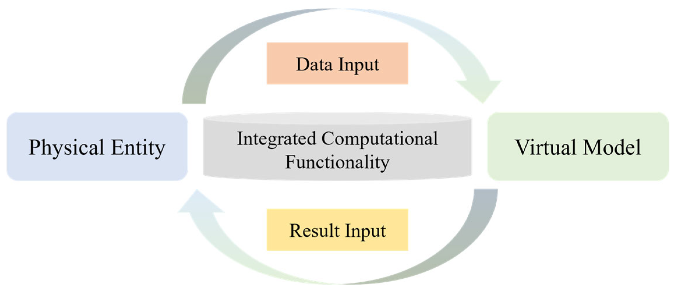
Figure 1. Digital Twin System Functional Diagram. This diagram illustrates the core workflow of the proposed DTS, designed to enable real-time mechanical analysis via multi-source heterogeneous data fusion. The physical entity feeds monitoring data into the integrated computational module; after processing, results are fed back to the virtual model to achieve dynamic synchronization between physical and virtual spaces.
Buildings 15 04228 g001
Figure 2. Architecture Diagram of a Digital Twin System Incorporating Mechanical Calculation Functionality. The system adopts a three-layer structure: the physical entity layer acquires environmental and operational data through sensors (e.g., strain gauges, total stations); the twin model layer integrates a BIM-based DT information model and a finite element analysis (FEA) mechanical model; the dynamic interaction layer (core) realizes cross-layer data transmission and integrates Midas Civil’s mechanical calculation functions via API. This architecture facilitates real-time physical-virtual data synchronization and automated mechanical analysis.
Buildings 15 04228 g002
Figure 3. API Program Data Fusion Principle Diagram. This diagram illustrates the fusion of multi-source monitoring data (e.g., displacement, load, stress, material properties) into the FEA model via API commands. The JSON parameter file serves as the carrier for computational parameters—for instance, vertical load monitoring data is assigned to the “FZ” field (defined as add_vertical_load) to accurately map real-world data to FEA nodes. GET/POST/PUT/DELETE commands enable dynamic creation, modification, query, and deletion of the FEA model.
Buildings 15 04228 g003
Figure 4. Basic roadmap for data fusion and transmission in digital twin systems. This diagram depicts the complete data flow in the DTS, spanning from monitoring data collection to result visualization. Bridge monitoring data (e.g., displacement, stress) is first denoised, repaired, and extracted; selected data are transmitted as computational parameters to the API program via HTTP; after mechanical calculation, results are stored, analyzed, and visually mapped on the DT platform to support engineering decision-making and structural condition prediction.
Buildings 15 04228 g004
Figure 5. Overall structure and detailed structural diagram of continuous beam bridge. The bridge adopts a main span configuration of 84 m + 152 m + 84 m, with magnified windows highlighting key cross-sections critical for mechanical modeling. These sections feature variable girder depths (4 m at mid-span, 9 m at supports) and cantilever flange slab dimensions (3.75 m projection, 20–75 cm thickness), supplying critical geometric parameters for establishing the FEA model and ensuring computational accuracy.
Buildings 15 04228 g005
Figure 6. Example Interface and Operation Diagram. The left parameter panel enables users to input monitoring data (e.g., −1,000,000 N in the FZ direction acting on node 52) and set output units (N/mm) and indicators (displacement). The color contour on the visualization interface represents structural displacement distribution (color scale: blue = minimum displacement, red = maximum displacement). Clicking “Analyze” triggers backend API-driven mechanical calculation, and “Load Data” synchronizes results to the 3D model, facilitating intuitive visualization of structural responses to abnormal loads.
Buildings 15 04228 g006
Disclaimer/Publisher’s Note: The statements, opinions and data contained in all publications are solely those of the individual author(s) and contributor(s) and not of MDPI and/or the editor(s). MDPI and/or the editor(s) disclaim responsibility for any injury to people or property resulting from any ideas, methods, instructions or products referred to in the content.