


Abstract
As a critical element within the prefabricated structural system, the prefabricated shear wall connected by sleeve grouting is renowned for its superior mechanical performance and high construction efficiency. It is widely applied in mid- and high-rise buildings. However, under fire conditions, not only do the material properties degrade, but the structural connections may also fail, significantly compromising the structural stability and safety. Therefore, this study delves into the fire resistance performance of such prefabricated shear walls. The research primarily focuses on analyzing fire resistance characteristics, including deformation patterns, lateral and axial deformations, fire resistance limits, and other performance metrics, for both prefabricated and cast-in-place shear walls subjected to three hours of single-sided fire exposure. Additionally, a parametric analysis is performed. The results reveal that, after three hours of single-sided fire exposure, the temperature distribution patterns at the mid-width and mid-height sections of the prefabricated shear wall generally resemble those of the cast-in-place wall, displaying arch-shaped and strip-shaped distributions, respectively. However, due to the presence of sleeves, higher temperatures are observed near the sleeve areas in the prefabricated wall, along with a more extensive high-temperature zone. Throughout the three-hour fire exposure, both types of shear walls demonstrated satisfactory structural stability and thermal insulation performance, meeting the requirements for a first-level fire resistance rating (3 h). Nevertheless, greater axial and lateral deformations were noted in the prefabricated shear wall. Key factors influencing the fire resistance performance of the sleeve-connected prefabricated shear wall include the axial compression ratio, longitudinal reinforcement diameter, protective layer thickness, and height-to-thickness ratio. Specifically, axial deformation is found to be directly proportional to the axial compression ratio and height-to-thickness ratio, while inversely proportional to the longitudinal reinforcement diameter and protective layer thickness. Lateral deformation is directly proportional to the axial compression ratio and longitudinal reinforcement diameter, and exhibits a trend of initially increasing and then decreasing with an increase in protective layer thickness, and initially decreasing and then increasing with an increase in the height-to-thickness ratio.
1. Introduction
Prefabricated construction as a key component of substantial buildings has received significant support from the government and is widely applied in all parts of the world, and due to its advantages as an important aspect of construction and building practices, it brings several advantages, such as increased efficiency in building construction, lower cost of energy and minimal environmental damage [1,2,3,4]. Along with the further speeding up of urbanization, the supply of urban land has also become limited, which leads to a significant increase in the number of high-rise and super high-rise buildings, which now form an important part of contemporary urbanization. Prefabricated shear walls, being the main structural component of prefabricated high-rise buildings, are necessary to provide the vertical rating of loads and withstand the lateral stress in a disaster like fire and earthquakes.
Fire is one of the most common disasters that building structures may face during their service life [5]. The extreme heat generated in a fire can degrade the properties of materials like concrete and steel, causing structural damage that may, in severe cases, escalate to overall instability and collapse. Prefabricated shear wall structures, inherently complex, have connection nodes as their critical vulnerabilities. Their fire resistance is determined not only by the inherent heat resistance of their constituent materials but also significantly shaped by factors like node connection design and construction quality. Existing studies have extensively investigated the performance evolution of concrete subjected to high temperatures at the material level. Nematzadeh et al. and Tayebi et al. experimentally examined the high-temperature behavior of steel fiber-reinforced concrete incorporating nylon particles and zeolite, demonstrating that these admixtures significantly influence the material’s impact resistance, flexural performance, and microstructural characteristics [6,7,8]. Furthermore, Li Zhi et al. analyzed the dynamic response and progressive collapse resistance of reinforced concrete (RC) frames under elevated temperatures from a structural perspective and proposed corresponding evaluation methodologies [9]. Additionally, Li Zhongyou et al. developed an analytical model to characterize the performance degradation of ordinary silicate cement concrete at high temperatures, thereby providing a theoretical foundation for subsequent structural fire resistance assessments at the material level [10]. Scholars such as Zhang W, Zhang Wangxi and Wang T have thoroughly examined the fire resistance of commonly used nodes and connectors in prefabricated shear walls. Their studies reveal that the mechanical properties of these nodes and connectors substantially deteriorate under high temperatures, diminishing the overall structural stability [11,12,13,14,15]. Consequently, the compromised performance of nodes and connectors under fire inevitably weakens the fire resistance of the entire prefabricated shear wall system. To date, both domestic and international scholars have carried out extensive research on the performance of shear walls under fire conditions. Ni et al. [16] utilized numerical simulation methods to analyze the impact of fire-induced damage on the lateral load-bearing capacity of flexure-dominated reinforced concrete (RC) structural walls. They found that fire exposure significantly reduced the load-bearing capacity and stiffness of RC walls under cyclic loading. Lee et al. [17] carried out fire tests on eight reinforced concrete walls under bilateral ISO-834 [18] standard fire conditions, concluding that walls with thinner profiles were more prone to fire-induced damage when subjected to axial loads. Xing Yonghui et al. [19] examined the stiffness degradation behavior of shear walls under fire exposure, revealing that stiffness decreased progressively with increasing fire exposure time. Higher axial compression ratios were found to expedite stiffness degradation, elevate the likelihood of local instability, and exacerbate stiffness loss as temperatures rose. Zheng Yonggan, Cai Xuefeng et al. [20] simulated the entire deformation process of reinforced concrete walls under fire conditions and found that fire resistance performance declined with increases in axial compression ratio, lateral load ratio, height-to-thickness ratio, reinforcement yield strength, and reinforcement ratio. Xiao Jianzhuang et al. [21] experimentally investigated the fire resistance performance of high-strength concrete shear walls, observing that cast-in-place high-strength concrete shear walls suffered severe cracking under standard fire exposure. Thanyawat et al. [22] explored the fire response of precast concrete load-bearing walls using three-dimensional thermal and structural models, with their results indicating that fire resistance performance worsened with rising load levels and slenderness ratios. However, the application of rotational constraints at the wall ends improved the fire resistance rating. From the aforementioned studies, it is evident that fire has a detrimental impact on the load-bearing capacity, deformation capacity, and overall fire resistance performance of shear walls. Nevertheless, most of the current studies have concentrated on the traditional cast-in-place shear walls. In the case of prefabricated shear walls with multiple material combinations, and incorporation of complex connection nodes, an enormous research gap, still exists, in terms of the overall structural behavior during a fire condition of high temperature, node connection behavior development, and development of specific fire resistance design programs. Hence, the comprehensive and thorough study on this matter is urgently required in order to offer a firm technical base on the development of fire safety in prefabricated construction.
In this study, precast shear walls with sleeve grouting connections—one of the most widely used connection types in practical engineering—are selected as the research object. A thermo-mechanical coupled finite element model for investigating their fire resistance performance is established and validated. Subsequently, a parametric analysis on the fire resistance of such precast shear walls is conducted, focusing on exploring the influences of key factors including axial compression ratio, longitudinal reinforcement diameter, and sleeve length. The research findings provide valuable guidance and references for the fire-resistant design, optimization, and performance evaluation of precast shear walls with sleeve grouting connections.
2. Finite Element Model
In this study, the ABAQUS 2020 (Dassault Systèmes, Providence, RI, USA) finite element software was utilized to perform a finite element analysis on the fire resistance performance of prefabricated shear walls connected through sleeve grouting. First, a temperature field analysis model was developed; subsequently, the results from the temperature field analysis were incorporated into the mechanical model to enable the analysis of thermo-mechanical coupling behavior.
2.1. Model Size
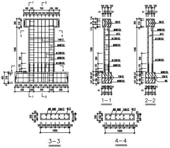
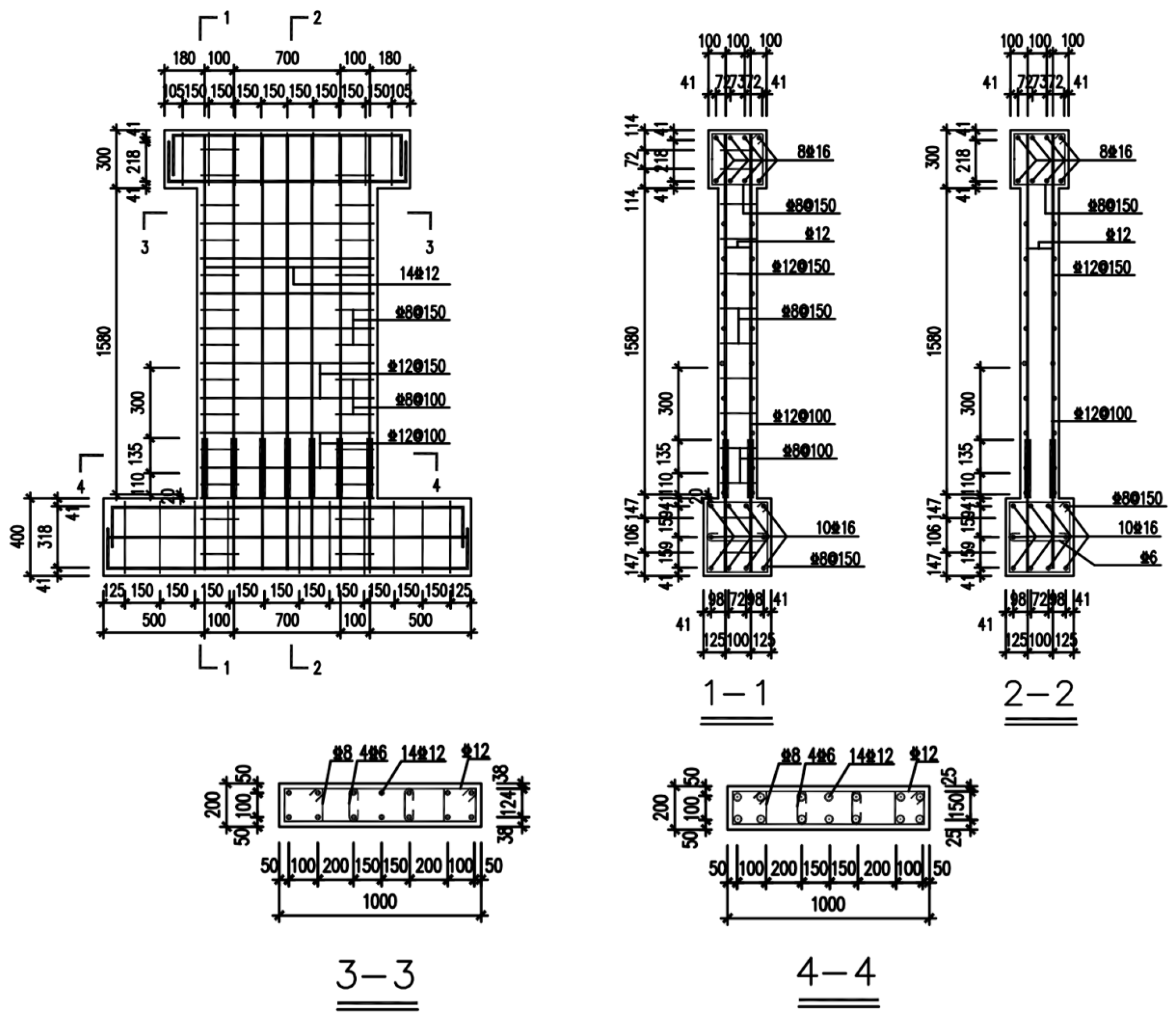
The prefabricated shear wall specimen JLQ3, connected through sleeve grouting as detailed in reference [23], was chosen as the research subject in this study. Its specific cross-sectional dimensions and reinforcement configuration are illustrated in Figure 1.
Figure 1.
The dimensions of the specimen and the reinforcement details (Unit:mm).
The prefabricated shear wall JLQ3, connected via sleeve grouting, consists of a wall panel, loading beams, and ground beams. The respective dimensions of these components are 1600 mm × 20 mm × 1000 mm for the wall panel, 300 mm × 300 mm × 1260 mm for the loading beams, and 350 mm × 400 mm × 1900 mm for the ground beams. All components are fabricated using C40-grade concrete. The reinforcement steel used throughout is of HRB400 grade. The wall panel is reinforced with longitudinal and transverse bars having a diameter of 12 mm, and 8 mm-diameter stirrups are also provided. The loading beams and ground beams share an identical reinforcement configuration, featuring full-length longitudinal bars with a diameter of 16 mm and 8 mm-diameter stirrups. The grouting sleeves used are of type GTQ4J12 (fully grouted), made from Q345 structural steel. Each sleeve has a length of 245 mm, an outer diameter of 38 mm, and a wall thickness of 3 mm. A concrete cover thickness of 25 mm is specified for the sleeves, the designed axial compression ratio is 0.2.
2.2. Development of the Finite Element Model
2.2.1. Development of the Temperature Field Model
- Unit Selection and Grid Discretization
In the modeling process, three-dimensional eight-node heat conduction solid elements (DC3D8) were employed to simulate the concrete, grouting material, and sleeve components, whereas two-node heat conduction truss elements (DC1D2) were employed for the reinforcing bars.
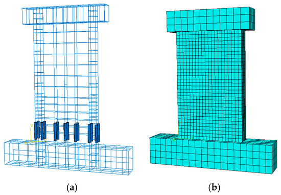
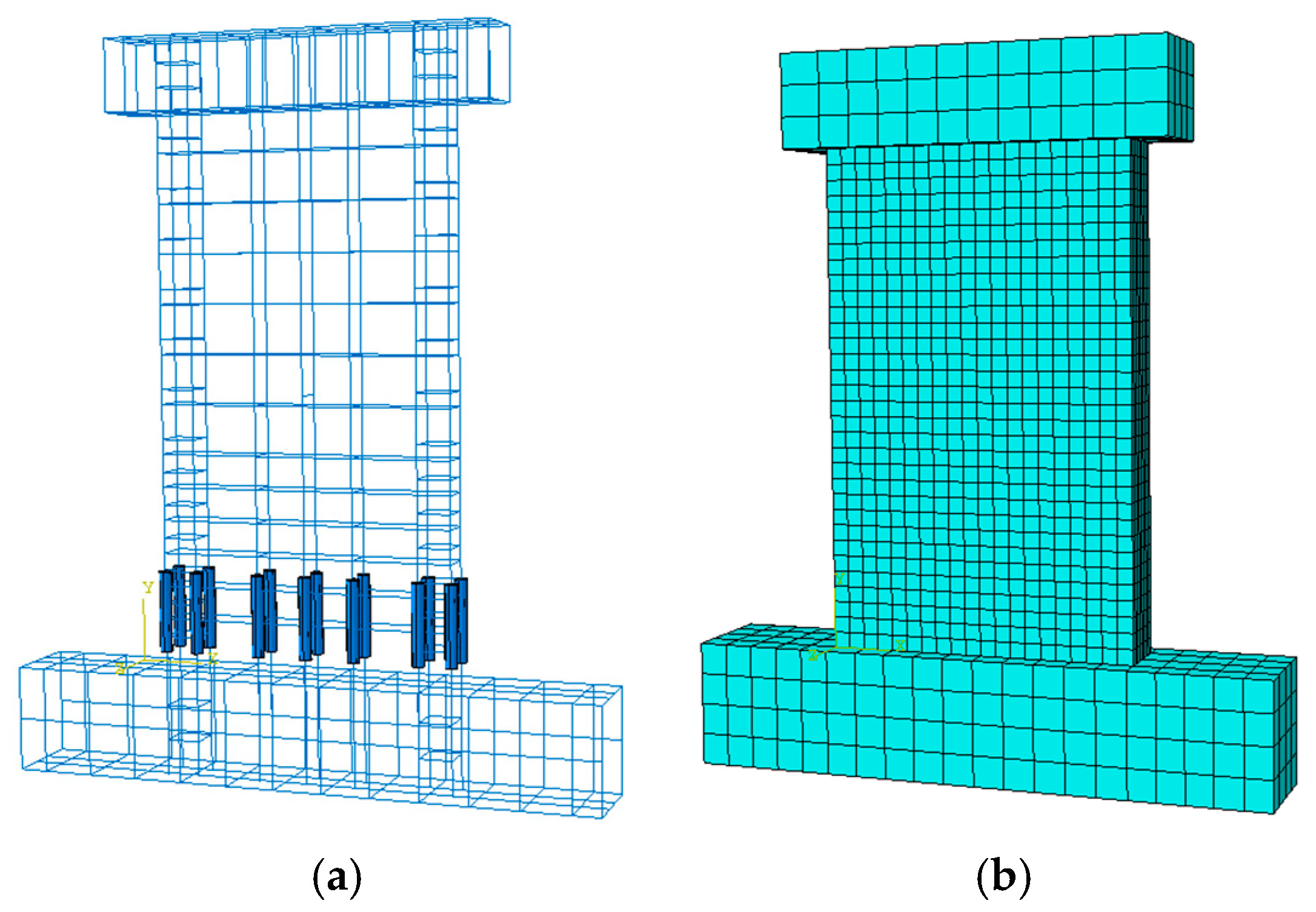
During mesh generation, element size exerts a significant influence on the accuracy of simulation results. Generally, smaller element sizes lead to higher accuracy but also result in an increased computational cost. After a comprehensive evaluation of computational efficiency and solution precision, the following discretization scheme was adopted: a grid size of 100 × 100 × 100 mm was applied to both the ground beam and loading beam; for the wall, the element size was set at 50 mm in both the height and width directions, and 25 mm in the thickness direction; the sleeve and grouting material were discretized using a 25 mm mesh size; and the reinforcing bars were modeled using a 50 mm element length. The computational model obtained is depicted in Figure 2.
Figure 2.
Temperature field model: (a) Sleeves and steel cages; (b) Model meshing.
- 2.
- Material Properties
Three primary materials, like steel, concrete, and grouting material, are incorporated into the model. Currently, research on the high-temperature behavior of grouting materials is relatively scarce. However, it has been assumed in several studies that their thermal performance at elevated temperatures is similar to that of conventional concrete [12,24]. Based on this assumption, the same material property calculation models employed for concrete are also applied to the grouting material.
The thermal parameters for concrete, grouting material, and steel are determined through the formulas stipulated in the European standard EC2 [25]. The densities of concrete and steel are set as constant values, specifically 2400 kg/m3 and 7850 kg/m3, respectively.
- 3.
- Interaction
During the modeling, the built-in area method is utilized for embedding the reinforcing bars outside the sleeve and the sleeve itself into the concrete matrix. To define the interactions among various components, such as between the loading beam and the wall, the ground beam and the wall, the grouting material and the sleeve, and the areas where the wall’s longitudinal reinforcement extends into the grouting material, binding constraints (Tie) are uniformly applied at all interfaces.
- 4.
- Boundary Conditions
The thermal boundary conditions of the model are set to conform to the experimental setup. Specifically, the ISO-834 standard fire curve is adopted, with a four-sided fire exposure configuration and a total exposure duration of 113 min. To ensure that the simulated thermal environment closely replicates the test conditions, the following parameters are assigned: On the exposed surfaces, a convective heat transfer coefficient of 10 W/(m2 · °C) and a surface emissivity of 0.1 are designated to represent the combined convective and radiative heat exchange. On the unexposed surfaces, a convective heat transfer coefficient of 6 W/(m2 · °C) is applied to simulate natural convection under ambient conditions.
2.2.2. Development of Mechanical Models
- Unit Selection and Grid Division
To guarantee the accuracy of the thermo-mechanical coupling analysis, geometric consistency must be maintained between the fire resistance performance analysis model and the temperature field analysis model in terms of dimensions, mesh discretization, and node numbering, with specific configurations identical to those detailed in the previous chapter. Regarding the selection of material unit types: C3D8R elements (eight-node linear brick elements with reduced integration) are utilized for concrete, sleeves, and grouting materials, while T3D2 elements (two-node linear three-dimensional truss elements) are adopted for steel reinforcement.
- 2.
- Material Constitutive Model Selection
In the mechanical model, a plastic constitutive model incorporating damage evolution, specifically, the Concrete Damaged Plasticity (CDP) model, is adopted for both concrete and grouting materials. The stress–strain relationship is based on the formulation proposed by Zhen Hai [26], and the values of other relevant plastic parameters are summarized in Table 1.
Table 1.
Plastic Parameters of the CDP Model.
In the formula, denotes the peak strain of concrete at high temperatures, and εp represents the peak strain of concrete in a normal temperature environment, which can be determined in accordance with the relevant provisions of the current “Code for Design of Concrete Structures” [27].
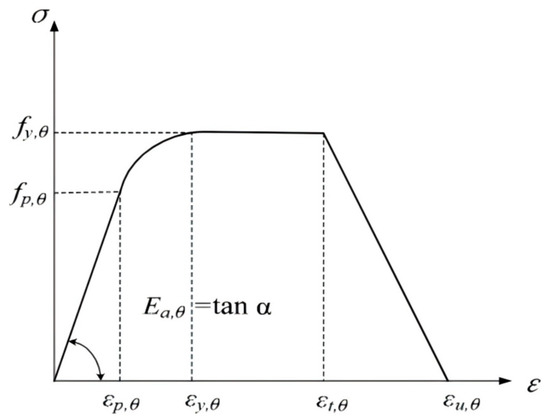
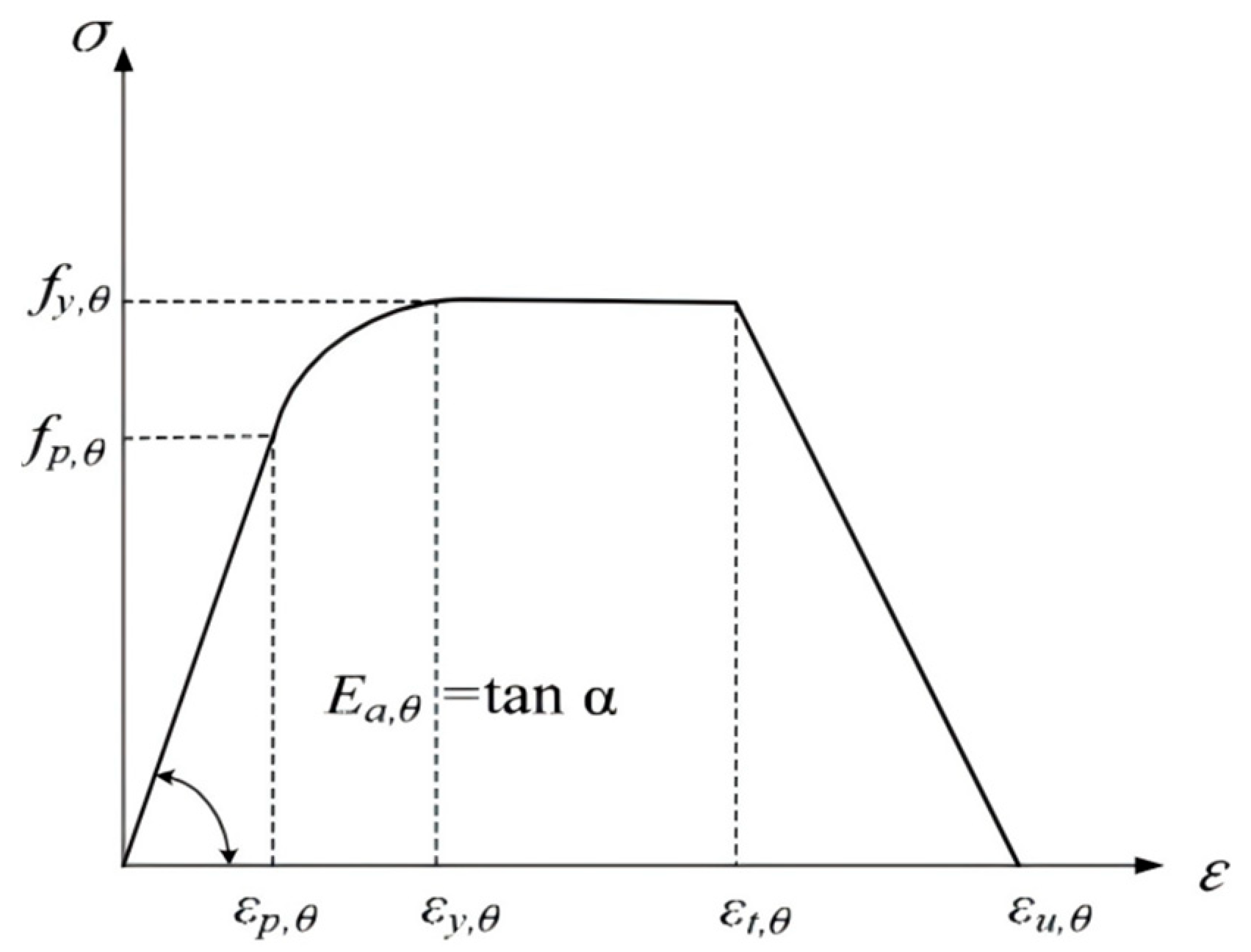
The reinforcing bars and sleeves use an elastoplastic constitutive model, with the stress–strain relationship derived from the formulation recommended by EC2 [25].
The strain parameters are defined as follows: εp(T) = fp(T)/Es(T), εy(T) = 0.02, εt(T) = 0.15, εu(T) = 0.2. In the process of calculating the constitutive model of steel at elevated temperatures, the parameters a, b, and c are determined utilizing the following equations.
In the formula, fy(T) denotes the yield strength; fp(T) represents the proportional limit; Es(T) refers to the initial elastic modulus; εp(T) indicates the strain in the steel corresponding to the proportional limit; εy(T) signifies the yield strain; εt(T) denotes the maximum strain at the yield strength; and εu(T) represents the ultimate strain, as illustrated in Figure 3.
Figure 3.
The Stress–strain Behavior of Reinforcing Steel at Elevated Temperatures.
Moreover, during structural mechanics analysis under fire conditions, thorough consideration must be given to the influence of materials’ thermal expansion coefficients. The thermal expansion coefficients for concrete and steel are determined in accordance with the formula recommended by EC2 [25].
- 3.
- Interaction
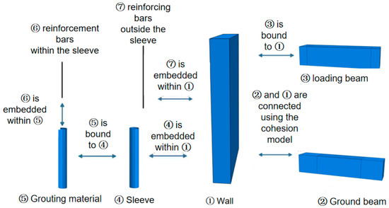
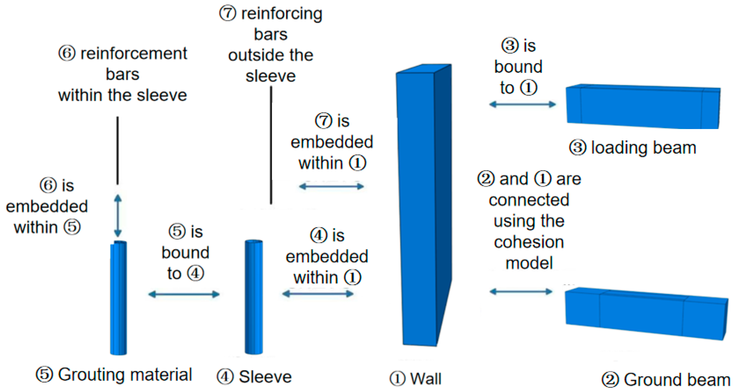
In the mechanical model, the interactions among components are depicted in Figure 4. The inner and outer reinforcing bars within the sleeve, as well as the interface between the sleeve and the grouting material, are modeled using embedded constraints to represent their integration into the surrounding concrete. The contact between the loading beam and the wall is defined by Tie constraints, ensuring coordinated deformation and enabling them to act as a unified load-bearing system. For the horizontal joints of prefabricated shear walls, non-shrinkage cement mortar is typically used for grouting in practical applications, displaying mechanical behavior akin to that of the interface between new and old concrete. Consequently, this study adopts the cohesive zone model and the Coulomb friction model based on established research [28,29] to simulate the interaction between the wall and the foundation beam. The cohesive zone model captures the interfacial bonding-slip behavior and damage evolution process, while the Coulomb friction model characterizes the frictional contact response between the contacting surfaces. For numerical implementation, a hard contact relationship is utilized in the normal direction, and a penalty-based method is applied in the tangential direction, with a friction coefficient set at 0.6.
Figure 4.
Schematic illustration of the interaction relationships among the mechanical models of prefabricated shear walls.
- 4.
- Analytical Procedures and Load Configuration
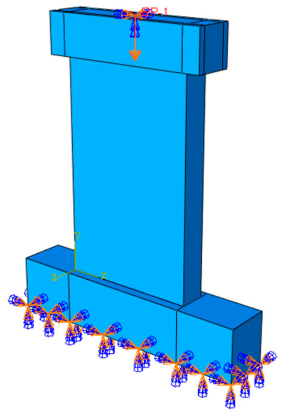
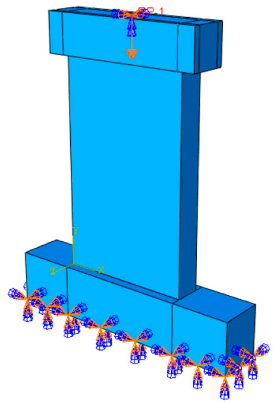
When conducting fire resistance performance analysis using the sequential thermal–structural coupling method, two distinct analysis steps are required. In the first step, a vertical load is applied to the top of the specimen, and appropriate boundary conditions are established, as illustrated in Figure 5. In the second step, the temperature field results obtained from the thermal analysis in the previous chapter are imported into the mechanical model to perform structural analysis under elevated temperatures. During the entire analysis, the mechanical load applied is kept constant, while the fire response is simulated by gradually raising the temperature until the structure attains its fire resistance limit state.
Figure 5.
Schematic illustration of the model loading and boundary conditions.
The vertical load is imposed through a reference point (RP-1), and this is connected to the upper surface of the loading beam to provide a proper simulation of the actual conditions of loading to the shear wall. It is then connected to RP-1 in order to distribute the load in terms of stress distribution. In line with reality fire circumstances, the shear wall is fixed at the bottom, which is a rigid foundation connection. At the top of the shear wall, translational and rotational constraints are applied in all directions except for the axial compression direction, where Ux = Uz = URx = URy = URz = 0, allowing axial deformation due to thermal expansion and structural response. The boundary conditions for the prefabricated shear wall connected by sleeve grouting are illustrated in Figure 5.
2.3. Experimental Validation of Validity
2.3.1. Verification of the Temperature Field Model
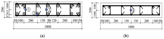
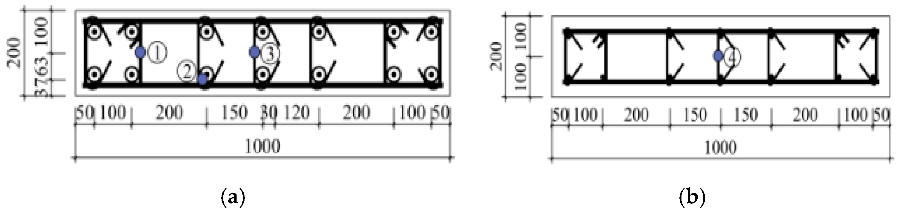
The above-mentioned modeling approach was utilized for simulating specimen JLQ3. Four temperature measurement points were installed within specimen JLQ3 to enable the acquisition of both the spatial distribution characteristics and the time-history variations of the internal temperature field in the shear wall, with their layout shown in Figure 6.
Figure 6.
Layout of temperature measurement points for Specimen JLQ3 (Unit:mm): (a) Cross-sectional view at a wall height of 120 mm; (b) Cross-sectional view at a wall height of 800 mm. Numbers①, ②, ③ and ④ represent the positions of four temperature measurement points, respectively.
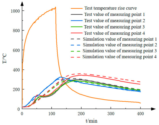
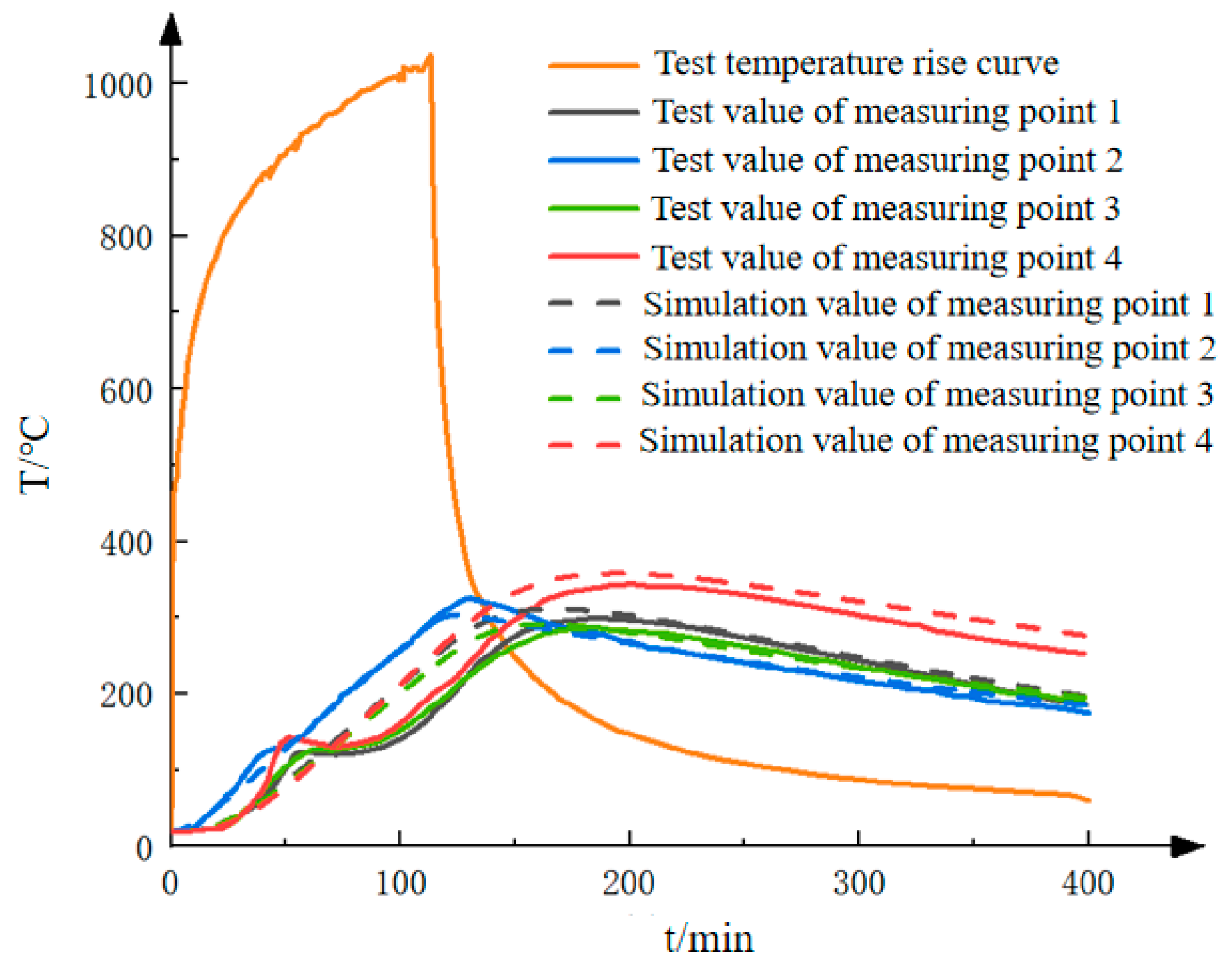
Figure 7 presents a comparison of the temperature-time curves at different measurement points for prefabricated shear wall specimen models with different thermal parameters, as obtained from finite element simulations and experimental tests. It can be observed from the figure that the simulated temperature-time curves generally follow the same trend as those from the experiments. Nevertheless, a time lag in reaching peak temperatures is observed in the simulation results compared to the test data. This discrepancy is primarily attributed to the presence of moisture within the concrete, which absorbs heat during evaporation, a factor not accounted for in the finite element model. As such, the influence of water vapor on the temperature field in sleeve-grouted prefabricated shear walls is not reflected in the current simulation setup.
Figure 7.
The temperature-time curves of each measurement point in the temperature field model.
Table 2 displays the maximum temperatures recorded at each measurement point, which are obtained from finite-element analysis. A comparison is also made between the time taken to reach these peak temperatures in the analysis and the experimental results. The data reveal that for the model using concrete thermal parameters specified by European standards, the predicted maximum temperatures at all measurement points show good alignment with the experimental measurements, with a maximum deviation of 6.34%. Moreover, the difference in the time to reach peak temperature is no more than 13%.
Table 2.
A comparative analysis of the maximum temperatures at each measurement point and the time taken to reach the maximum temperatures.
In conclusion, the temperature field simulation results presented in this study are found to be reasonably consistent with the experimental data reported in the literature. This suggests that the proposed temperature field model is reliable and can effectively simulate the thermal behavior of prefabricated shear walls connected by sleeve grouting when exposed to fire.
2.3.2. Verification of Mechanical Models
At present, experimental investigations into the fire resistance performance of prefabricated shear walls connected through sleeve grouting are still inadequate, and a scarcity of comprehensive data exists to verify the accuracy of existing fire resistance performance models. Given the substantial similarities in structural characteristics and load-bearing mechanisms between cast-in-place concrete shear walls and sleeve-grouted prefabricated shear walls, similar methodologies have been adopted in current studies to establish fire resistance analysis models for both. The validity of the thermomechanical coupling analysis modeling approach is evaluated by comparing simulation results with experimental data.
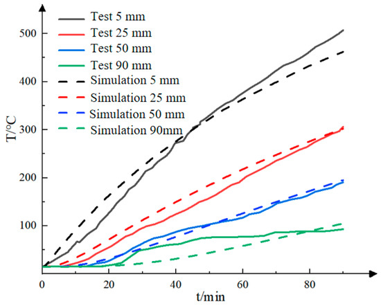
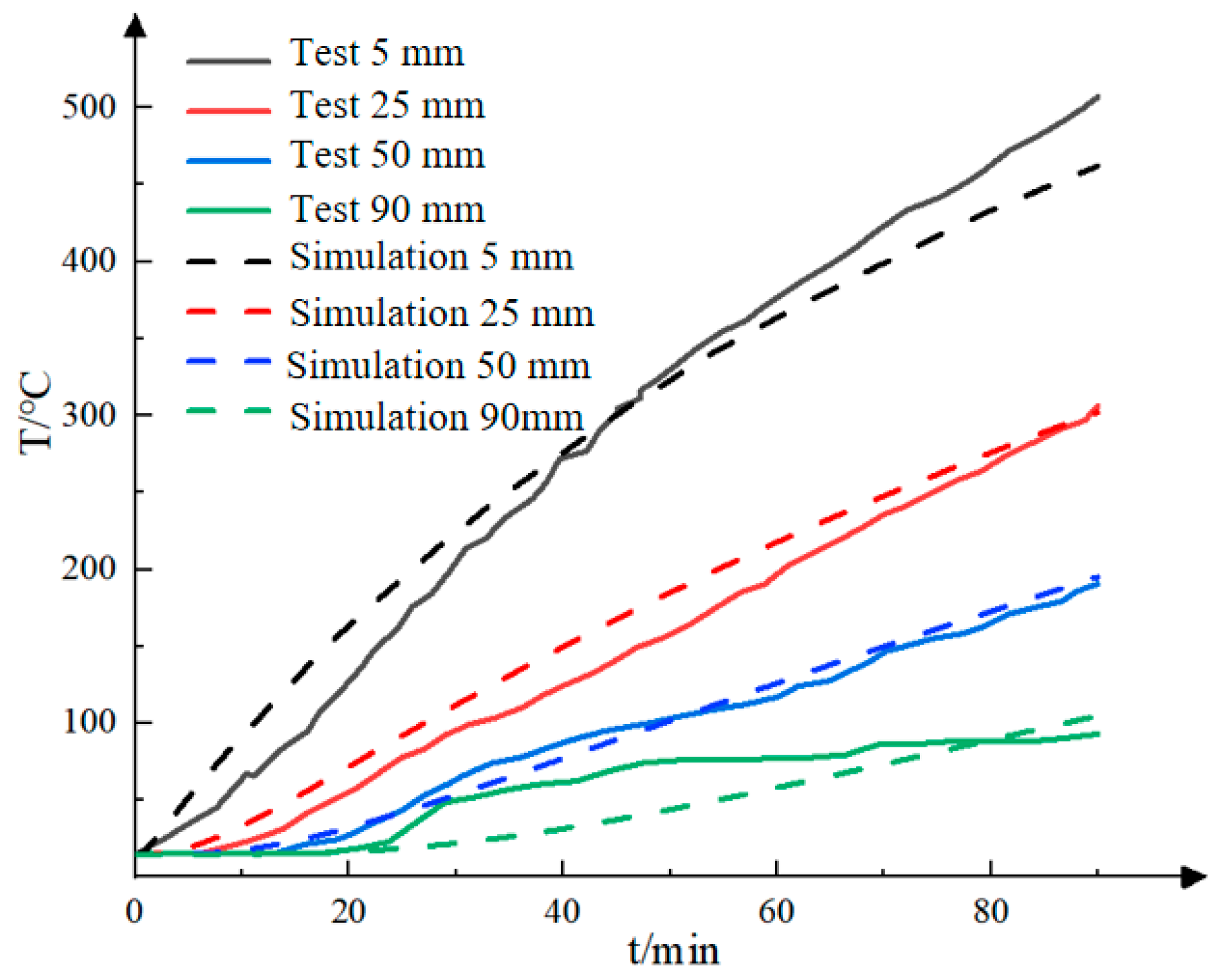
Figure 8 illustrates a comparison between the numerically simulated and experimentally measured temperature values at various monitoring points on the cast-in-place shear wall. It can be observed that the temperature–time curves generated from the simulation closely resemble the test data. The errors at all measurement points range from a minimum of 1.34% to a maximum of 12.27%, which is deemed an acceptable margin of deviation.
Figure 8.
Comparison of Temperature Values at Each Measurement Point in the Shear Wall with Test Results.
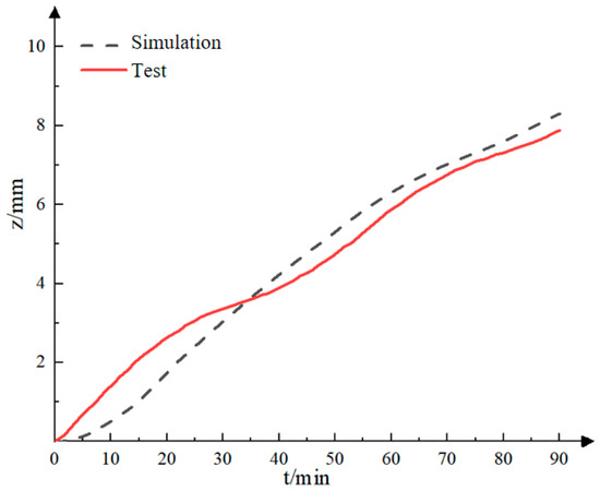
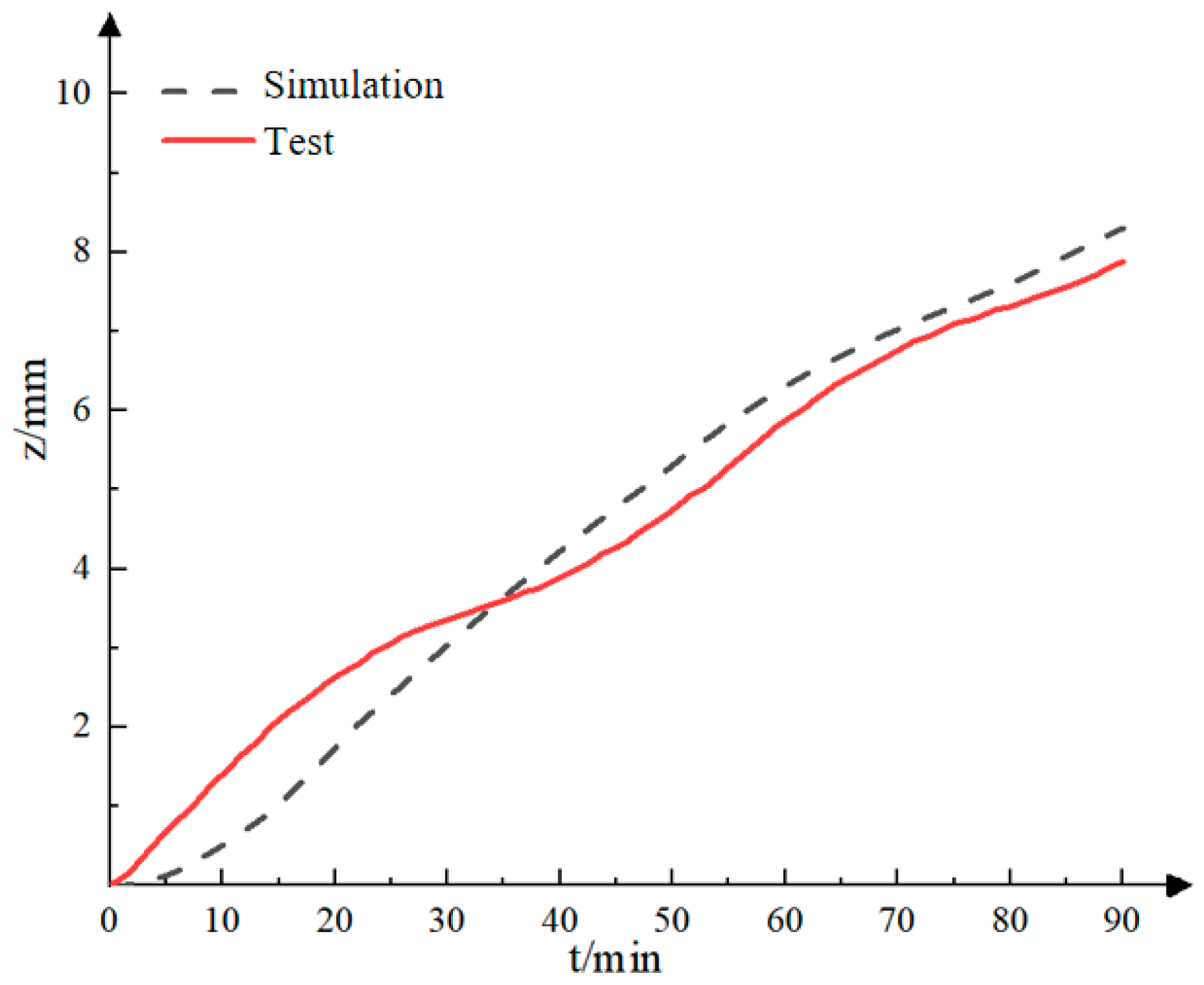
In Figure 9, a comparison of the out-of-plane mid-span displacement of the cast-in-place shear wall with experimental results is presented, revealing a trend of gradual increase over time. A comparison with published test data reveals that the time-history curve of out-of-plane displacement obtained from finite element analysis aligns well with the experimental outcomes. Specifically, the discrepancy between the simulated mid-span displacement and the test result is merely 0.03 mm, corresponding to an error of 0.04%, which is deemed negligible. Consequently, it can be concluded that the proposed thermomechanical coupling modeling method is both effective and rational.
Figure 9.
Presents a comparison of the out-of-plane displacement at the mid-span of the shear wall between the numerical simulation and the experimental test results.
Table 3 presents a comparison between the cross-sectional temperatures and mid-span out-of-plane displacements of cast-in-place shear walls. The data indicate that the cross-sectional temperature decreases with increasing distance from the fire-exposed surface, and the variation trend of the simulated values is consistent with that of the experimental results. Among all measured positions, the minimum error of 1.34% is observed at 25 mm from the fire-exposed surface, while the maximum error reaches 12.27% at 95 mm. Overall, the errors fall within the acceptable range for engineering analysis, reflecting the good accuracy of the model in simulating the temperature field. Furthermore, the error between the experimental value (7.88 mm) and the simulated value (7.91 mm) of the mid-span out-of-plane displacement is only 0.04% with an extremely small deviation, which further verifies the reliability of the model in predicting the wall deformation under fire conditions.
Table 3.
Comparison of section temperature and out-of-plane displacement at mid-span of cast-in-place shear walls.
3. Finite Element Analysis
3.1. Analysis of the Temperature Field
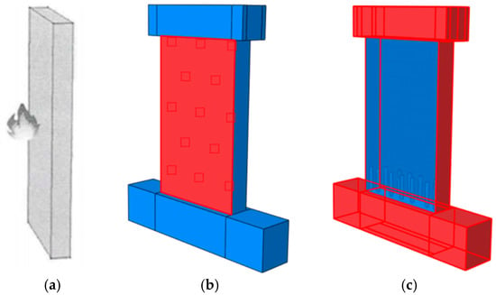
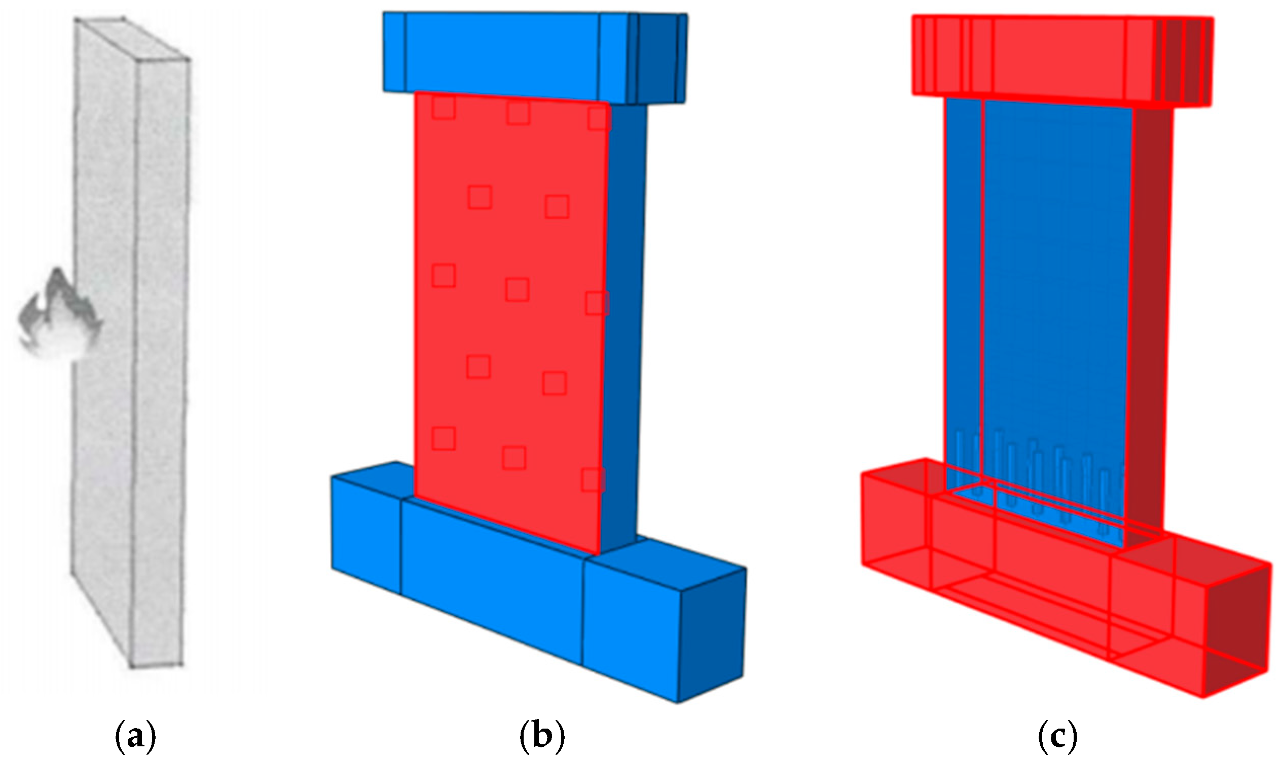
Following validation of the temperature field model, this study analyzes the thermal behavior of prefabricated shear walls connected through sleeve grouting, aiming to identify variations in temperature distribution compared to conventional cast-in-place shear walls. Given that building fires typically subject walls to one-sided fire exposure and in accordance with the Chinese “Code for Fire Protection Design of Buildings” [30], which stipulates a 3 h fire resistance rating for load-bearing walls, the analysis focuses on the temperature field of sleeve-grouted prefabricated shear walls under single-sided fire exposure for a duration of 3 h. The specific fire exposure configuration is depicted in Figure 10.
Figure 10.
Schematic illustration of the fire exposure configuration: (a) The side subjected to fire exposure; (b) The fire-exposed surface of the model; (c) The rear surface of the model exposed to fire.
To accurately simulate the actual fire behavior, drawing upon established research [31,32,33], the heat transfer boundary conditions of the model are defined as follows: the initial ambient temperature is set at 20 °C; the convective heat transfer coefficient and overall thermal radiation coefficient on the exposed surface are assigned values of 25 W/(m2·°C) and 0.5, respectively, while the convective heat transfer coefficient on unexposed surfaces is set to 9 W/(m2·°C).
- Cloud map illustrating the temperature field distribution
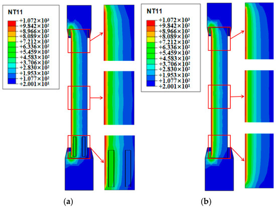
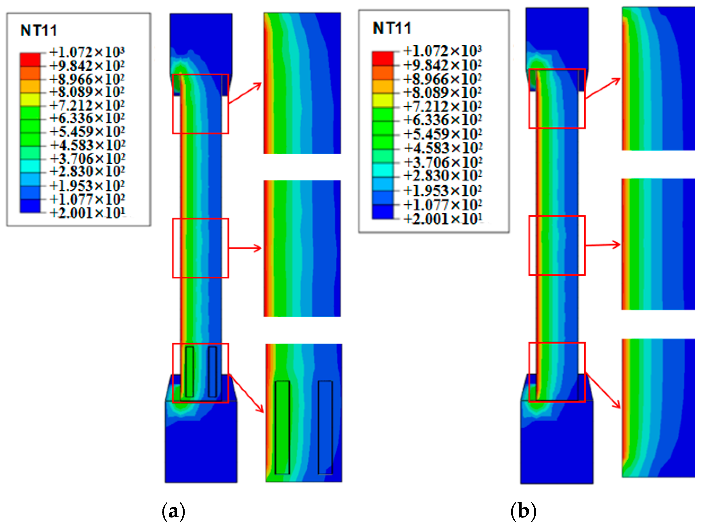
Figure 11 displays the temperature distribution cloud diagram for both the sleeve-grouted prefabricated shear wall and the cast-in-place shear wall at Section 2.2, after one-sided fire exposure for 3 h. As illustrated in Figure 11, both the cast-in-place and the prefabricated shear walls connected via sleeve grouting exhibit an approximately arched temperature field distribution at Section 2.2, with temperature gradually decreasing from the fire-exposed side to the unexposed side.
Figure 11.
The temperature distribution cloud map at Section 2.2 of the specimen: (a) prefabricated shear walls subjected to a 3 h fire exposure; (b) cast-in-place shear walls subjected to a 3 h fire exposure.
However, compared to the cast-in-place shear wall, the presence of sleeves in the prefabricated wall results in higher cross-sectional temperatures and an expanded high-temperature zone near the sleeves. This phenomenon can be attributed to the significantly higher thermal conductivity of the sleeve material relative to concrete. During heat transfer, the sleeves facilitate faster heat conduction, leading to greater heat accumulation and wider diffusion in surrounding areas. Consequently, the areas adjacent to the sleeves display elevated temperature levels and a broader distribution of high-temperature zones.
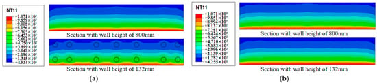
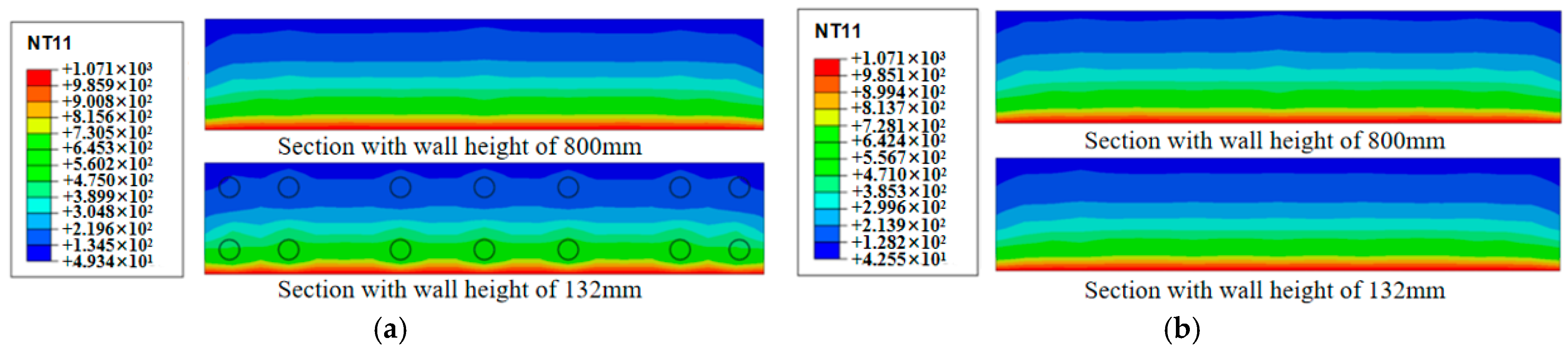
Figure 12 depicts the temperature distribution cloud map at the cross-sections located at 132 mm and 800 mm along the wall height, following a 3 h exposure to fire on one side. As shown in the figure, in the region without sleeves (at the 800 mm cross-section), the temperature field of the prefabricated shear wall connected via grouted sleeve joints exhibits a predominantly strip-like distribution. Minor fluctuations are observed around the embedded reinforcement layout within the wall, which aligns with the typical temperature field distribution pattern of cast-in-place shear walls. In contrast, in the sleeve region (at the 132 mm cross-section), the temperature distribution displays a combined strip and wave-like pattern. This deviation is primarily attributed to the presence of the sleeves, which modify the heat transfer path and rate. Owing to their relatively high thermal conductivity compared to concrete, sleeves enable heat to be conducted more efficiently, resulting in accelerated heat accumulation and diffusion being observed in both the sleeve material and its adjacent areas. Consequently, this results in a distinct temperature distribution profile compared to the sleeve-free region.
Figure 12.
The temperature distribution cloud map of the specimen at the cross-section along the wall height: (a) Cast-in-place shear walls that have been exposed to fire for 3 h; (b) Prefabricated shear walls that have been exposed to fire for 3 h.
- 2.
- Temperature-Time Profile
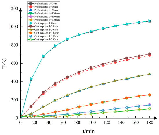
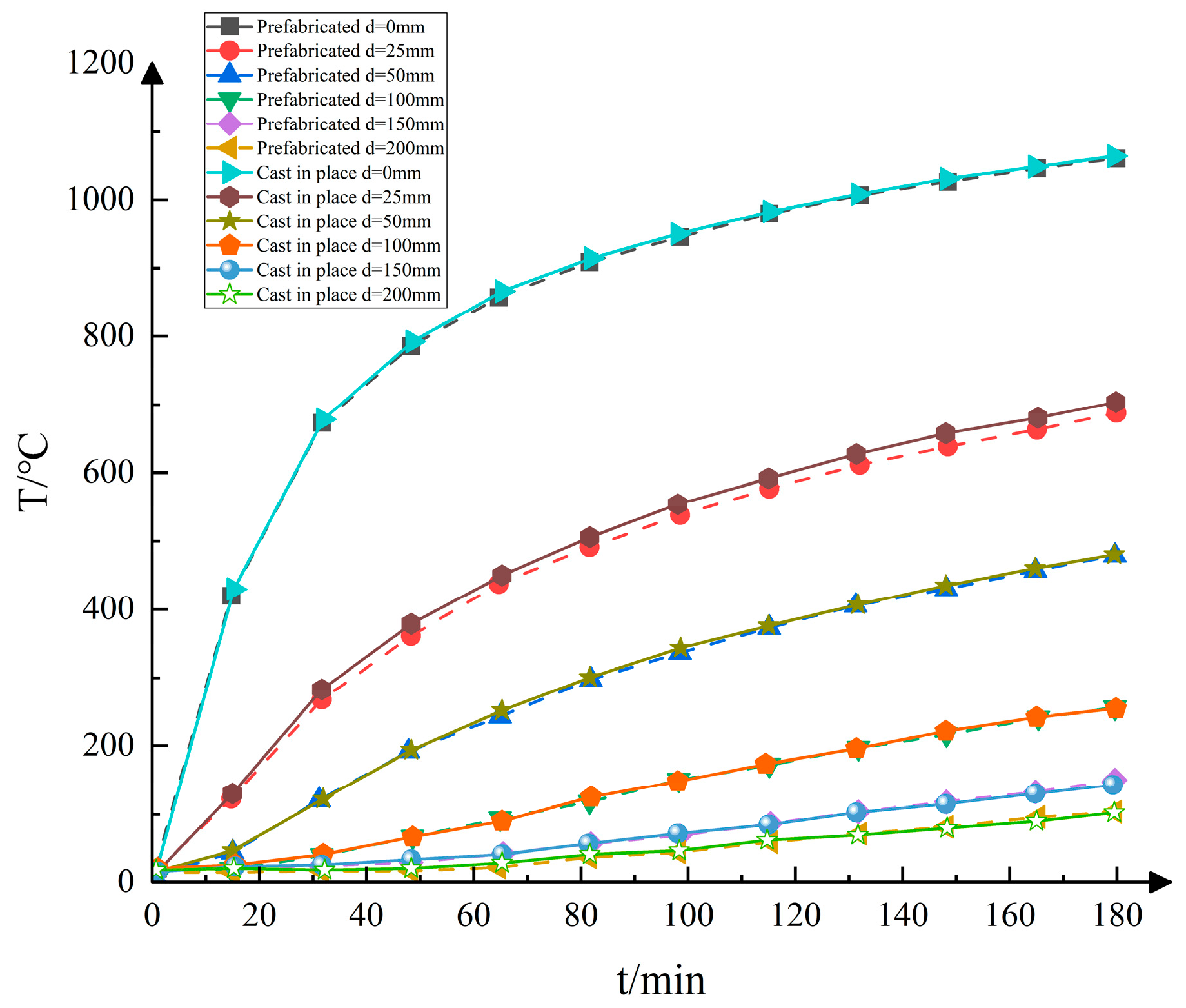
Figure 13 displays the temperature-time curves for prefabricated and cast-in-place shear walls connected by sleeve grouting, after three hours of one-sided fire exposure. As illustrated in Figure 13, the internal temperature fields of both specimens demonstrate a similar temporal evolution. During the initial fire exposure phase, the thermal inertia of concrete is evident, resulting in a rapid temperature increase in the region adjacent to the exposed surface (within 0–100 mm) and the formation of a pronounced temperature gradient. In contrast, the temperature rise on the unexposed (fire-back) side is significantly delayed, remaining close to the initial temperature for approximately 20 min after fire onset, before gradually increasing.
Figure 13.
Specimen temperature-time curve.
Table 4 presents the average temperatures of cross-sections in both sleeve-grouted prefabricated shear walls and cast-in-place shear walls under single-sided fire exposure over varying durations. The data indicate that the average temperature at measurement points located 0 mm, 25 mm, 50 mm, 100 mm, 150 mm, and 200 mm from the exposed surface increases with prolonged fire exposure, though the rate of temperature rise diminishes over time. Furthermore, under identical exposure conditions, the sections of the prefabricated shear wall near the fire-exposed surface demonstrate lower average temperatures compared to those of the cast-in-place shear wall, whereas the opposite is observed on the unexposed (back) side, where the prefabricated specimens show higher temperatures. This phenomenon can be ascribed to the monolithic characteristic of cast-in-place shear walls. Their higher density and superior structural continuity allow for heat to be conducted more efficiently and directly. In contrast, the inherent construction features of sleeve-grouted prefabricated shear walls, like interfacial discontinuities, may impede heat transfer, leading to thermal accumulation within the wall and consequently higher internal and rear-side temperatures.
Table 4.
Average Temperatures of Specimen Sections under Different exposure Times (Unit: °C).
3.2. Analysis of Fire Resistance Performance
Based on the validation of the thermodynamic coupling analysis model, a fire resistance performance assessment model was developed for prefabricated shear walls connected via sleeve grouting. The fire resistance behavior of the specimen under single-sided fire exposure for three hours, with an axial compression ratio of 0.2, was evaluated, and differences in fire resistance performance between the prefabricated and cast-in-place shear walls were systematically analyzed.
- Deformation Analysis
- (1)
- Overall deformation assessment
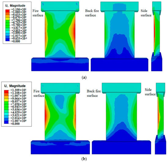
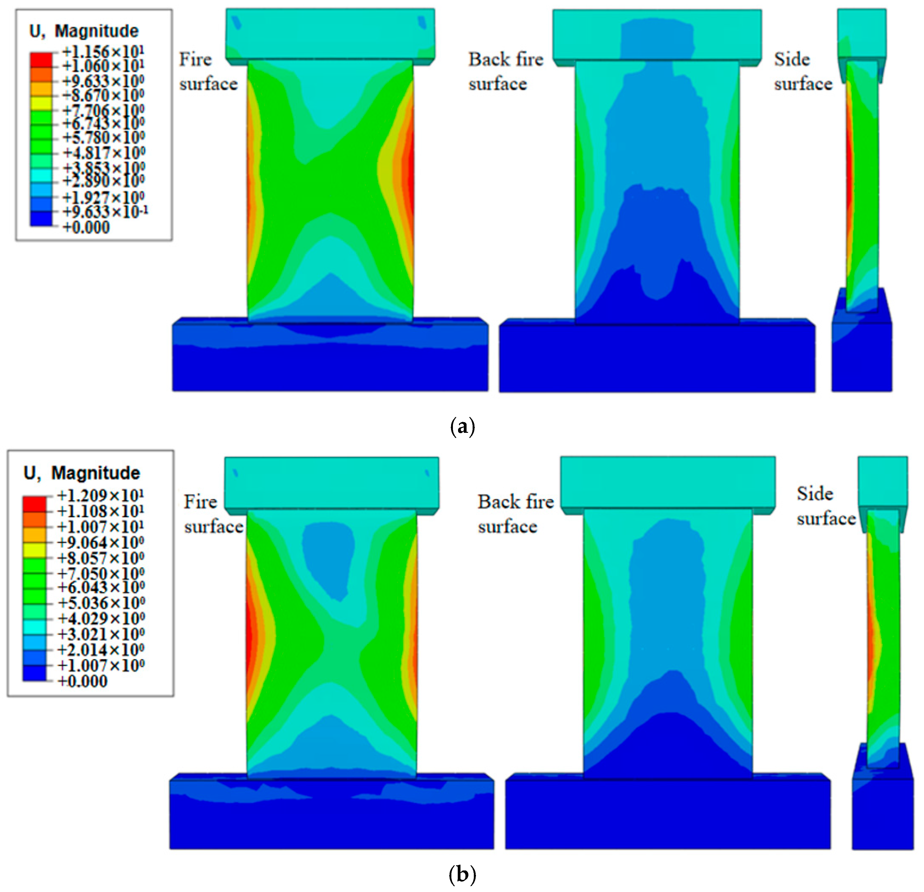
Figure 14 displays the deformation cloud diagram of a specimen subjected to one-sided fire exposure for 3 h. As illustrated in the figure, under the combined influence of fire and applied load, the deformation behavior of the prefabricated shear wall connected to the cast-in-place wall via sleeve grouting generally aligns with that of the cast-in-place wall, characterized by an overall outward deflection toward the fire-exposed side. However, the prefabricated shear wall exhibits slightly greater out-of-plane deformation in the sleeve region on the unexposed (backfire) side compared to the cast-in-place wall. This phenomenon can be primarily attributed to the presence of sleeve grouting connection joints, which, under elevated temperatures, result in composite action between the grout material and the steel sleeve, thereby restricting the wall’s deformation capacity in that region.
Figure 14.
Overall deformation diagram of the specimen: (a) Cast-in-place shear wall; (b) Prefabricated shear walls connected by sleeve grouting.
- (2)
- Axial deformation
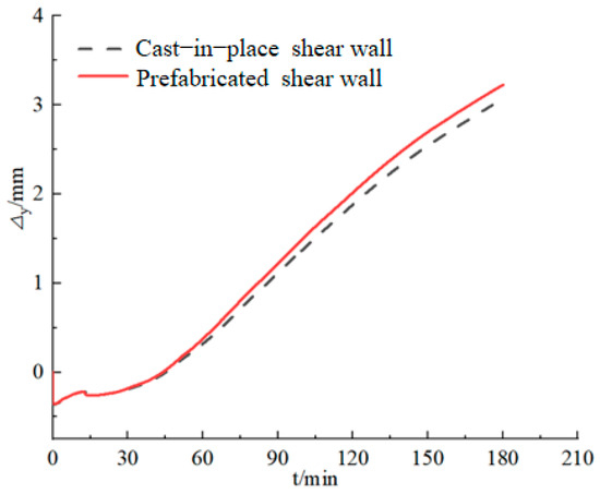
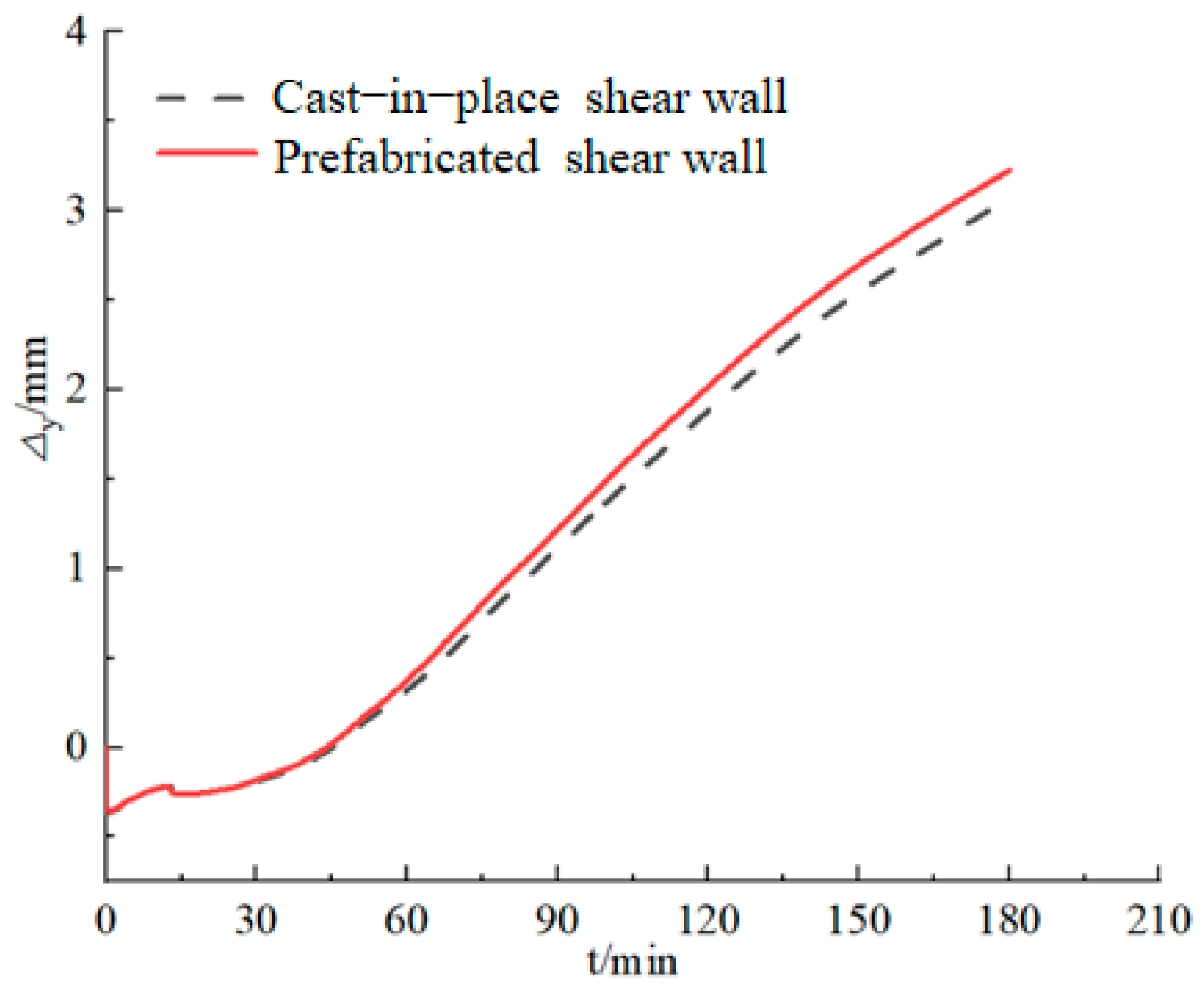
Figure 15 shows the axial displacement-time curve of a specimen subjected to 3 h of one-sided fire exposure. As illustrated in the figure, the temporal variation trend of axial displacement for the prefabricated shear wall connected via sleeve grouting generally aligns with that of the cast-in-place wall. During the fire exposure, thermal expansion of the materials became increasingly significant, causing upward axial displacement in both walls. After 3 h of fire exposure, the measured axial displacements were 3.07 mm and 3.75 mm for the respective specimens.
Figure 15.
Axial displacement-time curve.
- (3)
- Lateral Deformation
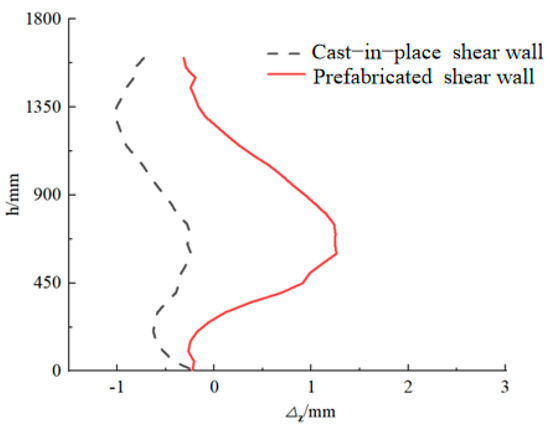
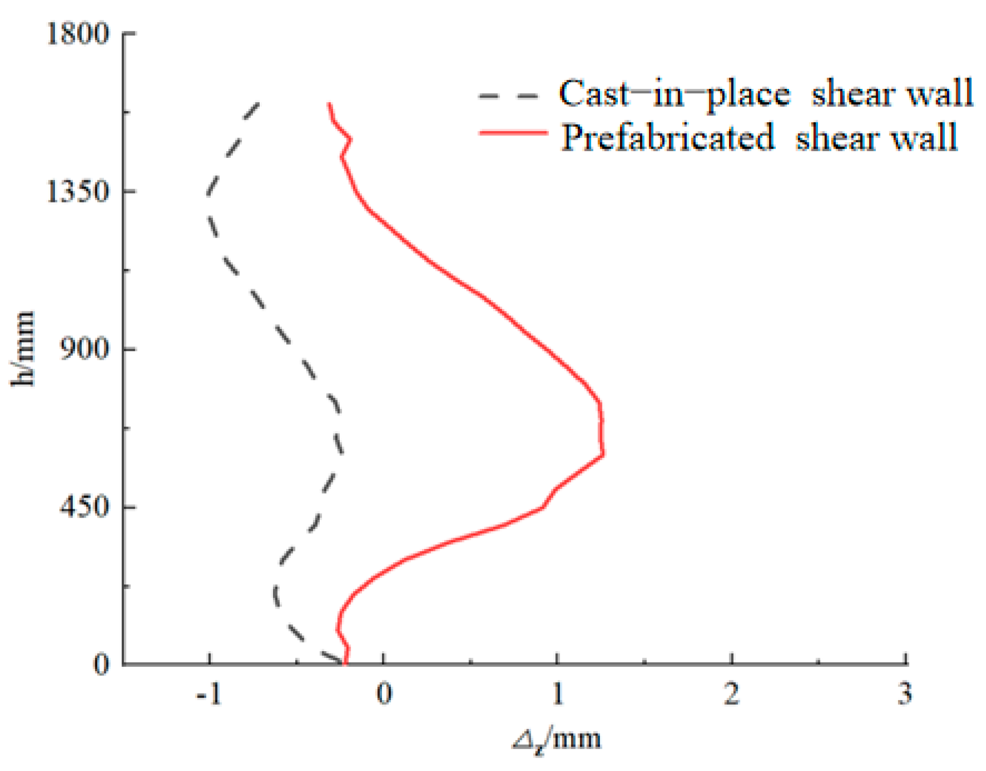
Figure 16 displays the lateral deformation curve along the wall height direction on the unexposed side of the specimen subjected to 3 h of one-sided fire exposure (Lateral deformation refers to the variation curve of the lateral deflection of the face along the height of the wall. Due to the consolidation at the base of the wall and the release of only axial displacement at the top of the wall, the in-plane horizontal deformation can be ignored). As illustrated in the figure, the lateral deformation behavior of the prefabricated shear wall with sleeve grouting connections is generally consistent with that of the cast-in-place shear wall. Morphologically, the upper portion of the wall deflects toward the fire-exposed side. Notably, greater lateral deformation is observed in the prefabricated shear wall compared to the cast-in-place counterpart, with maximum displacements recorded at −0.24 mm and 1.25 mm, respectively. This difference is primarily attributed to the presence of sleeves, which result in higher internal temperatures within the specimen and more pronounced deterioration of material properties, thereby increasing its susceptibility to deformation under combined fire and vertical loading conditions.
Figure 16.
Lateral deformation–time curve.
- 2.
- Distribution of the Temperature Field
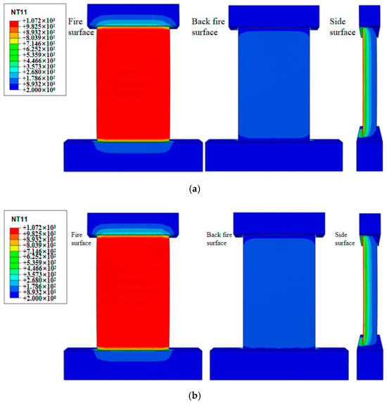
Figure 17 displays the temperature field distribution cloud map of a specimen subjected to a one-sided fire exposure for 3 h. As illustrated in the figure, under the combined influence of fire and mechanical loading, the temperature field distributions of the sleeve-grouted prefabricated shear wall and the cast-in-place shear wall are generally similar. Temperature distribution is relatively uniform on both the fire-exposed and fire-backed sides, with higher temperatures observed in the central region of the wall and lower temperatures at the edges. A gradient temperature profile is evident across the cross-section, gradually decreasing from the fire-exposed side to the fire-backed side. Notably, a discernible difference is observed in the extent of the high-temperature zone between the two wall types, with the sleeve-grouted prefabricated shear wall exhibiting a larger high-temperature area compared to the cast-in-place shear wall.
Figure 17.
Cloud map of the temperature field distribution of the specimen: (a) Cast-in-place shear wall; (b) Prefabricated shear walls connected by sleeve grouting.
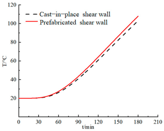
Figure 18 presents the temperature–time curve for the rear side of a shear wall subjected to a one-sided fire exposure for 3 h. As illustrated in the figure, the temperature evolution trend on the unexposed side of the prefabricated shear wall connected via sleeve grouting aligns with that of the cast-in-place shear wall. The temperature on the unexposed side rises progressively with extended fire exposure, with the prefabricated shear wall recording slightly higher temperatures. After 3 h of exposure, maximum temperatures of 103.00 °C and 107.92 °C were recorded on the unexposed side of the cast-in-place and prefabricated shear walls, respectively.
Figure 18.
Temperature–time curve on the backfire side.
- 3.
- Fire Resistance Performance Evaluation
- (1)
- Basis for Evaluation
According to the technical requirements of the “Test Method for Fire Resistance of Building Components” [34], the determination of the fire resistance limit of reinforced concrete shear walls under fire action must simultaneously meet the three criteria of bearing capacity (stability), integrity and thermal insulation. These three criteria are used to determine the limit state of the load-bearing capacity of load-bearing walls under standard fire conditions. Equations (9) and (10), respectively, correspond to the deflection limit and the rate limit of the flexural member. Equations (11) and (12) specify the critical values of axial compression deformation and deformation rate for axially compressed members. When any indicator is exceeded, it is considered that the component has lost its load-bearing capacity. This study directly cites the above-mentioned normative limit values as the criterion for the fire resistance limit in numerical simulation.
Load-bearing capacity (stability) is defined as the duration a specimen can maintain its structural integrity under load during a fire resistance test, as assessed by deformation and its rate. A specimen is considered to have lost its load-bearing capacity if it exceeds the prescribed limits for any of the following criteria.
In the formula, L denotes the net span of the specimen, expressed in millimeters (mm). The parameter d represents the distance between the compressive and tensile points on the specimen’s cross-section, also measured in millimeters (mm). The variable h denotes the initial height of the specimen, with units in millimeters (mm).
Integrity refers to the duration for which the specimen can continuously sustain its fire resistance and fire insulation performance during the fire resistance test. The specimen is regarded as having lost integrity if any of the following conditions are met: ignition of the cotton pad, passage of the gap probe through the specimen, or the appearance of flames on the unexposed side lasting more than 10 s.
Thermal insulation indicates the period during which the specimen retains its ability to resist heat transfer when exposed to fire. The specimen is deemed to have failed in thermal insulation if either of the following temperature rise criteria is exceeded on the unexposed side: the average temperature surpasses the initial average temperature by 140 °C, or the temperature at any single measurement point increases by more than 180 °C above its initial value.
- (2)
- Fire Resistance Rating Analysis
When the finite element method is applied to fire resistance performance analysis, direct assessment of a component’s structural integrity is not achievable. As a result, the determination of a component’s fire resistance limit is mainly dependent on evaluations of its load-bearing capacity and thermal insulation performance.
In this study, for prefabricated shear walls connected via sleeve grouting, loss of load-bearing capacity (stability) is considered to have occurred when the ultimate axial compression deformation reaches 16.00 mm or the maximum rate of axial compression deformation reaches 4.80 mm/min. Loss of insulation performance is identified when the average temperature on the unexposed face exceeds 160 °C or the temperature at any individual measurement point reaches 180 °C. Under standard one-sided fire exposure conditions lasting three hours, the average backside temperatures of the prefabricated shear wall and the cast-in-place shear wall connected by sleeve grouting were recorded as 107.92 °C and 103.00 °C, respectively—both below the threshold of 160 °C, thus satisfying the insulation criteria. The corresponding axial deformations were measured at 3.75 mm and 3.07 mm, both within the prescribed limits, indicating that load-bearing capacity (stability) was maintained. Therefore, under an axial compression ratio of 0.2 and one-sided fire exposure for three hours, neither the sleeve-grouted prefabricated shear wall nor the cast-in-place counterpart reached its fire resistance limit. Both wall types exhibited satisfactory fire resistance performance, complying with the requirements for a Class I fire resistance rating (3 h) as specified in the “Code for Fire Protection Design of Buildings” [30].
4. Parametric Analysis
To delve deeper into the fire resistance performance of prefabricated shear walls connected by sleeve grouting, a comprehensive parametric analysis is carried out in this chapter, based on a validated finite element model. The parameters under scrutiny encompass axial compression ratio, longitudinal reinforcement diameter, concrete cover thickness, and sleeve length. The study pinpoints the key factors and reveals the underlying trends that influence the fire resistance behavior of sleeve-grouted prefabricated shear walls.
4.1. Axial Compression Ratio
To explore the fire resistance performance of prefabricated shear walls connected by sleeve grouting under different axial compression ratios, their behavior is simulated under realistic service conditions when exposed to fire on various floors. Specimens W1-N2, W1-N3, W1-N4, W1-N5, and W1-N6, which are prefabricated shear wall components connected via sleeve grouting with axial compression ratios of 0.2, 0.3, 0.4, 0.5, and 0.6, respectively, are used. All specimens are subjected to one-sided fire exposure for three hours, while the other parameters remain consistent with those specified in Section 2.1.
- Axial Deformation
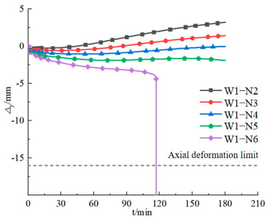
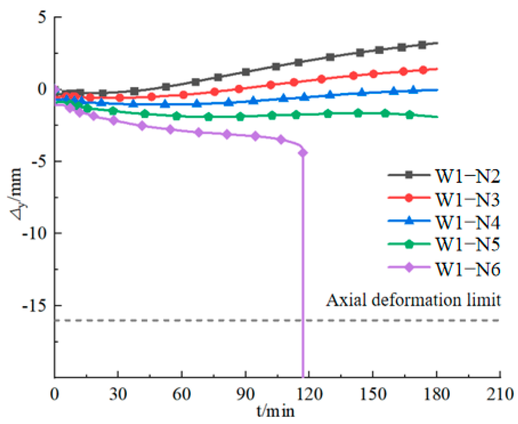
The axial displacement–time curves of each specimen under different axial compression ratios after 3 h single-sided fire exposure are depicted in Figure 19. As shown in the figure, the axial compression ratio significantly influences the axial deformation behavior of the sleeve-grouted prefabricated shear walls. A higher axial compression ratio leads to more significant compressive deformation and larger axial displacement under mechanical loading. Specifically, after 3 h of fire exposure, axial displacements of specimens W1-N2 to W1-N5 were recorded as 3.22 mm, 1.42 mm, −0.02 mm, and −1.91 mm, respectively. Specimen W1-N6, however, experienced instability failure at 117 min into the fire test. When the axial compression ratio is below 0.4, axial deformation remains positive, showing that displacement caused by thermal expansion outweighs that resulting from compression-induced shortening. In contrast, when the axial compression ratio is 0.4 or higher, the axial deformation becomes negative, indicating that the displacement caused by axial compression surpasses that induced by thermal expansion.
Figure 19.
Axial displacement-time curve of the specimen.
- 2.
- Lateral Deformation
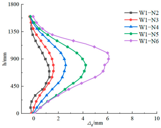
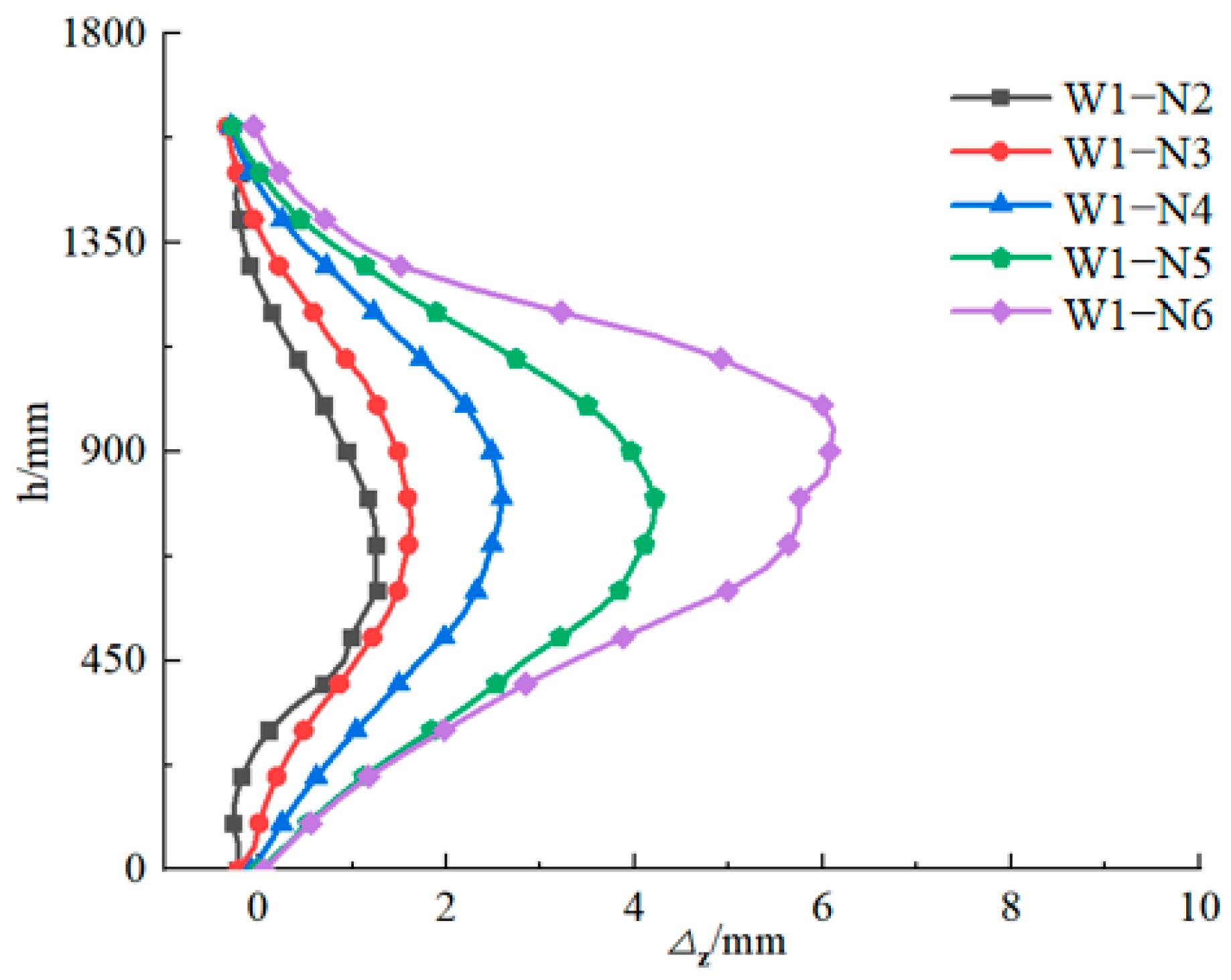
Figure 20 displays the lateral deformation profiles on the rear surface of specimens with different axial compression ratios along the wall height, following 3 h of one-sided fire exposure. It can be observed that the axial compression ratio significantly influences both the lateral deformation magnitude and the location of maximum deformation in prefabricated shear walls connected via sleeve grouting. As the axial compression ratio rises, the lateral deformation of the specimens increases progressively at an accelerating rate. Concurrently, the position of maximum deformation moves upward with higher axial compression ratios. Specifically, after 3 h of fire exposure, maximum lateral deformations of specimens W1-N2 to W1-N5 were recorded as 1.25 mm, 1.62 mm, 2.59 mm, and 4.22 mm, respectively. In contrast, specimen W1-N6 failed after only 17 min of exposure, with a maximum lateral deformation of 6.11 mm recorded at the time of failure.
Figure 20.
The lateral deformation curve of the backfire side of the specimen along the wall height direction.
- 3.
- Fire Resistance Limit
Table 5 provides a summary of the fire resistance limits of the specimens subjected to different axial compression ratios. It is revealed by the data that, after being exposed to one-sided fire for 3 h, only specimen W1-N6 reached its fire resistance limit due to the loss of load-bearing capacity (structural instability), with a fire resistance limit of 117 min being recorded. The other specimens retained adequate load-bearing capacity (stability) and thermal insulation performance, meeting the requirements for a Class I fire resistance rating (3 h) for walls as stipulated in the “Code for Fire Protection Design of Buildings” [30].
Table 5.
Fire resistance limit of specimens under different coaxial pressure ratios.
The aforementioned results indicate that as the axial compression ratio increases, the axial deformation of the wall transitions from positive to negative, while the lateral deflection continues to increase. This phenomenon can be primarily attributed to the following mechanisms: when the axial compression ratio is less than 0.4, the thermal expansion displacement of the wall is greater than the axial compression displacement, ensuring good structural stability; however, when the axial compression ratio reaches or exceeds 0.4, the axial compression displacement surpasses the thermal expansion displacement. The continuous amplification of lateral deflection stems from the rapid degradation of concrete’s elastic modulus and compressive strength during the fire heating process, which leads to a reduction in effective axial stiffness. Meanwhile, the combined effects of the reduced flexural stiffness and the additional bending moment induced by the temperature gradient result in a significant increase in the out-of-plane deflection of the wall along its thickness direction. Overall, the increase in axial compression ratio impairs the overall stability of the wall under thermo-mechanical coupling effects.
4.2. Diameter of the Longitudinal Rib
W2-D10 to W2-D16 denote sleeve-grouted prefabricated shear wall specimens with longitudinal reinforcement diameters of 10 mm, 12 mm, 14 mm, and 16 mm, respectively. All specimens were subjected to single-sided fire exposure for a duration of 3 h. The parameters of the remaining components remain consistent with those specified in Section 2.1.
- Axial Deformation
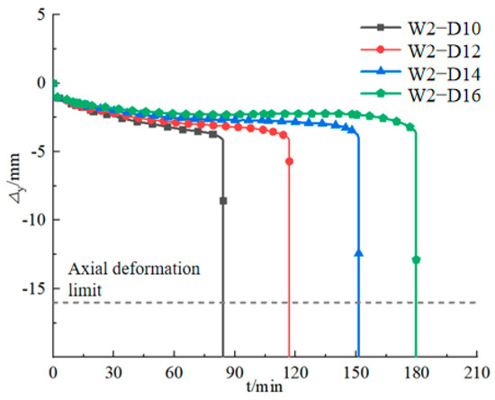
Figure 21 displays the axial displacement-time curves of specimens with varying longitudinal bar diameters under 3 h unilateral fire exposure. As illustrated, the diameter of the longitudinal reinforcement significantly affects the axial deformation behavior of the sleeve-grouted prefabricated shear walls. Before fire exposure, consistent axial displacement trends were observed across all specimens during the initial 10 min period. Thereafter, axial displacement increased progressively with exposure time, with specimens having smaller-diameter reinforcement experiencing greater axial deformation. Under 3 h fire exposure, specimens with longitudinal bar diameters of 10 mm, 12 mm, 14 mm, and 16 mm reached the code-specified axial compression deformation limit of 16 mm at 84 min, 117 min, 151 min, and 179 min, respectively. For each 2 mm increment in bar diameter, the time required to reach the deformation limit increased by 39.29%, 29.06%, and 17.61%, respectively.
Figure 21.
Axial displacement-time curve of the specimen.
- 2.
- Lateral Deformation
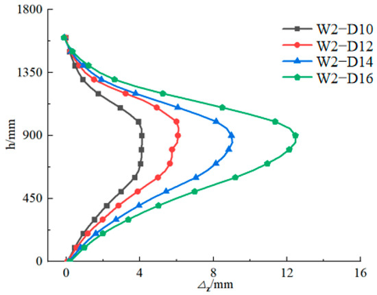
Figure 22 presents the lateral deformation curves on the rear surface of specimens with varying longitudinal rib diameters, measured along the wall height direction after a one-sided fire exposure lasting 3 h. It is revealed that the diameter of the longitudinal reinforcement has a substantial impact on the lateral deformation behavior of sleeve-grouted prefabricated shear walls. As the diameter of the longitudinal bars increases, the magnitude of lateral deformation also rises. Specifically, the maximum lateral deformations at failure for specimens W2-D10 to W2-D16 were recorded as 4.12 mm, 6.11 mm, 8.98 mm, and 12.46 mm, respectively. With each 2 mm increment in bar diameter, the maximum lateral deformation was found to increase by 48.30%, 46.97%, and 38.75%, respectively.
Figure 22.
The lateral deformation curve of the backfire side of the specimen along the wall height direction.
- 3.
- Fire Resistance Limit
Table 6 summarizes the fire resistance limits of specimens with different longitudinal bar diameters. The data demonstrate that the diameter of the longitudinal reinforcement has a notable influence on the fire resistance limit of the shear walls; specifically, larger bar diameters correspond to longer fire resistance durations. The thermal insulation performance of all tested prefabricated shear wall specimens was satisfactory. All specimens (W2-D10 to W2-D16) reached their fire resistance limit due to loss of load-bearing capacity (structural instability), with corresponding fire resistance times of 84 min, 117 min, 151 min, and 179 min, respectively.
Table 6.
Fire resistance limits of specimens with different longitudinal rib diameters.
The aforementioned results demonstrate that as the diameter of longitudinal reinforcement increases, the rate of axial compressive deformation of the wall decreases, while the lateral deflection increases conversely, and the fire resistance limit is prolonged. This is mainly due to the fact that the high-temperature degradation of steel reinforcement is slower than that of concrete; increasing the diameter enhances the proportion of steel area and improves the axial stiffness, thereby mitigating axial deformation. However, the simultaneous increase in flexural stiffness amplifies the additional curvature induced by the temperature gradient, leading to the enlargement of out-of-plane deflection. Therefore, the increase in the diameter of longitudinal reinforcement simultaneously reduces axial deformation and intensifies lateral deformation.
4.3. Sleeve Length
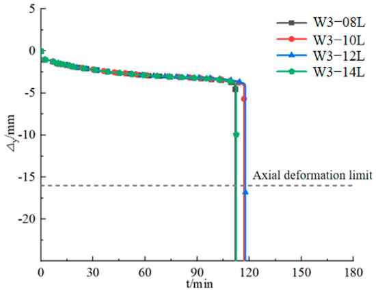
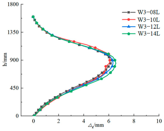
As a crucial component of prefabricated shear walls, the length of sleeve connectors may impact the structural performance of specimens when exposed to fire. This section therefore investigates the fire-resistance behavior of specimens with four distinct sleeve lengths. Specimens W3-08L to W3-14L represent sleeve grouted prefabricated shear wall components with sleeve lengths of 0.8 L, 1.0 L, 1.2 L, and 1.4 L, respectively (where L = 245 mm). All specimens were subjected to single-sided fire exposure for a duration of 3 h, with other parameters kept consistent with those specified in Section 2.1.
- Axial Deformation
Figure 23 presents the axial displacement–time curves of specimens with varying sleeve lengths subjected to one-sided fire exposure for a duration of 3 h. As depicted in the figure, a relatively minor influence on the axial displacement behavior of the specimens is exerted by the sleeve length. Consistent overall trends in axial displacement are observed among specimens with varying sleeve lengths, with axial deformation being progressively increased as the duration of fire exposure increases. The times required for specimens W3-08L, W3-10L, W3-12L, and W3-14L to reach the fire resistance limit under one-sided heating were 111 min, 117 min, 118 min, and 112 min, respectively. When the sleeve length was increased from 0.8 L to 1.0 L, the time taken to reach the axial compression deformation limit was extended by 7 min; further increasing the length to 1.2 L resulted in an additional 1 min extension. However, when the sleeve length was increased to 1.4 L, the time reduced by 5 min compared to the 1.2 L case. This suggests that an appropriate increase in sleeve length can, to a certain extent, enhance the overall structural stability of the specimen, thereby improving its ability to withstand prolonged high-temperature exposure during a fire without rapidly reaching the fire resistance failure criterion.
Figure 23.
Axial displacement–time curve of the specimen.
- 2.
- Lateral deformation
Figure 24 displays the lateral deformation curves on the unexposed side of specimens with different sleeve lengths, which were subjected to a one-sided fire exposure for 3 h, plotted along the wall height direction. As demonstrated in the figure, the sleeve length has a relatively minor impact on the lateral deformation of sleeve-grouted prefabricated shear walls. With increasing sleeve length, the overall lateral deformation of the specimens exhibits a slight upward trend. Specifically, the maximum lateral deformations at failure for specimens W3-08L, W3-10L, W3-12L, and W3-14L were 6.12 mm, 6.11 mm, 6.34 mm, and 6.56 mm, respectively.
Figure 24.
The lateral deformation curve of the backfire side of the specimen along the wall height direction.
- 3.
- Fire resistance limit
Table 7 provides a summary of the fire resistance limits for specimens with different sleeve lengths. The data reveal that, within the tested range, sleeve length has a limited effect on the fire resistance performance of the wall. Notably, an increase in sleeve length is associated with a marginal reduction in fire resistance time. Prefabricated shear walls with all sleeve configurations demonstrated satisfactory thermal insulation performance. In all cases, the fire resistance limit was reached when the specimens lost their load-bearing capacity (i.e., structural stability). The fire resistance limits measured for specimens W3-08L, W3-10L, W3-12L, and W3-14L were 111 min, 117 min, 118 min, and 112 min, respectively.
Table 7.
Fire resistance Limits of specimens with different sleeve lengths.
The aforementioned results indicate that the sleeve length has a minor influence on the fire resistance performance of precast shear walls with sleeve grouting connections. Within the range of 0.8 L to 1.4 L, all specimens exhibit a consistent trend in axial displacement, a slight increase in lateral deformation, and the fire resistance limit only fluctuates between 111 and 118 min. All specimens reach the limit state due to the loss of bearing capacity while maintaining excellent thermal insulation. This is mainly because within this length range, there is no significant change in the thermal conductivity of the sleeve or the mechanical stiffness of the wall, and further increasing the sleeve length provides no continuous gain in performance.
4.4. Thickness of the Protective Layer
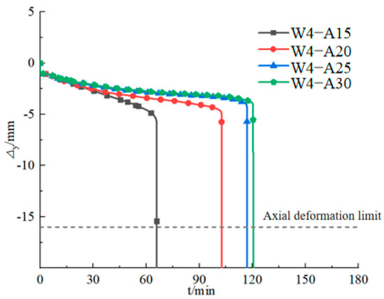
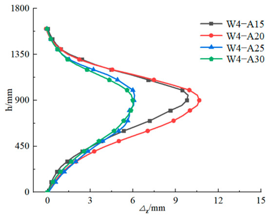
The thickness of the protective concrete cover over reinforcing bars is a critical parameter influencing the fire resistance performance of structural components. An adequate cover thickness can effectively mitigate the deterioration of the mechanical properties of reinforcement at elevated temperatures, thereby maintaining structural stability during fire exposure. According to relevant standards [35], the minimum thickness of the concrete cover for outer reinforcing bars in the sleeve connection zones of prefabricated shear wall structures should be no less than 15 mm to meet design requirements. In this study, four different cover thicknesses were designed for investigation, with specimens W4-A15 to W4-A30 having protective layer thicknesses of 15 mm, 20 mm, 25 mm, and 30 mm, respectively. All specimens were exposed to single-sided fire for 3 h, with other parameters kept consistent with those in Section 2.1.
- Axial Deformation
Figure 25 displays the lateral deformation curves on the unexposed side of specimens with different protective layer thicknesses, subjected to one-sided fire exposure for 3 h, plotted along the wall height direction. As illustrated in the figure, the thickness of the protective layer significantly influences the lateral deformation behavior of prefabricated shear walls connected via sleeve grouting. With an increase in protective layer thickness, the lateral deformation first rises and then falls. Specifically, the maximum lateral deformations at failure for specimens W4-A15 to W4-A30 were recorded as 9.87 mm, 10.66 mm, 6.11 mm, and 6.02 mm, respectively.
Figure 25.
Axial displacement–time curve of the specimen.
- 2.
- Lateral deformation
Figure 26 presents the lateral deformation curves on the unexposed side of specimens with varying protective layer thicknesses, subjected to one-sided fire exposure for 3 h, plotted along the wall height direction. As illustrated in the figure, the thickness of the protective layer significantly influences the lateral deformation behavior of prefabricated shear walls connected via sleeve grouting. With increasing protective layer thickness, the lateral deformation initially increases and subsequently decreases. Specifically, the maximum lateral deformations at failure for specimens W4-A15 to W4-A30 were recorded as 9.87 mm, 10.66 mm, 6.11 mm, and 6.02 mm, respectively.
Figure 26.
The lateral deformation curve of the backfire side of the specimen along the wall height direction.
- 3.
- Fire resistance limit
Table 8 provides a summary of the fire resistance limits for specimens with different protective layer thicknesses. The data reveal that the thickness of the protective layer significantly affects the fire resistance performance of sleeve-grouted prefabricated shear walls. A general trend is evident: greater protective layer thickness corresponds to longer fire resistance limits, although the rate of increase diminishes with further thickening. The thermal insulation performance of all tested specimens was satisfactory. All specimens reached their fire resistance limit upon loss of load-bearing capacity (structural stability). The fire resistance limits for specimens W4-A15 to W4-A30 were 66 min, 102 min, and 117 min, respectively.
Table 8.
Fire resistance Limits of specimens with different protective layer thicknesses.
The aforementioned results demonstrate that as the thickness of the protective layer increases, the fire resistance limit is prolonged, the rate of axial compression decreases, and the lateral deformation exhibits a trend of first increasing and then decreasing. This is mainly because an increase in the protective layer thickness enhances thermal resistance and reduces the rate of temperature rise in the reinforcement, thereby delaying the degradation of reinforcement strength and maintaining the axial stiffness of the cross-section, which is manifested by a significant reduction in axial compressive deformation. Meanwhile, a larger protective layer thickness tends to flatten the temperature gradient distribution across the cross-section, reducing the expansion difference between the fire-exposed surface and the unexposed surface. This leads to a decrease in cross-sectional curvature and a subsequent reduction in out-of-plane deflection. Therefore, increasing the thickness of the protective layer can effectively improve the fire resistance performance of the wall.
4.5. High Thickness Ratio
Specimens W5-H5, W5-H8, and W5-H10 are prefabricated shear walls with height-to-thickness ratios of 5, 8, and 10, respectively, connected via sleeve grouting. Each underwent a single-sided fire exposure lasting 3 h. All other parameters adhered to those outlined in Section 2.1.
- Axial Deformation
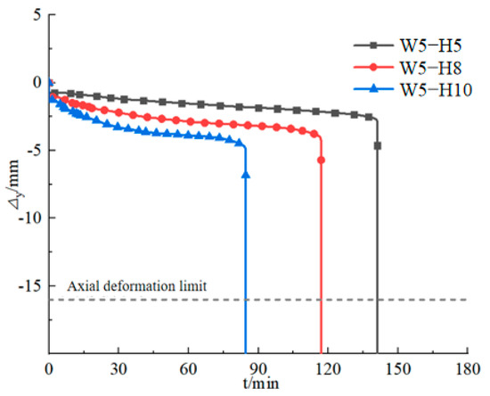
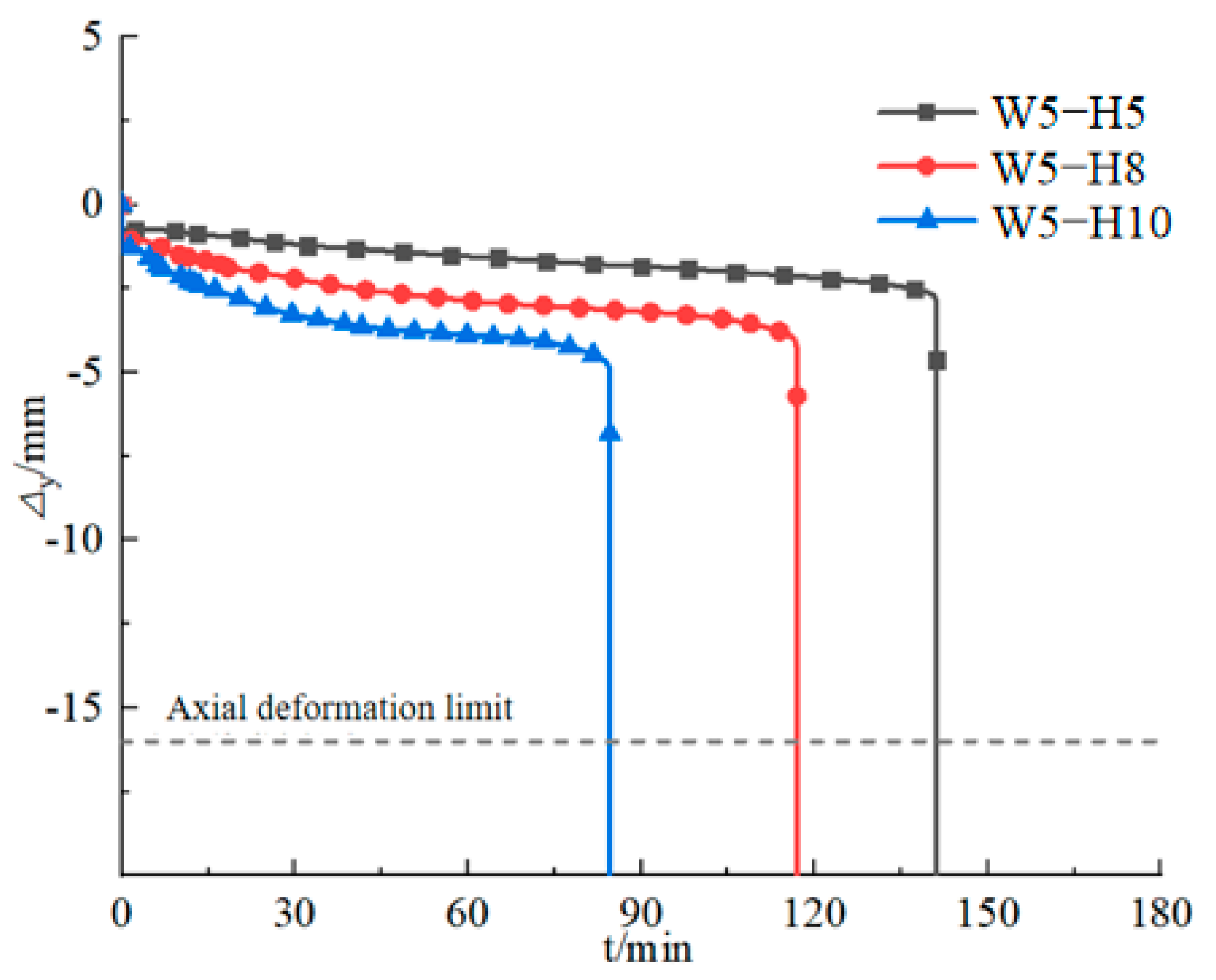
Figure 27 presents the axial displacement–time curves of specimens with different height-to-thickness ratios under 3 h unilateral fire exposure. As depicted in the figure, the axial displacement is significantly influenced by the height-to-thickness ratio. The overall trend of axial deformation is a continuous increase over time until structural failure occurs, with higher deformation observed in specimens with larger height-to-thickness ratios. During the 3 h fire exposure, the axial displacements of specimens W5-H5, W5-H8, and W5-H10 reached the specified axial compression deformation limit of 16 mm at 141 min, 117 min, and 89 min, respectively. Compared to W5-H5, the times to reach the deformation limit were reduced by 17.02% and 36.88% for W5-H8 and W5-H10, respectively.
Figure 27.
Axial displacement–time curve of the specimen.
- 2.
- Lateral deformation
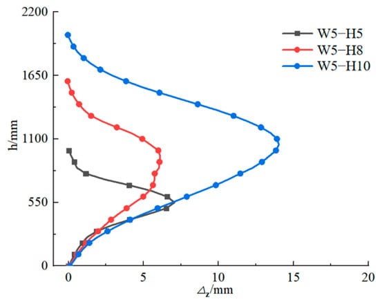
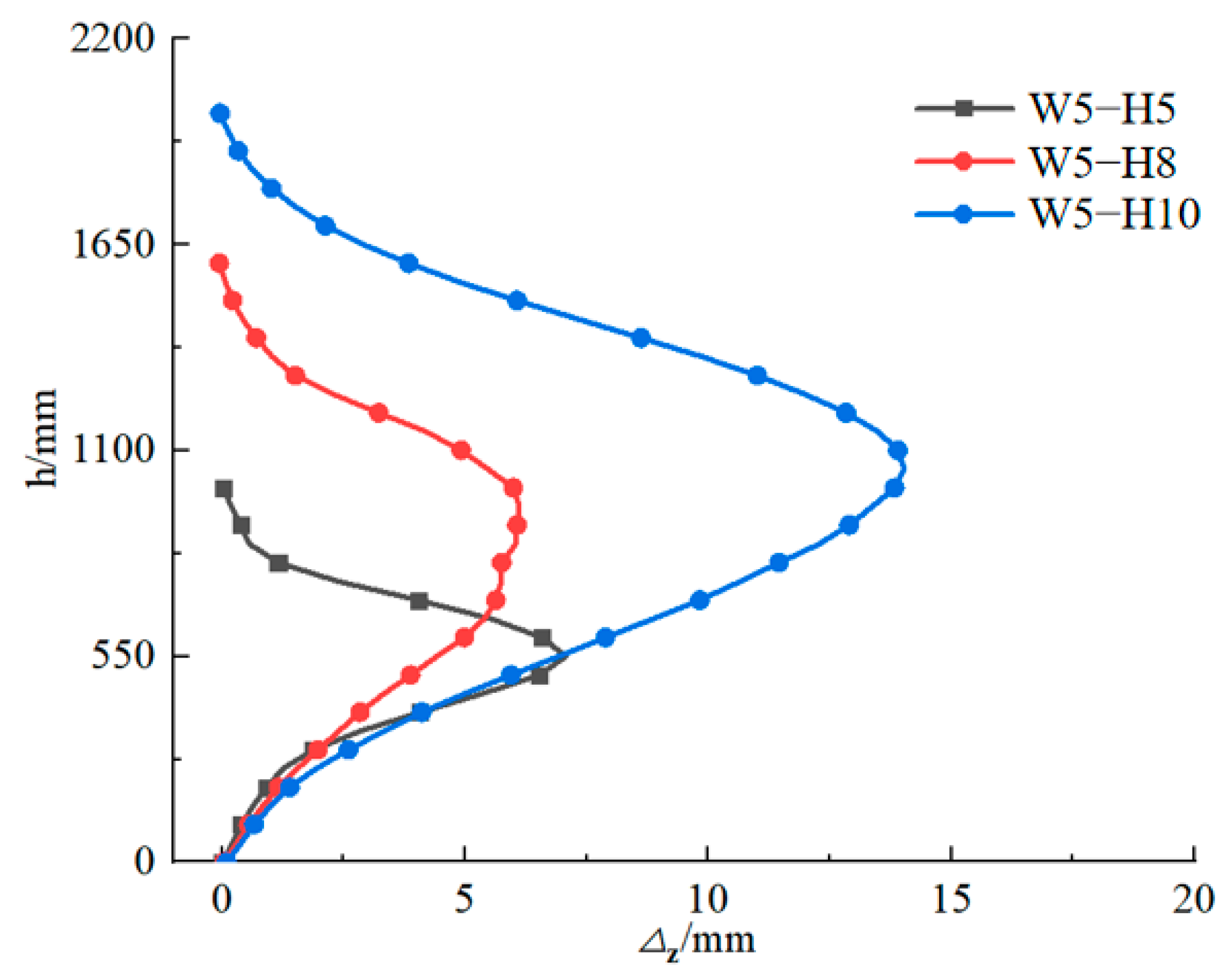
Figure 28 displays the lateral deformation curves on the unexposed side of specimens with varying height-to-thickness ratios, subjected to one-sided fire exposure for 3 h, plotted along the wall height direction. As illustrated in the figure, the height-to-thickness ratio exerts a significant influence on the lateral deformation behavior of sleeve-grouted prefabricated shear walls. With an increase in the height-to-thickness ratio, the lateral deformation first decreases and then increases. Specifically, the maximum lateral deformations at failure for specimens W5-H5, W5-H8, and W5-H10 were recorded as 7.07 mm, 6.11 mm, and 14.03 mm, respectively.
Figure 28.
The lateral deformation curve of the backfire side of the specimen along the wall height direction.
- 3.
- Fire resistance limit
Table 9 provides a summary of the fire resistance limits for specimens with different height-to-thickness ratios. The data indicate that the height-to-thickness ratio has a notable effect on the fire resistance performance of the walls, with higher ratios generally corresponding to longer fire resistance durations. Satisfactory thermal insulation performance was demonstrated by all tested prefabricated shear walls. All specimens W5-H5, W5-H8, and W5-H10 reached their fire resistance limit due to loss of load-bearing capacity (structural instability), with measured fire resistance times of 141 min, 117 min, and 89 min, respectively.
Table 9.
Fire resistance Limits of test pieces with different height-to-thickness ratios.
The aforementioned results indicate that as the aspect ratio increases, the rate of axial compression accelerates, the lateral deflection first decreases and then increases, and the fire resistance limit is significantly shortened. This is mainly because the increase in aspect ratio reduces the flexural stiffness of the wall cross-section and the out-of-plane stability bearing capacity. Under the action of one-sided fire, the additional bending moment induced by the temperature gradient leads to a rapid amplification of out-of-plane deflection. Meanwhile, the axial compression path of the longer wall pier is lengthened, resulting in a faster rate of axial deformation. Therefore, with the increase in aspect ratio, both the axial and lateral deformations of the wall increase significantly, and the fire resistance limit decreases accordingly.
5. Conclusions
This study presents a numerical investigation into the fire resistance performance of prefabricated shear walls connected via sleeve grouting. The analysis focuses on key performance indicators under fire exposure, including deformation characteristics, lateral and axial deformations, temperature distribution, and fire resistance limits, along with a parametric study to evaluate influencing factors. The main survey results summary and design suggestions are as follows:
- Under conditions of single-sided fire exposure for a duration of three hours, the temperature distribution at mid-width and mid-height cross-sections of sleeve-grouted prefabricated shear walls generally follows the same pattern observed in cast-in-place shear walls, exhibiting arched and layered distributions, respectively, with temperature decreasing gradually from the exposed surface toward the unexposed side. However, due to the presence of sleeves, localized regions near the sleeve connections exhibit higher temperatures and expanded high-temperature zones compared to cast-in-place counterparts.
- Under identical fire exposure conditions, the deformation behavior of sleeve-grouted prefabricated shear walls is broadly similar to that of cast-in-place shear walls. Both types remain within acceptable deformation limits, with back-face temperatures below 160 °C, indicating adequate structural stability and thermal insulation performance that satisfy the requirements for a Class I fire resistance rating (3 h endurance). Nevertheless, prefabricated shear walls exhibit relatively greater axial and lateral deformations.
- Key parameters influencing the fire resistance performance of sleeve-grouted prefabricated shear walls include the axial compression ratio, longitudinal reinforcement diameter, concrete cover thickness, and height-to-thickness ratio. Specifically: among five specimens subjected to a 3 h single-sided fire exposure with axial compression ratios ranging from 0.2 to 0.6, only the specimen with a ratio of 0.6 reached the fire resistance limit; higher axial compression ratios correspond to increased axial and lateral deformations. For specimens with an axial compression ratio of 0.6, larger longitudinal bar diameters result in reduced axial deformation but increased lateral deformation—each 2 mm increment in bar diameter leads to increases in maximum lateral deformation by 48.30%, 46.97%, and 38.75%, respectively. Greater concrete cover thickness reduces axial deformation while generally increasing lateral deformation. As the height-to-thickness ratio increases, axial deformation increases monotonically, whereas lateral deformation initially decreases before subsequently increasing.
In this study, numerical simulations were conducted to investigate the temperature field distribution, deformation characteristics, and fire resistance performance of precast shear walls with sleeve grouting connections under one-sided fire exposure for 3 h. The results reveal that parameters such as axial compression ratio, longitudinal reinforcement diameter, sleeve length, protective layer thickness, and aspect ratio exert significant influences on the axial deformation, lateral deformation, and fire resistance limit of the walls. Given the significant temperature rise in the sleeve region under fire conditions, it is recommended to enhance fire protection measures in this area, such as adopting high-temperature resistant materials or adding thermal insulation layers, to improve the overall fire resistance performance of the walls. Such measures can effectively reduce the temperature in the sleeve region and mitigate the impact of fire on the wall structure. Additionally, during the design of precast shear walls, reasonable selection of parameters including axial compression ratio, longitudinal reinforcement diameter, and protective layer thickness can enhance the structural stability and fire resistance performance of the walls under fire conditions.
Author Contributions
Methodology, Y.W.; Software, W.D.; Validation, Y.W.; Formal analysis, X.L.; Investigation, W.D.; Data curation, H.W.; Writing—original draft, Y.W.; Writing—review & editing, Y.W. and W.D. All authors have read and agreed to the published version of the manuscript.
Funding
This research received no external funding.
Data Availability Statement
The original contributions presented in this study are included in the article. Further inquiries can be directed to the corresponding author.
Conflicts of Interest
The authors declare no conflicts of interest.
References
- Liu, H.; Chen, J.; Kong, P.; Du, X. Review on the seismic performance of precast assembled structures connected with grouted sleeves. Earthq. Eng. Eng. 2025, 45, 1–14. [Google Scholar]
- Ibrahim, O.O.; Imoudu, W.E.; Michael, D.; Chileshe, N. Building information modelling and green building certification systems: A systematic literature review and gap spotting. Sustain. Cities Soc. 2022, 81, 103865. [Google Scholar] [CrossRef] [Scilit]
- Liu, Y.; Li, Z.; Yang, S.; Wang, W. Development Progress on Composite Slabs for Prefabricated Buildings. China Concr. Cem. Prod. 2019, 61–68. [Google Scholar] [CrossRef]
- Chen, Z.S.; Chen, K.D.; Govindan, K.; Antwi-Afari, M.F. Evaluating digital transformation readiness in prefabricated construction supply chains: A multi-level model and fairness-aware optimization approach. J. Ind. Inf. Integr. 2025, 45, 100831. [Google Scholar] [CrossRef] [Scilit]
- Swain, S.; Srinath, G.; Gopikrishna, K.D.; Akkaladevi, R. Progressive Collapse Analysis of RC building due to Fire load. Procedia Struct. Integr. 2024, 60, 553–563. [Google Scholar] [CrossRef] [Scilit]
- Nematzadeh, M.; Tayebi, M.; Samadvand, H. Prediction of ultrasonic pulse velocity in steel fiber-reinforced concrete containing nylon granule and natural zeolite after exposure to elevated temperatures. Constr. Build. Mater. 2021, 273, 121958. [Google Scholar] [CrossRef] [Scilit]
- Nematzadeh, M.; Nazari, A.; Tayebi, M. Post-fire impact behavior and durability of steel fiber-reinforced concrete containing blended cement-zeolite and recycled nylon granules as partial aggregate replacement. Arch. Civ. Mech. Eng. 2021, 22, 5. [Google Scholar] [CrossRef] [Scilit]
- Tayebi, M.; Nematzadeh, M. Post-fire flexural performance and microstructure of steel fiber-reinforced concrete with recycled nylon granules and zeolite substitution. Structures 2021, 33, 2301–2316. [Google Scholar] [CrossRef] [Scilit]
- Li, Z.; Huang, X.; Ji, F.; Zhong, Y.; Deng, X. Research on dynamic response analysis and evaluation method of resistance to progressive collapse of reinforced concrete framestructures at high temperatures. J. Vib. Shock 2025, 44, 298–307. [Google Scholar]
- Li, Z.; Liu, Y.; Yao, Z. Analysis Model on Deterioration of Ordinary Silicate Concrete under High Temperature. J. Disaster Prev. Mitig. Eng. 2020, 40, 229–235. [Google Scholar]
- Zhang, W.; Lv, W.; Zhang, J.; He, C.; Deng, X.; Yi, W. Post-fire tensile properties of half-grouted sleeve connection under different cooling paths. Fire Saf. J. 2019, 109, 102848. [Google Scholar] [CrossRef] [Scilit]
- Zhang, W.; He, C.; Zhang, J.; Deng, X.; Wang, Z.; Yi, W. Experimental Study and Bond Slip Analysis on Mechanical Properties of Half Grout Sleeve Splicing of Rebars after High Temperature. J. Hunan Univ. (Nat. Sci.) 2019, 46, 33–42. [Google Scholar]
- Zhang, W.; Deng, X.; He, C. Static Tensile Behavior of Half Grout Sleeve Splicing of Rebars UnderHigh Temperature. J. S. China Univ. Technol. (Nat. Sci. Ed.) 2019, 47, 48–55. [Google Scholar]
- Zhang, W.; He, C.; Zhang, J.; Yi, W.; Deng, X. Mechanical behavior of post-fire half-grouted sleeve connection covered by concrete. Constr. Build. Mater. 2019, 201, 218–231. [Google Scholar] [CrossRef] [Scilit]
- Wang, T.; Xu, H.; Yu, M.; Xu, L.; Ye, J. Experimental investigation on the failure modes of grouted sleeve connections under thermal and mechanical loads. Eng. Fail. Anal. 2020, 109, 104246. [Google Scholar] [CrossRef] [Scilit]
- Ni, S.; Birely, C.A. Post-fire seismic behavior of reinforced concrete structural walls. Eng. Struct. 2018, 168, 163–178. [Google Scholar] [CrossRef] [Scilit]
- Lee, C.; Lee, S.; Kim, H. Experimental observations on reinforced concrete bearing walls subjected to all-sided fire exposure. Mag. Concr. Res. 2013, 65, 82–92. [Google Scholar] [CrossRef] [Scilit]
- ISO-834; Fire-Resistance Tests-Elements of building construction-Part 1:General Requirements. General Administration of Quality Supervision, Inspection and Quarantine of the People’s Republic of China (AQSIQ); Standardization Administration of the People’s Republic of China (SAC): Beijing, China, 2008.
- Xing, Y.; Wang, W.; Shi, Y.; Zhou, C.; Xu, L. Fire resistance analysis of cold-formed steel sandwich thin-plate shearwall under vertical loadings. J. Chongqing Univ. 2022, 45, 1–12. [Google Scholar]
- Zheng, Y.; Cai, X. Computational Model and Influencing Factor Analysis of ReinforcedConcrete Walls under Fire. J. Civ. Environ. Eng. 2011, 33, 24–30. [Google Scholar]
- Xiao, J.; Hou, Y.; Xie, Q. Experimental study on fire resistant behavior of HSC shear walls. J. Build. Struct. 2015, 36, 91–98. [Google Scholar]
- Thanyawat, P.; Pitcha, J.; Soklin, C.; Wijeyewickrema, A.C. Modeling of Precast Concrete Load-Bearing Walls Exposed to Fire. Eng. J. 2019, 23, 433–449. [Google Scholar] [CrossRef] [Scilit]
- Zheng, J.; Li, J.; Chen, J.; Zhang, Z. Experimental study on seismic performance of prefabricated concrete shear walls connected with sleeve grouting post fire. J. Build. Struct. 2024, 45, 63–73. [Google Scholar]
- Gao, Y.; Mao, X. Finite element analysis on behavior of restraint grouting-anchoringoverlap-ioint of steel bar at hiah temperature. J. Suzhou Univ. Sci. Technol. (Eng. Technol. Ed.) 2018, 31, 50–56. [Google Scholar]
- EN 1992-1-2:2004; Eurocode 2: Design of Concrete Structures—Part 1–2: Structural Fire Design. CEN: Brussels, Belgium, 2004.
- Guo, Z.; Shi, X. High-Temperature Performance of Reinforced Concrete and Its Calculation; Tsinghua University Press: Beijing, China, 2002. [Google Scholar]
- GB 50010-2010; Code for Design of Concrete Structures. China Architecture & Building Press: Beijing, China, 2015.
- Zhen, Q.; Li, H.; Long, L.; Chen, G. Experimental Research on Aseismic Performances of Prefabricated Shear Wall Connected By UHPC. J. Ind. Build. 2021, 51, 82–89. [Google Scholar]
- Li, Y.; Okaze, T. Investigating convective heat transfer coefficients of building surfaces under different thermal stratifications with non-isothermal inflow boundary conditions. Build. Environ. 2025, 279, 113059. [Google Scholar] [CrossRef] [Scilit]
- GB 50016-2014; Ministry of Housing and Urban-Rural Development of the People’s Republic of China. Code for Fire Protection Design of Buildings (2018 Edition); China Planning Press: Beijing, China, 2014.
- Wu, H.; Wu, P.; Xie, F.; Lin, X.; Jiang, S.; Liu, Z. Temperature Rise Numerical Analysis of Steel-Concrete Partially Encased Composite Members Under Fire. Prog. Steel Build. Struct. 2025, 27, 38–50. [Google Scholar]
- Li, W.; Chen, B.; Wang, T. Seismic performance of concrete-filled double-skin steel tubes after exposure to fire: Analysis. J. Constr. Steel Res. 2019, 162, 105753. [Google Scholar] [CrossRef] [Scilit]
- Yang, Y.; Wang, R.; Zhao, H.; Hou, C. Impact resistence mechanism and deflection prediction of steel-concrete composite wall under fire exposure. Explos. Shock Waves 2024, 44, 13–27. [Google Scholar]
- GB/T 9978. 1-2008; Subcommittee for Fire Resistance Performance of Building Components, National Technical Committee for Fire Protection Standardization (SAC/TC 113/SC 8). Test Methods for Fire Resistance of Building Components: Part 1: General Requirements. China Standards Press: Beijing, China, 2008.
- JGJ 1-2014; Ministry of Housing and Urban-Rural Development of the People’s Republic of China. Technical Code for Prefabricated Concrete Structures; China Architecture & Building Press: Beijing, China, 2014.

Disclaimer/Publisher’s Note: The statements, opinions and data contained in all publications are solely those of the individual author(s) and contributor(s) and not of MDPI and/or the editor(s). MDPI and/or the editor(s) disclaim responsibility for any injury to people or property resulting from any ideas, methods, instructions or products referred to in the content. |
© 2025 by the authors. Licensee MDPI, Basel, Switzerland. This article is an open access article distributed under the terms and conditions of the Creative Commons Attribution (CC BY) license (https://creativecommons.org/licenses/by/4.0/).