Article

Physical Modeling of a Novel Rigid Bottom Wall to Mitigate the Damage of Shallow Tunnels in Normal Faults

1
State Key Laboratory of Intelligent Geotechnics and Tunnelling (Southwest Jiaotong University), Chengdu 610031, China
2
Key Laboratory of Transportation Tunnel Engineering (Southwest Jiaotong University), Ministry of Education, Chengdu 610031, China
3
Sichuan Shudao Railway Investment Group Co., Ltd., Chengdu 610094, China
*
Author to whom correspondence should be addressed.
Buildings 2025, 15(22), 4156; https://doi.org/10.3390/buildings15224156
Submission received: 29 October 2025 / Revised: 16 November 2025 / Accepted: 17 November 2025 / Published: 18 November 2025

Abstract

Tunnels are threatened by fault deformation. Currently, there is a lack of mitigation strategies for shallow tunnels crossing active faults in overlying soils. The study proposed a novel rigid bottom wall to mitigate the damage of shallow tunnels in normal faults. The rigid bottom wall is a reinforced concrete wall, installed below the inverted arch. Two physical tests with and without the wall were conducted to investigate the effectiveness of the novel structure. The results show that the rigid bottom wall can protect the tunnel subjected to normal faulting. The function of the rigid bottom wall is to increase the relative tunnel–soil stiffness. The tunnel with the rigid bottom wall experienced a longer deformed length during faulting. With a longer deformed length to accommodate the fault deformation, the tunnel was in a safer state with smaller rotation and bending strain. The maximum rotation and the maximum bending strain decreased 45% and 40%, respectively. In addition, the rigid bottom wall seemed to change the locations of the tunnel–fault cross point and potential failure point of the tunnel.

1. Introduction

Previous earthquakes provide many instances of damage to tunnels subjected to faulting, such as the water conveyance tunnel in the 1999 Chi-Chi earthquake [1,2], the Daliang tunnel in the 2022 Menyuan earthquake [3,4,5], etc. Many efforts have been made to protect tunnels in active faults. Deeply buried tunnels in hard rock are tightly constrained by the surrounding rocks, which are likely to be sheared off by the fault deformation [6,7,8,9,10,11]. It is difficult to prevent the deformations of the tunnels under these conditions. Therefore, previous studies try to accommodate fault deformation by enlarged cross-sections [12] or flexible joints [13,14,15,16].
The failure mechanisms of shallowly buried tunnels in overlying soils are different from those in hard rock. For tunnels paralleling the fault planes, the major threat to the tunnels is the great tunnel rotation [17,18,19,20,21,22,23,24]. To mitigate the tunnel rotations, anti-rotation measurements are proposed, such as the diaphragm wall [25,26], inclined sliding wall [27], anti-rotation shelf [28,29], etc. When tunnels cross faults, tensile or bending failure may occur under the fault deformation [30,31,32]. Cheng et al. (2025) [33] found that the active length (deformed length) of the tunnel had a positive correlation with relative tunnel–soil stiffness. Therefore, increasing the relative tunnel–soil stiffness may be a new solution to protect tunnels in active faults. With larger relative tunnel–soil stiffness, the tunnel has a longer deformed length to accommodate fault deformation. Previous studies seemed to prove this rule. They applied flexible joints [34,35], low-density gravel with high porosity [36], geofoam blocks [37], and pumice with high porosity [36] to mitigate the damage of shallowly buried pipes subjected to faulting. Both the former and the latter increased the relative pipe–soil stiffness by reducing the soil stiffness. However, most of the above measurements for pipes are difficult to apply to tunnels due to their large size and relatively larger buried depths, except for the flexible joints (Table 1). Therefore, there is a lack of mitigation strategies currently for tunnels crossing faults in overlying soils.
In this study, a novel rigid bottom wall is proposed to protect shallow tunnels subjected to normal faulting in overlying soils. The rigid wall is made of reinforced concrete, installed below the inverted arch. Two physical tests are conducted, one with and one without a rigid bottom wall. The objectives of this study are: (1) to explore the effectiveness of a rigid bottom wall and (2) to investigate the interaction mechanisms of the tunnel with a rigid bottom wall and normal faulting.

2. A Novel Rigid Bottom Wall

This study proposes a novel rigid bottom wall to mitigate the damage of the shallow tunnel in overlying soil crossing normal faulting, as illustrated in Figure 1. The rigid bottom wall had a rectangular shape and was made of reinforced concrete. The wall was installed below the inverted arch. The function of the rigid bottom wall was to increase the bending stiffness of the tunnel. The construction processes of the rigid bottom wall in practice are (1) excavating the tunnel with a designed cross-section; (2) constructing a rectangular trench at the tunnel bottom; (3) installing the steel reinforcement cage into the trench; (4) pouring concrete into the trench; and (5) building the lining of the tunnel. Compared to the above anti-fault measures for pipes, the rigid bottom wall offered greater operability for tunnels.

3. Physical Modeling

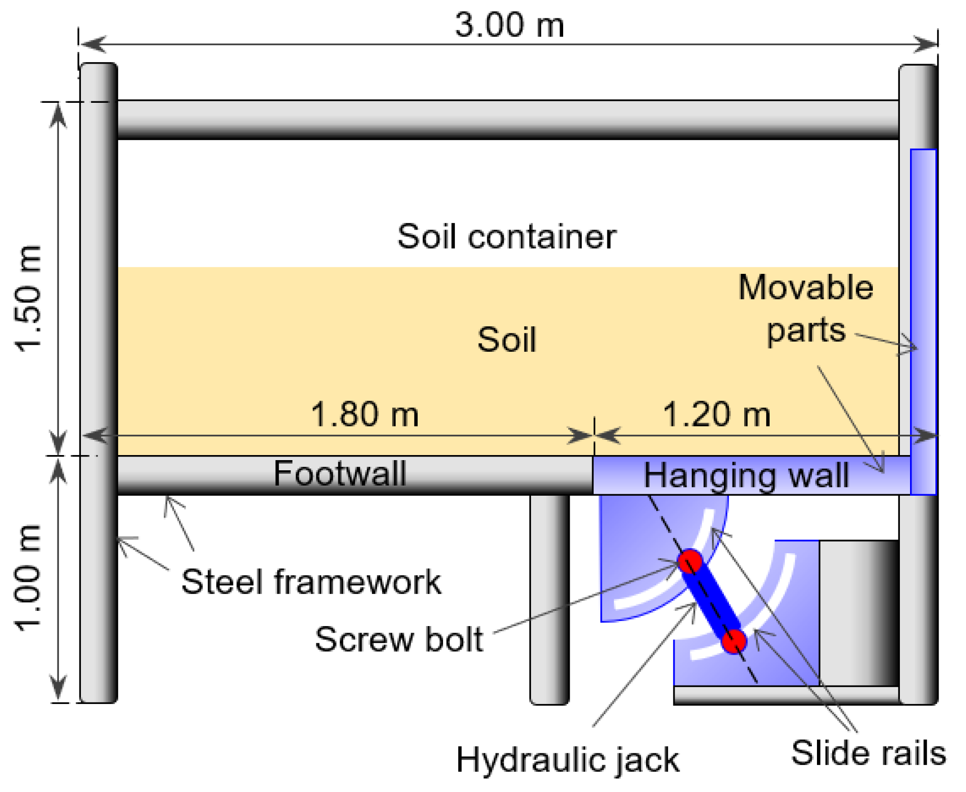
The tests in this study were performed through a fault simulator shown in Figure 2. It can simulate normal or reverse faulting under different fault dip angles. The dimensions of the soil container were 1.5 m (width) × 3.0 m (length) × 1.5 m (height). The front window of the soil container was transparent, where the fault ruptures could be observed by a digital camera. The detailed information of the apparatus is provided by Wang et al. (2022) [38].
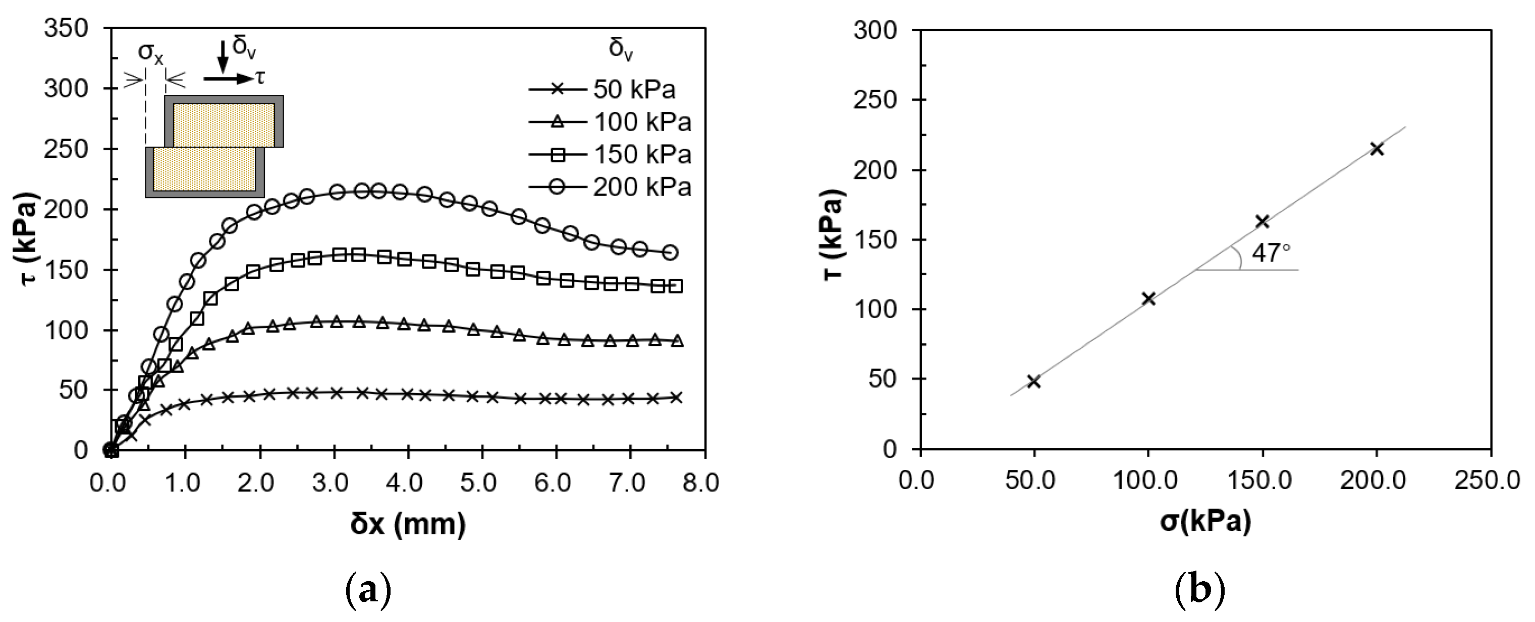
In this study, two cases were designed: TN (tunnel without a rigid bottom wall) and TB (tunnel with a rigid bottom wall). The test setups were the same for the two cases, as shown in Figure 3. In this section, all dimensions were reported in the model scale unless otherwise stated. The ground was modeled by quartz sand, with a height of H = 0.50 m and a width of W = 1.80 m. The sand had a relative density of Dr = 80% and a unit weight of γ = 15.50 kN/m3. Figure 4 shows the shear tests of the sand. According to the tests (Figure 4), the peak frictional angle φp and the critical one φres were 47° and 30°, respectively. The corrected area was used in the stress calculations following Ac = A0 (1 − δx/6), where A0 and Ac are the actual and modified shear box area, respectively, and δx is the horizontal displacement. Detailed frictional angle calculation is presented in Figure 4b. The dilation angle Ψp was 21°, which was calculated by Ψp = 0.8 (φp − φres) [39]. The designed bedrock offset was 57.735 mm along the dip angle of 60°. Its vertical component was h = 50 mm.
Circular model tunnels were applied in this study. The model tunnels are made of resin, with a thickness of t = 6 mm (Figure 3). The outer and inner diameters were D = 132 mm and d = 120 mm, respectively. The model bottom wall in Case TB was made of resin as well. It had a height of L = 40 mm and a thickness of tb = 6 mm. The friction angle between the soil and the model tunnel (or rigid bottom walls) was about 11° [40]. The detailed parameters and properties of tunnels are listed in Table 2. In this study, the similarity ratios of the geometric scale and Young’s modulus of tunnels were 25 and 14, respectively. The tunnels were buried with a depth of 132 mm, which equaled their outer diameters. The two ends of the tunnels were free.
During the tests, the fault rupture, vertical displacement of the tunnel, strain of the tunnel, and soil pressure below the tunnel were observed or measured (Figure 3). The in-flight photographs were captured during faulting to observe the fault ruptures. Seven LVDTs (linear variable displacement transducers) were installed at the ground surface to measure the vertical displacement of the tunnel. They were arranged more densely near the fault rupture and became sparser farther away from the fault plane. Calibrations of LVDTs were performed before tests. The movable core of the LVDT was pasted on the surface of the tunnel. The bending strain and axial strain at 10 designed cross-sections were measured by the strain gauges. At each cross-section, four strain gauges were pasted on the outer surface of the tunnel at its crown, bottom, left side, and right side, respectively. Six soil pressure sensors were set below the tunnel to record the change in soil pressure during faulting. The detailed locations of the above sensors are illustrated in Figure 3.
The ground was prepared by the air pluviation method. The colored sand was poured for every 50 mm height on the window side. During the process, the tunnel was fixed by jigs to ensure its designed location. The total fault deformation was h = 50 mm (2.5 m in the prototype scale). All data were recorded at every h = 2.5 mm increment.

4. Results and Discussions

4.1. Fault Rupture Propagation

Figure 5 shows the in-flight photographs in Cases TN and TB captured at h = 2.5 m. Hereafter, all data will be reported in the prototype scale unless otherwise specified. In Case TN, the first rupture R1 shows a curved path (Figure 5a). It outcrops at h = 0.5 m with a surface direction angle of 55°. According to previous studies [41,42,43,44], the rupture R1 is a logarithmic spiral. The surface direction angle in Case TN generally agrees with 45° + ψ/2 = 55.5°. The second rupture has a curved path and a straight path (Figure 5a). The result was consistent with the observations in centrifuge tests by [45]. They found that the lower path was a logarithmic spiral, while the upper path was a straight line. The direction of the straight part was controlled by the frictional angle. The direction angle should be 45° + φ/2 = 68.5° in this study, generally agreeing with the measured value of 66°. The fault rupture propagation in Case TB is similar to that in Case TN (Figure 5b), both for the rupture paths and the required h for outcropping. In the two cases, the tunnel axis cross ruptured R1 and R2 at approximately X = −5.5 m and 3.0 m, respectively.

4.2. Tunnel Behaviors

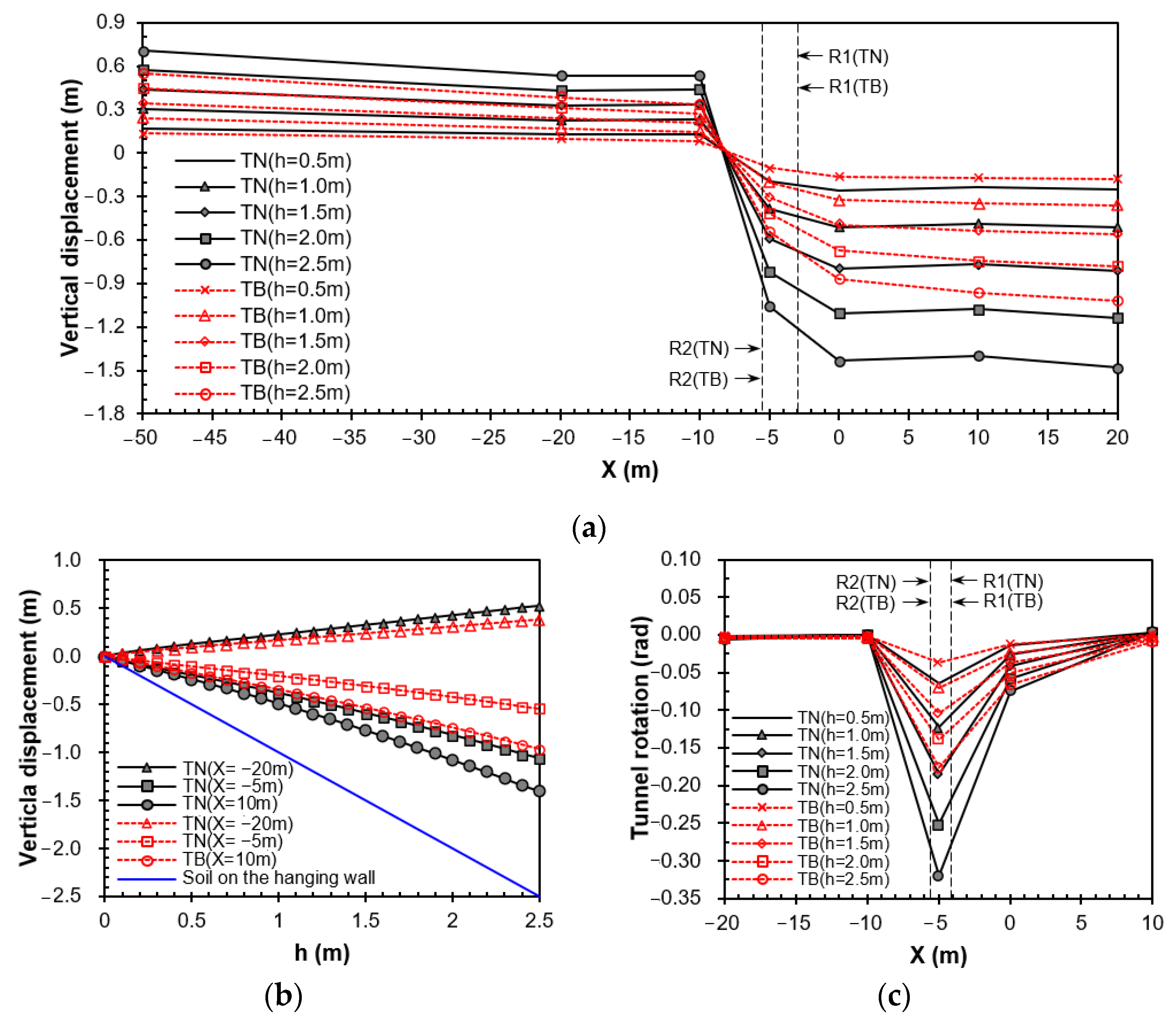
Figure 6 presents the vertical displacements and rotations of tunnels in Cases TN and TB. The tunnels deformed into an S shape in both cases (Figure 6a). The points at X = −20 m, −5 m, and −10 m in Figure 6b represent the points in the footwall, shear zone, and hanging wall, respectively. It shows that displacements at all points increased almost linearly with the fault deformation (Figure 6b). The results agree with the results of previous tests [38,46,47]. The tunnel in Case TB displaced smaller but had a longer deformed length than the tunnel in Case TN (Figure 6a). Cheng et al. (2025) [33] found that larger relative structure–soil stiffness led to longer deformed length. Therefore, the longer deformed length is owing to the larger tunnel stiffness with the rigid bottom wall. The smaller displacements and longer deformed length further led to smaller tunnel rotation in Case TB (Figure 6c). Figure 6c shows that the peak tunnel rotations in the two cases occur within the shear zone between the two ruptures. Tunnels on the footwall have positive values (Figure 6a), suggesting that the tunnels experienced slight overall tilting or rotation towards the hanging wall side. This was owing to the limited lengths of tunnels in the tests. The overall tilting or rotations of the tunnels were observed as well in previous tests [47,48].
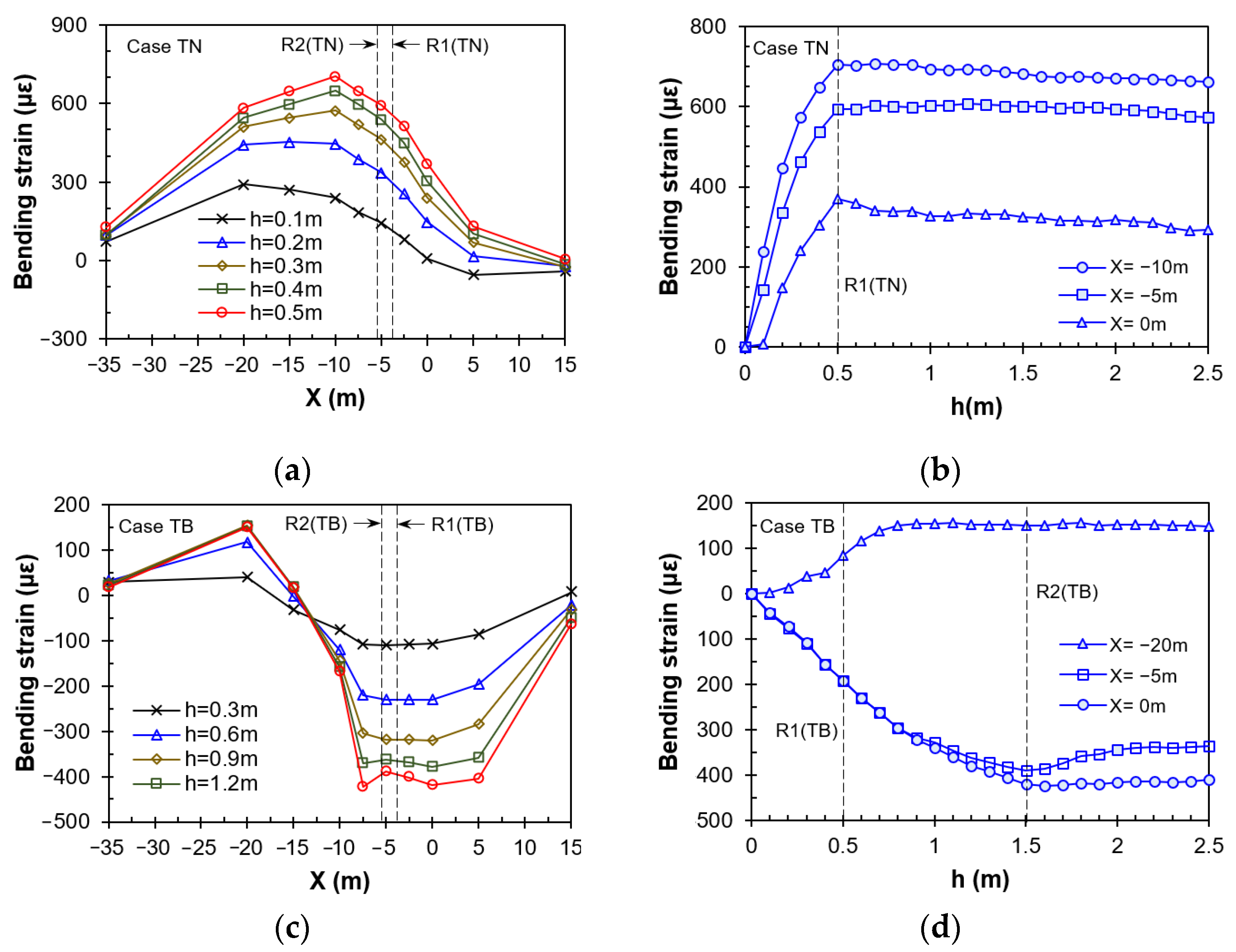
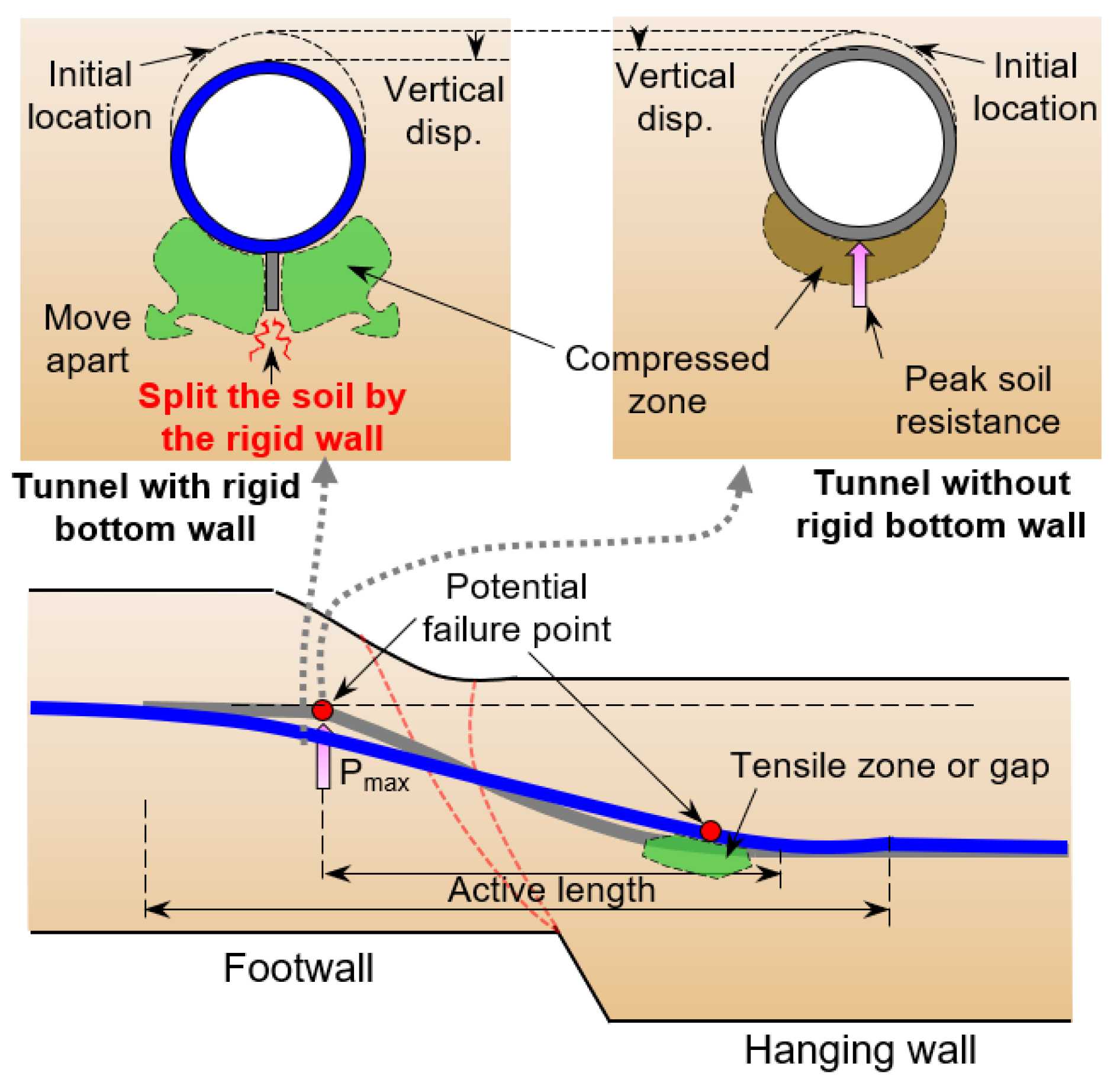
The measured bending strain of the tunnels in Cases TN and TB is presented in Figure 7. The measured earth pressures beneath the tunnels are displayed in Figure 8. In the study, the positive bending strain was defined when the tunnel crown experienced tensile strain. The positive and negative values represented the directions of the bending strain rather than the magnitude. In Case TN, the extreme positive bending strain was larger than the extreme negative one (Figure 7a). The values were 705.1 × 10⁻⁶ and −54.2 × 10⁻⁶ at h = 0.5 m, respectively. According to previous studies, the peak bending strain was induced at the footwall close to the rupture [49,50,51,52,53], where peak soil resistance occurred. The results of Case TN followed this rule. Its peak bending moment developed at X = −10 m (Figure 7a). The peak soil resistance was measured at X = −7.5 (Figure 8a). However, the measured extreme positive bending strain in Case TB was smaller than its extreme negative value (Figure 7b). At h = 0.5 m, the extreme values were 149.8 × 10⁻⁶ and −423.2 × 10⁻⁶, respectively. It indicates that the potential failure point of the tunnel, where peak bending strain occurs, was located at the hanging wall close to the rupture. The bending strain distribution agrees with the measured soil resistance presented in Figure 8b. The soil resistance reduced at X = −5 m and −2.5 m during faulting (Figure 8b). This suggests that a tension sand zone or a gap was induced below the bottom of the tunnel, which was caused by the great displacement difference between the tunnel and the soil [37,54]. Therefore, large negative bending strain occurred at X = −2.5 m to 5.0 m (Figure 7b), where the tunnel lost the support of the soil below the tunnel. The soil resistance at the footwall in Case TB was smaller than that in Case TN (Figure 7). It may have been because the sharp bottom wall split the soil to release the degree of soil compression and reduce the soil resistance.
Figure 7b,d show that the bending strains at the measured points increased initially. They become relatively stable after R1 or R2 outcropped (Figure 7b). According to the test by Yao et al. (2022) [52], the bending strain of the pipe mainly occurred within a narrow zone after outcropping, while the values at the other part of the pipe remained almost stable. Therefore, the true extreme bending strain may have been missed by the relatively large interval of the strain gauges in this study.
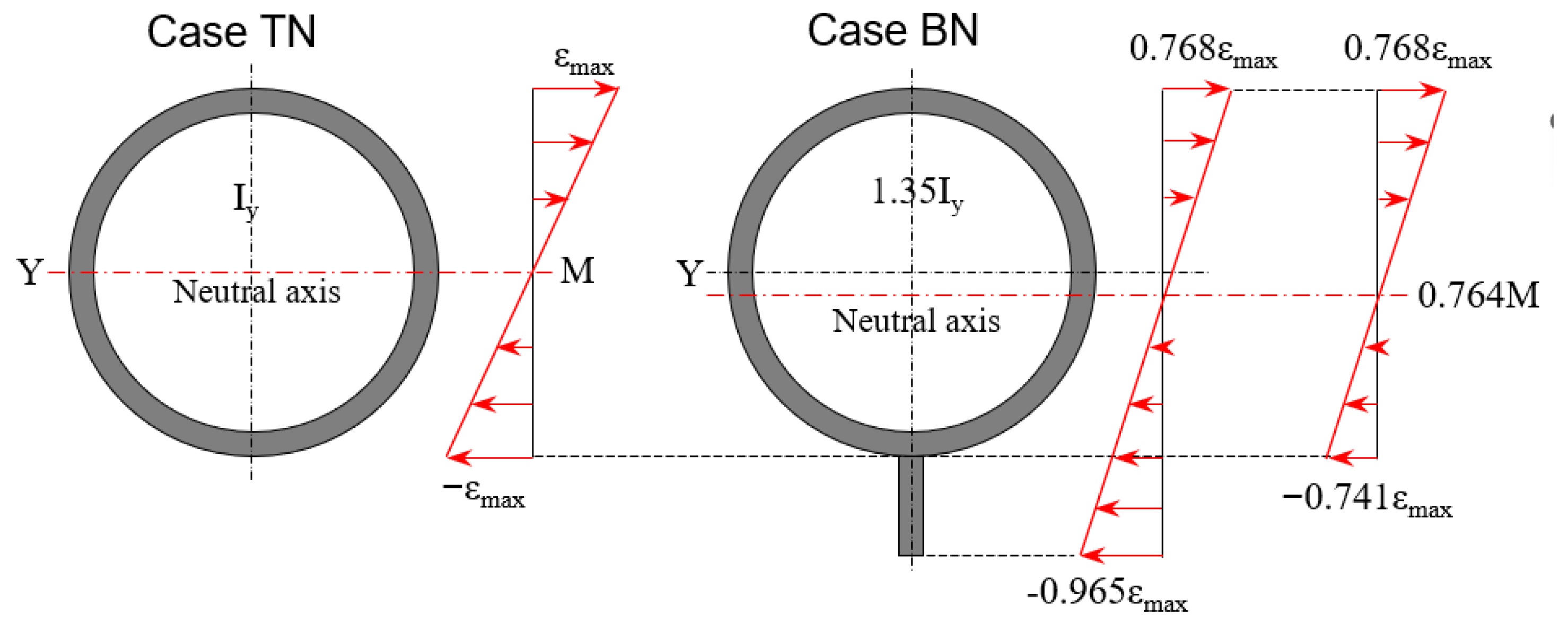
For the measured values, the peak bending strain in Case TB was smaller than that in Case TN (Figure 7a,c). It should be noted that the measured bending strain in Case TB was only the value on the circular tunnel, excluding the rigid bottom wall. As the measured extreme bending strain may have been missed, further comparisons of the bending strain in the two cases were based on the bending stiffnesses of the tunnel. The bending stiffness EI of the tunnel in Case TB was 1.35 times that of Case TN. This suggests that the tunnel with the rigid bottom wall would experience smaller bending strain under the same external loads. Figure 9 shows the bending strain at a cross-section under the same external loads in Cases TN and BN. In the figure, the Y, Iy, M, and εmax represent the coordinate, moment of inertia along the Y-coordinate, bending moment, and the maximum strain, respectively. As illustrated in Figure 9, the bending strains at the tunnel crown and invert in Case TB are 0.768 and 0.741 times those of Case TN under the same bending moment, respectively. In practice, the external loads of the tunnel in the two cases may be different. However, the tunnel rotation shown in Figure 6c also indicates that smaller bending strains occurred in Case TB.
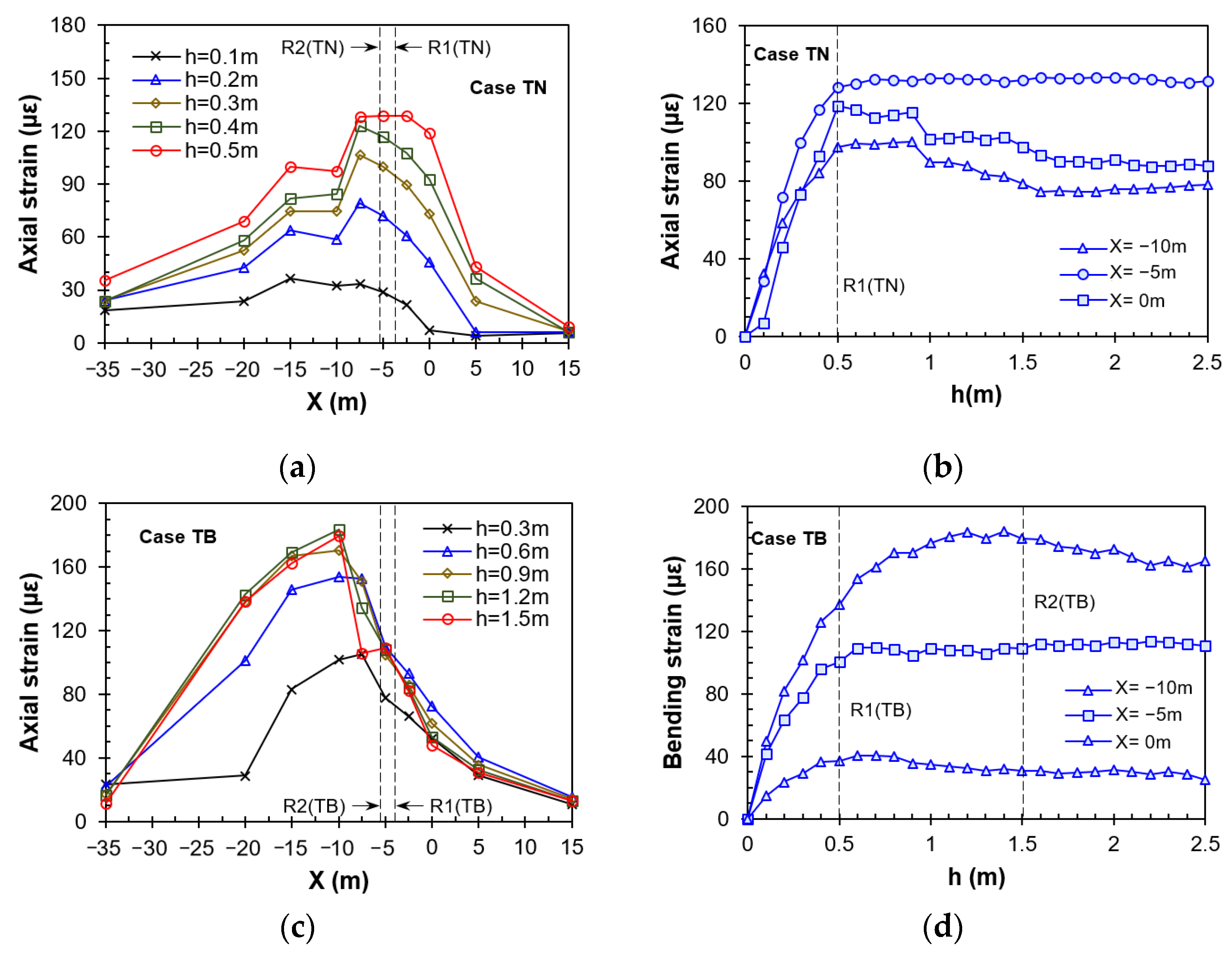
The measured extreme positive bending strain occurred at X = −20 m in Case TB (Figure 7c). The location of the extreme positive value moved towards the footwall side, compared with that of Case TN. It may have been a result of the longer deformed length in Case TB. The measured axial strains are shown in Figure 10. Figure 10 shows that the longer deformed length may not be the only reason. In a normal fault, the part of the tunnel on the hanging wall is dragged by the soil, while its footwall side is constrained by the soil. Therefore, the peak axial strain of the tunnel should be induced at the fault rupture. The peak axial strain in Case TN followed this rule, where it occurred at X = −5 m (Figure 10a) between R1 and R2. However, the peak value developed at X = −10 m in Case TB (Figure 10b). This suggests that the true cross point between the fault plane and the tunnel was in the vicinity of X = −10 m. The tunnel–fault cross point moved to the footwall side, compared with the R1 and R2 observed at the front window. Therefore, the change in the tunnel–fault cross point may be another reason for the shifting of the location of the extreme positive bending strain. Figure 10c,d show that the axial strains become stable or slightly decrease after R1 or R2 outcrops. This suggests relative sliding occurred after outcropping, inducing sliding friction on the tunnel.

4.3. Possible Mechanisms

The above results show that the rigid bottom wall leads to a longer deformed length of the tunnel, smaller tunnel rotation, and smaller bending strain of the tunnel. This suggests that the rigid bottom wall was effective in mitigating tunnel damage in normal faults. The possible interaction mechanisms of the tunnel with and without a rigid bottom wall and normal faulting are illustrated in Figure 11. The rigid bottom wall leads to the larger stiffness of the tunnel. The larger stiffness further results in a longer deformed length of the tunnel, as Cheng et al. (2025) [33] found that larger relative structure–soil stiffness leads to longer deformed length. With a longer deformed length to accommodate the fault deformation, the tunnel was in a safer state, experiencing smaller rotation and bending strain. In addition, the potential failure point, where peak bending strain occurred, moved from the footwall to the hanging wall. For the tunnel without the bottom wall, the failure point was likely induced at the footwall close to the rupture, where peak soil resistance developed due to highly compressed soil [51,52,55,56]. For the tunnel with the rigid bottom wall, the peak bending strain appeared at the hanging wall close to the rupture. It was because a tensile soil zone or a gap existed below the tunnel invert in this area, which was caused by the great displacement difference between the tunnel and the soil. On the footwall close to the rupture, the sharp bottom wall may split the soil to reduce the soil resistance. It should be noted that the novel rigid bottom wall was proposed for shallow tunnels in overlying soil. It cannot be applied in a hard bedrock layer due to the small tunnel–rock relative stiffness.

5. Conclusions

In this study, a novel rigid bottom wall was proposed to protect shallow tunnels subjected to normal faulting. The rigid wall was made of reinforced concrete, installed below the inverted arch. Two physical tests were performed to compare the behaviors of the tunnel with and without the rigid bottom wall. The fault rupture propagation, tunnel displacement, bending strain of the tunnel, axial strain of the tunnel, and soil resistance were measured during the tests.
The results show that the rigid bottom wall was effective in mitigating tunnel damage in normal faults. The rigid bottom wall led to a longer deformed length of the tunnel by increasing the tunnel stiffness. With a longer deformed length to accommodate the fault deformation, the tunnel experienced smaller rotation and bending strain. The maximum rotation and the maximum bending strain decreased 45% and 40%, respectively. In addition, the rigid bottom wall seemed to change the locations of the potential failure point and tunnel–fault cross point. The potential failure point moved from the footwall to the hanging wall, while the tunnel–fault cross point shifted towards the footwall. Due to the limited number of tests in this study, further physical and numerical modeling is suggested for future studies.

Author Contributions

Methodology, C.Y.; software, Y.L.; formal analysis, Y.L., Y.Z. and D.G.; investigation, S.L. and D.G.; data curation, Y.Z. and S.L.; writing—original draft preparation, C.Y.; writing—review and editing, W.Y.; supervision, W.Y.; funding acquisition, C.Y. All authors have read and agreed to the published version of the manuscript.

Funding

The authors would like to acknowledge the financial support from the National Natural Science Foundation of China, grant number 52478417.

Data Availability Statement

Data is contained within the article. The original contributions presented in this study are included in the article. Further inquiries can be directed to the corresponding author.

Conflicts of Interest

Author Deping Guo was employed by the company Sichuan Shudao Railway Investment Group Co., Ltd. The remaining authors declare that the research was conducted in the absence of any commercial or financial relationships that could be construed as a potential conflict of interest.

References

  1. Wang, W.L.; Wang, T.T.; Su, J.J.; Lin, C.H.; Seng, C.R.; Huang, T.H. Assessment of Damage in Mountain Tunnels Due to the Taiwan Chi-Chi Earthquake. Tunn. Undergr. Space Technol. 2001, 16, 133–150. [Google Scholar] [CrossRef]
  2. Anastasopoulos, I.; Gazetas, G. Analysis of Cut-and-Cover Tunnels against Large Tectonic Deformation. Bull. Earthq. Eng. 2010, 8, 283–307. [Google Scholar] [CrossRef]
  3. Yao, C.; Duan, J.; Liu, Y.; He, C.; Liu, Y.; Yang, W.; Yan, Q.; Luo, W. Tunnels Crossing Active Faults: A Review of Case Histories and Modeling Methods. Tunn. Undergr. Space Technol. 2026, 168, 107086. [Google Scholar] [CrossRef]
  4. Huang, S.; Xin, C.; Song, D.; Feng, W.; Liu, X.; Wang, E.; Xu, T.; Xiong, X. Resilience Assessment of the Seismic Damage Mechanism of the Daliang High-Speed Railway Tunnel in the 2022 Menyuan Earthquake (Mw 6.7) in China. Transp. Geotech. 2024, 49, 101417. [Google Scholar] [CrossRef]
  5. Chen, P.; Geng, P.; Chen, J.; Gu, W. The Seismic Damage Mechanism of Daliang Tunnel by Fault Dislocation during the 2022 Menyuan Ms6.9 Earthquake Based on Unidirectional Velocity Pulse Input. Eng. Fail. Anal. 2023, 145, 107047. [Google Scholar] [CrossRef]
  6. Tao, L.; Wang, Z.; Shi, C.; Zhang, H. Investigation of the Longitudinal Mechanical Response of Pipeline or Tunnel under Reverse Fault Dislocation. Rock Mech. Rock Eng. 2023, 56, 6237–6259. [Google Scholar] [CrossRef]
  7. Zhang, X.; Yu, L.; Wang, M.; Yang, H. Mechanical Response and Failure Characteristics of Tunnels Subjected to Reverse Faulting with Nonuniform Displacement: Theoretical and Numerical Investigation. Eng. Fail. Anal. 2024, 156, 107809. [Google Scholar] [CrossRef]
  8. Zhang, S.; Li, Z.; Bu, R.; Shen, M. Nonlinear Structural Responses of the Buried Oval Steel Pipelines Crossing Strike-Slip Faults. Structures 2024, 69, 107366. [Google Scholar] [CrossRef]
  9. Gao, J.; Wang, Q.; Wang, R.; Yang, J.; Yang, Y. Model Test Study on the Deformation and Failure Characteristics of Mountain Tunnel under a Strike-Slip Fault Dislocation. Structures 2024, 60, 105903. [Google Scholar] [CrossRef]
  10. Schaumann, M.; Gamba, D.; Garcia Morales, H.; Corsini, R.; Guinchard, M.; Scislo, L.; Wenninger, J. The Effect of Ground Motion on the LHC and HL-LHC Beam Orbit. Nucl. Instrum. Methods Phys. Res. A 2023, 1055, 168495. [Google Scholar] [CrossRef]
  11. Ji, Y.; Chen, Y.; Hofmann, H.; Zhang, Y.; Zang, A.; Zimmermann, G. The Role of Temperature-enhanced Fault Closure in Promoting Postinjection Pressure Diffusion and Seismicity in Enhanced Geothermal Systems. Deep. Undergr. Sci. Eng. 2023, 2, 394–405. [Google Scholar] [CrossRef]
  12. Han, X.; Li, W. Numerical Analysis on the Structure Type and Mechanical Response of Tunnel Crossing Active Reverse Fault. Geofluids 2021, 5513042. [Google Scholar] [CrossRef]
  13. Zaheri, M.; Ranjbarnia, M.; Dias, D.; Oreste, P. Performance of Segmental and Shotcrete Linings in Shallow Tunnels Crossing a Transverse Strike-Slip Faulting. Transp. Geotech. 2020, 23, 100333. [Google Scholar] [CrossRef]
  14. Shen, Y.S.; Wang, Z.Z.; Yu, J.; Zhang, X.; Gao, B. Shaking Table Test on Flexible Joints of Mountain Tunnels Passing through Normal Fault. Tunn. Undergr. Space Technol. 2020, 98, 103299. [Google Scholar] [CrossRef]
  15. Shi, X.; Feng, X.; Shi, T. Novel Corrugated Tube–Rubber–Concrete Flexible Joint for Lining Water Conveyance Tunnels Crossing Reverse Faults: Numerical Analysis of Dislocation Resistance Performance. Tunn. Undergr. Space Technol. 2024, 144, 105556. [Google Scholar] [CrossRef]
  16. Zhang, J.; Cui, Z.; Sheng, Q.; Zhao, W.; Song, L. Experimental Study on the Effect of Flexible Joints of a Deep-Buried Tunnel across an Active Fault under High in-Situ Stress Conditions. Undergr. Space 2024, 19, 189–207. [Google Scholar] [CrossRef]
  17. Baziar, M.H.; Nabizadeh, A.; Jung Lee, C.; Yi Hung, W. Centrifuge Modeling of Interaction between Reverse Faulting and Tunnel. Soil Dyn. Earthq. Eng. 2014, 65, 151–164. [Google Scholar] [CrossRef]
  18. Nabizadeh, A.; Mojtahedi, A.S. Centrifuge Modeling of Normal Faulting and Underground Tunnel in Sandy Soil Deposit. Soils Rocks 2021, 44, e2021059520. [Google Scholar] [CrossRef]
  19. Cividini, A.; Gioda, G.; Petrini, V. Finite Element Evaluation of the Effects of Faulting on a Shallow Tunnel in Alluvial Soil. Acta Geotech. 2010, 5, 113–120. [Google Scholar] [CrossRef]
  20. Aghamolaei, M.; Saeedi Azizkandi, A.; Khorashadizadeh, M. Evaluation of the Mechanical Response of Tunnel Lining Induced by Reverse Faulting Using Numerical Simulations. Int. J. Civil. Eng. 2023, 21, 1739–1750. [Google Scholar] [CrossRef]
  21. Wu, X.; Nie, C.; Li, D.; Qiu, F.; Tang, Y. Structural Response of a Prefabricated Utility Tunnel Subject to a Reverse Fault. Buildings 2022, 12, 1086. [Google Scholar] [CrossRef]
  22. Mehrabi, R.; Baziar, M.H.; Nabizadeh, A.; Hung, W.Y. Discrete-Element Modelling of Underground Tunnel Response to Reverse Fault Rupture in Sand. Proc. Inst. Civil. Eng.–Geotech. Eng. 2021, 176, 356–368. [Google Scholar] [CrossRef]
  23. Ghadimi Chermahini, A.; Tahghighi, H. Numerical Finite Element Analysis of Underground Tunnel Crossing an Active Reverse Fault: A Case Study on the Sabzkouh Segmental Tunnel. Geomech. Geoengin. 2019, 14, 155–166. [Google Scholar] [CrossRef]
  24. Baziar, M.H.; Nabizadeh, A.; Mehrabi, R.; Lee, C.J.; Hung, W.Y. Evaluation of Underground Tunnel Response to Reverse Fault Rupture Using Numerical Approach. Soil Dyn. Earthq. Eng. 2016, 83, 1–17. [Google Scholar] [CrossRef]
  25. Yao, C.; Yan, Q.; Sun, M.; Zhang, J.; He, C. Analysis of a Novel Subway Station Structure to Mitigate Damages Induced by Normal Faulting. Soil Dyn. Earthq. Eng. 2020, 136, 106246. [Google Scholar] [CrossRef]
  26. Yao, C.; Yan, Q.; Sun, M.; Dong, W.; Guo, D. Rigid Diaphragm Wall with a Relief Shelf to Mitigate the Deformations of Soil and Shallow Foundations Subjected to Normal Faulting. Soil Dyn. Earthq. Eng. 2020, 137, 106264. [Google Scholar] [CrossRef]
  27. Yao, C.; Luo, W.; Zhang, Y.; He, C.; Li, Y.; Yang, W.; Liu, Y.; Yuan, R. Inclined Rigid Sliding Walls to Protect Tunnels Subjected to Reverse Faulting. Comput. Geotech. 2023, 164, 105824. [Google Scholar] [CrossRef]
  28. Yao, C.; Luo, W.; Zhang, Y.; He, C.; Yang, W.; Zhang, J.; Yan, Q. A Novel Structural System to Protect Pipe-Jacking Tunnel Subjected to Normal Faulting: Physical Modeling. Tunn. Undergr. Space Technol. 2025, 157, 106349. [Google Scholar] [CrossRef]
  29. Yao, C.; Zhang, Y.; He, C.; Kang, X.; Yang, W.; Geng, P.; Wang, T. An Anti-Rotation Shelf to Mitigate the Rotation of Shield Tunnels Subjected to Normal Faulting. Comput. Geotech. 2023, 156, 105297. [Google Scholar] [CrossRef]
  30. Zhang, X.; Wang, M.; Li, Z.; Yu, L.; Yang, H. Mechanical Response of Tunnels Crossing Active Fault Zones under Normal or Reverse Faulting: A Refined Nonlinear Analytical Approximate Solution. Comput. Geotech. 2024, 167, 106028. [Google Scholar] [CrossRef]
  31. Wang, Z.; Zhong, Z.; Zhao, M.; Du, X.; Huang, J.; Wang, H. Experimental Study on Mechanical Behavior and Countermeasures of Mountain Tunnels under Strike-Slip Fault Movement. Undergr. Space 2025, 21, 1–21. [Google Scholar] [CrossRef]
  32. Ba, Z.; Wang, Y.; Li, D. Numerical Investigation on Seismic Damage of Tunnels Subjected to Fault Dislocation Using the FDM-DEM Approach. Comput. Geotech. 2025, 182, 107169. [Google Scholar] [CrossRef]
  33. Cheng, T.; Yao, C.; Duan, J.; He, C.; Xu, H.; Yang, W.; Yan, Q. Prediction of Active Length of Pipes and Tunnels under Normal Faulting with XGBoost Integrating a Complexity-Performance Balanced Optimization Approach. Comput. Geotech. 2025, 179, 107048. [Google Scholar] [CrossRef]
  34. Melissianos, V.E.; Lignos, X.A.; Bachas, K.K.; Gantes, C.J. Experimental Investigation of Pipes with Flexible Joints under Fault Rupture. J. Constr. Steel Res. 2017, 128, 633–648. [Google Scholar] [CrossRef]
  35. Kaya, E.S.; Uckan, E.; Taciroglu, E. Damage Mitigation of Fault-Crossing Elbowed Water Transmission Pipes Using Flexible Joints. Soil Dyn. Earthq. Eng. 2026, 200, 109845. [Google Scholar] [CrossRef]
  36. Rojhani, M.; Moradi, M.; Derakhshani, A. Innovative Mitigation Method for Buried Pipelines Crossing Faults. Earthq. Eng. Eng. Vib. 2022, 21, 1089–1101. [Google Scholar] [CrossRef]
  37. Rasouli, H.; Fatahi, B. Geofoam Blocks to Protect Buried Pipelines Subjected to Strike-Slip Fault Rupture. Geotext. Geomembr. 2020, 48, 257–274. [Google Scholar] [CrossRef]
  38. Wang, T.; Geng, P.; Li, P.; Wang, Q.; Wang, L. Deformation and Failure of Overburden Soil Subjected to Normal Fault Dislocation and Its Impact on Tunnel. Eng. Fail. Anal. 2022, 142, 106747. [Google Scholar] [CrossRef]
  39. Bolton, M.D. The Strength and Dilatancy of Sands. Géotechnique 1986, 36, 65–78. [Google Scholar] [CrossRef]
  40. Jardine, R.J.; Potts, D.M.; Fourie, A.B.; Burland, J.B. Studies of the Influence of Non-Linear Stress–Strain Characteristics in Soil–Structure Interaction. Géotechnique 1986, 36, 377–396. [Google Scholar] [CrossRef]
  41. Cole, D.A.; Lade, P.V. Influence Zones in Alluvium Over Dip-Slip Faults. J. Geotech. Eng. 1984, 110, 599–615. [Google Scholar] [CrossRef]
  42. Lade, P.V.; Cole, D.A.; Cummings, D. Multiple Failure Surfaces Over Dip-Slip Faults. J. Geotech. Eng. 1984, 110, 616–627. [Google Scholar] [CrossRef]
  43. Stone, K.J.L.; Wood, D.M. Effects of Dilatancy and Particle Size Observed in Model Tests on Sand. Soils Found. 1992, 32, 43–57. [Google Scholar] [CrossRef]
  44. Yao, C.; Takemura, J.; Ma, G.; Dai, C.; An, Z. Effect of Boundary Friction on Revere Fault Rupture Propagation in Centrifuge Tests. Soil Dyn. Earthq. Eng. 2021, 147, 106811. [Google Scholar] [CrossRef]
  45. Yao, C.; Takemura, J.; Zhang, J. Centrifuge Modeling of Single Pile-Shallow Foundation Interaction in Reverse Fault. Soil Dyn. Earthq. Eng. 2021, 141, 106538. [Google Scholar] [CrossRef]
  46. Kiani, M.; Akhlaghi, T.; Ghalandarzadeh, A. Experimental Modeling of Segmental Shallow Tunnels in Alluvial Affected by Normal Faults. Tunn. Undergr. Space Technol. 2016, 51, 108–119. [Google Scholar] [CrossRef]
  47. Cai, Q.P.; Peng, J.M.; Ng, C.W.W.; Shi, J.W.; Chen, X.X. Centrifuge and Numerical Modelling of Tunnel Intersected by Normal Fault Rupture in Sand. Comput. Geotech. 2019, 111, 137–146. [Google Scholar] [CrossRef]
  48. Rostami, H.; Osouli, A.; Kumar, S. Experimental Modeling of Far-Field Effects in Buried Pipelines Subjected to Reverse Faulting. Soil Dyn. Earthq. Eng. 2023, 164, 107561. [Google Scholar] [CrossRef]
  49. Ha, D.; Abdoun, T.H.; O’Rourke, M.J.; Symans, M.D.; O’Rourke, T.D.; Palmer, M.C.; Stewart, H.E. Buried High-Density Polyethylene Pipelines Subjected to Normal and Strike-Slip Faulting—A Centrifuge Investigation. Can. Geotech. J. 2008, 45, 1733–1742. [Google Scholar] [CrossRef]
  50. Moradi, M.; Rojhani, M.; Galandarzadeh, A.; Takada, S. Centrifuge Modeling of Buried Continuous Pipelines Subjected to Normal Faulting. Earthq. Eng. Eng. Vib. 2013, 12, 155–164. [Google Scholar] [CrossRef]
  51. Saiyar, M.; Ni, P.; Take, W.A.; Moore, I.D. Response of Pipelines of Differing Flexural Stiffness to Normal Faulting. Géotechnique 2016, 66, 275–286. [Google Scholar] [CrossRef]
  52. Yao, C.; He, C.; Huang, X.; Takemura, J.; Yang, W.; An, Z. Response of a Continuous Pipeline in Sand Subjected to Normal Faulting. Transp. Geotech. 2022, 36, 100824. [Google Scholar] [CrossRef]
  53. Li, H.; Li, X.; Liu, H. Deformation and Failure Mechanism of Metro Shield Tunnel Subjected to Buried Fault Dislocation. Eng. Fail. Anal. 2023, 153, 107551. [Google Scholar] [CrossRef]
  54. Zhang, Z.; Zhang, Y.; Wei, R.; Yin, C.; Zhang, H. The Damage Mode and Forced Response Characteristics of Articulated Lining Structure: A Case Study of Metro Tunnel under a Reverse Fault Action. Tunn. Undergr. Space Technol. 2023, 140, 105246. [Google Scholar] [CrossRef]
  55. Tsatsis, A.; Loli, M.; Gazetas, G. Pipeline in Dense Sand Subjected to Tectonic Deformation from Normal or Reverse Faulting. Soil Dyn. Earthq. Eng. 2019, 127, 105780. [Google Scholar] [CrossRef]
  56. Sabagh, M.; Ghalandarzadeh, A. Centrifugal Modeling of Continuous Shallow Tunnels at Active Normal Faults Intersection. Transp. Geotech. 2020, 22, 100325. [Google Scholar] [CrossRef]
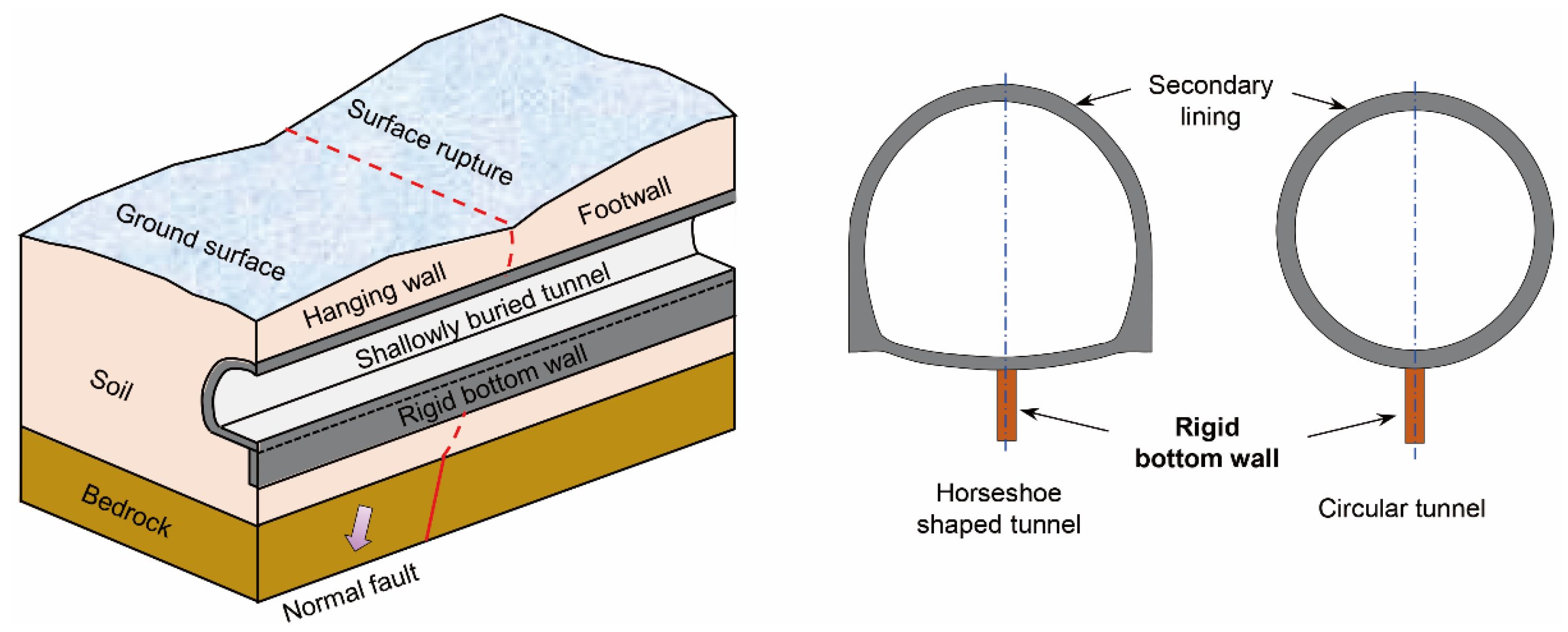
Figure 1. Schematic of the rigid bottom wall.
Buildings 15 04156 g001
Figure 2. Schematic of the fault simulator [28].
Buildings 15 04156 g002
Figure 3. Test setup (in the model scale).
Buildings 15 04156 g003
Figure 4. Direct shear tests of the sand: (a) test results; (b) frictional angle calculation.
Buildings 15 04156 g004
Figure 5. In-flight photographs at h = 2.5 m: (a) Case TN; (b) Case TB.
Buildings 15 04156 g005
Figure 6. Vertical displacements and rotations of tunnels in Cases TN and TB: (a) vertical displacements along the tunnel; (b) vertical displacements at X = −20 m, −5 m, and −10 m; (c) tunnel rotation along the tunnel.
Buildings 15 04156 g006
Figure 7. Bending strain of the tunnels in Cases TN and TB: (a) bending strain distribution along the tunnel in Case TN; (b) bending strain versus fault deformation in Case TN; (c) bending strain distribution along the tunnel in Case TB; (d) bending strain versus fault deformation in Case TB.
Buildings 15 04156 g007
Figure 8. Measured earth pressures beneath the tunnels: (a) in Case TN; (b) in Case TB.
Buildings 15 04156 g008
Figure 9. Illustration of bending strain at a cross-section under the same external loads in Cases TN and BN.
Buildings 15 04156 g009
Figure 10. Axial strain of the tunnels in Cases TN and TB: (a) axial strain distribution along the tunnel in Case TN; (b) axial strain versus fault deformation in Case TN; (c) axial strain distribution along the tunnel in Case TB; (d) axial strain versus fault deformation in Case TB.
Buildings 15 04156 g010
Figure 11. Possible interaction mechanisms of the tunnel with a rigid bottom wall and normal faulting.
Buildings 15 04156 g011
Table 1. Anti-fault measurements for tunnels and pipes in overlying soils.
ConditionsMeasuresStructuresReferences
Structures paralleling the fault planesDiaphragm wallSubway station[25,26]
Inclined sliding wallTunnel[27]
Anti-rotation shelfTunnel[28,29]
Structures crossing faultsflexible jointsTunnel or pipe[34,35]
low-density gravel with high porosityPipe[36]
geofoam blocksPipe[37]
pumice with high porosityPipe[36]
Table 2. Parameters and properties of tunnels.
ScaleOuter Diameter, DInner Diameter, dThickness, tHeight of Wall, LThickness of the Wall, tbUnit Weight, γYoung’s Modulus, EYielding Stress, σy
Model132 mm120 mm6 mm40 mm6 mm1.2 kN/m32.46 GPa50 MPa
Prototype3.30 m3.00 m0.15 m1.00 m0.15 m25 kN/m334.5 GPa59 MPa
Disclaimer/Publisher’s Note: The statements, opinions and data contained in all publications are solely those of the individual author(s) and contributor(s) and not of MDPI and/or the editor(s). MDPI and/or the editor(s) disclaim responsibility for any injury to people or property resulting from any ideas, methods, instructions or products referred to in the content.