Article

Bending Characteristics of Hybrid Fiber Concrete Beams Reinforced with Steel–GFRP Hybrid Rebars

Chair of Research and Studies in Strengthening and Rehabilitation of Structures, Department of Civil Engineering, College of Engineering, King Saud University, P.O. Box 800, Riyadh 11421, Saudi Arabia
*
Author to whom correspondence should be addressed.
Buildings 2025, 15(22), 4146; https://doi.org/10.3390/buildings15224146 (registering DOI)
Submission received: 10 October 2025 / Revised: 2 November 2025 / Accepted: 10 November 2025 / Published: 17 November 2025
(This article belongs to the Section Building Structures)

Abstract

The current study aims to investigate the effect of using hybrid bars on the bending characteristics of hybrid fiber-reinforced concrete (FRC) beams. For this purpose, a series of flexural tests on FRC beams were conducted. Four FRC beams were fabricated, each with a section of 120 mm × 185 mm and an overall length of 1.5 m. The FRC beams’ tension reinforcement consisted of a hybrid configuration of steel and glass fiber-reinforced polymer (GFRP) rebars. The concrete mix included a hybrid fiber content of 1% by volume, with 0.75% for hooked-end steel fibers (SF) and 0.25% polypropylene fibers (PP). The simply supported FRC beams were tested under the action of two-point loads. The results demonstrated that the inclusion of hybrid fibers substantially improved the crack widening and propagation in FRC beams compared to normal concrete (NC) beams. The maximum load capabilities of the FRC beams surpassed those of the NC beams up to 13.2%. The GFRP bars further enhanced the beams’ load-carrying capacity with an observed increase of up to 42.5%, when compared to the steel-reinforced FRC beam (BFRC-3S). Additionally, hybrid reinforcement improved ductility, with increases of 39.1% and 167.1% when one or two GFRP bars were replaced by steel, respectively.

1. Introduction

The accelerated corrosion of steel rebars in reinforced-concrete (RC) structural elements is a primary factor limiting their service life. Exposure to moisture, deicing salts, and chlorides makes elements such as bridges, dams, and tanks particularly vulnerable to the corrosion of steel bars. To fulfill the durability and limit state requirements for these constructions, either quality of concrete is improved [1] or conventional steel rebars are substituted or coated with protective layers [2]. For the past few decades, fiber-reinforced polymer (FRP) rebars have been extensively utilized as a substitute for steel bars to address the corrosion issues associated with steel rebars. The prevalent varieties of fibers used for making FRP bars include glass, carbon, basalt, and aramid. FRP rebars offer high tensile strength and exceptional resistance to corrosion. Several studies have examined the characteristics of RC beams having FRP bars [3,4,5,6,7,8] but there is a need to improve their performance.
Unlike steel, FRP rebars display an almost linear stress–strain response under tension until failure, characterized by a low elastic modulus and the absence of ductility. This results in a wider crack width, larger deformations, and sudden brittle failure modes [9,10,11]. Experimental test findings indicated that the observed failure modes were primarily compression failures [12,13,14]. These results indicate that FRP bars are not appropriate for moment–resisting RC frames. To address these shortcomings, researchers have suggested combining FRP bars with steel bars (hybrid rebars) for reinforcing beams to improve corrosion resistance as well as flexural capacity and ductility [15,16,17]. In such systems, FRP rebars are positioned at the corners of the member cross-section, while steel rebars are situated within the element to enhance protection. This configuration improves corrosion resistance while retaining the ductility provided by steel bars. Consequently, utilizing an appropriate amount of reinforcement for hybrid rebars will ensure that the beam section fails through the steel rebars’ yielding, thereby facilitating a ductile failure and avoiding brittle failure. The presence of FRP bars simultaneously enhances the load-bearing capability of the RC structures [18,19,20].
Aiello et al. [21] found that incorporating steel reinforcement bars with aramid FRP (AFRP) bars into RC beams enhanced overall performance by increasing beam stiffness and decreasing deflections. Similarly, Yoon et al. [22] showed that the incorporation of hybrid bars (steel and FRP) mitigates the drawbacks typically associated with FRP-reinforced beam, such as low stiffness, wide cracks, excessive deflection, and inadequate ductility. Moreover, another study [15] demonstrated that the bending strength of concrete beams having hybrid rebars improves with the enhancement in the effective rebar ratio. It is reported that the spacing of cracks, deflection, and ductility index of concrete beams having hybrid rebars were between those of steel-RC and basalt FRP (BFRP) RC beams [17]. Thamrin et al. [23] demonstrated that the reinforcement ratio of FRP to steel bars ( A f / A s ) substantially influences the flexural performance of hybrid-RC beams. As this ratio increases, the flexural strength gradually rises, while the ductility decreases. Pang et al. [24] also reported that the A f / A s ratio substantially influences the hybrid-RC beams’ ductility, necessitating careful control of this ratio to ensure compliance with ductility standards for hybrid-RC beams. Yang et al. [25] suggested a design approach for these beams that involved section optimization. They showed that the flexural strength requirements can be met by hybrid-RC beams that have been designed with a lower A f / A s , while also maintaining higher ductility. Yang et al. [26] indicated that the novel hybrid (steel fiber-reinforced polymer composite bars and BFRP) beams exhibited superior ductility and service performance in comparison to conventional hybrid (glass FRP (GFRP) and steel) beams. These findings have been corroborated by numerous studies [27,28,29,30].
Numerous studies conducted on fiber-reinforced concrete (FRC) form a key component of the hybrid FRC beams developed in this study. Prior studies investigated the fiber’s performance with varying properties of concrete mixes, employing varied fiber ratios, sizes, types, and configurations [31,32,33,34,35]. However, this study uniquely combines several of the aforementioned aspects, distinguishing it from the existing literature. While the literature contains studies examining the influence of hybrid bars as well as fiber types on RC beam performance, there is limited research that has investigated the combined influence of hybrid fibers, specifically hooked-end steel fibers (SF) and polypropylene fibers (PP), with hybrid reinforcement bars composed of steel and GFRP. In the current study, the first author’s previous work [9] is further extended to investigate the effect of hybrid fibers and hybrid bars on the bending characteristics of FRC beams. For this purpose, a new series of flexural tests was conducted, involving four FRC beams of 120 mm × 185 mm and an overall length of 1.5 m. The tension rebars consisted of a hybrid configuration of steel and GFRP bars, while the concrete matrix was reinforced with 1% hybrid fibers by volume (0.75% SF and 0.25% PP fibers). The main contribution of this study lies in demonstrating the synergistic enhancement achieved by simultaneously employing hybrid fibers and hybrid reinforcement bars, offering a design pathway for improving flexural performance and crack resistance in FRC beams. Following the description of the experimental program in Section 2, the subsequent section presents a comprehensive discussion of the results, including the observed failure patterns, load–deflection behavior, load–strain response of the reinforcement bars, ultimate bending moment capacity, and the corresponding moment–curvature relationships.

2. Experimental Procedure

2.1. Concrete and Mixtures

The fiber-reinforced concrete (FRC) mix was prepared with the aim of attaining a cylindrical compressive strength ( f c ) of 35 MPa and the actual strength achieved after a 28-day curing period was 37.5 MPa. The cementitious material utilized was Type I ordinary Portland cement (Yamama Cement, Riyadh, Saudi Arabia) conforming to ASTM C150 [36]. Crushed stone with maximum particle sizes of 10 and 20 mm was employed as a coarse aggregate. The fine aggregate was a blend of white and crushed sand, which exhibited fineness moduli of 2.5 and 2.4, respectively. Two types of fibers were included in the FRC mix, SF and PP, which were sourced from local suppliers. The total hybrid fiber content was 1% by volume, with 0.75% SF and 0.25% PP. The hooked-end steel fibers had an 80:1 aspect ratio (60 mm long and a 0.75 mm in diameter). The crimped PP fibers had a 50 mm length and 1.0 × 0.6 mm section. The SF and PP fibers had tensile strengths of 1225 and 550 MPa, respectively, and their specific gravities were 7.85 and 0.91. Figure 1 illustrates representative samples of SF and PP fibers. The superplasticizer utilized was sulfonated melamine formaldehyde (BASF, Ludwigshafen, Germany), with a specific gravity of 1.21. The FRC mix proportions utilized in this study are presented in Table 1.

2.2. GFRP and Steel Bars

The longitudinal and transverse steel bars (AlRajhi steel, Riyadh, Saudi Arabia) employed in this study had diameters of 8 and 10 mm, which were locally manufactured. The 8 mm bars displayed a yield strength ( f y ) of 456 MPa and an ultimate direct tensile strength ( f u ) of 520 MPa, while the 10 mm bars showed a yield strength of 599 MPa and an ultimate direct tensile strength of 683 MPa, according to the testing procedure outlined in ASTM A370 [37]. The elastic modulus for both steel bars ( E s ) was 198 GPa. Furthermore, the investigation utilized GFRP bars of 10 mm in diameter (IKK Mateenbar, Dammam, Saudi Arabia), with the ultimate tensile strength ( f f u ) measuring 998 MPa and the elastic modulus ( E f ) of 63.5 GPa, according to the testing procedure outlined in ASTM D7205 [38]. Figure 2 illustrates a representative sample of the GFRP bar.

2.3. Test Specimens

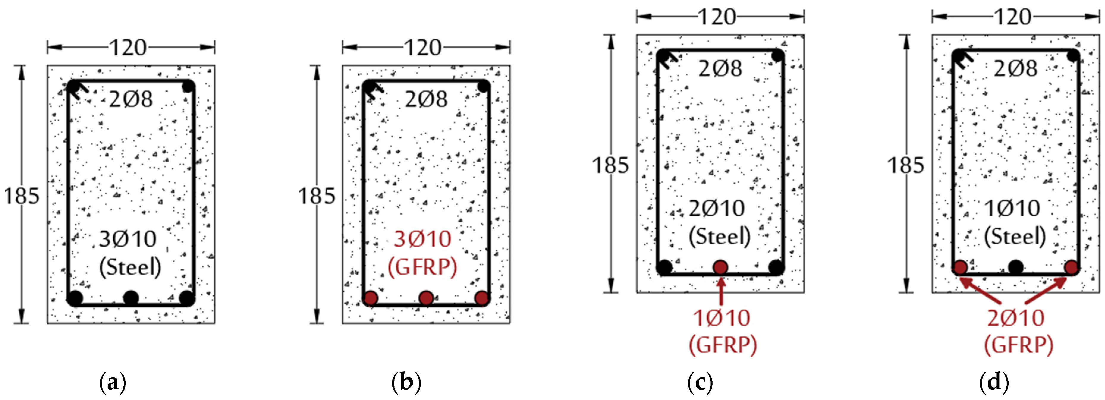
The rebar details of the tested beams are presented in Table 2 and Figure 3. As previously mentioned, the normal concrete (NC) beams (B-3S, B-3G, B-2G1S, and B-1G2S beams) had the same reinforcement details and dimensions as the present FRC beams (BFRC-3S, BFRC-3G, BFRC-1G2S, and BFRC-2G1S beams). For additional details regarding the NC beams’ design and detailing, refer to Abadel [9]. The NC beams will be used as control specimens to compare with current FRC beams in order to evaluate the effect of hybrid fibers on the flexural behavior of FRC beams reinforced with hybrid bars (GFRP and steel).
Four FRC beams of 120 mm × 185 mm and an overall length of 1.5 m were fabricated. All FRC beams utilized two 8 mm diameter compression bars, as shown in Table 2.
The FRC beams’ tension reinforcement employed hybrid configurations of steel and GFRP bars. Each beam contained three main rebars arranged in a single layer, accommodated in the beam width. The first FRC beam (BFRC-3S) was prepared using three steel bars. The second FRC beam (BFRC-3G) had three GFRP bars and the third FRC beam (BFRC-1G2S) had one GFRP and two steel rebars, while the fourth FRC beam (BFRC-2G1S) had two GFRP and one steel rebar. A concrete cover of 20 mm was provided over the longitudinal bars. Thus, the reinforcing ratio ranged from 0.41% to 1.23% for steel and GFRP bars, based on the effective depth.
The beams were designed at approximately one-third of the full scale to ensure manageable laboratory testing while maintaining geometric and reinforcement similarity with prototype dimensions. This scale was selected to preserve the fundamental stress–strain behavior and failure mechanisms representative of full-scale beams, as supported by established similitude principles in structural testing. Although size effects can influence cracking patterns and ultimate load, the chosen scale provides a reliable basis for comparative analysis among test variables. Furthermore, the study focused on the relative performance of hybrid FRC configurations rather than absolute capacity values, ensuring that the observed trends remain valid for larger structural members.

2.4. Specimen Preparation

All beams were prepared from the same batch of concrete used in the preparation of the NC beams of the previous study [9]. To ensure uniform dispersion of fibers within the concrete matrix and to prevent balling or clustering, fibers were gradually introduced into the mixer during the final stage of wet mixing. The mixing process continued for approximately 3–4 min after all fibers were added to achieve homogeneous distribution. Visual inspections were performed during casting to confirm the absence of fiber agglomeration. After demolding, the surface of each specimen was examined to verify even fiber distribution throughout the concrete mass. No signs of fiber segregation or balling were observed, indicating that the adopted mixing procedure was effective in achieving consistent fiber dispersion in all batches. The slump of FRC varied from 75 to 90 mm. The beams were cast in a single layer. A portable vibrator was employed to eliminate entrapped air and ensure proper compaction. Subsequent to the casting of the beams, surfaces were levelled using a trowel and covered with a damp burlap. The formwork was removed after 24 h and the beams were subsequently cured for 28 days in accordance with the relevant standard [39].

2.5. Test Setup and Procedures

The FRC beams were specifically designed to fail in flexure and instrumented accordingly. Thus, the beams were fitted with two strain gauges that recorded strain in the bars (GFRP and steel) at the beams’ midspan. The curvature of the FRC beam was measured with two lateral LVDTs (LVDT-1, 2) positioned near the top and bottom of the beam in the pure flexural region. The mid-span vertical deflection was recorded using LVDT-3. The FRC beams were simply supported on two steel cylindrical rollers, providing an effective span of 1400 mm with a 50 mm overhang at each end. The FRC beams were subjected to two-point loads using 2000 kN capacity AMSLER test equipment (Alfred J. Amsler & Co., Schaffhausen, Switzerland). The test instrumentation layout and test setup are depicted in Figure 4. The load was applied under a displacement control approach, applying load at 0.5 mm/min to enable accurate data acquisition and crack monitoring during testing.

3. Results and Discussion

The NC beams of the first author’s previous study [9] will be used as control beams to compare with the current FRC beams in order to evaluate the effect of hybrid fibers on the flexural characteristics of FRC beams.

3.1. Failure Patterns

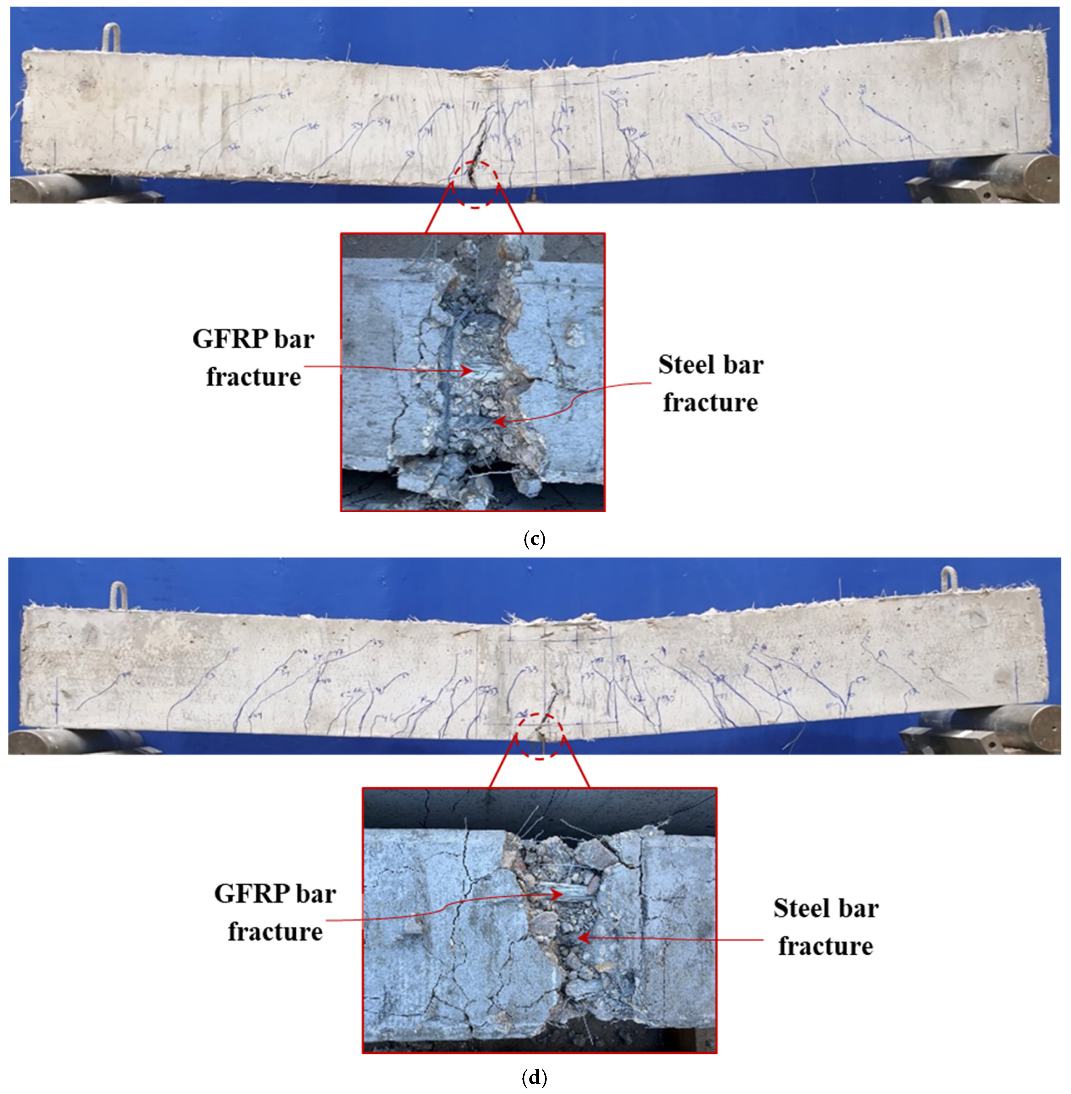
The ultimate crack propagation at failure for all tested FRC beams is illustrated in Figure 5. The crack patterns for all beams are approximately identical. Typically, the initial vertical cracks in all beams appeared at the midspan and propagated towards the supports with increasing load. The first-crack loads of these beams varied from 17.9% to 36.1% of the peak load, P m a x . For the beams BFRC-3S, BFRC-1G2S, BFRC-2G1S, and BFRC-3G, the first-crack loads were 24 kN (36.1% of P m a x ), 20 kN (27.9% of P m a x ), 19 kN (22.0% of P m a x ), and 17 kN (17.9% of P m a x ), respectively. Further loading beyond the first-crack load produced flexural shear cracks, which deepened and widened until a dominant flexural crack developed in the pure bending moment region at failure load. It was noted that the cracks expanded rapidly subsequent to the steel rebars’ yielding, when present, ultimately leading to the failure of the beams, as illustrated in Figure 5. Furthermore, the presence of GFRP bars led to increased crack propagation.
The FRC beams, reinforced with steel bars (BFRC-3S), exhibited typical ductile flexural tension failure, characterized by the yielding of the tensile steel bars, which was accompanied by the progressively widening of the primary flexural crack, followed by the steel bar fracture (Figure 5a). Similarly, the BFRC-3G beam, reinforced solely with GFRP bars, failed in flexural tension mode, with the rupture of GFRP bars and slight concrete crushing observed near the maximum moment region, as illustrated in Figure 5b. The hybrid FRC beams (BFRC-2G1S and BFRC-1G2S) also demonstrated flexural tension failure, which is consistent with the designed failure pattern. In these beams, the GFRP bar(s) fractured first, as the fracture strain of the GFRP bars was less than the fracture strain of the steel bars. The abrupt fracture of the GFRP bar(s) resulted in a stress redistribution to the steel bar(s), causing its fracture as well, as seen from Figure 5c,d.
Comparative analysis revealed that the BFRC-3S beam exhibited relatively fewer cracks at rather larger crack spacing, whereas the BFRC-3G beam displayed a substantially greater number of cracks with reduced spacing. The spacing and number of cracks in the hybrid beams (BFRC-1G2S and BFRC-2G1S) fell between those of the BFRC-3S and BFRC-3G beams, as seen from Figure 5. As the reinforcement ratio of GFRP bars in hybrid beams increases from 0.41% to 1.23%, the number of cracks progressively increased at reduced spacing. These findings align with the findings of Ruan et al. [28] and Wei et al. [4].
The inclusion of hybrid fibers (steel and polypropylene) significantly enhanced the properties of the concrete, improving tensile strength, crack resistance, and durability under aggressive conditions [40,41]. The fibers avoided brittle failure (as observed in NC beams) and made it fail in ductile mode by bridging cracks, transferring stresses across crack planes and delaying microcrack propagation until ultimate failure. Consequently, FRC beams exhibited minimal visible concrete crushing in the compression zone, which agrees with findings noted in prior investigations [32,35,42,43]. At ultimate load, the presence of fibers reduced crack width and limited crack propagation, resulting in improved overall ductility. Figure 6 compares the first-crack load of the FRC beams with that of the NC beams from the previous study [9]. The results indicate the following: (i) hybrid fiber reinforcement in FRC beams delayed cracking relative to their NC counterparts, with the first-crack load (expressed as a percentage of the peak load) increasing by 6.0–13.0% (the maximum of 13%, being observed for the beam without GFRP bars); (ii) enhancing the GFRP bar ratio reduced the first-crack load percentage in both NC and FRC beams, with values decreasing from 36.1% (for 0% GFRP bars) to 17.9% (for 100% GFRP bars) in FRC beams, and from 23.1% (for 0% GFRP bars) to 11.9% (for 100% GFRP bars) in NC beams. The first-crack load of NC as well as the FRC beams are presented in Table 3.
While the present study is experimental, previous numerical investigations have employed various approaches to simulate cracking and post-peak behavior in concrete beams. Cohesive interface and phase-field models [44] accurately capture crack initiation and opening based on localized fracture mechanics, whereas XFEM-based methods [45] allow mesh-independent simulation of crack growth and damage evolution. For hybrid steel–GFRP beams, such models can enhance our understanding of crack initiation, tension softening, and post-peak load transfer beyond what is achievable through experiments alone.

3.2. Load–Deflection Response

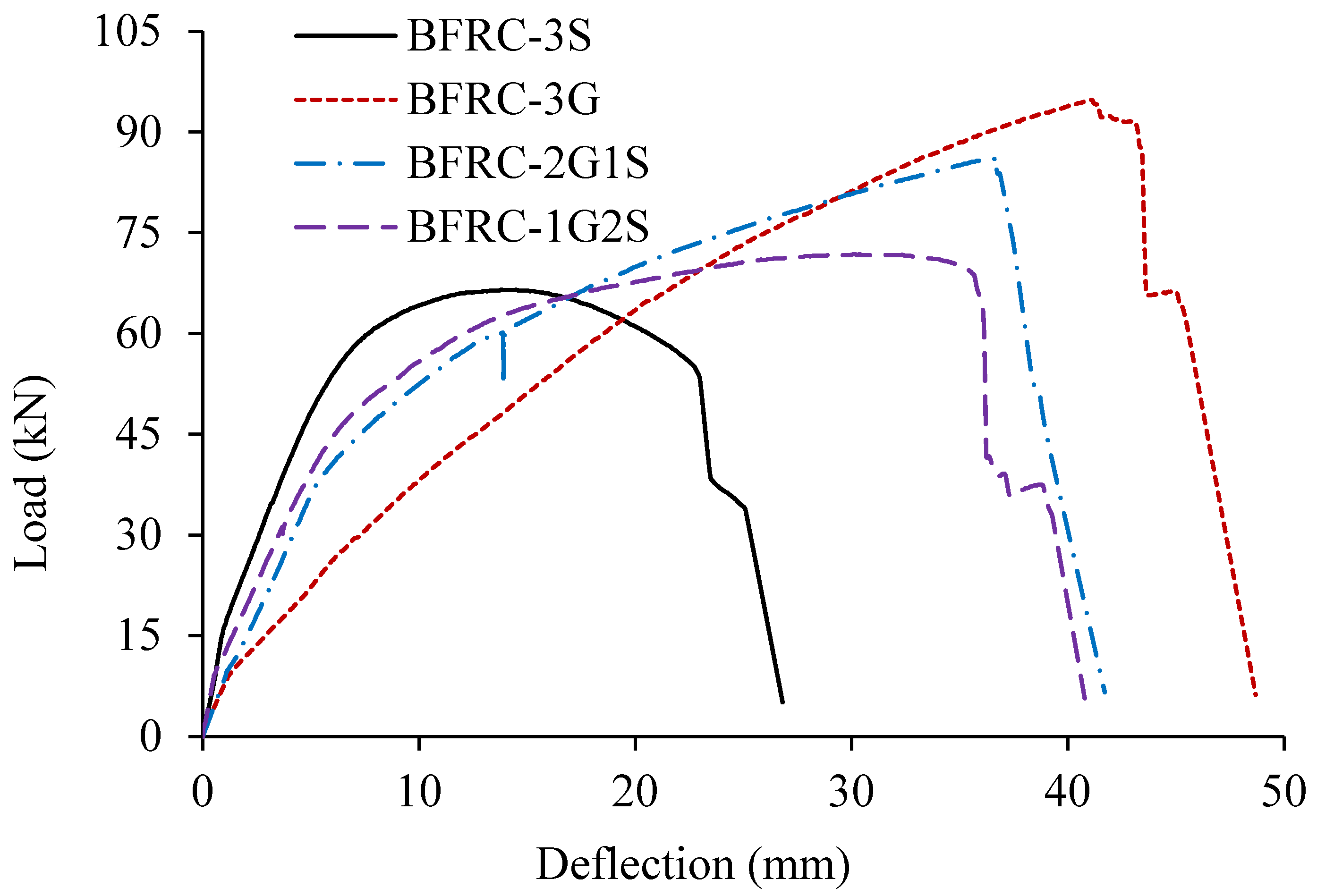
The load–deflection curves for all of the FRC beams are illustrated in Figure 7. For the BFRC-3S beam (steel FRC beam), the relationship was approximately linear up to first cracking. As the load increased, the curve continued to rise, reaching a maximum load of 66.5 kN at a mid-span displacement of 13.8 mm, followed by a progressive decline until failure of the beam. The BFRC-3G (GFRP-FRC) beam displayed an initial short steep linear response, indicating high initial stiffness (though less than all other beams), followed by a near-linear rise to a maximum load of 94.8 kN at 41.1 mm deflection before a sharp drop.
The load–deflection curves of the hybrid FRC beams (BFRC-1G2S and BFRC-2G1S) generally demonstrate three stages. The first stage is an approximately linear response up to first cracking, followed by a nonlinear second stage until reaching the maximum load capacity, which was 86.3 kN and 71.8 kN at deflections of 36.6 and 30.1 mm for the BFRC-2G1S and BFRC-1G2S beams, respectively. In the hybrid beam with two steel bars (BFRC-1G2S), a more pronounced horizontal plateau was observed compared with the steel-only beam (BFRC-3S). However, when only one steel bar was used (BFRC-2G1S), the plateau transitioned into a gradual load increase. In the beam reinforced solely with GFRP bars (BFRC-3G), no plateau was observed; instead, the load continued to rise almost linearly with a slightly decreasing slope until a sudden drop occurred. This trend of a gradual increase followed by abrupt load loss was consistent across all beams containing GFRP bars.
The BFRC-3G, BFRC-2G1S, and BFRC-1G2S beams exhibited an increase in the load-carrying capacity of 42.6%, 29.8%, and 8.0%, respectively, in comparison to the steel FRC beam (i.e., BFRC-3S). Their ultimate deflections were also higher by 81.6%, 52.1%, and 55.5% for the BFRC-3G, BFRC-2G1S, and BFRC-1G2S beams, respectively, demonstrating the beneficial effect of GFRP reinforcement on deformability. Thus, the hybrid FRC beams show a performance that falls between the steel FRC beam (having 0% GFRP bars) and the GFRP-FRC beam (having 100% GFRP bars).
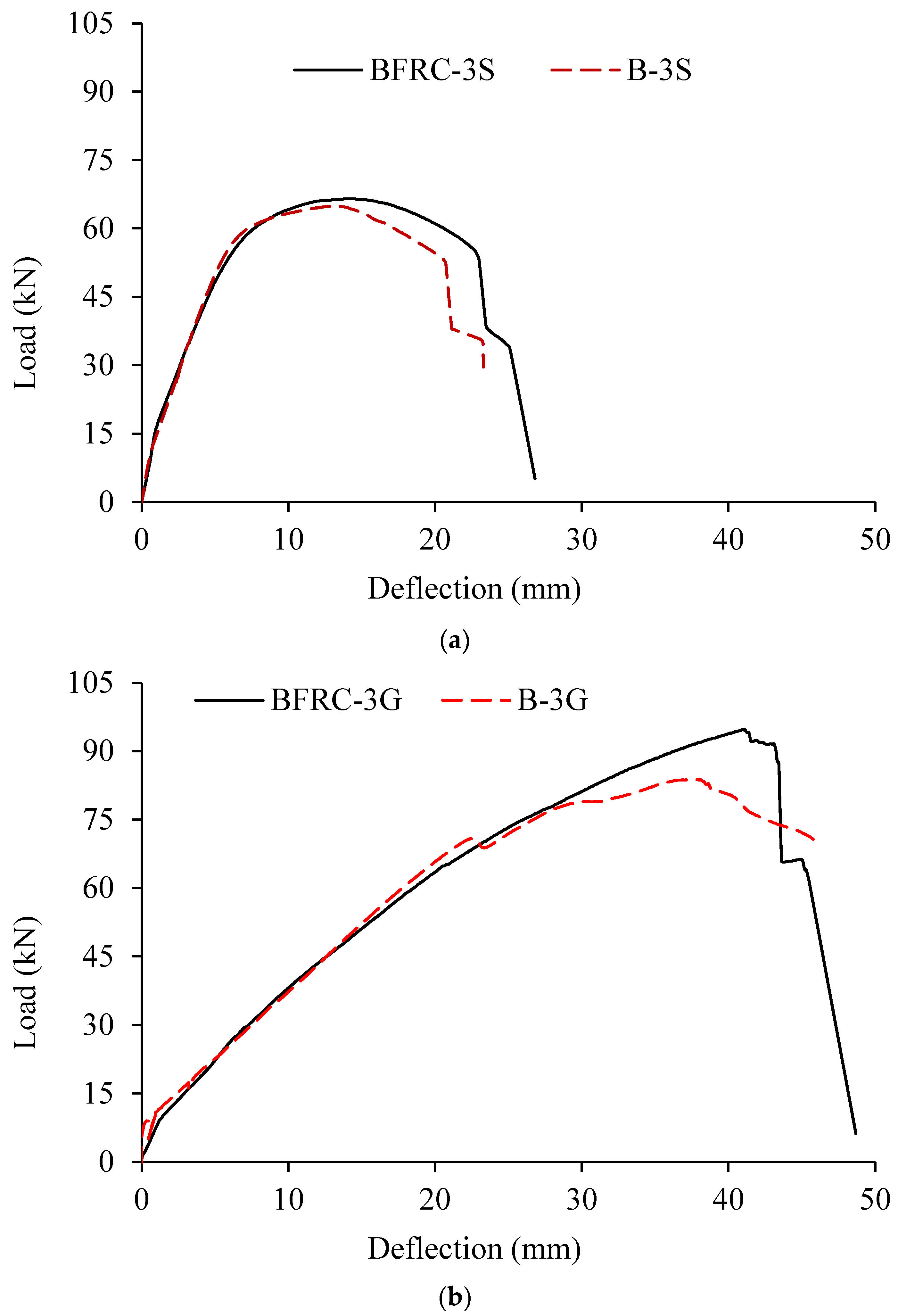
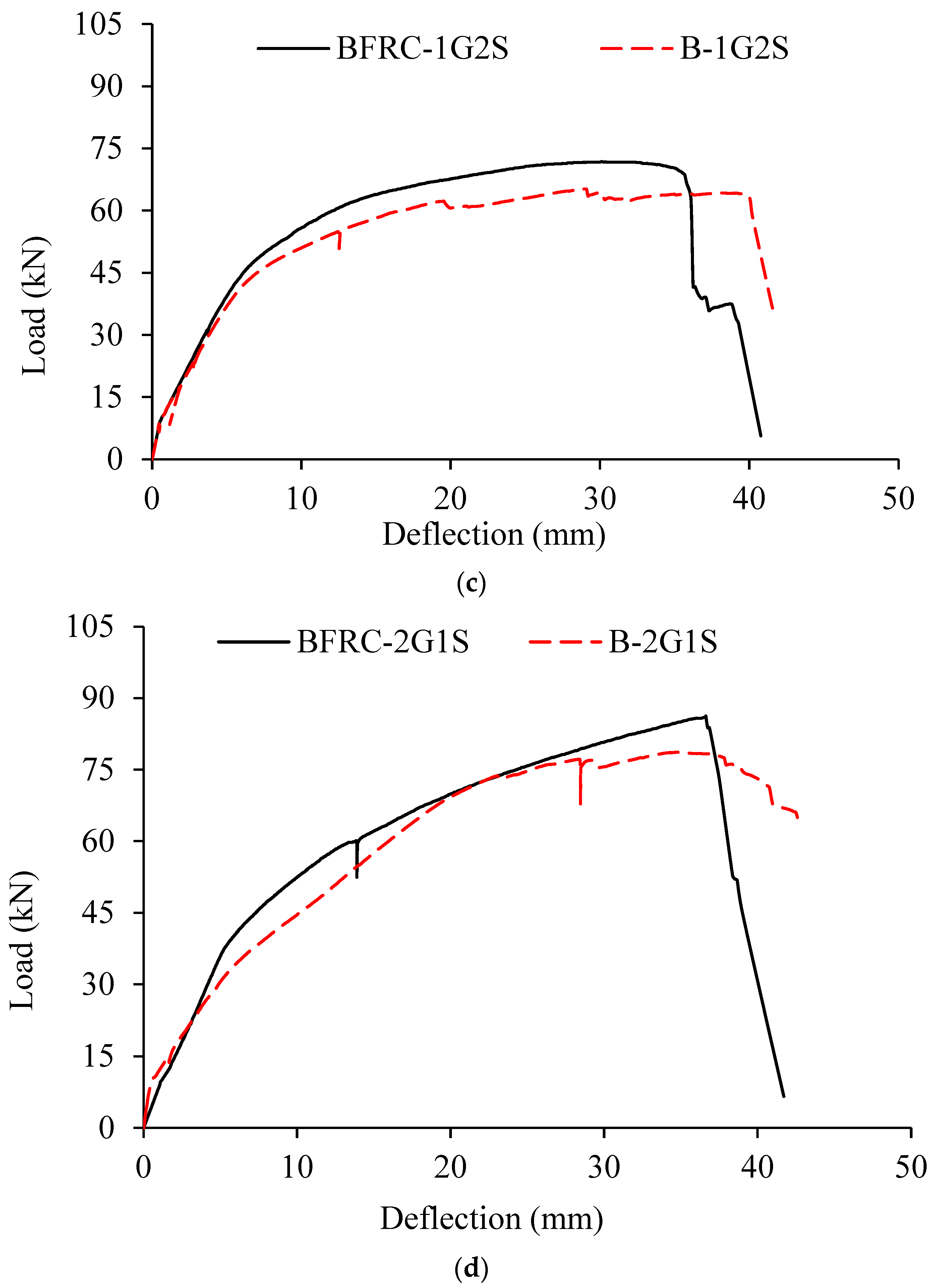
Figure 8 compares the load–deflection responses of NC and FRC beams, while Figure 9 compares their peak loads. The peak loads ( P m a x ) of NC as well as the FRC beams are presented in Table 3. Figure 8 and Figure 9 demonstrate the superior structural performance of FRC beams over NC beams, as the peak loads ( P m a x ) of the FRC beams exceeded those of their NC counterparts by 2.4% to 13.2% (Figure 9). This improvement is due to the presence of hybrid fibers, which enhanced bond efficiency, delayed microcrack initiation, and reduced crack propagation, consistent with previous studies [32,35,42,43]. The improved ductility of FRC beams is further reflected in their higher energy dissipation, represented by the larger area under the load–deflection curves, as discussed in the next section. Abdel-Karim et al. [46] also reported that hybrid reinforcement and hybrid polypropylene fibers significantly improved peak load, aligning with the present findings.
The LVDTs used to measure mid-span deflection had a stroke capacity of ±50 mm. As the maximum recorded displacement approached this limit, the LVDTs were readjusted during testing when they were nearly compressed to their full capacity.

3.3. Load–Strain Response of the Bars

Figure 10 illustrates the load–strain relationships and accompanying deflection for all FRC beams. For the BFRC-3S beam (i.e., reinforced with steel bars only), the strain in the longitudinal steel bars increased almost linearly with the applied load up to yielding, followed by a sharp rise until bar fracture at the peak load, indicated by an abrupt decline in strain. The maximum tensile microstrain in the steel bars reached 17,449, exceeding the yield strain, confirming that the bars carried load beyond yielding until fracture. At peak load (approximately 14 mm deflection), two steel bars fractured (Figure 10a), while the third uninstrumented bar likely remained active, allowing the beam to still carry the load and deflect further until its sudden failure at 23 mm, presumably upon fracture of the third steel bar. Minimal strain was recorded in the stirrups, consistent with the flexural failure mode.
In the BFRC-3G beam (GFRP-reinforced), the load–strain response followed almost the same trend as the load–deflection response until reaching a maximum microstrain of 19,556 (after ignoring sharp spike), well above the fracture strain of GFRP bars (Figure 10b). In the hybrid beams (BFRC-1G2S and BFRC-2G1S), the strain in the steel bars increased almost linearly up to yielding, followed by increase in the slope until fracture (Figure 10c,d). The yielding of steel bars caused a reduction in the stiffness of the beam, as seen from the reduction in the gradient of the load–deflection curve. The microstrains in the steel bars recorded at fracture were 52,977 in BFRC-2G1S and 34,885 in BFRC-1G2S, which are higher than those recorded in BFRC-3S; this could be due to the presence of GFRP bars which delayed sudden rupture of the steel bars. In BFRC-1G2S, the steel bar remained active until peak load since only one GFRP bar was present, whereas in BFRC-2G1S the lone steel bar fractured before peak load as the two GFRP bars carried the load. In both hybrid beams, the microstrain in the GFRP bars increased nearly linearly up to fracture at peak load, recording 23,861 in BFRC-1G2S and 25,289 (ignoring spike) in BFRC-2G1S, both exceeding the nominal fracture strain. Up to steel yielding, the strains in GFRP and steel bars were comparable; beyond yielding, steel strains rose sharply while GFRP strains continued at the same rate, resulting in lower relative values. Yielding of steel did not alter the growth rate of GFRP strain but reduced beam stiffness, as indicated by the change in the slope of the load–deflection curve.
An interesting observation made above is that the strains recorded in GFRP bars at fracture exceeded their experimentally determined fracture strain. This can be explained by the difference between bar failure in direct tension and in beam flexure. While steel bars exhibit nearly uniform strain across the cross-section until failure, GFRP bar failure in flexure is progressive: fibers at the bar’s tensile face (bottom) fracture first, with failure propagating upward through the cross-section. Since the strain gauges were affixed to the bottom surface, they continued to register increasing strain even after partial fiber fracture, as the gauge remained bonded and the entire cross-section had not yet failed.
No significant strain was observed in the stirrups, as the failure mode for all of the FRC beams was attributed to flexural tension failure (Figure 10). Research indicates that using longitudinal GFRP bars as a substitute for steel bars influences the overall performance of FRC beams, improving ductility—attributable to the strains experienced in the GFRP bars [30,47,48].

3.4. Ultimate Bending Moment

Prior studies [4,19,24] have shown that hybrid RC beams follow the equivalent rectangular stress block recommended in the design code [49]. The stress in the GFRP bars ( f f ) and ultimate prediction bending moment capacity ( M u , p r e d ) were calculated from the equilibrium of the internal forces in the beam cross-section at the limit state using Equations (1) and (2). A detailed derivation of the two equations is provided in [24]. It should be noted that these equations neglect reinforcement in the compression zone and are applicable only to beams of rectangular sections.
M u , p r e d = ρ f f f + ρ s f y 1 0.59 ρ f f f + ρ s f y f c b d 2
f f = 1 4 A s f y A f + E f ε c u 2 + 0.85 β 1 f c ρ f A s f y A f E f ε c u 1 2 A s f y A f + E f ε c u f f u
where ρ f is the GFRP bar ratio; ρ s represents the steel bar ratio; b is the beam width; d is the effective depth; A s is the area of the steel reinforcing bars; A f is the area of the GFRP reinforcing bars; ε c u is the concrete’s ultimate compressive strain; β 1 is the ratio of the depth of the equivalent stress block in concrete to the depth of neutral axis; f f u   is the GFRP bars’ tensile strength. Table 3 shows the ultimate experimental ( M u , e x p ) and predicted ( M u , p r e d ) bending moments of FRC and NC beams.
The ratio of experimental to predicted moment ranges from 0.91 to 1.00 for FRC and 1.03 to 1.26 for NC beams, indicating good agreement and confirming the reliability of the predictive equations for RC beams with hybrid reinforcement and with or without fibers. The B-3S beam recorded the highest ratio (1.26), which may be attributed to experimental variability in material strength or microcracking near the loading points. It could also be attributed to ignoring the strength enhancement in the steel rebars beyond the yield stage, as the behavior of steel rebars was assumed as elastic–perfectly plastic. This suggests that further refinement of the predictive equation may be required for steel-reinforced NC beams, especially considering cracking near loading points.

3.5. Moment–Curvature Relationship

The moment–curvature relationships of the FRC beams were derived from strains recorded by the two lateral LVDTs (LVDT-1 and LVDT-2), while the applied moment was obtained from the applied load. The curvature ( ) was determined using the following equation:
= ε y = δ b δ t g y
where δ b and δ t are the lateral displacements recorded by the bottom and top LVDTs, g is the longitudinal gauge length of the lateral LVDTs (=50 mm), and y is the 130 mm vertical distance between the two lateral LVDTs. A moving average filter (window size = 3 data points) was applied to reduce signal noise in curvature computation.
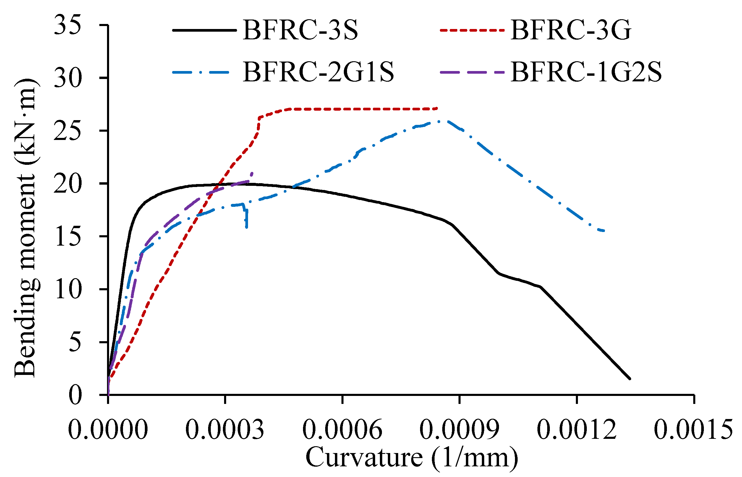
Figure 11 presents the moment–curvature curves, which closely follow the previously discussed load–deflection behavior. The initial stiffness is correlated with the proportion of GFRP reinforcement: BFRC-3S (0% GFRP) exhibited the highest stiffness due to the presence of three steel bars, whereas BFRC-3G (100% GFRP) showed the lowest due to the lower elastic modulus of the GFRP bars. Between the hybrids, BFRC-2G1S had lower initial stiffness than BFRC-1G2S owing to its higher GFRP content. The linear stage of moment–curvature ended with concrete cracking, after which stiffness was governed by crack propagation and rebar stresses.
Post-cracking, BFRC-3S displayed a reduced gradient and plateau, while the hybrid beams (BFRC-1G2S and BFRC-2G1S) showed nonlinear rises. The response of BFRC-2G1S was followed by a gradual decline, whereas the BFRC-1G2S curve was truncated due to LVDT displacement. BFRC-3G maintained a nearly linear trend up to its maximum moment, beyond which a plateau formed, though the record was cut short by LVDT displacement. Among all beams, post-cracking stiffness ranked highest in BFRC-3S, intermediate in the hybrids, and lowest in BFRC-3G.
These results confirm that a higher steel-to-GFRP ratio improves post-cracking stiffness and ductility. In hybrid beams, GFRP bars contributed to load capacity after steel yielding, while steel reinforcement enhanced stiffness and delayed GFRP rupture. Increasing the proportion of steel reinforcement is therefore advisable to limit excessive deformation and mitigate brittle GFRP failure. These findings align with those reported by Kara et al. [19].

3.6. Ductility

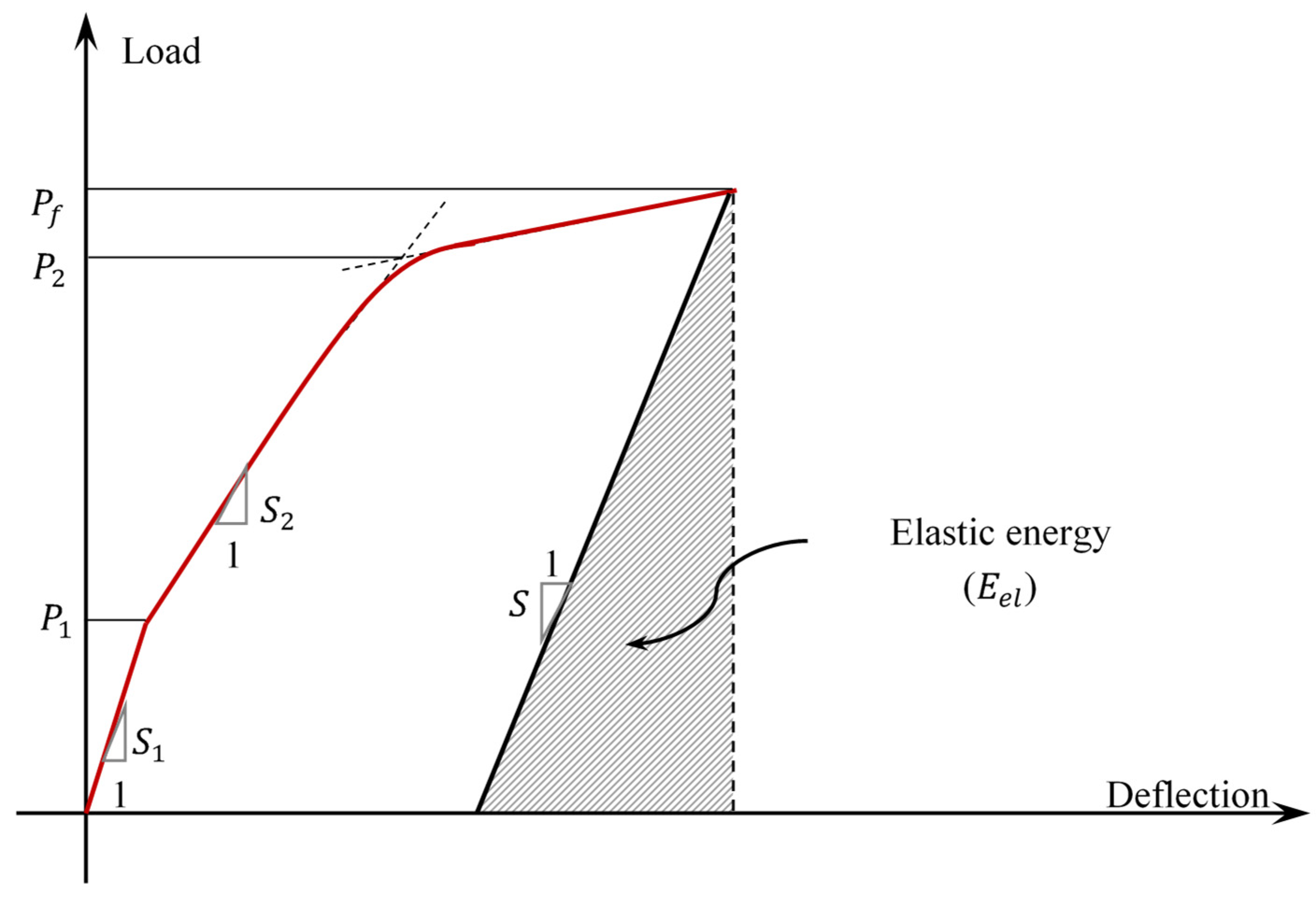
Ductility is a key design parameter in RC structures, reflecting the capacity of a member to undergo substantial deformation before failure while continuing to sustain load. A highly ductile RC member dissipates energy, providing visible warning signs prior to collapse. As the flexural response of FRC beams with hybrid reinforcement differs markedly from that of steel-reinforced FRC beams, the conventional procedure of ductility estimation cannot be used. Instead, an energy-based approach was utilized to assess the flexural ductility of hybrid FRC beams. Following the method proposed in Ref. [50], the load–deflection curve was segmented into three linear parts for energy computation (Figure 12) and the energy ductility index ( μ E ) was calculated using the following Equations (4)–(6):
μ E = 0.5 E T E e l + 1
S = P 1 S 1 + P 2 P 1 S 2 P 2
E e l = 0.5 P f 2 S
where E e l is the elastic energy (Figure 12); E T is the area under the load–deflection curve (total energy absorbed); S is the hypotenuse of slope at beam’s failure; S 1 and S 2 are the slopes of the first two lines in the curve, respectively (Figure 12); P 1 and P 2 are the loads corresponding to the intersection of the first two lines and second and third lines, respectively (Figure 12); and P f is the failure load.
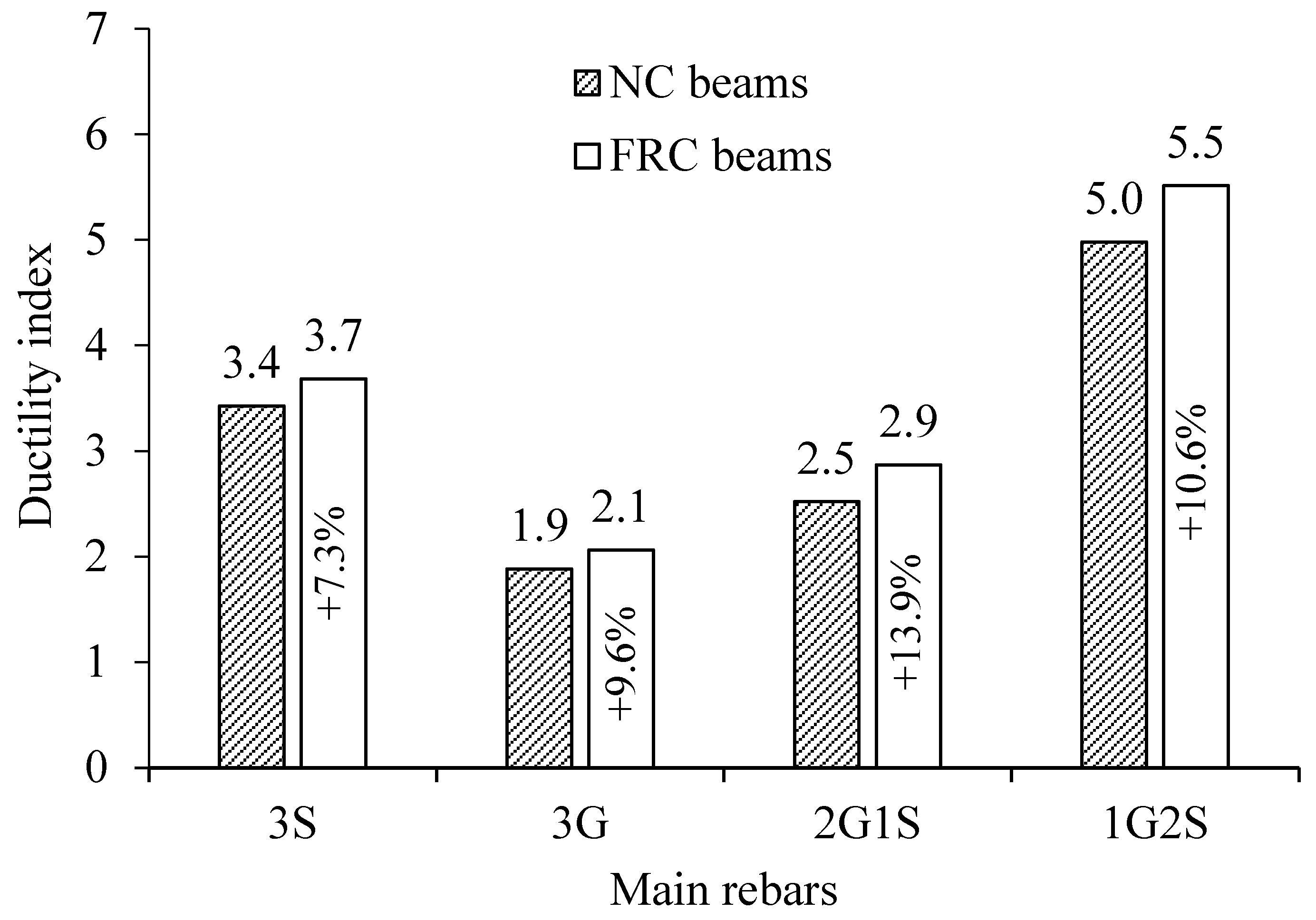
Table 3 and Figure 13 present the μ E values of all beams as determined by the method described above. The results indicate that μ E generally increases with the number of steel rebars in hybrid FRC beams, highlighting the importance of optimizing the steel-to-GFRP ratio for improved ductility. Among all beams, BFRC-1G2S exhibited the highest μ E , whereas BFRC-3G recorded the lowest. The use of GFRP bars reduced ductility due to their lower elastic modulus compared to steel, with BFRC-3G showing a 44% reduction in μ E relative to BFRC-3S. Furthermore, μ E increased significantly with higher steel content in hybrid beams. Replacing one GFRP bar with a steel bar (BFRC-2G1S) increased the ductility by 39.1%, whereas replacing two GFRP bars with steel bars (BFRC-1G2S) caused significant enhancement in ductility, as it increased by 167.1%. Thus, the ductility of BFRC-1G2S is 92.2% more than that of BFRC-2G1S. These findings are consistent with Fouad et al. [52], who reported that increasing the GFRP ratio up to a certain limit enhances flexural strength but reduces ductility. The addition of limited GFRP reinforcement to steel-reinforced beams (BFRC-1G2S) enhanced ductility by extending the plateau region of the load–deflection curve, which is attributed to the lower modulus and elastic contribution of GFRP after steel yielding. However, as the GFRP ratio increased (BFRC-2G1S and BFRC-3G), the beam response became progressively brittle, as the composite section’s behavior was dominated by the linear–elastic GFRP reinforcement, leading to abrupt rupture once the GFRP bars reached their ultimate strain.
Figure 13 also compares FRC and NC beams, revealing that FRC beams achieved 7.3–13.9% higher μ E values. Hybrid fibers contributed to these improvements, with μ E increases of 7.3%, 9.6%, 13.9%, and 10.6% for BFRC-3S, BFRC-3G, BFRC-2G1S, and BFRC-1G2S, respectively, relative to their NC counterparts (B-3S, B-3G, B-2G1S, B-1G2S). The improved performance is attributed to the enhanced bond efficiency provided by the hybrid fibers, which delay microcrack initiation, bridge cracks, and inhibit crack propagation, in agreement with previous studies [32,35,42,43].
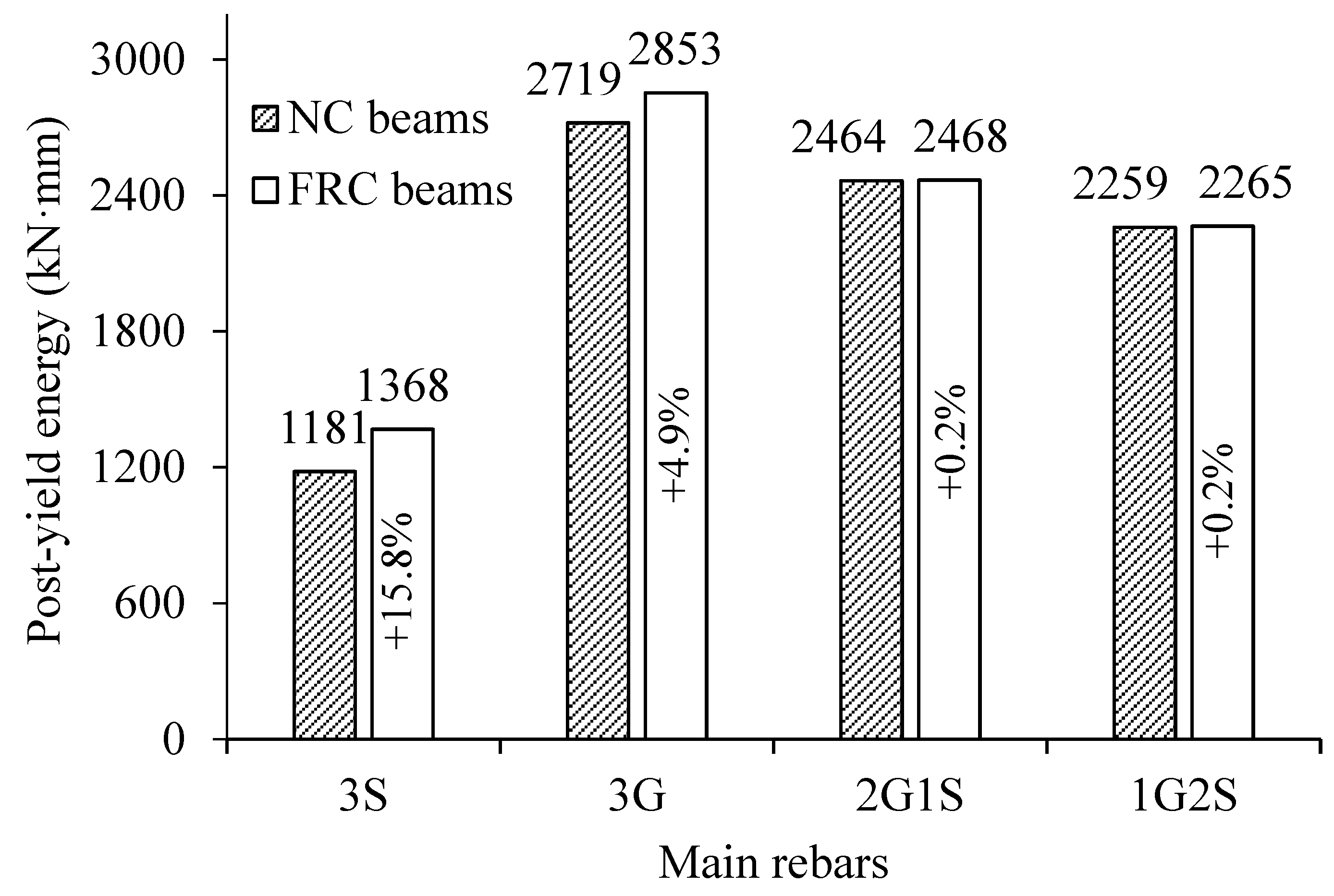
Bar charts illustrating the post-yield energy absorption of the NC and FRC beams are presented in Figure 14. A comparison between NC and FRC beams reveals that the inclusion of fibers increased the energy absorption by 15.8% in the beam reinforced with three steel bars (3S) and by 4.9% in the beam reinforced with three GFRP bars (3G), while the hybrid-reinforced beams (2G1S and 1G2S) exhibited negligible improvement. The observed increase in energy absorption is attributed to the fiber addition in FRC, which enhanced the post-cracking ductility and energy dissipation capacity. This further confirms the superior ductility and deformation capacity of FRC beams. Furthermore, Figure 14 shows a notable increase in energy absorption when the 3S reinforcement was replaced with 3G in both NC and FRC beams, primarily due to the higher tensile strength of GFRP bars. Conversely, as the proportion of GFRP bars decreased in the hybrid beams (2G1S and 1G2S), the overall energy absorption reduced, corresponding to the increased presence of steel bars with lower tensile strength.

4. Conclusions

This study examined the flexural behavior of FRC beams reinforced with hybrid bars. The experimental results of this study lead to the following primary conclusions:
  • All beams failed in flexural tension mode as designed, with yielding of steel bars and fracture of GFRP reinforcement at ultimate strain, accompanied by major crack widening before rupture.
  • Incorporating hybrid fibers into concrete improved its toughness and ductility, transforming brittle failure into ductile behavior and reducing concrete crushing in the compression zone.
  • Hybrid FRC beams exhibited a clear horizontal plateau between yielding and ultimate load, reflecting enhanced ductility that increased with the steel reinforcement ratio.
  • Hybrid fibers effectively delayed crack initiation, restricted crack widening and propagation, and increased load capacity by up to 13.2% compared to normal concrete beams.
  • The stiffness of the hybrid FRC beams was positioned between that of the corresponding steel FRC beam and the GFRP-FRC beam. It is observed that a higher ratio of steel-to-GFRP bars correlates with an increase in stiffness. It is recommended to increase the steel bars to mitigate the risk of excessive deformation, which may lead to brittle rupture of GFRP bars.
  • The findings indicate that the energy-based ductility index ( μ E ) of the hybrid FRC beams generally rises with an increase in the number of steel bars. The use of GFRP bars reduced beam ductility, with BFRC-3G exhibiting a 44% drop in μ E compared to BFRC-3S. Introducing steel into hybrid beams improved ductility substantially: replacing one GFRP bar increased μ E by 39.1%, while replacing two bars enhanced it by 167.1%, making BFRC-1G2S 92.2% more ductile than BFRC-2G1S. In addition, the μ E values for the FRC beams show a clear superiority compared to the NC beams, with an increase of up to 13.9%.
  • This study provides practical insights into the performance of FRC beams with hybrid steel–GFRP reinforcement. The results show that partial replacement of steel with GFRP bars enhances ductility and energy absorption, while fibers further improve crack control and toughness. These findings support the broader adoption of hybrid reinforcement systems for durable, corrosion-resistant, and ductile concrete structures.
  • Future studies are recommended to explore the influence of varying proportions and types of FRP and steel reinforcement, including configurations with FRP bars placed in the bottom layer and steel bars positioned in the upper layer to enhance corrosion resistance. Additionally, investigating different hybrid combinations of fibers within the concrete matrix could further optimize the mechanical performance and durability of hybrid FRC beams reinforced with hybrid rebars.

Author Contributions

Conceptualization, methodology, investigation, validation, visualization, writing—original draft preparation, A.A. Methodology, validation, visualization, writing—original draft preparation, H.A. Investigation, visualization, writing—review and editing, H.E. Investigation, writing—review and editing, T.A. Investigation, writing—review and editing, S.M. Supervision, funding acquisition, writing—review and editing, Y.A.-S. All authors have read and agreed to the published version of the manuscript.

Funding

This research was funded through the Ongoing Research Funding Program—Research Chairs (ORF-RC-2025–0400), King Saud University, Riyadh, Saudi Arabia.

Data Availability Statement

The data presented in this study are available on request from the corresponding author.

Acknowledgments

The authors gratefully acknowledge the funding received through the Ongoing Research Funding Program—Research Chairs (ORF-RC-2025–0400), King Saud University, Riyadh, Saudi Arabia.

Conflicts of Interest

The authors declare no conflicts of interest.

References

  1. Hosseinzadehfard, E.; Mobaraki, B. Corrosion performance and strain behavior of reinforced concrete: Effect of natural pozzolan as partial substitute for microsilica in concrete mixtures. Structures 2025, 79, 109397. [Google Scholar] [CrossRef]
  2. Yan, L.; Deng, W.; Wang, N.; Xue, X.; Hua, J.; Chen, Z. Anti-corrosion reinforcements using coating technologies—A review. Polymers 2022, 14, 4782. [Google Scholar] [CrossRef]
  3. Abbas, H.; Elsanadedy, H.; Alaoud, L.; Almusallam, T.; Al-Salloum, Y. Effect of confining stirrups and bar gap in improving bond behavior of glass fiber reinforced polymer (GFRP) bar lap splices in RC beams. Constr. Build. Mater. 2023, 365, 129943. [Google Scholar] [CrossRef]
  4. Wei, B.; He, X.; Zhou, M.; Wang, H.; He, J. Experimental study on flexural behaviors of FRP and steel bars hybrid reinforced concrete beams. Case Stud. Constr. Mater. 2024, 20, e02759. [Google Scholar] [CrossRef]
  5. Tomlinson, D.; Fam, A. Performance of Concrete Beams Reinforced with Basalt FRP for Flexure and Shear. J. Compos. Constr. 2015, 19, 04014036. [Google Scholar] [CrossRef]
  6. Soric, Z.; Kisicek, T.; Galic, J. Deflections of concrete beams reinforced with FRP bars. Mater. Struct. 2010, 43, 73–90. [Google Scholar] [CrossRef]
  7. Adam, M.A.; Said, M.; Mahmoud, A.A.; Shanour, A.S. Analytical and experimental flexural behavior of concrete beams reinforced with glass fiber reinforced polymers bars. Constr. Build. Mater. 2015, 84, 354–366. [Google Scholar] [CrossRef]
  8. Pawłowski, D.; Szumigała, M. Flexural Behaviour of Full-scale Basalt FRP RC Beams—Experimental and Numerical Studies. Procedia Eng. 2015, 108, 518–525. [Google Scholar] [CrossRef]
  9. Abadel, A.A. Flexural behaviour of RC beams with a UHPFRC top layer and hybrid reinforcement of steel and glass fiber reinforced polymer bars. Case Stud. Constr. Mater. 2024, 21, e04017. [Google Scholar] [CrossRef]
  10. Said, M.; Shanour, A.S.; Mustafa, T.S.; Abdel-Kareem, A.H.; Khalil, M.M. Experimental flexural performance of concrete beams reinforced with an innovative hybrid bars. Eng. Struct. 2021, 226, 111348. [Google Scholar] [CrossRef]
  11. Dong, H.-L.; Zhou, W.; Wang, Z. Flexural performance of concrete beams reinforced with FRP bars grouted in corrugated sleeves. Compos. Struct. 2019, 215, 49–59. [Google Scholar] [CrossRef]
  12. Said, M.; Adam, M.A.; Mahmoud, A.A.; Shanour, A.S. Experimental and analytical shear evaluation of concrete beams reinforced with glass fiber reinforced polymers bars. Constr. Build. Mater. 2016, 102, 574–591. [Google Scholar] [CrossRef]
  13. Habeeb, M.N.; Ashour, A.F. Flexural Behavior of Continuous GFRP Reinforced Concrete Beams. J. Compos. Constr. 2008, 12, 115–124. [Google Scholar] [CrossRef]
  14. Pecce, M.; Manfredi, G.; Cosenza, E. Experimental Response and Code Modelsof GFRP RC Beams in Bending. J. Compos. Constr. 2000, 4, 182–190. [Google Scholar] [CrossRef]
  15. El Refai, A.; Abed, F.; Al-Rahmani, A. Structural performance and serviceability of concrete beams reinforced with hybrid (GFRP and steel) bars. Constr. Build. Mater. 2015, 96, 518–529. [Google Scholar] [CrossRef]
  16. Sun, Z.; Fu, L.; Feng, D.-C.; Vatuloka, A.R.; Wei, Y.; Wu, G. Experimental study on the flexural behavior of concrete beams reinforced with bundled hybrid steel/FRP bars. Eng. Struct. 2019, 197, 109443. [Google Scholar] [CrossRef]
  17. Ge, W.; Zhang, J.; Cao, D.; Tu, Y. Flexural behaviors of hybrid concrete beams reinforced with BFRP bars and steel bars. Constr. Build. Mater. 2015, 87, 28–37. [Google Scholar] [CrossRef]
  18. Safan, M.A. Flexural behavior and design of steel-GFRP reinforced concrete beams. ACI Mater. J. 2013, 110, 677. [Google Scholar] [CrossRef]
  19. Kara, I.F.; Ashour, A.F.; Köroğlu, M.A. Flexural behavior of hybrid FRP/steel reinforced concrete beams. Compos. Struct. 2015, 129, 111–121. [Google Scholar] [CrossRef]
  20. Lau, D.; Pam, H.J. Experimental study of hybrid FRP reinforced concrete beams. Eng. Struct. 2010, 32, 3857–3865. [Google Scholar] [CrossRef]
  21. Aiello, M.A.; Ombres, L. Structural Performances of Concrete Beams with Hybrid (Fiber-Reinforced Polymer-Steel) Reinforcements. J. Compos. Constr. 2002, 6, 133–140. [Google Scholar] [CrossRef]
  22. Yoon, Y.-S.; Yang, J.-M.; Min, K.-H.; Shin, H.-O. Flexural strength and deflection characteristics of high-strength concrete beams with hybrid FRP and steel bar reinforcement. Spec. Publ. 2011, 275, 1–22. [Google Scholar]
  23. Thamrin, R.; Zaidir, Z.; Iwanda, D. Ductility Estimation for Flexural Concrete Beams Longitudinally Reinforced with Hybrid FRP–Steel Bars. Polymers 2022, 14, 1017. [Google Scholar] [CrossRef] [PubMed]
  24. Pang, L.; Qu, W.; Zhu, P.; Xu, J. Design Propositions for Hybrid FRP-Steel Reinforced Concrete Beams. J. Compos. Constr. 2015, 20, 04015086. [Google Scholar] [CrossRef]
  25. Yang, Y.; Sun, Z.-Y.; Wu, G.; Cao, D.-F.; Zhang, Z.-Q. Flexural capacity and design of hybrid FRP-steel-reinforced concrete beams. Adv. Struct. Eng. 2019, 23, 1290–1304. [Google Scholar] [CrossRef]
  26. Yang, Y.; Sun, Z.; Wu, G.; Cao, D.-F.; Pan, D. Experimental study of concrete beams reinforced with hybrid bars (SFCBs and BFRP bars). Mater. Struct. 2020, 53, 77. [Google Scholar] [CrossRef]
  27. Lu, C.H.; Li, H.; Xu, K.; Xuan, G.Y.; Abdullah, W. Experimental study of flexural behavior and serviceability of hybrid concrete beams reinforced by steel and G/BFRP bars. IOP. Conf. Ser. Mater. Sci. Eng. 2020, 770, 12007. [Google Scholar] [CrossRef]
  28. Ruan, X.; Lu, C.; Xu, K.; Xuan, G.; Ni, M. Flexural behavior and serviceability of concrete beams hybrid-reinforced with GFRP bars and steel bars. Compos. Struct. 2020, 235, 111772. [Google Scholar] [CrossRef]
  29. Qin, R.; Zhou, A.; Lau, D. Effect of reinforcement ratio on the flexural performance of hybrid FRP reinforced concrete beams. Compos. B Eng. 2017, 108, 200–209. [Google Scholar] [CrossRef]
  30. Abbas, H.; Abadel, A.; Almusallam, T.; Al-Salloum, Y. Experimental and analytical study of flexural performance of concrete beams reinforced with hybrid of GFRP and steel rebars. Eng. Fail. Anal. 2022, 138, 106397. [Google Scholar] [CrossRef]
  31. Alwesabi, E.A.; Bakar, B.H.A.; Alshaikh, I.M.H.; Akil, H.M. Impact resistance of plain and rubberized concrete containing steel and polypropylene hybrid fiber. Mater. Today Commun. 2020, 25, 101640. [Google Scholar] [CrossRef]
  32. Alwesabi, E.A.H.; Bakar, B.H.A.; Alshaikh, I.M.H.; Akil, H.M. Experimental investigation on mechanical properties of plain and rubberised concretes with steel–polypropylene hybrid fibre. Constr. Build. Mater. 2020, 233, 117194. [Google Scholar] [CrossRef]
  33. Abadel, A.A.; Abbas, H.; Alshaikh, I.M.H.; Tuladhar, R.; Altheeb, A.; Alamri, M. Experimental study on the effects of external strengthening and elevated temperature on the shear behavior of ultra-high-performance fiber-reinforced concrete deep beams. In Structures; Elsevier: Amsterdam, The Netherlands, 2023; pp. 943–957. [Google Scholar]
  34. Abdullah, G.M.S.; Alshaikh, I.M.H.; Zeyad, A.M.; Magbool, H.M.; Bakar, B.H.A. The effect of openings on the performance of self-compacting concrete with volcanic pumice powder and different steel fibers. Case Stud. Constr. Mater. 2022, 17, e01148. [Google Scholar] [CrossRef]
  35. Alshaikh, I.M.H.; Bakar, B.H.A.; Alwesabi, E.A.H.; Abadel, A.A.; Alghamdi, H.; Wasim, M. An experimental study on enhancing progressive collapse resistance using a steel fiber–reinforced concrete frame. J. Struct. Eng. 2022, 148, 04022087. [Google Scholar] [CrossRef]
  36. ASTM C150-24; Standard Test Method for Portland Cement. American Society for Testing and Materials (ASTM): West Conshohocken, PA, USA, 2024.
  37. ASTM A370-24a; Standard Test Methods and Definitions for Mechanical Testing of Steel Products. American Society for Testing and Materials (ASTM): West Conshohocken, PA, USA, 2024.
  38. ASTM D7205/D7205M-21; Standard Test Method for Tensile Properties of Fiber Reinforced Polymer Matrix Composite Bars. American Society for Testing and Materials (ASTM): West Conshohocken, PA, USA, 2021.
  39. ACI. Guide to External Curing of Concrete; American Concrete Institute: Farmington Hills, MI, USA, 2016. [Google Scholar]
  40. Zhao, S.; Liu, J.; Liu, R. Steel/plastic-steel hybrid fiber UHPC dynamic tensile performance: An experimental and numerical simulation study. J. Build. Eng. 2024, 92, 109706. [Google Scholar] [CrossRef]
  41. Li, J.; Luo, J.; Chen, L.; Fan, X.; Zhu, Y.; Wang, X.; Guo, J. Research on mechanical properties of steel-polypropylene fiber concrete and application of beam structure. Front. Mater. 2024, 11, 1440466. [Google Scholar] [CrossRef]
  42. Shaaban, I.G.; Said, M.; Khan, S.U.; Eissa, M.; Elrashidy, K. Experimental and theoretical behaviour of reinforced concrete beams containing hybrid fibres. Structures 2021, 32, 2143–2160. [Google Scholar] [CrossRef]
  43. El Bakzawy, A.; Makhlouf, M.H.; Mustafa, T.S.; Adam, M. Experimental investigation on the flexural behavior of SFRC beams reinforced with hybrid reinforcement schemes. Eng. Struct. 2024, 309, 118054. [Google Scholar] [CrossRef]
  44. De Maio, U.; Gaetano, D.; Greco, F.; Lonetti, P.; Pranno, A. An adaptive cohesive interface model for fracture propagation analysis in heterogeneous media. Eng. Fract. Mech. 2025, 325, 111330. [Google Scholar] [CrossRef]
  45. Faron, A.; Rombach, G.A. Simulation of crack growth in reinforced concrete beams using extended finite element method. Eng. Fail. Anal. 2020, 116, 104698. [Google Scholar] [CrossRef]
  46. Abdel-Karim, A.H.; Khalil, G.I.; Ewis, A.E.; Makhlouf, M.H. Impact of developed hybrid polypropylene fiber inclusion on the flexural performance of concrete beams reinforced with innovative hybrid bars. Constr. Build. Mater. 2023, 409, 134113. [Google Scholar] [CrossRef]
  47. Abbas, H.; Almusallam, T.; Abadel, A.; Alenzi, S.; Al-Salloum, Y. Shear Strength of Functionally Graded Self-Compacting Concrete Deep Beams Reinforced with Steel and GFRP Bars. Case Stud. Constr. Mater. 2023, 18, e01872. [Google Scholar] [CrossRef]
  48. Abadel, A.; Alenzi, S.; Almusallam, T.; Abbas, H.; Al-Salloum, Y. Shear behavior of self-consolidating concrete deep beams reinforced with hybrid of steel and GFRP bars. Ain. Shams. Eng. J. 2023, 14, 102136. [Google Scholar] [CrossRef]
  49. ACI 440.2R-17; Guide for the Design Construction of Externally Bonded FRP Systems for Strengthening Concrete Structures. American Concrete Institute (ACI): Farmington Hills, MI, USA, 2017.
  50. Naaman, M.; Jeong, A.E. Structural Ductility of Concrete Beams Prestressed with FRP Tendons. In Non-Metallic (FRP) Reinforcement for Concrete Structures: Proceedings of the Second International RILEM Symposium; CRC Press: Boca Raton, FL, USA, 1995; p. 379. [Google Scholar]
  51. Grace, N.F.; Soliman, A.K.; Abdel-Sayed, G.; Saleh, K.R. Behavior and ductility of simple and continuous FRP reinforced beams. J. Compos. Constr. 1998, 2, 186–194. [Google Scholar] [CrossRef]
  52. Fouad, R.; Aboubeah, A.S.; Hussein, A.; Zaher, A.; Said, H. Flexural behavior of RC continuous beams having hybrid reinforcement of steel and GFRP bars. J. Reinf. Plast. Compos. 2023, 42, 1289–1302. [Google Scholar] [CrossRef]
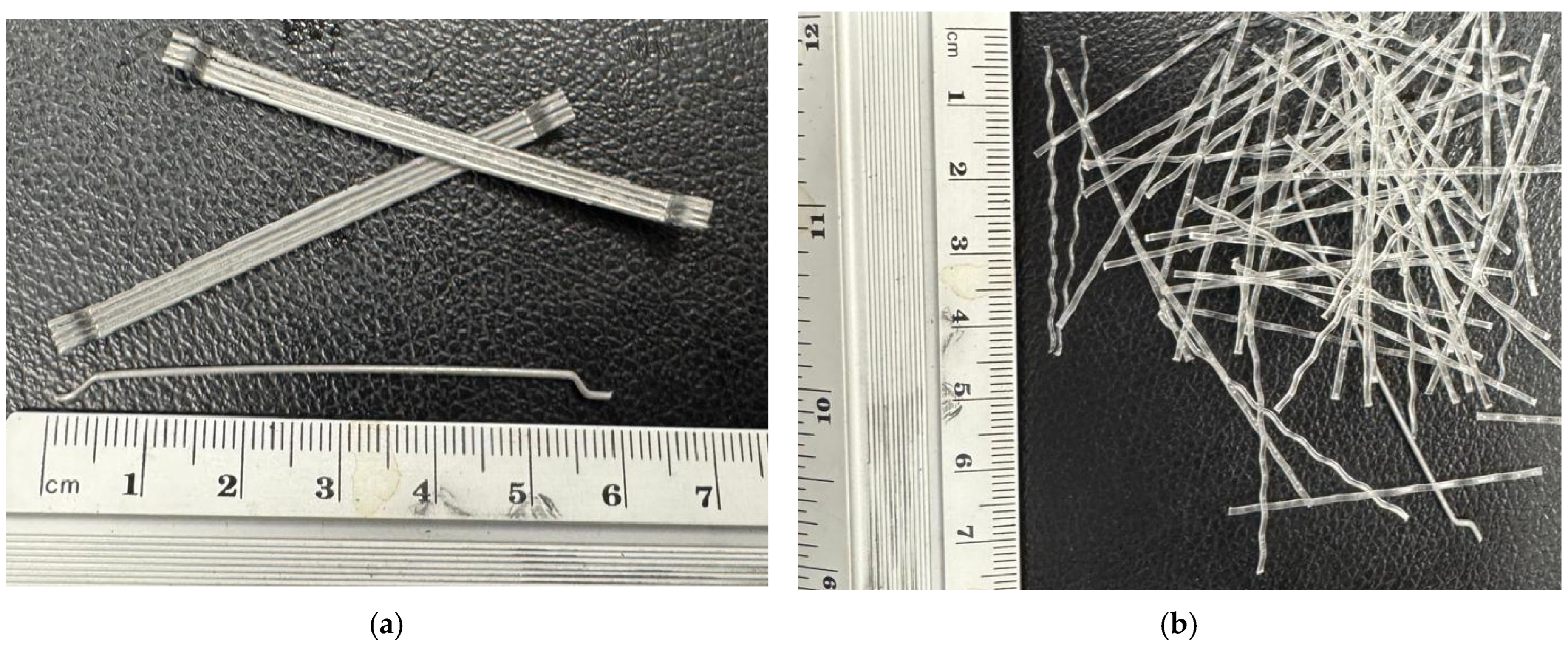
Figure 1. Fibers employed in this study: (a) SF; (b) PP.
Buildings 15 04146 g001
Figure 2. GFRP bar used in the study.
Buildings 15 04146 g002
Figure 3. The reinforcement details of the beams: (a) BFRC-3S; (b) BFRC-3G; (c) BFRC-1G2S; (d) BFRC-2G1S (all dimension in mm).
Buildings 15 04146 g003
Figure 4. (a) Instrumentation details; (b) test setup.
Buildings 15 04146 g004
Figure 5. Failure mode with zoomed view showing the rupture of steel and GFRP bars for different beams: (a) BFRC-3S; (b) BFRC-3G; (c) BFRC-1G2S; (d) BFRC-2G1S.
Buildings 15 04146 g005aBuildings 15 04146 g005b
Figure 6. First-crack load as a ratio of peak load for NC and FRC beams.
Buildings 15 04146 g006
Figure 7. Load–deflection curve for all beams.
Buildings 15 04146 g007
Figure 8. Load–deflection curve for FRC and NC beams: (a) BFRC-3S and B-3S; (b) BFRC-3G and B-3G; (c) BFRC-1G2S and B-1G2S; (d) BFRC-2G1S and B-2G1S.
Buildings 15 04146 g008aBuildings 15 04146 g008b
Figure 9. A comparison of peak load for NC and FRC beams.
Buildings 15 04146 g009
Figure 10. Load–strain and load–deflection response for FRC beams: (a) BFRC-3S; (b) BFRC-3G; (c) BFRC-1G2S; (d) BFRC-2G1S.
Buildings 15 04146 g010aBuildings 15 04146 g010b
Figure 11. Moment–curvature responses for all beams.
Buildings 15 04146 g011
Figure 12. The μ E calculation approach for hybrid RC beams based on Refs. [50,51] (Note: Red line is the load-deflection curve).
Buildings 15 04146 g012
Figure 13. A comparison of ductility index for NC and FRC beams.
Buildings 15 04146 g013
Figure 14. A comparison of post-yield energy absorbed in NC and FRC beams.
Buildings 15 04146 g014
Table 1. Mix ingredients of the FRC mix in kg/m3.
Cement (C)White SandCrushed SandCoarse AggregatesFibersSuper-PlasticizerWater (W)W/C Ratio
10 mm20 mmSFPP
35047031021084058.919.61.815190.50.54
Table 2. Test matrix and specimen details.
Specimen IDConcrete MixTop ReinforcementBottom Reinforcement
Steel BarsGFRP Bars
B-3SNC *2 8
(0.45%)
3 10 (1.23%)-
B-3G-3 10 (1.23%)
B-1G2S2 10 (0.82%)1 10 (0.41%)
B-2G1S1 10 (0.41%)2 10 (0.82%)
BFRC-3SFRC2 8
(0.45%)
3 10 (1.23%)-
BFRC-3G-3 10 (1.23%)
BFRC-1G2S2 10 (0.82%)1 10 (0.41%)
BFRC-2G1S1 10 (0.41%)2 10 (0.82%)
* Test results published in Ref. [9].
Table 3. Test results, predicted BM, and ductility index.
Specimens IDFirst-Crack Load (kN) P m a x   (kN) M u , e x p (kN·m) M u , p r e d (kN·m) M u , e x p M u , p r e d Ductility   Index ,   μ E
B-3S *1564.919.515.41.263.43
BFRC-3S2466.520.020.01.003.68
B-3G *1083.825.123.71.061.88
BFRC-3G1794.828.430.40.942.06
B-2G1S *1278.723.622.91.032.52
BFRC-2G1S1986.325.927.20.952.87
B-1G2S *1465.219.618.51.064.98
BFRC-1G2S2071.821.523.70.915.51
* Test results published in Ref. [9].
Disclaimer/Publisher’s Note: The statements, opinions and data contained in all publications are solely those of the individual author(s) and contributor(s) and not of MDPI and/or the editor(s). MDPI and/or the editor(s) disclaim responsibility for any injury to people or property resulting from any ideas, methods, instructions or products referred to in the content.