Article

Effect of Steel Slag and Ground Slag on the Properties of Cement-Based Greener Grouting Material in Sandy Strata

1
School of Civil Engineering and Water Conservancy, Heilongjiang Bayi Agricultural University, Daqing 163319, China
2
School of Resources and Civil Engineering, Northeastern University, Shenyang 110819, China
*
Author to whom correspondence should be addressed.
Buildings 2025, 15(22), 4138; https://doi.org/10.3390/buildings15224138
Submission received: 3 April 2025 / Revised: 30 September 2025 / Accepted: 27 October 2025 / Published: 17 November 2025
(This article belongs to the Section Building Materials, and Repair & Renovation)

Abstract

Grouting materials can be used for reinforcement and water plugging of underground engineering in sandy strata. This study examines the mechanism of alkali-activated cementitious materials by selecting steel slag and ground slag to replace cement in double-liquid grouting materials. Various retarders were used to adjust the gel time, making it controllable for grouting materials. The results show that when the sodium silicate volume is in the range of 20–40%, the W/B is in the range of 0.7–1.0, and the steel-slag-to-ground-slag ratio (SS:SL) is 3:7, the macroscopic properties of the grouting material reach the optimal value, the microstructure is denser, and the hydration products are calcium hydroxide, calcium–silicate–hydrate (C-S-H) gel, and ettringite. When the cement content is 40%, the W/B is 0.8, the sodium silicate volume dosage is 30%, and the SS:SL ratio is 3:7, the 3 d compressive strength of the slurry reaches 14.57 MPa and the 28 d compressive strength reaches 21.14 MPa. To analyse the solidification effect of double-liquid grouting materials with mixed SS and SL on sandy soil, experiments were conducted to study the impacts of the soil moisture content, soil particle size distribution, and slurry quantity on the strength of consolidation. This study conducts an in-depth investigation into optimising the proportioning of industrial solid wastes and the multi-component synergistic mechanisms. This study provides a new method for the effective utilisation of industrial waste and a reference for the practical application of industrial waste as supplementary cementitious materials in the future.

1. Introduction

Quaternary strata are commonly encountered during construction. The sandy layers within these strata are loose, have a low bearing capacity, and have poor stability. These characteristics make them prone to accidents such as piping, collapse, and settlement, which can hinder construction progress [1,2]. To prevent such incidents and ensure smooth project execution, grouting of sandy layers is necessary. Grouting can improve the strength and stiffness of sandy layers, increase their bearing capacity, enhance construction safety, and control surface settlement, making it highly important in practice [3]. A primary challenge in this process is selecting grouting materials that are suitable for sandy layers, economical, convenient, stable, and effective, as well as determining appropriate grouting parameters [4]. Sandy layers have high requirements for grouting materials, which must have characteristics such as good stability, excellent fluidity, high injectability, high strength, non-toxicity, environmental friendliness, a low cost, and ease of construction and operation. These materials can be mixed with water and additives in a certain proportion, and used immediately. Additionally, the gel time can be adjusted according to project requirements and temperature changes [5].
With advancements in technology, when encountering sandy soil layers in underground structure projects, such as foundation pits and tunnels, grouting materials can effectively address issues related to grouting reinforcement and water blockage in sandy layers. This ensures the smooth progress of projects and can significantly mitigate increasingly severe environmental pollution problems. The environmental impact of traditional grouting materials, such as cement-based slurries, has led to a growing interest in more sustainable alternatives. Studies have explored the use of waste materials to develop eco-friendly grouting materials [6,7,8]. The use of fly ash, blast furnace slag, glass waste, and red mud as additives in grouting materials has shown promising results in reducing the carbon footprint and enhancing the mechanical properties of grouts [9,10,11]. Research has shown that incorporating waste materials such as fly ash, slag, and red mud can not only reduce the environmental impact but also improve the specific properties of the grouting materials. The mechanical properties of grouting materials are paramount for their effectiveness in various applications. Numerous studies have focused on improving these properties by adding various admixtures or modifiers [12,13]. With increasing environmental awareness, the trend towards developing eco-friendly grouting materials is growing.
Different applications require grouting materials with specific properties. For example, in tunnel engineering, grouting materials need to have good impermeability and early strength to prevent water ingress and support the surrounding rock. Experimental studies on cement alkali-resistant glass fibre grouting materials have shown improved compressive and tensile strengths with the addition of ARGF [14,15]. This type of grouting material was successfully applied in the water-plugging and soil-strengthening of karst tunnels. In sandy strata, the reinforcement effect of grouting materials is reflected mainly in the strength and durability of the consolidated sandy soil. Most of the literature focuses on the performance of pure grouting materials [16,17,18], whereas research on the combination of grouting materials and sandy soil is relatively limited. Research on grouting materials is diverse and dynamic, with a focus on enhancing mechanical properties, considering environmental impacts, and understanding microstructure–performance relationships [19,20,21]. As the field continues to evolve, new materials and technologies are expected to be developed to meet the increasing demands of modern engineering projects.
Steel slag possesses appreciable pozzolanic and latent-hydraulic properties. Over the last decade, numerous international studies have evaluated the use of steel slag as a cementitious component in grouting material. This paper synthesises the peer-reviewed literature published on steel slag grouting materials, focusing on mix design optimisation, reaction mechanisms, micro-structure evolution, engineering performance, field applications, and environmental sustainability. Early work simply replaced part of Portland cement (PC) with ground steel slag fines; however, the low early reactivity of untreated slag limited replacement levels to <20%. Subsequent studies adopted alkali activation or hybrid binder concepts. Fang et al. [22]. employed a response-surface methodology to maximise the 28 d compressive strength of an alkali-activated SS/GGBS/PC grout. The optimised variables were 7.1% steel slag, 7.8% Na2O eq., and a sodium silicate modulus of 1.8, yielding 78 MPa at 28 d while maintaining a flow spread of 25.6 cm and an initial set at 32 min.
Kabeta [23] and Cai et al. [24] confirmed that the water/binder ratio (W/B) governs both fluidity and strength more than slag fineness. A W/B of 0.35–0.40 was found to balance pumpability and compressive strength (45–60 MPa at 28 d) for tunnelling applications. XRD and SEM investigations reveal that the major hydration products in PC–steel–slag systems are C-S-H, Aft, and hydrotalcite-like phases. High-basicity slags favour AFt formation, refining the pore size distribution: the critical pore diameter dropped from 53 nm (plain PC) to 43 nm with 8% slag addition, explaining the marked decrease in water permeability [25]. Under alkali activation, steel slag supplies Mg2+ and Fe3+ that stabilise (N,C)-A-S-H and C-(A)-S-H gels. Test results show a gradual increase in Al/Si and Mg/Si atomic ratios, indicating slag dissolution and co-precipitation [26]. Mercury-intrusion porosimetry (MIP) demonstrates that the cumulative pore volume (>0.1 µm) can be reduced by 35% compared with PC-only grout when 15% PC is replaced with a 1:1 steel-slag/GGBS blend activated with 4% NaOH + 6% sodium silicate.
International research has demonstrated that steel slag can be successfully valorised in grouting materials, either as a PC replacement or within alkali-activated hybrid systems. Optimised mixes achieve superior strength, impermeability and sulphate resistance while cutting greenhouse gas emissions by roughly one-third. Successful case histories in tunnelling and soil stabilisation corroborate laboratory findings. Nevertheless, long-term field monitoring, advanced reaction-transport modelling, and cold-weather engineering protocols constitute essential future work to mainstream steel slag grouts in sustainable underground construction. Traditional grouting materials consume substantial amounts of cement, whose production is associated with high emissions and energy consumption. Therefore, this study seeks to enable the high-volume replacement of cement through the development of cementitious materials based on alkali-activated industrial wastes. This paper conducts an in-depth investigation into optimising the proportioning of industrial solid wastes and the multi-component synergistic mechanisms.
This paper aims to study the feasibility of compound activated steel slag and ground slag to replace cement in cement-based grouting material. This study compares different systems of double-liquid grouting materials, focusing on the relationships among cost adjustment, progress, environmental protection, and quality. This study systematically analyses the cementitious activity and activation mechanism of industrial waste, elucidating the synergy among industrial waste, cement, and sodium silicate. The effects of various sodium silicate dosages, water–binder ratios, powder proportions, and additives on the hydration products were examined. This study provides a new method for effectively using steel slag and a reference for the practical application of industrial waste residue as a supplementary cementitious material in future grouting projects.
In the reaction process of a cement–sodium silicate double-liquid grouting material mixed with industrial waste slag, highly active silico–aluminous substances undergo geopolymerisation reactions in an alkaline environment [27,28]. The Si–O, Al–O, and Si–O–Al bonds within the silico–aluminous substances break and combine with Na+ and Ca2+ ions from the slurry to form zeolite-like substances with a spatial three-dimensional network structure [29,30,31]. The hydration products fill the pores of the hardened body continuously, increasing its density, which enhances the strength and durability of the hardened structure [32,33]. The geopolymer gelling reactions are shown in Equations (1)–(4). The cement–sodium silicate double-liquid grouting material, which incorporates industrial waste residue, is based on the hydration mechanism of cement–sodium silicate and the reaction mechanism of alkali-activated cementitious materials. Therefore, the final solidified structure is a dense entity composed of calcium–silicate–hydrate (C-S-H) gel and zeolite-like substances [34,35,36].
Buildings 15 04138 i001
Buildings 15 04138 i002
Buildings 15 04138 i003
Buildings 15 04138 i004

2. Materials and Methods

2.1. Materials

The cement used in this test was PO 42.5 ordinary Portland cement produced by Shanshuigongyuan, which met China’s national standard GB 175-2023 [37] requirements. The specific surface area was 350 m2/kg.
Steel slag powder was produced by the Slag Development Company of Anshan Iron and Steel Group, Liaoning Province, China. The specific surface area was 450 m2/kg.
S95 grade blast furnace slag micropowder was produced by the Slag Development Company of Anshan Iron and Steel Group, Liaoning Province, China. The specific surface area was 446 m2/kg.
Fly ash (Class I) produced by Liaoning Shenhai Thermal Power Co., Ltd., Liaoning Province, China, was used, and the burn loss was 5.60%. and its performance index complied with the Chinese national standard GB/T 1596-2017 [38] requirements. The specific surface area was 410 m2/kg.
Industrial sodium silicate (Na2O5Si2) was obtained from the Liaoning Hayward Chemical Raw Material Centre, Liaoning Province, China. The modulus was 2.7.
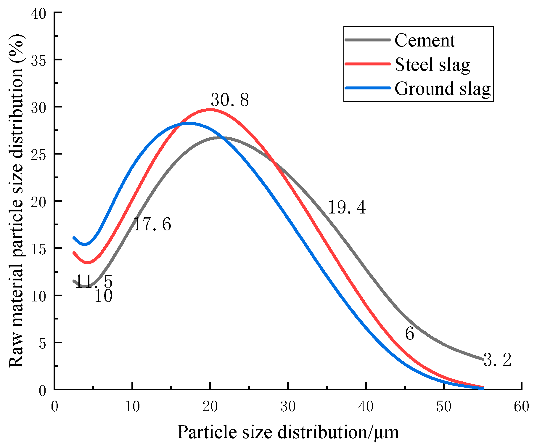
Figure 1 shows the materials used in the experiment, the experimental procedure, and a conceptual diagram of the grouting method. The chemical compositions of the raw materials are given in Table 1. Table 2 lists the particle gradations and compositions of the different sandy soils used in the experiments. Figure 2 shows the raw material particle size distributions. From the analysis results, industrial wastes are inert materials, and it is necessary to improve the pozzolanic activity of industrial wastes by measures, such as alkali activation.

2.2. Preparation of Specimens and Testing Procedures

(1) The baume of the commercially available sodium silicate used in this work was 45 °Bé, with high viscosity and low fluidity. The sodium silicate was diluted to a concentration of 35 °Bé.
(2) The experimental procedure encompassed three primary stages: dry mixing, wet preparation, and casting. Specimens were cast in 70.7 mm cubic moulds and cured under standard conditions (20 ± 2 °C, >95% relative humidity) until they achieved complete solidification and hardening, after which they were demoulded. The compressive strength of the grouting material was then characterised using a WDW-100 testing machine at 3 and 28 days of age, with a constant loading speed of 1 mm/min.
(3) Microscopic inspection test: To analyse the phase composition of the slag-blended samples, X-ray diffraction (XRD) analysis was conducted, employing a scanning range from 5° to 80° with a step size of 0.02° per second. The morphological characteristics and internal microstructure of the samples were examined using scanning electron microscopy (SEM). Furthermore, mercury intrusion porosimetry (MIP) was utilised to determine the porosity of the slag, providing critical data for assessing its impact on the microstructural development of the grouting material.

3. Results and Discussion

It is necessary to select a suitable double-liquid grouting material system, and then to determine the specific components of the grouting materials.

3.1. Selection of the Double-Liquid Grouting Material System

A cement-based grouting material was prepared and tested to study the effect of the content of activated industrial wastes on the compressive strength, fluidity, gel time, and concretion rate of the grouting material. The ratio of the water to binder (W/B) of liquid A is 0.8 and the volume fraction of liquid B accounts for 20% of the liquid volume of liquid A. Table 3 lists the physical and mechanical properties of different double-liquid grouting material systems.
According to the analysis shown in Table 3, the A0 slurry coagulates and hardens in a very short time because C3S and C2S in the slurry rapidly undergo a hydration reaction to generate C-S-H [39], which increases the compressive strength of the A0 mixture. However, owing to the rapid reaction, the fluidity of the slurry is reduced. The compressive strength of the A5 slurry is greater than that of the A6 slurry, indicating that the hydration of SS can strengthen the activation of SL [40,41]. Compared to A0, the A5 slurry has very similar compressive strength, a longer gel time, and better fluidity, indicating that the incorporation of industrial waste slag contributes to the increase in strength and the extension of gel time in the later period. Therefore, a double-liquid grouting material with SS and SL can be considered to replace the traditional cement. Therefore, a large water–binder ratio without cement alkali excitation or an industrial waste slag double-liquid grouting material system is unsuitable for grouting engineering, which requires high early strength [42,43].
Considering that SS has not been widely used in grouting engineering projects, few grouting materials mixed with SS and ground SL have been researched. In this work, considering the SS expansion characteristics and potential gelling properties, SS and SL are used to replace part of the cement as a double-liquid grouting material [44,45].

3.2. Effect of the Sodium Silicate Volume on the Performance of Grouting Materials

Based on the existing experiment, which employs a single-factor controlled variable approach, a single parameter was systematically altered, with the remaining parameters remaining unchanged. To study the influence of the volume of sodium silicate on the physical properties of the grouting material, the fluidity, gel time, and 3 d and 28 d compressive strengths were determined at volume dosages of sodium silicate of 10%, 20%, 30%, 40%, 50%, 60%, 75%, 90%, and 100%.
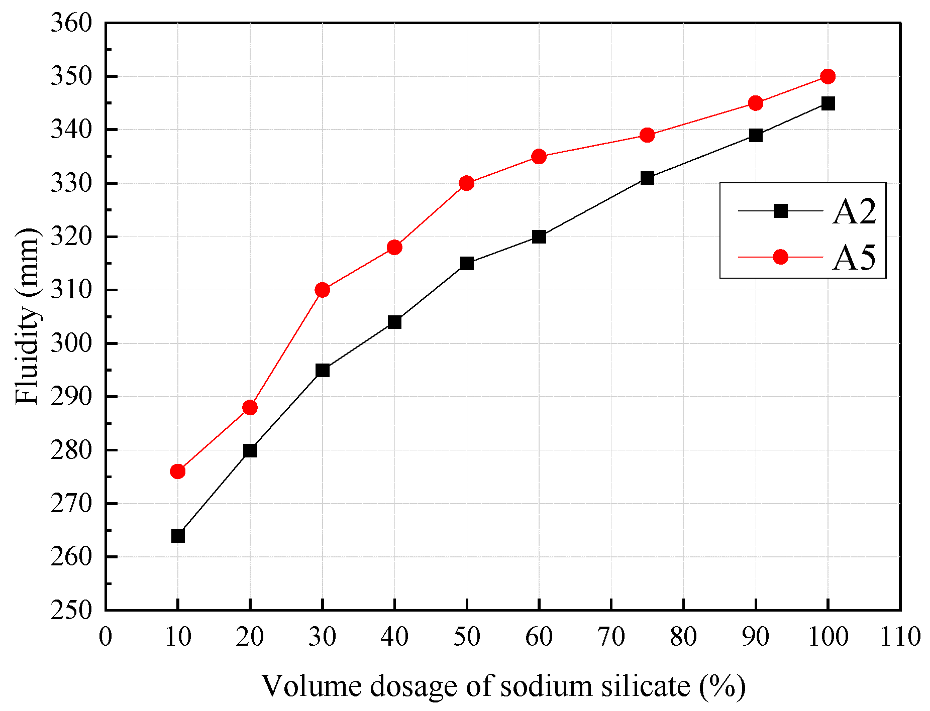
Figure 3 shows the influence of changing the sodium silicate volume dosage on the slurry fluidity when the cement content is 40% and 60%. The fluidity of the slurry increased as the dosage of sodium silicate increased from 10% to 100%. Increasing the sodium silicate volume from 10% to 50% increased the fluidity of A2 and A5 by 19.32% and 19.57%, respectively. When the volume dosage of sodium silicate reaches 50%, the fluidity is greater than 330 mm, which completely meets the needs of grouting engineering.
Figure 4 shows the influence of changing the sodium silicate volume on the gel time when the cement content was 40% and 60%. The gel time of the slurry increased as the dosage of sodium silicate increased from 10% to 100%. Increasing the sodium silicate volume from 10% to 50% increased the fluidity of A2 and A5 by 225.48% and 229.73%, respectively. An increase in the volume of sodium silicate increases the W/B of liquid A, and hydration results in a longer time for the spatial network flocculation structure to connect.
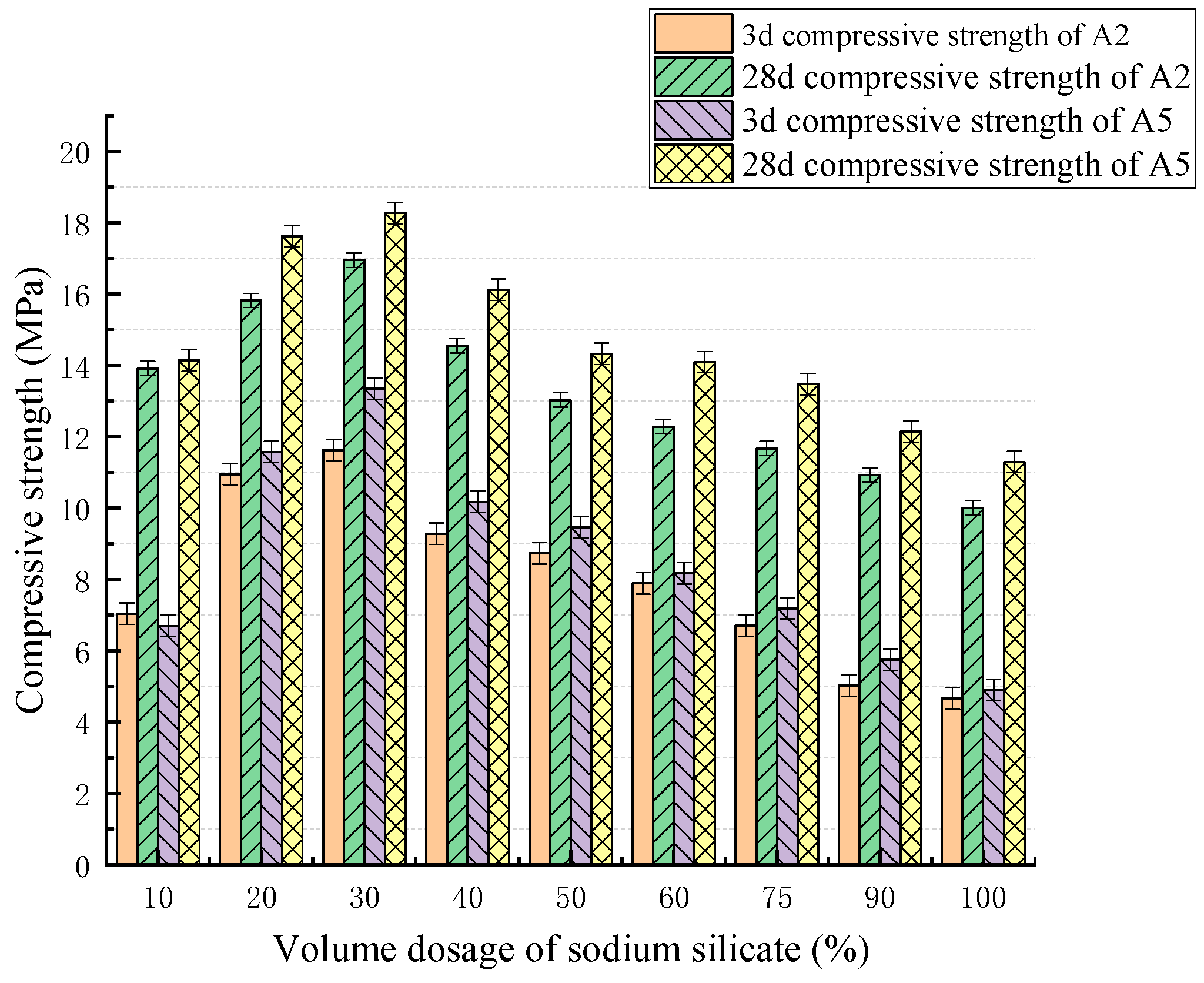
Figure 5 shows the influence of changing the sodium silicate volume on the compressive strength when the cement content is 40% and 60%. When the sodium silicate volume was 30%, the A5 compressive strength at 3 d and 28 d reached 13.35 MPa and 18.27 MPa, respectively. The 28 d compressive strength of A5 is greater than that of A2. When the volume dosage of sodium silicate is 10%, the 3 d compressive strengths of A2 and A5 are reduced by 39.41% and 49.88%, respectively, and the 28 d compressive strengths of A2 and A5 are reduced by 17.94% and 22.71%, respectively, compared with those at a dosage of 30%. When the volume dosage of sodium silicate is 50%, the 3 d compressive strengths of A2 and A5 decrease by 24.87% and 29.14%, respectively, and the 28 d compressive strengths of A2 and A5 decrease by 23.12% and 21.56%, respectively, compared with those at a dosage of 30%.
When the volume of sodium silicate is too high, the sodium silicate hydrolyses and generates a large amount of HnSiO4x− and then generates a silicon gel, and the strength of the silicon gel is very low [46,47]. At the same time, the water in the sodium silicate diluted the slurry, resulting in a decrease in the concrete strength. When the volume of sodium silicate is in the range of 20–40%, the internal structure of the slurry is relatively dense, the concrete strength of the slurry is relatively stable, and the fluidity of the slurry is greater.
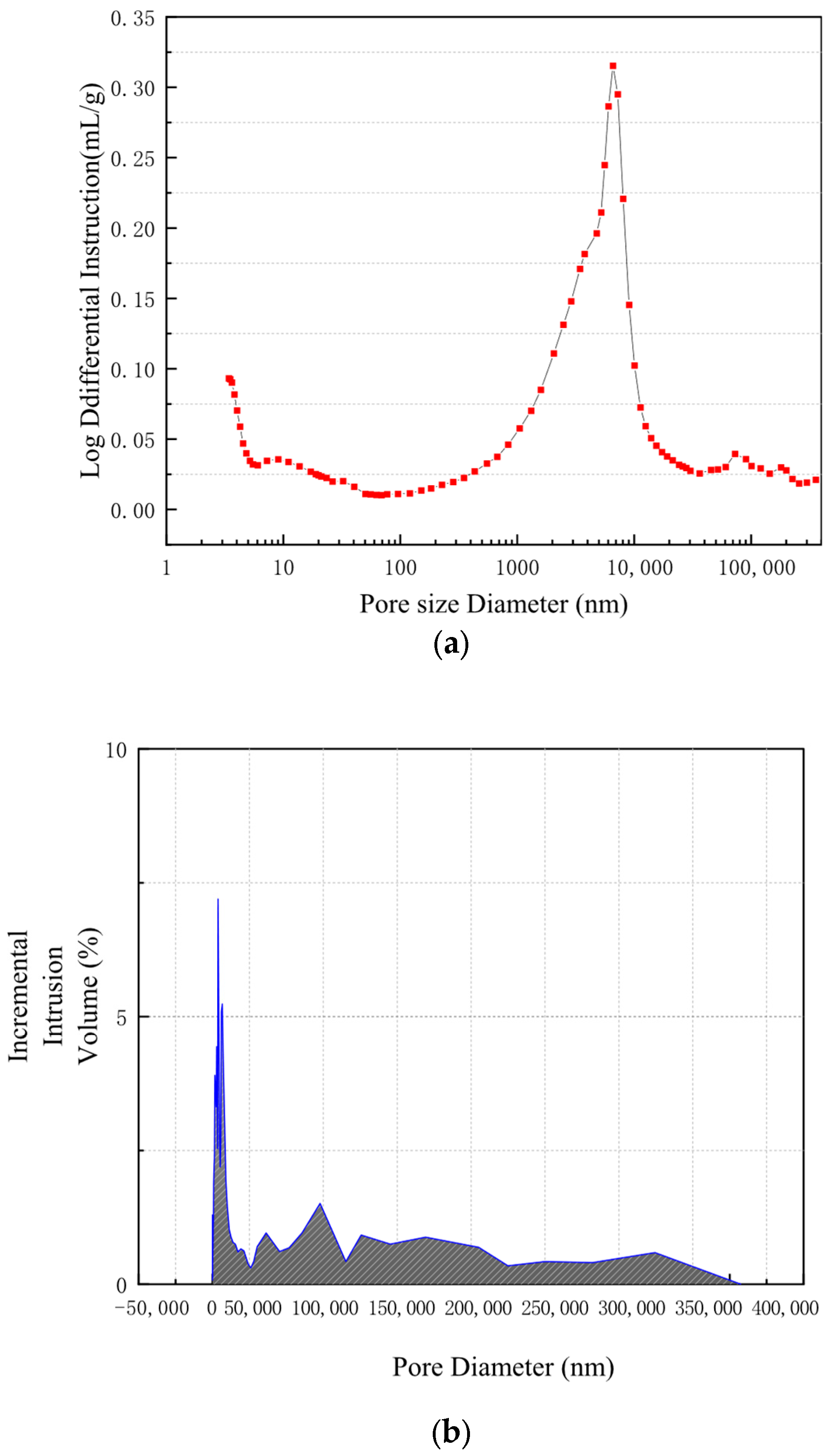
Based on the test results, the pore structure of the A5 grouting material specimen cured for 3 days was analysed using a high-performance automatic mercury porosimeter. The pore structure distribution and incremental intrusion volume of the grouting material test block are shown in Figure 6. As shown in Figure 6a, a 60% substitution of cement with activated industrial slag displaced the pore size distribution curve towards smaller diameters. Figure 6b shows that the percentage of pore volume across different pore size ranges, among which the 0–50,000 nm range accounts for the largest proportion. Collectively, the results indicate that the activated industrial slag positively influences the grouting material’s pore structure. This improvement is attributed to two mechanisms: First, the slag acts as a micro-filler, physically densifying the matrix. Second, its active components participate in hydration, generating additional products that fill internal pores. This synergistic effect results in a more compact microstructure, thereby enhancing the compressive strength.
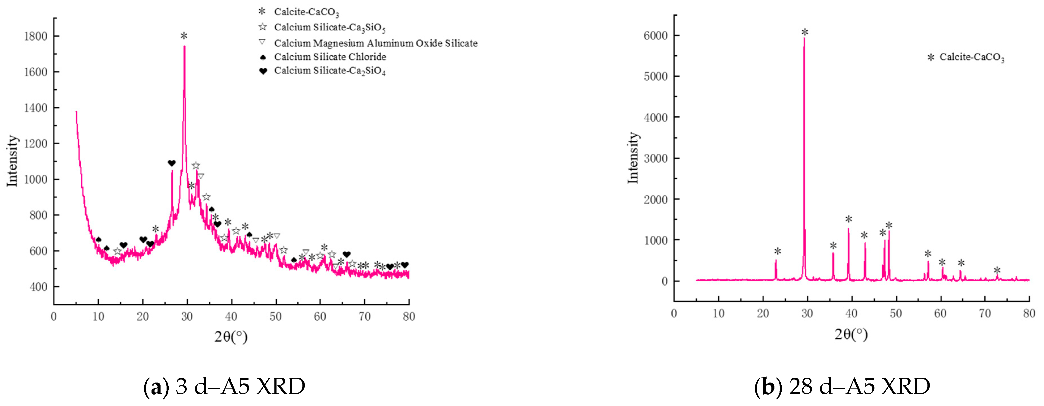
XRD analysis of the A5 grouting material cured for 3 and 28 days (Figure 7) shows that while activated industrial slag does not change the nature of the primary crystalline hydration product (ettringite), it significantly influences the reaction kinetics and phase assemblage. As hydration progresses, the diffraction peaks attributed to the residual C3S and C2S phases in the early-age (3-day) samples progressively weaken (Figure 7a). This attenuation signals the consumption of these clinker minerals through their reaction with water, leading to the formation of C-S-H gel and calcium hydroxide. The consumption of these phases over time, concomitant with the formation of C-S-H and portlandite, underscores the progression of cement hydration. The subsequent reaction of this portlandite with the slag denotes a complementary pozzolanic reaction, forming gel that contributes to microstructural refinement. This series of transformations is manifested in the pronounced temporal changes in the XRD patterns, with the 28-day spectrum being predominantly composed of ettringite as shown in Figure 7b.

3.3. Effects of the Water–Binder Ratio on the Performance of Grouting Materials

To study the influence of the W/B on the properties of grouting materials, the fluidity, gel time, and 3 d and 28 d compressive strengths were evaluated at different W/Bs (0.6, 0.7, 0.8, 0.9, 1.0, 1.2, and 1.5).
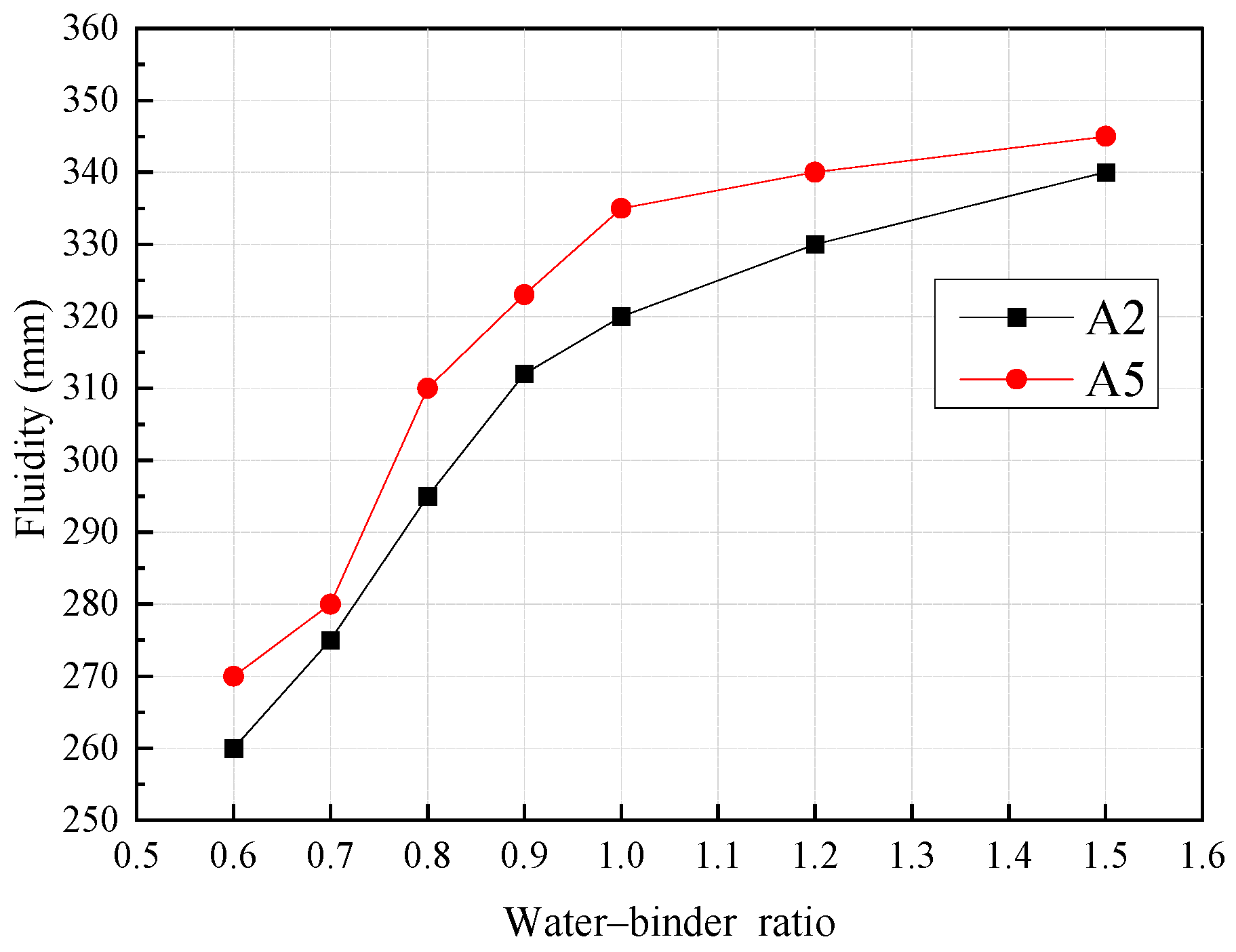
Figure 8 shows the influence of changing the W/B on the fluidity when the cement content is 40% and 60%. Increasing the W/B from 0.6 to 1.0 increases the fluidity of A2 and A5 by 23.08% and 24.07%, respectively. When the amount of water is increased, the flow of water drives the flow of particles, and the distribution of powder particles in grouting materials becomes more uniform.
Figure 9 shows the influence of changing the W/B on the gel time. When the W/B gradually changed from 0.6 to 1.5, the gel time of the slurry gradually increased. When the W/B was 1.0, the gel time of the A2 slurry reached 108 s and the gel time of the A5 slurry reached 126 s, increasing by 500.00% and 447.83%, respectively, compared with those at a W/B of 0.6. The reason for this is that with increasing water consumption, the spacing of particles increases, and the formation of a spatial network structure is slow.
Figure 10 shows the influence of changing the W/B on the compressive strength when the cement content is 40% and 60%. Compared with those at a W/B of 0.8, the 3 d compressive strengths of A2 and A5 at a W/B of 1.0 decreased by 23.75% and 39.85%, respectively, and the 28 d compressive strengths of A2 and A5 at a W/B of 1.0 decreased by 20.83% and 28.24%, respectively. When the W/B exceeds 1.0, the strength of A5 decreases rapidly, indicating that the W/B of grouting material mixed with SS and SL should not be too high. Therefore, the W/B is a crucial factor affecting the strength achieved with the grouting material [48]. The optimal range of the W/B is 0.7–1.0, and the grouting material has high compressive strength and good fluidity in this range.

3.4. Effects of the Cement Content and Industrial Waste Ratio on the Performance of Grouting Materials

The influence of the cement content and industrial waste slag proportion on the properties of the grouting material was studied by evaluating the fluidity, gel time, and 3 d and 28 d compressive strengths of the grouting material at different cement contents and industrial waste slag proportions. The cement contents were 20%, 30%, 40%, 50%, and 60%, and the SS:SL ratios were 5:5, 4:6, 3:7, and 2:8. In the study of the cement content and specific proportions of industrial waste slag, the relationships among cement, SS, and SL were determined, providing support for the wide application of iron and steel slag double-mixing powder in grouting engineering.
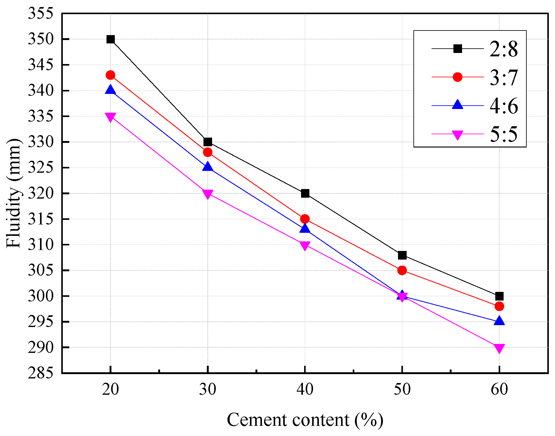
Figure 11 shows the influence of changing the cement content and industrial waste slag proportion on fluidity. The setting kinetics of the slurry are directly influenced by the proportion of industrial waste. A fluidity of 350 mm is achieved with a 20% cement fraction. The key chemical components, including C2S, C3S, and free-CaO from the cementitious materials, readily undergo a pozzolanic reaction in the sodium silicate-activated alkaline medium. This process involves a rapid reaction between calcium ions and silicate anions, resulting in the immediate formation of C-S-H gel. Consequently, the slurry experiences a significant viscosity increase, a decline in flowability, and a markedly reduced gel time.
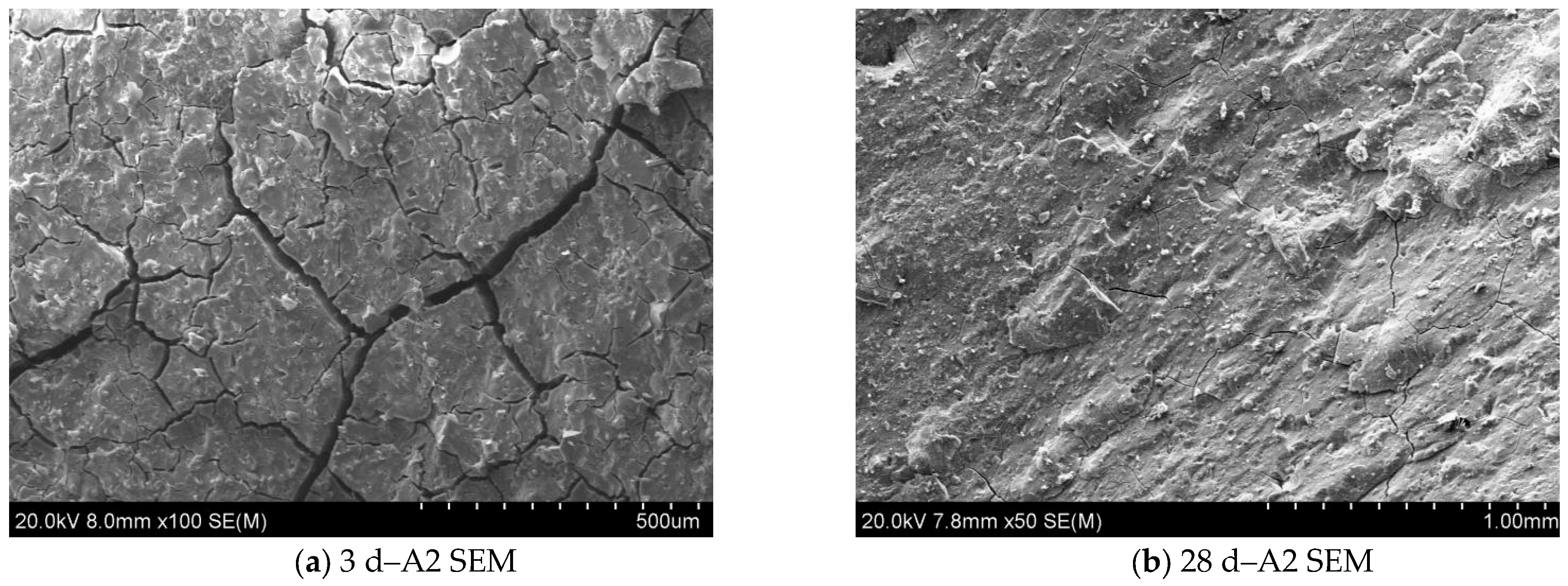
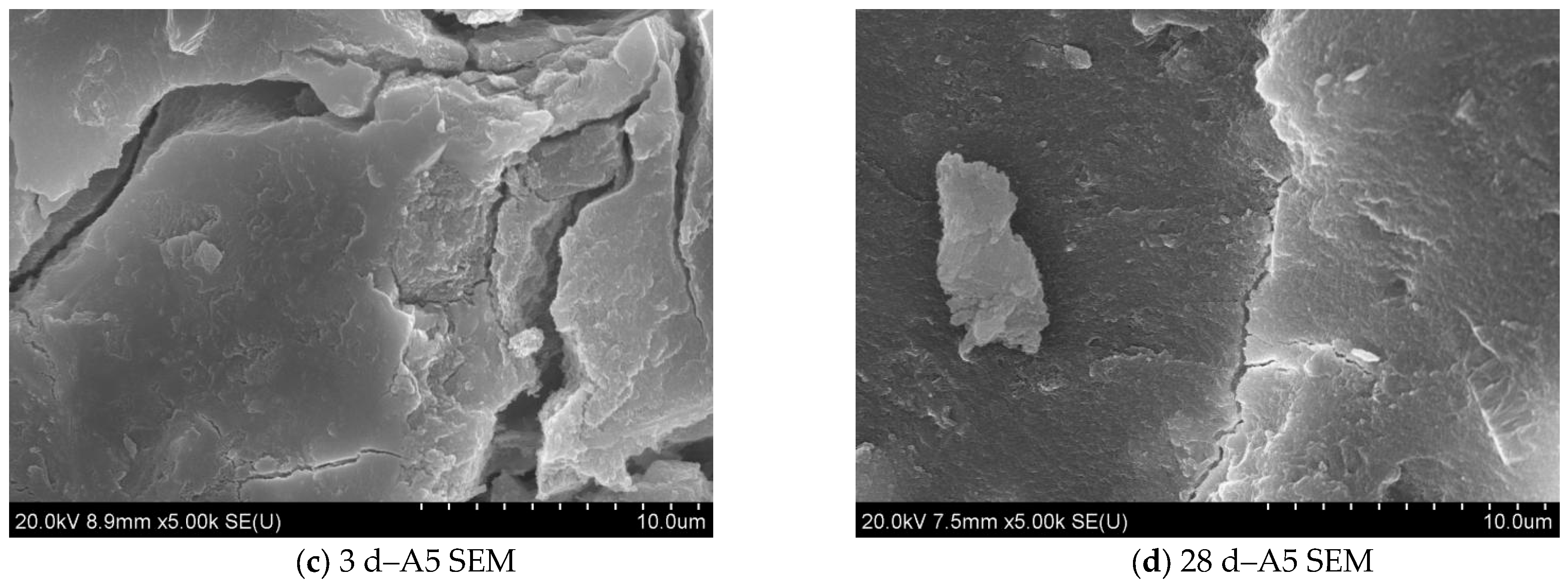
Figure 12 shows that the microstructural evolution of the cement-based grouting material, incorporating activated industrial slag as a cement replacement, at 3 and 28 days of curing. The C-S-H gel is constituted by a multitude of fine particles that coalesce, leading to the development of a continuous three-dimensional network with an interlocking morphology. This gel phase serves as a binding agent, connecting the dispersed unreacted particles and randomly distributed ettringite, thereby consolidating the microstructure and resulting in enhanced integrity and compactness.
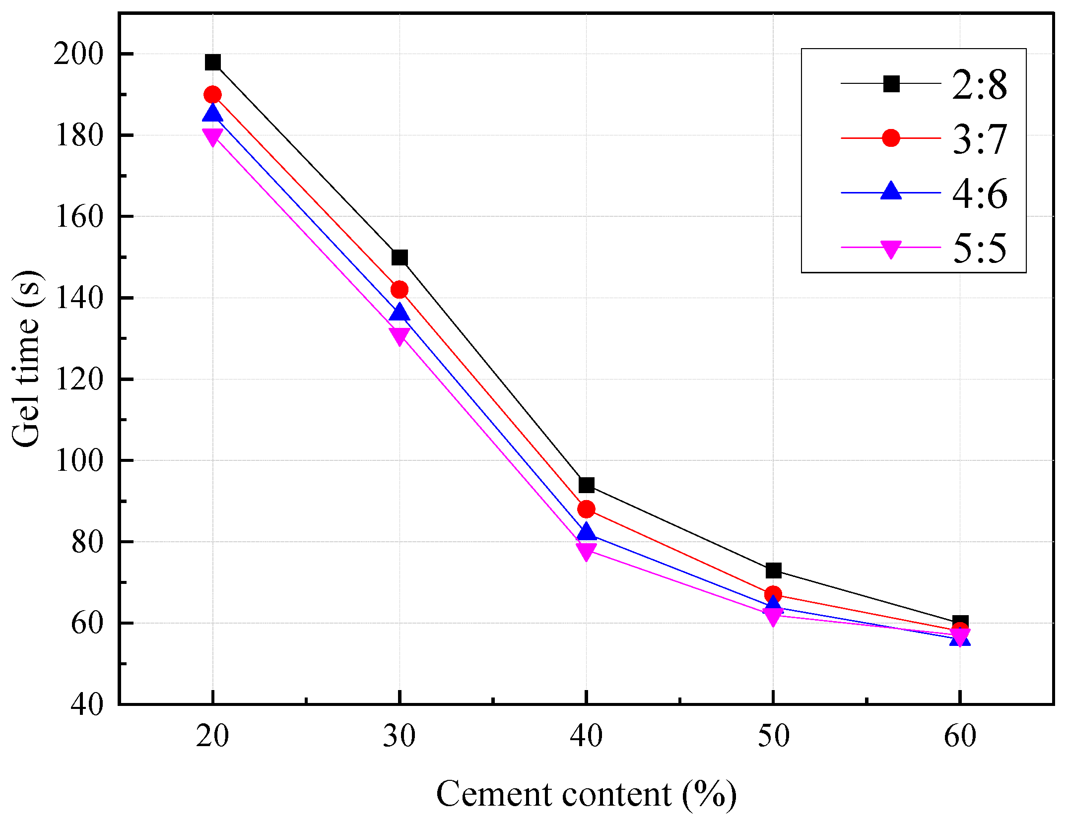
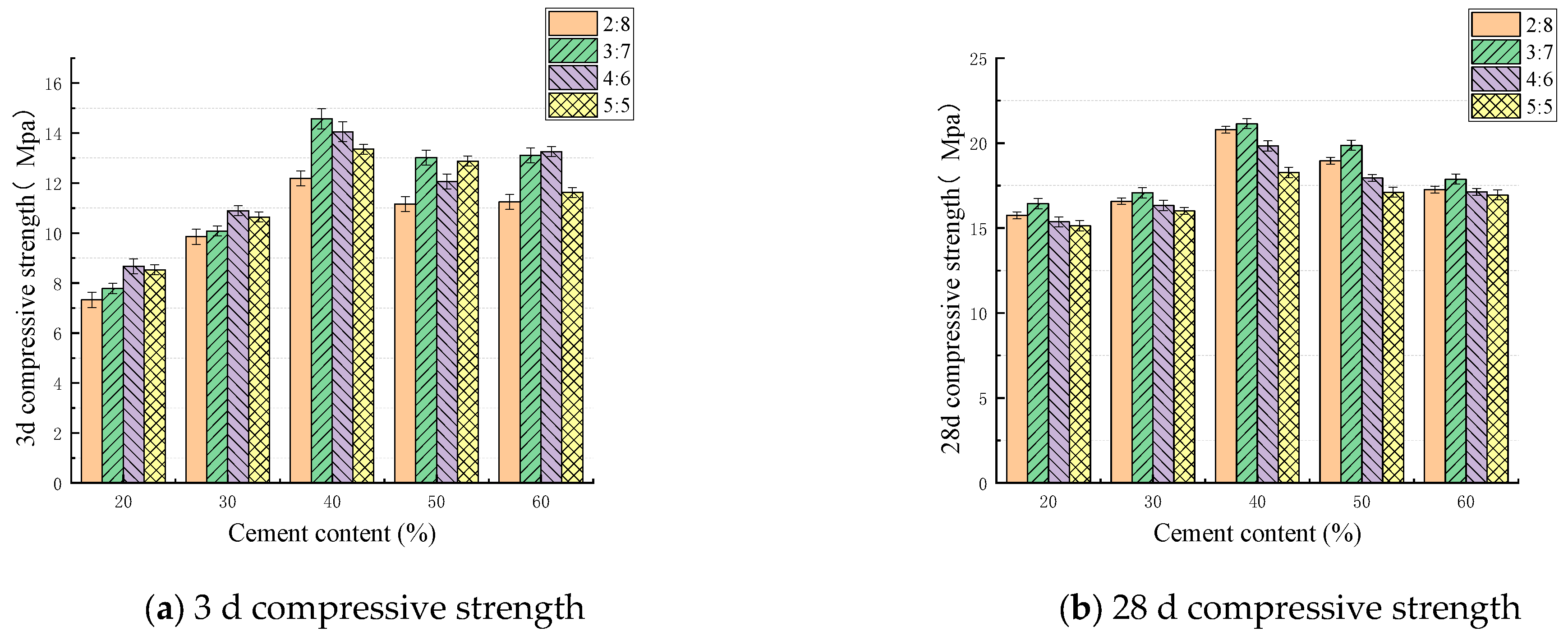
Figure 13 and Figure 14 shows the influences of changing the cement content and industrial waste slag proportion on the gel time and compressive strength. The 28 d compressive strength reaches a maximum when the SS:SL ratio is 3:7. Unlike SS, SL can rapidly release Ca2+ to form a gel. However, in the later period, owing to the action of OH, Si–O–Si, Al–O–Al, and Si–O–Al bonds in SL, Ca2+, [AlO4]5+, and [SiO4]4+ dissolve to form new polymers [49,50]. The combination with Na+ to form a durable zeolite material increases the compressive strength [51,52].

3.5. Effects of Admixtures on the Performance of Grouting Materials

Through a large number of experiments in the early stage, three retarders were finally selected. Figure 15 shows the influence of the dosages of the three retarding agents, disodium hydrogen phosphate (Na2HPO4), sodium potassium tartrate (C4H4KNaO6), and sodium polyphosphate (NaO18P6), on the gel time. Na2HPO4 has the most considerable ability to improve the gel time of the grouting material, prolonging it by more than five times, indicating that Na2HPO4 can regulate the gel time of the grouting material. When the dosage of Na2HPO4 was 2%, the gel time of the slurry was the longest. The mechanism involves the hydrolysis of Na2HPO4 to generate H2PO4, whereas H2PO4 reacts with Ca2+ in the slurry to generate insoluble calcium phosphate, which adsorbs on the surface of mineral particles, hinders the continuous hydration of C3S and C2S in cement and SS, and slows the formation of C-S-H gel.
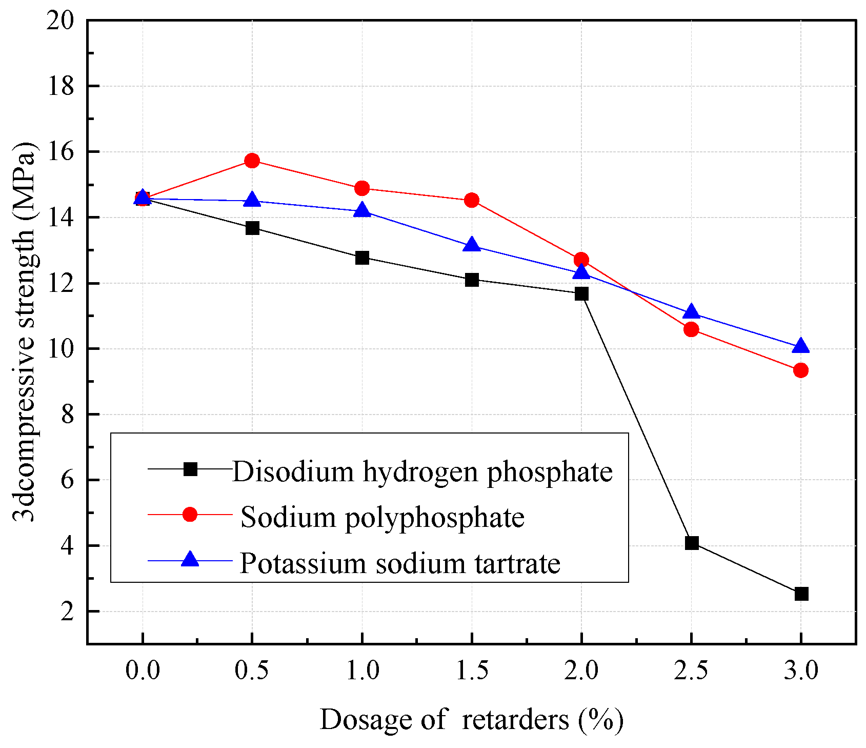
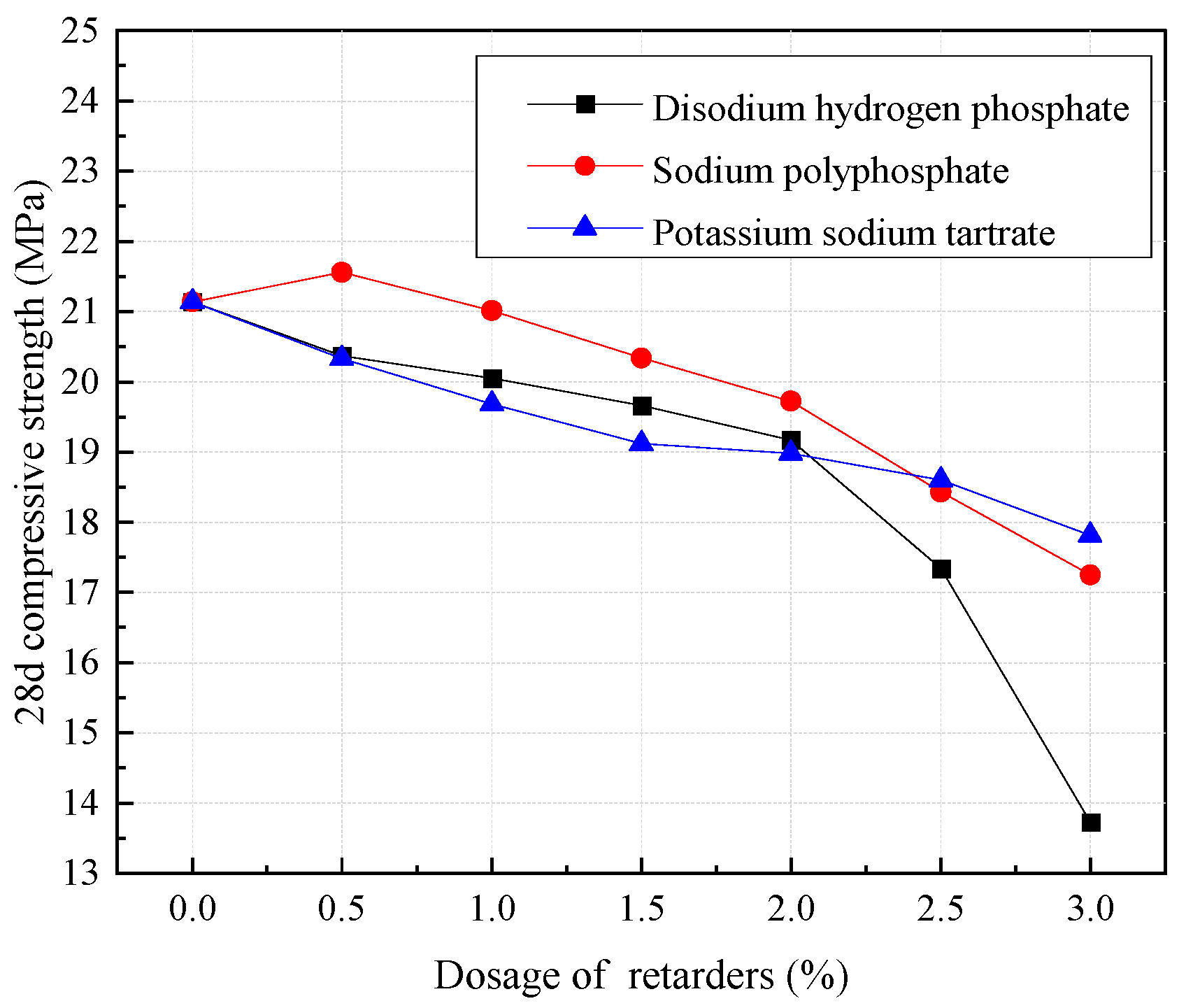
Figure 16 and Figure 17 show the effect of changing the dosage of the three retarding agents on the compressive strength. The compressive strength of concrete mixed with Na2HPO4, NaO18P6, and C4H4KNaO6 decreases with increasing retarding agent dosage. When the dosage of Na2HPO4 is greater than 2%, the 3 d and 28 d compressive strengths of the concrete decrease extremely rapidly.

4. Engineering Applications

4.1. Grouting Scheme Design

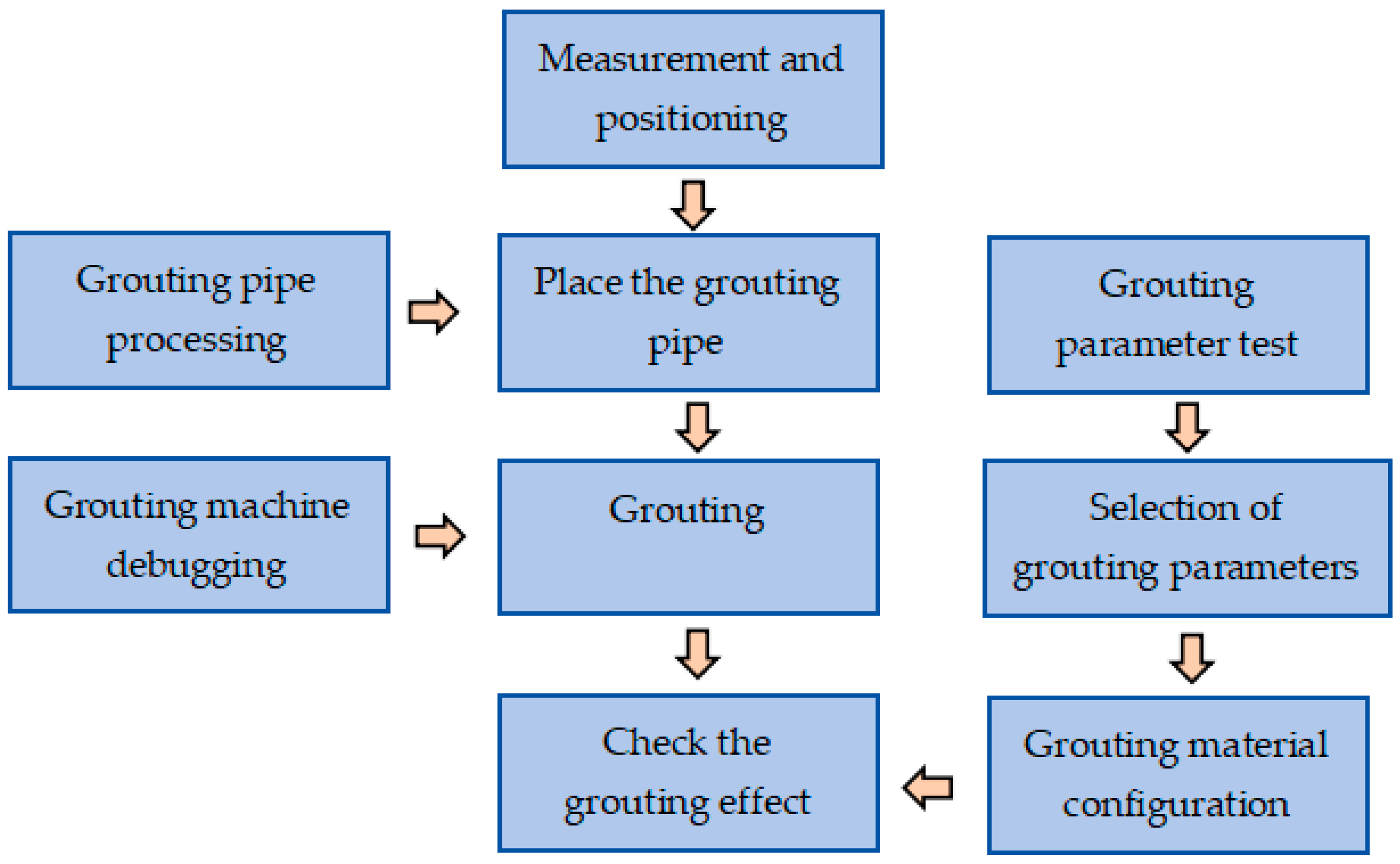
Severe water gushing can be found at some tunnel excavation sites. Grouting is an effective and direct solution. Based on the current cost prices in the building materials market, the price of PO 42.5 ordinary Portland cement is RMB 360 per ton, the price of steel slag is RMB 200 per ton, the price of ground slag is RMB 200 per ton, and the price of sodium silicate is RMB 1000 per ton. The double-liquid grouting material that incorporates both steel slag and ground slag saves a significant amount of cement, which has substantial economic significance. Figure 18 shows the entire grouting process at the construction project site. Through continuous experiments at the engineering site, the construction parameters for grouting engineering using new grouting material are shown in Table 4. Based on the grouting mechanism and the properties of green grouting materials, parameters such as grouting pressure and grouting range will be determined, along with the evaluation of grouting effectiveness. This study will provide targeted guidance for grouting projects in sandy layers, reducing the blind spots in construction. This study will be of significant importance in reducing the overall costs of grouting materials and enhancing the safety of underground engineering in sandy layers.

4.2. Effect of the Water Content of Sandy Soil on the Strength of Sandy Soil Consolidation

In actual grouting engineering, according to the requirements of reinforcement and water plugging, determining the strength of the consolidation is the key to the success of the project. To analyse the influence of the soil moisture content on the strength of consolidated sand, compressive strength tests were performed on six groups of samples with moisture contents of 0%, 3%, 6%, 9%, 12%, and 15%.
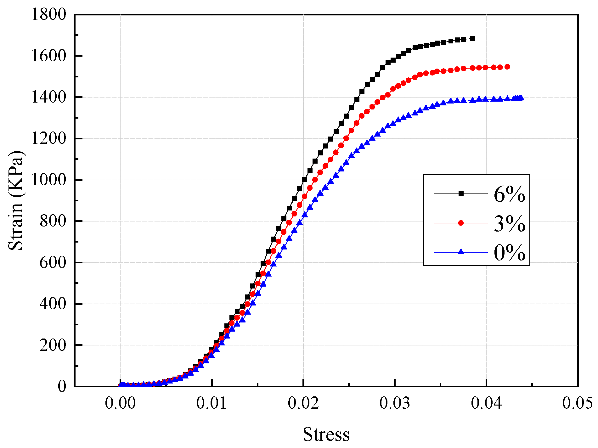
Figure 19 shows the variation in compressive strength with changing moisture content of the sandy soil. Free water causes the slurry to coagulate and harden to produce many tiny voids so that the overall compactness decreases [53,54]. If the actual grouting pressure is low, residual water will occupy the pores between the sand particles. The stresses and strains of samples with different moisture contents are shown in Figure 20.

4.3. Effect of the Grain Gradation of Sand in Sandy Soil on the Strength of Sandy Soil Consolidation

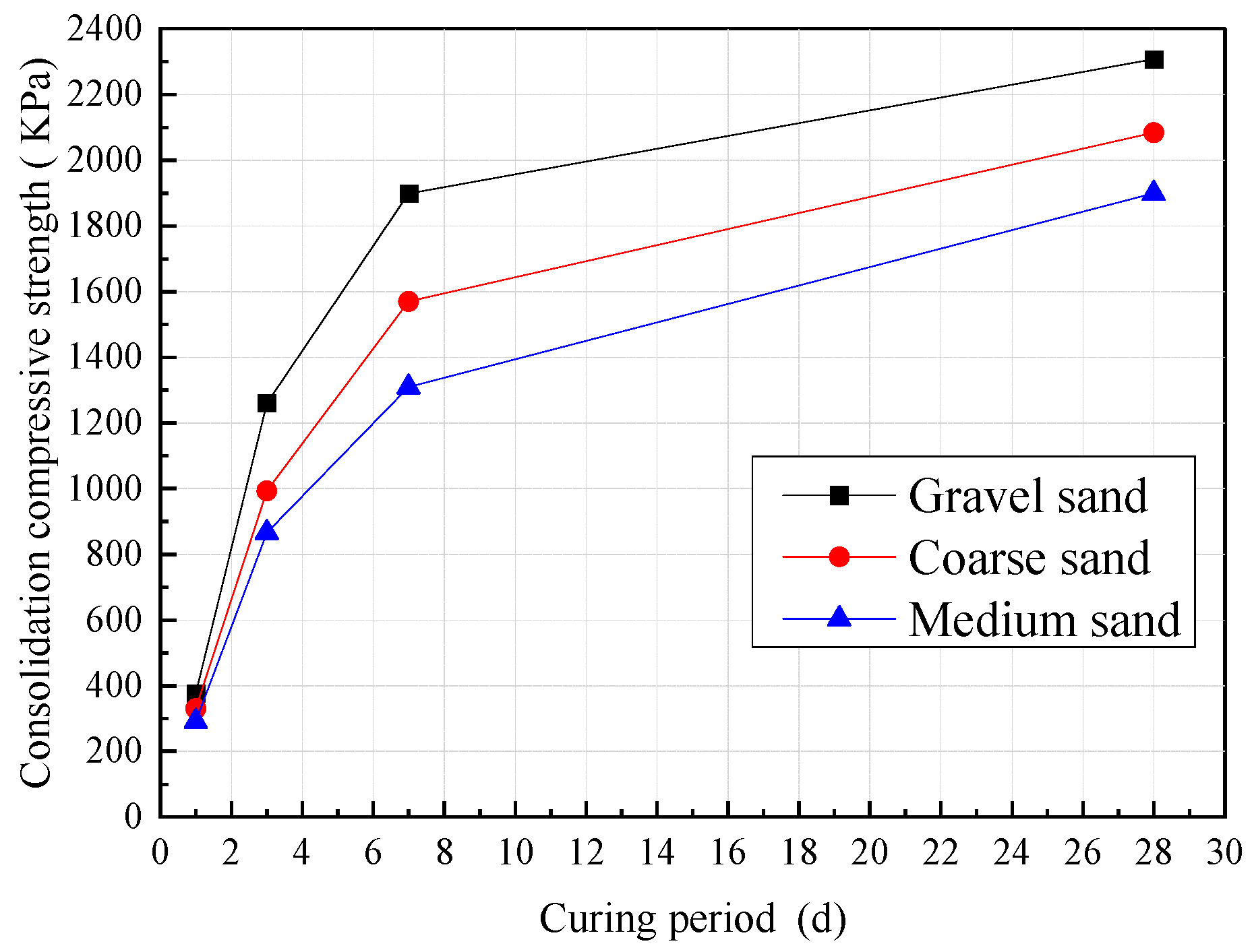
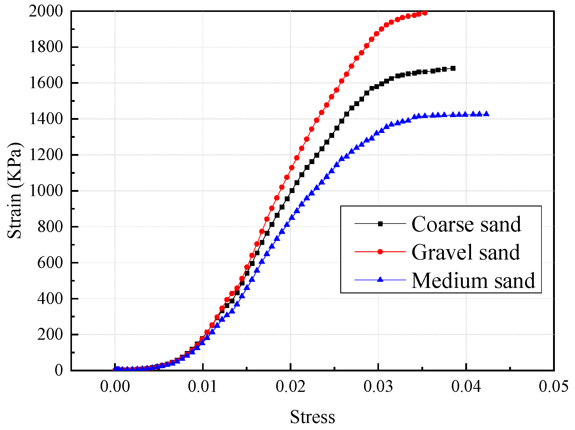
To analyse the influence of different types of sand on the strength of consolidation, three kinds of sand (gravel sand, coarse sand, and medium sand) from the excavation of the Shenyang tunnel project were selected to study the influence law of the compressive strength of consolidation. Figure 21 shows the variation in the compressive strength of consolidation with changes in the particle distribution of sand under the condition of a cement–sodium silicate double-liquid grouting material mixed with SS and SL. Figure 21 shows that gravelly sand has the highest consolidation strength. New grouting material is more suitable for sandy strata above medium sand. The stresses and strains of the samples with different particle sizes are shown in Figure 22.

4.4. Effect of Slurry Dosage on the Strength of Sandy Soil Consolidation

Owing to the limited diffusion distance of the grouting material in the stratum, with increasing slurry viscosity and the continuous attenuation of the grouting pressure, the amount of slurry at a distance from the grouting pipe is less, so that the stratum at a distance from the grouting pipe cannot be further strengthened. To analyse the influence of the grouting material dosage on the strength of consolidation, five slurry dosages of 10%, 20%, 30%, 40%, and 50% were tested.
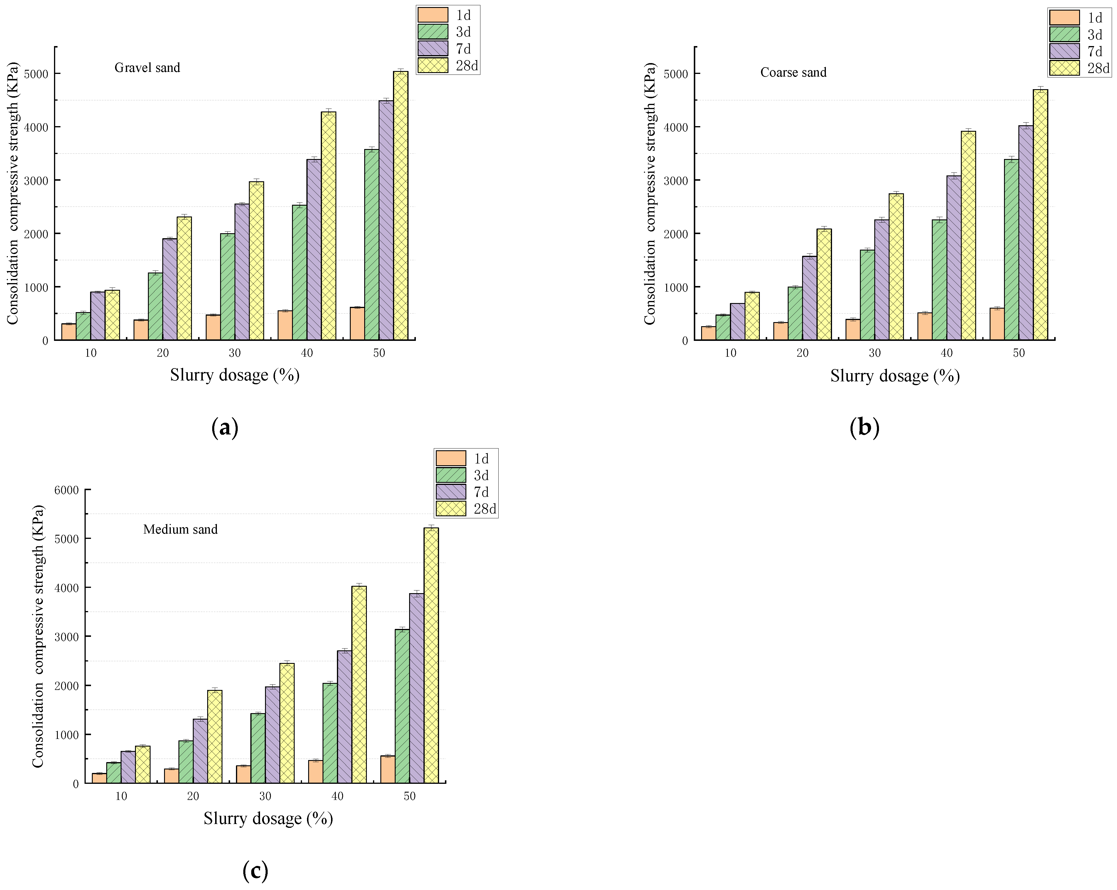
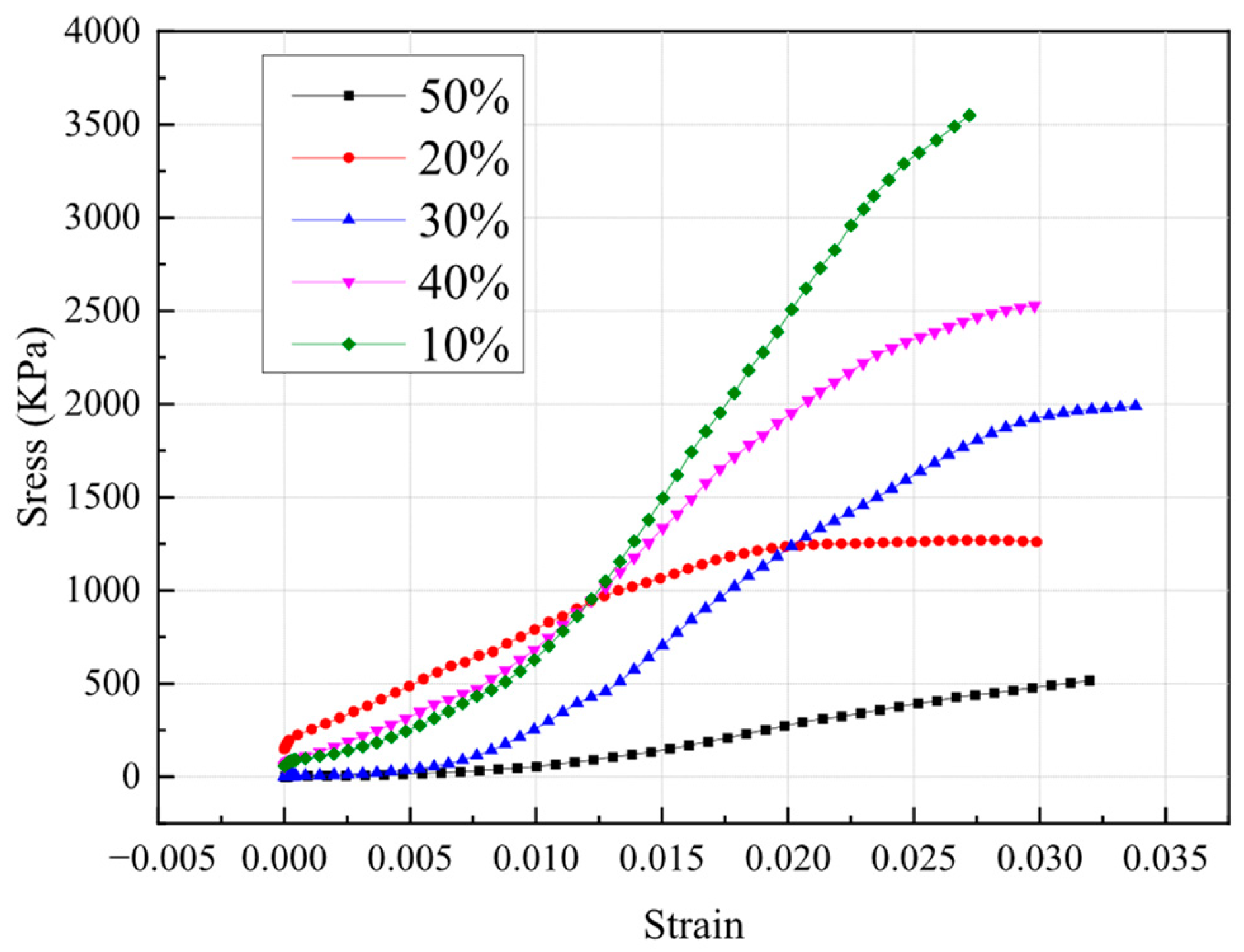
Figure 23 shows the effect of the slurry dosage on the 1 d, 3 d, 7 d and 28 d compressive strengths. With increasing slurry dosage, the reaction of the C-S-H gel-type zeolite material increased, and the reactions of the products, not only the soil filling effect but also the soil particle cementing effect, gradually decreased the soil porosity and improved the cohesive force. The stresses and strains of the samples subjected to different slurry dosages are shown in Figure 24.
However, it should be noted that there are certain discrepancies between laboratory tests and in situ test results. Therefore, to more accurately evaluate the permeability and durability of grouted sand in the future, two reliable methods, automated weighing scales [55] and computer vision techniques [56], are planned for measuring absorption.

5. Conclusions

The mechanism of alkali-activated cementitious materials by selecting steel slag and ground slag to replace cement in double-liquid grouting materials has been proposed in this study. Based on the aforementioned experiments, the following conclusions are drawn:
(1)
When the volume of sodium silicate is in the range of 20–40%, the internal structure of the slurry is compact, and the strength of the slurry is high and relatively stable. When the W/B is in the range of 0.7–1.0, the compressive strength and flow performance are better. When the cement content is 40%, the W/B is 0.8, the sodium silicate volume dosage is 30%, and the SS:SL ratio is 3:7, the 3 d compressive strength of the slurry reaches 14.57 MPa and the 28 d compressive strength reaches 21.14 MPa.
(2)
Compared with NaO18P6 and C4H4KNaO6, Na2HPO4 has the best retarding effect. When the dosage of disodium phosphate is less than 2%, the gel time is prolonged with increasing disodium phosphate dosage, and the rate of decrease in the compressive strength is only slightly affected.
(3)
Cement sodium silicate double-liquid grouting material mixed with SS and SL has the best reinforcing effect on gravelly sand, and this system is more suitable for strata above medium sand.

Author Contributions

H.X. and G.X. conceived and designed the experiments; H.X. performed the experiments; H.X. and Q.B. analysed the data; H.X. and Q.B. wrote the paper. All authors have read and agreed to the published version of the manuscript.

Funding

This research was funded by the Three Vertical Scientific Research Support Program for Fundamental Cultivation Projects, ZRCPY202328, and the Heilongjiang Province Ecological Environment Protection Research Project, HST2024GF009.

Data Availability Statement

Data are contained within the article.

Acknowledgments

The authors would like to acknowledge all project partners of the applications presented and discussed within this publication, especially the School of Resources and Civil Engineering, Northeastern University (Wen Zhao, Shengang Li) and the School of Urban Rail Transportation, Soochow University (Cheng Cheng).

Conflicts of Interest

The authors declare no conflicts of interest.

References

  1. Jeng, F.S.; Weng, M.C.; Huang, T.H.; Lin, M.L. Deformational characteristics of weak sandstone and impact to tunnel deformation. Tunn. Undergr. Space Technol. 2002, 17, 263–274. [Google Scholar] [CrossRef]
  2. Shahrour, I.; Khoshnoudian, F.; Sadek, M.; Mroueh, H. Elastoplastic analysis of the seismic response of tunnels in soft soils. Tunn. Undergr. Space Technol. 2010, 25, 478–482. [Google Scholar] [CrossRef]
  3. Zhang, C.; Fu, J.; Yang, J.; Ou, X.; Ye, X.; Zhang, Y. Formulation and performance of grouting materials for underwater shield tunnel construction in karst ground. Constr. Build. Mater. 2018, 187, 327–338. [Google Scholar] [CrossRef]
  4. Sha, F.; Lin, C.; Li, Z.; Liu, R. Reinforcement simulation of water-rich and broken rock with Portland cement-based grout. Constr. Build. Mater. 2019, 221, 292–300. [Google Scholar] [CrossRef]
  5. Mollamahmutoğlu, M.; Yılmaz, Y.; Kutlu, I. Grouting performance of microfine cement and silica fume mix into sands. J. ASTM Int. 2007, 4, JAI100462. [Google Scholar] [CrossRef]
  6. Li, S.; Sha, F.; Liu, R.; Li, W.; Li, Z.; Wang, G. Properties of cement-based grouts with high amounts of ground granulated blast-furnace slag and fly ash. J. Mater. Civ. Eng. 2017, 29, 04017219. [Google Scholar] [CrossRef]
  7. Saridemir, M. Effect of silica fume and ground pumice on compressive strength and modulus of elasticity of high strength concrete. Constr. Build. Mater. 2013, 49, 484–489. [Google Scholar] [CrossRef]
  8. Zeng, Q.; Li, K.; Fen, T.; Dangla, P. Determination of cement hydration and pozzolanic reaction extents for fly-ash cement pastes. Constr. Build. Mater. 2012, 27, 560–569. [Google Scholar] [CrossRef]
  9. Alnahhal, A.M.; Alengaram, U.J.; Yusoff, S.; Singh, R.; Radwan, M.K.; Deboucha, W. Synthesis of sustainable lightweight foamed concrete using palm oil fuel ash as a cement replacement material. J. Build. Eng. 2021, 35, 102047. [Google Scholar] [CrossRef]
  10. Asdrubali, F.; D’Alessandro, F.; Schiavoni, S. A review of unconventional sustainable building insulation materials. Sustain. Mater. Technol. 2015, 4, 1–17. [Google Scholar] [CrossRef]
  11. Raut, A.N.; Gomez, C.P. Utilization of glass powder and oil palm fibers to develop thermally efficient blocks. Arab. J. Sci. Eng. 2020, 45, 3959–3972. [Google Scholar] [CrossRef]
  12. Puertas, F.; Santos, H.; Palacios, M.; Martínez-Ramírez, S. Polycarboxylate superplasticizer admixtures: Effect on hydration, microstructure and rheological behaviour in cement pastes. Adv. Cem. Res. 2005, 17, 77–89. [Google Scholar] [CrossRef]
  13. Messaoud, M.; Glaoui, B.; Abdelkhalek, O. The effect of adding steel fibers and graphite on mechanical and electrical behaviors of asphalt concrete. Civ. Eng. J. 2022, 8, 348–361. [Google Scholar] [CrossRef]
  14. Shi, Z.; Wang, Q.; Xu, L. Experimental study of cement alkali-resistant glass fiber (C-ARGF) grouting material. Materials 2020, 13, 605. [Google Scholar] [CrossRef] [PubMed]
  15. Zhang, C.; Yang, J.-S.; Fu, J.-Y.; Ou, X.-F.; Xie, Y.-P.; Dai, Y.; Lei, J.-S. A new clay-cement composite grouting material for tunnelling in underwater karst area. J. Cent. South Univ. 2019, 26, 1863–1873. [Google Scholar] [CrossRef]
  16. Gao, Y.; Li, Z.; Zhang, J.; Zhang, Q.; Wang, Y. Synergistic use of industrial solid wastes to prepare belite-rich sulphoaluminate cement and its feasibility use in repairing materials. Constr. Build. Mater. 2020, 264, 120201. [Google Scholar] [CrossRef]
  17. Ghalehnovi, M.; Roshan, N.; Hakak, E.; Shamsabadi, E.A.; de Brito, J. Effect of red mud (bauxite residue) as cement replacement on the properties of self-compacting concrete incorporating various fillers. J. Clean. Prod. 2019, 240, 118213. [Google Scholar] [CrossRef]
  18. Mashifana, T.; Sithole, T. Clean production of sustainable backfill material from waste gold tailings and slag. J. Clean. Prod. 2021, 308, 127357. [Google Scholar] [CrossRef]
  19. Mollamahmutoğlu, M.; Avci, E. Ultrafine Portland cement grouting performance with or without additives. KSCE J. Civ. Eng. 2015, 19, 2041–2050. [Google Scholar] [CrossRef]
  20. Lin, C.; Dai, W.; Li, Z.; Wang, Y. Study on the inorganic synthesis from recycled cement and solid waste gypsum system: Application in grouting materials. Constr. Build. Mater. 2020, 251, 118930. [Google Scholar] [CrossRef]
  21. Guo, S.; Zhang, J.; Li, M.; Zhou, N.; Song, W.; Wang, Z.; Qi, S. A preliminary study of solid-waste coal gangue based biomineralization as eco-friendly underground backfill material: Material preparation and macro-micro analyses. Sci. Total Environ. 2021, 770, 145241. [Google Scholar] [CrossRef] [PubMed]
  22. Fang, F.; Wang, Z.; Zhang, F.; Li, D.; Jia, Z.; Wang, Z.; Jiang, T.; Lan, W. Experimental study of alkali-excited steel slag–granulated blast-furnace slag–cement-based grouting material based on response surface methodology. Buildings 2024, 14, 3841. [Google Scholar] [CrossRef]
  23. Li, M.; Huang, G.; Cui, Y.; Wang, B.; Chang, B.; Yin, Q.; Zhang, S.; Wang, Q.; Feng, J.; Ge, M. Coagulation mechanism and compressive strength characteristics analysis of high-strength alkali-activated slag grouting material. Polymers 2022, 14, 3980. [Google Scholar] [CrossRef] [PubMed]
  24. Cai, X.; Cao, Z.; Sun, J.; Wang, H.; Wu, S. Influence of steel slag on properties of cement-based materials. Buildings 2024, 14, 2985. [Google Scholar] [CrossRef]
  25. Li, N.; Shi, C.; Wang, Q.; Zhang, Z.; Ou, Z. Composition design and performance of alkali-activated cements. Mater. Struct. 2017, 50, 178. [Google Scholar] [CrossRef]
  26. Xu, R.; Kong, F.; Yang, R.; Wang, H.; Hong, T. Influences of silicate modulus and alkali content on macroscopic properties and microstructure of alkali-activated blast furnace slag-copper slag. Constr. Build. Mater. 2024, 442, 137622. [Google Scholar] [CrossRef]
  27. Yao, G.; Liu, Q.; Wang, J.; Wu, P.; Lyu, X. Effect of mechanical grinding on pozzolanic activity and hydration properties of siliceous gold ore tailings. J. Clean. Prod. 2019, 217, 12–21. [Google Scholar] [CrossRef]
  28. Nath, P.; Sarker, P.K. Effect of GGBFS on setting. 2014. workability and early strength properties of fly ash geopolymer concrete cured in ambient condition. Constr. Build. Mater. 2014, 66, 163–171. [Google Scholar] [CrossRef]
  29. Yao, G.; Wang, Q.; Su, Y.; Wang, J.; Qiu, J.; Lyu, X. Mechanical activation as an innovative approach for the preparation of pozzolan from iron ore tailings. Miner. Eng. 2020, 145, 106068. [Google Scholar] [CrossRef]
  30. Wang, Q.; Wang, D.; Zhuang, S. The soundness of steel slag with different free CaO and MgO contents. Constr. Build. Mater. 2017, 151, 138–146. [Google Scholar] [CrossRef]
  31. Davidovits, J. Geopolymers. J. Therm. Anal. Calorim. 1991, 37, 1633–1656. [Google Scholar] [CrossRef]
  32. Niklioć, I.; Marković, S.; Janković–Častvan, I.; Radmilović, V.V.; Karanović, L.; Babić, B.; Radmilović, V.R. Modification of mechanical and thermal properties of fly ash-based geopolymer by the incorporation of steel slag. Mater. Lett. 2016, 176, 301–305. [Google Scholar] [CrossRef]
  33. Huang, X.; Huang, T.; Li, S.; Muhammad, F.; Xu, G.; Zhao, Z.; Yu, L.; Yan, Y.; Li, D.; Jiao, B. Immobilization of chromite ore processing residue with alkali-activated blast furnace slag-based geopolymer. Ceram. Int. 2016, 42, 9538–9549. [Google Scholar] [CrossRef]
  34. Zhang, Y.; Yang, D.; Wang, Q. Performance study of alkali-activated phosphate slag-granulated blast furnace slag composites: Effect of the granulated blast furnace slag content. Arch. Civ. Mech. Eng. 2023, 23, 181. [Google Scholar] [CrossRef]
  35. Singh, S.; Jyoti; Vashistha, P. Development of newer composite cement through mechano-chemical activation of steel slag. Constr. Build. Mater. 2021, 268, 121147. [Google Scholar] [CrossRef]
  36. Zheng, L.; Wang, W.; Shi, Y. The effects of alkaline dosage and Si/Al ratio on the immobilization of heavy metals in municipal solid waste incineration fly ash-based geopolymer. Chemosphere 2010, 79, 665–671. [Google Scholar] [CrossRef]
  37. GB 175-2023; Common Portland Cement. Standardization Administration of the People’s Republic of China: Beijing, China, 2023.
  38. GB/T 1596-2017; Fly Ash Used for Cement and Concrete. Standardization Administration of the People’s Republic of China: Beijing, China, 2017.
  39. Detwiler, R.; Bhatty, J.; Bhattacharja, S. Supplementary cementing materials for use in blended cements. In Research and Development Bulletin RD112; Portland Cement Association: Skokie, IL, USA, 1996. [Google Scholar]
  40. Liu, C.; Shui, Z.; Gao, X.; Ma, S. Performance Evaluation of Alkali-Activated Coal Gangue-Blast Furnace Slag Composite. Bull. Chin. Ceram. Soc. 2020, 39, 2877–2884. [Google Scholar] [CrossRef]
  41. Song, S.; Sohn, D.; Jennings, H.M.; Mason, T.O. Hydration of alkali-activated ground granulated blast furnace slag. J. Mater. Sci. 2000, 35, 249–257. [Google Scholar] [CrossRef]
  42. Hossain, M.M.; Karim, M.R.; Elahi, M.M.A.; Islam, M.N.; Zain, M.F.M. Long-term durability properties of alkali-activated binders containing slag, fly ash, palm oil fuel ash and rice husk ash. Constr. Build. Mater. 2020, 251, 119094. [Google Scholar] [CrossRef]
  43. Santamaría, A.; Orbe, A.; José, J.S.; González, J. A study on the durability of structural concrete incorporating electric steelmaking slags. Constr. Build. Mater. 2018, 161, 94–111. [Google Scholar] [CrossRef]
  44. Jiang, L.; Dong, C.-L.; Wang, S.-Y. Reducing volume expansion of steel slag by using a surface hydrophobic waterproof structure. J. Mater. Civ. Eng. 2020, 32, 04020303. [Google Scholar] [CrossRef]
  45. Sha, F.; Li, S.; Liu, R.; Li, Z.; Zhang, Q. Effects of fineness on viscoelasticity of microfine cement-based grouts with fly ash, silica fume and superplasticizer. Adv. Cem. Res. 2018, 30, 469–481. [Google Scholar] [CrossRef]
  46. Sha, F.; Li, S.; Liu, R.; Li, Z.; Zhang, Q. Experimental study on performance of cement-based grouts admixed with fly ash, bentonite, superplasticizer and sodium silicate. Constr. Build. Mater. 2018, 161, 282–291. [Google Scholar] [CrossRef]
  47. Zhang, T.-S.; Liu, F.-T.; Liu, S.-Q.; Zhou, Z.-H.; Cheng, X. Factors influencing the properties of a steel slag composite cement. Adv. Cem. Res. 2008, 20, 145–150. [Google Scholar] [CrossRef]
  48. Barišić, I.; Dimter, S.; Rukavina, T. Strength properties of steel slag stabilized mixes. Compos. Part B Eng. 2014, 58, 386–391. [Google Scholar] [CrossRef]
  49. Guo, J.; Bao, Y.; Wang, M. Steel slag in China: Treatment, recycling, and management. Waste Manag. 2018, 78, 318–330. [Google Scholar] [CrossRef]
  50. Hou, J.; Liu, Q.; Liu, J.; Wu, Q. Material properties of steel slag-cement binding materials prepared by precarbonated steel slag. J. Mater. Civ. Eng. 2018, 30, 04018208. [Google Scholar] [CrossRef]
  51. Guo, X.; Shi, H. Modification of steel slag powder by mineral admixture and chemical activators to utilize in cement-based materials. Mater. Struct. 2013, 46, 1265–1273. [Google Scholar] [CrossRef]
  52. Li, J.; Yu, Q.; Wei, J.; Zhang, T. Structural characteristics and hydration kinetics of modified steel slag. Cem. Concr. Res. 2011, 41, 324–329. [Google Scholar] [CrossRef]
  53. Poh, H.Y.; Ghataora, G.S.; Ghazireh, N. Soil stabilization using basic oxygen steel slag fines. J. Mater. Civ. Eng. 2006, 18, 229–240. [Google Scholar] [CrossRef]
  54. Zhang, Z.; Yang, Z. Theoretical and practical discussion of measurement aphysisorption with micro- and mesoporous materials. Chin. J. Catal. 2013, 34, 1797–1810. [Google Scholar] [CrossRef]
  55. Sabir, B.B.; Wild, S.; O’FArrell, M. A water sorptivity test for martar and concrete. Mater. Struct. 1998, 31, 568–574. [Google Scholar] [CrossRef]
  56. Kabir, H.; Wu, J.; Dahal, S.; Joo, T.; Garg, N. Automated estimation of cementitious sorptivity via computer vision. Nat. Commun. 2024, 15, 9935. [Google Scholar] [CrossRef]
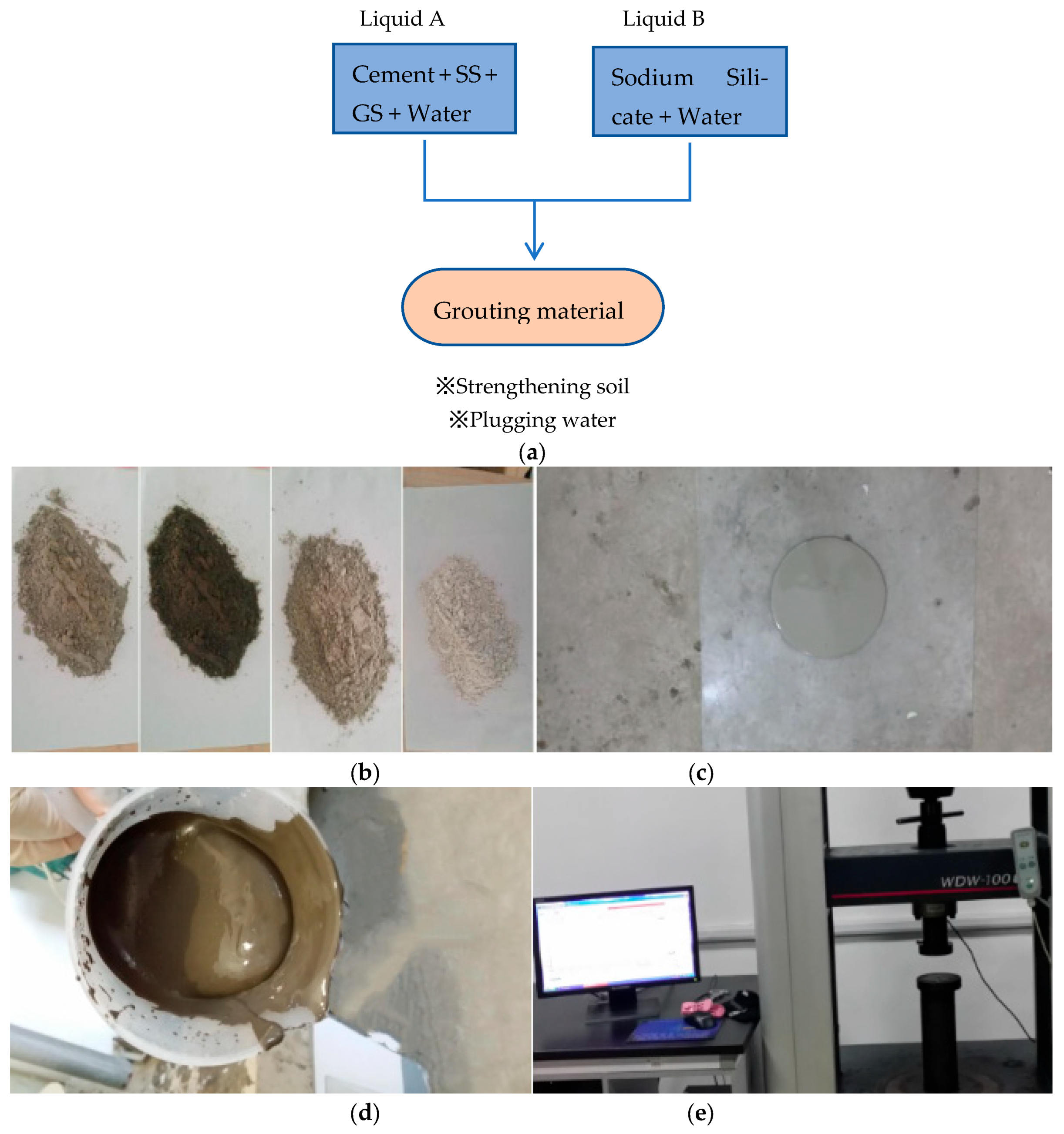
Figure 1. Conceptual diagram of the grouting method: (a) The production process and function of the grouting materials; (b) Raw material; (c) Fluidity test procedures; (d) Gel time test procedures; (e) Strength test procedures.
Buildings 15 04138 g001
Figure 2. Raw material particle size distribution (%).
Buildings 15 04138 g002
Figure 3. Effect of the sodium silicate volume on the fluidity of the grouting material.
Buildings 15 04138 g003
Figure 4. Effect of the sodium silicate volume on the gel time of the grouting material.
Buildings 15 04138 g004
Figure 5. Effect of the sodium silicate volume on the compressive strength.
Buildings 15 04138 g005
Figure 6. Pore structure of the grouting material for A5: (a) log differential intrusion; (b) incremental intrusion volume.
Buildings 15 04138 g006
Figure 7. XRD patterns of A5 grouting materials on the (a) 3rd day and (b) 28th day.
Buildings 15 04138 g007
Figure 8. Effect of the water–binder ratio on the fluidity of the grouting material.
Buildings 15 04138 g008
Figure 9. Effect of the water–binder ratio on the gel time of the grouting material.
Buildings 15 04138 g009
Figure 10. Effect of the water–binder ratio on the compressive strength of the grouting material.
Buildings 15 04138 g010
Figure 11. Effects of the cement content and industrial waste ratio on the fluidity of grouting materials.
Buildings 15 04138 g011
Figure 12. SEM images analysis of A2 and A5 grouting materials on the 3rd and 28th day: (a) SEM image of C-S-H gel in A2 grouting materials on the 3rd day; (b) SEM image of C-S-H gel in A2 grouting materials on the 28th day; (c) SEM image of C-S-H gel in A5 grouting materials on the 3rd day; (d) SEM image of C-S-H gel in A5 grouting materials on the 28th day.
Buildings 15 04138 g012aBuildings 15 04138 g012b
Figure 13. Effects of the cement content and industrial waste ratio on the gel time of the grouting material.
Buildings 15 04138 g013
Figure 14. Effects of the cement content and industrial waste ratio on the strength of the grouting material.
Buildings 15 04138 g014
Figure 15. Plots of the gel time of the grouting material versus retarding agent dosage.
Buildings 15 04138 g015
Figure 16. Effect of retarding agent dosage on the 3 d compressive strength of the grouting material.
Buildings 15 04138 g016
Figure 17. Effect of retarding agent dosage on the 28 d compressive strength of the grouting.
Buildings 15 04138 g017
Figure 18. Production of grouting materials.
Buildings 15 04138 g018
Figure 19. Effect of moisture content on the consolidation strength of sand.
Buildings 15 04138 g019
Figure 20. Stress–strain behaviour of the samples.
Buildings 15 04138 g020
Figure 21. Effect of particle gradation on the consolidation strength of sand.
Buildings 15 04138 g021
Figure 22. Stress–strain curves of different particle gradations.
Buildings 15 04138 g022
Figure 23. Effect of slurry dosage on the consolidation strength of different kinds of sand: (a) Effect of the slurry dosage on the 1 d, 3 d, 7 d and 28 d consolidation compressive strength of gravel sand; (b) Effect of the slurry dosage on the 1 d, 3 d, 7 d and 28 d consolidation compressive strength of coarse sand; (c) Effect of the slurry dosage on the 1 d, 3 d, 7 d and 28 d consolidation compressive strength of medium sand.
Buildings 15 04138 g023
Figure 24. Stress–strain curves for different slurry dosages.
Buildings 15 04138 g024
Table 1. Chemical composition of the raw materials (% by weight).
Raw MaterialSiO2CaOMgOAl2O3Fe2O3MnOTiO2f-CaOLoss
Cement22.6562.602.914.653.10--0.811.75
Steel slag14429.9420---5
Fly ash59.294.241.1826.642.57--0.355.60
Ground Slag3843890.380.20.4-2.56
Table 2. Particle gradation and composition of different sandy soil.
CompositionGravel GrainGrittySiltyClay Particle
Particle Gradation/mm>2.02.0–0.50.5–0.250.25–0.0750.075–0.0050.005–0
Gravel sand35.022.820.412.69.20
Coarse sand16.140.818.213.411.30.2
Medium sand11.224.938.114.311.20.3
Table 3. Different grouting material systems.
SampleC
%
SS
%
FA
%
SL
%
Fluidity
mm
Gel
Time
s
Concretion Rate
%
3 d Compressive Strength
MPa
28 d Compressive Strength
MPa
A0100000270259911.9516.43
A160400027840989.6214.27
A26020020280439810.9515.82
A340600028347978.8716.34
A440060028549977.9416.03
A54030030288519611.0717.58
A64003030291549710.7816.67
Note: C = cement; SS = Steel slag; FA = fly ash; SL = Ground slag.
Table 4. Construction parameters for grouting engineering.
ParameterDescription
Grouting pressureInitial grouting pressure: 0.1–0.4 MPa; final grouting pressure: 0.5 MPa.
Grouting completion criterionWhen the designed final pressure is reached and grouting continues for more than 10 min or when the grout leaks out, the grouting is considered complete.
Grouting pipe designThe external pipes are steel pipes with a diameter of Ф40 mm, a wall thickness of 3.5 mm, and a length of 6 m. The upper part is exposed by 15–20 cm.
Grouting quantityThe grouting volume per section was 95 L, and the grouting volume per hole was 750 L/hole.
Gel time testingOn-site slurry preparation was performed, with the gel time controlled between 1 and 8 min.
Grouting effect inspectionAfter industrial waste residue double-liquid grouting was completed, core sampling and observations during construction indicated that the compressive strength of the consolidation reached 0.5–3 MPa after 3 days. The entire loose soil mass was consolidated, and surface deformation was controlled within 30 mm.
Disclaimer/Publisher’s Note: The statements, opinions and data contained in all publications are solely those of the individual author(s) and contributor(s) and not of MDPI and/or the editor(s). MDPI and/or the editor(s) disclaim responsibility for any injury to people or property resulting from any ideas, methods, instructions or products referred to in the content.