Abstract
The extensive development of urban underground space increases the risk of deformation to adjacent structures during deep excavations. This study investigates the response of three low-strength strip-foundation buildings (#4, #8, and #11 of the Ninggong Apartment) in Nanjing, China, affected by the excavation of an adjacent super-long, narrow subway station. The site is located in a typical soft alluvial area of the Yangtze River, characterized by highly compressible and sensitive soil, which poses substantial challenges. Pre-construction ground improvement was implemented to mitigate the impacts of diaphragm wall trenching; however, monitoring data indicated that buildings’ settlements of this stage still reached 28.2%, 24.8%, and 27.2% of their final values, with extensive influence zones. Subsequent excavation of the eastern and middle sections induced further cumulative and differential settlements, raising safety concerns and necessitating structural strengthening before adjacent western excavation. An integrated underpinning system, combining anchor static pressure steel pipe piles with a raft foundation, was adopted. Although short-term settlement increased during pile and raft installation, post-strengthening settlement rates decreased significantly. The adjacent western excavation caused only 13.3% of the settlement to be observed during the middle section’s excavation. All buildings were ultimately protected from excessive deformation. The protective strategies and lessons learned provide practical guidance for similar projects.
1. Introduction
In recent years, the construction of underground transportation systems in densely populated cities has advanced rapidly and effectively to alleviate traffic congestion. However, such infrastructure construction is frequently accompanied by large-scale deep excavations. Soil removal alters the initial ground stress state, inducing soil deformation and movement [1,2], which adversely affects adjacent superstructures and buried utilities [3,4,5,6,7]. Consequently, deep excavations for underground space development in dense urban environments pose significant risks to nearby structures and facilities, potentially causing cracking, tilting, or even structural collapse [8,9]. Therefore, ensuring the safety of existing adjacent structures and utilities is always the paramount priority for engineers and researchers.
Extensive research has examined the responses of buildings adjacent to deep excavation through field monitoring, laboratory testing, and numerical simulation, yielding significant findings [2,5,8,10,11,12,13,14,15,16,17,18,19,20]. Moreover, to mitigate supporting wall deflection and ground settlement, strengthening the bracing system and enhancing passive resistance are commonly implemented auxiliary measures in engineering practice [21,22,23]. Beyond conventional bracing systems, researchers have developed buttress walls [21,24] and cross walls [25,26,27] to reinforce diaphragm walls. While the aforementioned methods serve as alternative protective measures for adjacent structures, auxiliary strengthening of bracing systems remains insufficient to guarantee the safety of nearby existing buildings—particularly shallow-founded structures with inadequate superstructure safety margins. This deficiency is exacerbated in thick, highly compressible, low-strength sensitive soft soils under high groundwater levels. Severe structural damage has been documented in multiple projects involving shallow-founded buildings adjacent to deep excavations [3,17,28]. Common remedial techniques implemented to reinforce buildings near excavation zones include grouting, micro-piling, soil nailing, concrete caissons, bored piles, and pressure pipe piles [20,29,30,31]. Nevertheless, research on the protection of shallow-founded buildings with insufficient safety margins of superstructures in low-lying alluvial soft soil under high-level groundwater conditions remains scarce. Based on a case study of a subway station excavation in the soft alluvial soils of the Yangtze River area, this paper investigates the response of adjacent shallow-founded buildings and explores effective protective measures. Through field monitoring, the study reveals the static deformation behavior of buildings throughout the entire process before, during, and after reinforcement and validates an integrated underpinning system combining anchor static pressure steel pipe piles with a raft foundation. The proposed system effectively controlled excavation-induced settlements, and the findings provide practical guidance for protecting vulnerable structures in similar geological settings.
2. Project Description
2.1. Project Profile
Nanjing Metro Line 4 spans from Longjiang Station in the west to Xianlin East Station in the east. Longjiang Station (Figure 1), located beneath Caochangmen Street, is a two-story underground island station that spans Lijiang Road and Jiangdong North Road and has an L-shaped upper crossing transfer with the planned Zhongbao Station on Line 9. As the western terminus of Phase I of Metro Line 4, the station accommodates train turnaround and parking functions while reserving provisions for the shield reception of Phase II (west extension), making it one of the most complex constructions of entire line. The station stretches 520.6 m in total, with entrances and exits, one fire escape exit, and three wind shelters. The standard section measures 21.7 m wide, with an excavation depth of 19.7 m, a diaphragm wall depth of 37.5 m, and a wall thickness of 1 m. The end well is 26 m wide, with an excavation depth of 21.5 m, a diaphragm wall depth of 41.5 m, and a wall thickness of 1 m. The transfer part reaches 27.7 m excavation depth, with a diaphragm wall depth of 50 m and a wall thickness of 1.2 m. The diaphragm walls employ H-shaped steel joints. To mitigate spatiotemporal effects on surrounding soil and buildings, this super-long deep pit is divided into three east-to-west construction sections: the east section (176 m), middle section (224.6 m), and west section (120 m, adjacent to the Ninggong Apartment).
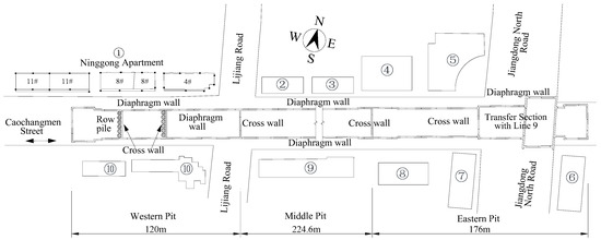
Figure 1.
Plan layout of project site.
2.2. Engineering Geological Conditions
The site of Longjiang Station features a flat terrain with ground elevations ranging from 6.70 m to 8.06 m, and the geomorphology is characterized by an alluvial plain of the Yangtze River floodplain. Prior to design, the geological conditions of the site had been derived by performing a series of field and laboratory tests; some physical and mechanical parameters of the soil layers are shown in Table 1. Generally, the soil layers within the site, from top to bottom, are as follows: (i) fill layer (Layer ①), with a thickness of 1.5–6.5 m; (ii) soft to flow-plastic silty clay and muddy silty clay (Layer ②-2b), with a thickness of 10.4–21.8 m; (iii) flow to soft-plastic silty clay mixed with silt (Layer ②-3b), with a thickness of 12.8–18.9 m; (iv) soft to flow-plastic silty clay (Layer ②-4b), with a thickness of 14.5–28.5 m; (v) soft to plastic silty clay with gravel sand (Layer ③-4e), with a thickness of 0.2–3.9 m; (vi) strongly weathered silty mudstone and muddy siltstone (Layer K-2), with a thickness of 0.5–5.7 m; and (vii) moderately weathered silty mudstone and muddy siltstone (Layer 4-3), with a thickness of 1.0–6.2 m. Additionally, the site is adjacent to the Yangtze River and Qinhuai River, resulting in abundant groundwater resources. The long-term phreatic water level was located 1.3–2.4 m below ground level, with fluctuations generally corresponding to topographic variations. The groundwater level is significantly influenced by seasonal variations, with an annual fluctuation range of approximately 1.0 m. The site presents challenging geological conditions and complex hydrogeological conditions, where the overburden consists predominantly of alluvial-deposited saturated soft soils exhibiting high to medium–high compressibility, with notable characteristics including significant thickness, high compressibility, low strength, and high sensitivity, making them susceptible to thixotropic and flow-plastic deformation during excavation. The low-lying topography, combined with a substantial aquifer thickness and relatively high groundwater level, along with horizontally interbedded silt layers beneath the foundation slab, may lead to potential challenges including water inrush, sand boiling, and post-construction settlement, as well as construction issues such as necking in diaphragm walls and piles.

Table 1.
Physical and mechanical parameters of soil layers.
2.3. Existing Building Conditions
A total of 11 buildings are located adjacent to the deep excavation of Longjiang station, as shown in Figure 1. Building ① (Ninggong Apartment) is a brick-concrete structure with strip foundations, situated 12–15 m from the station. Buildings ②, ③, ④, ⑤, ⑦, and ⑩ feature frame structures with 4–30 stories, supported by cast-in-place piles or precast piles (building ④). Pile diameters range from 500 to 1000 mm, and lengths vary between 32.5 and 61 m. Buildings ⑥ and ⑧ adopt frame-shear wall structures with 19 and 26 above-ground stories, respectively, utilizing cast-in-place pile foundations (700–1000 mm in diameter and 52–55 m in length). Building ⑨ is a six-story brick-concrete structure with vibro-flotation cast-in-place piles (400 mm in diameter and 21 m in length). According to field investigations and the monitoring during diaphragm wall trenching, deep excavation most significantly affects the Ninggong Apartment, especially on buildings 4#, 8#, and 11# (Figure 2a). Safety monitoring and deformation control of these structures constitutes a critical task for this project and forms the research focus of this paper. The Ninggong Apartment, constructed in 1994, is a seven-story brick-concrete structure with a height of 21.75 m (Figure 2b). The plan dimensions of residential buildings 4#, 8#, and 11# are approximately 40.2 m × 14.6 m, 43.7 m × 14.6 m, and 46.7 m × 14.6 m, respectively. The 1st to 3rd floors use Mu10 bricks with M7.5 mixed mortar, while the 4th floor and above employ Mu10 bricks with M5 mixed mortar. All cast-in-place reinforced concrete members have a strength grade of C20, reinforced with Grade I and Grade II steel bars. The kitchen, toilet, and stairwell areas feature cast-in-place reinforced concrete slabs, whereas the remaining floor slabs are precast reinforced concrete slabs. The strip foundation has a burial depth of 1.2 m, a thickness of 350 mm, and three width configurations: 800, 2200, and 2400 mm. The ground soil was improved using the single-axis deep mixing method with cement–soil piles, featuring designed pile lengths of 12 m and diameters of 500 mm and 600 mm. As per design requirements, the treated soil achieves a bearing capacity of 130 kPa.
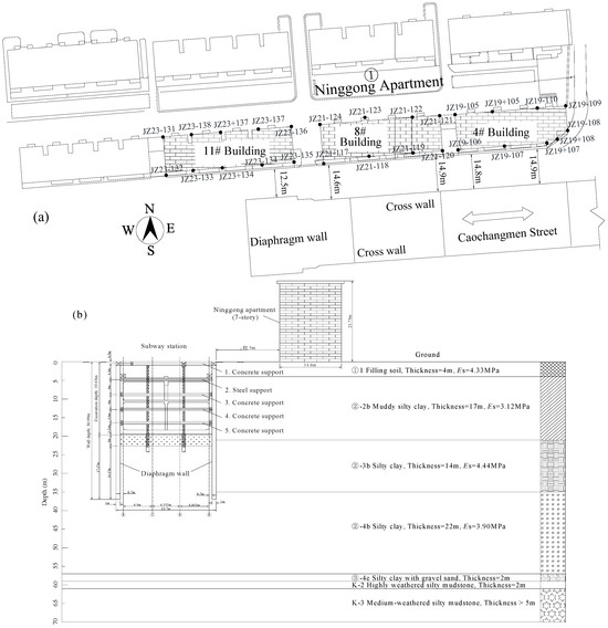
Figure 2.
Buildings 4#, 8#, and 11# of Ninggong Apartment adjacent to the deep pit of Longjiang station: (a) plan layout of buildings and monitoring points; (b) cross-section of buildings 11# and the pit.
2.4. Ground Improvement Before Trenching Construction and Excavation
The retaining structure of the station adopts diaphragm walls, with the wall toes embedded in the ②-3b silty clay mixed with a silt layer. Given the complex surrounding environment, to prevent potential adverse effects on adjacent structures caused by trench wall collapse during diaphragm wall construction, based on local engineering practice and relevant specifications, triple-axis auger mixing piles (φ850@600) were employed to reinforce the trench walls west of Lijiang Road prior to the diaphragm wall’s construction. The reinforcement extended 24.7 m in length with a cement content of 20% and water–cement ratio of 1.0. The excavation base of the east end well is situated within the ②-3b layer, while the standard section base lies across both ②-3b and ②-2b layers, and the west end well base rests in the ②-2b layer. Both ②-2b and ②-3b layers exceed 10 m in thickness and exhibit poor mechanical properties. To mitigate the adverse effects of soft soil on structural deformation, triple-tube high-pressure jet grouting piles (φ800@600) were implemented to reinforce the base soils prior to excavation, thereby enhancing soil strength. In the east end well area, skirt-and-grid reinforcement was adopted with both skirt and grid widths of 3 m, extending 3 m below the excavation base. The standard section employed grid-style strip reinforcement with a 3 m width and 3 m depth below the base. The western section (west of Lijiang Road) utilized full-area reinforcement spanning from 10 m above to 3 m below the excavation base.
3. Investigation of Building Safety Issues and Strengthening Technology
Ninggong Apartment, located adjacent to the western pit, shallow-founded with a relatively low overall structural strength grade. During diaphragm wall construction, the building already exhibited significant absolute settlement and differential settlement, with both the maximum cumulative settlement and local inclination exceeding monitoring alarm thresholds.
3.1. Survey of Building Safety Issues
After on-site survey and independent structural safety assessment, the following multiple concerning issues, as shown in Table 2 and Figure 3, were identified in buildings 4#, 8#, and 11# of Ninggong Apartment.
Table 2.
The safety issues of Ninggong Apartment.
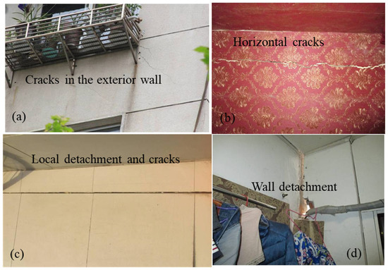
Figure 3.
Damage to several Ninggong Apartment buildings: (a) exterior wall cracks in building 4#; (b) horizontal cracks of inner wall in building 4#; (c) local detachment between beams and walls of building 8#; (d) wall detachment in building 8#.
In building safety assessments, structural damage levels are typically evaluated through three key indicators: surface appearance, structural inclination, and maximum crack dimensions. Following the classification framework established by Boscardin and Cording [10], visible damage severity is categorized into six progressive levels: (i) negligible, (ii) very slight, (iii) slight, (iv) moderate, (v) severe, and (vi) very severe. GB50292-2015-Standard for Appraisal of Reliability of Civil Buildings of China [32] classifies building safety assessment into four distinct levels: Asu, Bsu, Csu, and Dsu. According to the standard: Asu denotes buildings in excellent condition; Bsu indicates structures with minor deficiencies; Csu represents buildings requiring restricted use; and Dsu signifies hazardous structures requiring immediate attention. The safety inspection and assessment of Ninggong Apartment revealed that buildings 4#, 8#, and 11# exhibited severe unauthorized structural alterations, with calculations verifying that certain load-bearing components had critically insufficient capacity and should be classified as hazardous elements; additionally, buildings 4# and 8# demonstrated inadequate structural reinforcement measures, including partial demolition of lateral force-resisting walls resulting in compromised structural integrity, while all three buildings (4#, 8#, and 11#) showed dangerous deterioration in staircase roof panels and stair slabs where exposed reinforcement had corroded to hazardous levels; the buildings exhibit predominant southeastward tilting, aligning with the pit inclination direction, where buildings 4#, 8#, and 11# demonstrate tilt rates of 3.3‰, 2.3‰, and 3.6‰, respectively (not exceeding the 4‰ limit specified in the code (GB50007-2011) [33] for design of building foundations ≤ 24 m in height); furthermore, extensive new cracking has been observed with maximum crack widths reaching 2.6 mm, indicating significant structural distress. In accordance with Code GB50292-2015, buildings 4#, 8#, and 11# received a comprehensive Csu (restricted use) rating, indicating that they possess significant safety hazards that require immediate reinforcement measures to mitigate risks, particularly considering the potential exacerbation from subsequent construction activities.
3.2. Investigation of Building Strengthening Technology
To ensure structural safety during subsequent construction at Ninggong Apartment, deformation control measures must be implemented while maintaining functionality and enhancing structural safety margins. In the western pit, the support system was optimized from original six levels (with reinforced concrete supports at the first and fourth levels and steel supports at the remaining levels) to five levels (one steel support at the second level and reinforced concrete supports at all other levels, as shown in Figure 2) to enhance deformation control of the diaphragm wall during excavation. Additionally, two underpinning schemes were thoroughly analyzed to enhance the bearing capacity of the foundation of Ninggong Apartment.
3.2.1. Rock-Socketed Pile and Box Foundation Underpinning
The rock-socketed pile and box foundation underpinning plan implementation involves five sequential construction phases. (i) Structural rehabilitation of ground-floor shops, comprising the removal and reconstruction of compromised wall columns and restoring and repairing the demolished, renovated, and damaged parts of the interior walls; installation of structural columns and ring beams on exterior walls; and reinforcing the interior walls with steel mesh-reinforced mortar surfacing. (ii) Two rows of bored cast-in-place piles are arranged and constructed along the longitudinal direction on the north and south sides of the buildings: the first row of piles has a diameter of 1200 mm spaced 2.6 m from the exterior walls with 64 m length; the second row of piles has a diameter of 1000 mm spaced 2.6 m from the primary row with 50 m length, as detailed in Figure 4a. (iii) Following the completion of pile curing, a pile cap replacement structure is constructed: excavation of 2.6 m-deep foundation pits at bilateral pile locations and the pile caps; construction of pile caps with support shims/blocks and installation of lateral bracing systems including inter-pile tie beams and retaining walls; erection of longitudinal beams on the pile top with steel sections penetrating and welded to web reinforcement of the box foundation; sequential placement of prestressed anchor blocks, monolithic concrete casting (ensuring continuous prestressed system integration); and post-tensioning cable installation after initial concrete setting. (iv) Reconstruction and reinforcement of the building’s foundation: clearing the space on the ground-floor and excavate to the bottom surface of the original strip foundation; surface preparation includes cleaning, roughening, rebar planting, and anchoring of the existing strip foundation, and open holes in the brick wall to 0.5 m above the original ground; staged casting of the new box foundation in the order of bottom plate, web plate, and top plate with 1700 mm-high box beams (Figure 4b). (v) Staged tensioning, jacking, and load transfer implementation of the structure: symmetrical installation of two 500-ton jacks longitudinally positioned at the pile cap bearings, integrated with a synchronous lifting control system; commencement of prestressing operations upon achieving design-specified concrete strength; three-stage alternating tensioning and lifting sequence continuing ensuring controlled stress transfer throughout the process; and the implementation of post-tensioning grouting for complete duct sealing and structural integration.
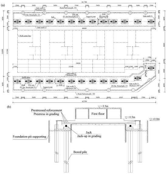
Figure 4.
The rock-socketed pile and box foundation underpinning (unit: mm): (a) the location of bored pile; (b) the profile of foundation underpinning.
3.2.2. Anchor Static Pressure Steel Pipe Pile Strengthening
The static pressure pile and micro-pile strengthening technology has been extensively validated in practical engineering applications [34,35]. The proposed static pressure pile reinforcement system, as shown in Figure 5, incorporates a dual-level protection strategy: (i) primary protection through a 500 mm-thick raft foundation cast atop the original strip foundation, replacing the shallow foundation with 377 mm diameter and 57 m length anchor static pressure steel pipe piles; and (ii) secondary protection featuring dynamically adjusted reserve piles based on real-time monitoring results.
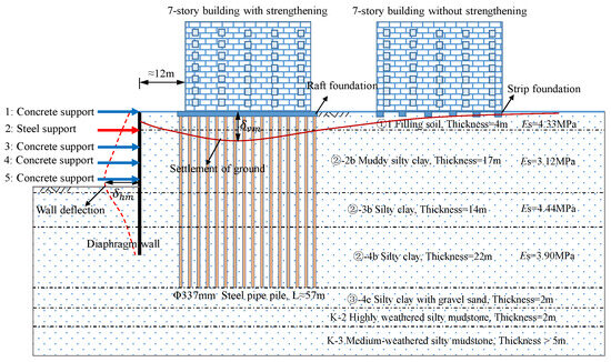
Figure 5.
The diagram of static pressure pile strengthening and underpinning.
After the installation of static pressure piles beneath the building, the foundation load was jointly borne by both the raft and piles. To verify the reliability of this strengthening plan, the load distribution ratios across different raft foundations in building 4# were compared. A preliminary evaluation of varying load ratio effects was conducted using PKPM software (2016) [36]. The JCCAD module within PKPM was employed to calculate foundation settlement values, incorporating complete datasets of soil layer properties, building characteristics, and pile–raft foundation parameters. The resulting building settlement calculations are presented in Table 3.
Table 3.
The settlement calculation results of building 4#.
The computational results in Table 3 demonstrate that increasing the number of static pressure piles and raising the load-bearing ratio of the pile significantly reduced the settlement of building 4#. However, excessive addition of piles proved uneconomical and could substantially prolong the construction period. To balance cost effectiveness and structural performance, the dual-line defense approach mentioned above was proposed, incorporating both primary engineering piles and reserve piles. The strengthening design for building 4# ultimately incorporated 87 engineering piles and 30 reserve piles. Post-installation analysis using PKPM software (2016) yielded theoretical settlement values ranging between 34.3 mm and 35.0 mm, demonstrating high uniformity in the foundation settlement. These results confirm that the static pressure pile reinforcement system effectively controls building settlement, achieving both structural stability and settlement mitigation objectives.
3.2.3. Comparison of Two Strengthening Schemes
A comprehensive comparison of the two schemes leads to the following conclusions. In terms of the impact on building functionality, the pile-box foundation underpinning scheme employs bored cast-in-place piles that require significant construction space. With the original foundation buried 1.2 m deep and the new box beam standing 1.7 m high, this solution reduces the first-floor clearance by 0.5 m, substantially affecting original functionality of the building. In contrast, the anchor’s static pressure pile strengthening plan utilizes segmented steel pipe piles that can be installed in confined spaces using reaction frames anchored to the raft. This solution maintains the original spatial configuration, featuring a 500 mm-thick raft whose bottom surface aligns with the original foundation top while remaining entirely below ground level, thereby preserving the functionality while providing effective structural reinforcement. The comparison clearly demonstrates the superior space efficiency and functional preservation of the anchor static pressure pile method. In terms of the impact on the existing structure during construction process, the pile-box foundation underpinning induces ground settlement through soil unloading during bored pile installation, which particularly concerning given that the piles are very close to the buildings. Furthermore, the segmented prestressing process in the box beam prevents synchronous tensioning across sections, risking localized deformation and potential superstructure damage. Conversely, the anchor’s static pressure pile strengthening scheme disturbs long-consolidated strata during pile pressing, generating additional settlement as the soil reconsolidates. While the static pressure method minimizes vibration compared to drilling, both approaches unavoidably affect the building during implementation. In terms of the impact of the construction on the surrounding environment, the pile-box foundation solution necessitates the demolition of adjacent infrastructure including two-story commercial units along Lijiang Road, green spaces, bicycle shelters, and high-voltage power lines, while its bored pile construction process further generates substantial disturbances to neighboring residential structures. In contrast, the anchor’s static pressure pile solution demonstrates markedly reduced environmental impact during implementation in urban contexts where minimizing disruption to adjacent structures and public infrastructure is particularly paramount. Regarding deformation resistance improvement, the bored cast-in-place piles in the pile-box foundation underpinning are longer and need to be embedded in the medium-weathered rock layer, while the steel pipe piles of the anchor static pressure pile scheme use fine sand as the bearing layer. Obviously, the pile-box foundation underpinning scheme may be relatively more advantageous for controlling the settlement of the buildings during the following excavation process. Economically, the estimated cost of the pile-box underpinning scheme is about CNY 39.11 million (excluding the cost of external demolition) versus 24.35 million for the static pressure alternative; meanwhile, the pile-box scheme requires a substantially longer construction period. According to the comparison results, the strengthening scheme of the anchor’s static pressure steel pipe pile is performed in the project.
3.3. Construction Process of Anchor Static Pressure Pile
By adopting the raft foundation and implementing anchor static pressure piles, the load transfer mechanism of the overall structure is modified. The original system, which relied on a superstructure-strip foundation–soil interaction, is transformed into a more robust superstructure-raft and steel pipe pile–soil system. The key construction steps of this reinforcement project can be categorized into four main components. (i) Structural restoration and reinforcement: the bottom floor of the building, having undergone extensive demolition and reconstruction, constitutes the weakest layer in the overall structural system. To address this, the structural integrity of this floor was first restored in accordance with the original design drawings. Subsequently, the rigidity of the bottom floor was enhanced by introducing additional structural columns and ring beams. This measure ensures the stability of the upper structure during subsequent foundation reinforcement, thereby mitigating the risk of secondary damage. (ii) Raft foundation construction: following the structural reinforcement of the first floor, the ground was excavated down to the base level of the existing strip foundation. A 500 mm-thick C40-grade raft foundation was then cast, with its top elevation set at −0.35 m and its bottom surface aligned flush with the top surface of the original strip foundation. The connection between the raft and the roughened strip foundation was achieved through planted reinforcement (Figure 6a). At the wall–raft interface, 200 mm × 500 mm through-blind beams were installed in the east–west direction, with grooves spaced at 1 m intervals (Figure 6b). Additionally, pile holes were pre-reserved in the raft at designated pile-pressing locations and corresponding boreholes were drilled into the underlying strip foundation to facilitate subsequent pressure pile installation. Upon completion, the raft foundation replaces the original strip foundation, transferring the structural load to the newly constructed raft (Figure 6c).
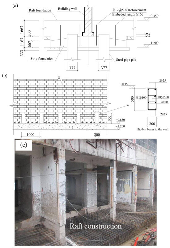
Figure 6.
Connection method of raft foundation with adjacent structure (unit: mm): (a) connection of raft and strip foundation; (b) connection of raft and wall; (c) raft construction.
(iii) Anchor static pressure steel pipe pile construction: the open-ended steel pipe piles with 377 mm diameter and 57 m length were adopted. These piles were designed with a characteristic bearing capacity of ≥900 kN and require a minimum installation load of 1500 kN. Post-installation, each pile carried out core-filling treatment to enhance its load-bearing performance. The piles were strategically arranged in bilateral configurations along load-bearing walls to efficiently transfer superstructure loads to the deeper foundation strata. This configuration optimizes load distribution while minimizing potential differential settlement. Due to space limitations, a segmented installation method was adopted, whereby each segment was connected sequentially until the pile tip reached the bearing layer (fine sand layer). The installation process for each building was divided into three stages: the first and second stages involved engineering piles and the third stage served as a safety reserve. Figure 7, Figure 8 and Figure 9 illustrate the pile layout design for buildings 4#, 8#, and 11# at different stages of installation. To mitigate the impact of soil squeezing on the verticality of pressed piles and minimize uneven building settlement, the construction sequence for each row of piles proceeded longitudinally, commencing from the center of the building and progressing outwards towards both sides. This sequential construction approach is illustrated in Figure 7a–c for building 4#, with buildings 8# (Figure 8) and 11# (Figure 9) following an analogous procedure.
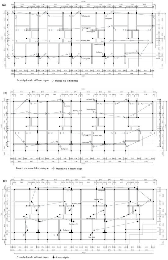
Figure 7.
The construction of strengthening static pressure pile for building 4#: (a) pressed piles in first stage; (b) pressed piles in second stage; (c) reserved piles of third stage.
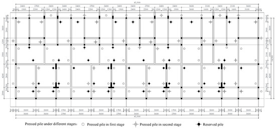
Figure 8.
The distribution and construction of strengthening static pressure pile for building 8#.
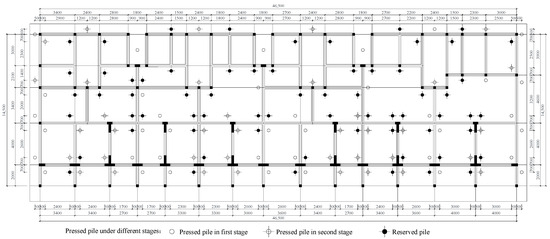
Figure 9.
The distribution and construction of strengthening static pressure pile for building 11#.
(iv) Anchoring and sealing piles: pile pressing was terminated when the pile tip reached the design depth or the installation force exceeded the design value and remained stable for a duration exceeding 5 min. Temporary pile-sealing construction was then undertaken, involving the arrangement of a steel plate base and I-beam reaction beam, concurrently with settlement observation of the building. Following stabilization of the settlement data, reinforcement bars were anchored and the piles were permanently sealed (Figure 10). The procedure for the anchored pile sealing includes the following steps: clearing the soil around the pile cap beam area of the jacking hole; roughening and cleaning the walls of the jacking hole; removing mud and water from the jacking hole; placing anchoring reinforcement in the pile hole and pouring C45 micro-expansive early strength concrete for sealing; roughening and cleaning the surface of the base slab; welding cross-steel bars and placing additional reinforcement in the pile hole; casting a 150 mm thick pile cap using C45 concrete; and inspecting the sealed pile hole for any water leakage.
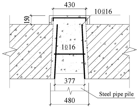
Figure 10.
The anchoring and sealing of static pressure piles.
3.4. Bearing Capacity of Static Pressure Pile
According to the pressing records from the construction site, the pressed pile length, final installation load, and soil plug length of buildings 4#, 8#, and 11# could be obtained as shown in Table 4.
Table 4.
The statistic results of static pressure pile.
As shown in Table 4, the pressed lengths of the steel pipe piles vary significantly, with the maximum difference reaching 20 m. This variability is related to differences in the local underlying strata. When the local strata are partially sandwiched with hard soil layers, the bearing capacity requirements can be satisfied with shorter penetration lengths. All the pressed steel pipe piles exhibit obvious soil plug effects, with the height of the soil core within the steel pipes ranging from approximately 0.38 to 0.76 times the pile length, indicating that these pressed steel pipe piles all demonstrate closed pile bearing characteristics. Figure 11 shows the relationship between the final installation load and the aspect ratio of different stages of static pressure piles.
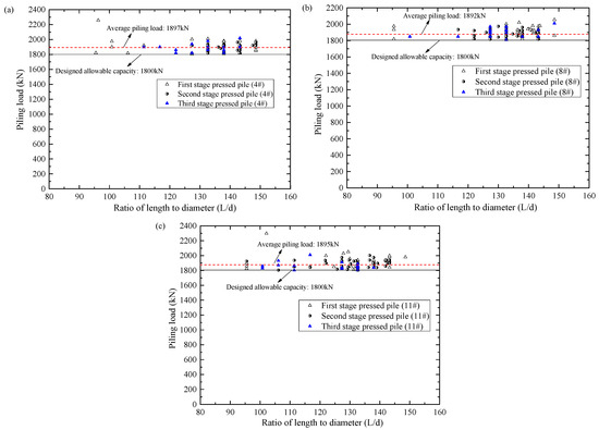
Figure 11.
The records of static pressure piles under different stages: (a) building 4#; (b) building 8#; (c) building 11#.
As illustrated in Figure 11, the average final installation loads for the static pressure piles in buildings 4#, 8#, and 11# are 1897 kN, 1892 kN, and 1895 kN, respectively. These values are approximately 5% greater than the design ultimate bearing capacity of a single pile, which is 1800 kN. The length-to-diameter ratio consistently falls between 90 and 150, a value significantly exceeding that of conventional super-long piles. An analysis of length-to-diameter ratios across different stages of static pressure piles reveals significant variation in the first stage, ranging from 100 to 150, while the second stage and reserve piles exhibit ratios primarily between 120 and 145. To further assess whether the bearing capacity and settlement of these super-long piles meet design specifications, on-site static load tests of vertical bearing capacity were conducted on three, two, and two piles from the static pressure engineering piles of buildings 4#, 8#, and 11#, respectively. The test results are presented in Table 5.
Table 5.
The vertical bearing capacity results of test piles.
It can be seen from the above test results that the settlement of the seven test piles at the maximum test load of 1800 kN is between 24.9 mm and 30.4 mm. Meanwhile, the load–displacement curve demonstrates a characteristic slow deformation trend, and the maximum settlement, ranging from 6.60% to 8.06% of the pile diameter, is significantly less than the 10% [37] or 15% [38] of the pile diameter, specified in certain guidelines. Consequently, the actual ultimate bearing capacity of the test pile is expected to exceed 1800 kN, and the static pressure piles in this project meet the design requirements.
4. Discussion of Building Response Based on Field Monitoring
This project is a typical long–narrow deep excavation, employing a segmented construction method overall. According to the time sequence, the construction process can be divided into the following seven stages. Stage I: construction of diaphragm wall. Stage II: excavation of the east section. Stage III: excavation of the middle section. Stage IV: preparation before building strengthening. Stage V: building strengthening. Stage VI: excavation of the west section. Stage VII: construction of station main structure. Multiple settlement monitoring points were installed along the sides and corners of the three observed buildings (Figure 2a), and the initial values were measured before the construction of the guide wall. Through long-term on-site monitoring, the settlement data of buildings 4#, 8#, and 11# at different stages were obtained as shown in Figure 12.
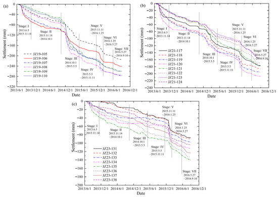
Figure 12.
The monitoring settlement data at different stages: (a) building 4#; (b) building 8#; (c) building 11#.
Furthermore, based on the monitoring data, the settlement and the average settlement rate in different construction stages were statistically obtained, as shown in Table 6.
Table 6.
The settlement statistics of buildings 4#, 8#, and 11# of Ninggong Apartment under different stages.
Figure 12 and Table 6 demonstrate consistent settlement patterns across stages for buildings 4#, 8#, and 11#. In terms of magnitude, building 4# exhibits the greatest settlement, followed by building 8#, with building 11# showing the least settlement. During the construction of the diaphragm wall (Stage I), adjacent buildings 4#, 8#, and 11# experienced varying degrees of settlement, with the maximum settlement 68.10 mm (4#: JZ19-106), 48.48 mm (8#: JZ21-119), and 38.23 mm (11#: JZ23-135). These values represent 28.2%, 24.8%, and 27.2% of their respective final cumulative settlements. Generally, the construction of a diaphragm wall typically exerts a relatively minimal influence on surrounding structures, but this location of project within the Yangtze River’s low-lying alluvial area introduced critical challenges. The soft clay strata exhibited high sensitivity and pronounced rheological behavior, amplifying ground disturbances. Consequently, the excavation process induced significant settlement in nearby shallow-foundation buildings. Although the east section excavation (Stage II) was located over 220 m from Ninggong Apartment, monitoring data revealed continued settlement progression in buildings 4#, 8#, and 11#, with the maximum settlement 97.02 mm (4#: JZ19-106), 84.65 mm (8#: JZ21-119), and 63.71 mm (11#: JZ23-135). Notably, the settlement of monitor points close to the pit was significantly larger than that of the farther side.
During the excavation of the middle section (Stage III), substantial settlement increases were observed in all three buildings, accompanied by a significant acceleration in settlement rate. After the excavation of the middle section was completed, the maximum settlement magnitude, 202.52 mm, and peak settlement rate, 0.60 mm/d, were recorded at monitoring point JZ19-108 in building 4#. A comparison of the data of Stage II and Stage III in Table 6 reveals that the middle section’s excavation induced significantly more pronounced settlement effects in all three buildings than the east section’s excavation. Given the significantly increased settlement risks observed during previous phases, it is evident that without risk-reduction and strengthening measures, subsequent excavation of the western section would induce substantially more extensive and severe building settlement. Therefore, prior to the western section’s excavation, buildings 4#, 8#, and 11# underwent strengthening using super-long static pressure steel piles to enhance the structural safety margins.
In the preparation before the building strengthening stage (Stage IV;), the settlement of the adjacent building continued to increase at basically the same rate as in Stage II. At the end of Stage IV, the maximum cumulative settlements reached 236.22 mm (building 4#), 153.84 mm (building 8#), and 92.44 mm (building 11#). It indicated that the settlement and deformation of buildings in soft soil exhibit significant time-dependent characteristics. Reducing the exposure time of the deep excavation through accelerated construction can effectively mitigate the overall settlement in adjacent structures.
In the early phase of the building strengthening stage (Stage V), buildings 4#, 8#, and 11# exhibited settlement rates consistent with those observed in Stage IV. However, mid-to-late Stage V saw a temporary acceleration in settlement rates, as evidenced in Figure 12. This acceleration is attributed to two primary mechanisms: (i) downward soil displacement induced by pile installation, where end resistance and shaft friction during static pressure pile driving generated additional compressive settlement; and (ii) load redistribution following the 0.5 m excavation for raft foundation construction, which transferred overburden stresses onto strip foundations and support points—increasing local settlement due to loss of soil support between strip foundations. After this acceleration, the maximum cumulative settlements reached 258.08 mm (building 4#), 182.70 mm (building 8#), and 111.31 mm (building 11#).
Following building strengthening, excavation of the west section (Stage VI) commenced. Buildings 4#, 8#, and 11# exhibited continued settlement increases during this stage. However, data for Stages III and VI in Table 6 reveal that both the incremental cumulative settlement magnitude and average settlement rate were significantly lower than those recorded during middle section’s excavation (Stage III). Taking building 4# as representative, the stage settlement increments during west section excavation ranged from 8.48 mm to 19.78 mm. This represents a substantial reduction compared to settlement increments induced by the east section’s excavation (28.92 mm to 39.14 mm) and middle section’s excavation (69.38 mm to 129.49 mm). The average stage settlement was only 13.3% of the value recorded for the middle section’s excavation. Furthermore, monitoring data revealed greater settlement uniformity across measurement points. These findings indicate that the application of static pressure pile strengthening effectively controlled and reduced the differential settlement induced by the west section’s excavation on adjacent buildings—despite a minimum building-to-excavation distance of approximately 12.5 m.
During construction of the main structure of the station (Stage VII), cumulative settlement of buildings 4#, 8#, and 11# continued to increase while settlement rates maintained low levels consistent with Stage VI observations. Although buildings 4# and 8# are both located 12.5–30 m from the pit edge, building 4# experienced more severe settlement effects due to its proximity to the station’s pit center. This observation underscores the critical influence of a building’s relative position on its settlement response. Furthermore, the most distant monitoring point for building 11# (50 m from the pit edge) recorded significant a settlement of 87.12 mm. This observation suggests the primary influence zone of ground settlement extends substantially beyond the conventional 2.5 times the excavation depth limit for this subway station deep excavation.
It should be noted that the above study aims to systematically reveal the deformation patterns of the building throughout the entire “pre-underpinning, during-underpinning, and post-underpinning” process and to validate the immediate effectiveness of the reinforcement scheme through detailed static field monitoring data. While the differential settlements present in low-strength strip-foundation buildings may potentially be amplified under seismic action, this study did not conduct related research on the potential vulnerabilities and possible responses of the reinforced soil and the underpinning foundation system in terms of seismic and dynamic performance. Based on existing research findings, the dynamic response and seismic resilience of the reinforcement system are crucial for ensuring the long-term safety and reliability of the building [39]. Therefore, further study of the seismic performance of the underpinning system considering soil-structure interaction represents a key direction for future work.
5. Conclusions
The construction of deep excavations in the thick, highly compressible, and sensitive soft clay of the Yangtze River alluvial plain presents significant engineering challenges. This study, based on the Nanjing Metro Longjiang Station project, investigates the excavation-induced settlement of the adjacent Ninggong Apartment and evaluates the effectiveness of protective underpinning measures. Monitoring data confirm that the implemented strengthening scheme successfully controlled settlement and mitigated structural risks.
1. The case demonstrates that deep excavation in the Yangtze River soft soil area exerts substantial and long-range environmental impacts, with adjacent shallow-founded buildings being particularly vulnerable. Monitoring revealed that diaphragm wall trenching alone caused 25–28% of the final settlement of Ninggong Apartment, while excavation of pits over 110–220 m away still induced considerable staged settlements (e.g., up to 129.49 mm). These findings underscore the critical necessity of conducting thorough pre-construction impact assessments and implementing proactive reinforcement measures for nearby structures in such geotechnical settings.
2. To mitigate excessive settlement at the Ninggong Apartment, the anchor’s static pressure steel pipe pile scheme was selected following a comparative analysis of building functionality, construction impacts, environmental effects, reinforcement efficacy, and cost efficiency. Post-implementation monitoring confirmed its high efficacy, as the subsequent excavation-induced settlement was reduced to only 13.3% of the pre-strengthening level, demonstrating exceptional settlement control.
3. The soft soil on the site exhibited significant time-dependent deformation, with notable settlement occurring even during the strengthening period without any excavation. This underscores the critical role of thixotropic and rheological behavior, highlighting that minimizing excavation exposure time is an effective strategy to reduce overall settlement.
4. The underpinning scheme effectively controlled overall settlement, though its installation temporarily accelerated building settlement rates. This underscores the need to control pile pressing rates and avoid concurrent large-scale excavation during implementation to prevent sudden settlement increases.
Author Contributions
Conceptualization, J.X.; Methodology, J.X. and Z.Z.; Validation, H.D., Z.L. and L.K.; Formal Analysis, J.X.; Investigation, J.X. and H.D.; Resources, H.D., Z.L., and X.G.; Data Curation, Z.L., L.K., and Z.Z.; Writing—Original Draft, J.X.; Writing—Review and Editing, H.D., G.D., X.G., and Z.Z.; Supervision, G.D.; Project Administration, H.D. and X.G.; Funding Acquisition, J.X. All authors have read and agreed to the published version of the manuscript.
Funding
This study was supported partially by The Natural Science Foundation of Jiangsu Province (BK20230599), The China Postdoctoral Science Foundation (2023M742959), The Natural Science Foundation of the Jiangsu Higher Education Institutions of China (22KJB560034), The Major scientific and technological R & D projects of CCCC (2021-ZJKJ-07), The Unveiling and Leading Projects of CCCC (2023-ZJKJ-01), and The Basic Research Special Program of Zhangjiakou Municipal Science and Technology Bureau (2511001A).
Data Availability Statement
The original contributions presented in this study are included in the article. Further inquiries can be directed to the corresponding author.
Conflicts of Interest
Author Huiyuan Deng was employed by the company CCCC Highway Consultants Co., Ltd.; author Zhenrui Liu was employed by the company China Construction Fifth Engineering Co., Ltd.; author Xia Guo was employed by the company Nuclear Industry Huzhou Survey Planning and Design Institute Co., Ltd. The remaining authors declare that the research was conducted in the absence of any commercial or financial relationships that could be construed as a potential conflict of interest.
References
- Ou, C.Y.; Teng, F.; Li, C.W. A simplified estimation of excavation-induced ground movements for adjacent building damage potential assessment. Tunn. Undergr. Space Technol. 2020, 106, 103561. [Google Scholar] [CrossRef]
- Tan, Y.; Fan, D.; Lu, Y. Statistical analyses on a database of deep excavations in Shanghai soft clays in China from 1995–2018. Pract. Period. Struct. Des. Constr. 2022, 27, 04021067. [Google Scholar] [CrossRef]
- Finno, R.J.; Bryson, L.S. Response of building adjacent to stiff excavation support system in soft clay. J. Perform. Constr. Facil. 2002, 16, 10–20. [Google Scholar] [CrossRef]
- Tan, Y.; Li, X.; Kang, Z.; Liu, J.; Zhu, Y. Zoned excavation of an oversized pit close to an existing metro line in stiff clay: Case study. J. Perform. Constr. Facil. 2015, 29, 04014158. [Google Scholar] [CrossRef]
- Liao, S.M.; Wei, S.F.; Shen, S.L. Structural responses of existing metro stations to adjacent deep excavations in Suzhou, China. J. Perform. Constr. Facil. 2016, 30, 04015089. [Google Scholar] [CrossRef]
- Zhou, S.; Di, H.; Xiao, J.; Wang, P. Differential settlement and induced structural damage in a cut-and-cover subway tunnel in a soft deposit. J. Perform. Constr. Facil. 2016, 30, 04016028. [Google Scholar] [CrossRef]
- Chen, R.P.; Lin, X.T.; Kang, X.; Zhong, Z.Q.; Liu, Y.; Zhang, P.; Wu, H.N. Deformation and stress characteristics of existing twin tunnels induced by close-distance EPBS under-crossing. Tunn. Undergr. Space Technol. 2018, 82, 468–481. [Google Scholar] [CrossRef]
- Bryson, L.S.; Kotheimer, M.J. Cracking in walls of a building adjacent to a deep excavation. J. Perform. Constr. Facil. 2011, 25, 491–503. [Google Scholar] [CrossRef]
- Tan, Y.; Jiang, W.Z.; Rui, H.S.; Lu, Y.; Wang, D.L. Forensic geotechnical analyses on the 2009 building-overturning accident in Shanghai, China: Beyond common recognitions. J. Geotech. Geoenviron. Eng. 2020, 146, 05020005. [Google Scholar] [CrossRef]
- Boscardin, M.D.; Cording, E.J. Building response to excavation-induced settlement. J. Geotech. Eng. 1989, 115, 1–21. [Google Scholar] [CrossRef]
- Finno, R.J.; Voss, F.T., Jr.; Rossow, E.; Blackburn, J.T. Evaluating damage potential in buildings affected by excavations. J. Geotech. Geoenviron. Eng. 2005, 131, 1199–1210. [Google Scholar] [CrossRef]
- Son, M.; Cording, E.J. Estimation of building damage due to excavation-induced ground movements. J. Geotech. Geoenviron. Eng. 2005, 131, 162–177. [Google Scholar] [CrossRef]
- Kotheimer, M.J.; Bryson, L.S. Damage approximation method for excavation-induced damage to adjacent buildings. Contemp. Top. Ground Modif. Probl. Soils Geo-Support 2009, 115, 65–72. [Google Scholar]
- Laefer, D.F.; Ceribasi, S.; Long, J.H.; Cording, E.J. Predicting RC frame response to excavation-induced settlement. J. Geotech. Geoenviron. Eng. 2009, 135, 1605–1619. [Google Scholar] [CrossRef]
- Goh, K.H.; Mair, R.J. Response of framed buildings to excavation-induced movements. Soils Found. 2014, 54, 250–268. [Google Scholar] [CrossRef]
- Tan, Y.; Huang, R.; Kang, Z.; Bin, W. Covered semi-top-down excavation of subway station surrounded by closely spaced buildings in downtown Shanghai: Building response. J. Perform. Constr. Facil. 2016, 30, 04016040. [Google Scholar] [CrossRef]
- Kog, Y.C. Excavation-induced settlement and tilt of a 3-story building. J. Perform. Constr. Facil. 2017, 31, 04016080. [Google Scholar] [CrossRef]
- Tan, Y.; Lu, Y. Responses of shallowly buried pipelines to adjacent deep excavations in Shanghai soft ground. J. Pipeline Syst. Eng. Pract. 2018, 9, 05018002. [Google Scholar] [CrossRef]
- Li, H.; Tang, Y.; Liao, S.; Shen, M. Structural response and preservation of historic buildings adjacent to oversized deep excavation. J. Perform. Constr. Facil. 2021, 35, 04021095. [Google Scholar] [CrossRef]
- Liu, J.C.; Tan, Y.; Liao, S.M. Protection of a 193.5-m high concrete tube-shaped TV tower close to subway excavations. J. Perform. Constr. Facil. 2023, 37, 04023043. [Google Scholar] [CrossRef]
- Hsieh, P.G.; Ou, C.Y.; Hsieh, W.H. Efficiency of excavations with buttress walls in reducing the deflection of the diaphragm wall. Acta Geotech. 2016, 11, 1087–1102. [Google Scholar] [CrossRef]
- Ou, C.Y.; Hsieh, P.G.; Lin, Y.L. Performance of excavations with cross walls. J. Geotech. Geoenviron. Eng. 2010, 137, 94–104. [Google Scholar] [CrossRef]
- Farzi, M.; Pakbaz, M.S.; Aminpour, H.A. Selection of support system for urban deep excavations: A case study in Ahvaz geology. Case Stud. Constr. Mater. 2018, 8, 131–138. [Google Scholar] [CrossRef]
- Lim, A.; Ou, C.Y.; Hsieh, P.G. Investigation of the integrated retaining system to limit deformations induced by deep excavation. Acta Geotech. 2017, 13, 973–995. [Google Scholar] [CrossRef]
- Hsieh, H.S.; Lu, Y.C.; Lin, T.M. Effects of joint details on the behavior of cross walls. J. Geoengin. 2008, 3, 55–60. [Google Scholar]
- Wu, S.H.; Ching, J.; Ou, C.Y. Predicting wall displacements for excavations with cross walls in soft clay. J. Geotech. Geoenviron. Eng. 2012, 139, 914–927. [Google Scholar] [CrossRef]
- Lim, A.; Ou, C.Y.; Hsieh, P.G. An innovative earth retaining supported system for deep excavation. Comput. Geotech. 2019, 114, 103135. [Google Scholar] [CrossRef]
- Giardina, G.; Hendriks, M.A.; Rots, J.G. Damage functions for the vulnerability assessment of masonry buildings subjected to tunneling. J. Struct. Eng. 2014, 141, 04014212. [Google Scholar] [CrossRef]
- Han, J.; Ye, S.L. A field study on the behavior of a foundation underpinned by micropiles. Can. Geotech. J. 2006, 43, 30–42. [Google Scholar] [CrossRef]
- Thorburn, S.; Littlejohn, G.S. Underpinning and Retention; CRC Press: Boca Raton, FL, USA, 2014. [Google Scholar]
- Azadi, M.R.; Taghichian, A.; Taheri, A. Optimization of cement-based grouts using chemical additives. J. Rock Mech. Geotech. Eng. 2017, 9, 623–637. [Google Scholar] [CrossRef]
- GB50292-2015; Standard for Appraiser of Reliability of Civil Buildings. China Architecture & Building Press: Beijing, China, 2015.
- GB50007-2011; Code for Design of Building Foundation. Ministry of Housing and Urban-Rural Development of the People’s Republic of China, China Architecture & Building Press: Beijing, China, 2011.
- Nicholson, P.J.; Pinyot, D.E. The evolution of micropiles in America. In Proceedings of the 7th International Workshop on Micropiles, Schrobenhausen, Germany, 3–7 May 2006. [Google Scholar]
- Fross, M. 35 years of application of micropiles in Austria. In Proceedings of the 7th International Workshop on Micropiles, Schrobenhausen, Germany, 3–7 May 2006. [Google Scholar]
- CABR. Design Software JCCAD for Independent Foundation, Strip Foundation, Reinforced Concrete Pile Foundation and Raft Foundation; China Academy of Building Research: Beijing, China, 2010. [Google Scholar]
- HighwaysAgency. Manual of Contract Documents for Highway Works: Notes for Guidance of the Specification for Highway Works; Department for Transportation: London, UK, 2009.
- D1143/D1143M-07(2013); Standard Test Methods for Deep Foundations under Static Axial Compressive Load. ASTM International: West Conshohocken, PA, USA, 2013.
- Bagheri, M.; Malidarreh, N.R.; Ghaseminejad, V.; Asgari, A. Seismic resilience assessment of RC superstructures on long–short combined piled raft foundations: 3D SSI modeling with pounding effects. Structures 2025, 81, 110176. [Google Scholar] [CrossRef]
Disclaimer/Publisher’s Note: The statements, opinions and data contained in all publications are solely those of the individual author(s) and contributor(s) and not of MDPI and/or the editor(s). MDPI and/or the editor(s) disclaim responsibility for any injury to people or property resulting from any ideas, methods, instructions or products referred to in the content. |
© 2025 by the authors. Licensee MDPI, Basel, Switzerland. This article is an open access article distributed under the terms and conditions of the Creative Commons Attribution (CC BY) license (https://creativecommons.org/licenses/by/4.0/).