Article

Study on the Effects of Nozzle Proximal Carbonation Mixing and Vacuum Dewatering on the Printability and Mechanical Properties of the 3D Printed Construction Mortar

1
Department of Hotel Engineering, Qingdao Vocational and Technical College of Hotel Management, Qingdao 266100, China
2
Department of Hydraulic Engineering, Shandong Water Conservancy Vocational College, Rizhao 276826, China
3
School of Building Engineering, Anhui Water Conservancy Technical College, Hefei 231603, China
4
School of Environment and Architecture, University of Shanghai for Science and Technology, Shanghai 200093, China
*
Author to whom correspondence should be addressed.
Buildings 2025, 15(22), 4036; https://doi.org/10.3390/buildings15224036
Submission received: 12 September 2025 / Revised: 23 October 2025 / Accepted: 27 October 2025 / Published: 9 November 2025

Abstract

This paper investigates the printability and mechanical properties of 3D printed construction mortar (3DPCM) through the methods of vacuum dewatering and carbonation mixing, wherein flowability and extrudability serve as critical indicators of mortar printability. The results demonstrate that for mortar with a low water-to-binder ratio, both carbonation mixing and vacuum dewatering significantly reduce its rheological properties. Although a reduction in rheological performance is also observed in mortar with a high water-to-binder ratio by 7%, the effect is less pronounced. Furthermore, either carbonation mixing or vacuum dewatering effectively enhances printability, enabling highly flowable mortar to exhibit favorable printing performance while also markedly accelerating the hardening rate, thereby improving the shape retention of printed specimens. Additionally, the compressive strength can be enhanced by 4.1–4.6%. The printing process incorporating carbonation mixing or vacuum dewatering can enhance the interlayer bonding strength of mortar with high flowability; however, when both methods are applied simultaneously, the interlayer strength may decrease due to excessively rapid hardening. The final results indicate that vacuum dewatering and carbonation mixing can effectively improve the printability and buildability of more fluid mortar, providing feasibility for directly applying a wider range of mix proportions in printer-based manufacturing.

1. Introduction

Three-dimensional printing technology has demonstrated significant potential across various fields. Compared to traditional manufacturing methods, 3D printing offers advantages such as high flexibility, rapid prototyping, and reduced material waste, leading to its widespread application in industries including aerospace, medical, automotive, and construction. In the construction sector, 3D printing technology enables the rapid fabrication of complex structures, reduces labor costs, improves construction efficiency, and promotes the intelligent and automated development of the industry [1,2,3].
Despite its broad application prospects, 3D printed construction mortar (3DPCM) still faces numerous technical challenges in practical application. It must possess adequate extrudability (smooth extrusion without nozzle clogging) and buildability (the ability to retain shape after deposition without collapse). Research on the printability of 3DPCM began around 2010 and has developed rapidly in recent years [4,5]. Many studies have optimized mortar printability by adjusting the cementitious material system [6] and admixtures [7]. Research proposed using a combination of sulphoaluminate cement and ordinary Portland cement to improve print quality and early-age strength [8]. Nano-silica was introduced to enhance the thixotropy, ensuring both good extrudability and stability during printing [9]. Additionally, water-retaining and thickening materials such as cellulose ether and bentonite are widely used to adjust the open time of mortar to meet the demands of large-scale continuous printing. A 3DPCM system was developed based on the synergistic effect of polycarboxylate superplasticizer and set retarder, effectively balancing fluidity and setting time [10].
As the most widely used artificial construction material globally, concrete production is increasingly scrutinized for its carbon emissions. The production of traditional Portland cement accounts for approximately 8% of global CO2 emissions. Concrete carbonation, an emerging low-carbon technology, involves the direct injection of CO2 into concrete, where it undergoes mineralization reactions with cement hydration products [11]. This process not only permanently sequesters CO2 but also enhances the early-age strength and durability of concrete. This technology offers an innovative pathway toward achieving carbon neutrality in the construction industry and has become a research hotspot in recent years at the intersection of materials science and environmental engineering. The core of concrete carbonation lies in the mineralization reaction between CO2 and calcium phases in cement, forming calcite and silica gel [12]. This reaction can significantly alter the fluidity of concrete [13], thereby regulating its printability. It also enhances early-age strength and refines the pore structure [14], improving impermeability and freeze–thaw resistance [15].
During the hardening process of concrete, the evaporation of excess water forms capillary pores and microcracks, which become pathways for the ingress of harmful agents [16]. Negative-pressure dewatering technology, which applies controlled negative pressure to forcibly remove free water from within the concrete, can markedly alter concrete fluidity [17]. This provides a new approach for adjusting the printability of 3DPCM. Furthermore, studies have shown that dewatering and densification can increase the 7-day compressive strength by 15–20% [18].
Printability refers to the comprehensive performance of a material suitable for the 3D printing process. For concrete, it is a multi-stage performance indicator. From a process perspective, printability encompasses three key stages: first, maintaining good fluidity during transportation and pumping; second, being extruded smoothly without nozzle clogging; and third, retaining shape stability without collapse after deposition. These stages correspond to different rheological requirements, which can even be contradictory [19,20].
This experiment proposes two methods—vacuum dewatering (VD) and carbonation mixing (CM)—to regulate the printability of 3DPCM. Initially, mortar with great fluidity is prepared and pumped to the 3D printer. The printer’s nozzle is equipped with both VD and CM functions, either of which can reduce the fluidity of the 3D printed mortar, enabling stable layer-by-layer deposition. Thereby, the printability can be optimized and controlled. Furthermore, based on the implementation of this concept, we can first prepare a highly fluid yet print-unsuitable 3DPCM, which can be pumped to the printer and then processed through VD and CM methods near the nozzle to achieve appropriate printability. The findings provide a new reference method for directly printing a wider range of mix proportions and types of mortar, potentially contributing to the advancement and industrialization of concrete 3D printing.

2. Materials and Methods

2.1. Materials

The binder system in this study consisted of ordinary Portland cement (PO 42.5, the chemical composition is shown in Table 1) combined with silica fume (SF) with a purity of 99%. As a highly reactive mineral admixture, silica fume contributes notable filling effects and pozzolanic activity, significantly enhancing the rheological properties of the 3DPCM. The fine aggregate used was recycled fine aggregate (RFA) produced from waste concrete by Shanghai Youhong Environmental Technology Co., Ltd (located in Shanghai, China). The recycled sand was screened to a particle size below 1.18 mm and stored in buckets for subsequent printing. The particle size distribution of the recycled sand is presented in Table 2. Compared to natural sand, the residual cement paste fragments and angular particle morphology on the surface of the recycled sand effectively improve the interfacial bonding performance with the cementitious materials [21].
The admixtures included a polycarboxylate superplasticizer (SP), nano-clay (NC), hydroxypropyl methyl cellulose (HPMC), sodium gluconate (SG), and a defoamer (DF). Based on preliminary tests, three different water-to-binder ratios, 0.35, 0.365, and 0.38, respectively, were selected for evaluating the buildability of the 3DPM. Prior to the formal experiments, trial tests were conducted. It was found that mortar with a water-cement ratio of 0.35 could be directly printed; however, after VD and CM treatment, it either became unsuitable for printing or exhibited weakened interfacial bonding strength. When the water-cement ratio was increased to 0.365, the mortar became easier to pump and, after VD and CM treatment, achieved printability. At a water-cement ratio of 0.38, even after VD and CM treatment, there remained a risk of unsuccessful printing. Through comparative analysis of these three water-cement ratios, the applicable scenarios and effective range of the VD and CM treatment technology can be identified. The detailed mix proportions are provided in Table 3.

2.2. Three-Dimensional Printing and Specimen Preparation

We utilized a concrete (mortar) 3D printer manufactured by Jiangsu Gerunpu Construction Technology Co., Ltd. (Located in Suqian, China), with overall dimensions of 1.2 m × 0.8 m × 1.2 m. To enable independent control of the mixing speed and extrusion speed, the internal mixing module of the printer features an independently partitioned design. The upper section houses the mixing device, while the lower section contains the extrusion device (Figure 1), allowing for separate regulation of the mixing rate and the extrusion rate, respectively.
Adjusting the mixing rate ensures thorough integration of the mortar with carbon dioxide. This design effectively mitigates potential issues with extrudability caused by reduced fluidity after CM, a particular concern given the high water absorption and rapid early-age hardening characteristics of recycled sand. Simultaneously, regulating the extrusion rate ensures the mortar is adequately extruded through the nozzle, guaranteeing the integrity of the printed component.
During printing, the printhead travel speed was uniformly set at 0.3 mm/min and the extrusion speed at 80 rpm. The mixing speed was set at 100 rpm for both conventional printing and printing with VD. To achieve full incorporation of the introduced carbon dioxide gas into the mortar, the mixing speed was increased to 150 rpm for printing with CO2 injection alone, as well as for the combined process of CM and VD.
The carbonation process employed gaseous CO2 (greater than 99%) injection at a constant rate of 3 L/min. The printer’s feed system consists of separate agitator and extruder screws in the upper and lower sections, each powered by its own independent drive unit. Prior to initiating carbon-injected printing, the carbonation device was activated 60 s in advance to allow pre-carbonation within the head hopper.
VD was performed using a high-reliability vacuum pump operating at an air extraction rate of 5.4 m3/h. The mixing shaft is hollow. The VD tube extended through this hollow shaft to near the extrusion outlet. At this location, where the mortar is compacted, the VD system can more efficiently extract water. The suction inlet was positioned at the printer’s nozzle. To ensure sufficient dewatering of the printed specimen, the VD system remained in continuous operation throughout the entire printing process.

2.3. Printability Test

2.3.1. Flowability Test

The method for determining mortar flowability is the flow table test complying with standard ASTM C1437 [22]. Place the mold (70 mm top dia., 100 mm bottom dia., 50 mm height) on the table and fill the mortar. Tamp it 20 times with a standard tamping rod. Strike off the excess mortar flush with the top of the mold using a straight edge. Then, carefully remove the mold vertically, initiate the table’s control mechanism to produce 25 jumps within 15 s. The mortar spread into a circular patty, then measure its diameter in two perpendicular directions to the nearest millimeter. Calculate the average diameter, reported as the flow value.
The flowability of the 3DPM was tested four times. The first time was when the mixing was just ready. Then, after finishing the printing with the CM method, the mortar was extruded in enough quantity to do the flowability test. Similarly, after finishing the printing with the VD method and after hybrid methods, the extruded mortar was also tested to detect the flow values.

2.3.2. Extrudability Test

The evaluation of the extrudability of 3D printed mortar primarily involves assessing the printing process and describing and analyzing the surface condition of the mortar after printing. If the printed mortar is continuous, uniform, smooth, and shape-stable, it indicates good extrudability. Conversely, if the printed mortar is fragmented with a rough surface, it indicates poor extrudability. The extrudability was evaluated and recorded during printing.

2.3.3. Buildability Test

Buildability refers to the ability of extruded material to maintain its shape without collapsing or deforming excessively under its own weight and the load of subsequent layers. This is crucial for ensuring the dimensional accuracy of the printed structure. To evaluate it, four layers of mortar, each 400 mm in length, are printed onto a flat surface. Their initial height and width were measured. After curing, the height and width were measured again, and the cross-sectional shape was documented with images for further analysis of the 3DPCM’s buildability.

2.4. Experimental Test

2.4.1. Compressive Strength Test

To meet the requirements of statistical analysis, three parallel specimens were prepared for each group of compressive strength tests (28 days). After the mass and volume of the cast specimens were measured, compressive strength was determined using a WDW-100 loading machine with a maximum load capacity of 100 kN. Prior to testing, the bearing surfaces of the specimens were leveled to ensure flatness. A displacement-controlled loading mode was applied continuously until failure occurred, with a displacement rate of 5 mm/min in the downward direction. The peak load was recorded for each specimen. The compressive strength was calculated using F (the peak load) and A (bearing area), with results rounded to the nearest 0.1 kN. The arithmetic mean of the strengths from each group of specimens was taken as the representative value. Any individual value deviating by more than ±15% from the mean was discarded.

2.4.2. Interfacial Bonding Strength Test

The interlayer splitting tensile strength of the 3D printed specimens was tested. The printed specimens were cut into three segments, each with a length of 40 mm, using a cutting machine. Two aluminum bars, each with a diameter of 5 mm, were selected as loading force-transfer elements and placed at the top and bottom of the interlayer interface of the specimen. The assembled specimen was then positioned on the platform of the loading machine.
Loading was applied under displacement-controlled mode until the specimen underwent splitting failure along the interface. The peak load was synchronously captured and recorded from the load–displacement curve.
Due to the layered deposition nature of the 3DPCM, the fabricated specimens exhibited interlayer dimensional variations and surface unevenness. Pretreatment was therefore necessary to ensure testing accuracy. The interlayer interfaces were ground using a triangular file to remove protruding aggregate particles. In addition, both side flanges of the specimens were machined with a grinder to ensure their height remained below that of the aluminum loading bars, thereby maintaining a sufficient clearance between the specimen and the testing machine’s platform to avoid interference from non-test regions.
For each group of specimens, the middle interlayer interface was selected as the test region for splitting tensile performance to eliminate boundary effects and avoid stress concentration at the specimen ends. Given that the cross-section of the specimens approximated a rectangular geometry, the actual cross-sectional area was equivalently treated as rectangular to simplify the mechanical calculation. The splitting tensile strength of each specimen group was calculated using Formula (1) [16] as follows:
f t s = 2 F π b h = 0.637 F A
where F is the peak load at failure, b is the width of the specimen (dimension perpendicular to the interlayer interface), and h is the height of the specimen (dimension along the interlayer interface).

2.4.3. Microstructure Test with SEM

The test specimens were first cut into small pieces measuring 5 × 5 × 3 mm. After these fragments were dried in an oven at 100 °C for 24 h, they were carefully arranged in epoxy resin to form a specimen. Given that our research is centered on the microstructure and dimensions of the interfacial transition zone, this drying temperature was therefore adopted [23]. Following 24 h of curing, the specimen surfaces were sequentially ground using sandpaper of increasing grit sizes (150, 400, 1000, 2000, and 5000) to remove surface irregularities. After crushing, ultrasonic cleaning was performed to eliminate dust and debris that could interfere with subsequent testing. Finally, the sections were dried again prior to doing scanning electron microscope (SEM) microstructure analysis.

3. Results and Discussion

3.1. Printability

3.1.1. Flowability

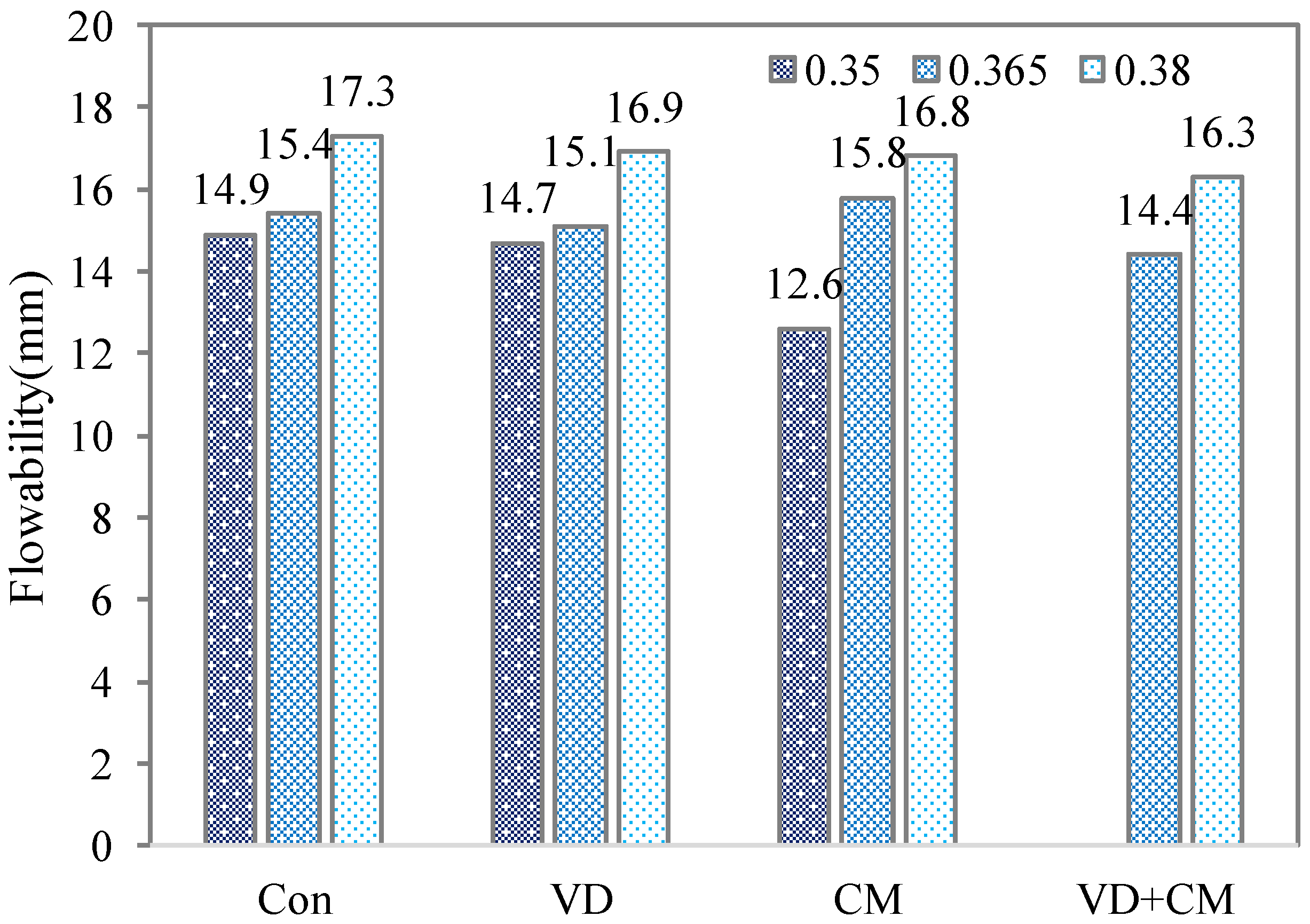
Flowability characterizes the ability of mortar to deform and spread under its own weight or external forces. It directly determines the material’s extrudability and interlayer stacking behavior. The flowability is shown in Figure 2. The results indicate that for specimens with a lower water-to-binder ratio and poorer flowability, CM and VD can effectively reduce the mortar’s flowability. Taking 3DPCM with a water-to-binder ratio of 0.35 as an example, when the mortar mix proportion remains unchanged but the printing process varies, CM and NP reduce its flowability, as detected with the jumping-table method, to 98.7% and 84.6%, respectively. Moreover, when these two processes were applied together, the decrease in flowability became more significant. The flowability was reduced to such an extent that it failed to meet printing requirements; therefore, there is no data for VD + CM for a water-to-binder ratio of 0.35.
Under the water-to-binder ratio of 0.365, the reduction in flowability is less substantial. When only VD is applied, the flowability decreases by 2%. The CM’s flowability is even higher than the control one; this may be due to the experimental randomness. For the condition using a hybrid method of VD and CM, the flowability reduces to 93.5% of the original 3DPCM.
At a water-to-binder ratio of 0.38, the decrease in flowability can also be detected. The combined method of VD + CM has a flowability reduction not exceeding 7%; the separated methods have fewer effects. Furthermore, compared to VD, CM has a more significant impact on the flowability of printed mortar, with its average influence being 138% that of VD. This difference is particularly evident when the flowability is initially low. It can also be concluded that this flowability effect is more pronounced when the initial flowability is inherently low.

3.1.2. Extrudability

The printed specimens were fabricated in a strip-like geometry with four layers, each having a thickness of 10 mm, and a length of 200 mm. For 3DPCM at a water-to-binder ratio of 0.35 with different treatment methods, it can be observed that the printed specimens exhibited a relatively rough surface with numerous pores. Two distinct areas of material deficiency were observed on the 200 mm-long specimen, along with two edge cracks. Under the influence of VD, the specimen surface remained rough and displayed two noticeable cracks. After treatment with CM, the extrudability of the material decreased significantly, resulting in one prominent material breakage zone, two obvious material-deficient depressions on the surface, and substantial edge protrusions and depressions. When these two processes were applied together, the printer failed to print the mortar.
At a water-to-binder ratio of 0.365, the surface of the strip specimen printed with untreated mortar appeared smooth compared to that with the ratio of 0.35, with reduced porosity and no noticeable cracks, as shown in Figure 3. When VD was applied, the specimen surface maintained a similar level of flatness. However, after CM, surface cracks and pores increased noticeably, and one significant protrusion and depression appeared along the edge. When both VD and CM were applied, the extrudability of the material gradually deteriorated, surface roughness increased, porosity became more pronounced, and two mortar deficient depressions were observed in the bottom layer.
At a water-to-binder ratio of 0.38, slight material dripping was observed when the untreated mortar was loaded into the printing tank prior to printing. This phenomenon disappeared after CM was activated. These results indicate that CM and VD can improve the extrudability of mortars with higher flowability, but for mortars with poorer flowability and lower water-to-binder ratios, the same treatments lead to a reduction in extrudability.

3.1.3. Buildability

Under the condition of a 0.38 water-to-binder ratio, the printed specimens exhibited significant slump (see Figure 4). When using a nozzle diameter of 20 mm, the maximum width of the bottom layer reached 27.2 mm, far exceeding the standard printing dimensional requirements, indicating severe slump deformation. When VD and CM were applied individually, the deformation was reduced; however, the interlayer squeezing can still be found. Under the combined application of both processes, the deformation decreased so that the widths of four layers are almost similar (also see Figure 4).
For specimens with a water-to-binder ratio of 0.365, more substantial improvements in deformation control were observed. CM alone reduced deformation in the bottom layer by 5.1%, while VD reduced it by 4.9%, if measuring the width of each layer. The synergistic effect of both techniques resulted in a deformation reduction of 5.5%.
In contrast, at the water-to-binder ratio of 0.35, the effects of both VD and CM on deformation were limited, showing no significant improvement. It was also because the 3DPCM of the water-to-binder ratio of 0.35 had a proper printability already. The results demonstrate that for mortar systems with higher flowability, both VD and CM can effectively enhance the shape retention performance of printed elements by accelerating the hardening process after extrusion.

3.2. Mechanical Properties

3.2.1. Compressive Strength

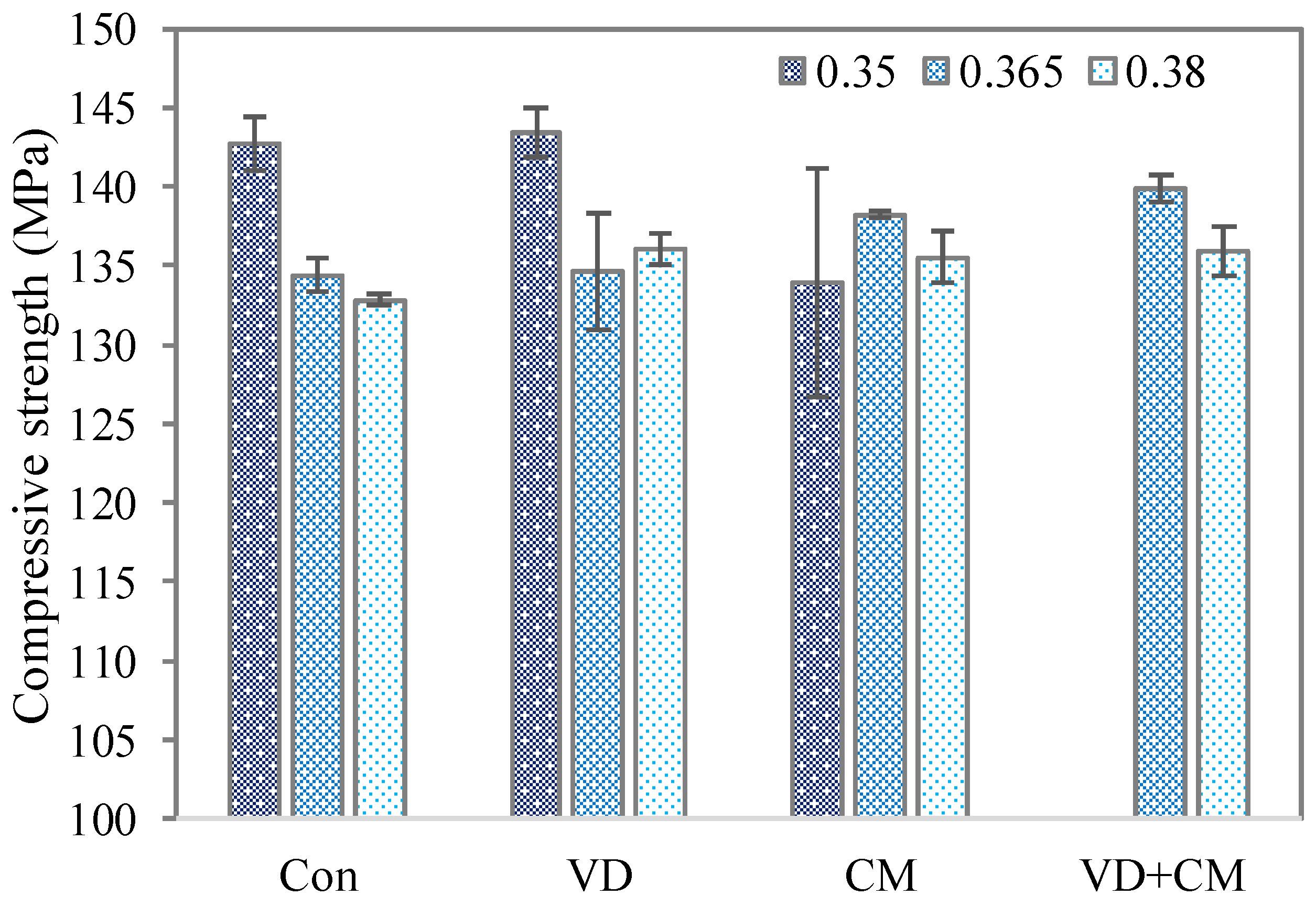
Based on the analysis of cube compressive strength from different mix proportions obtained through mortar cube compression tests (Figure 5), it is evident that VD has no significant impact on the compressive strength of mortar cubes. Neither VD nor CM resulted in a reduction in cube compressive strength. Specifically, for mortar with a water-to-binder ratio of 0.35, CM slightly increased the compressive strength, but the average improvement was only 3.0%. It has been reported that the CM method is capable of producing nanoscale calcium carbonate (CaCO3) particles. This approach promotes further polymerization of hydration products, leading to the formation of a dense layer on the surface of cement clinker. The enhanced generation of hydration and carbonation products extends the induction period of cement hydration, while the presence of an appropriate amount of nanoscale CaCO3 particles accelerates the hardening of fresh mortar via a nucleation mechanism, thereby increasing the overall strength of the material [13,24]. The enhancement observed across three test groups was not significant, showing no consistent upward or downward trend. It can be preliminarily inferred that CM has no clear relationship with the strength of printed mortar—it neither enhances nor reduces strength noticeably.
For mortar with a ratio of 0.365, the average strength increase was 4.6% as CM was being used. Some cubes even exhibited a decrease in strength. Similarly, with a ratio of 0.38, CM resulted in an average strength increase of only 4.1%. Thus, it can be concluded that both CM and VD can improve mortar strength, but the increase remains within 5%.
To simulate the layer-by-layer deposition characteristic of 3D printing, the specimens in this experiment were cast without vibration compaction, adopting instead a layered casting method. This led to defects such as broken corners and air bubbles in some specimens during demolding. Strength calculations were adjusted accordingly based on the specific cut section areas measured for each specimen.

3.2.2. Interfacial Bonding Strength

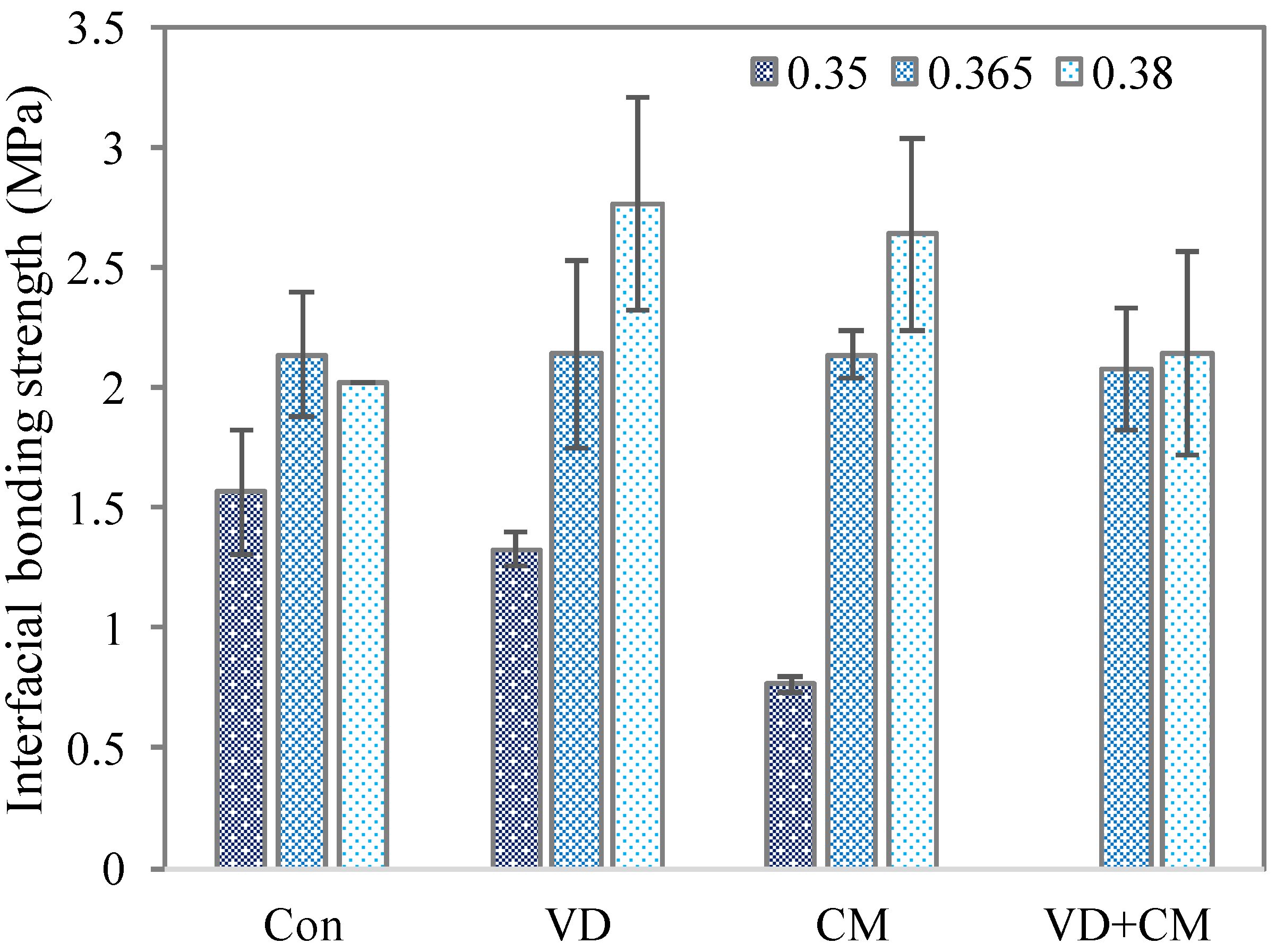
For mortar with a ratio of 0.35, the original interlayer bonding strength is lower than the other groups of higher water-to-binder ratios. In addition, both CM and VD reduce mortar flowability and accelerate hardening, leading to premature setting before full interlayer bonding can occur. Hence, a general decline in interlayer bond strength was observed (see Figure 6). Between the two processes of CM and VD, CM had a more pronounced effect on printability. Two methods both affected the interfacial bonding strength.
For specimens with ratios of 0.365 and 0.38, the slump on both sides was cut off, making the interfaces between the second and third layers, and the third and fourth layers, unidentifiable. Therefore, only the bond strength of the first interface was analyzed.
For mortar with a ratio of 0.365, VD had almost no significant effects on the interlayer bonding strength of the first layer. CM also showed an insignificant improvement of 7.9%. When both processes were applied together, strength decreased by 3.6%. This suggests that both processes can enhance interlayer bonding in mortars with a 0.365 ratio, thereby improving buildability. However, when applied together—consistent with findings for the 0.35 ratio—overly rapid hardening prevented sufficient interlayer bonding.
For more fluid mortar with a ratio of 0.38, both VD and CM markedly improved interlayer strength by 43.2% and 41.0%, respectively. When both techniques were combined, strength returned to 89.0% of the control value. This is because the mortar layers become too dry to contact each other.
This indicates that the combined use of VD and CM accelerates hardening excessively, which is detrimental to interlayer bonding. However, when applied individually, either process can enhance interlayer bond strength and improve the buildability of 3D-printed mortar, provided that the water-to-binder ratio is not lower than 0.35. Below this ratio, both processes may directly reduce interlayer bond strength.
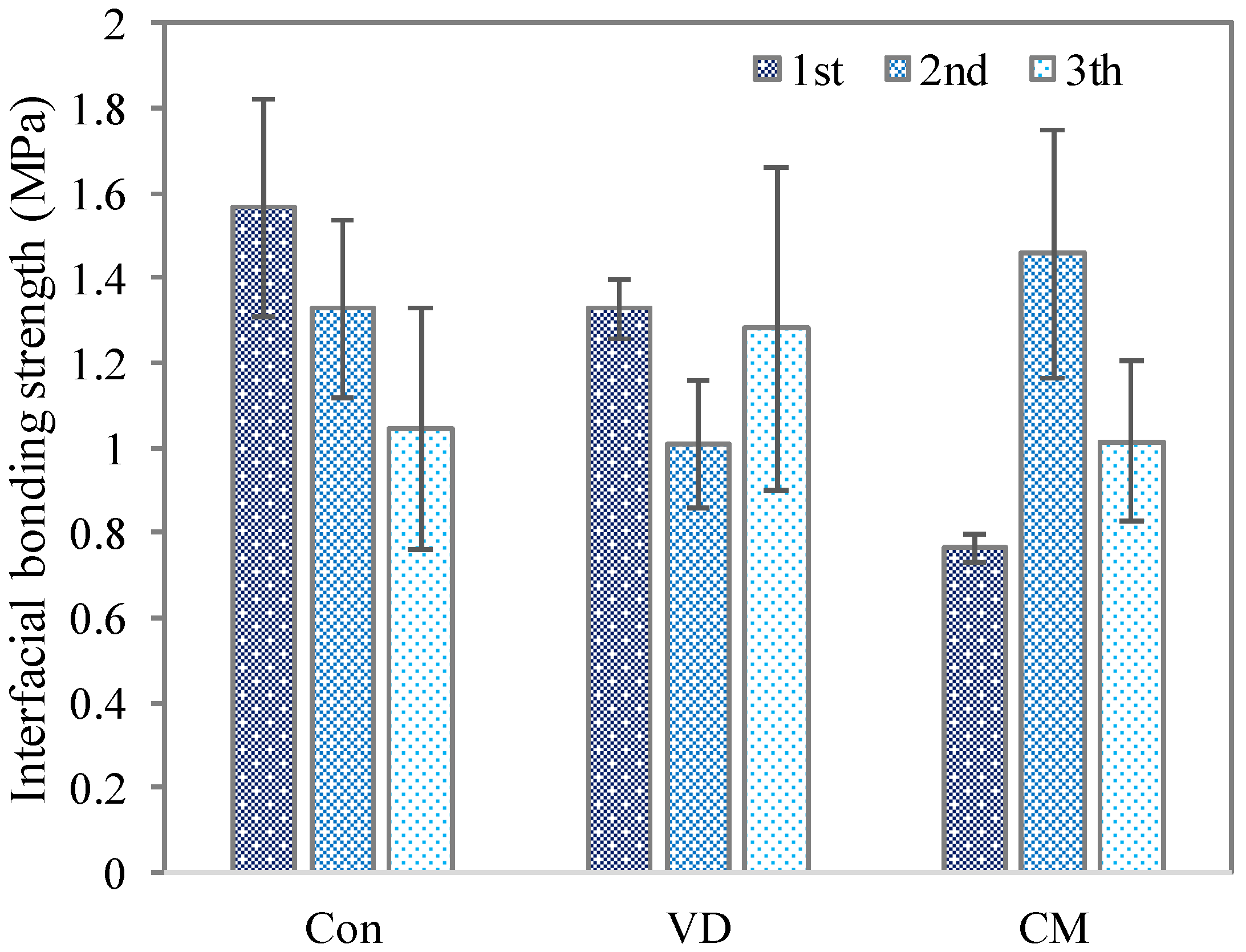
For the ratio 0.35, three inter-layer interfaces can be tested to obtain the interfacial bonding strengths, which are shown in Figure 7. The first layer is the lowest interface, the second is the middle, and the third is the upper. Due to the squeezing effect of upper layers on lower ones, the interlayer bonding strength of upper layers is generally weaker than that of lower layers [25]. The figure indicates that for the first layer of mortar with a ratio of 0.35, CM reduced the interlayer bond strength by 52.1%, while VD caused a reduction of 11.0%. In the second layer, CM increased interlayer bond strength by 9.6%; however, VD decreased it by 25%. In the third layer, CM decreased bond strength by 3.3%, while VD increased it by 22%.

3.3. Microstructure

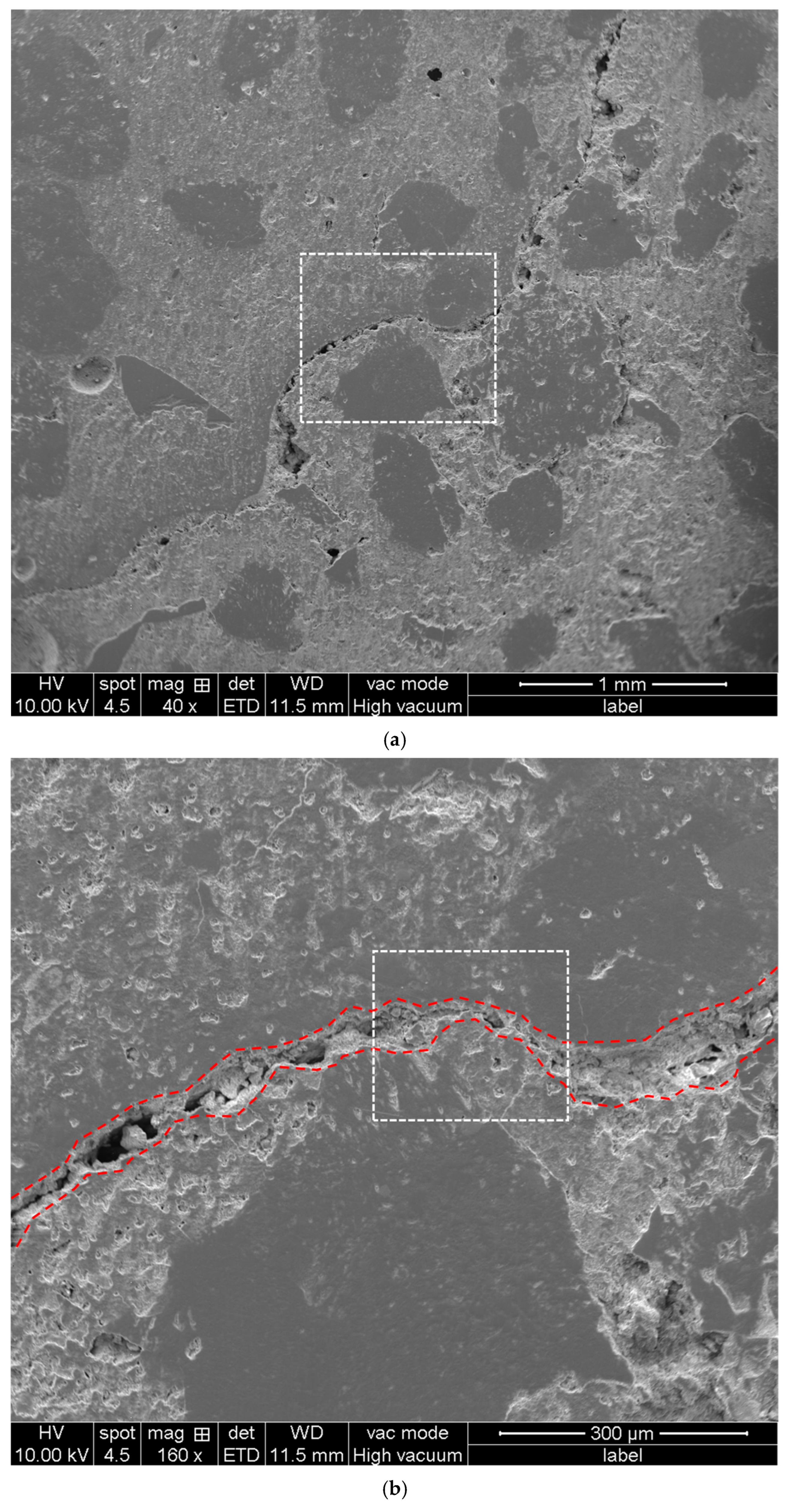
The SEM specimen was selected from a location encompassing the interfacial transition zone (ITZ) between two printed layers, as shown in Figure 8a. The ITZ is clearly observable. Particularly in the central region, the interface is seen to curve around a sand particle, deviating from a straight path.
For 3DPCM with a lower water-to-binder ratio, the rough surface of the underlying layer allows sand particles to penetrate more easily, which is beneficial for enhancing the interfacial bonding strength. However, if the 3DPM is too dry, the bond between the two layers weakens, resulting in a weaker ITZ of the hardened paste. The interfacial bond strength is, therefore, determined by a balance between these two competing factors. Consequently, the aforementioned study found that the VD and CM methods had a positive effect on the interfacial bonding of 3DPCM with a higher water-to-binder ratio but a detrimental effect on those with a lower water-to-binder ratio [26].
A higher magnification image of the central part of Figure 8a, as shown with the white dot rectangle, presented in Figure 8b, reveals pores within the ITZ. The ITZ is illustrated with red dot lines in Figure 8b. These pores in ITZ are likely caused by air entrapped during the printing process that could not escape in time. In subsequent cement hydration, the hydration products are insufficient to fill these voids, which further explains why the interface between layers is a weak point in 3DPCM [27].
Figure 8c, a further magnification from the central part of Figure 8b, shows that at a greater depth along the interface, the hydrated paste exhibits good contact and bonding. This indicates that the quality of the ITZ varies along the printing direction, with some areas well-bonded and others containing defects like pores. As indicated by the red dashed line in Figure 8c, the ITZ boundary was identified at the polished surface. The width of the ITZ was measured to be approximately 20 μm at its narrowest point and 50 μm at its widest.
Even at the higher magnification in Figure 8d, a distinct interface remains visible. The morphology of hydration crystals within the interface can be observed, suggesting that crystals in the pores can grow freely and interlock, thereby contributing to the bond strength of the ITZ [28]. Additionally, a microcrack was observed in this area. This crack likely formed due to volumetric shrinkage during hydration of the paste, which is another factor contributing to the weakness of the interfacial transition zone [29].

4. Conclusions

This study investigates the effects of two methods, CM and VD, on the buildability of three types of mortar mixes. Based on the experimental results, the following conclusions can be drawn:
(1) For mortar with a low water-cement ratio, both CM and VD can significantly reduce its rheological properties. For mortar with a high water-cement ratio, the rheological properties can also be reduced by less than 7%, though the effect is less pronounced.
(2) For mortar with a high water-cement ratio, CM or n VD can considerably improve its printability, enabling mortar with high fluidity to exhibit good printability.
(3) For mortar with a high water-cement ratio, CM or VD can significantly accelerate the hardening process, thereby markedly enhancing the shape retention of printed specimens. Additionally, the compressive strength can be enhanced by 4.1–4.6%.
(4) Both CM and VD can increase the interlayer bonding strength of more fluid mortar. However, when applied simultaneously, they cause excessively rapid hardening, which may reduce interlayer strength.
(5) This study focuses on the effects of CM and VD on the buildability of 3D printed mortar, but several issues remain to be further explored and investigated. To uncover more universal patterns, it is necessary to conduct tests on the buildability of mortar under a wider range of mix proportions. For the CM technique, parameters such as mixing speed, CO2 flow rate, and injection location could be adjusted to explore their optimizing effects on mortar buildability.

Author Contributions

Conceptualization, Q.S. and G.Z.; methodology, Q.S.; validation, Q.S. and G.Z.; investigation, Q.S. and G.Z.; resources, Q.S. and Q.L.; data curation, Q.S. and G.Z.; writing—original draft preparation, Q.S. and G.Z.; writing—review and editing, Q.L. and H.B.; visualization, Q.S. and G.Z.; supervision, H.B.; project administration, Q.S. and H.B.; All authors have read and agreed to the published version of the manuscript.

Funding

This research received no external funding.

Data Availability Statement

The data presented in this study are available on request from the corresponding author due to the ongoing investigation project.

Conflicts of Interest

The authors declare no conflicts of interest.

Abbreviations

The following abbreviations are used in this manuscript:
3DPCM3D-printed construction mortar
VDVacuum dewater
CMCarbonation mixing
RFARecycled fine aggregate
SFSilica fume
SPSuperplasticizer
NCNano-clay
HPMCHydroxypropyl methyl cellulose
SGSodium gluconate
DFDefoamer
ITZInterfacial transition zone

References

  1. Beltrami, M.; Orzes, G.; Sarkis, J.; Sartor, M. Industry 4.0 and sustainability: Towards conceptualization and theory. J. Clean. Prod. 2021, 312, 127733. [Google Scholar] [CrossRef]
  2. Ahmed, G.H. A review of “3D concrete printing”: Materials and process characterization, economic considerations and environmental sustainability. J. Build. Eng. 2023, 66, 105863. [Google Scholar] [CrossRef]
  3. Chen, K.; Liu, Q.; Chen, B.; Zhang, S.; Ferrara, L.; Li, W. Effect of raw materials on the performance of 3D printing geopolymer: A review. J. Build. Eng. 2024, 84, 108501. [Google Scholar] [CrossRef]
  4. Robayo-Salazar, R.; Mejía de Gutiérrez, R.; Villaquirán-Caicedo, M.A.; Delvasto Arjona, S. 3D printing with cementitious materials: Challenges and opportunities for the construction sector. Autom. Constr. 2023, 146, 104693. [Google Scholar] [CrossRef]
  5. Batikha, M.; Jotangia, R.; Baaj, M.Y.; Mousleh, I. 3D concrete printing for sustainable and economical construction: A comparative study. Autom. Constr. 2022, 134, 104087. [Google Scholar] [CrossRef]
  6. Ma, G.; Salman, N.M.; Wang, L.; Wang, F. A novel additive mortar leveraging internal curing for enhancing interlayer bonding of cementitious composite for 3D printing. Constr. Build. Mater. 2020, 244, 118305. [Google Scholar] [CrossRef]
  7. Kristombu Baduge, S.; Navaratnam, S.; Abu-Zidan, Y.; McCormack, T.; Nguyen, K.; Mendis, P.; Zhang, G.; Aye, L. Improving Performance of Additive Manufactured (3D Printed) Concrete: A Review on Material Mix Design, Processing, Interlayer Bonding, and Reinforcing Methods. Structures 2021, 29, 1597–1609. [Google Scholar] [CrossRef]
  8. Huang, G.; Pudasainee, D.; Gupta, R.; Liu, W.V. Extending blending proportions of ordinary Portland cement and calcium sulfoaluminate cement blends: Its effects on setting, workability, and strength development. Front. Struct. Civ. Eng. 2021, 15, 1249–1260. [Google Scholar] [CrossRef]
  9. Kumar, A.; Kumar, V.; Joshi, Y.M.; Singh, M.K. Nano-silica based aqueous colloidal gels as eco-friendly thixotropic lubricant. J. Colloid Interface Sci. 2025, 700, 138486. [Google Scholar] [CrossRef]
  10. Wang, Y.; Jiang, Y.; Pan, T.; Yin, K. The Synergistic Effect of Ester-Ether Copolymerization Thixo-Tropic Superplasticizer and Nano-Clay on the Buildability of 3D Printable Cementitious Materials. Materials 2021, 14, 4622. [Google Scholar] [CrossRef]
  11. Zhang, T.; Chen, M.; Wang, Y.; Zhang, M. Roles of carbonated recycled fines and aggregates in hydration, microstructure and mechanical properties of concrete: A critical review. Cem. Concr. Compos. 2023, 138, 104994. [Google Scholar] [CrossRef]
  12. Liang, C.; Pan, B.; Ma, Z.; He, Z.; Duan, Z. Utilization of CO2 curing to enhance the properties of recycled aggregate and prepared concrete: A review. Cem. Concr. Compos. 2020, 105, 103446. [Google Scholar] [CrossRef]
  13. Monkman, S.; Sargam, Y.; Naboka, O.; Lothenbach, B. Early age impacts of CO2 activation on the tricalcium silicate and cement systems. J. CO2 Util. 2022, 65, 102254. [Google Scholar] [CrossRef]
  14. Monkman, S.; Hwang, S.D.; Khayat, K. Rheology modification of flowable mortar with CO2. Cem. Concr. Compos. 2024, 151, 105584. [Google Scholar] [CrossRef]
  15. Monkman, S.; Lee, B.E.J.; Grandfield, K.; MacDonald, M.; Raki, L. The impacts of in-situ carbonate seeding on the early hydration of tricalcium silicate. Cem. Concr. Res. 2020, 136, 106179. [Google Scholar] [CrossRef]
  16. Mehta, P.K.; Monteiro, P.J.M. Concrete: Microstructure, Properties, and Materials, 4th ed.; McGraw-Hill Education: New York, NY, USA, 2014. [Google Scholar]
  17. Dongxu, L.; Xuequan, W. A study on the application of vacuum microwave composite dewatering technnique in concrete engineering. Cem. Concr. Res. 1994, 24, 159–164. [Google Scholar] [CrossRef]
  18. Sancak, E. Effect of Vacuum Dewatering Application on the Chemical Corrosion and Mechanical Properties of Concrete. Asian J. Appl. Sci. 2008, 1, 79–86. [Google Scholar] [CrossRef]
  19. Lim, S.; Buswell, R.A.; Le, T.T.; Austin, S.A.; Gibb, A.G.F.; Thorpe, T. Developments in construction-scale additive manufacturing processes. Autom. Constr. 2012, 21, 262–268. [Google Scholar] [CrossRef]
  20. Shahzad, Q.; Wang, X.; Wang, W.; Wan, Y.; Li, G.; Ren, C.; Mao, Y. Coordinated adjustment and optimization of setting time, flowability, and mechanical strength for construction 3D printing material derived from solid waste. Constr. Build. Mater. 2020, 259, 119854. [Google Scholar] [CrossRef]
  21. Korpa, A.; Trettin, R. The influence of different drying methods on cement paste microstructures as reflected by gas adsorption: Comparison between freeze-drying (F-drying), D-drying, P-drying and oven-drying methods. Cem. Concr. Res. 2006, 36, 634–649. [Google Scholar] [CrossRef]
  22. ASTM C1437-20; Standard Test Method for Flow of Hydraulic Cement Mortar. ASTM International: West Conshohocken, PA, USA, 2020.
  23. Liu, Q.; Cheng, S.; Sun, C.; Chen, K.; Singh, A.; Bai, T.; Bai, Y. Effects of varied building solid wastes, particle sizes and substitution ratios on the performance and impedance spectrum of recycled fine aggregate mortar and the feasibility of developing a prediction method. J. Build. Eng. 2024, 83, 108310. [Google Scholar] [CrossRef]
  24. Liu, Q.; Cheng, A.; Singh, A.; Tam, V.W.Y. Performance enhancement of recycled concrete through carbonation during ready-mix and curing. Constr. Build. Mater. 2025, 458, 139665. [Google Scholar] [CrossRef]
  25. Weng, Y.; Li, M.; Zhang, D.; Tan, M.J.; Qian, S. Investigation of interlayer adhesion of 3D printable cementitious material from the aspect of printing process. Cem. Concr. Res. 2021, 143, 106386. [Google Scholar] [CrossRef]
  26. Yu, K.; McGee, W.; Ng, T.Y.; Zhu, H.; Li, V.C. 3D-printable engineered cementitious composites (3DP-ECC): Fresh and hardened properties. Cem. Concr. Res. 2021, 143, 106388. [Google Scholar] [CrossRef]
  27. Aslani, F.; Dale, R.; Hamidi, F.; Valizadeh, A. Mechanical and shrinkage performance of 3D-printed rubberised engineered cementitious composites. Constr. Build. Mater. 2022, 339, 127665. [Google Scholar] [CrossRef]
  28. Moelich, G.M.; Kruger, J.; Combrinck, R. Modeling the interlayer bond strength of 3D printed concrete with surface moisture. Cem. Concr. Res. 2021, 150, 106559. [Google Scholar] [CrossRef]
  29. Wolfs, R.J.M.; Bos, F.P.; Salet, T.A.M. Hardened properties of 3D printed concrete: The influence of process parameters on interlayer adhesion. Cem. Concr. Res. 2019, 119, 132–140. [Google Scholar] [CrossRef]
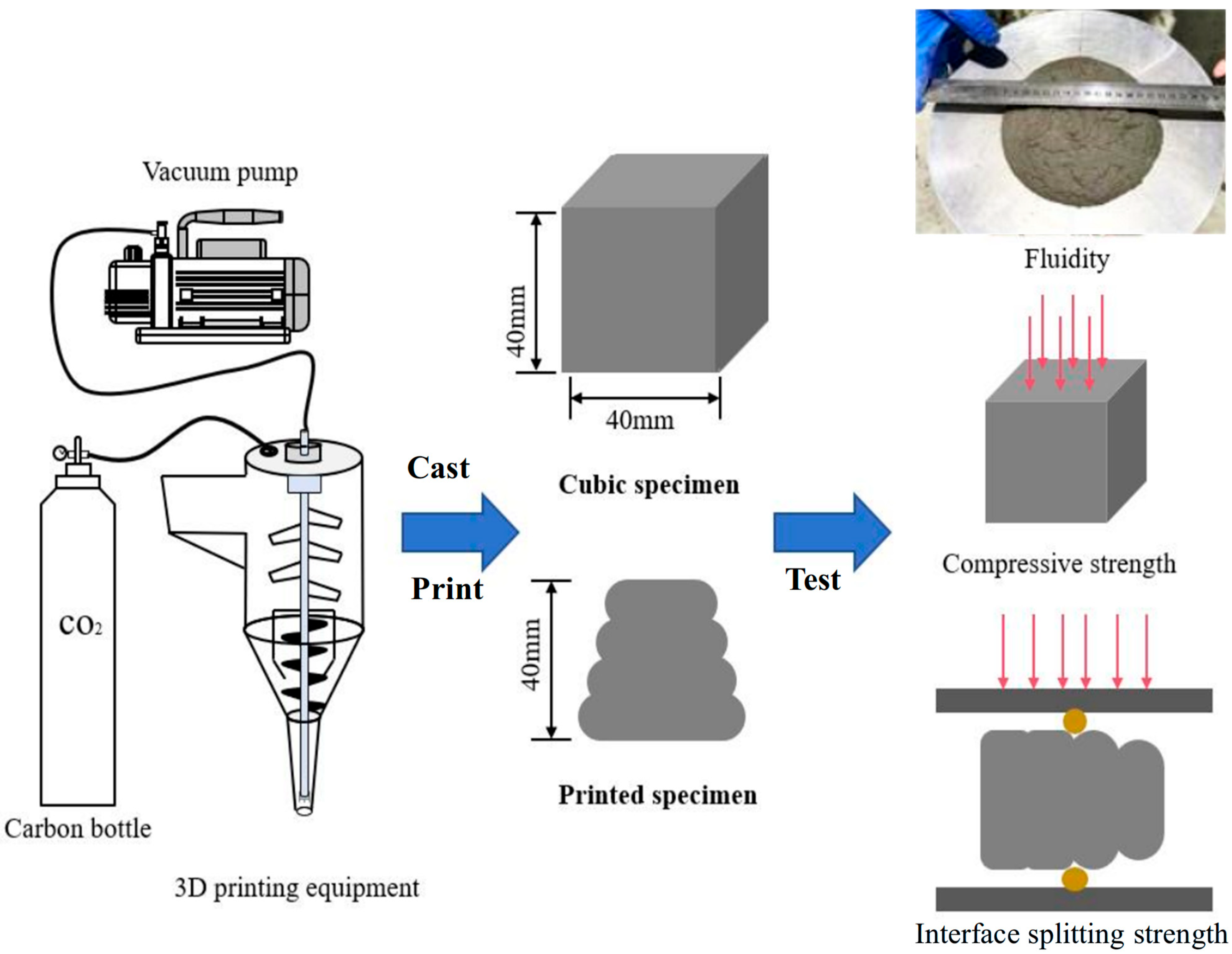
Figure 1. Experimental procedure.
Buildings 15 04036 g001
Figure 2. Flowability.
Buildings 15 04036 g002
Figure 3. Extruded 3DPM (Water-to-binder ratio 0.365, Con represent the control group).
Buildings 15 04036 g003
Figure 4. Cut section of the printed 3DPM (water-to-binder ratio 0.38).
Buildings 15 04036 g004
Figure 5. Compressive strength of cast specimen.
Buildings 15 04036 g005
Figure 6. Interfacial bonding strengths.
Buildings 15 04036 g006
Figure 7. Interfacial bonding strength of different layers (water-to-binder ratio 0.35).
Buildings 15 04036 g007
Figure 8. SEM images: (a) 100 zoom; (b) 500 zoom; (c) 3000 zoom; (d) 10,000 zoom.
Buildings 15 04036 g008aBuildings 15 04036 g008b
Table 1. Chemical composition of cement (W%).
CaoSiO2Fe2O3Al2O3Na2OMgOK2OSO3
63.8020.783.993.570.261.720.753.82
Table 2. Grain size distribution of recycled sand (%).
1.18–0.6 mm0.6–0.3 mm0.3–0.15 mm0.15–0.075 mm<0.075 mm
34.4232.4822.209.500.98
Table 3. Mix proportion (kg/m3).
CementWaterRFASFSPNCHPMCSGDF
10003501000500.551.30.70.5
10003651000500.551.30.70.5
10003801000500.551.30.70.5
Disclaimer/Publisher’s Note: The statements, opinions and data contained in all publications are solely those of the individual author(s) and contributor(s) and not of MDPI and/or the editor(s). MDPI and/or the editor(s) disclaim responsibility for any injury to people or property resulting from any ideas, methods, instructions or products referred to in the content.