Article

Bending Test and FE Analysis of Novel Grouted Plug-in Connection for Prefabricated Assembled Raft Foundation

1
Power China Hubei Electric Engineering Co., Ltd., Wuhan 430040, China
2
School of Civil Engineering and Architecture, Wuhan University of Technology, Wuhan 430070, China
3
State Grid Hubei Zhongchao Construction Management Company, Wuhan 430022, China
*
Author to whom correspondence should be addressed.
Buildings 2025, 15(21), 3931; https://doi.org/10.3390/buildings15213931 (registering DOI)
Submission received: 25 September 2025 / Revised: 26 October 2025 / Accepted: 28 October 2025 / Published: 30 October 2025

Abstract

Research on the development of prefabricated foundations has been quite extensive to date, while studies on prefabricated concrete raft foundations and their connection methods remain relatively scarce. This study proposes a novel type of prefabricated raft foundation and its corresponding grouted plug-in connection. The connection comprises two prefabricated units and achieves connection via steel inserts and grouting in pre-slots, possessing numerous advantages such as convenient construction, fast installation, and high construction quality. To verify the performance of the connection node and the bearing capacity of the foundation, based on the engineering practice of prefabricated raft foundations, this study fabricated a full-scale specimen composed of three prefabricated units of the raft foundation, conducted a stacking load test on it, and carried out finite element analysis afterwards. The main conclusion is that severe flexural failure occurred near the grouted plug-in connection of the prefabricated units when the specimen failed, implying that the node region has sufficient bearing capacity. The ultimate bending moments of the specimen obtained from the experiment and finite element analysis are 736.5 kN·m and 859.5·kN m, respectively, with a difference of 14%, indicating a good agreement between them. Ignoring the effect of the upper steel reinforcements, the calculated section bending capacity of the prefabricated unit is 892.8·kN m; the ultimate bending moment of the test specimen reached 0.83 of the section bending capacity of the prefabricated unit, indicating that the proposed raft foundation and its connection method have good bending bearing capacity.

1. Introduction

Prefabricated concrete structures, leveraging their advantages such as high construction efficiency and a high degree of industrialization, have embraced significant development opportunities and achieved rapid progress in many fields such as residential buildings, public buildings, industrial buildings, and other infrastructures in mainland China. In past decades, prefabricated foundations started replacing traditional cast-in-place ones in many scenarios, due to their benefits of efficient construction, environmental friendliness, and high construction quality. The research, development, and application of pre-cast foundations have formed targeted technical solutions focusing on the core pain points of different engineering scenarios.
Currently, researchers have conducted extensive research on the construction techniques and bearing capacity of prefabricated foundations such as transmission tower and wind turbine foundations. Regarding transmission tower foundations, Shao et al. [1] proposed a segmental prestressed prefabricated foundation, which splits the foundation into prefabricated components such as bottom slabs, steps, and columns, and its integrity is guaranteed through a combination of bolted connections and prestressed tendons; Zhang et al. [2] developed a high uplift-resistant prestressed concrete prefabricated foundation, in which each unit is modularly split and fixed using bolts, grouting, and steel plates; Wang et al. [3] innovatively applied four mature building connection schemes (including post-cast strip U-steel connection and lap connection) to slab foundations; subsequently, the same research team [4] further proposed a new type of prefabricated slab foundation with keyways and pre-embedded “beard tendons”. Experimental and simulation verifications indicated that the combined application of these techniques can significantly improve the crack resistance and flexural capacity, with mechanical properties superior to those of cast-in-place components.
In terms of wind turbine foundations, Li et al. [5] developed a prefabricated assembled foundation for the wind turbine consisting of 16 prefabricated blocks; its integrity is enhanced through the concave-convex shear keys, circumferential prestressed steel strands, and grouting. Wang et al. [6] proposed a new type of prefabricated ribbed foundation composed of fan-shaped double-rib beam units, utilizing shear keys and circumferential prestress to improve the integrity, which significantly reduces material consumption compared with traditional foundations. Zhou et al. [7] developed a steel sleeve–UHPC pile grouting connection for offshore wind turbine foundations, in which components are connected via shear keys and grouting material. Li et al. [8] established a three-dimensional finite element model considering the cyclic effects of soil and grouting material, and conducted modal analysis to provide theoretical support for the optimization of bucket foundations. Additionally, Tian et al. [9] proposed a modular prefabricated spread foundation for substation buildings, which comprises double bottom slab modules and top pedestal modules, with components connected through wet joints and shear keys.
The aforementioned studies focus on optimizing the construction techniques of prefabricated foundations. Through scientific structural splitting and reliable connections, they have proved the advantages of prefabricated foundations in terms of construction efficiency and completed the performance verification and optimization work regarding shear capacity, flexural capacity, failure mode, and structural ductility. In addition, to fully exploit the merits of prefabricated foundations, advanced and reliable joint connection technology remains the core guarantee for the integrity and mechanical properties of prefabricated structures. In addition to the application of composite connection techniques involving steel bars, bolts, and other components [1,2,5,6] and the use of post-cast UHPC or grouting connections [2,3,4,7,9], various new connection technologies continue to emerge.
Pul. et al. [10] proposed a monolithic-like steel plate anchorage connection technology, which uses high-strength bolts to connect column end plates with foundation panels, and directly anchors column longitudinal bars to the end plates. Zhou et al. [11] developed a UHPC–steel bar lap connection, employing prefabricated UHPC shells to fulfill supporting and formwork functions, while column longitudinal bars and foundation anchor bars are lapped through UHPC. Fan et al. [12] proposed two connection technologies: grouted sleeves and grouted corrugated pipes. Liu et al. [13] put forward a corrugated steel pipe socket connection, which transfers shear force through the connection between prefabricated corrugated steel pipe concrete columns and foundation-embedded corrugated steel pipes using concrete or UHPC. Cao et al. [14] proposed a connection using a reinforced concrete outer cladding constrained by steel pipes. For this connection, concrete-filled steel tube columns are not embedded into the foundation; instead, they are connected at the column base via shear studs and anchor bars, with the steel pipe constraint (from the outer cladding) serving as supplementary support. Cogurcu et al. [15] developed a column base section-enlarged anchorage connection, which enlarges the column base section and achieves connection using pre-embedded threaded anchorage bars and early-strength high-strength concrete. Qi et al. [16] proposed a new technology for wind turbine foundations featuring shear connectors with a constrained structure—specifically, shear connectors with such a constrained structure are welded onto the foundation pipe of the wind turbine. The constrained structure enhances the interface stiffness as well as the effect of force transmission and diffusion, which not only enables effective connection between the foundation pipe and the concrete foundation but also improves the embedded stiffness and durability of the foundation. Chen et al. [17] put forward an assembled bamboo–lightweight aggregate concrete composite structure connection with perforated steel plate connectors; this connection enables the connection of prefabricated lightweight aggregate concrete blocks using grout and through rebars. It eliminates the need for on-site formwork erection and steel bar binding, thereby achieving rapid assembly and enhancing the interfacial shear performance. Di et al. [18] designed bamboo scrimber beam–column joints connected to concrete joints embedded with steel reinforcing bars, proposed a rigid connection coefficient to quantitatively evaluate the degree of joint rigidity, and provided support for the seismic design and high-rise development of bamboo and timber structures. Xiong et al. [19] developed a prefabricated prestressed concrete frame beam–column external joint with a UHPC connection, where UHPC is poured in the core area of the joint to reduce the amount of stirrups and shorten the anchorage length of longitudinal bars. Zhang et al. [20] and Xu et al. [21] proposed a concrete-encased CFST column–cap beam sleeve joint; CFST columns are inserted into the prefabricated sleeve holes of capping beams, and the gaps between the columns and the sleeve holes are grouted with UHPC. Shear studs are installed on the surface of the CFST to enhance the bonding performance with concrete. Leveraging the high fluidity and high strength of UHPC, the interfacial shear resistance and grouting compactness are improved; meanwhile, the externally wrapped concrete can also enhance the corrosion resistance of the CFST. Bai et al. [22] put forward a double-layer grouting connection, in which inner and outer sleeves of upper and lower prefabricated columns are combined with staggered shear keys and then connected with grouting material. Zhu et al. [23] proposed a UHPC double connection, in which segments are lapped via UHPC wet joints, and the lower segment is connected to the foundation using UHPC grouted corrugated pipes. Yan et al. [24] focused on pre-cast concrete beam–column connections with grout sleeves, investigated the seismic performance of such connections (including failure modes and skeleton curves), and analyzed the influence of parameters like column-to-beam strength ratio, column axial compression ratio, and column assembly height. Qu et al. [25] developed an “inner tube-flange-grouting” connection, achieving integral connection through the flange connection of upper and lower columns, intermediate connectors, and pressure grouting material. Li et al. [26] proposed rabbeted grouting splicing (RGS) joints for prefabricated bottom slabs, conducted three-point bending static tests on prefabricated bottom slabs with RGS joints and cast-in-place bottom slabs, and explored the influence of rabbets and joint forms on component performance.
Beyond the domains discussed above, scholars have also conducted research on the joints of prefabricated components. For instance, Wu et al. [27] put forward a split-type prefabricated box culvert, realizing assembly via cylindrical pins, mortise–tenon joints, and spigot-and-socket joints. Zhao et al. [28] proposed an analytical method considering the shear behavior of composite joints and a modified formula for calculating shear-bearing capacity of a segmentally prefabricated composite box girder with corrugated steel webs, which comprehensively accounts for the shear contributions of concrete connectors, friction, bonding layers, and corrugated steel webs.
It is evident that current research on the connection methods and performance of joints primarily focuses on column–foundation joints and beam–column joints. These studies utilize materials such as sleeves and UHPC to connect prefabricated component joints, thereby meeting service requirements including shear capacity and durability. Due to the structural characteristics of raft foundations, while the performance of these advanced connection methods can meet their service requirements, connection methods like sleeve connections are not conducive to on-site construction. Moreover, the efficiency of sleeve grouting is relatively low, which fails to demonstrate the advantages of prefabricated raft foundations—and this constitutes the second limitation of current research. The development of prefabricated raft foundations and their corresponding connection methods is a crucial aspect of electric power construction. The research, development, and promotion of prefabricated foundations for this equipment are of great significance in the process of transforming substations towards greenization and modularization.
To address this research gap, this paper innovatively proposes a modular assembled raft foundation for HGIS equipment composed of prefabricated units. Furthermore, by integrating existing joint connection technologies, it presents a new connection method suitable for raft foundations, which utilizes steel plates and grouting material. Based on an engineering practice, a full-scale specimen consisting of three prefabricated units for raft foundation (with all components connected via inserting steel plates and grouting) was designed, and a full-scale flexural test was conducted to obtain the flexural bearing capacity and failure mode of the specimen. Subsequently, finite element analysis (FEA) was carried out using ABAQUS-2020 software. Finally, a comprehensive comparison was made between the results obtained from the experimental test and FEA.

2. Testing Specimen

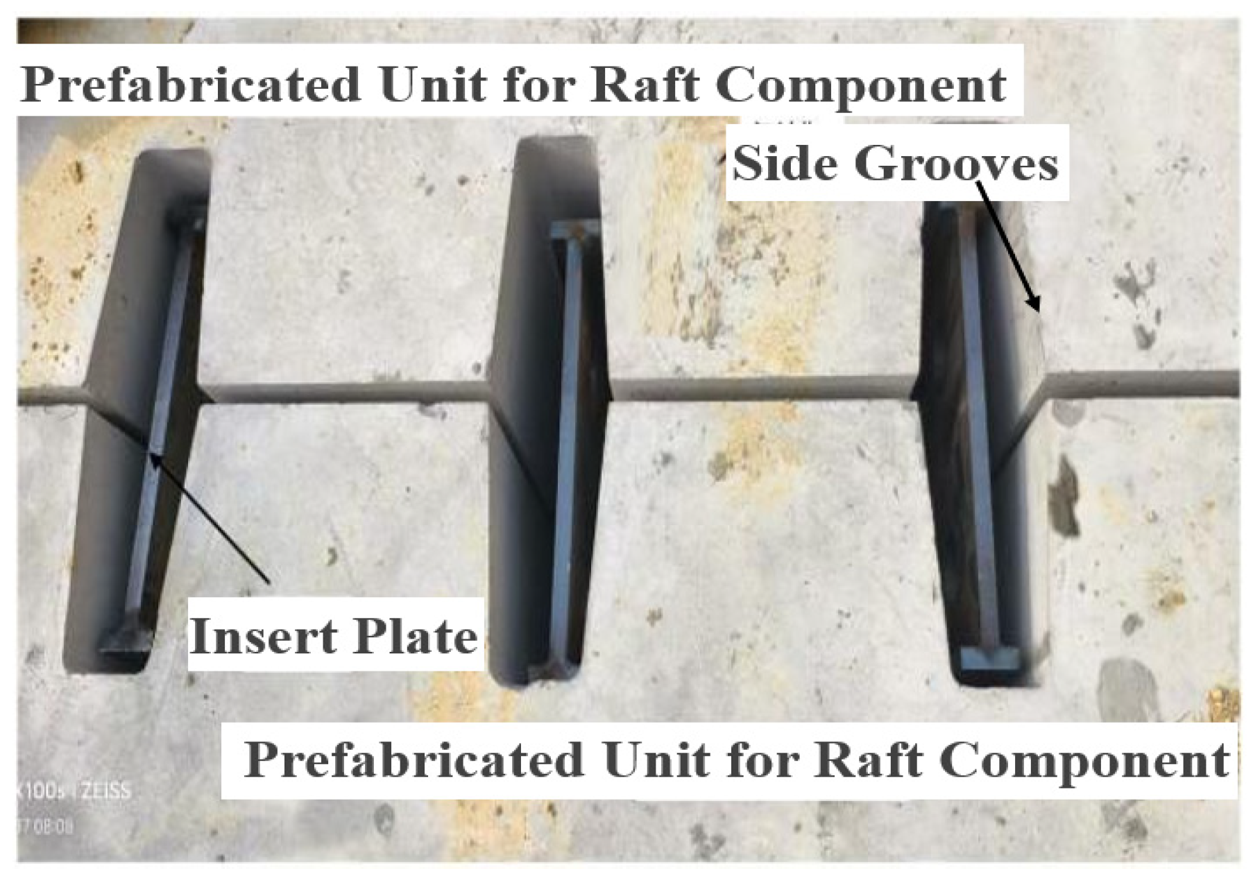
As previously described, the modular assembled raft foundation studied in this paper consists of multiple prefabricated units. The prefabricated unit is shown in Figure 1 and it has end grooves at both ends, with bolt holes symmetrically arranged on two sides of the grooves to facilitate splicing between two units in the corresponding direction. Along the other direction, side grooves are spaced at 300 mm intervals. After steel plates are placed inside the side grooves of two prefabricated units, as shown in Figure 2, grout will be applied. Then, two adjacent prefabricated units can be connected. It should be noted that before grouting, the grooves of the prefabricated units will be subjected to surface roughening treatment to ensure the bonding performance between the two.
To investigate the flexural stiffness and bending bearing capacity of the grouted plug-in connection between two prefabricated units for raft foundation, this paper conducts flexural test and finite element (FE) analysis on a full-scale specimen, whose prototype is from a typical prefabricated raft foundation for hybrid gas insulated switchgear (HGIS) equipment.
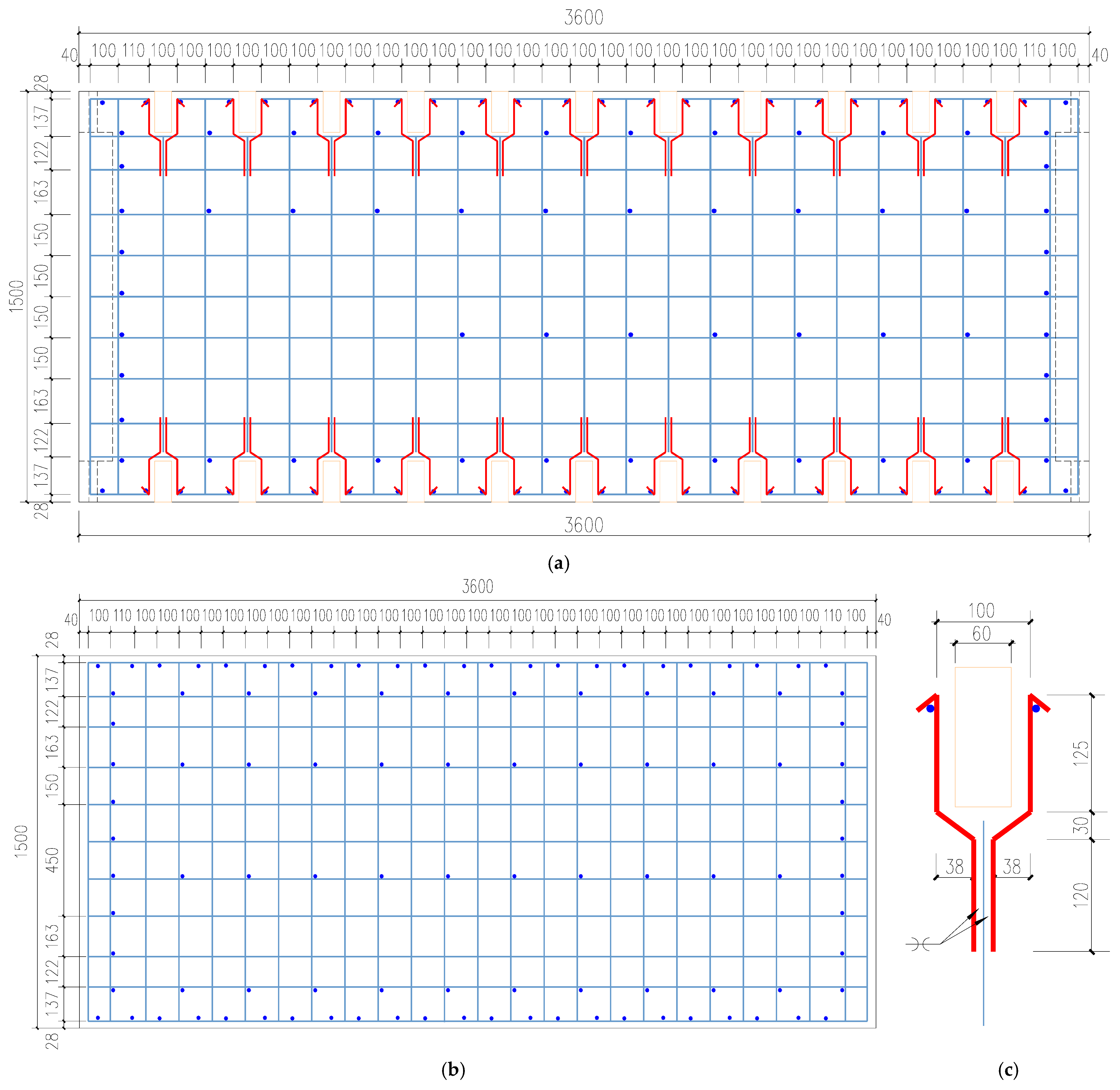
The full-scale flexural test specimen consists of three identical prefabricated units. The dimensions of the prefabricated unit are 3600 × 1500 × 600 mm (length × width × height), which are designed based on engineering practice and adopt the commonly used “300 mm module” to meet the applicability for assembly and installation of raft foundations of different sizes. HRB400 steel reinforcement with 14 mm diameter and C40 normal concrete are used for the specimen. Along both sides, side grooves are spaced at 300 mm intervals, and hence there are 11 grooves per side.
Figure 3a–c show the reinforcement layout of the entire specimen. Figure 3a displays the upper-layer reinforcement arrangement, where steel bars are spaced at 150 mm in both transverse and longitudinal directions. To reinforce the side groove region, additional rebars were placed adjacent to the grooves as detailed in Figure 3b. The lower-layer reinforcement configuration (Figure 3c) adopted identical steel grade, diameter, and spacing as the upper layer.
The side groove features a trapezoidal cross-section, and two 30 mm-diameter bolt holes which accommodate temporary connections using M24 bolts between components are fabricated. The positions and dimensions of grooves are shown in Figure 4.
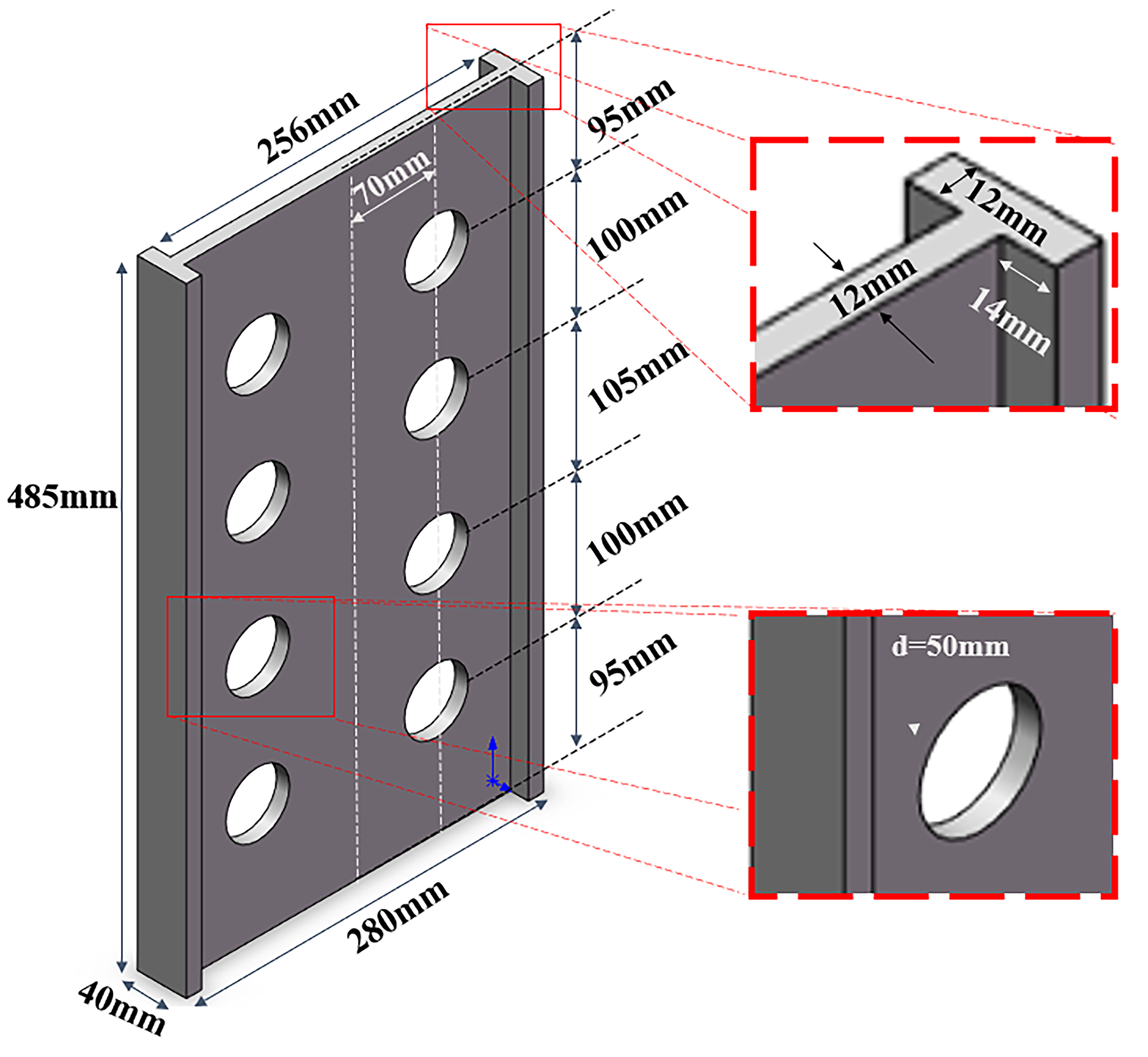
The steel plates inserted into the side grooves are fabricated using 12 mm-thick Q235B steel, forming a perforated I-shaped cross-section. Dimensions of the inserted steel plates are shown in Figure 5. Side grooves were grouted to assemble the specimen in the connection stage.
The full-scale flexural test specimen is formed by assembling three aforementioned prefabricated units via inserted steel plates and grouting. Before assembly, the prefabricated units were cured for 28 days at the prefabrication factory under standard conditions (a temperature of 20 °C and a humidity of 95%); and after the joint casting, the high-strength grouting material was also cured for 7 days under conditions of a temperature of 10~18 °C and a humidity of more than 90%.

3. Flexural Testing Procedure

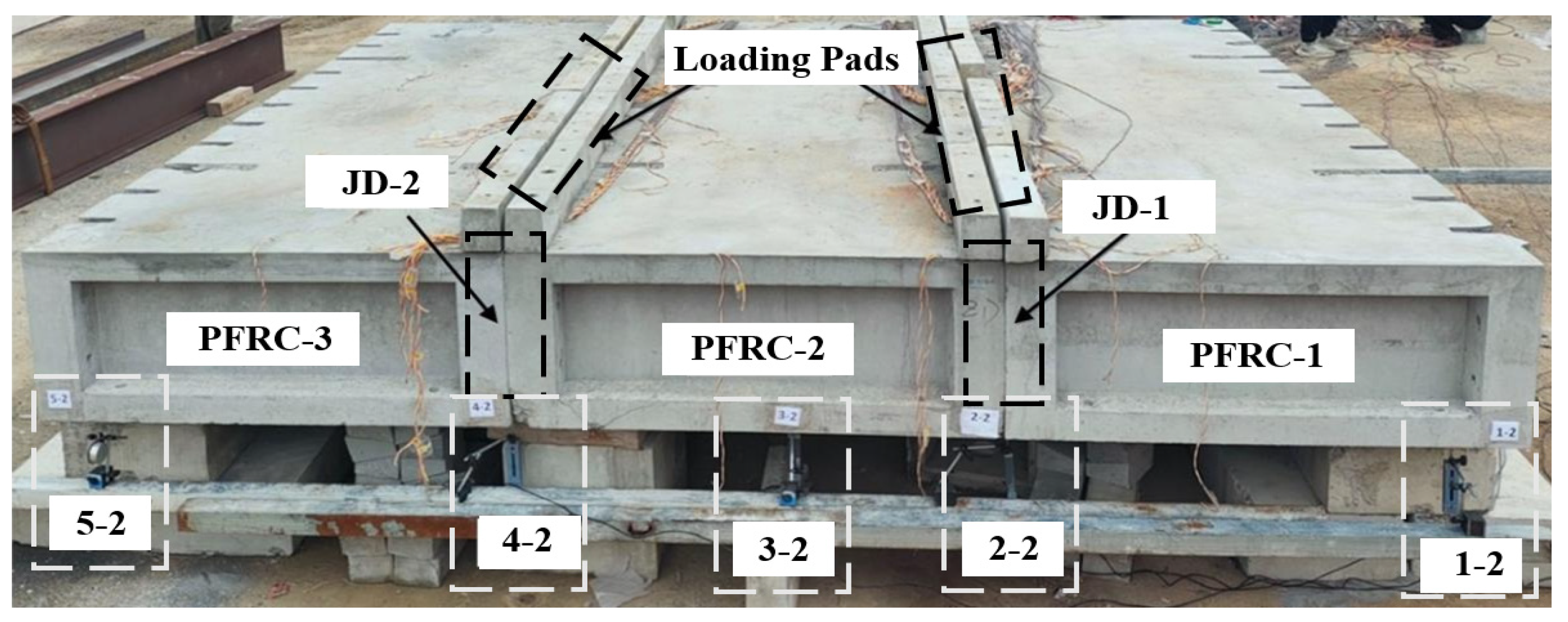
As previously described, the flexural test specimen for the prefabricated raft foundation consists of three prefabricated units, as shown in Figure 6a,b. In Figure 6a, three prefabricated units are designated PFRC-1, PFRC-2, and PFRC-3 and two connections at the interfaces between adjacent prefabricated units are named JD1 and JD2, respectively. The specimen was simply supported at both ends as shown in Figure 6b, where each support comprises three 3100 × 500 × 250 mm and six 500 × 180 × 140 mm prefabricated blocks stacked on cast-in-situ concrete floor slabs.
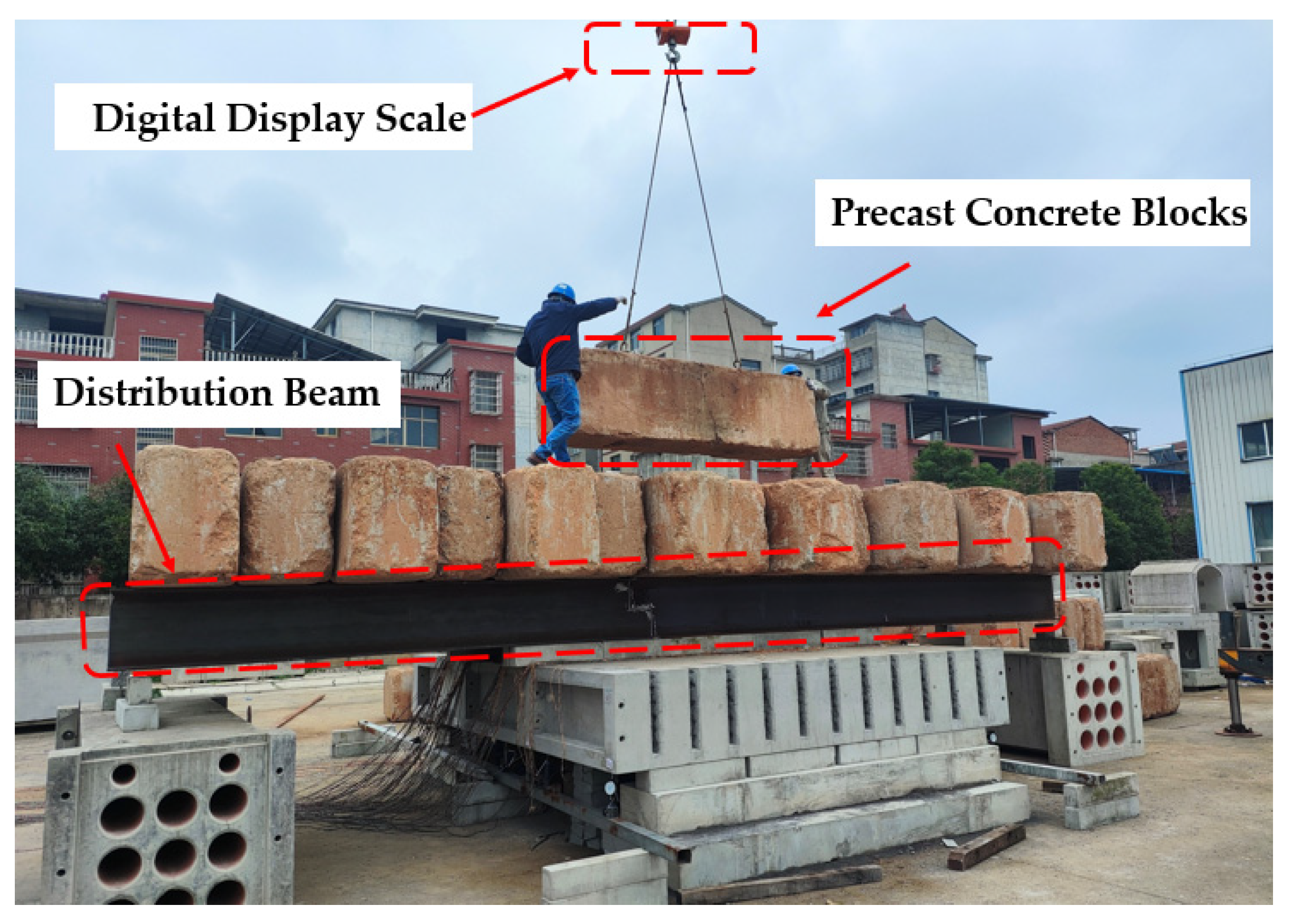
To investigate the specimen’s flexural bearing capacity and failure mode, two concentrated line-loadings were applied. The testing procedures were as follows: firstly, two 500 × 180 × 140 mm concrete prefabricated blocks were placed at both sides of JD1 and JD2; secondly, two 9 m (length) hot-rolled H-beams (H500 × 200 × 10 × 14 mm; weight 0.75 ton) acting as distribution beams were placed over the concrete blocks at JD1 and JD2 connections; finally, pre-cast concrete blocks (weight of each is about 3 tons) were continuously stacked on the two H-beams to apply the concentrated line-loading to the flexural specimen. During loading, the hook of the crane was first connected to a digital display scale before hoisting (Shanghai Yousheng Weighing Apparatus Co., Ltd., Shanghai, China), to ensure the actual weight of each loading block was clear. Subsequently, the loading blocks were placed centrally on the loading beam to ensure the uniform application of the load, as shown in Figure 7. Prior to loading, steel angle bracings were welded between the two H-beams to prevent potential out-of-plane instability during testing. Table 1 provides the loading case numbers, incremental loads, and total load magnitudes.
During the flexural testing, vertical deformations at critical locations were measured under each loading increment to build the load–displacement curve.
Figure 8 illustrates the arrangement and numbering of all displacement gauges for the flexural testing specimen (Jiangsu Donghua Test Technology Co., Ltd., Taizhou, China). Displacement gauges 1-1 and 5-1 measure vertical displacements at the front-side of the supports while 1-2 and 5-2 monitor the vertical displacements at the rear-side of the supports. Displacement gauges 2-1 and 4-1 record vertical displacements at the joint locations in the front while 2-2 and 4-2 track the joint displacements in the back. Displacement gauges 3-1 and 3-2 measure mid-span vertical displacements at two sides of the specimen. To assess opening development at the lower connection seams of JD-1 and JD-2, displacement gauges 6-1 and 6-2 were horizontally mounted between two prefabricated units across the seam. Figure 9 shows the actual installation of the displacement gauges in the back of the specimen.
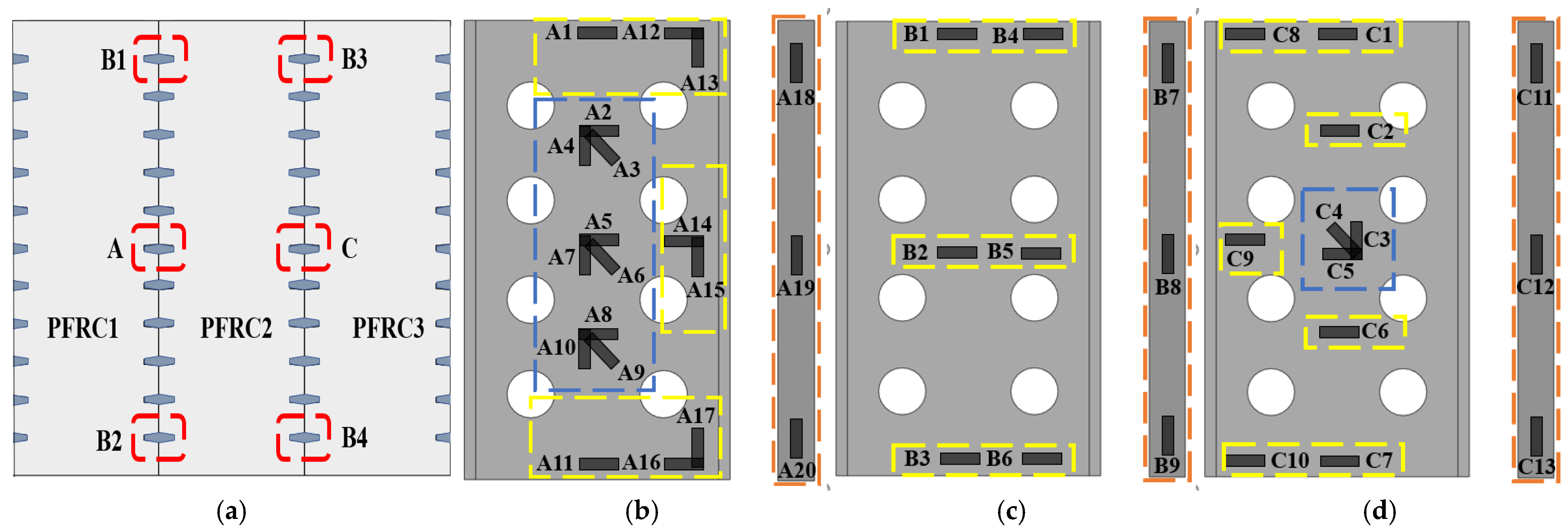
To measure the stress variations in the specimen under each loading increment, strain gauges (Taizhou Huangyan Chengli Engineering Sensor Factory, Taizhou, China) were attached to critical locations on the rebars, the concrete surface of the prefabricated unit, and I-shaped inserted steel plates. Figure 10 illustrates the strain gauge arrangement on the I-shaped inserted steel plates. Specifically, Figure 10a presents the distribution of I-shaped inserted steel plates equipped with strain gauges, where these plates are categorized into three types: Type A, Type B, and Type C. Figure 10b–d detail the strain gauge arrangements on each type of plate, respectively. The strain gauges on Type A and Type C plates include horizontal strain gauges at the upper and lower ends, as well as strain rosettes oriented at 45° to each other in the middle. In contrast, the strain gauges on Type B plates are primarily arranged in the horizontal direction. These strain gauges are used to monitor the changes in the normal stress and shear stress of the I-shaped inserted steel plates.

4. Experimental Observations and Material Property Test Results

4.1. Material Property Test Results

Materials used for the specimen includes the steel reinforcement, inserted steel plates, normal C40 concrete, and the high-strength grout. In accordance with the relevant standards [29,30], each of them was tested to obtain the corresponding mechanical properties, which are provided in Table 2, Table 3, Table 4, Table 5 and Table 6.

4.2. Experimental Observations

The specimen remained in the elastic stage with no visible signs of damage observed until the loading case JZ-4.
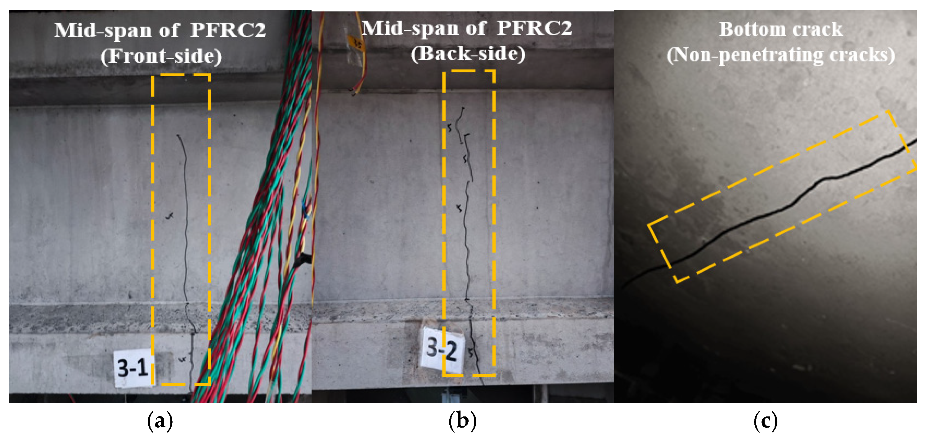
Upon completion of loading case JZ-5 (748.7 kN), concrete cracking occurred at the mid-span of PFRC-2. Cracks with length of 883 and 585 mm were observed in the front-side and back-side of the specimen as shown in Figure 11a,b, respectively. The two cracks are close to the JD1 connection. Additionally, bottom cracks appeared bilaterally along JD1 (Figure 11c), with all cracks measuring approximately 0.1 mm in width.
Following the completion of loading case JZ-6 (896.7 kN), the existing cracks observed in JZ-5 propagated further; in addition, new cracks emerged bilaterally approximately 120 mm from the existing cracks. The initial bottom cracks fully penetrated the section of the prefabricated unit, attaining a maximum width of approximately 0.2 mm.
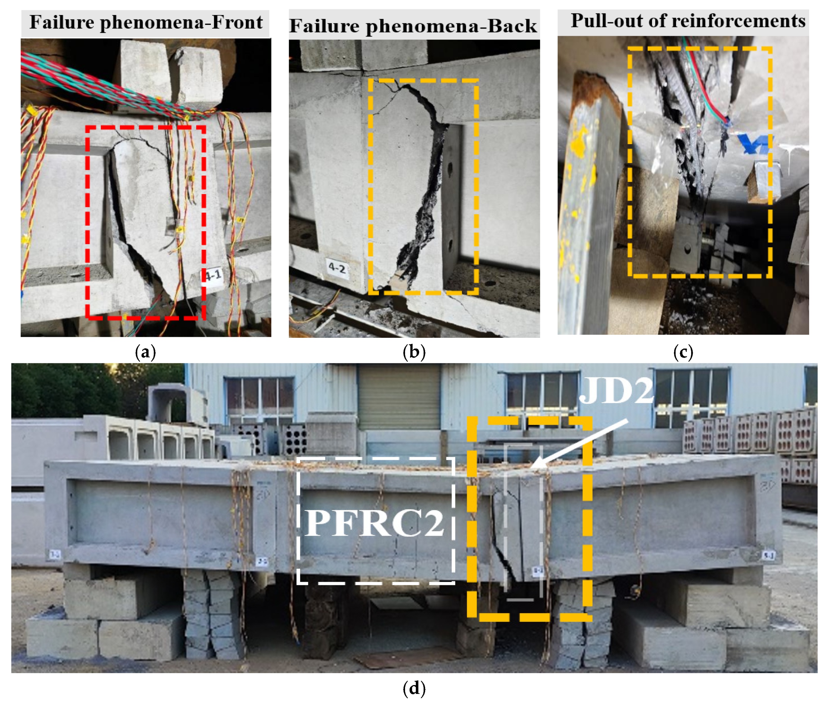
Upon completion of loading case JZ-7 (982.0 kN), sudden failure occurred in the prefabricated units. Concrete cracking initiated near JD2 at the base propagated to both side surfaces, while reinforcement bars at the JD2 bottom exhibited pull-out failure. However, no pull-out failure was observed in the I-shaped inserted steel plates, as documented in Figure 12a–d.
Theoretically, if such joints demonstrate reliable performance, as the load increases, the tensile stress on the bottom surface of the mid-span prefabricated units will gradually rise, thereby inducing the gradual initiation of cracks. The width of these cracks will continue to propagate until the tensile reinforcement at the bottom yields. Subsequently, wide cracks will appear in the middle part of the specimen, accompanied by concrete spalling; these cracks will gradually extend upward, causing flexural failure of the prefabricated units at the mid-span and eventually leading to structural failure. However, the failures observed in actual tests were concentrated on the prefabricated units adjacent to the joints. This may be attributed to the presence of blind zones in the reinforcement arrangement at the edge areas of the prefabricated units, which resulted in insufficient local load-bearing capacity of the specimen and subsequent flexural failure. The test failure modes indicate that the joints exhibit reliable connection performance and load-bearing capacity, and the primary cause of severe flexural failure near the grouted plug-in joints of prefabricated units is the weakness in local areas.

5. Finite Element Analysis and Comparative Study

5.1. Finite Element Modeling

This study employed ABAQUS-2020 software to establish the finite element model of the flexural specimen. The reinforcements were simulated using T3D2 linear truss elements while all other parts employed eight-node reduced-integration elements C3D8R. Figure 13 shows the finite element model of the inserted steel plates and concrete part of the prefabricated unit of the raft foundation.
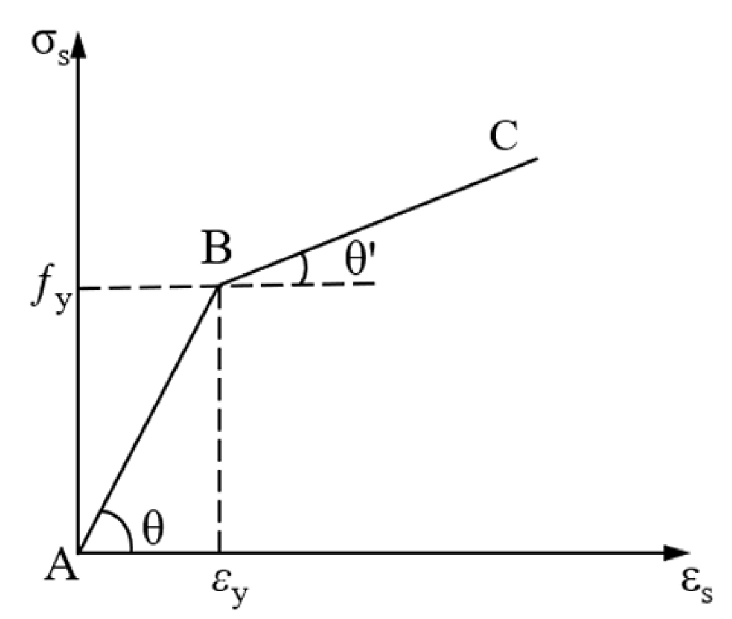
Mechanical property models for all materials were established based on experimental results. The concrete material utilized the plastic damage model (CDP model; refer to Table 7 for the relevant parameters [32]), which was built upon the model proposed by Lubliner et al. [33] and Lee et al. [34], while bilinear stress–strain relationships (as shown in Figure 14: tan θ = E   , E is the elastic modulus; t a n   θ = E t ,   E t is the tangent modulus; f y represents the yield strength; ε y represents the yield strain) were adopted for both reinforcement bars and I-shaped inserted steel plates to accurately capture their yielding and failure behavior. The elastic modulus of the steel in the hardening stage set as E t = 0.01 E and Poisson’s ratio was taken as 0.3. The calculation of the uniaxial tensile stress–strain curve of the high-strength grout is shown in Equations (1)–(3) [35].
σ t = z f t k β t ( z 1 ) 1.7 + z
z = ε ε t k
β t = 0.312 f t k 2
where z > 1 , σ t , and ε denote the uniaxial tensile stress and strain of the grout, respectively; f t k represents the characteristic value of the uniaxial tensile strength of the grout; and ε t k is the peak tensile strain of the grout corresponding to the characteristic value of the uniaxial tensile strength.
The calculation of the uniaxial compressive stress–strain curve of the grout is shown in Equations (4)–(7).
σ c = β a w + ( 3 2 β a ) w 2 + ( β a 2 ) w 3 w 1 w f c k β b ( w 1 ) 2 + w w > 1
w = ε ε c k
β a = 2.4 0.0125 f c k 2
β b = 0.157 f c k 0.785 0.905
where σ c and ε denote the uniaxial compressive stress and strain of the grout, respectively; f c k denotes the characteristic value of the uniaxial compressive strength of the grout; and ε c k is the peak compressive strain of the grout corresponding to the characteristic value of the uniaxial compressive strength.
In the finite element model, reinforcements were embedded within the concrete, while the I-shaped inserted steel plates were also embedded within the grout using the “Embedded” option in ABAQUS-2020.
The contact behavior between normal concrete and grout exerts a significant influence on simulation accuracy. Given that no visible damage was observed at the interface between grout and pre-cast element concrete during the final failure stage of the test, a simplified approach was adopted: the two materials were modeled as an integrated entity using “Tie” constraints. While this may involve a certain degree of error, it still satisfies the requirements for accuracy requirement in engineering practice. Contact interactions between adjacent prefabricated units were defined in both tangential and normal directions. The tangential behavior adopted a penalty function allowing finite sliding with a friction coefficient of 0.1, while normal behavior utilized hard contact to transmit compressive stress.
To enhance simulation accuracy, two distribution beams used in the testing were considered in the modeling. Surface-to-surface contact was assigned between the distribution beams and the concrete surface of the prefabricated units. The flexural specimen was constrained with a fixed hinge support at one end and a sliding roller support at the opposite end, as shown in Figure 15. Finally, loading was applied to the two distribution beams shown in Figure 15.
In meshing, the reinforcement grid size was set to be 10 mm. Normal concrete, high-strength grout, and I-shaped inserted steel plates were modeled using C3D8R elements with mesh sizes of 10 mm, 5 mm, and 5 mm, respectively.
Finite element analysis of the flexural specimen employed a “Static, General procedure” incorporating geometric nonlinearity. The initial time increment was set to be 0.001, with minimum and maximum increments constrained to be 1 ×10⁻⁶ and 0.1, respectively, to ensure computational stability and accuracy.

5.2. Finite Element Analysis Results

5.2.1. Comparison of Failure Phenomena

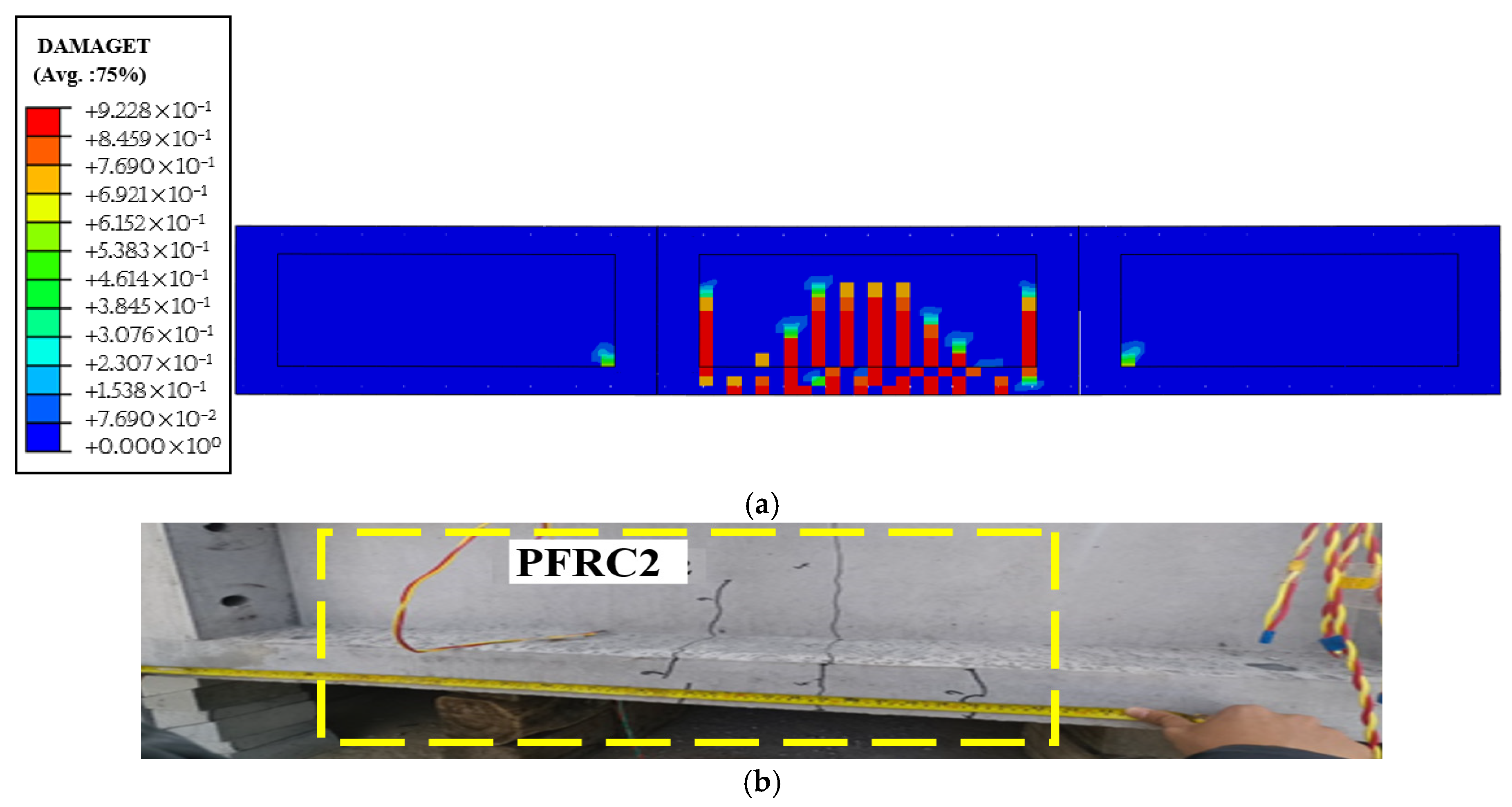
As previously described, the failure characteristics of the flexural test specimen primarily dominated as flexural failure between adjacent prefabricated units. Cracks propagated upward to the top surface and gradually penetrated to form through cracks (Figure 12d). Figure 16a displays the DAMAGET (tensile damage) contour extracted from finite element analysis at failure, indicating concentrated damage on the front face of the central prefabricated unit PFRC-2. The vertical damage zones laterally flanking the joint correspond to flexural failure regions, which is consistent with experimental observations in Figure 12a,b. The central damage zone represents vertical cracking from excessive bending tension, as shown in Figure 16b.
According to the finite element results, bottom damage predominantly localized on PFRC-2 (Figure 17a), comprising three distinct zones. Two linear damage areas were near the interface, which is aligned with the flexural-induced crack extensions in Figure 11c, while the third zone reflects tensile cracks from mid-span bending overload, matching measured cracks in Figure 17b.
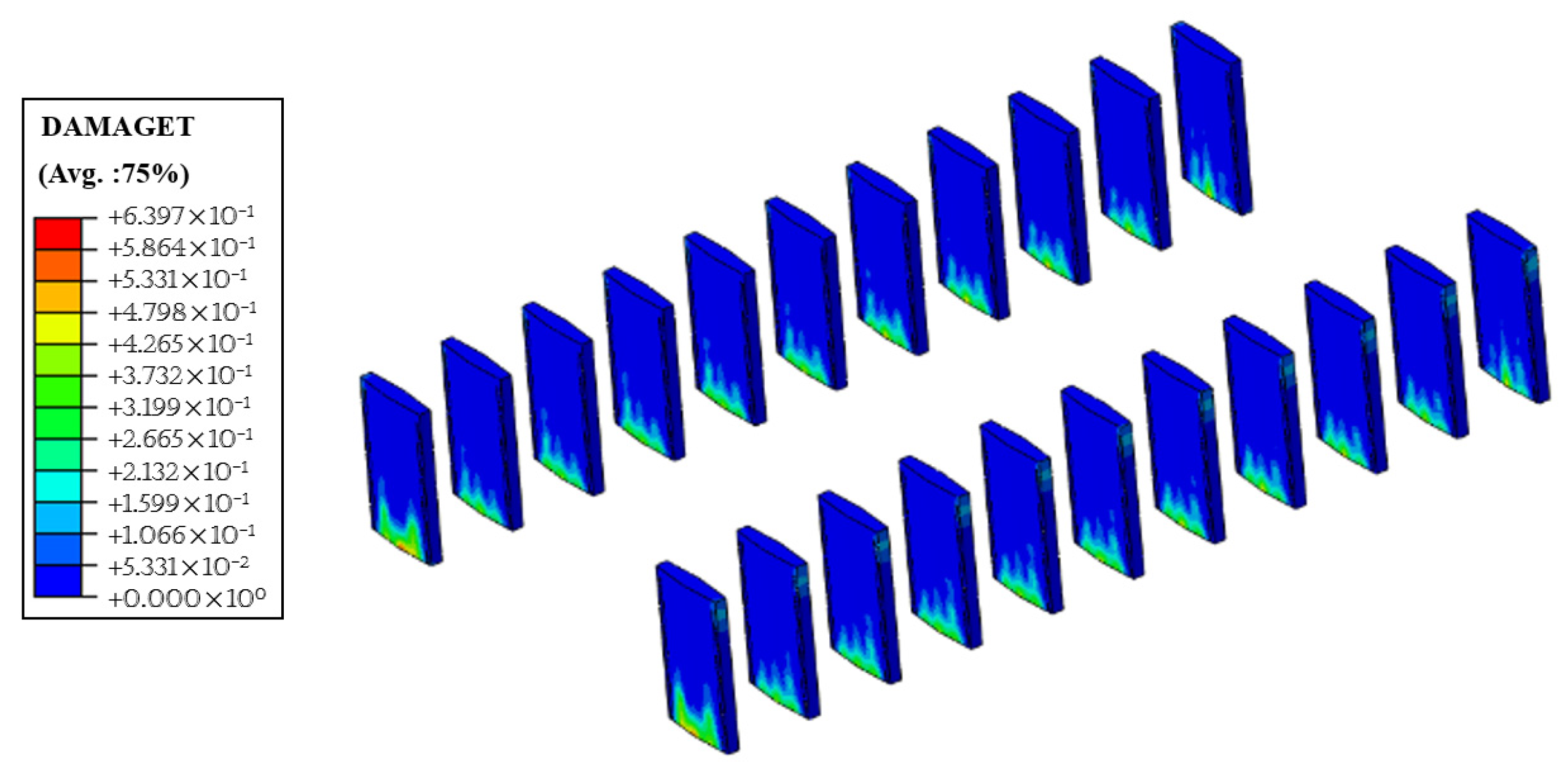
Figure 18 presents the tensile damage (DAMAGET) contour of the high-strength grout obtained from the finite element analysis. The maximum tensile stress reached only 64% of its ultimate tensile strength and it validates that no cracking occurred in the grout, which is consistent with experimental observations. Additionally, elevated damage factors localized at the base of the grout primarily resulted from a high bending moment inducing tension in the underlying part.
Figure 19a,b display the Mises stress contours of the reinforcement bars and inserted steel plates, revealing that neither component yielded. The maximum Mises stress in the reinforcement bars reached 187.5 MPa at the bottom layer of the prefabricated unit PFRC-2, while the peak stress in the inserted steel plates was 164.7 MPa at the bottom of the plate. It can be seen from the typical position strain curves of I-shaped inserted steel plates obtained from the test (as shown in Figure 20) that the steel plates did not exhibit yielding behavior. The maximum strain was approximately 700 μ ε , which occurred at the bottom of Type A inserted plates at location JD-1. The minimum strain was around −250 μ ε . This indicates that at this stage, the steel plates sustained a maximum tensile stress of approximately 140 MPa and a maximum compressive stress of about 50 MPa. Comparison between the two stress values reveals that the maximum stress of the inserted plates obtained from the test accounted for 85% of that obtained from the finite element analysis, and the two results agree reasonably well.

5.2.2. Load–Displacement Behavior

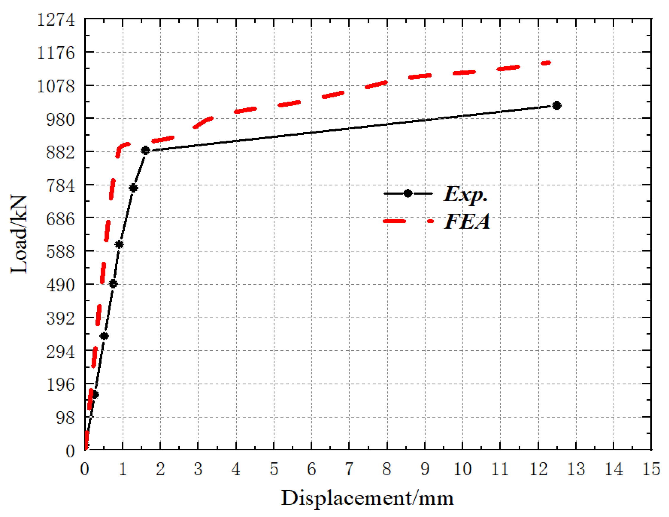
Figure 21 presents the load versus mid-span displacement curves obtained from both full-scale flexural testing and finite element analysis. Among them, the data of the experimental load–displacement curves refer to the total load and corresponding displacement gauge readings after each load level is applied.
The specimen’s load–displacement curve exhibited two distinct phases, i.e., elastic and plastic stages. During the elastic phase, the slopes from the experimental and finite element curves are 549.8 kN/mm and 945.7 kN/mm, respectively, yielding a ratio of 0.58. This indicates a higher bending stiffness in the numerical model, primarily attributed to imperfect contact between the prefabricated units during testing. Additional factors might include concrete floor settlement, amplifying measured displacements and reducing experimental stiffness.
The peak load in the plastic phase is taken as the ultimate bearing capacity. The maximum load applied during the test was 982.0 kN. The ultimate load obtained from the finite element analysis was 1145.6 kN, which means the maximum bending moment obtained from the experimental test is 736.5 kN·m, while the value obtained from the FEA was 859.5 kN·m. Based solely on cross-sectional dimensions (Figure 3), reinforcement layout, and material properties in Table 2 and Table 3 (excluding upper-layer reinforcement), the theoretical cross-section bending capacity of an individual prefabricated unit is 892.8 kN·m. Experimental and numerical ultimate bending moments reached 0.83 and 0.96 of the theoretical value, demonstrating that the proposed grouted plug-in connection enables prefabricated raft foundations to achieve sufficient flexural bearing capacity.

6. Conclusions

This paper proposes a modular prefabricated raft foundation comprising prefabricated units interconnected via inserted steel plates and high-strength grout. For HGIS electrical equipment raft foundations, a flexural test specimen consisting of three prefabricated units was designed. Full-scale flexural testing under two line-loadings and finite element analysis yield the following conclusions:
(1)
Upon reaching the ultimate load, there was no obvious damage at the inserted plate joints, while pronounced flexural failure occurred near the inserted plate joints of the specimen. Therefore, the connection joints possess sufficient strength, and the configuration of the steel reinforcement cages in the prefabricated units needs to be optimized to improve their flexural resistance.
(2)
In the elastic phase, the slopes of the experimental and numerical load–displacement curves are 549.8 kN/mm and 945.7 kN/mm, respectively, indicating that the numerical model has greater bending stiffness. Material parameters or contact settings in the finite element modeling have increased the model stiffness to a certain extent, thereby enhancing its bending stiffness. The ultimate bending moments obtained from the test and simulation are 736.5 kN·m and 859.5 kN·m (ratio: 0.86, discrepancy: 14%), respectively, reflecting the difference between the two. All data demonstrate that the prefabricated raft foundation specimens possess qualified bending stiffness and exhibit good load-bearing capacity.
(3)
Excluding upper-layer reinforcement, the theoretical cross-section flexural bearing capacity of a single prefabricated unit is 892.8 kN·m. The experimental ultimate moment reaches 0.83 times this value, demonstrating that grouted plug-in connections enable prefabricated raft foundations to achieve good load-bearing performance, with favorable overall performance that can meet the load requirements of HGIS equipment.
Overall, the full-scale test of the prefabricated raft foundation in this study still has limitations and shortcomings. For example, the size of the assembled raft foundation is fixed; therefore, the conclusions of this study are mainly applicable to specimens composed of three prefabricated units and may not be applicable to other larger size similar specimens. More research works are expected in future.

Author Contributions

Conceptualization, H.J., X.W., K.Z. and W.J.; methodology, X.W., T.L., H.J., X.H. and Y.T.; investigation, X.W., X.H., S.H. and X.T.; writing—original draft preparation, X.W., S.H., T.L. and X.T.; writing—review and editing, T.L. and S.H.; visualization, X.H., S.H., and X.W.; project administration, H.J., X.W., K.Z., Y.T. and W.J. All authors have read and agreed to the published version of the manuscript.

Funding

This research was funded by Funding Project: Science and Technology Project of PowerChina Hubei Electric Engineering Co., Ltd. (03-Q-B-2023-002).

Data Availability Statement

Data are contained within the article.

Acknowledgments

The authors thank all the people who have supported this research.

Conflicts of Interest

Author Hongtao Ju, Kai Zhang, and Wen Jiang were employed by the company Power China Hubei Electric Engineering Co., Ltd. Author Yu Tang was employed by the company State Grid Hubei Zhongchao Construction Management Company. The remaining authors declare that the research was conducted in the absence of any commercial or financial relationships that could be construed as a potential conflict of interest.

References

  1. Shao, G.; Liu, J.; Zou, J.; Zhao, G.; Zheng, T.; Meng, X.; Tian, L.; Liu, J. Experimental Study on the Bearing Performance of Segmented Prestressed Assembled Foundation with Full-Scale Testing. ACT 2025, 23, 123–137. [Google Scholar] [CrossRef]
  2. Zhang, W.; Ding, Z.; Kang, H.; Lin, P.; Wen, G.; Yong, D.; Lu, C.; Wang, J.; Meng, X.; Rong, K.; et al. Research on Bearing Capacity of a Novel Prestressed Concrete Prefabricated Foundation with High Uplift Resistance Characteristic. Buildings 2024, 14, 3743. [Google Scholar] [CrossRef]
  3. Wang, W.; Gao, Y.; Wang, Z.; Zhang, L.; An, Z.; Shao, S. An Experimental Study on Plate Splicing of Prefabricated Plate Foundation. Buildings 2023, 13, 2114. [Google Scholar] [CrossRef]
  4. Wang, W.; Ma, H.; Shao, S.; Wang, Z.; Gao, Y.; Zheng, X.; Zhang, Z. An Experimental Study on Plate Splicing of a New Prefabricated Plate-Type Foundation. KSCE J. Civ. Eng. 2025, in press. [Google Scholar] [CrossRef]
  5. Li, X.; Hao, H.; Wang, H.; Zhang, L.; Guo, Y.; Lian, J.; Du, Y.; Wang, X.; Zeng, C. Design and Analysis of a New Prefabricated Foundation for Onshore Wind Turbines. Buildings 2024, 14, 193. [Google Scholar] [CrossRef]
  6. Wang, H.; Liu, C.; Guo, Y.; Hao, H.; Zhang, L. Experimental Study on the Mechanical Characteristics of Prefabricated Dense Ribs Foundation for Onshore Wind Turbines. Structures 2025, 73, 108273. [Google Scholar] [CrossRef]
  7. Zhou, Z.; Zhou, X.; Wang, Y.; Ke, K. Axial Compression Behavior of Steel-UHPC Grouted Connections for Offshore Wind Turbines. J. Constr. Steel Res. 2025, 235, 109831. [Google Scholar] [CrossRef]
  8. Li, L.; Yan, N.; Liu, Z.; Wu, W.; Jiang, G.; Chen, L.; Liu, H. Investigation on the Cyclic Laterally-Loaded Response of Pile-Bucket Foundation with Grouted Connection. Mar. Struct. 2025, 103, 103808. [Google Scholar] [CrossRef]
  9. Tian, W.; Li, Z.; Wan, H. Design and Analysis of a Novel Prefabricated Foundation for Substation Buildings. Buildings 2024, 14, 4073. [Google Scholar] [CrossRef]
  10. Pul, S.; Senturk, M.; Ilki, A.; Hajirasouliha, I. Experimental and Numerical Investigation of a Proposed Monolithic-like Precast Concrete Column-Foundation Connection. Eng. Struct. 2021, 246, 113090. [Google Scholar] [CrossRef]
  11. Zhou, X.; Ding, R.; Guo, B.; Nie, X.; Fan, J. Connections between Precast Hollow Concrete Columns and Foundations Using UHPC and Rebar Lap Splices. Eng. Struct. 2024, 321, 118982. [Google Scholar] [CrossRef]
  12. Fan, J.-J.; Feng, D.-C.; Wu, G.; Hou, S.; Lu, Y. Experimental Study of Prefabricated RC Column-Foundation Assemblies with Two Different Connection Methods and Using Large-Diameter Reinforcing Bars. Eng. Struct. 2020, 205, 110075. [Google Scholar] [CrossRef]
  13. Liu, B.; Zhang, L.; Sun, H.; Feng, M.; Dou, K. Side Shear Strength and Load-Transfer Mechanism of Corrugated Steel Column–Foundation Socket Connection. Case Stud. Constr. Mater. 2022, 17, e01377. [Google Scholar] [CrossRef]
  14. Cao, J.; Wang, X.; Yang, L.; Chen, C. Finite Element Analysis and Failure Modes of CFST Pier-to-Foundation Connection with Tubed RC Encasement. Structures 2025, 80, 109994. [Google Scholar] [CrossRef]
  15. Cogurcu, M.T.; Uzun, M. Experimental Investigation of a New Precast Column-Foundation Connection under Cyclic Loading. J. Build. Eng. 2022, 50, 104245. [Google Scholar] [CrossRef]
  16. Qi, J.; Ye, Y.; Jiang, L.; Lü, W.; Lu, B.; Wu, J. A Study on the Mechanical Behavior of a Wind Turbine Foundation with a Constrained Structural Shear Connector. Buildings 2024, 14, 3162. [Google Scholar] [CrossRef]
  17. Chen, L.; Wang, Z.; Liu, H. Shear Performance of Assembled Bamboo–Concrete Composite Structures Featuring Perforated Steel Plate Connectors. Buildings 2025, 15, 1376. [Google Scholar] [CrossRef]
  18. Di, J.; Liao, X.; Huang, X.; Wu, M.; Zhao, Y.; Guo, N. Experimental Study and Numerical Simulation of the Mechanical Behaviour of a Bamboo Scrimber Beam–Column Connected to a Concrete Joint Embedded with Steel-Reinforcing Bars. Structures 2025, 81, 110321. [Google Scholar] [CrossRef]
  19. Xiong, X.; Wei, Z.; Zhang, D.; Liu, J.; Xie, Y.; He, L. An Experimental Study on the Seismic Performance of New Precast Prestressed Concrete Exterior Joints Based on UHPC Connection. Buildings 2025, 15, 729. [Google Scholar] [CrossRef]
  20. Zhang, G.; Yang, C.; Zhu, Z.; Xu, L.; Han, Q.; Zhou, L.; Xu, S.; Du, X. Investigation on Socket Depth of Prefabricated Assembly CFST Column-Beam Joints by Cyclic Load Test. J. Build. Eng. 2025, 112, 113884. [Google Scholar] [CrossRef]
  21. Xu, Y.; Chen, Z.; Miao, X.; Chen, Z. Research on Grouting Connection Technology in PHC Pipe Piles and Bearing Platform Integration. J. Build. Eng. 2025, 106, 112633. [Google Scholar] [CrossRef]
  22. Bai, J.; Yang, J.; Liang, T.; Jin, S. Seismic Performance of Novel Modular Steel Structural Joint with Shear Key Double-Layer Grouting Connection. J. Constr. Steel Res. 2025, 232, 109640. [Google Scholar] [CrossRef]
  23. Zhu, G.; Zhou, M.; Song, J.; Tian, X. Seismic Performance of the Precast Segmental Hollow Section Bridge Columns with UHPC Wet Joint Connections and UHPC Grouted Duct Connections. Structures 2025, 71, 108009. [Google Scholar] [CrossRef]
  24. Yan, Q.; Chen, T.; Xie, Z. Seismic Experimental Study on a Precast Concrete Beam-Column Connection with Grout Sleeves. Eng. Struct. 2018, 155, 330–344. [Google Scholar] [CrossRef]
  25. Qu, X.; Yang, J.; Yan, J. Study on the Eccentric Load-Bearing Performance of Prefabricated Concrete-Filled Steel Tube Columns with “Inner Tube-Flange-Grouting” Connections. Structures 2025, 80, 110043. [Google Scholar] [CrossRef]
  26. Li, M.; Meng, F.; Zhang, L.; Wu, Q. Experimental and Numerical Study on Flexural Behavior of Prefabricated Bottom Slabs with Rabbeted Grouting Splicing Joints. Structures 2024, 70, 107755. [Google Scholar] [CrossRef]
  27. Wu, X.; Lu, L.; Jin, J.; Liu, C.; Ding, Z.; Ji, P. Study on Seismic Response of a Novel Prefabricated Box Culvert with Split Components Based on Shaking Table Test. J. Build. Eng. 2024, 84, 108548. [Google Scholar] [CrossRef]
  28. Zhao, P.; Chen, C.; Shao, X.; Rong, X. Shear Stress at Joint of Prefabricated-Composite Box Girders with Corrugated Steel Webs. J. Constr. Steel Res. 2024, 212, 108307. [Google Scholar] [CrossRef]
  29. GB/T 228.1-2010; Metallic Materials-Tensile Testing-Part 1: Method of Test at Ambient Temperature. China Architecture & Building Press: Beijing, China, 2010.
  30. GB/T 50081-2019; Standard for Test Methods of Mechanical Properties of Ordinary Concrete. China Architecture & Building Press: Beijing, China, 2019.
  31. GB/T 17671-2021; Test Method of Cement Mortar Strength (ISO Method). China Standards Press: Beijing, China, 2021.
  32. Saiidi, M. Hysteresis Models for Reinforced Concrete. ASCE J. Struct. Div. 1982, 108, 1077–1087. [Google Scholar] [CrossRef]
  33. Lubliner, J.; Oliver, J.; Oller, S.; Onate, E. A Plastic-damage model for concrete. Int. J. Solids Struct. 1989, 25, 299–326. [Google Scholar] [CrossRef]
  34. Lee, J.; Fenves, G.L. Plastic-damage model for cyclic loading of concrete structure. J. Eng. Mech. 1998, 124, 892–900. [Google Scholar] [CrossRef]
  35. Zhang, J. Research on Mechanical Performance of New Prefabricated Plate Assembly Joint. Master’s Thesis, Jiangsu University, Zhenjiang, China, April 2023. [Google Scholar]
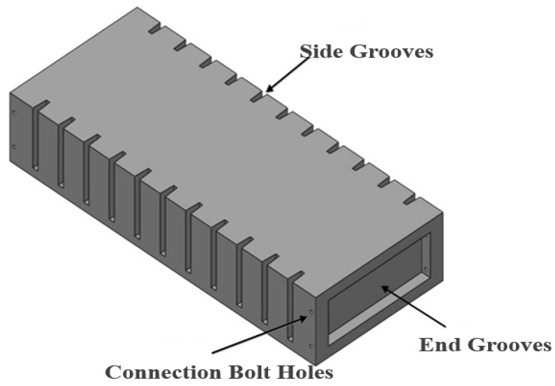
Figure 1. Prefabricated unit for raft foundation.
Buildings 15 03931 g001
Figure 2. Grouting connection.
Buildings 15 03931 g002
Figure 3. Reinforcement layout of prefabricated unit for raft foundation. (a) Upper-layer reinforcements. (b) Lower-layer reinforcements. (c) Reinforcement details at side grooves.
Buildings 15 03931 g003
Figure 4. Dimensions of the groove.
Buildings 15 03931 g004
Figure 5. Dimensions of inserted I-shaped steel plate.
Buildings 15 03931 g005
Figure 6. Flexural testing specimen. (a) Schematic diagram of the specimen. (b) Set-up of testing specimen.
Buildings 15 03931 g006
Figure 7. Loading schematic diagram.
Buildings 15 03931 g007
Figure 8. Arrangement and numbering of the displacement gauges.
Buildings 15 03931 g008
Figure 9. Rear view of displacement gauges.
Buildings 15 03931 g009
Figure 10. Strain gauge arrangement of the inserted steel plate. (a) The I-shaped inserted steel plates at key positions. (b) A-type strain gauge arrangement. (c) B-type strain gauge arrangement. (d) C-type strain gauge arrangement.
Buildings 15 03931 g010
Figure 11. Cracks observed in loading case JZ-5. (a) Front-side crack. (b) Back-side crack. (c)Bottom crack.
Buildings 15 03931 g011
Figure 12. Specimen failure phenomena. (a) Front viewpoint. (b) Back viewpoint. (c) Pull-out of reinforcements at the bottom of the specimen. (d) Global failure of the specimen (Front viewpoint).
Buildings 15 03931 g012
Figure 13. Finite element models of inserted steel plates and concrete part of the prefabricated unit of the raft foundation. (a) Inserted steel plate. (b) Concrete part of the prefabricated unit of raft foundation.
Buildings 15 03931 g013
Figure 14. Bilinear stress–strain relationship of the steel plates and rebars.
Buildings 15 03931 g014
Figure 15. Loading and constraints applied.
Buildings 15 03931 g015
Figure 16. Damage analysis and experimental observations on unit PFRC-2 front face. (a) Finite element damage contour (DAMAGET). (b) Experimental crack distribution.
Buildings 15 03931 g016
Figure 17. PFRC-2 unit bottom damage. (a) Finite element damage contour (DAMAGET). (b) Experimental crack distribution.
Buildings 15 03931 g017
Figure 18. Grout damage distribution.
Buildings 15 03931 g018
Figure 19. Steel stress distributions. (a) Steel bars. (b) Insert steel plates.
Buildings 15 03931 g019aBuildings 15 03931 g019b
Figure 20. Load–strain curve of inserted steel plates.
Buildings 15 03931 g020
Figure 21. Comparison of the load versus mid-span displacement curves between experimental test and FEA.
Buildings 15 03931 g021
Table 1. Loading cases and magnitudes.
Case No.Number of Loading BlocksLoad Per Case
(kN)
Cumulative Load (kN)
JZ-15163.7163.7
JZ-26171.5335.2
JZ-34119.6454.7
JZ-45147.0601.7
JZ-55147.0748.7
JZ-65147.0896.7
JZ-7385.3982.0
Table 2. Mechanical properties of the steel reinforcement.
Specimen IDYield Strength (MPa)Ultimate Strength (MPa)Elastic Modulus (MPa)Elongation After
Fracture
(%)
1445580206,43316.9
2460595226,68214.5
3430600214,56912.7
Avg. 445592215,89514.7
Table 3. Mechanical properties of normal C40 concrete.
Specimen TypeSpecimen IDCross-Section Dimensions (mm)Failure Load (kN)Compressive Strength (MPa)
Cube
compressive
strength 1
1150.30 × 150.50 × 150.001066.847.2
2150.60 × 149.30 × 150.001103.449.1
3150.10 × 150.80 × 150.001088.148.1
Avg.-1086.148.1
Cylinder
compressive
strength 2
1150.30 × 149.50 × 300.00886.539.5
2149.60 × 150.40 × 300.00900.640.0
3149.50 × 150.70 × 300.00915.140.6
Avg.-900.740.0
1,2 The cube compressive strength was determined using standard specimens of dimensions 150 × 150 × 150 mm, while the cylindrical compressive strength was measured using specimens of dimensions 150 × 150 × 300 mm, as mandated by the specification [29,30].
Table 4. Elastic modulus of normal C40 concrete.
Specimen IDCross-Section Dimensions
(mm)
Compressive Strength
(MPa)
Ec
(MPa)
1151.30 × 150.50 × 300.0039.635,898
2149.70 × 150.80 × 300.0039.434,903
3150.50 × 150.90 × 300.0040.332,892
Avg.-39.834,564
Table 5. Mechanical properties of the inserted steel plates.
Specimen IDYield Strength (MPa)Ultimate Strength (MPa)Elastic Modulus (MPa)Elongation
(%)
1325465203,35512.9
2315465203,34114.8
3305445203,35913.3
Avg.315458.3203,351.713.7
Table 6. Mechanical properties of the high-strength grout.
Specimen IDCross-Section Dimensions (mm)Flexural Failure Load (kN)Flexural Strength 1 (MPa)Compressive Failure Load (kN)Compressive Strength (MPa)
139.80 × 40.10 × 160.003.99.0132.982.3
239.90 × 40.00 × 160.003.89.1127.880.5
340.00 × 40.10 × 160.003.99.0130.579.8
Avg.--9.0-80.9
1 For cement-based grouting materials, the flexural strength test is mainly conducted in accordance with GB/T 17671-2021 “Test method for strength of cement mortar (ISO method)” [31]. This standard specifies that prismatic molds with dimensions of 40 × 40 × 160 mm shall be used, and the specimens shall be cured for 28 days in a standard curing room with a temperature of 20 ± 2 °C and a relative humidity of >95% before the flexural strength test is performed.
Table 7. Parameters of the CDP model.
ψ 1  2 f b 0 / f c 0  3 K c  4 μ  5
380.11.160.66670.005
1 ψ/° is dilation angle; 2  is flow potential eccentricity; 3  f b 0 / f c 0 is the ratio of the initial biaxial compressive strength to the uniaxial compressive strength; 4  K c reprents the yield eccentricity; 5  μ represents the viscosity parameter.
Disclaimer/Publisher’s Note: The statements, opinions and data contained in all publications are solely those of the individual author(s) and contributor(s) and not of MDPI and/or the editor(s). MDPI and/or the editor(s) disclaim responsibility for any injury to people or property resulting from any ideas, methods, instructions or products referred to in the content.