Abstract
With the continuous advancement of urban construction, inertial sensors are increasingly used in the detection of underground pipelines. However, inertial measurement units (IMUs) are susceptible to a variety of error sources, leading to the accumulation of position estimation errors over time, which severely restricts their positioning accuracy. This paper provides a systematic review of IMU calibration and drift suppression error compensation methods applicable to underground pipeline environments. Building upon this foundation, it innovatively proposes a three-tiered review framework based on “error characteristics–compensation mechanisms–application scenarios”. The framework begins with the characterization of error factors, maps them to corresponding compensation mechanisms, and then applies them to specific operating conditions. It identifies current research limitations in real-time performance, robustness, experimental validation, and standardized evaluation. Future efforts should focus on designing lightweight fusion algorithms, integrating deep learning with sensor fusion, and establishing standardized testing platforms. This paper aims to summarize the current state and development trends of inertial sensor error compensation methods, providing a reference for advancing related technologies while offering beginners a clear and systematic learning path.
1. Introduction
With the growth of energy demand and the accelerated construction of urban infrastructure, long-distance underground pipelines are widely used in the fields of water supply, electricity, communications, and industry [1]. With the continuous expansion in the density and scale of underground pipeline networks, increasingly stringent requirements have been placed on the detection and positioning accuracy of their spatial distribution [2]. However, the closed nature of the underground environment and severe signal attenuation significantly limit the applicability of traditional positioning techniques such as total stations and the Global Navigation Satellite System (GNSS). In this context, IMU-based pipeline detection has emerged as a promising alternative solution [3,4]. The IMU is particularly well-suited for pipeline inspection in underground, enclosed, and complex environments, owing to its capability for autonomous operation without dependence on external signals. By integrating angular velocity, the IMU derives attitude information, while double integration of acceleration enables displacement estimation [5,6]. However, errors such as zero bias, random walk, and scale factor of IMUs accumulate over time, which seriously limits the accuracy of long-time inertial positioning [7]. In addition, external interference factors such as ambient temperature changes and the complexity of the internal structure of the pipeline further exacerbate the error dispersion [8,9,10,11], resulting in positional deviations of several meters or even tens of meters often occurring in long-distance pipeline detection, making it difficult to satisfy the demand for high-precision positioning in practical engineering. Therefore, how to effectively suppress and compensate the drift error in inertial positioning becomes the core challenge to achieving high-precision trajectory estimation.
In recent years, for the problem of error suppression in pipeline inertial positioning environments, researchers have proposed a variety of error modeling and compensation methods. The traditional methods are mainly implemented through sensor calibration and initial error modeling, such as laboratory calibration, temperature compensation, and higher-order function fitting, which can effectively calibrate the normal value error under static conditions [12,13,14]. For the correction of dynamic errors, state estimation algorithms such as the Kalman Filter (KF), Extended Kalman Filter (EKF), and Unscented Kalman Filter (UKF) are widely employed to integrate system models with observational data for optimal estimation. These methods are supported by a solid theoretical foundation and exhibit strong adaptability to various systems; however, their performance is highly sensitive to inaccuracies in modeling the statistical characteristics of noise [15,16,17,18,19]. Meanwhile, some researchers have explored the use of path constraints or pipeline geometric features for error compensation. These approaches demonstrate good performance in structured environments; however, their applicability relies heavily on prior environmental knowledge, which limits their generalizability [20,21,22]. With the advancement of multi-sensor fusion techniques, the integration of magnetometers, odometers, vision sensors, and other auxiliary devices with IMUs has been shown to significantly enhance system robustness. However, this improvement comes at the expense of increased system complexity and cost, which restricts their applicability in narrow, dark, or dust-laden pipeline environments [23,24,25]. In recent years, deep learning approaches have been increasingly employed to model and compensate for IMU errors in an end-to-end manner, utilizing architectures such as Long Short-Term Memory (LSTM) networks and convolutional neural networks (CNNs). These methods demonstrate strong capabilities in nonlinear fitting and environmental adaptability; however, they suffer from limited interpretability and a heavy reliance on large-scale, high-quality training data [26]. Overall, while existing methods exhibit distinct advantages across different application scenarios, they also share inherent limitations. Future research should focus on addressing system-level constraints such as energy consumption, quality, and cost while ensuring accuracy and robustness, thereby achieving lightweight and efficient drift error compensation tailored for narrow pipeline environments.
The aim of this paper is to provide a systematic review of recent research progress on drift error calibration and compensation in inertial positioning systems for underground pipelines. Specifically, it summarizes the core concepts and application scenarios of various approaches, elucidates their underlying mechanisms and interrelationships, and identifies key challenges, as well as future research directions. It is worth noting that the drift errors of low-cost IMUs are highly complex, being influenced by multiple coupled physical factors. Consequently, related research inherently spans several disciplines, including inertial navigation theory, sensor physics, and error modeling and estimation methods. In recent years, the number of review studies on inertial positioning and integrated navigation has gradually increased, both domestically and internationally. Most of these works have concentrated on topics such as visual–inertial navigation initialization [27], temperature error compensation of MEMS gyroscopes [28], and learning-based methods for pedestrian inertial positioning [29]. While these studies have effectively summarized research progress in their respective domains, notable gaps remain in the context of underground pipeline environments. Specifically, existing reviews lack a systematic discussion of special working conditions, such as strong magnetic interference, metallic structures, and extended operation without external aiding information. Moreover, the closed-loop connection among error characteristics–compensation mechanisms–application scenarios has not been sufficiently established, and the analysis of dynamic drift phenomena remains superficial. In addition, much of the prior work emphasizes engineering implementation, empirical formulas, or filtering methods. Although reviews of learning-driven approaches have touched upon deep learning and self-supervised techniques, they have seldom addressed weakly supervised signal construction or low-power deployment. Meanwhile, Table 1 summarizes the thematic scope and primary limitations of relevant review studies in recent years to highlight the innovative contributions of this paper. Based on this, this paper, on the basis of a comprehensive overview of various compensation methods, pays more attention to the clear presentation of the basic concepts and the logical chain of progression, and it strives to reduce the threshold of understanding, providing researchers, especially beginners, with a clear structure, a clear theoretical framework, and an overall cognitive perspective.

Table 1.
Comparison of research focuses among existing IMU calibration and compensation reviews.
This paper will review the drift errors and compensation methods in pipeline inertial positioning systems. Section 2 summarizes the systematic literature search strategy; the sources of drift error are summarized in Section 3; the accuracy improvement methods for IMU calibration are summarized in Section 4; the accuracy improvement methods for error compensation are summarized in Section 5; and the current research deficiencies and challenges are discussed and summarized, and the possible future development and research directions are looked forward to. Finally, the shortcomings and challenges of the current research are discussed and summarized, and the possible future development trends and research directions are anticipated. The overall structure of this paper is shown in Figure 1.
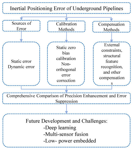
Figure 1.
Overall structure diagram.
2. Methods
2.1. Search Strategy
We conducted a systematic literature search across several major databases, including Web of Science, IEEE Xplore, and Google Scholar, to identify studies related to error sources, calibration methods, and compensation techniques of inertial positioning in underground pipeline applications. The search scope covers the literature from 2015 to 2025 and, of course, includes a small number of significant papers published prior to 2015. Keywords included combinations of “inertial measurement unit (IMU)”, “error calibration”, “drift compensation”, “underground pipeline”, and “sensor fusion”. In addition, the reference lists of included studies were screened to identify further relevant research.
2.2. Eligibility Criteria
The inclusion criteria were as follows:
- (1)
- Sensor category: Studies conducted in underground pipeline environments that employ MEMS IMUs, fiber-optic gyroscopes (FOGs), or IMU-centric multi-sensor fusion.
- (2)
- Pipe diameter: Focus on small-to-medium diameters (DN 100–600 mm) for experiments and analyses.
- (3)
- Studies focusing on inertial positioning in underground pipelines or GNSS-denied environments;
- (4)
- Studies that proposed, tested, or reviewed IMU calibration and error compensation methods;
- (5)
- Studies published in peer-reviewed journals or conference proceedings.
The exclusion criteria were as follows:
- (1)
- Studies not related to underground positioning;
- (2)
- Studies lacking sufficient methodological detail;
- (3)
- Non-English publications, unless they provided unique technical contributions.
Finally, the literature was categorized by field. The 119 included studies covered calibration (n = 52); compensation and integration (n = 12); and subsurface applications, including pipelines, utility tunnels, downhole operations, and small-diameter PIGs (n = 41). Review articles, tutorials, and background literature (n = 14) were used to provide contextual information. The classification proportion chart is shown in Figure 2.
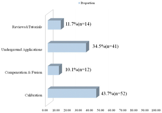
Figure 2.
The classification proportion chart.
2.3. Selection Process
The process of study identification, screening, and inclusion followed the PRISMA Extension for Scoping Reviews (PRISMA-ScR) guidelines. Two reviewers independently screened the titles and abstracts of all retrieved records, and potentially relevant studies were subsequently assessed in full text to determine eligibility. Any discrepancies were resolved through discussion until consensus was reached. The PRISMA checklist is included in the Supplementary Materials to ensure transparency in the review process.
The overall study selection process is illustrated in the PRISMA flow diagram (Figure 3), which shows the number of records identified, screened, excluded, and finally included in this review.
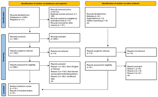
Figure 3.
PRISMA flow diagram showing the identification, screening, eligibility assessment, and inclusion of studies.
3. Sources of Drift Errors in Inertial Positioning of Underground Pipelines
The IMU is a sensor consisting of a gyroscope and an accelerometer. The gyroscope is used to measure the angular velocity, which assists in estimating the attitude change; the accelerometer is used to measure the specific force, which can further deduce the velocity and displacement information. In the inertial navigation system, the measurement accuracy of IMU directly determines the navigation performance of the whole system. However, the output of the IMU is not ideal, as it is affected by various factors, such as zero bias, scale-factor error, non-orthogonal error, and sensor noise. Therefore, it is necessary to model the measurement error to describe the relationship between the actual output of the sensor and the desired value.
For gyroscopes, according to reference [6], the measured value can be expressed as Equation (1):
where is the measured value (deg/h); is the true angular velocity (deg/h); is the gyroscopic zero bias (deg/h); is the gyroscopic scale factor-error matrix; is the gyroscope cross-axis coupling error matrix; and is the gyroscope sensor noise vector (deg/h), where the matrices , , and have the following specific form.
For accelerometers, according to reference [6], the measured value can be expressed as Equation (3):
where is the measured value (); is the specific force (); is the accelerometer zero bias (); is the linear scale-factor error matrix; is the nonlinear scale-factor error matrix; is the cross-axis coupling matrix; is the gravitational anomaly; and is the accelerometer sensor noise vector.
Modeling errors can suppress sensor drift during operation, but the performance of accelerometers, which measure acceleration, and gyroscopes, which measure angular velocity, are susceptible to a wide range of errors [35], which are classified into static and dynamic errors. Static errors are systematic deviations introduced by sensor structure, manufacturing and assembly, such as zero bias, non-orthogonal errors, and installation errors [36], which are stationary or slowly varying in character, and can usually be compensated by laboratory multi-position calibration or systematic calibration methods, while dynamic errors are time-dependent errors caused by random processes such as scaling factor errors, noise, random wandering, temperature drift, etc. [37]. Errors, which are unpredictable and can only be reduced by approximate descriptions through statistical modeling, filtering, and multi-sensor fusion, are difficult to eliminate completely [38].
3.1. Static Error
Static error refers to the systematic output error that still exists when the sensor is at rest, the static error does not change abruptly with the change in motion state and time, and mainly originates from the manufacturing process, assembly accuracy and environmental effects. It can be measured and calibrated in laboratory calibration [39]. Static error, also called additive error, is divided into zero-bias error, non-orthogonal error, and installation error, while zero-bias error includes static zero-bias error, temperature-drift zero-bias error, etc. [30]. The initial calibration of the IMU zero bias is usually calibrated to the static error, which will be amplified in the subsequent integration process if it is not adequately calibrated [40].
3.1.1. Zero-Bias Error
Zero-bias error is divided into constant zero bias, temperature-drift zero bias, zero-bias repeatability, zero-bias instability, acceleration sensitivity, etc. When the measured physical quantity is zero, the measured value output from accelerometers and gyroscopes is usually referred to as zero bias. Figure 4a shows the zero-bias-error schematic diagram.

Figure 4.
Conceptual diagram of IMU error classification: (a) zero-bias error schematic diagram; (b) non-orthogonal error schematic; (c) installation error diagram; (d) linear scale factor error diagram; (e) nonlinear scale-factor error diagram; (f) noise diagram.
Static zero bias refers to the non-zero value output by an IMU when completely stationary, manifesting as a constant offset also known as a constant zero bias. It is primarily caused by manufacturing errors, internal component stresses, and electrical imbalances [41]. Although static zero bias can be significant in magnitude, it can be calibrated during initial startup by keeping the device stationary.
Temperature drift zero bias is the amount of change in gyroscope zero bias over its rated operating temperature range relative to the room-temperature zero-bias value, and also reflects the temperature sensitivity of the device parameters. For traditional inertial devices, temperature drift compensation is performed one by one. For low-end MEMS chips, it is impossible to do temperature drift calibration and compensation one by one, and manufacturers usually only give the sensitivity coefficient of zero bias. The temperature compensation can effectively suppress the zero-bias and scale-factor drift in MEMS IMUs caused by changes in ambient temperature, and it can significantly improve the stability of attitude and positioning accuracy [42].
Zero-bias repeatability refers to the degree of non-repetition in zero-bias readings across multiple power-up cycles of an inertial device. The specific measurement method involves powering up the device multiple times at room temperature, measuring and recording the zero-bias value each time, and then statistically analyzing the variations. Consequently, this secondary error of power-up-to-power-up repeatability becomes a primary error that cannot be overlooked.
The zero-bias instability reflects the change in its zero bias over time after the device is powered up and stabilized, and the zero-bias instability of IMUs with different performance levels varies, as shown in Table 2.

Table 2.
Bias instability of IMUs for different performance levels.
The acceleration sensitivity of the zero bias means that the zero bias of the IMU changes with the external acceleration. Ideally, the zero bias should be fixed and only temperature- and time-dependent, whereas in practice, due to structural non-idealities and external disturbances, the zero bias exhibits acceleration-dependent sensitive characteristics. Obviously, this kind of zero-bias error only has a significant effect on strong dynamic carriers, while it is often negligible for common vehicle-carried and ship-carried low dynamic carriers. It should be noted that the higher the sensitivity of a MEMS gyroscope, the larger the sensitive mass of its micro-mechanical structure, and thus its acceleration sensitivity tends to be larger [43].
3.1.2. Non-Orthogonal Error
Non-orthogonal error refers to the fact that the three sensitive axes, X, Y, and Z, of the IMU are not exactly perpendicular to each other in the actual manufacturing, and there is a misalignment angle between the actual input reference axes and the ideal input axes, and the angle between them deviates from the ideal 90°. The effects of non-orthogonal errors on positioning include attitude accumulation errors, velocity integration drift, and displacement estimation errors, which can cause positioning errors to accumulate over time, resulting in errors and drifts [44]. The non-orthogonal error schematic is shown in Figure 4b.
3.1.3. Installation Error
Installation error means that the coordinate system of the IMU itself is not fully aligned with the coordinate system of the carrier, and when the sensor is loaded onto the carrier, the three axes are not strictly parallel to the reference coordinate axis of the carrier, and there is a certain angle of deflection. The specific form is shown in Figure 4c; there is no installation error on the left side, but there is an installation error on the right side. Installation error is the angular deviation between the overall IMU coordinate system and the carrier coordinate system, which is a systematic error brought about by external assembly rather than an internal error of the IMU. It is usually estimated and calibrated by alignment calibration or external sensor assistance.
3.2. Dynamic Error
Dynamic error is an error caused by random factors such as time drift and environmental changes during the operation of the sensor. Dynamic error is unpredictable and incompletely compensated and can only be reduced by statistical modeling, filtering, or fusion algorithms. Dynamic error, also called multiplicative error, is mainly divided into scale-factor error, nonlinear scale-factor error, and noise.
3.2.1. Scale-Factor Error and Nonlinearity
Scale-factor error is also known as sensitivity error. The scale factor is usually the ratio between the change in the output quantity and the change in the input quantity. Scale-factor error is also one of the most common and critical systematic errors in inertial measurement units, and it directly affects the measurement accuracy of accelerometers and gyroscopes. The scale-factor error can be expressed as Equation (4):
where is the scale-factor error, is the zero-bias error, is the angular velocity or acceleration of the real physical inputs, and is the IMU output. The linear scale-factor error is shown schematically in Figure 4d.
Under ideal conditions, the scale-factor error would be linear, but factors such as manufacturing bias, material properties, environmental disturbances, temperature, and nonlinear drift introduced by voltage variations result in a typically nonlinear relationship between output and input. The nonlinear error is particularly pronounced in some low-cost MEMS IMUs and cannot be accurately described by a linear model. A schematic of the nonlinear scale-factor error is shown in Figure 4e.
Nonlinear scale-factor error is an important component of IMU dynamic error, which manifests itself as a proportional mismatch between the sensor outputs and the true inputs, usually originating from manufacturing errors, temperature variations, and electrical response nonlinearities. This error has an exponentially magnified effect on velocity, position, and attitude estimation results, especially in long-duration scenarios such as pipelines, and is prone to cause overall scaling distortion of the trajectory.
3.2.2. Noise
IMU noise, also known as random error, arises from sensor noise and unpredictable random factors. Unlike deterministic errors such as zero bias and scale factor, which can be eliminated through calibration, random error persists. The most important feature of random errors is that there may not be any direct relationship between inputs and outputs and can only be reduced by modeling [45]. Common random errors include white noise, quantization noise, and random walk. Among them, random walk can be subdivided into angular random walk and rate random walk. White noise is shown in Figure 4f. IMU random errors cannot be completely eliminated, and the random characterization of inertial sensors can be determined using the Allan variance test and autocorrelation analysis [46], and then effectively reduced by means of hardware design, software modeling, and multi-sensor fusion.
Comprehensively discussed in the previous section, IMU operation is affected by a variety of error sources, which are mainly classified into static and dynamic errors, and the main error sources of IMU are summarized in Figure 5.
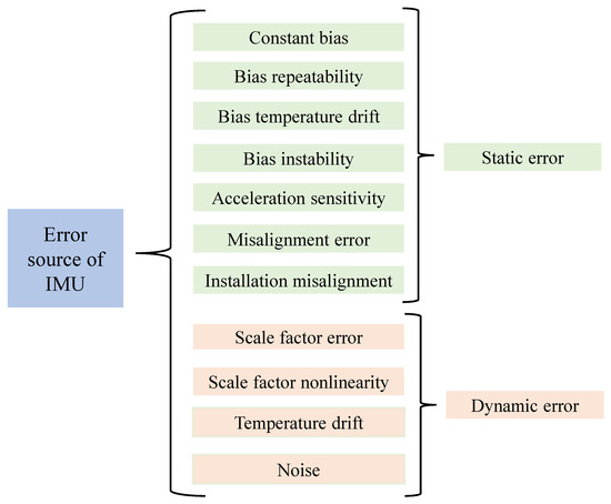
Figure 5.
Sources of error in the IMU.
4. Accuracy-Enhancement Method Based on IMU Calibration
In inertial positioning of underground pipelines, IMU measurements are susceptible to a wide range of errors. In their review, Ru et al. [30] noted that the major errors in MEMS IMUs include zero bias, scale factor, non-orthogonality, and temperature drift. Initial calibration of IMUs is usually carried out in the laboratory, at the factory, or prior to use by determining experimentally and through modeling the inherent error parameters of each sensor of the IMU, including the accelerometers, gyroscopes, and sometimes the magnetometers, among others. The calibration mainly deals with static errors. Calibration mainly deals with static errors, including zero bias, mounting error, non-orthogonal error, etc., which is the key to ensure the inertial positioning accuracy of the pipeline, and the calibration methods of IMU mainly include static calibration of position, Allan variance analysis-assisted calibration, least-squares fitting calibration, static compensation of temperature calibration, deep learning calibration, and non-orthogonal error calibration.
4.1. Zero-Bias Calibration
Zero bias is a constant offset in the output of an IMU even when it is completely stationary, and it is mainly derived from manufacturing errors, temperature drift, and sensor aging. In inertial positioning of underground pipelines, drift error accumulates over time, and zero bias is one of the main sources of drift error. Static zero-bias calibration can reduce drift accumulation, improve attitude solution accuracy, reduce the pressure on subsequent filters, enhance system consistency and repeatability, and adapt to the environmental constraints of underground pipelines.
4.1.1. Position and Attitude Calibration
IMU position calibration is achieved by placing the sensor in a number of known static attitudes. A common hexahedral attitude placement calibration is shown in Figure 6, using gravity or zero angular velocity as a reference to achieve a highly accurate error calibration of the IMU. Fong et al. [47] proposed that the collection of static gyroscope data in the stationary state should last for at least 20 s in order to minimize the change in the mean bias in the subsequent error. Zheng et al. [48] designed a two-position continuous calibration scheme to calibrate the IMU, which can effectively reduce the systematic error and improve the positioning precision and accuracy by calibrating the static zero bias. Zhang et al. [49] improved the calibration accuracy of IMUs by introducing paradigm constraints with sensitivity-optimized design of attitude ensembles in multi-position calibration to jointly estimate the zero bias and scale factor. Ding et al. [50] proposed an improved multi-orientation static calibration method for low-cost MEMS IMUs that, under a gravity-vector norm constraint, jointly estimates the bias and scale factors, enabling efficient calibration without specialized equipment. Most of the zero-bias errors can be compensated by attitude static calibration.
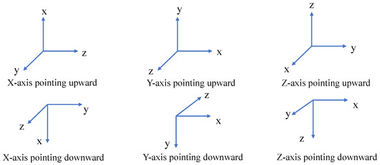
Figure 6.
Six-position attitude placement calibration.
4.1.2. Allan Variance Analysis-Assisted Calibration
Allan variance analysis-assisted calibration measures the cumulative characteristics of noise over time by counting the sensor noise characteristics over a long period of time and calculating the difference between adjacent time averages, thus extracting the random error parameters, such as angular random walk, zero-bias instability, etc., and combining them with the systematic error modeling of the positional calibration to improve the overall accuracy of the low-cost IMU. According to Reference [51], the formula of Allan variance analysis is shown in the formula of (5):
where is the sampling interval, is the average angular velocity or acceleration of the kth segment, and is the ensemble mean. According to Reference [51], the estimated equation for Allan variance in real data is shown in Equation (6):
where is the number of sampling points; is the window size, and ; is the sampling interval time; and is the angle or position accumulation sequence. After the Allan variance analysis is obtained, the Allan equation curve, according to the shape characteristics of the curve, can identify different types of random errors that are random process models and extract their error parameters. And finally, it combines them with error modeling to improve the IMU accuracy. The specific curve analysis is shown in Figure 7. Figure 7, in comparison with the Allan variance analysis results shown in Figure 8, characterizes the IMU noise properties, which can subsequently be used for noise modeling.
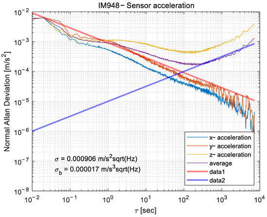
Figure 7.
Noise characteristics of the IM948 ten-axis IMU attitude sensor during a four-hour static test.
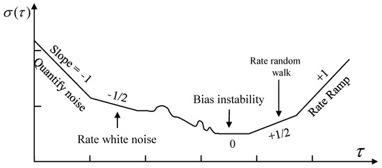
Figure 8.
Example plot of Allan’s variance analysis results.
El-Sheimy et al. [51] modeled the noise characteristics of inertial sensors by Allan variance analysis, which provided theoretical support for subsequent calibration and alignment methods based on noise models. Li et al. [52] combined Allan variance with a Transformer-based network to model and compensate noise in low-cost IMUs, resulting in adaptive correction and enhanced self-calibration accuracy. The Allan variance analysis-assisted calibration can clearly distinguish different types of random errors, and the obtained noise parameters can be directly used in GNSS or KF fusion to improve the system stability.
4.1.3. Least-Squares Fitting Calibration
In IMU calibration, the least-squares method is widely used to estimate parameters such as zero bias, scale factor, and non-orthogonal error of accelerometers and gyroscopes. The basic idea of the least-squares fitting method of calibration is to construct an error model of the sensor output and the true value by collecting multi-attitude static data and obtain the optimal parameters by minimizing the residual sum of squares to achieve the calibration of the IMU. According to Reference [53], the general equation of the least-squares method is shown in Equation (7):
where is the observation vector generally the data of IMU time measurement, including accelerometer or gyroscope output; is the design matrix, which consists of known reference values, such as weight direction or angular velocity; is the vector parameter to be estimated including zero bias of IMU, non-orthogonality error, and so on; denotes the two-parameter number of the vector, and Equation (7) squared denotes the residual sum of squares; and denotes the parameter that minimizes the de-objective function.
Lv [53] used a nonlinear least-squares optimization combined with a truncated singular value decomposition of the observation visibility updating mechanism to achieve a joint calibration of the internal and external parameters of the IMU and the laser radar (Lidar). Lv et al. [54] proposed an ellipsoid fitting algorithm based on a unified error model and using direct least squares to estimate the error model parameters for calibration. After the least-squares calibration, the output of the IMU eliminates or significantly attenuates the deterministic error. Accuracy in attitude determination, velocity estimation, and position estimation is improved, and integration drift is mitigated.
4.1.4. Temperature Compensation Calibration
The core of temperature compensation calibration lies in the modeling and correction of accelerometers and gyroscopes that drift under different temperature conditions to minimize the error, which will be described in detail at this stage from three aspects: measurement, modeling, and calibration. Ali et al. [55] proposed the use of polynomial curve fitting and neural networks for integrated compensation of temperature and acceleration. Cui et al. [56] proposed a proportionality factor temperature compensation method using a temperature varistor circuit to compensate for the drive amplitude operating point to make it change adaptively according to the temperature. Li et al. [57] proposed an intelligent compensation method based on GWO-VMD-TCN-LSTM, which effectively mitigates temperature-induced bias drift and random walk errors, providing a high-precision data-driven solution for MEMS gyroscope temperature calibration; the compensation effect is shown in Figure 9. Zhang et al. [58] proposed a temperature compensated pattern-matching MEMS gyroscope interface-dedicated integrated circuit to improve the temperature adaptability of the gyroscope through temperature compensation.
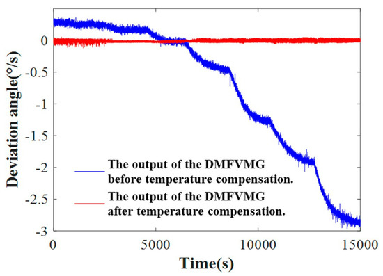
Figure 9.
Comparison of temperature compensation effects (adapted from [57]).
Temperature compensation calibration is one of the key methods to improve the accuracy of IMU by effectively suppressing the drift of sensor output with temperature change through experimental modeling, parameter optimization, and circuit improvement, so that the zero bias and scale factor can be kept stable within the full temperature region.
4.1.5. Deep Learning Calibration
In recent years, deep learning calibration methods have gradually become an important direction in the calibration of low-cost MEMS IMUs, with the core advantage of being able to model complex nonlinear error relationships and having end-to-end or online learning capabilities. Li et al. [59] proposed Calib-Net, which employs a convolutional neural network to model the nonlinear error of low-cost IMUs end-to-end, as shown in Figure 10, and is able to learn the zero-bias and scale-factor compensation relationship directly from the original measurements to achieve efficient calibration under static and quasi-static conditions. Subsequently, Liu et al. [60] proposed LGC-Net, which designs a lightweight convolutional structure to estimate the scale factor and zero-bias error of gyroscopes in real time, thus significantly reducing the computational overhead compared to the traditional methods and making it more suitable for embedded and real-time application scenarios. Then, Pau et al. [61] proposed a Gaussian neural topology-based online learning framework for the time-varying error characteristics of IMUs that is capable of dynamically updating the calibration parameters during operation and maintaining memory efficiency. Finally, Liu et al. [62] proposed to learn the continuous bias dynamics of a six-degree-of-freedom IMU via a hierarchical neural network, which uses a self-supervised approach to model the evolution of the zero bias over time and effectively reduces the cumulative drift problem during long-time operation.
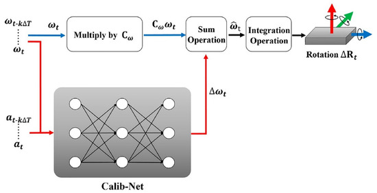
Figure 10.
Dynamic IMU calibration using deep learning networks (adapted from [59]).
From end-to-end error modeling to lightweight real-time networks, to online time-varying calibration, and up to self-supervised hierarchical deviation dynamic learning, these technological evolutions reflect the continuous improvement of IMU calibration methods in terms of accuracy, real-time application, and adaptability, and they also provide new ideas for future high-precision applications of low-cost sensors.
Combining the various calibration methods discussed in the previous section, the position and attitude calibration is calibrated by measuring the IMU output in a variety of static attitudes and estimating the static parameters; the Allan variance analysis-assisted calibration is calibrated by using the Allan variance curve to identify the noise characteristics, such as the zero-bias stability, random walk, etc., and assisting in determining the parameters of the random error model; the least-squares fitting method is used to calibrate by constructing the error equations and minimizing the residual difference between the observed value and the theoretical value, using least-squares optimization to obtain the calibration parameters for calibration; temperature compensation calibration involves establishing a mapping relationship between temperature and zero offset/scale factor by collecting data under different temperature conditions, thereby enabling calibration; and lastly, the deep learning-driven IMU calibration method is able to identify and calibrate the nonlinear errors such as zero bias, scale factor, and temperature drift automatically, thus improving the low cost of calibration. It realizes dynamic online correction, thus improving the accuracy and stability of low-cost IMUs. Table 3 summarizes the previous calibration methods.

Table 3.
Classification of calibration methods.
4.2. Non-Orthogonal Error Calibration
Under ideal conditions, the X, Y, and Z sensitive axes of an accelerometer or gyroscope should be mutually perpendicular, forming an orthogonal three-dimensional coordinate system. However, in reality, sensor manufacturing and assembly cannot achieve absolute precision. Additionally, vibration during motion introduces small angular deviations between the axes. The non-orthogonal error is different from the zero offset, which is a simple constant offset, because it is a matrix problem coupled with the three-axis inputs. Compensating the orthogonal error of the IMU can effectively eliminate the coupling effect of the installation and manufacturing deviation between the sensitive axes of the sensors on the output signals, so as to improve the overall accuracy and stability of the attitude solving and trajectory estimation. According to Reference [6], the mathematical model of non-orthogonal error is usually shown in Equation (8):
where is the non-orthogonal coupling matrix, as shown in (9); denotes the amount of coupling of the x-axis signal to the y-axis; denotes the amount of coupling of the x-axis signal to the z-axis; denotes the amount of coupling of the y-axis signal to the z-axis, and the larger these values are, the worse the orthogonality of the IMU; is the accelerometer scale-factor matrix; is the true ratio vector; is the zero bias of the accelerometer; and is random noise.
There are many calibration methods for non-orthogonal errors, mainly including offline calibration, online calibration, hardware compensation, etc. Zhao et al. [65] proposed a new IMU calibration model based on polarity decomposition, which decomposed the mounting error into non-orthogonal error and misalignment error. Zujevs [66] innovatively proposed a sliding variance discriminant-based interval detection algorithm for static or dynamic scenarios, ensuring that error parameters can be precisely estimated through joint least squares. Sushchenko et al. [67] proposed a procedure for selecting multi-axis MEMS sensors with the same characteristics to create an inertial non-orthogonal measurement instrument based on the analysis of Allan variance evaluation results. Table 4 summarizes the above literature and other sources. After compensating for the non-orthogonal error by the above method, the coupling error between the measurement axes can be significantly reduced, and the attitude solution and navigation and positioning accuracy of the IMU can be improved.

Table 4.
Classification of non-orthogonal error calibration methods.
5. Accuracy Improvement Method Based on IMU Error Compensation
During the operation of the inertial positioning system for underground pipelines, IMUs can dynamically correct the time-accumulated or state-dependent errors, including integral drift, random walk, temperature drift, etc., so that the estimated attitudes, velocities, and positions can be as close as possible to the real values, a process known as the error compensation process. Error compensation relies on the aforementioned calibration results and combines estimation, constraints, fusion, or learning methods to perform dynamic compensation to improve the pipeline positioning accuracy.
5.1. Compensation Mechanisms for External Constraints
The inertial navigation system for underground pipelines has errors such as zero bias and scale factor, which will lead to a gradual increase in the accumulation of position estimation errors over time. The absence of signals in the underground space makes it impossible to use GNSS to assist in the suppression of the accumulation of inertial navigation errors, as the suppression requires the introduction of high-precision external information to carry out the corrections. The start- and end-point position information and the installation of aerial ground marks as an external absolute reference can effectively constrain the inertial-guidance solving trajectory and significantly suppress the accumulated error.
5.1.1. Starting- and Finishing-Position Information
The accurate position information of the pipeline starting point and end point is obtained by GNSS, and the trajectory constraints can effectively reduce the cumulative error by taking the starting-point and end-point position information as an absolute reference, as shown in Figure 11. Wei et al. [72] used the position information of the starting point and end point of the short-distance underground pipeline to construct the trajectory correction matrix, and they achieved high-precision mapping and localization of the underground pipeline. Liu et al. [73] used the position information of both ends to stretch and rotate the calculated trajectory, and they finally obtained the accurate trajectory of the pipeline, thus reducing the positioning error. The problem of rapid accumulation of errors over time is effectively solved by correctly using the position information of the start and end points of the pipeline, thus greatly improving the positioning accuracy.
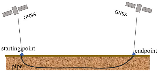
Figure 11.
Schematic diagram of start/finish-location information.
5.1.2. Installation of Ground-Marking Points
For some inertial navigation systems with known position information of the start and end points, the integral drift error can be suppressed with the help of manually assisted measurements or the installation of Aerial Ground Marks (AGMs), the specific form of which is shown in Figure 12. For example, AGMs provide reliable reference coordinates in scenes without GNSS coverage, such as underground pipelines and tunnels. Santana et al. [74] fused inertial and non-inertial sensors using a set of detectable landmarks with a final error of only 0.085%. Guan et al. [75] proposed a Pipeline Inspector Gauge (PIG) positioning system consisting of micro-inertia, AGM, odometer, and pipeline junction (PJ) that is able to achieve accurate positioning in small-diameter pipelines by fusing landmark information. Chowdhury et al. [76] used fusion of IMUs, odometers, and reference stations with known GNSS coordinates for position estimation of pipeline instrumentation. Sahli et al. [77] proposed a method for assisting IMU trajectory correction by deploying an AGM and overall optimization of drifting trajectories by interpolating the fit, which significantly improved inertial navigation accuracy. By installing the AGM, zero setting for system initialization and rigid alignment of post-processing trajectories can be performed.
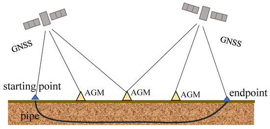
Figure 12.
Installation floor-marking diagram.
In underground pipeline environments without GNSS, positioning errors from pure inertial navigation accumulate over time and distance, exhibiting high sensitivity to sensor drift and operating conditions, resulting in significant overall inaccuracies. Compared to pure inertial methods, AGM provides sparse and absolute reference coordinates for inertial navigation. This enables initialization at start/end points, mid-route anchoring, and post-processing rigid registration. These techniques impose segmented constraints on drift, significantly suppressing integration drift and delivering overall accuracy superior to pure inertial solutions.
For systems that are partially equipped with external positioning conditions for the start and end points, such as the installation of ground marker points or temporary GNSS receiving equipment, researchers often use them as boundary conditions for global drift constraints. Such methods rely on a small amount of external information and can significantly improve the closure consistency of the overall trajectory, but they are difficult to deploy in a completely closed pipeline environment.
5.2. Kinematic Constraints and Compensation Mechanisms for Internal Characteristics
This paper categorizes ZUPT and structural feature recognition into two complementary compensation strategies: constraint-based and feature-based. The former achieves instantaneous pullback of velocity, attitude, and bias during stationary periods or when specific kinematic priors are satisfied—such as zero velocity, zero angular velocity, or incomplete constraints. The latter performs trajectory registration or correction by identifying and matching internal geometric features like pipe bends, tees, and joints, enabling periodic repositioning for long-distance drift correction. Engineering practice often combines both approaches: employing ZUPT to suppress local drift during stationary segments, while utilizing anchor factors for global realignment when traversing landmarks.
5.2.1. Constraint-Based Correction Method
ZUPT is a classical error constraint method in inertial guidance systems and is particularly suitable for intermittent stationary motion scenarios such as gait navigation, pipeline robots, and underground walking carriers [78]. ZUPT is a method of suppressing inertial guidance drift errors by identifying the stationary moment during the motion of a device and using the physical a priori knowledge that the velocity should be zero at this point to update or correct the velocity and attitude information in the navigation solution [79]. ZUPT uses the rate of change in acceleration and angular velocity to determine whether it is stationary or not, and when it is detected as stationary, the current estimated velocity is forced to be corrected to zero, or the state quantity is updated with the help of algorithms such as EKF, which takes the zero velocity as an observation quantity, and the state parameters, such as the zero bias and the proportionality factor, can be corrected for errors as well.
Zha et al. [80] used a combination of machine learning and ZUPT for velocity estimation that significantly reduced the IMU error and maintained the positioning accuracy around 2%. Li et al. [81] achieved more accurate position estimation by using a modified ZUPT in combination with EKF. Kilic [82] embedded ZUPT as a position constraint in the GNSS+INS factor graph framework, which significantly suppressed inertial drift during the start–stop phase through absolute position information. Zhang et al. [83] designed a fiber-optic gyroscope inertial navigation system, combining the zero-velocity detection algorithm with the acceleration motion variance (MV), angular rate energy (ARE), and stance hypothesis optimal estimation (SHOE), and the three-conditional zero velocity detection algorithm of “MV + ARE + SHOE” can effectively suppress the cumulative error of the inertial guidance system and improve the positioning accuracy of the pipe jacking, as shown in Figure 13.
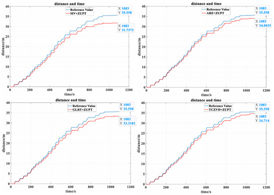
Figure 13.
Comparison of position estimates for each zero-speed detector at different scales of moving and stationary time (adapted from [83]).
ZUPT, as a classical and efficient error constraint method in inertial guidance systems, has become one of the core technologies for suppressing drift errors in intermittent motion scenarios such as gait navigation and pipeline inertial positioning by virtue of its a priori zero-velocity condition.
5.2.2. Feature-Based Correction Method
In pipeline inertial guidance localization, the trajectory needs to be corrected by external or internal feature constraints because the double integration process can easily cause the accumulation of errors. Among them, “structural feature recognition” refers to the use of known geometrical structures in the pipeline or manually set construction points as reference nodes, such as elbows, tees and other pipeline structures, as shown in Figure 14. These feature points are recognized by sensors, and trajectory alignment or correction is performed to suppress navigation errors [84]. If the device exists in a brief stationary state at structures such as elbows and risers, the ZUPT mechanism can be triggered to reset the integration error by forcing the current velocity to zero.
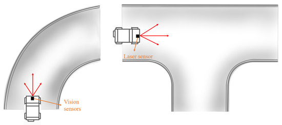
Figure 14.
Schematic diagram of pipeline structure.
Lee et al. [85] proposed a navigation system based on linear laser projection to identify pipe elbow and tee features, which can constrain and reconstruct the positioning trajectory in the post-processing stage by matching the identified nodes with the IMU cumulative distribution. Lee et al. [86] used a method based on structural landmarks and feature recognition of joints and elbows inside the pipeline to improve the pipeline trajectory positioning accuracy by using known or detectable positional feature points as sparse constraints in the navigation system. Guan et al. [87] proposed an estimation method based on the detection of pipe joints to correct the positioning bias of inertial guides due to gyroscope and pitch-angle errors. Kim et al. [88] captured the 3D geometric features of elbows and T-joints by a winding laser scanner at the front end of the robot, which in turn identified the critical nodes in real time and corrected the navigation trajectory by combining IMU and Encoder data. Table 5 summarizes the aforementioned literature, facilitating clearer differentiation between constraint-based and feature-based correction methods.

Table 5.
Feature-based correction method.
In the feature-based correction method, pipe vibration interacts with the sampling/scan frequency, leading to feature distortion, breakage, or aliasing and thus harming detection and localization accuracy. Although robust filters and learning-based compensation are commonly used, systematic public experiments quantifying the vibration–sampling rate–localization error relationship are still missing.
In addition, some studies have also tried to identify “structural feature points” by detecting sudden changes in angular velocity and acceleration, which can be regarded as trajectory anchors or repositioning datums to achieve drift suppression effects similar to ZUPT. These methods do not require external equipment and are suitable for pipeline scenarios with known structures or obvious features.
5.3. Velocity and Attitude Scale-Factor Correction Compensation Mechanisms
In inertial navigation systems, due to the non-ideal nature of gyroscopes and accelerometers, the raw measurement data usually suffers from problems such as scale-factor error and non-orthogonality error, thus leading to systematic deviations in velocity and attitude estimation. The velocity and attitude scale-factor correction mechanism refers to the online or offline estimation and correction of the accelerometer and gyroscope scale factors by analyzing the scale response deviation of the IMU during the inertial guidance solving process, combined with internal kinematic constraints or external references, so as to enhance the velocity and attitude solving accuracy and inhibit the drift accumulated over time. Table 6 shows the main types of scale-factor errors in inertial navigation systems.

Table 6.
Main types of scale-factor errors.
In pipeline inertial guidance positioning, due to long-term operation, ambient temperature changes, or device temperature changes, the scale-factor error will accumulate, leading to serious deviation of positioning from the actual path. Cai et al. [89] improved the multi-position calibration method by introducing an accelerometer nonlinear scaling factor, while a particle swarm optimization algorithm was used in order to solve the complex nonlinear equations. Wang et al. [63] proposed a multi-attitude calibration method based on a nonlinear scale-factor model, which significantly improved the fitting accuracy of the scale factor and the overall solution of the inertial guidance system. As shown in Figure 15, Zhou et al. [90] employed a partial least-squares regression (PLSR) model based on multiple hierarchical correlation parameters to realize self-compensation of the gyroscope scale factor. Zhang et al. [91] proposed an IMU calibration method based on a nonlinear scale-factor model, which can significantly reduce the systematic errors due to nonlinear scale response in low-cost inertial sensors. Zhao et al. [92] used LSTM neural network to learn and model the nonlinear error in the scale factor of the fiber-optic gyroscope (FOG), and they achieved accurate prediction and compensation of the complex nonlinear error, so as to determine the relationship between the input speed and the scale factor. Wei et al. [93] proposed a 30-dimensional Kalman Filter based on a 30-bit attitude calibration scheme to jointly estimate the zero bias, scale factor, and mounting error, thus significantly improving the accuracy of the trajectory solution. Li et al. [94] proposed a new optimization method based on wavelet analysis by combining AGM and odometer information in pipeline centerline positioning. Yang et al. [95] quantified the contribution of the scale-factor error to the final navigation error in terms of covariance decomposition, providing a basis for prioritizing error correction.
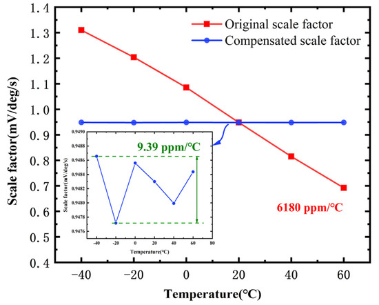
Figure 15.
Influence of temperature on the gyroscope scale factor (adapted from [90]).
In recent years, to address the nonlinear error problem of the scale factor in inertial measurement units, researchers have proposed a variety of modeling and compensation methods to improve system accuracy and stability. Together, they have promoted the development of proportional factor nonlinear modeling methods, from empirical models to data-driven and intelligent prediction. The above methods are summarized in Table 7.

Table 7.
Comparison of IMU scale-factor correction methods.
5.4. Sensor Fusion Compensation Mechanism
In inertial navigation systems, especially in underground pipelines and tunnels lacking external signals, the cumulative errors and drifts generated by IMUs inevitably affect the positioning accuracy. Although front-end solving can initially obtain position and attitude information, it is difficult to meet the high-accuracy positioning requirements by solely relying on front-end processing due to the time-accumulative nature of inertial navigation errors [96]. Therefore, the multi-source sensor fusion method has become a key link to improve the long-term accuracy and stability of the inertial navigation system.
The five more common sensor fusion schemes are vision–inertial fusion, laser–inertial fusion, laser–inertial–visual fusion, magnetometer-assisted inertial guidance, and wheeled odometer + IMU fusion, as shown in Figure 16. There also exist various combinations of IMU, magnetometer, odometer, manometer, vision sensor, UWB, and LiDAR.
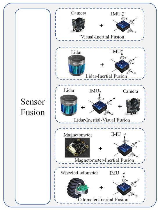
Figure 16.
Common sensor fusion solutions.
Sensor coupling methods can also be broadly categorized as loose or tight coupling, depending on the fusion time of the measurements.
Huang et al. [97] proposed a vision–inertial fusion system for the internal environment of pipelines, tightly coupling IMU and camera data for real-time state estimation. Lu et al. [98] used a Leader–Follower dual-robot fleet form to move through the pipeline, with the Leader carrying LiDAR and the Follower carrying ultrasonic and inertial + odometer sensors. Tian et al. [99] proposed a dense RGB-D SLAM algorithm that combines a monocular camera, IMU, ring laser profiler, and LiDAR that are tightly coupled to overcome the challenges of metric-scale mapping in traditional SLAM methods. Chen et al. [100] proposed an enhanced LIVE-based algorithm integrating LIDAR, camera, and IMU information, and they also used a hybrid optical flow approach based on CNNs to solve the problem of degraded performance of LIDAR and vision systems in pipelines. Liu et al. [101] used information from accelerometers and magnetometers to correct errors in gyroscopes, and structural attitude matrices. Liu et al. [73] introduced a magnetometer to assist the IMU in tracking azimuthal changes to solve the azimuthal drift problem of inertial navigation systems during long-term operation. Zhang et al. [102] implemented a tightly coupled integration of the IMU and the odometer to reduce the errors caused by the odometer mounting attitude error and scale-factor error, and they proposed a new method to eliminate the effect of outliers in the odometer measurements due to wheel slippage. The results of the above literature are summarized in Table 8.

Table 8.
Comparison of sensor fusion methods.
Given that underground pipelines are predominantly located in dark or low-light environments, optical/visual sensors face limitations. Inertial positioning should therefore adopt non-vision-dominant sensor fusion schemes suitable for dark conditions, supplemented by corrections using geometric and topological priors. Table 9 summarizes the applicability of various fusion methods in underground environments. It is evident that under no-light and dusty conditions underground, LiDAR-IMU and Encoder–IMU are the primary solutions; laser–inertial–visual offers gains in limited illumination; visual–inertial is only viable under controlled lighting and clean inner wall conditions; and magnetometer assistance is unsuitable for continuous heading observation in metal pipelines but can be used for event landmark relocalization.

Table 9.
Suitability of different fusion methods in underground environments.
Multi-source sensor fusion has become an important technological approach to achieve high-precision navigation and positioning in complex constrained environments such as pipelines. By introducing external observation information such as magnetometer, odometer, vision, or ultra-wideband, the error caused by drift and noise accumulation of IMU can be effectively suppressed, thus significantly improving the positioning accuracy and robustness of the system. The fusion of data from multiple sensors can achieve complementary advantages, error reduction, and drift suppression, which is one of the core technologies of modern inertial positioning.
5.5. Compensation Mechanisms for Pathway Integration
In pipeline inertial positioning, due to the problem of drift error accumulation over time in the inertial navigation system, path fusion methods are usually used to fuse path information from different sensors or multiple algorithms to improve the overall positioning accuracy and robustness. Common path fusion methods can be roughly divided into three categories: filtering path fusion, optimization path fusion, and deep learning-assisted path fusion, as shown in Figure 17.
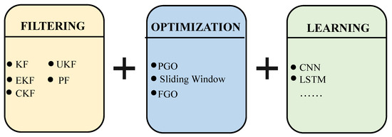
Figure 17.
Convergence strategy schematic.
Filtering methods are the most common means of fusion for inertial navigation by recursively fusing sensor observations with predicted states. Li et al. [104] used temporal forward and inverse Kalman filtering to fuse data from multiple sensors to obtain two trajectories from a single measurement. Niu et al. [105] used a high-speed aerodynamic positioning sphere with a MEMS IMU inside and fused attitude and velocity estimation by constructing an EKF model to effectively suppress the trajectory drift of the MEMS IMU. Yang et al. [106] proposed an improved CKF algorithm for in-tube measurement systems. Doshmanziari et al. [107] proposed the use of the UKF method to achieve high-accuracy estimation of natural gas pipeline leakage location and leakage volume. They compared the estimation accuracy of UKF and EKF, and they found that UKF is better than EKF in both leakage location and leakage volume estimation. Kazeminasab et al. [108] used Particle Filtering (PF) for estimating the type and positional attitude state of the path segment in which it is currently located, greatly enhancing navigation autonomy and applicability. Zhang et al. [109] used a PF + SLAM approach to fuse inertial and pipeline features to solve the problem of pipeline internal structure identification and target localization. The filter-like path fusion method mainly relies on the state estimation theory to achieve dynamic suppression of inertial localization errors and trajectory optimization in underground pipelines.
Optimization-type methods typically model path estimation as an optimization problem, and they achieve high-precision fusion by minimizing reprojection errors or sensor residuals. Mao et al. [110] addressed the persistent problem of noisy interference in conventional inertial positioning by initializing IMU data with graph optimization and performing a large-scale local optimization of historical position and inertial parameters. Liang et al. [111] proposed an enhanced wheel–inertial fusion positioning framework that globally optimizes historical positional attitude and inertial parameters through graph optimization. Zhang et al. [112] used a sliding-window mechanism to analyze IMU positional attitude estimation, detect pipe structural states in short time periods, and introduce these identifications as additional constraints to the EKF. Lu et al. [98] constructed multi-robot positional constraint factors to constrain the relative positions and postures of robots and perform their position and posture corrections with high quality. Chen et al. [113] proposed a factor graph optimization architecture for in-pipeline-assisted INS, which improves the localization accuracy by fusing the information at three levels, involving physical sensor measurements, motion constraints, and scene constraints. The optimization-like path fusion approach improves positioning accuracy and robustness by constructing global or local constraint models to minimize the residuals of multi-sensor observations.
In recent years, Xin et al. [114] combined the Swin Transformer with continuous wavelet transform for structural damage identification, offering a novel approach to incorporating Transformer-based multi-scale feature representation into IMU drift error modeling. Deep learning has been introduced for error modeling, feature extraction, and fusion strategy learning, often embedded as auxiliary modules within traditional pipeline inertial positioning systems. Zhang et al. [115] proposed a CNN+LSTM preprocessing method for IMU data and developed a hybrid deep learning model for accurate classification. Liu et al. [116] utilized an expanded convolutional neural network as the model framework to capture long sequential information dependencies in IMU data for error compensation, improving the regression accuracy of the model. Zhang et al. [117] designed a framework using deep neural networks (DNNs) to compute observable IMU integration terms followed by numerical positional integration and sensor fusion to achieve performance improvement. Deep learning-assisted path fusion improves the accuracy and generalization of pipeline inertial positioning by learning IMU error features or nonlinear relationships between multiple sources of data.
Combining the various methods discussed in the previous section, it is not difficult to conclude that the path fusion method, through the joint optimization and comprehensive use of data information from multiple sensors and the results of multiple algorithms, can not only effectively inhibit the positioning error brought about by the accumulation of drift in the inertial navigation system, but also significantly improve the overall positioning accuracy, system robustness, and environmental adaptability under the complex pipeline environment, thus providing an important technical support and development direction for the realization of long-distance, high-precision pipeline inertial positioning. A comparison of the above literature path fusion methods is shown in Table 10.

Table 10.
Comparison of path fusion methods.
6. Discussions
Based on a review of the extensive literature, this paper innovatively proposes a three-tiered review framework based on “error characteristics–compensation mechanisms–application scenarios”, as illustrated in the Figure 18. It focuses on error characteristics, calibration, and compensation mechanisms, as well as the application scenarios where selected mechanisms are tied to specific operating conditions. It is evident that the drift error in underground pipeline inertial positioning systems primarily stems from IMU zero bias, scale factor, non-orthogonality error, temperature drift, and random noise. These errors accumulate through integration during long-distance positioning, causing position estimates to gradually deviate and significantly degrading accuracy. Compensation methods in existing research primarily include sensor calibration, error modeling, path constraints, external auxiliary information, multi-source fusion, and post-processing optimization [34]. In practice, multiple techniques are often integrated, such as combining calibration with geometric constraints, filtering with deep learning, or embedding external auxiliary information into fusion frameworks to achieve complementary advantages and enhance system robustness [31,32].
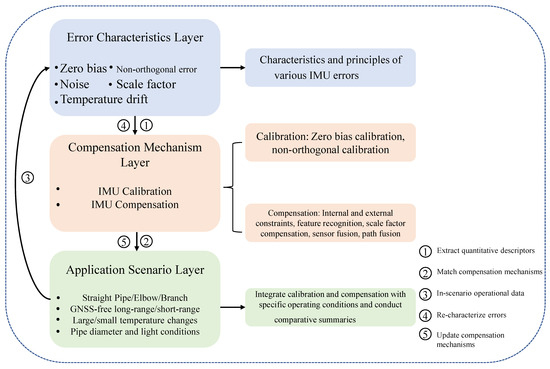
Figure 18.
Three-layer framework visualization roadmap.
However, existing methods still have shortcomings: most validations remain confined to ideal or laboratory conditions, lacking testing in complex pipeline environments; some algorithms are computationally complex, making real-time operation on embedded platforms difficult; insufficient analysis of drift mechanisms results in limited compensation generalization; and the absence of a unified evaluation system hinders cross-comparison of different research results. Therefore, this paper proposes establishing a unified benchmark under a “three-layer framework”: using error factors–mechanism configuration–scenario labels as the smallest unit to perform multi-objective trade-offs between computational power, latency, energy consumption, and accuracy.
Beyond traditional error accuracy metrics, multi-criteria fuzzy reasoning frameworks have been applied in recent years to intelligent condition assessment of structural systems. The triangular intuitionistic fuzzy synthesis model based on analytic networks proposed by Wang et al. [119] provides methodological insights into constructing adaptive reliability evaluation systems for IMU drift compensation algorithms. Future development trends include joint optimization of high-precision and low-cost IMUs, employing nonlinear error modeling, temperature compensation, and adaptive calibration to reduce drift; deep fusion of multi-source heterogeneous information, including visual SLAM, odometry, magnetometry, and pipeline constraints, combined with graph optimization and advanced filtering to achieve high accuracy [33]; and the introduction of intelligent compensation models utilizing deep learning and graph neural networks to advance end-to-end drift prediction, establish standardized evaluation systems, and accelerate engineering applications.
7. Conclusions
With the development of urban pipeline networks, IMUs are increasingly applied in underground pipeline positioning. However, affected by multiple error sources, their accuracy remains insufficient to meet requirements, thus necessitating effective calibration and compensation. Existing research has proposed various methods, but it lacks systematic solutions and a unified evaluation framework. This paper first categorizes IMU error sources into static and dynamic errors, analyzing their characteristics and impacts. It then reviews calibration techniques, ranging from zero-bias and non-orthogonal calibration to deep learning methods, alongside primary compensation mechanisms such as external constraints, zero-velocity updates, structural feature recognition, scale-factor correction, and sensor–path fusion. This paper compares the principles, advantages, disadvantages, and applicable scenarios of each method. Overall, drift error compensation is evolving from single filtering or constraint methods toward multi-source fusion and intelligent approaches. With improvements in sensor accuracy, and with the integration of multi-source fusion and deep learning, future pipeline positioning is expected to achieve higher precision and robustness under complex operating conditions, thereby supporting intelligent pipeline network inspection and maintenance.
Supplementary Materials
The following supporting information can be downloaded at https://www.mdpi.com/article/10.3390/buildings15213904/s1, Figure S1: PRISMA flow diagram; Table S1: Classification of calibration methods; Table S2: Comparison table of sensor fusion methods; Table S3: Comparison table of path fusion methods. Reference [120] is cited in the supplementary materials.
Author Contributions
Z.H., conceptualization, methodology, supervision, project administration, funding acquisition, and writing—review and editing; H.L., investigation, data curation, validation, formal analysis, visualization, and writing—original draft; S.W., methodology, formal analysis, visualization, and writing—review and editing; X.Z., resources, investigation, validation, and writing—review and editing; W.H., data curation, visualization, writing—original draft, and writing—review and editing. All authors have read and agreed to the published version of the manuscript.
Funding
This study was supported by the Chongqing Natural Science Foundation General Project (No. CSTB2025NSCQ-GPX0839); the Science and Technology Research Program of Chongqing Municipal Education Commission (No. KJZD-K202500702); and the Chongqing Municipal Education Commission Program for Collaboration between Universities in Chongqing and Institutes Affiliated with the Chinese Academy of Sciences (No. HZ2021009).
Acknowledgments
We express our sincere gratitude to all colleagues at the Institute of Future Civil Engineering Science and Technology, Chongqing Jiaotong University, whose support and assistance greatly contributed to this project.
Conflicts of Interest
The authors declare no conflicts of interest.
References
- Li, J.; Li, S. Recent advances and applications towards intelligent operation and maintenance of urban pipeline networks. Urban Lifeline 2023, 1, 2. [Google Scholar] [CrossRef]
- Shen, T.; Zhang, H.; Huo, L.; Sun, D. Spatial data fusion model design and research for an underground pipeline in urban environment scene modeling. Appl. Sci. 2024, 14, 6760. [Google Scholar] [CrossRef]
- Huang, G.; Du, S.; Wang, D. GNSS techniques for real-time monitoring of landslides: A review. Satell. Navig. 2023, 4, 5. [Google Scholar] [CrossRef]
- Li, X.; Huang, J.; Li, X.; Shen, Z.; Han, J.; Li, L.; Wang, B. Review of PPP–RTK: Achievements, challenges, and opportunities. Satell. Navig. 2022, 3, 28. [Google Scholar] [CrossRef]
- El-Sheimy, N.; Youssef, A. Inertial sensors technologies for navigation applications: State of the art and future trends. Satell. Navig. 2020, 1, 2. [Google Scholar] [CrossRef]
- Groves, P.D. Navigation using inertial sensors [Tutorial]. IEEE Aerosp. Electron. Syst. Mag. 2015, 30, 42–69. [Google Scholar] [CrossRef]
- Mozafari, S.; Mohammadkarimi, H.; Ghasemi, M.; Parhizkar, M.A.; Mobtaker, M. Analysis of IMU rotation effects on inertial navigation system errors. Navig. J. Inst. Navig. 2025, 72, navi.680. [Google Scholar]
- Liu, X.; Zhou, Q.; Chen, X.; Fan, L.; Cheng, C.-T. Bias-error accumulation analysis for inertial navigation methods. IEEE Signal Process. Lett. 2021, 29, 299–303. [Google Scholar] [CrossRef]
- Zhang, P.; Zhan, X.; Zhang, X.; Zheng, L. Error characteristics analysis and calibration testing for MEMS IMU gyroscope. Aerosp. Syst. 2019, 2, 97–104. [Google Scholar] [CrossRef]
- Łuczak, S.; Zams, M.; Dąbrowski, B.; Kusznierewicz, Z. Tilt sensor with recalibration feature based on MEMS accelerometer. Sensors 2022, 22, 1504. [Google Scholar] [CrossRef]
- Xu, T.; Xu, X.; Ye, H.; Zhang, L. A model-based and efficient parameters correction method for low-cost MEMS IMU. Meas. Sci. Technol. 2024, 36, 015036. [Google Scholar] [CrossRef]
- Vyalkov, A.V.; Vyalkova, T.P. Calibration of IMU MEMS sensors with the use of a manual calibration test rig. Gyroscopy Navig. 2023, 14, 113–128. [Google Scholar] [CrossRef]
- Zhang, Z.; Zhu, G.; Wu, J. Neural network-based temperature drift compensation for MEMS-IMU systems. IEEE Sens. J. 2025, 25, 26353–26363. [Google Scholar] [CrossRef]
- Fang, J.C.; Zhang, X.; Li, J.L. A compensation method for MEMS gyro scale factor error. Acta Aeronaut. Astronaut. Sin. 2010, 31, 350–355. [Google Scholar]
- Siqueira, E.; Azzolin, R.; Botelho, S.; Oliveira, V. Sensors data fusion to navigate inside pipe using Kalman filter. In Proceedings of the 2016 IEEE 21st International Conference on Emerging Technologies and Factory Automation (ETFA), Berlin, Germany, 6–9 September 2016; IEEE: Piscataway, NJ, USA, 2016; pp. 1–5. [Google Scholar]
- Hu, Z.; Gallacher, B. Extended Kalman filtering-based parameter estimation and drift compensation for a MEMS rate-integrating gyroscope. Sens. Actuators A Phys. 2016, 250, 96–105. [Google Scholar] [CrossRef]
- Deng, Z.; Wen, H.; Jiang, L.; Wang, M.; Fan, R. Trajectory reconstruction of subsurface pipes for salt discharge in saline–alkali soils based on an improved EKF and adaptive gradient optimization. Meas. Sci. Technol. 2025, 36, 036147. [Google Scholar] [CrossRef]
- Yang, C.; Shi, W.; Chen, W. Robust M–M unscented Kalman filtering for GPS/IMU navigation. J. Geod. 2019, 93, 1093–1104. [Google Scholar] [CrossRef]
- Okawara, T.; Koide, K.; Oishi, S.; Yokozuka, M.; Banno, A.; Uno, K.; Yoshida, K. Tightly-coupled LiDAR–IMU–wheel odometry with an online neural kinematic model learning via factor graph optimization. Robot. Auton. Syst. 2025, 187, 104929. [Google Scholar] [CrossRef]
- Wu, D.; Chatzigeorgiou, D.; Youcef-Toumi, K.; Ben-Mansour, R. Node localization in robotic sensor networks for pipeline inspection. IEEE Trans. Ind. Inform. 2015, 12, 809–819. [Google Scholar] [CrossRef]
- Sato, H.; Mano, Y.; Ito, F.; Yasui, T.; Okui, M.; Nishihama, R.; Nakamura, T. Proposal for pipeline-shape measurement method based on highly accurate pipeline length measurement by IMU sensor using peristaltic motion characteristics. In Proceedings of the 2020 IEEE/ASME International Conference on Advanced Intelligent Mechatronics (AIM), Boston, MA, USA, 6–9 July 2020; IEEE: Piscataway, NJ, USA, 2020; pp. 874–881. [Google Scholar]
- Liu, S.; Wang, H.; Li, R.; Ji, B. A novel feature identification method of pipeline in-line inspected bending strain based on optimized deep belief network model. Energies 2022, 15, 1586. [Google Scholar] [CrossRef]
- Cai, G.-S.; Lin, H.-Y.; Kao, S.-F. Mobile robot localization using GPS, IMU and visual odometry. In Proceedings of the 2019 International Automatic Control Conference (CACS), Keelung, Taiwan, 13–16 November 2019; IEEE: Piscataway, NJ, USA, 2019. [Google Scholar]
- Zhang, J.; Song, J.; Yang, S.; Guo, H.; Song, A. Absolute localization of underwater pipeline defects based on multimodal information fusion and active perception. IEEE Trans. Instrum. Meas. 2025, 74, 1–13. [Google Scholar] [CrossRef]
- Que, J.; Zheng, E.; Zou, Z. Multi-sensor fusion SLAM method for underground power pipe gallery. J. Phys. Conf. Ser. 2023, 2477, 012070. [Google Scholar] [CrossRef]
- Huang, F.; Wang, Z.; Xing, L.; Gao, C. A MEMS IMU gyroscope calibration method based on deep learning. IEEE Trans. Instrum. Meas. 2022, 71, 1–9. [Google Scholar] [CrossRef]
- Liu, Z.; Shi, D.; Yang, S. A review of initialization methods for visual–inertial navigation systems. J. Natl. Univ. Def. Technol. 2023, 45, 15–26. (In Chinese) [Google Scholar]
- Song, Y.; Liu, N.; Liu, F.; Lei, M.; Qi, W. Deep learning-based temperature error compensation method for MEMS gyroscopes. Chin. J. Sens. Actuators 2022, 35, 92–98. (In Chinese) [Google Scholar]
- Li, Y.; Shi, Z.; Hou, Y. New advances in pedestrian inertial positioning: Neural network-based methods, performance, and prospects. Acta Autom. Sin. 2025, 51, 271–286. (In Chinese) [Google Scholar]
- Ru, X.; Gu, N.; Shang, H.; Zhang, H. MEMS inertial sensor calibration technology: Current status and future trends. Micromachines 2022, 13, 879. [Google Scholar] [CrossRef]
- Han, S.; Meng, Z.; Omisore, O.; Akinyemi, T.; Yan, Y. Random error reduction algorithms for MEMS inertial sensor accuracy improvement—A review. Micromachines 2020, 11, 1021. [Google Scholar] [CrossRef] [PubMed]
- Chen, C.; Pan, X. Deep learning for inertial positioning: A survey. IEEE Trans. Intell. Transp. Syst. 2024, 25, 10506–10523. [Google Scholar] [CrossRef]
- Fan, Z.; Zhang, L.; Wang, X.; Shen, Y.; Deng, F. LiDAR, IMU, and camera fusion for simultaneous localization and mapping: A systematic review. Artif. Intell. Rev. 2025, 58, 174. [Google Scholar] [CrossRef]
- Luo, X.; Zhao, Y.; Li, M.; Zhou, H.; Wang, F.; Du, Y.; Jiang, W.; Zhu, J.; Zhao, Y. Underground pipeline inspection and monitoring in mountainous areas: A state-of-the-art review and future perspectives. Tunn. Undergr. Space Technol. 2025, 164, 106783. [Google Scholar] [CrossRef]
- Wang, Q.; Li, Y.; Niu, X. Thermal calibration procedure and thermal characterisation of low-cost inertial measurement units. J. Navig. 2016, 69, 373–390. [Google Scholar] [CrossRef]
- Unsal, D.; Demirbas, K. Estimation of deterministic and stochastic IMU error parameters. In Proceedings of the 2012 IEEE/ION Position, Location and Navigation Symposium, Myrtle Beach, SC, USA, 23–26 April 2012; IEEE: Piscataway, NJ, USA, 2012; pp. 862–868. [Google Scholar]
- Aggarwal, P.; Syed, Z.; El-Sheimy, N. Thermal calibration of low-cost MEMS sensors for land vehicle navigation system. In Proceedings of the VTC Spring 2008—IEEE Vehicular Technology Conference, Singapore, 11–14 May 2008; IEEE: Piscataway, NJ, USA, 2008; pp. 2859–2863. [Google Scholar]
- Niu, X.; Li, Y.; Zhang, H.; Wang, Q.; Ban, Y. Fast thermal calibration of low-grade inertial sensors and inertial measurement units. Sensors 2013, 13, 12192–12217. [Google Scholar] [CrossRef] [PubMed]
- Huang, G.-L.; Tong, S.-Q.; Sun, Q.; Pian, Z. Research on calibration and parameter compensation of MEMS inertial sensors based on error analysis. In Proceedings of the 2012 Fifth International Symposium on Computational Intelligence and Design, Hangzhou, China, 28–29 October 2012; IEEE: Piscataway, NJ, USA, 2012; Volume 1, pp. 325–329. [Google Scholar]
- Barrau, A.; Bonnabel, S. A mathematical framework for IMU error propagation with applications to preintegration. In Proceedings of the 2020 IEEE International Conference on Robotics and Automation (ICRA), Paris, France, 31 May–31 August 2020; IEEE: Piscataway, NJ, USA, 2020; pp. 5732–5738. [Google Scholar]
- Long, Y.; Liu, Z.; Hao, C.; Ayazi, F. MEMS gyroscope multi-feature calibration using machine learning technique. arXiv 2024, arXiv:2410.07519. [Google Scholar] [CrossRef]
- Lou, Q.; Li, D.; Li, H.; Liu, C.; Lan, T.; Tan, Z.; Yu, X. A system-level calibration method for INS: Simultaneous compensation of accelerometer asymmetric errors and second-order temperature-related errors. IEEE Trans. Instrum. Meas. 2025, 74, 1–9. [Google Scholar] [CrossRef]
- Chang, L.; Wu, W.; Gu, Y.; Cui, J.; Miao, T. A system-level calibration method with gyroscope g-sensitivity for MEMS-IMU. In Proceedings of the International Conference on Guidance, Navigation and Control, Changsha, China, 9–11 August 2024; Springer Nature: Singapore, 2024; pp. 192–202. [Google Scholar]
- Zhao, G.; Tan, M.; Guo, Q.; Wu, C. An improved system-level calibration method of strapdown inertial navigation system based on matrix factorization. IEEE Sens. J. 2022, 22, 14986–14996. [Google Scholar] [CrossRef]
- El-Diasty, M.; Pagiatakis, S. Calibration and stochastic modelling of inertial navigation sensor errors. J. Glob. Position. Syst. 2008, 7, 170–182. [Google Scholar] [CrossRef]
- Guerrier, S.; Molinari, R.; Stebler, Y. Theoretical limitations of Allan variance-based regression for time series model estimation. IEEE Signal Process. Lett. 2016, 23, 597–601. [Google Scholar] [CrossRef]
- Fong, W.T.; Ong, S.K.; Nee, A.Y.C. Methods for in-field user calibration of an inertial measurement unit without external equipment. Meas. Sci. Technol. 2008, 19, 085202. [Google Scholar] [CrossRef]
- Zheng, T.; Xu, A.; Xu, X.; Liu, M. Modeling and compensation of inertial sensor errors in measurement systems. Electronics 2023, 12, 2458. [Google Scholar] [CrossRef]
- Zhang, H.; Wu, Y.; Wu, W.; Wu, M.; Hu, X. Improved multi-position calibration for inertial measurement units. Meas. Sci. Technol. 2009, 21, 015107. [Google Scholar] [CrossRef]
- Ding, Z.; Cai, H.; Yang, H. An improved multi-position calibration method for low-cost micro-electro-mechanical systems inertial measurement units. Proc. Inst. Mech. Eng. Part G J. Aerosp. Eng. 2015, 229, 1919–1930. [Google Scholar] [CrossRef]
- El-Sheimy, N.; Hou, H.; Niu, X. Analysis and modeling of inertial sensors using Allan variance. IEEE Trans. Instrum. Meas. 2008, 57, 140–149. [Google Scholar] [CrossRef]
- Li, Y.; Liu, B.; Zhuo, W.; Liu, S.; Tian, L.; Huang, G.; Sun, J.; Huang, J. Noise modeling and compensation of low-cost IMU based on Allan variance–Transformer model. In Proceedings of the 2025 IEEE 34th Wireless and Optical Communications Conference (WOCC), Macao, Chian, 20–22 May 2025; IEEE: Piscataway, NJ, USA, 2025; pp. 446–450. [Google Scholar]
- Lv, J.; Zuo, X.; Hu, K.; Xu, J.; Huang, G.; Liu, Y. Observability-aware intrinsic and extrinsic calibration of LiDAR–IMU systems. IEEE Trans. Robot. 2022, 38, 3734–3753. [Google Scholar] [CrossRef]
- Lv, C.; Chen, X.; Huang, H.; Zhou, Z. Study on calibration method for tri-axial accelerometers. In Proceedings of the 2015 IEEE Metrology for Aerospace (MetroAeroSpace), Benevento, Italy, 4–5 June 2015; IEEE: Piscataway, NJ, USA, 2015; pp. 15–20. [Google Scholar]
- Ali, M. Compensation of temperature and acceleration effects on MEMS gyroscope. In Proceedings of the 2016 13th International Bhurban Conference on Applied Sciences and Technology (IBCAST), Islamabad, Pakistan, 12–16 January 2016; IEEE: Piscataway, NJ, USA, 2016; pp. 274–279. [Google Scholar]
- Cui, M.; Huang, Y.; Wang, W.; Cao, H. MEMS gyroscope temperature compensation based on drive mode vibration characteristic control. Micromachines 2019, 10, 248. [Google Scholar] [CrossRef]
- Li, A.; Cui, K.; An, D.; Liu, X.; Wang, Y. Multi-Frame Vibration MEMS Gyroscope Temperature Compensation Based on Combined GWO-VMD-TCN-LSTM Algorithm. Micromachines 2024, 15, 1379. [Google Scholar] [CrossRef]
- Zhang, H.; Chen, W.; Yin, L.; Fu, Q. Design of MEMS gyroscope interface ASIC with on-chip temperature compensation. Measurement 2023, 220, 113331. [Google Scholar] [CrossRef]
- Li, R.; Fu, C.; Yi, W.; Yi, X. Calib-Net: Calibrating the low-cost IMU via deep convolutional neural network. Front. Robot. AI 2022, 8, 772583. [Google Scholar] [CrossRef] [PubMed]
- Liu, Y.; Liang, W.; Cui, J. LGC-Net: A lightweight gyroscope calibration network for efficient attitude estimation. arXiv 2022, arXiv:2209.08816. [Google Scholar] [CrossRef]
- Pau, D.P.; Tognocchi, S.; Marcon, M. Learning online MEMS calibration with time-varying and memory-efficient Gaussian neural topologies. Sensors 2025, 25, 3679. [Google Scholar] [CrossRef]
- Liu, B.; Lin, T.Y.; Zhang, W.; Ghaffari, M. Debiasing 6-DOF IMU via hierarchical learning of continuous bias dynamics. arXiv 2025, arXiv:2504.09495. [Google Scholar] [CrossRef]
- Wang, Z.; Cheng, X.; Fu, J. Optimized multi-position calibration method with nonlinear scale factor for inertial measurement units. Sensors 2019, 19, 3568. [Google Scholar] [CrossRef]
- Wang, Z.; Xie, Y.; Yu, X.; Fan, H.; Wei, G.; Wang, L.; Fan, Z.; Wang, G.; Luo, H. A system-level calibration method including temperature-related error coefficients for a strapdown inertial navigation system. Meas. Sci. Technol. 2021, 32, 115117. [Google Scholar] [CrossRef]
- Zhao, G.; Tan, M.; Wang, X.; Liang, W.; Gao, S.; Chen, Z. Research on IMU calibration model based on polar decomposition. Micromachines 2023, 14, 697. [Google Scholar] [CrossRef] [PubMed]
- Zujevs, A.; Vecins, V.; Korsunovs, A. A method for static and dynamic interval detection within the IMU calibration procedure. In Proceedings of the 2019 International Conference on Informatics in Control, Automation and Robotics (ICINCO), Prague, Czech Republic, 29–31 July 2019; pp. 746–751. [Google Scholar]
- Sushchenko, O.; Bezkorovainyi, Y. Non-orthogonal configuration of MEMS sensors analysis based on Allan variance. In Proceedings of the 2024 IEEE 42nd International Conference on Electronics and Nanotechnology (ELNANO), Kiev, Ukraine, 13–16 May 2024; IEEE: Piscataway, NJ, USA, 2024; pp. 549–554. [Google Scholar]
- Hegazy, S.A.E.H.; Mahmoud, A.M.; Kamel, A.M.; Arafa, I.I.; Elhalwagy, Y.Z. Calibration and compensation of scale factor non-linearity and non-orthogonality errors for dynamically tuned gyroscope (DTG). In Proceedings of the 2020 12th International Conference on Electrical Engineering (ICEENG), Cairo, Egypt, 7–9 July 2020; IEEE: Piscataway, NJ, USA, 2020; pp. 371–376. [Google Scholar]
- Kalikhman, D.M.; Turkin, V.A. Techniques for inspecting IMUs with nonorthogonal orientation of their sensitive axes. Gyroscopy Navig. 2023, 14, 305–319. [Google Scholar] [CrossRef]
- Cui, J.; Zhao, Q. Bias thermal stability improvement of MEMS gyroscope with quadrature motion correction and temperature self-sensing compensation. Micro Nano Lett. 2020, 15, 234–238. [Google Scholar] [CrossRef]
- Tatar, E.; Alper, S.E.; Akin, T. Quadrature-error compensation and corresponding effects on the performance of fully decoupled MEMS gyroscopes. J. Microelectromechanical Syst. 2012, 21, 656–667. [Google Scholar] [CrossRef]
- Wei, X.; Fan, S.; Zhang, Y.; Chang, L.; Wang, G.; Shen, F. Positioning algorithm of MEMS pipeline inertial locator based on dead reckoning and information multiplexing. Electronics 2022, 11, 2931. [Google Scholar] [CrossRef]
- Liu, J.; Liu, X.; Yang, W.; Pan, S. Investigating the survey instrument for the underground pipeline with inertial sensor and dead reckoning method. Rev. Sci. Instrum. 2021, 92, 025112. [Google Scholar] [CrossRef] [PubMed]
- Santana, D.D.S.; Maruyama, N.; Furukawa, C.M. Estimation of trajectories of pipeline PIGs using inertial measurements and non-linear sensor fusion. In Proceedings of the 2010 9th IEEE/IAS International Conference on Industry Applications (INDUSCON 2010), Sao Paulo, Brazil, 8–10 May 2010; IEEE: Piscataway, NJ, USA, 2010; pp. 1–6. [Google Scholar]
- Guan, L.; Xu, X.; Gao, Y.; Liu, F.; Rong, H.; Wang, M.; Noureldin, A. Micro-inertial-aided high-precision positioning method for small-diameter PIG navigation. In Advances in Human and Machine Navigation Systems; IntechOpen: London, UK, 2018. [Google Scholar]
- Chowdhury, S.; Abdel-Hafez, M.F. Pipeline inspection gauge position estimation using inertial measurement unit, odometer, and a set of reference stations. ASCE–ASME J. Risk Uncertain. Eng. Syst. Part B Mech. Eng. 2016, 2, 021001. [Google Scholar] [CrossRef]
- Sahli, H.; Moussa, A.; Noureldin, A.; El-Sheimy, N. Small pipeline trajectory estimation using MEMS-based IMU. In Proceedings of the 27th International Technical Meeting of the Satellite Division of the Institute of Navigation (ION GNSS+ 2014), Tampa, FL, USA, 8–12 September 2014; pp. 154–161. [Google Scholar]
- Cai, Q.; Yang, G.; Song, N.; Pan, J.; Liu, Y. An online smoothing method based on reverse navigation for ZUPT-aided INSs. J. Navig. 2017, 70, 342–358. [Google Scholar] [CrossRef]
- Wang, Y.; Chernyshoff, A.; Shkel, A.M. Study on estimation errors in ZUPT-aided pedestrian inertial navigation due to IMU noises. IEEE Trans. Aerosp. Electron. Syst. 2019, 56, 2280–2291. [Google Scholar] [CrossRef]
- Zha, J.; Chen, J.; Ren, Q.; Ma, Y.; Wang, N. Enhancing IMU navigation systems with LSTM and ZUPT: A machine learning approach. In Proceedings of the 2024 9th International Conference on Integrated Circuits and Microsystems (ICICM), Wuhan, China, 25–27 October 2024; IEEE: Piscataway, NJ, USA, 2024; pp. 560–564. [Google Scholar]
- Li, J.; Zhou, X.; Qiu, S.; Mao, Y.; Wang, Z.; Loo, C.K.; Liu, X. Learning-based stance phase detection and multisensor data fusion for ZUPT-aided pedestrian dead-reckoning system. IEEE Internet Things J. 2023, 11, 5899–5911. [Google Scholar] [CrossRef]
- Kilic, C.; Das, S.; Gutierrez, E.; Watson, R.; Gross, J. ZUPT-aided GNSS factor graph with inertial navigation integration for wheeled robots. In Proceedings of the 34th International Technical Meeting of the Satellite Division of the Institute of Navigation (ION GNSS+ 2021), Online, 20–24 September 2021; pp. 3285–3293. [Google Scholar]
- Zhang, W.; Wang, L.; Zu, Y. The zero-velocity correction method for pipe jacking automatic guidance system based on fiber optic gyroscope. Sensors 2024, 24, 5911. [Google Scholar] [CrossRef]
- Choi, Y.S.; Kim, H.M.; Mun, H.M.; Lee, Y.G.; Choi, H.R. Recognition of pipeline geometry by using monocular camera and PSD sensors. Intell. Serv. Robot. 2017, 10, 213–227. [Google Scholar] [CrossRef]
- Lee, D.H.; Moon, H.; Choi, H.R. Autonomous navigation of in-pipe working robot in unknown pipeline environment. In Proceedings of the 2011 IEEE International Conference on Robotics and Automation (ICRA), Shanghai, China, 9–13 May 2011; IEEE: Piscataway, NJ, USA, 2011; pp. 1559–1564. [Google Scholar]
- Lee, D.H.; Moon, H.; Koo, J.C.; Choi, H.R. Map building method for urban gas pipelines based on landmark detection. Int. J. Control. Autom. Syst. 2013, 11, 127–135. [Google Scholar] [CrossRef]
- Guan, L.; Cong, X.; Sun, Y.; Gao, Y.; Iqbal, U.; Noureldin, A. Enhanced MEMS SINS-aided pipeline surveying system by pipeline junction detection in small-diameter pipeline. IFAC-PapersOnLine 2017, 50, 3560–3565. [Google Scholar] [CrossRef]
- Kim, S.H.; Lee, S.J.; Kim, S.W. Weaving laser vision system for navigation of mobile robots in pipeline structures. IEEE Sens. J. 2018, 18, 2585–2591. [Google Scholar] [CrossRef]
- Cai, Q.; Song, N.; Yang, G.; Liu, Y. Accelerometer calibration with nonlinear scale factor based on multi-position observation. Meas. Sci. Technol. 2013, 24, 105002. [Google Scholar] [CrossRef]
- Zhou, R.; Cui, R.; An, D.; Shen, C.; Bai, Y.; Cao, H. Integrating Multiple Hierarchical Parameters to Achieve the Self-Compensation of Scale Factor in a Micro-Electromechanical System Gyroscope. Micromachines 2024, 15, 1385. [Google Scholar] [CrossRef]
- Zhang, X.; Zhou, C.; Chao, F.; Lin, C.-M.; Yang, L.; Shang, C.; Shen, Q. Low-cost inertial measurement unit calibration with nonlinear scale factors. IEEE Trans. Ind. Inform. 2021, 18, 1028–1038. [Google Scholar] [CrossRef]
- Zhao, S.; Zhou, Y.; Shu, X. Study on nonlinear error calibration of fiber optical gyroscope scale factor based on LSTM. Measurement 2022, 190, 110783. [Google Scholar] [CrossRef]
- Wei, Q.; Zha, F.; He, H.; Li, B. An improved system-level calibration scheme for rotational inertial navigation systems. Sensors 2022, 22, 7610. [Google Scholar] [CrossRef] [PubMed]
- Li, R.; Wang, Z.; Chen, P. Development of a method of pipeline bending strain measurement based on micro-electromechanical systems inertial measurement unit. Sci. Prog. 2020, 103, 0036850420925231. [Google Scholar] [CrossRef]
- Yang, X.; Yan, G.; Liu, F.; Guan, B.; Li, S. Analysis method of strapdown inertial navigation error distribution based on covariance matrix decomposition. In Proceedings of the 2022 41st Chinese Control Conference (CCC), Hefei, China, 25–27 July 2022; IEEE: Piscataway, NJ, USA, 2022; pp. 3462–3467. [Google Scholar]
- Hyun, D.; Yang, H.S.; Park, H.S.; Kim, H.-J. Dead-reckoning sensor system and tracking algorithm for 3-D pipeline mapping. Mechatronics 2010, 20, 213–223. [Google Scholar] [CrossRef]
- Huang, Y.; Yuan, J.; Du, L.; Bao, S.; Hu, Z.; Zhang, H. Pipe-VINS: A robust, real-time visual–inertial state estimator in pipe environment. In Proceedings of the 2023 IEEE International Conference on Robotics and Biomimetics (ROBIO), Samui, Thailand, 4–9 December 2023; IEEE: Piscataway, NJ, USA, 2023; pp. 1–6. [Google Scholar]
- Lu, D.; Zhang, Y.; Gong, Z.; Wu, T. A SLAM method based on multi-robot cooperation for pipeline environments underground. Sustainability 2022, 14, 12995. [Google Scholar] [CrossRef]
- Tian, T.; Wang, L.; Yan, X.; Ruan, F.; Aadityaa, G.J.; Choset, H.; Li, L. Visual–inertial–laser–LiDAR (VILL) SLAM: Real-time dense RGB-D mapping for pipe environments. In Proceedings of the 2023 IEEE/RSJ International Conference on Intelligent Robots and Systems (IROS), Detroit, MI, USA, 1–5 October 2023; IEEE: Piscataway, NJ, USA, 2023; pp. 1525–1531. [Google Scholar]
- Chen, X.; Zhang, Y.; Zhu, X.; Liu, C.; Wang, S.; Deng, X. Multi-sensor fusion for 3D reconstruction of urban pipeline interior using the enhanced R3LIVE algorithm. IEEE Sens. J. 2025, 25, 15830–15841. [Google Scholar] [CrossRef]
- Liu, K.; Zhuang, X.; Xiao, L. Location detection of underground pipeline based on multi-sensor fusion. In Proceedings of the 2017 13th International Conference on Natural Computation, Fuzzy Systems and Knowledge Discovery (ICNC-FSKD), Guilin, China, 29–31 July 2017; IEEE: Piscataway, NJ, USA, 2017; pp. 2953–2957. [Google Scholar]
- Zhang, P.; Hancock, C.M.; Lau, L.; Roberts, G.W.; de Ligt, H. Low-cost IMU and odometer tightly coupled integration with robust Kalman filter for underground 3-D pipeline mapping. Measurement 2019, 137, 454–463. [Google Scholar] [CrossRef]
- Wang, Q.; Cai, M.; Guo, Z. An enhanced positioning technique for underground pipeline robot based on inertial sensor/wheel odometer. Measurement 2023, 206, 112298. [Google Scholar] [CrossRef]
- Li, P.; Wang, L.; Zu, Y.; Bai, X.; Hu, Y. Multi-sensor fusion method based on FFR–FK for 3D trajectory measurement of underground pipelines. Tunn. Undergr. Space Technol. 2023, 141, 105344. [Google Scholar] [CrossRef]
- Niu, X.; Hu, J.; Chen, Q.; Zhao, D. A MEMS IMU-based air-propelled positioning ball for small-diameter underground pipelines localization. IEEE Sens. J. 2025, 25, 18257. [Google Scholar] [CrossRef]
- Yang, Y.; Bin, L.; Xinjie, W.; Lijian, Y. Application of adaptive cubature Kalman filter to in-pipe survey system for 3D small-diameter pipeline mapping. IEEE Sens. J. 2020, 20, 6331–6337. [Google Scholar] [CrossRef]
- Doshmanziari, R.; Khaloozadeh, H.; Nikoofard, A. Unscented Kalman filter in gas pipeline leakage magnitude estimation and localization. In Proceedings of the 2019 6th International Conference on Control, Instrumentation and Automation (ICCIA), Sanandaj, Iran, 30–31 October 2019; IEEE: Piscataway, NJ, USA, 2019; pp. 1–6. [Google Scholar]
- Kazeminasab, S.; Janfaza, V.; Razavi, M.; Banks, M.K. Smart navigation for an in-pipe robot through multi-phase motion control and particle filtering method. In Proceedings of the 2021 IEEE International Conference on Electro Information Technology (EIT), Online, 13–15 May 2021; IEEE: Piscataway, NJ, USA, 2021; pp. 342–349. [Google Scholar]
- Zhang, H.; Ding, Z.; Zhou, L.; Wang, D. Particle filtering SLAM algorithm for urban pipe leakage detection and localization. Wirel. Netw. 2024, 30, 6809–6820. [Google Scholar] [CrossRef]
- Mao, J.; Song, W.; Liang, H.; Xia, F.; Zhang, C. Graph-optimized encoder–IMU fusion for robust pipeline robot localization in confined spaces. IEEE Trans. Instrum. Meas. 2025, 74, 1–12. [Google Scholar] [CrossRef]
- Liang, H.; Zhang, S.; Mao, J.; Zhang, C. Wheel–inertial fusion localization strategy for mobile robots in confined pipeline spaces. In Proceedings of the 2023 5th International Conference on Robotics, Intelligent Control and Artificial Intelligence (RICAI), Hangzhou, China, 1–3 December 2023; IEEE: Piscataway, NJ, USA, 2023; pp. 108–113. [Google Scholar]
- Zhang, S.; Dubljevic, S. Trajectory determination for pipelines using an inspection robot and pipeline features. Metrol. Meas. Syst. 2021, 28, 439–453. [Google Scholar] [CrossRef]
- Chen, Q.; Li, S.; Chen, Q.; Niu, X.; Wang, Y.; Jiang, W. Multi-level information fusion enhanced by scene constraint: Key to improve autonomous positioning accuracy in urban underground pipeline using MEMS inertial sensors. Measurement 2025, 239, 115442. [Google Scholar] [CrossRef]
- Xin, J.; Tao, G.; Tang, Q.; Zou, F.; Xiang, C. Structural damage identification method based on Swin Transformer and continuous wavelet transform. Intell. Robot. 2024, 4, 200–215. [Google Scholar] [CrossRef]
- Zhang, D.; Liu, X.; Fu, M.; Liu, S.; Shao, J.; Chen, P.; Li, R.; Fu, K.; Cheng, J. A novel local deformation pipe section identification method via IMU detection data and hybrid deep learning model. Mech. Syst. Signal Process. 2025, 224, 112091. [Google Scholar] [CrossRef]
- Liu, M.; Wang, W.; Shi, Z.; Xie, L.; Chen, W.; Yan, Y.; Yin, E. Deep learning-based IMU errors compensation with dynamic receptive field mechanism. In Proceedings of the International Conference on Guidance, Navigation and Control, Changsha, China, 9–11 August 2024; Springer Nature: Singapore, 2024; pp. 95–105. [Google Scholar]
- Zhang, M.; Zhang, M.; Chen, Y.; Li, M. IMU data processing for inertial-aided navigation: A recurrent neural network based approach. In Proceedings of the 2021 IEEE International Conference on Robotics and Automation (ICRA), Xi’an, China, 30 May–5 June 2021; IEEE: Piscataway, NJ, USA, 2021; pp. 3992–3998. [Google Scholar]
- Afshar, I.H.; Delavar, M.R.; Moshiri, B. A novel constrained filter integrated with an extended Kalman filter in underground pipeline navigation using MEMS IMU. Gyroscopy Navig. 2022, 13, 7–22. [Google Scholar] [CrossRef]
- Wang, C.; Tang, Q.; Wu, B.; Jiang, Y.; Xin, J. Intelligent bridge monitoring system operational status assessment using analytic network-aided triangular intuitionistic fuzzy comprehensive model. Intell. Robot. 2025, 5, 378–403. [Google Scholar] [CrossRef]
- Tricco, A.C.; Lillie, E.; Zarin, W.; O’Brien, K.K.; Colquhoun, H.; Levac, D.; Moher, D.; Peters, M.D.J.; Horsley, T.; Weeks, L.; et al. PRISMA Extension for Scoping Reviews (PRISMAScR): Checklist and Explanation. Ann. Intern Med. 2018, 169, 467–473. [Google Scholar] [CrossRef] [PubMed]
Disclaimer/Publisher’s Note: The statements, opinions and data contained in all publications are solely those of the individual author(s) and contributor(s) and not of MDPI and/or the editor(s). MDPI and/or the editor(s) disclaim responsibility for any injury to people or property resulting from any ideas, methods, instructions or products referred to in the content. |
© 2025 by the authors. Licensee MDPI, Basel, Switzerland. This article is an open access article distributed under the terms and conditions of the Creative Commons Attribution (CC BY) license (https://creativecommons.org/licenses/by/4.0/).