1. Introduction
In modern structural engineering, the demand for high-strength, lightweight, and large-span structures has far exceeded the capacity of conventional single-material components. Columns, as primary load-carrying members, are crucial in ensuring structural safety and functionality. Traditional reinforced concrete columns, while widely used, suffer from drawbacks such as large self-weight, limited ductility, and vulnerability to corrosion in aggressive environments; their limited ductility also increases the risk of collapse under scenarios like column removal [
1,
2]. Consequently, considerable research attention has shifted toward hybrid columns that integrate multiple materials to combine their respective advantages, with the aim of improving structural performance and durability. Among these, fiber-reinforced polymer (FRP) composites have emerged as highly promising due to their excellent corrosion resistance, superior tensile strength, and light weight. When used as external confining tubes for concrete columns, FRP materials effectively provide lateral confinement, creating a triaxial compressive stress state in the core concrete. This confinement greatly enhances both the compressive strength and ductility of the concrete. Early research by Harmon et al. [
3,
4] demonstrated the benefits of carbon FRP (CFRP) and glass FRP (GFRP) jackets, revealing that confined concrete could achieve compressive strength increases of up to seven times compared to unconfined specimens. Numerous subsequent studies have examined the behavior of FRP-confined solid concrete columns, emphasizing variables such as the FRP jacket type used for confinement [
5,
6,
7,
8], FRP thickness [
9,
10], the cross-section geometry of columns confined with FRP [
11,
12,
13], and concrete strength [
14,
15,
16].
Further advancing these hybrid columns, Teng and his group [
17,
18] introduced the double-skin tubular column (DSTC) concept, comprising an external FRP tube and an internal steel tube with concrete infilling the annular space between them, as schematically shown in
Figure 1a. This type of hybrid columns combines the confinement effects of both the inner steel tube and the outer FRP tube. The concrete core is simultaneously confined externally by the FRP and internally by the steel tube, resulting in enhanced axial load-carrying capacity, improved ductility, and delayed local buckling of the inner steel tube. Since then, DSTCs have been extensively investigated in terms of their static and dynamic performances. For example, Wang et al. [
19] incorporated UHPC as the infilling material in DSTCs. The experimental results demonstrated that the DSTCs with UHPC had good ductility under eccentric compression, indicating that it is a promising form for engineering use in practice. Similarly, Khusru et al. [
20,
21] used rubberized concrete as the infilling material in DSTCs, which were shown to provide a promising sustainable solution with greater compressive capacity. Qian et al. [
22,
23] conducted both axial compression and lateral cyclic loading tests on DSTCs. The experimental findings revealed that the sandwich concrete was effectively confined by both the inner steel tube and the outer FRP tube. In turn, the concrete delayed the local buckling of the inner steel tube. Consequently, the bearing capacity, ductility, and seismic performance of DSTCs have been significantly enhanced. Furthermore, Wong et al. [
24] conducted comparative experiments involving FRP-confined solid cylinders (FCSCs), FRP-confined hollow cylinders (FCHCs), and short DSTCs. The results demonstrated that the incorporation of an inner steel tube nearly fully compensated for the reduction in FRP confinement effect attributable to the presence of the internal cavity. Yu et al. [
25,
26] advanced a stress–strain model specifically for concrete within DSTCs based on existing experimental data and finite element simulations considering strain gradient effect and further experimentally verified the excellent performance of DSTCs under eccentric compression. Beyond compression performance, DSTCs have also shown excellent bending [
27] and seismic performance [
28,
29].
Based on the DSTC principle, numerous variants have been proposed to further optimize hybrid columns. For instance, Feng et al. [
30] developed a type of steel–concrete-FRP–concrete columns (SCFCs) that utilized a square steel tube as the external confining layer and a circular FRP tube as the internal confinement, with concrete cast both inside and outside the FRP tube. This composite design exhibited stronger confinement effects, high ductility, and a high level of residual stress. Similarly, other scholars, such as Yu and Teng [
11], Chen et al. [
31], Gao et al. [
32], Zakir et al. [
33], Zeng et al. [
34], and Li et al. [
35], explored DSTC variants with diverse material configurations and cross-sectional geometries, revealing that the mechanical behavior of hybrid columns is highly dependent on the material strength and the level of confinement. Moreover, Fang et al. [
36] introduced small-diameter concrete-infilled glass FRP tubes (SDCFs). Experimental results showed that SDCFs achieved compressive strengths up to 267 MPa and ultimate axial strains of 10.3%, representing 6 and 34 times, respectively, over unconfined concrete specimens. These results confirm the solid role of SDCFs as highly effective internal reinforcements for hybrid columns.
Following these innovative variants, Li et al. [
37] proposed a further evolution of DSTCs, termed as FRP–concrete–steel multitube hollow columns (MTHCs), as shown in
Figure 1b. In these columns, the interlayer between the inner and outer confinement tubes was partially replaced with multiple SDCFs. The outer FRP tube provided overall confinement, allowing the SDCFs to achieve high strength and exceptional deformation capacity. However, to avoid premature failure of the entire system due to fracture of the outer FRP tube, it was necessary to select an outer confinement material with fracture strain higher than that of the inner GFRP tubes. Thus, Yu et al. [
38] suggested using PET-FRP as an outer confinement material, but practical constraints related to PET-FRP fabrication limited its implementation. Consequently, the use of steel tubes as the outer confining layer has been explored as a feasible alternative.
Figure 1.
Typical cross-sections of hybrid columns [
37].
Figure 1.
Typical cross-sections of hybrid columns [
37].
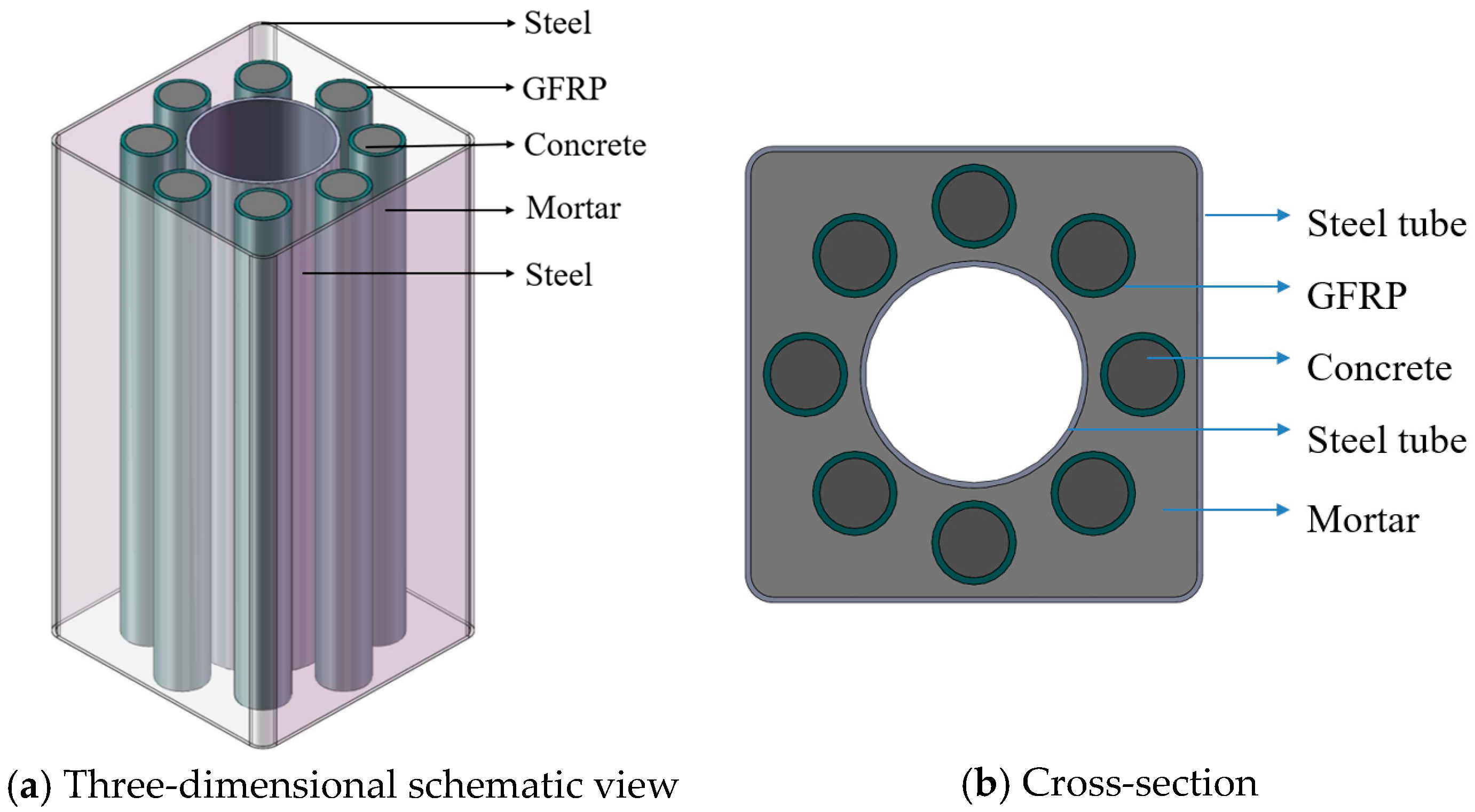
Building on these developments, this work introduces a new hybrid column type, termed square double-skin hybrid concrete bar columns (SDHCBCs), as illustrated in
Figure 2. An SDHCBC is composed of a square outer steel tube, a circular inner steel tube, and multiple SDCFs, with mortar filling the interstitial spaces. This composite configuration aims to bring together the high confinement effectiveness afforded by the outer and inner steel tubes and the superior mechanical properties of SDCFs, thereby achieving excellent load-carrying capacity, ductility, and resistance to local buckling.
Notably, compared to circular outer tubes frequently used in DSTCs or MTHCs [
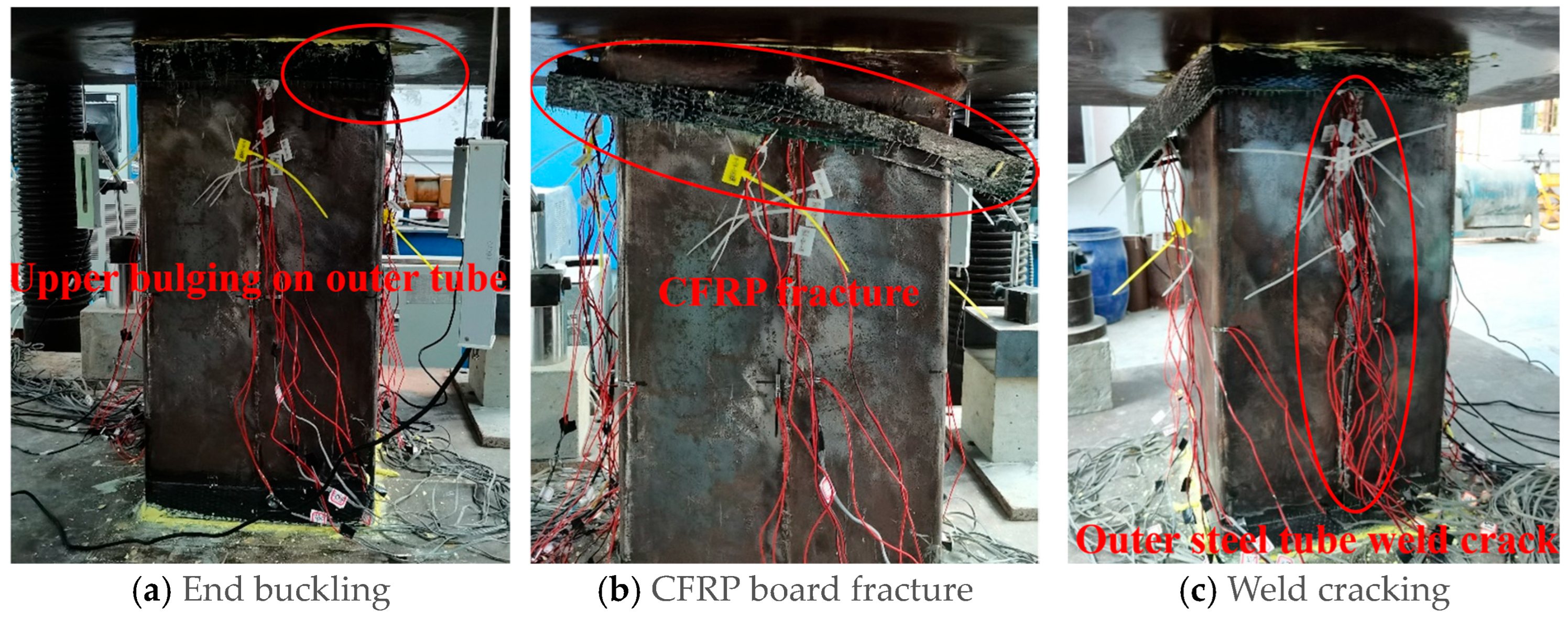
39], the square outer steel tube is purposefully adopted to facilitate beam–column joint connections and improve construction convenience. However, in square sections, lateral confinement is inherently non-uniform: it is highest at the closed corners and lowest at the midpoints of flat sides. Under axial compression, this non-uniformity fosters earlier local softening and bulging along flats. This mechanism may result in a different failure mode of the column compared with the circular outer tube confined column. Theoretically, the non-uniform confinement of the square outer tube may result in one or both of two effects in the mechanical behavior: (1) the non-uniform confinement is a weaker confinement compared with uniform confinement of the circular tube, and earlier failure may be observed; (2) for a similar reason, the ductility of the square tube confinement column may be better than the circular tube confinement column.
Therefore, a systematic study was conducted in this paper to resolve these questions and to validate the proposed SDHCBCs. A series of axial compression tests were carried out, focusing on key parameters such as the thicknesses of the outer steel tube and the GFRP tube and the arrangement of the SDCFs. Subsequently, a finite element (FE) model was developed and validated against the experimental data. The validated model was then used to resolve spatial stress and strain fields and to characterize how the three constituent materials interact in the proposed SDHCBCs.
2. Experimental Scheme
2.1. Design of Specimens
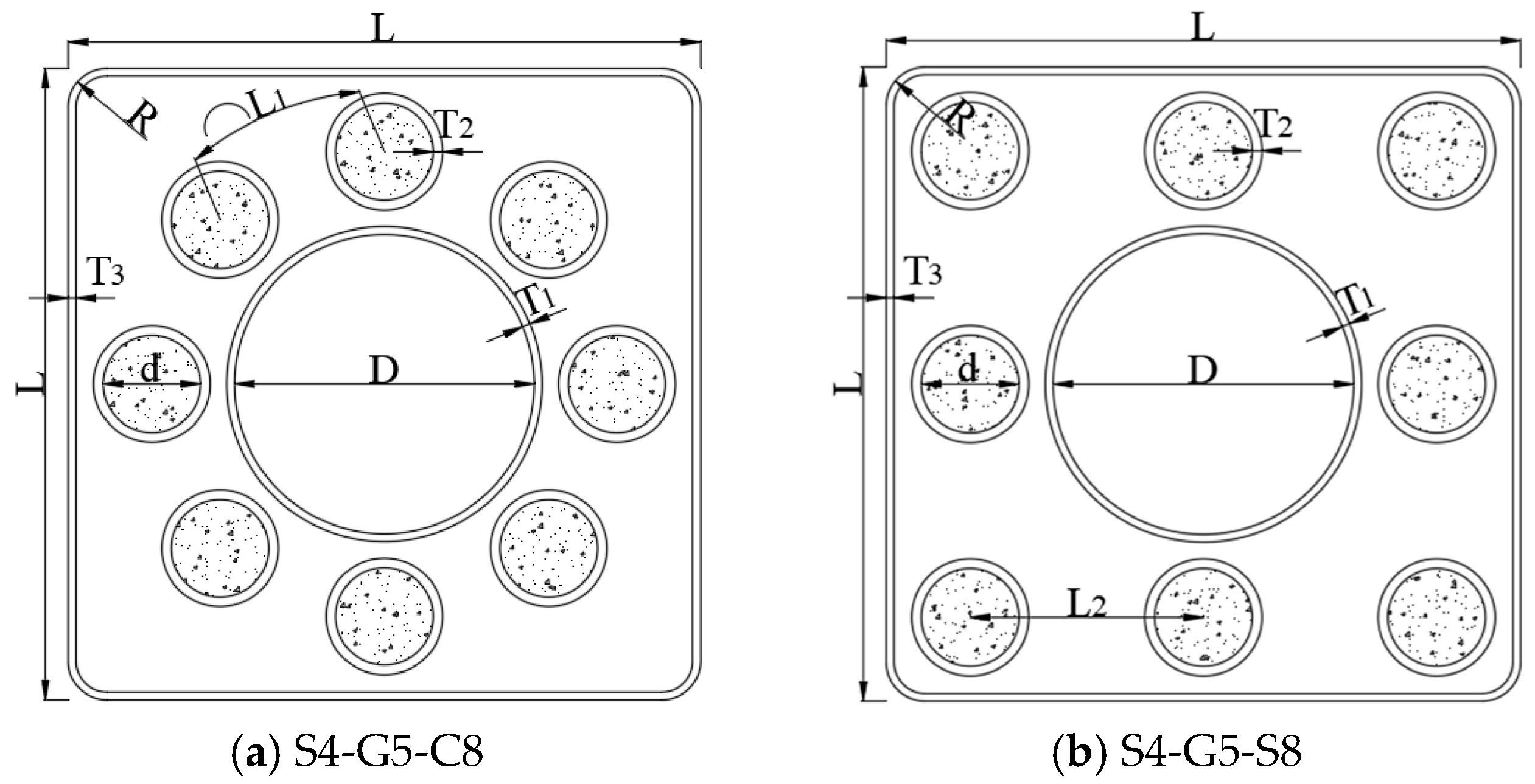
A total of nine hybrid columns were designed, comprising one specimen without SDCFs and eight SDHCBCs. The principal test variables were as follows: outer steel tube wall thickness (2, 4, and 6 mm); GFRP tube wall thickness (3.0, 5.0, and 7.0 mm); SDCF substitution ratio (0, 18.73%, 27.43%, and 38.05%); and the SDCF distribution pattern (circular or square). It should be noted that the substitution ratio is the total cross-section area of SDCFs substituted by the total cross-section area of the concrete. The default steel grade of all specimens was Q235. Detailed parameters for the specimens are presented in
Table 1 and
Table 2, and cross-sections are illustrated in
Figure 3.
The specimen labels were assigned systematically to reflect their parameters. The first number after the letter of S (e.g., 4 in S4) denotes the thickness of outer steel tube, the middle number after “G” (e.g., 5 of G5) indicates the thickness of GFRP tube, and the ending letter and number (e.g., C8) represent the distribution pattern (C for circular and S for square) and number of SDCFs. For example, “S4-G5-C8” indicates a specimen with an outer steel tube thickness of 4 mm, a GFRP tube thickness of 5 mm, and eight SDCFs distributed in a circular pattern.
2.2. Test of Material Mechanical Properties
In this study, GFRP tubes were filled with concrete, designated herein as small-diameter concrete-infilled glass FRP tubes (SDCFs). Before filling in concrete, the GFRP tubes were manufactured in the factory, where the GFRP tubes are made by multi-layer filament winding of glass fibers, with the fiber orientation alternating at ±45° to the tube axis.
In the assembling process, SDCFs were arranged in the annular space separating the inner and outer steel tubes and grouted with mortar to promote even stress transfer among all specimen components. The mix proportions of the concrete and mortar used in this study are shown in
Table 3.
The compressive strength and elastic modulus of concrete and mortar were evaluated through mechanical tests conducted in accordance with GB/T 50081-2019 [
40] and JGJ/T 70-2009 [
41], respectively. The testing procedure is depicted in
Figure 4, and the results are presented in
Table 4. The values presented in the table represent the averages of all data obtained from three separate batches of concrete and mortar casting.
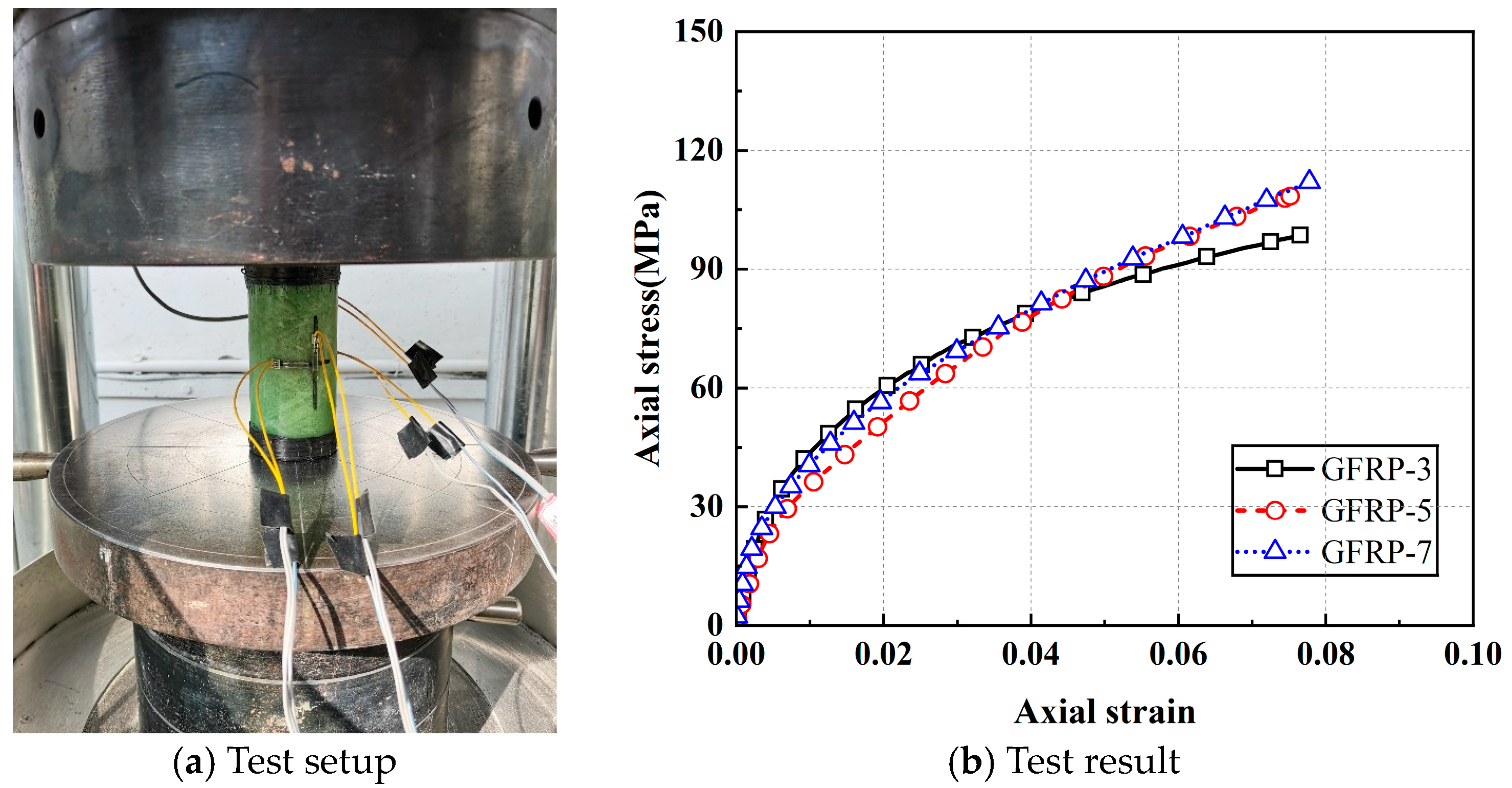
Following Reference [
36], axial compression tests were performed on concrete-filled GFRP tubes, as depicted in
Figure 5. Three specimens were prepared with a height of 120 mm and GFRP inner diameters of 50 mm, with thicknesses of 3 mm, 5 mm, and 7 mm, respectively. Prior to testing, the ends of concrete-infilled GFRP tubes were reinforced with CFRP fabric. The failure of the specimen was determined by the fracture of the GFRP tube. Test results are presented in
Table 4.
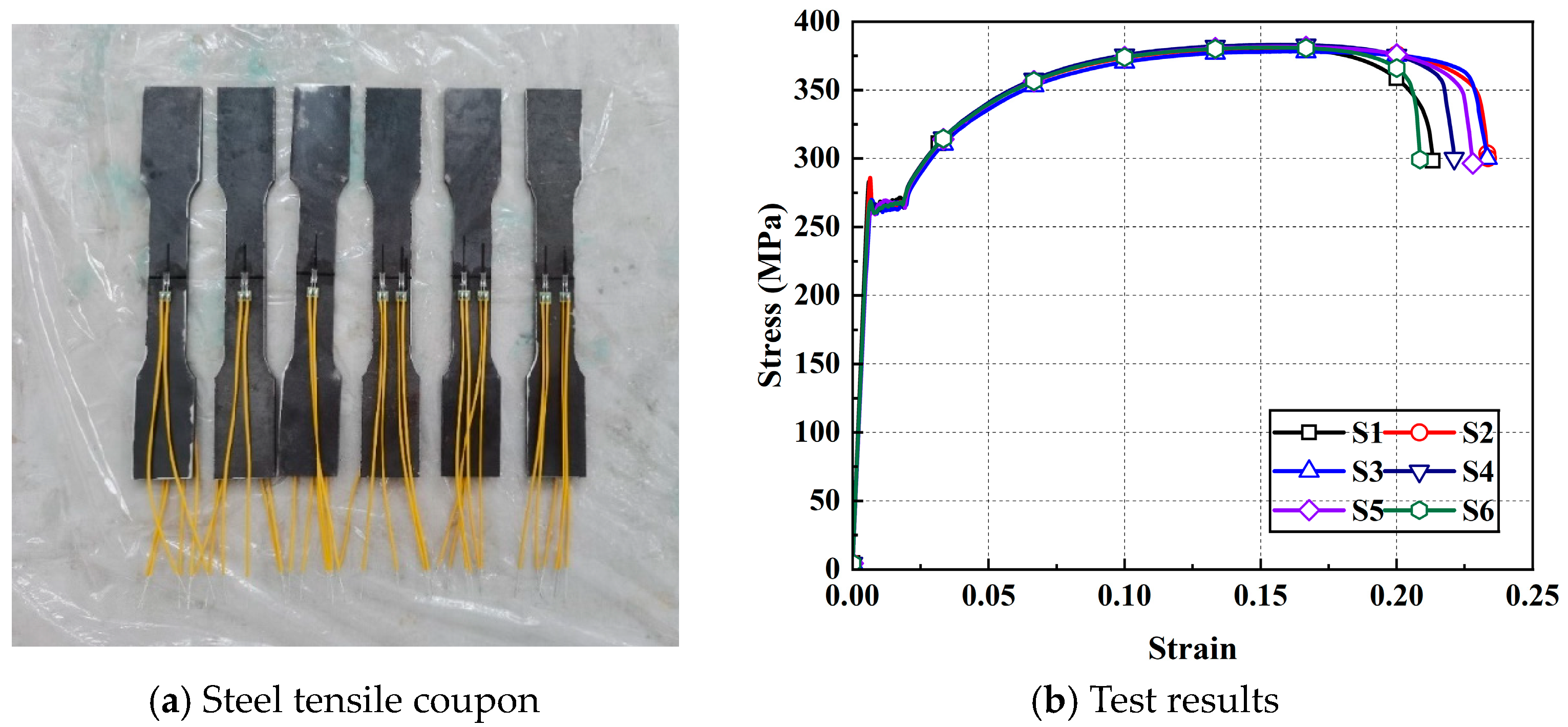
Six steel coupons sampled from different positions along the tube length were subjected to tensile testing per ASTM E8/E8M-15a [
42], and the specimens are shown in
Figure 6a. The results of the steel tensile test are presented in
Table 4 and
Figure 6b.
2.3. Specimen Preparation
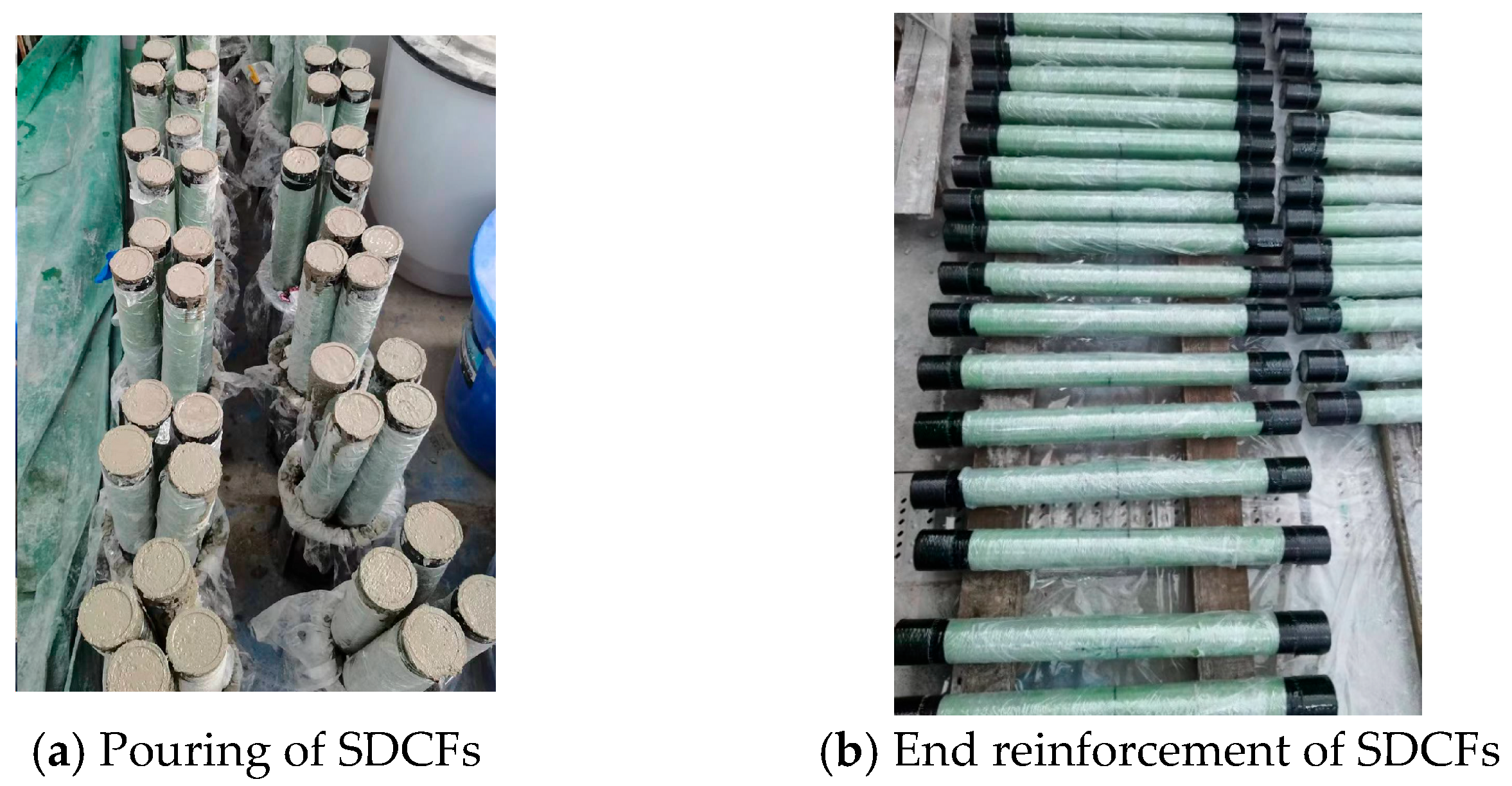
The 3D-printed molds were used to position the GFRP tubes, which were then securely fixed in place. Concrete was poured in increments, with each layer approximately one-quarter of the GFRP tube’s height. Following each pour, the mixture was vibrated on a shaking table for 30 s to guarantee complete filling of the GFRP tube and adequate compaction of the concrete. Following placement, SDCFs were cured in a standard environment for 28 days. To prevent premature failure at the ends, the upper and lower ends were wrapped with three layers of 5 mm-wide CFRP cloth. The process of fabricating SDCFs is illustrated in
Figure 7.
During the mortar pouring process, each part was initially secured using a 3D-printed template. A thick wooden board served as the base at the lower end, and glass adhesive was applied to the contact surfaces to prevent water seepage, which could potentially alter the mortar’s mix ratio. The pouring of the mortar was executed in three stages, with each layer being vibrated using a vibrating rod to guarantee adequate compaction. Following a 28-day curing period in a standard environment, the upper and lower ends of the specimen were wrapped with two layers of 5 mm-wide CFRP cloth to reduce the risk of premature failure due to stress concentration. Prior to testing, the ends of the specimen were flattened using a grinding machine.
2.4. Measuring Points and Loading Scheme
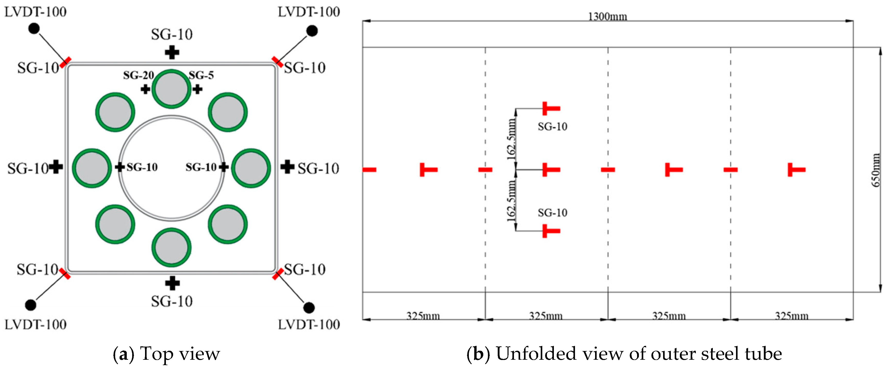
Before pouring the mortar, strain gauges of varying lengths (5 mm, 10 mm, and 20 mm) were symmetrically positioned at the mid-height of the outer surface of both the GFRP tube and the inner steel tube. To protect the gauges and ensure their waterproofing and durability, a sealant and impact-resistant paste were applied. Two mutually perpendicular strain gauges were attached at the mid-height and at distances of ±162.5 mm from the mid-height on each outer steel tube of specimens. The 10 mm-long strain gauges were positioned to measure the axial and hoop strains at the midsection, upper midsection, and lower midsection of the specimen. Additionally, one 10 mm-long hoop strain gauge was affixed at each corner to measure the circumferential strain at the corners of specimens. Furthermore, four linear variable differential transformers (LVDTs), each 100 mm in length, were positioned at the corners of the outer tube of each specimen to measure its axial displacement. The arrangement of strain gauges for specimens is shown in
Figure 8.
The axial compression test on the specimens was performed using a YAW-10000F hydraulic press (manufactured by Shiji Co., Jinan, China) with a maximum capacity of 10,000 KN. Full-section loading was applied, and the test followed a displacement-controlled loading procedure.
The loading process consisted of two steps. (1) Pre-loading: An initial load of 100 KN was applied to eliminate any potential gap between the specimen and the loading machine, ensuring proper alignment before the formal loading began. (2) Formal loading: The entire loading process was conducted under displacement control at a rate of 0.6 mm/min. Data were continuously collected using a data acquisition system, and the failure process of each specimen was recorded via video.
5. Finite Element (FE) Modeling
Numerical simulations were conducted to investigate the axial loading behavior of SDHCBCs using finite element models developed in ABAQUS. In summary, a brief list of the specifications of the FE model is first given, and the details are provided afterwards for clear demonstration.
- (1)
Element types: C3D8I for core concrete, mortar, steel tube components; SC8R for GFRP tube.
- (2)
Constitutive model: concrete damaged plasticity for concrete; secondary plastic flow model for steel; Hashin damage constitutive model for GFRP.
- (3)
Contact and boundary: Surface contact between outer steel tube, core concrete, GFRP, and inner steel tube; surface-to-surface contact with finite sliding. Both ends of the specimens: tie to rigid plates.
Details about the FE model are shown below.
The core concrete, mortar, and steel tube components were modeled using C3D8I elements (eight-node linear brick solid elements), while the GFRP tube was represented using SC8R elements (quadrilateral continuum shell elements). The meshing details for each component are presented in
Table 7.
5.1. Constitutive Model of Materials
5.1.1. Concrete
The mechanical behavior of concrete was modeled using the concrete damaged plasticity (CDP) model in ABAQUS. For the GFRP-confined core, the Jiang–Teng [
17] constitutive law for FRP-confined concrete was adopted; see Equation (2).
where
and
are the axial stress and axial strain of concrete, respectively;
is the peak strain of the unconfined concrete and
is the corresponding stress;
is the confining pressure from the FRP jacket; and
is the hoop strain of the FRP jacket.
The confining pressure increases with the hoop strain, and the relationship between axial strain and hoop strain is given by Equation (2):
where
are the elastic modulus and thickness of the FRP jacket, respectively;
is the diameter of the column.
5.1.2. Steel
Within the classical metal plasticity framework, the steel tube is modeled using the secondary plastic flow formulation [
43], expressed as follows:
where
is the proportional limit,
denotes the yield strength, and
represents the tensile strength;
is the elastic modulus; and
,
correspondingly represent the steel strain and steel stress. The basic mechanical parameters for steel are shown in
Table 8.
5.1.3. GFRP
The Hashin damage constitutive model [
44], which was firmly grounded in the theory of damage mechanics, is adopted for GFRP. Micro-damage initiates upon the application of tensile or shear loading to the material, a phenomenon explained by this theory and leading to alterations in the material’s strength and stiffness characteristics. The effects of damage within the framework of the Hashin model are contingent upon the magnitude of the damage variable. The parameters essential for the model are detailed in
Table 9.
5.1.4. Mortar
An empirical constitutive model [
45] was adopted for mortar, with Equation (5) serving as its uniaxial compressive constitutive equation.
where
a reflects the change in the deformation modulus, and
b reflects the area size of the descending segment curve. According to the references, the values of
a and
b are determined as 2.42 and 9.76, respectively. The basic mechanical parameters for mortar are shown in
Table 10.
5.2. Modeling of Bi-Material Interactions
Surface-to-surface, finite-sliding contact was used to model interactions among the outer steel tube, core concrete, the GFRP tube, and the inner steel tube. Contact behavior adopted hard contact in the normal direction with a penalty-based tangential friction law, using 0.15 as a friction coefficient. To represent weld seams, the outer steel tube—assembled from two C-shaped plates—used the same contact definitions but with the friction coefficient being 0.95. Rigid plates were attached at both ends, and tie constraints were applied to deliver uniform loading.
5.3. Boundary Conditions
The top rigid plate was constrained in all directions, with the exception of displacement loading in the z-direction. When setting the boundary conditions for the rigid plate positioned at the bottom of the specimen, it is necessary to consider two scenarios separately: the scenario with an intact outer steel tube and the scenario with a cracked weld seam. For the scenario where the outer steel tube is intact, the boundary condition was fully fixed. However, in the case of a cracked weld seam, the restraining effect of the outer steel tube undergoes a drastic diminution, which subsequently induces compressive member instability within the core concrete and ultimately results in eccentric loading of the specimen. In such circumstances, the boundary condition was designated as hinged, implying that while displacement freedom was constrained, rotational freedom remained unconstrained. The timing of these two conditions was determined through experimental observations, wherein the hybrid column fails as a result of the loss of restraining capability of the outer steel tube due to weld seam cracking, manifesting as a descending phase in the load–displacement curve.
5.4. Results and Discussions
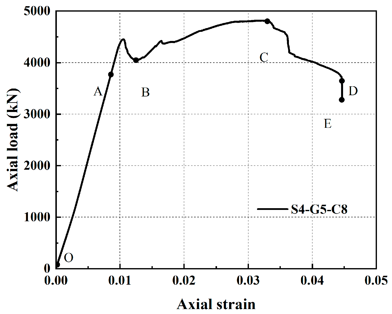
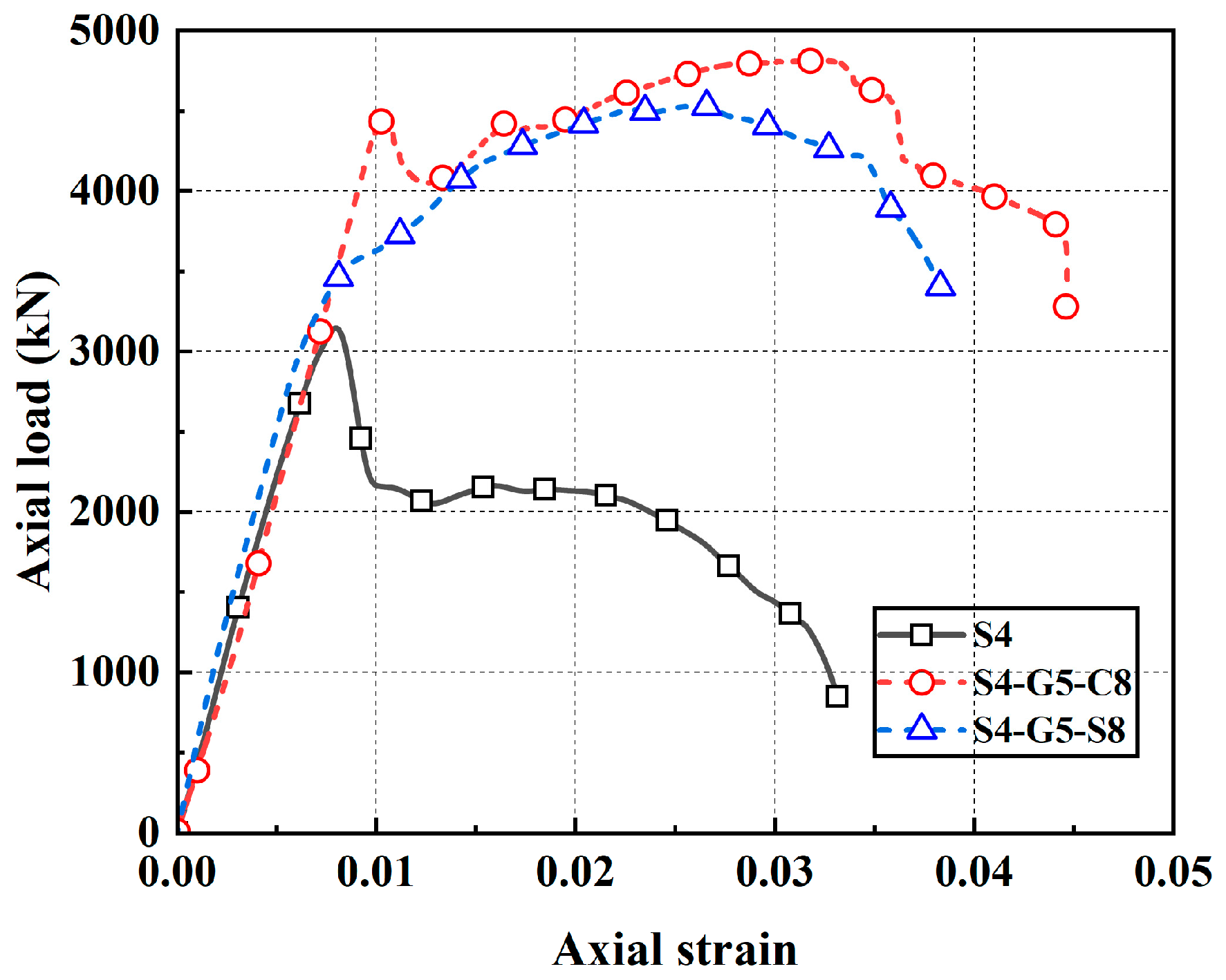
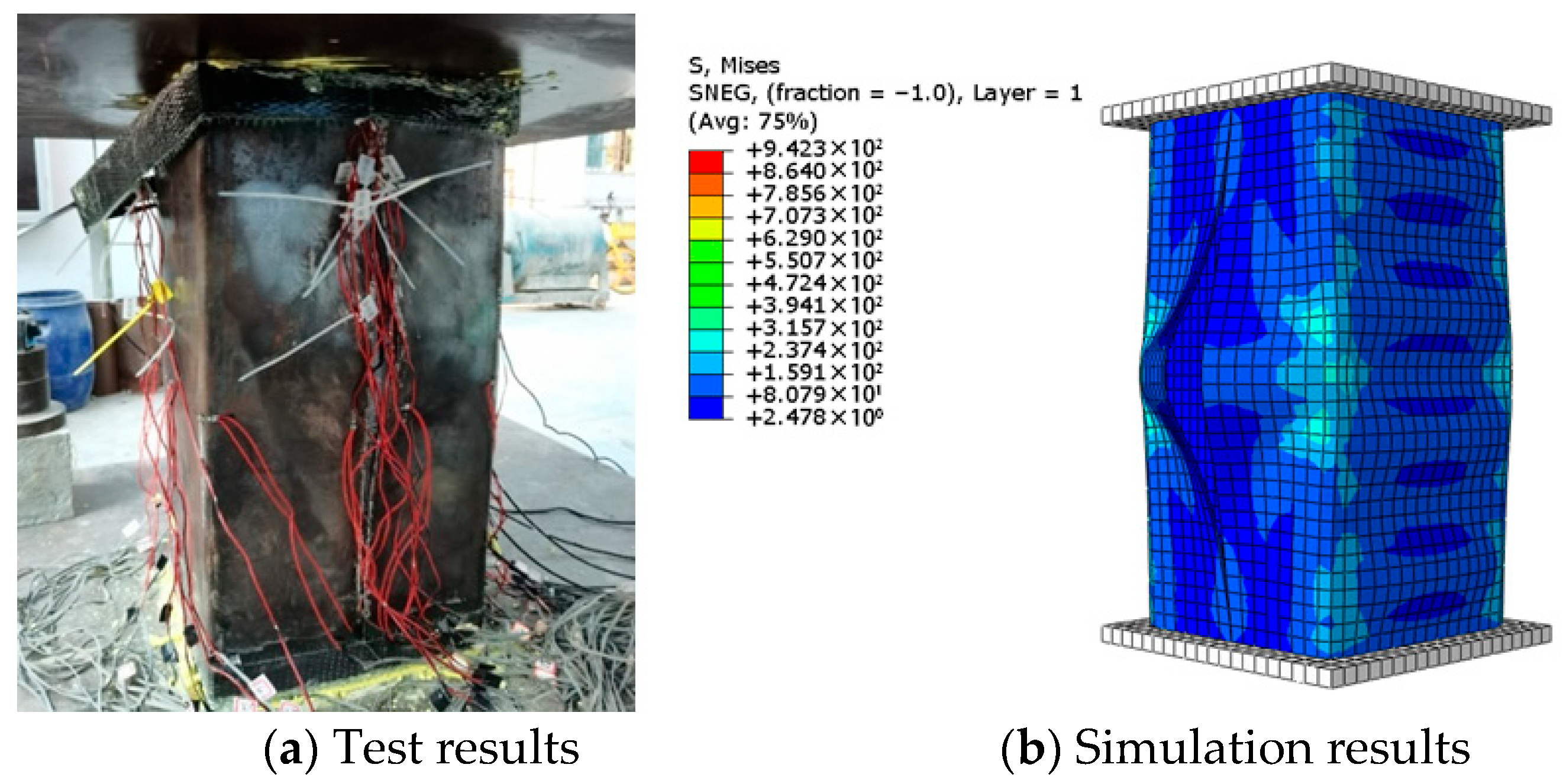
Figure 23 and
Figure 24 present a comparison between FE predictions and the measured response of specimen S4-G5-C8 across the hardening and post-peak softening phases. During the hardening stage, slight welding cracks and bulging deformation of the outer steel tube were observed. During the descending stage, the ultimate bearing capacity of the specimen was reduced to below 70% of its initial value, signifying the failure of the hybrid column. At this stage, the outer steel tube exhibited complete welding cracks, along with obvious bulging deformation, and a stress concentration phenomenon was observed at the corner of steel tube. The specimen exhibited biased compression toward the weld crack, and the results of the finite element simulation were in good agreement with the experimental results.
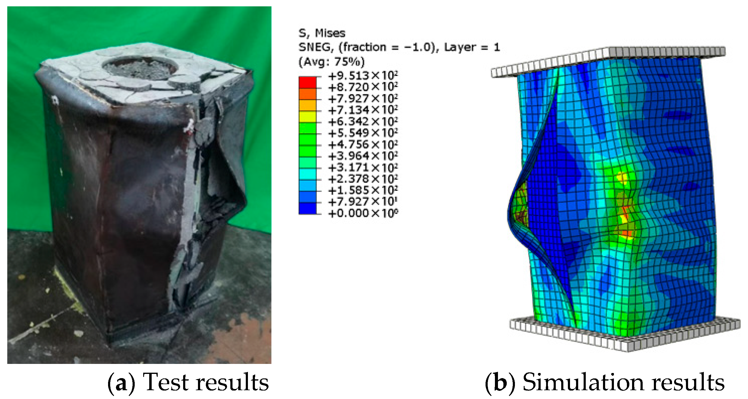
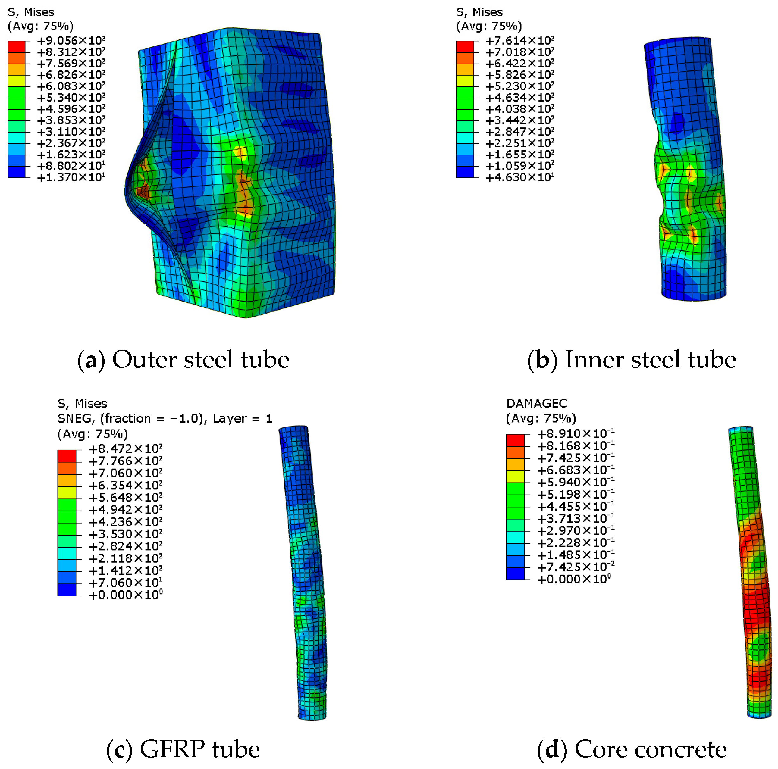
The finite element simulation results for each component, obtained when the reaction force of S4-G5-C8 was reduced to 75% of their peak values, are presented in
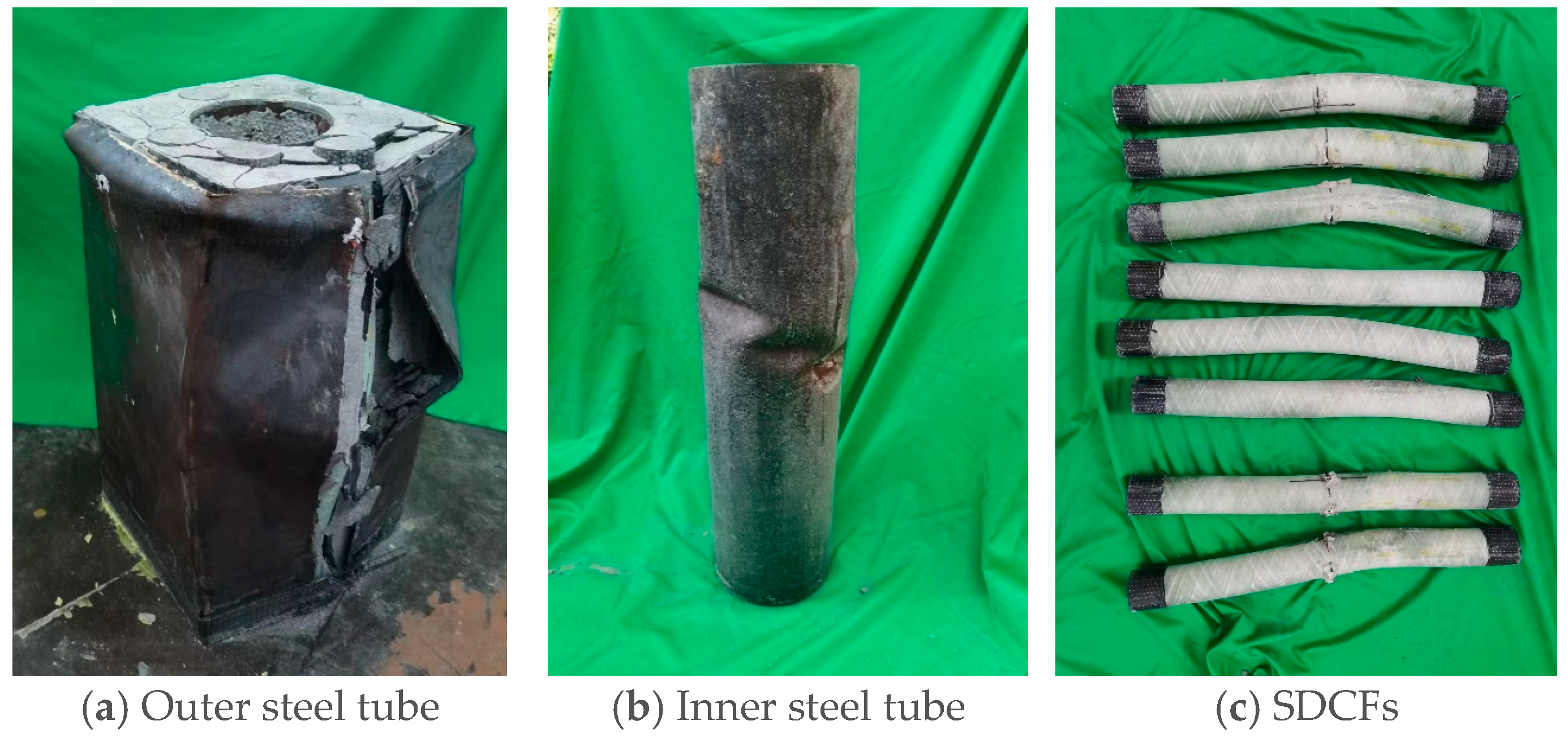
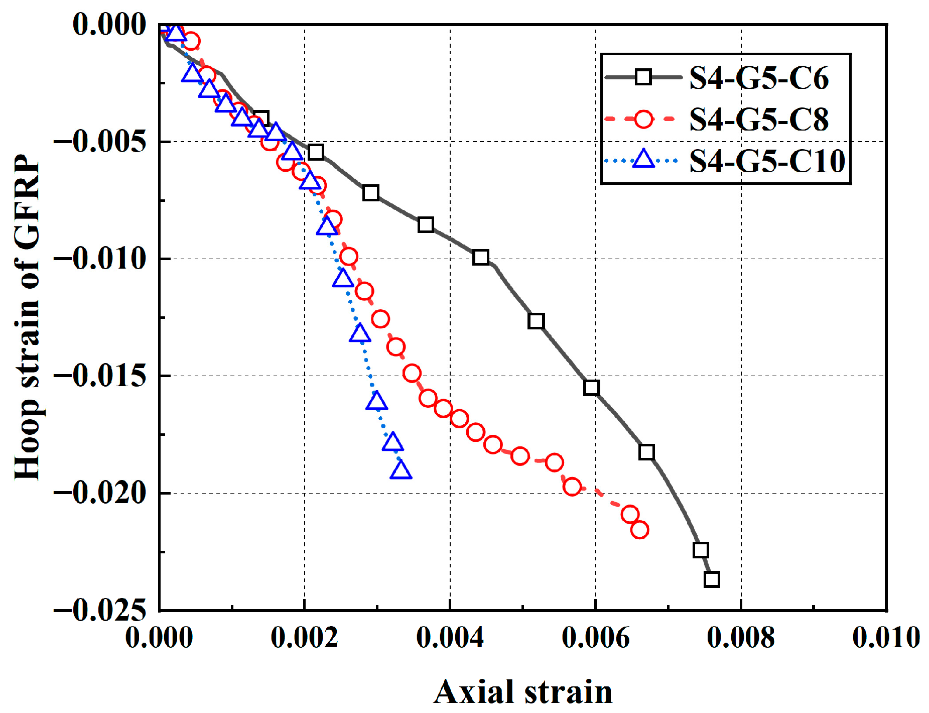
Figure 25. Significant buckling was observed in both inner and outer steel tubes, accompanied by complete weld tearing and mortar crushing, which resulted in the loss of its restraining ability on SDCFs. The large slenderness ratio of SDCFs leads to instability of the compression bar under pressure, thereby causing the phenomenon of eccentric compression. The compressive damage to the middle and lower sections of core concrete was the most significant at this point, with a value of 0.891, accompanied by notable bending deformation. At the corresponding location within the GFRP tube, a notable bending phenomenon was also observed, accompanied by the highest stress levels. The specimen was deemed to have lost its load-bearing capacity.
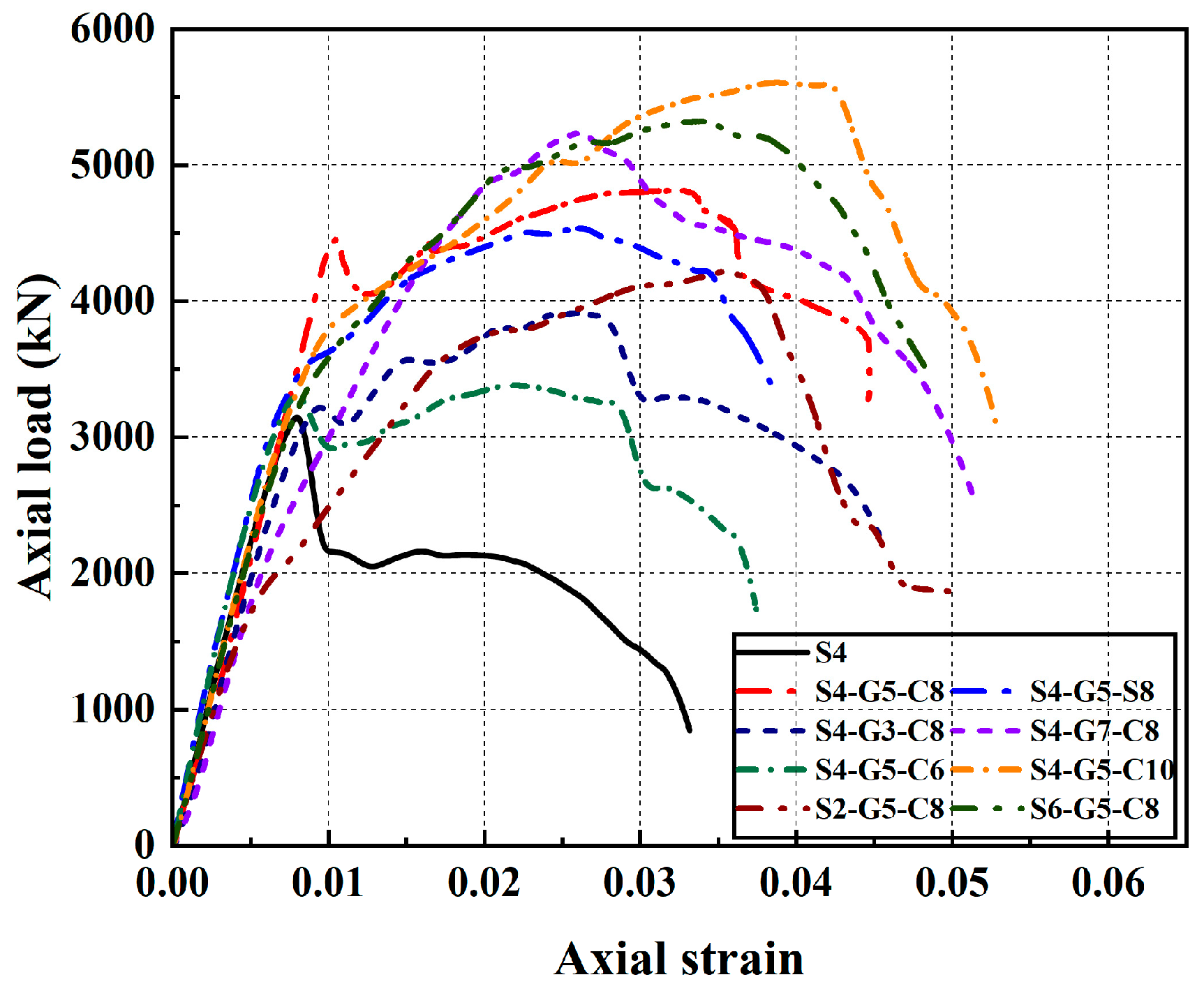
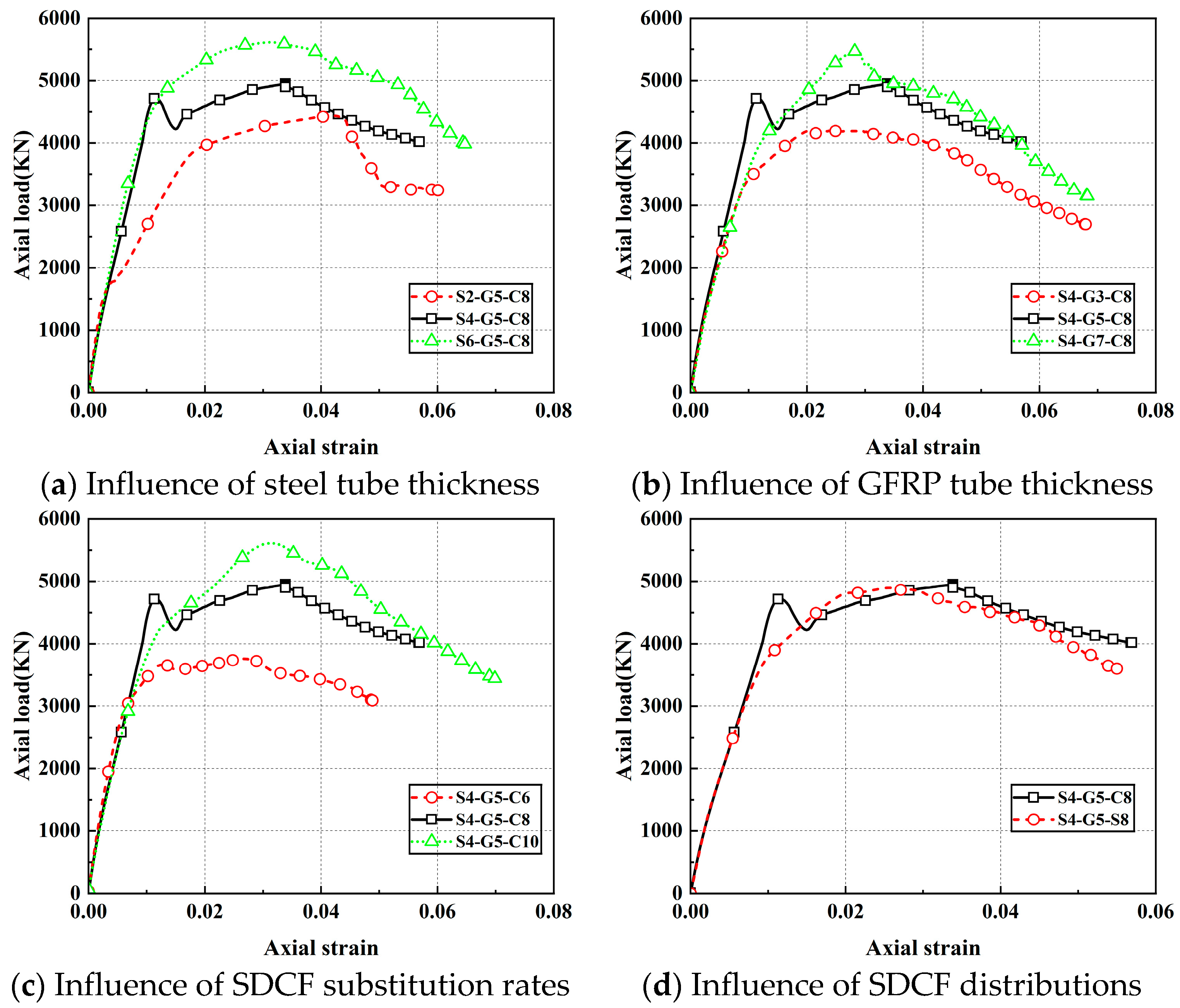
Figure 26 presents FE-simulated axial load–axial strain responses for cases with varied outer steel wall thickness, GFRP wall thickness, SDCF substitution ratio, and SDCF distribution pattern. Making the outer steel and GFRP tubes thicker, and adopting a higher substitution ratio, markedly enhances the ultimate bearing capacity and ductility of the hybrid columns. Increasing the thickness of both the outer steel tube and GFRP tube enhances the confinement on the core concrete, thereby improving the bearing capacity of the specimen. When the outer steel tube is thin, it fails to provide effective confinement to the internal components under axial load. This inadequacy leads to premature buckling and consequently shortens the elastic stage. Since the SDCF serves as the primary load-bearing component, a thicker GFRP tube enhances the bearing capacity of the SDCFs but also increases its brittleness, leading to a more pronounced post-peak decline in the hybrid column. An increase in the substitution rate results in a higher load capacity of the specimen in the strengthened section. A square GFRP tube more effectively bears the load at the specimen’s corners, ensuring a steady increase in bearing capacity and preventing a steep load drop.
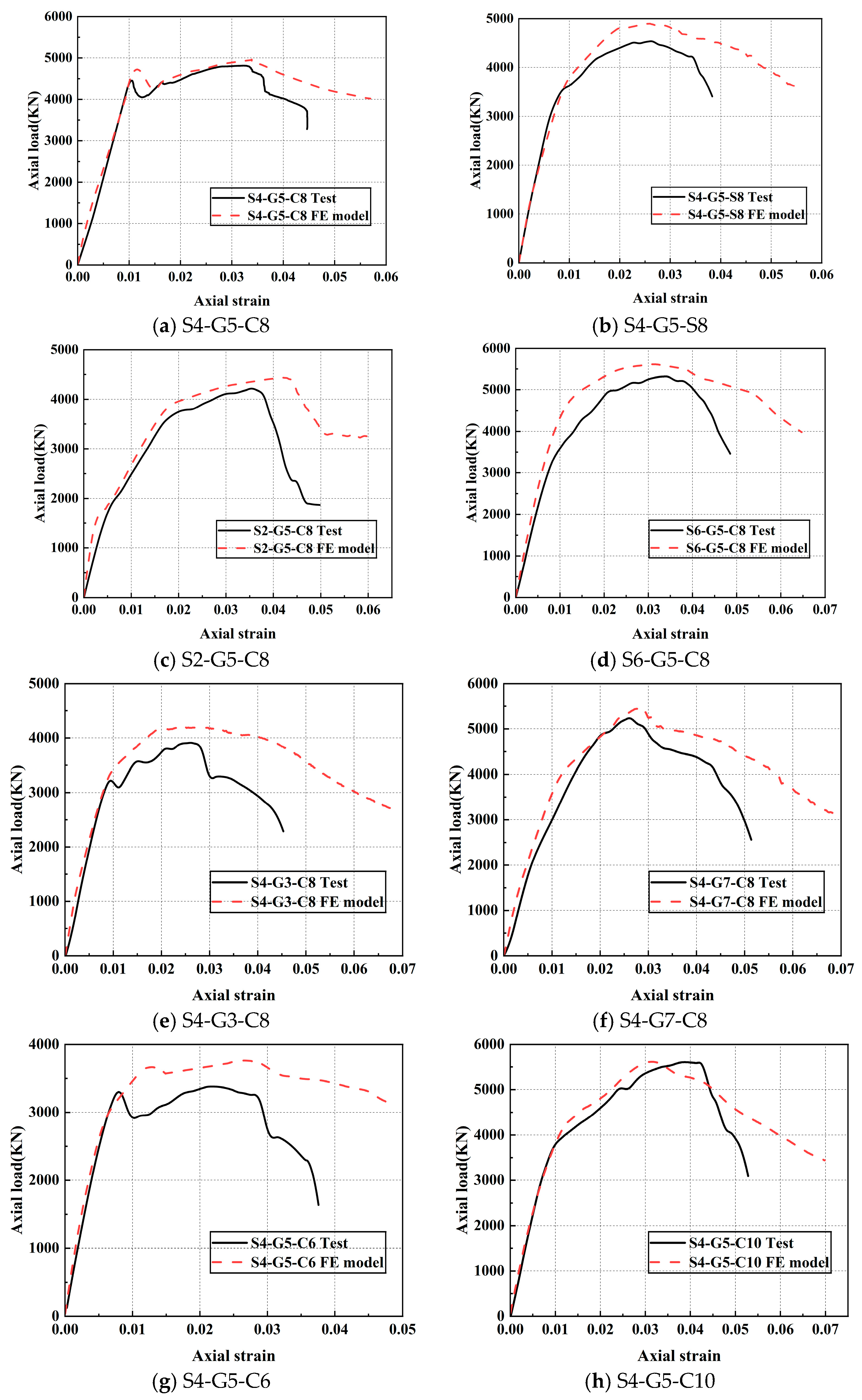
Figure 27 juxtaposes, for each specimen, the axial load–axial strain curves from experiments and FE analysis.
Table 11 compiles the ultimate capacities reported by the tests and the simulations. The numerical simulation curves closely match the experimental curves, with peak load discrepancies remaining within 10%.
The ultimate load-bearing capacity predicted by the numerical simulations exceeds that observed in the experimental curves, and the descending stage of the numerical simulation curves shows a slower rate of decline compared to the experimental results. This phenomenon was attributed to multiple factors, including the following: (1) the sedimentation and uneven distribution of aggregates in the mortar, which hindered it from achieving its optimal restraining capacity; (2) the influence of simplification of bonding condition between components; and (3) eccentricity of experimental specimens. In contrast, the numerical simulations fully accounted for the mortar’s restraining capacity. In the experiments, the hybrid column was deemed to have reached ultimate failure when the welds in the outer steel tube fully cracked, even though SDCFs had not yet completely failed. In the numerical simulations, the model was considered to have reached ultimate failure when the concrete damage exceeded 0.891, indicating the complete failure of the SDCFs. This also confirms that the SDCFs were the primary load-bearing component of the hybrid column.

