Abstract
During the construction of deep underground soft rock strata, the adverse effects of high geostress, unfavorable geological conditions, and excavation disturbances are significant, easily triggering Material-Stress-Induced (MSI) large deformation disasters, leading to the failure of support structures or even collapse, thus posing great challenges to the safe construction of this type of underground engineering. Based on this, this study first classifies the large deformations, analyzes the instability mechanism of material-stress-induced large deformation in soft rock, and identifies the influencing factors of this type of large deformation from three aspects. Subsequently, a numerical investigation (FLAC3D 6.00) is utilized to examine the surrounding rock deformation characteristics under different material factors (uniaxial compressive strength and elastic modulus), stress factors (burial depth and lateral pressure coefficient), and construction factors (excavation method, support pattern, and timing of initial support installation). On this basis, a multi-factor sensitivity comparison analysis is conducted, which clarifies the differences and prioritization of parameter influences on large deformation, and reveals the dominant role of controlling factors such as elastic modulus. The analysis demonstrates a strong negative correlation between the examined material factors (uniaxial compressive strength and elastic modulus) and the magnitude of surrounding rock displacement, with both values eventually converging. A significant positive correlation between the examined stress factors and the magnitude of surrounding rock displacement was observed. A pronounced positive correlation was observed between stress factors and surrounding rock deformation. These factors distinctly have different effects on the peak displacement of different surrounding rock parts. Vault settlement demonstrates the most pronounced displacement, while arch bottom deformation is the least apparent. The three excavation methods exhibit relatively low sensitivity to surrounding rock displacement. Similarly, the support patterns demonstrate limited influence on surrounding rock deformation. The material factor of soft surrounding rock is the main controlling factor of the large deformation of soft surrounding rock in deep underground engineering. The elastic modulus has the strongest influence on the displacement of the surrounding rock. When the elastic modulus is less than 2 GPa, the sensitivity coefficient is much higher than the stress factors. The research results can provide some reference and guidance for similar underground projects.
1. Introduction
As China’s economy continues to grow robustly and the “Belt and Road” initiative advances steadily, the scale of tunnel and underground engineering construction has been expanding year by year. Concurrently, national infrastructure development is now prioritized in central and western regions, areas characterized by increasingly complex topographic, geological, and geomorphological conditions [1]. Among them, deep underground engineering crossing soft rock strata with great burial depth continues to emerge (see Figure 1a). Due to the poor stability of soft rock itself, coupled with the environment of high geostress, high ground temperature, and high-permeability water pressure (“three highs”) in deep underground engineering, large-scale excavation disturbances can easily trigger surrounding rock instability and failure, leading to a series of serious engineering accidents such as cross-section reduction, lining cracking, and even large-scale collapse [2,3,4] (see Figure 1b). During the construction of the Lianchengshan Tunnel of the Baoji–Hankou Expressway, serious squeezing and large deformation disasters occurred due to chlorite schist, which were manifested in the distortion and fracture of the steel frame, cracking and falling of shotcrete and inverted arch bottom heave, resulting in serious lag of project progress and huge losses [5]. The surrounding rock of the Haba Snow Mountain Tunnel on the Dian–Tibet Railway mainly consists of fragmented and foliated basalt interbedded with tuff. During construction, extremely severe large deformation problems also occurred, causing serious damage to the support structures. In particular, the secondary lining was entirely crushed over a length of 189 m, resulting in significant construction delays and seriously affecting tunnel construction safety [6]. Therefore, investigating the key factors and sensitivity governing large deformations in soft surrounding rock is essential to enhance safety, mitigate potential risks, and optimize cost efficiency in deep underground engineering projects.
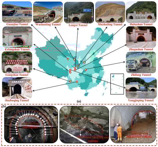
Figure 1.
Underground engineering of soft rock surrounding rock in China and large deformation disaster: (a) Underground engineering of deeply buried soft surrounding rock; (b) Form of large deformation disaster.
To address the influence factors and sensitivity analysis of large deformation disasters in surrounding rock in deep underground engineering, scholars have conducted extensive research and engineering practice, mainly using field measurement data methods and numerical analysis methods. The field-measured data method uses prearranged monitoring points to obtain data on displacement and stress for sensitivity analysis [7,8,9]. However, this approach requires substantial human, material, and financial resources for the preliminary installation of monitoring points. At the same time, the monitoring results obtained are difficult to compare and analyze between different working conditions, so it is difficult to realize the sensitivity analysis of influencing factors. In contrast, the numerical simulation analysis method mainly relies on numerical calculation software, through parametric efficient modeling and construction of a variety of working conditions for simulation, and then obtains more abundant and stable data, such as displacement and stress at different monitoring points, so as to make it easier to compare the monitoring data under different working conditions for sensitivity analysis.
Yang et al. [10] constructed a numerical model of a red-bed soft rock tunnel using the numerical simulation method and revealed the influence of key factors, such as expansion force, inverted arch stiffness, and in-situ stress, on the uplift deformation of the inverted arch in the red-bed tunnel. It is concluded that the uplift of the inverted arch is most sensitive to the expansion force. Zhu et al. [11] employed the finite difference method to perform a sensitivity analysis on the factors influencing tunnel face extrusion deformation. Findings demonstrate that tunnel face stability is predominantly governed by two factors: excavation height of the upper step and the surrounding rock classification. Li et al. [12] examined the influence of parameters on tunnel surrounding rock deformation using numerical simulation, and carried out sensitivity analysis, revealing that the main parameters affecting the displacement of tunnel surrounding rock are the internal friction angle.
Zhao et al. [13] showed that cohesion and internal friction angle had the greatest influence on tunnel vault settlement by combining the numerical simulation method (ABAQUS) and grey correlation theory. Yang et al. [14] studied the influence of rock mass parameters on the stability of tunnel surrounding rock by the numerical test method. Cohesion was identified as a key determinant of plastic zone extent, in contrast to material density, which was found to have a marginal impact. Sun et al. [15] established numerical tunnel models at different weathering degrees using finite-difference numerical simulation software. The results indicate that highly weathered argillaceous sandstone exhibits the highest sensitivity to surrounding rock deformation and structural stress, while weakly weathered argillaceous sandstone shows the lowest sensitivity.
Furthermore, weakly weathered argillaceous sandstone demonstrates greater sensitivity to the internal friction angle than to cohesion. Deng [16] analyzed the sensitivity of surrounding rock parameters by establishing a numerical model of an underground hydropower station and obtained that the elastic modulus is a highly sensitive parameter, and the Poisson’s ratio is a low-sensitivity parameter. Liu et al. [17] used FLAC3D to investigate the influence of different weak interlayer parameters on the deformation characteristics and failure modes of tunnel-type anchorages. The analysis reveals that the inclination of the weak interlayer governs deformation response, serving as the dominant control on stability.
Chen et al. [18] analyzed the impact of various mechanical parameters on the displacement of underground caverns by the numerical test method, and concluded that the sensitivity of elastic modulus is always the largest for both vault settlement and horizontal convergence of the side wall. Zhang et al. [19] took the Xiluodu Hydropower Station on the Jinsha River as a case study. Through numerical simulations, they revealed that reservoir impoundment and water immersion exacerbated the toppling deformation of the underlying soft rock mass in the slope, and further analyzed its toppling stability. Using acoustic emission (AE) nondestructive testing technology and a uniaxial compression experimental system, Zhang et al. [20] discovered that precursor AE time series follow the time-reversed Omori’s law. By applying this law, they accurately predicted catastrophic failure based on the trend of the RT rate as the time series approached rupture. Wang et al. [21] revealed the effect of construction factors on the stability of surrounding rock by numerical simulation. The results show that with the increase of tunnel depth, the dominant factor affecting the deformation of surrounding rock changes from tunnel depth to the mechanical properties of the rock itself. Liu et al. [22] investigated how the mechanical parameters of bolt/cable and surrounding rock affect anchorage force. Their results identified the bolt/cable diameter and elastic modulus as the primary influencing factors. Zhou et al. [23] studied the mechanical behavior of fractured rock mass samples under different influencing factors using a numerical simulation method and analyzed the sensitivity of these factors, determining that rock mass mechanical properties were the primary influence.
The above research has significantly advanced the study of influencing factors and sensitivity of large deformation in deep underground engineering, providing important theoretical support for safe construction. However, systematic analysis under the specific geological conditions of soft surrounding rock remains insufficient, particularly regarding the instability mechanism of material-stress-induced large deformation. Most existing studies focus on single or limited parameters, without fully comparing the relative impacts of multiple factors. In this context, this study systematically compares material, stress, and construction factors, clarifies their influence on large deformation, and provides a sensitivity ranking that highlights the dominant role of elastic modulus.
Compared with previous works, the primary contribution of this study is its comprehensive multi-factor comparison and explicit identification of parameter priorities, thereby addressing the lack of multiple-factor analysis and offering more targeted strategies for mitigating and managing soft rock large deformation disasters.
In view of this, this study first classifies the large deformations of soft surrounding rock in underground engineering, taking the particularly frequent material-stress-induced large deformation in deep underground engineering as the research object to analyze its instability mechanism and failure patterns, and, based on extensive literature statistical analysis, identifies the influencing factors of material-stress-induced large deformation from three aspects: material, stress, and construction. Then, a numerical investigation (FLAC3D) is utilized to design the numerical simulation test, and the response law of different material factors, different stress factors and different construction factors to the displacement field of the surrounding rock in deep underground engineering is systematically studied. Finally, using sensitivity analysis, the influencing factors in MSI large-deformation stability engineering are analyzed to assess each factor’s sensitivity to large deformation and provide a corresponding ranking. These findings provide valuable guidance and reference for preventing large-deformation disasters induced by MSI in deep soft rock engineering.
2. MSI Large Deformation of Soft Rock in Deep Underground Engineering
2.1. Classification of Soft Rock Large Deformation in Deep Underground Engineering
Constructing underground engineering in deep underground environments, especially in high-geostress soft surrounding rock strata where the surrounding rock minerals are of low-expansion type, is prone to disasters such as large deformation, long deformation duration, and slow deformation convergence of the surrounding rock. Therefore, it is necessary to classify the types and causes of large deformation in soft surrounding rock in deep underground engineering in order to accurately understand their mechanisms of action. Based on previous research results [24], this study classifies the large deformations of surrounding rock in underground engineering according to their causes into the following three categories: (1) those caused by excavation in special rock types (low-strength surrounding rock, expansive surrounding rock), which can be further subdivided into material-stress-induced and material-chemical-induced types; (2) those caused by shear failure of the rock mass under high stress; and (3) those caused by instability of rock mass structural planes induced by excavation. Among them, the large deformation of surrounding rock with low material strength under the action of high ground stress and no obvious volume expansion belongs to the material-stress-induced large deformation, which is mainly manifested by the ductile flow deformation of soft rock [25]; in the case of water, the strength of the material is reduced or the volume expansion is caused, which belongs to the material-chemical large deformation in the material type. Under the action of high stress, the shear failure of the surrounding rock with a certain strength occurs, and the resulting large deformation belongs to stress-induced large deformation [26].
The large deformation caused by the instability of the structural plane is a large structural deformation, which mainly includes the slip along the structural plane, the slip formed by the unstable wedge formed by the structural plane, etc. [27]. Among the types of large deformation mentioned above, material-stress-induced large deformation disasters are particularly frequent and hazardous in deep underground soft rock engineering, making them the most prominent type among all large deformations. Therefore, it is urgently necessary to conduct relevant research on material-stress-induced large deformation disasters in deep underground soft rock engineering.
2.2. MSI Large Deformation Mechanism and Influencing Factors of Soft Rock in Deep Underground Engineering
Soft rock material-stress-induced large deformation in deep underground engineering can be considered as a deformation and instability failure phenomenon with significant time-varying effect under the dual effects of low rock material strength and high ground stress. According to the mechanical mechanism of large deformation, the instability mechanism of large deformation can be considered as plastic flow and shear slip of soft rock [28]. Soft rock under high geostress exhibits significant rheological properties, resulting in a progressively developing plastic zone in underground engineering structures, as illustrated in Figure 2a. In this process, the rheological effect makes the elastoplastic stress state of the surrounding rock undergo a long-time adjustment, resulting in a continuous expansion of the damage range.
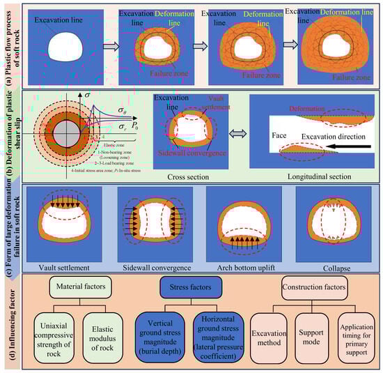
Figure 2.
Instability mechanism of material-stress large deformation and influence factors.
At the same time, the surrounding rock is often accompanied by inward extrusion deformation after the expansion deformation, resulting in the deformation of soft rock in underground engineering for a long time. The plastic shear slip deformation mode is the main instability mode of large deformation in soft rock underground engineering. Figure 2b illustrates the redistributed stress state in the elasto-plastic surrounding rock of a deep circular tunnel. Zones 2 and 3 are collectively referred to as the bearing area, characterized by a post-excavation tangential stress that is higher than the initial in-situ stress. Conversely, Zone 1 constitutes the non-bearing area, as the tangential stress near the tunnel contour here falls below the pre-excavation stress level. Within the loose zone, decreased confining stress causes a deterioration in rock mass strength. This induces a loosened structure and the widening of existing fractures. The rock mass in this range should be supported in time after excavation to avoid significant plastic slip. Shotcrete should be applied immediately to seal the rock surface, simultaneously with the installation of high pre-stressed anchor bolts and grouting for reinforcement.
Plastic deformation in the surrounding rock induces the formation of shear slip surfaces. In intact rock, these surfaces are governed by the trajectory of principal stresses, whereas in fractured rock masses, they develop along pre-existing structural planes. The result is to further cause the expansion of the surrounding rock and lead to further fragmentation of the rock mass. At the same time, due to the softening effect of groundwater seepage along the fracture, the strength of the surrounding rock mass will be further reduced and its plastic flow will be promoted, thus increasing the deformation of the surrounding rock [29]. The main performance is that the vault sinks and the two sides converge and bulge (see Figure 2b). This kind of large deformation often takes a very long time to reach stability (see Figure 2c).
To accurately analyze the material-stress-induced large deformation and ensure the stability of the surrounding rock, it is essential to scientifically and rationally determine the influencing factors of the stability of soft rock in deep underground engineering. Based on extensive literature statistics of large deformation cases in soft rock of deep underground engineering, this paper extracts the influencing factors of large deformation stability in typical projects. Following the principle of importance and the principle of independence, factors such as data collection (e.g., meteorological surveys) and on-site management (e.g., construction organization design) were excluded. Simultaneously, closely related influencing factors were categorized and consolidated. Ultimately, the influencing factors can be summarized as material factors, stress factors, and construction factors that consider construction conditions and support conditions (see Figure 2d). The material factors are divided into uniaxial compressive strength and elastic modulus of the surrounding rock. The stress factors are divided into vertical ground stress (buried depth) and horizontal ground stress (lateral pressure coefficient). The construction factors are divided into excavation method, support mode, and initial support construction time.
3. Three-Dimensional Numerical Model Construction and Experimental Design
3.1. Numerical Model Experimental Scheme
In this study, the finite difference method (FLAC3D) was adopted for numerical modeling. This method is particularly suitable for simulating large strains, nonlinear elastoplastic behavior, and progressive failure, making it well-suited for analyzing plastic flow and large deformation of soft rock under high in-situ stress conditions. In comparison, the finite element method (FEM) has limitations in handling large deformation and nonlinear contact, while the discrete element method (DEM) is more appropriate for discontinuous media rather than the continuous rock mass considered in this work. Although coupled fluid–solid approaches can capture more complex multi-physical interactions, their model construction is highly complicated and does not align with the aim of our study, to analyze the rock mass response and perform sensitivity analysis of influence factors. Therefore, FLAC3D provides direct capabilities for modeling stepwise excavation and support elements (e.g., bolts and shotcrete), enabling effective simulation of construction processes and rock mass responses [30], and FLAC3D offers distinctive advantages over other numerical methods in addressing large deformation problems of soft rock.
To investigate the characteristics of the deformation law of surrounding rock in deep underground engineering under different influencing factors, the influencing factors of material-stress-induced large deformation and the standard values of physical and mechanical indexes of surrounding rock at all levels are comprehensively determined. A controlled-variable approach was employed to investigate how individual factors affect the deformation of the surrounding rock following cavern excavation. Table 1 presents the symbols and abbreviations of the influencing factors, and the numerical simulation test scheme is designed as shown in Table 2 (A (Shotcrete layer), B (Shotcrete layer and Anchor cable(bolt), C (Shotcrete layer and Steel frame), D (Shotcrete layer, Anchor cable(bolt) and Steel frame)). Among them, the influence of support is not considered for the material factors and stress factors. The variation patterns of surrounding rock displacement are studied solely by varying the corresponding parameters during underground excavation. By examining the vault settlement displacement, arch bottom uplift displacement, haunch convergence displacement, and displacement variations with excavation steps under changing conditions of different factors, this study analyzes the sensitivity of various influencing factors on material-stress-induced large deformations in soft rock within deep underground engineering.

Table 1.
Symbol and Abbreviation Table.
Table 2.
Numerical experimental design.
3.2. Numerical Model Construction
The cross-section of the carve is characterized by a vertical wall arch and a minor bottom arch. The width is 6.0 m, and the height is 5.3 m. The vault is a circular arc with a radius of 3.0 m and a vector height of 1.9 m. The height of the section straight wall is 2.3 m, and the height of the bottom arch is 1.1 m. The specific size of the numerical model for the underground engineering is illustrated in Figure 3. A vertical load is exerted on the model’s top boundary to simulate the overburden stress, whereas displacement constraints are employed on the lateral and bottom boundaries. Assuming an excavation depth of 1200 m for the underground engineering, the overlying strata (γ = 25 kN/m3) are converted into a geostress of σ1 = 30 MPa and applied on the upper surface of the computational model (z = 25 m). A stress boundary condition was prescribed at the model’s top surface, while its bottom (z = −25 m) was treated as fully fixed in all degrees of freedom. and displacement constraints are applied on the left and right (x = ±25 m) and front and back (y = 0, y = 10 m) boundaries of the model. Meanwhile, horizontal geostresses σ2 = σ3 = 45 MPa are applied. Considering computational efficiency, except for different excavation methods, the right half of the model is used for analysis based on model symmetry.
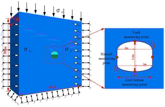
Figure 3.
Three-dimensional numerical model and size.
3.3. Mechanical Parameters of the Numerical Model
In the process of numerical calculation, the surrounding rock of underground engineering is regarded as an isotropic Mohr–Coulomb ideal elastic-plastic material. The support structure constitutive model applies an Elastic model to simulate the shotcrete, which is modeled by adjusting the physical and mechanical parameters of the solid elements. Beam elements are used to simulate the steel arches, while cable elements are used to simulate the anchor bolts and anchor cables [30]. In this paper, a set of control groups is simulated as the benchmark parameter set for sensitivity analysis. The buried depth is designed to be 1200 m, and the lateral pressure coefficient is 1.5. The full-section excavation method is adopted. The excavation footage is 2 m at a time, and no support method is applied during hole excavation. The mechanical parameters of the surrounding rock of the numerical model are shown in Table 3.
Table 3.
Mechanical parameters of the surrounding rock.
4. MSI Large Deformation Influence Factors of Soft Rock in Deep Underground Engineering
4.1. Influence of Uniaxial Compressive Strength of Surrounding Rock
Based on the defined simulation range, a series of scenarios with varying uniaxial compressive strengths was designed. Nine working conditions with uniaxial compressive strengths of 0.5 MPa, 1 MPa, 2 MPa, 4 MPa, 5 MPa, 6 MPa, 10 MPa, 20 MPa, and 30 MPa are designed. Under the condition that the internal friction angle of the surrounding rock is 24.5°, different cohesion is converted according to the formula (Rc = 2c × cosψ/1 − sinψ) to realize the difference in uniaxial compressive strength of the surrounding rock. The elastic modulus, buried depth, lateral pressure coefficient, and excavation method are the same as those of the control group. Then the underground engineering is excavated.
In FLAC3D, a model is considered to have reached computational equilibrium when the maximum unbalanced force at each grid node is very small compared to the total applied force in the problem. If the unbalanced force approaches a constant non-zero value, the computational model may undergo failure and plastic flow. The aforementioned simulation, with a low uniaxial compressive strength of 0.5 MPa, may experience plastic flow and fail to reach a stage of convergence. Therefore, this paper does not consider the subsequent stage of plastic flow and bases its analysis solely on the state when the calculation stops upon the maximum unbalanced force ratio being less than 1 × 10⁻⁵. The deformation cloud image of the surrounding rock after excavation is calculated. In view of the space limitation, this paper only lists the displacement cloud image of the surrounding rock when the uniaxial compressive strength of the surrounding rock is 0.5 MPa and 30 MPa, as shown in Figure 4.
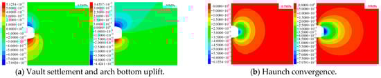
Figure 4.
Displacement cloud image under different uniaxial compressive strengths (Unit: m).
Figure 4 illustrates that increasing the surrounding rock uniaxial compressive strength leads to a progressive reduction in all displacement values: vault settlement, arch bottom uplift, and haunch convergence. The surrounding rock deformation demonstrates a strong negative relationship to uniaxial compressive strength, which is consistent with established principles. Within the range of 0.5 to 30 MPa, the settlement and uplift were even reduced by approximately 150 times. To better understand the effect of varying uniaxial compressive strengths on surrounding rock deformation in underground engineering, the peak values of vault settlement, arch bottom uplift, and haunch convergence from the simulation data were compiled for analysis, enabling plots of displacement variation under different strengths to be generated, as shown in Figure 5.
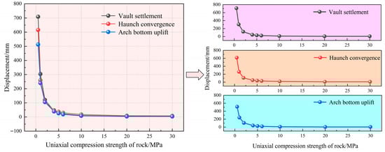
Figure 5.
Displacement variation curve of the surrounding rock with different uniaxial compressive strengths.
As can be seen from Figure 5, the decreasing pattern of the surrounding rock displacement is consistent. Taking the vault settlement displacement as an example: the displacement in the extremely soft rock range of less than 5 MPa shows a trend of sharp decline, dropping from 709.2 mm to 29.3 mm, a decrease of approximately 24 times; within the relatively soft rock range of 5~15 MPa, it is in a trend of slow decline; within the uniaxial compressive strength range of 15~30 MPa, the surrounding rock displacement is in a trend of stable development. The sensitivity of the surrounding rock displacement to the uniaxial compressive strength differs across various value ranges.
4.2. Influence of Elastic Modulus of Surrounding Rock
Based on the defined simulation range, a series of scenarios with varying elastic moduli was designed. Ten working conditions with elastic modulus of 0.5 GPa, 1 GPa, 1.5 GPa, 2 GPa, 3 GPa, 4 GPa, 5 GPa, 6 GPa, 8 GPa, and 10 GPa are designed. The uniaxial compressive strength, buried depth, stress factors, and construction factors are the same as those of the control group. Then, the underground engineering is excavated, and the cloud image after excavation is calculated. The displacement cloud image when the elastic modulus of the surrounding rock is 0.5 GPa and 10 GPa is shown in Figure 6.
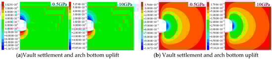
Figure 6.
Displacement cloud image under different elastic moduli (Unit: m).
In Figure 6, as the elastic modulus increases, the displacement values—vault settlement, arch bottom uplift, and haunch convergence—show a progressive reduction. The rock mass deformation and elastic modulus show a significant negative correlation, which conforms to the existing law. In the range of 0.5–10 GPa, the displacement of the three is reduced by about 20 times. The maximum displacement values were obtained and plotted against varying elastic moduli. As illustrated in Figure 7, the resulting deformation trends-namely, vault settlement, haunch convergence, and arch bottom displacement—all demonstrate a high degree of consistency. Taking the vault settlement displacement as an example, when the elastic modulus is less than 4 GPa, the vault settlement decreases from 1167.2 mm to 147.09 mm, a decrease of about 87%, and the downward trend is more pronounced. When the elastic modulus is 4–10 GPa, the vault settlement displacement decreases from 147.09 mm to 58.54 mm, with a decrease of about 60%. The downward trend is relatively gentle, and the development trend tends to converge. From the results, it can be observed that an increase in the surrounding rock’s elastic modulus significantly reduces deformation quantities such as vault settlement, arch bottom uplift, and haunch convergence. This indicates that material stiffness plays a critical role in controlling large deformations in deep soft rock. Boosting this property significantly enhances the structural integrity of the rock mass, consequently lowering the potential for failure. In practical engineering, this finding suggests that priority should be given to measures that increase the overall stiffness of the support system during design, such as optimizing the performance of lining materials or enhancing the strength of initial support.
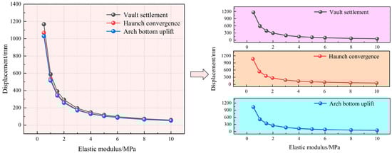
Figure 7.
Displacement variation curve of the surrounding rock with different elastic moduli.
4.3. Influence of Burial Depth
According to the above simulation range, the working conditions under different burial depths are designed. Six working conditions are designed for burial depths of 300 m, 600 m, 900 m, 1200 m, 1500 m, and 1800 m. The uniaxial compressive strength, elastic modulus, lateral pressure coefficient, and excavation methods are the same as those of the control group. Then, the underground engineering is excavated, and the cloud map after excavation is calculated. The displacement cloud map (Figure 8) is illustrated when the burial depth is 300 m and 1800 m.
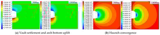
Figure 8.
Displacement cloud image under different burial depths (Unit: m).
As illustrated in Figure 8, increasing burial depth leads to progressively larger displacements in the form of vault settlement, arch bottom uplift, and haunch convergence. The deformation of the surrounding rock shows a significant positive correlation with buried depth, which is in line with the existing law. The maximum values of the three displacements in the simulation results are extracted, and the curves under various buried depths of underground engineering are drawn as shown in Figure 9. It can be seen from the figure that the settlement of the surrounding rock vault, the convergence of the haunch, and the uplift displacement of the arch bottom increase with the increase of buried depth. Taking the settlement displacement of the vault as an example, in the range of 300~1800 m, the settlement of the vault increases from 2.75 mm to 233.46 mm, an increase of about 85 times, and the rise of each buried depth section shows an increasing trend, indicating that the buried depth is very sensitive to the deformation of the surrounding rock. In deep underground engineering in soft rock strata, the surrounding rock is subjected to high geostatic stresses, significantly increasing the risk of major deformation. Therefore, sufficiently rigid support measures must be employed during the initial construction phase to effectively control excessive displacement.
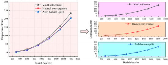
Figure 9.
Displacement variation curve of the surrounding rock with different burial depths.
4.4. Influence of Lateral Pressure Coefficient
According to the above simulation range, the working conditions under different lateral pressure coefficients are designed. The designed lateral pressure coefficients were 1, 1.25, 1.5, 1.75, 2, 2.25, and 2.5, totaling seven working conditions. The uniaxial compressive strength, elastic modulus, burial depth, and excavation method were the same as those of the control group. Subsequently, the excavation of the underground engineer was performed, and the nephograms of the surrounding rock deformation after excavation were calculated. The nephograms of surrounding rock displacement under lateral pressure coefficients of 1 and 2.5 are listed and shown in Figure 10.
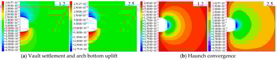
Figure 10.
Displacement cloud image under different lateral pressure coefficients (Unit: m).
As illustrated in Figure 10, as the lateral pressure coefficient increases, the displacement values, including vault settlement, arch bottom uplift, and haunch convergence, gradually increase. The surrounding rock deformation demonstrates a significant positive relationship to the lateral pressure coefficient. The maximum value of the displacement of the three in the simulation results is extracted, and the displacement curve of the surrounding rock under different lateral pressure coefficients is drawn as shown in Figure 11. Figure 11 demonstrates a corresponding growth in the displacements of the vault, haunch, and arch bottom as the lateral pressure coefficient increases, confirming a uniform trend in surrounding rock deformation. Taking vault settlement displacement as an example: in the range of lateral pressure coefficient of 1~2.5, the vault settlement increases from 45.9 mm to 273.35 mm, an increase of about 6 times, which is more sensitive to surrounding rock deformation.
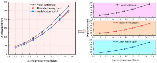
Figure 11.
Displacement curve of the surrounding rock with the pressure coefficient at different sides.
4.5. Influence of Excavation Method
According to the design of the above excavation method, different excavation methods are adopted to excavate the underground engineering and carry out the initial support. In the actual simulation, the parameters of the rock mass were replaced to approximate the effect of the initial support. The calculation model and excavation steps of different excavation methods are illustrated in Figure 12, and Table 4 presents the initial support parameters. The displacement of surrounding rock under different excavation methods is affected by the excavation steps and step length. Therefore, it is of great significance to study the displacement variation law and final deformation of each part to study the stability of the surrounding rock of underground engineering under different excavation methods. The monitoring points under the y = 5 m section are extracted, and the vault settlement, haunch convergence, and arch bottom uplift displacement are analyzed.
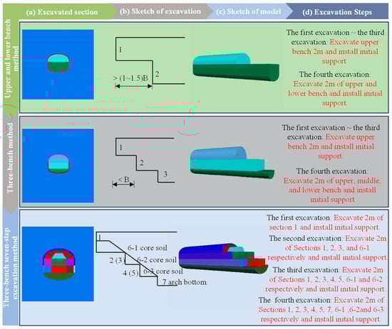
Figure 12.
Diagram of different excavation methods.
Table 4.
Mechanical parameters of initial support.
As shown in Figure 13a, the settlement of the vault under different excavation methods changes with the excavation step. From the diagram, it can be seen that the variation law of the vault settlement with the excavation step under the three excavation methods is similar, and the variation law of the vault settlement with the excavation step during the construction process can be summarized into three stages. The first stage is the advanced slow settlement. This stage is mainly due to the initial effect of the construction process on the rock mass in front of the tunnel face, which causes the stress redistribution of the upper surrounding rock and causes the rock mass in front of the tunnel face to settle first. The second stage is the excavation deformation stage. As the tunnel face progresses, the varied phases of the three excavation techniques start to exert influence on the overlying rock mass. The vault settlement generated under this disturbance is more obvious than the settlement generated in the first stage. And the vault settlement changes under the three methods began to distinguish, and the settlement value and deformation rate began to increase. The third stage is the deformation convergence stage.
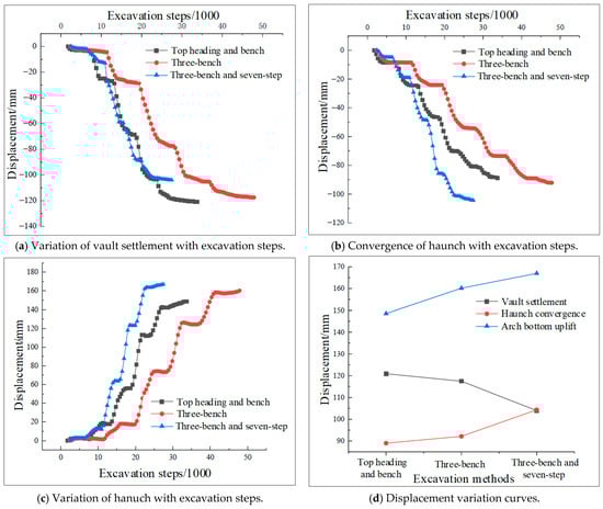
Figure 13.
Displacement variation curves under different excavation methods.
With continued excavation advance, the deformation rate decelerates markedly, eventually approaching zero, and the vault settlement reaches a stable value. Although the variation of vault settlement with excavation steps is consistent, there are still some gaps in the settlement value. Final vault settlement values of 120.90 mm, 117.48 mm, and 103.92 mm were recorded, corresponding to the three construction methods employed. The relationship between the vault settlement values under the three construction methods is that the upper and lower step method is the largest, and the three-bench seven-part excavation method is the smallest. The Three-Bench Method reduced the settlement value by 3.42 mm compared to the upper and lower bench method; the three-bench seven-step excavation method reduced the settlement value by 13.56 mm compared to the three-bench method. Among the three excavation methods, the upper and lower bench method has the greatest influence on vault settlement, whereas the three-bench seven-step method results in the least displacement.
As shown in Figure 13b, the change of haunch convergence with excavation steps under different excavation methods is shown. It can be seen from the figure that the variation law of the haunch convergence of the three construction methods with the excavation step is similar. The variation law of the haunch convergence with the excavation step during the construction process can be attributed to two stages: excavation deformation and deformation convergence. The final haunch convergence values of the three construction methods are 88.97 mm, 92.13 mm, and 104.32 mm, respectively. Haunch convergence values vary significantly among the methods: the three-bench, seven-part excavation shows the maximum settlement, whereas the upper- and lower-bench method shows the minimum values. The three-bench method shows a settlement reduction of 12.19 mm compared to the three-bench seven-part method, while the up-down-bench method exhibits a further 3.16 mm reduction relative to the three-bench method. It can be seen that under the three excavation methods, the three-bench seven-part excavation method has the greatest influence on the haunch convergence, and the up-down-bench has the least influence on the haunch. The reason is that the greater number of excavation steps in the three-bench seven-step excavation method prevents the initial support from forming a closed ring in a timely manner, resulting in a continuous increase in haunch convergence.
From the diagram (Figure 13c), it can be seen that the variation law of the arch bottom uplift with the excavation step under the three excavation methods is similar. The variation law of the arch bottom uplift with the excavation step during the construction process can be summarized into three stages: advanced deformation, excavation deformation and deformation convergence. The final arch bottom uplift values of the excavation methods are 148.53 mm, 160.17 mm, and 166.96 mm, respectively. Arch bottom uplift varies significantly among the methods: the three-bench seven-part excavation shows maximum settlement, whereas the upper and lower bench method demonstrates minimum values. Settlement using the three-bench seven-part method exceeded that of the three-bench method by 6.79 mm; similarly, displacement with the three-bench method was 11.64 mm higher than that of the upper and lower bench method. It can be seen that under the three excavation methods, the three-bench seven-part excavation method has the greatest impact on the arch bottom uplift, and the upper and lower steps have the least impact on the haunch. The reason is that the more excavation steps in the three-bench seven-part excavation method make the initial support not close in time. The ring causes the uplift displacement to continue to increase.
The deformation behavior of the surrounding rock across different regions under varied excavation methods is demonstrated in Figure 13d. The figure indicates a dominant influence of the upper and lower bench method on vault settlement, in contrast to the pronounced effect of the three-bench seven-part method on haunch convergence and arch bottom uplift. The reason is that the three-bench seven-part excavation method disturbs the surrounding rock more frequently, and the initial support is not closed in time, resulting in incomplete support. Owing to low initial support parameters and insufficient supporting strength, different excavation methods exert a limited influence on the variation range of these three displacement components. Table 5 presents a comparative summary of the results under various working conditions. In an actual project, different excavation methods and support measures should be selected according to different engineering geological conditions, so as to make it adaptable and reasonable.
Table 5.
Comparison table of excavation methods.
4.6. Influence of Supporting Mode
According to the design of the above working conditions, the deformation law of the surrounding rock of underground engineering under different support modes is simulated. Among them, the support mode one: spray layer; support mode two: spray layer and anchor cable (bolt); support mode three: spray layer and steel frame; support mode four: spray layer, anchor cable (bolt) and steel frame. Table 6 summarizes the parameters of the supporting structure. Regardless of the support mode used, excavation was carried out using the full-section method. The excavation footage is 2 m at a time, and three rows of anchor rods or three steel frames are applied during the footage. For the excavation and breakthrough of underground engineering, four different support modes were adopted for reinforcement, and the displacement nephograms of the cross-section at y = 5 m were obtained. The surrounding rock displacement nephograms under different support modes are shown in Figure 14. The simulated maximum displacements for all four support modes were compared, and their respective displacement variation curves are plotted in Figure 15.
Table 6.
Mechanical parameters of the supporting structure.
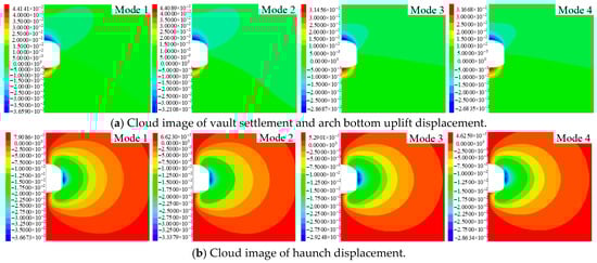
Figure 14.
Cloud image of surrounding rock displacement under different support modes (Unit: m).
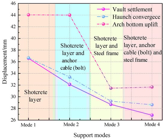
Figure 15.
Variation curves of surrounding rock displacement under different support modes.
As presented in Figure 15, from support mode 1 to support mode 4, both the vault settlement and the haunch convergence displacement exhibit a progressive reduction, with their variation trends showing strong consistency. This suggests that the supporting structure provides increasingly effective constraints on both the vault and haunch areas. Vault settlement showed a reduction of 9.75 mm, declining from an initial 36.59 mm to 26.84 mm. Compared to the impact of the aforementioned factors on vault settlement displacement, different support modes merely provide a supplementary constraint to the surrounding rock. This constraining effect is far less significant than the influence of material and stress factors. From the displacement change process from support mode 3 to support mode 4, it can be seen that the vault settlement decreased by only 1.85 mm, indicating that the support effect of underground engineering using mode 4 is excessive, which will lead to high construction and material costs. Under the second support mode, the absence of anchor rods at the arch bottom results in their inability to restrain uplift deformation. Therefore, the layout of anchor bolts requires careful consideration during actual construction. The displacement of the arch bottom uplift under the four different support modes decreased from 44.04 mm to 31.67 mm, a decrease of 12.37 mm, and the decrease was obvious, but the sensitivity of the support effect to the stability of the surrounding rock was soft.
4.7. Influence of Initial Support Timing
Using the above-designed working conditions, this simulation evaluates how initial support timing affects key point displacement in underground engineering. The analysis covers four stress release rates: 20%, 40%, 60%, and 80%, incremented at 20% intervals. The initial support adopts the spray layer support, and the relevant mechanical parameters are shown in Table 4. As shown in Figure 16, the displacement of the key points occurs when the stress release rate is 20% and 80%.
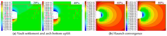
Figure 16.
Cloud image of surrounding rock displacement under different initial support timing (Unit: m).
It can be seen from Figure 16 that the vault settlement is 87.13 mm at an 80% release rate, and the vault settlement is 22.47 mm at a 20% release rate. The displacement at key points in the surrounding rock under an 80% stress release rate exceeds that observed at a 20% release rate. It shows that the initial support should not be constructed too late, but the initial construction time is not too early, resulting in the stress can not be released in time, the surrounding rock can not fully bear its own stress, so that the support structure bears a large stress, resulting in the cracking and falling of the initial support and other bad phenomena. The displacement of the surrounding rock during the construction of the initial support and the convergence of the displacement of the surrounding rock after the initial support are extracted (Figure 17a,b). Figure 17c illustrates the variation in displacement at key surrounding rock locations across different stress release rates. From the figure, it can be seen that the displacement of the vault by the initial support of 20% release rate increased by 19.8 mm, the displacement of the vault by the initial support of 40% release rate increased by 8.31 mm, the displacement of the vault by the initial support of 60% release rate increased by 4.63 mm, and the displacement of the vault by the initial support of 80% release rate increased by 2.52 mm. Delayed initial support installation progressively reduces vault settlement, haunch convergence, and arch bottom uplift. Consequently, initial support should be applied at a displacement release rate of 4060% to maximize the surrounding rock’s bearing capacity and control excessive deformation.
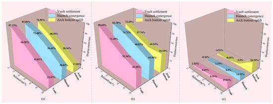
Figure 17.
The variation curve of initial support on surrounding rock displacement under different release rates: (a) Displacement of surrounding rock under initial support; (b) Displacement of surrounding rock after initial support; (c) The variation curve of initial support on surrounding rock displacement under different release rates.
In addition, to better illustrate the connection between the results of this study and practical projects, findings from the Haba Snow Mountain Tunnel on the Yunnan-Tibet Railway were introduced for comparison. With a maximum burial depth of 1155 m, the surrounding rock mainly consisted of weak formations such as schistose basalt and tuff, characterized by poor integrity and well-developed joints and fissures. During construction, under the combined influence of high in-situ stress and weak rock mass, the tunnel exhibited significant large deformation phenomena. Previous studies and monitoring results have shown that the deformation rate was relatively rapid in the early excavation stage, and gradually decreased with the progressive action of the initial support, eventually tending to converge [31,32,33]. This deformation behavior is consistent with the patterns observed in the numerical results of this paper, namely, rapid growth in the early stage followed by gradual stabilization. Such consistency indicates that the numerical results of this study are of engineering rationality and can provide references for the analysis of large deformation mechanisms and construction control in similar deep soft rock tunnels.
5. MSI Large Deformation Influence Factors Sensitivity of Soft Rock in Deep Underground Engineering
5.1. Method of Sensitivity Analysis
The first step of sensitivity analysis is to establish a system model (P is the system characteristic), and its benchmark parameter set is determined by the problem discussed [34]. This section focuses on evaluating the sensitivity of various factors affecting large deformation in deep underground surrounding rock, using actual reference values of uniaxial compressive strength, elastic modulus, and stress factors as the benchmark parameter set (α). When analyzing the influence of a parameter αk on the characteristic P, the remaining parameters can be taken as the reference value and fixed, so that αk changes within its possible range, and the relationship curve between the system characteristic P and the parameter αk can be drawn [35]. A minor alteration in αk resulting in a substantial variation in P indicates higher sensitivity of P to αk, whereas a diminished response signifies lower sensitivity (see Figure 18a). However, in practical systems, the parameters that govern system behavior are often distinct physical quantities with varying units. Consequently, their sensitivities cannot be directly compared using the aforementioned analysis. Therefore, dimensionless processing is required (see Figure 18b) [12]. According to the relationship obtained from the dimensionless treatment, the SK(αk)~αk curve can be further drawn to analyze the effect of an individual factor on surrounding rock stability (see Figure 18c). Among them, SK* consists of dimensionless, non-negative real numbers. By comparing the sensitivity factors corresponding to each parameter, the sensitivity of the system characteristics to each influencing factor can be obtained.
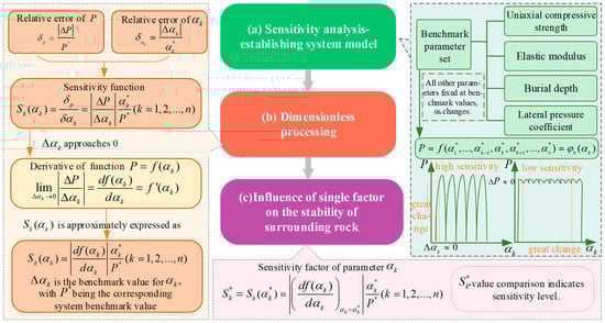
Figure 18.
Sensitivity analysis of influencing factors of soft rock material-stress large deformation.
5.2. Result of Sensitivity Analysis
The influencing factors of material-stress-induced large deformation disaster in deep underground engineering are divided into three aspects: material, stress and construction factors. Among them, material and stress factors are quantitative factors, and construction factors are qualitative factors, so it is difficult to quantify them. Therefore, drawing on the results from Section 4 regarding vault settlement, invert uplift, and haunch convergence under various factors, the sensitivity of four material and stress indexes to the stability of different parts of underground engineering is analyzed. When analyzing the sensitivity of uniaxial compressive strength, elastic modulus, and stress factors, it is necessary to first carry out dimensionless processing and map each influencing factor index to the range of 0~1. According to the vault settlement, haunch convergence, and arch bottom uplift, the stability dependent variables are plotted as illustrated in Figure 19.
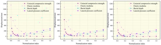
Figure 19.
Displacement curve of the surrounding rock under different factors.
As illustrated in Figure 19, the displacement of surrounding rock in different parts has regularity with the change of different indices. Under equivalent influencing conditions, the deformation exhibits the greatest magnitude in the vault settlement, followed by the haunch convergence, with the arch bottom uplift being the least significant. The same influencing factors have different displacement peaks for different surrounding rock parts. The influence of uniaxial compressive strength and elastic modulus on the stability of the surrounding rock has a negative correlation. From the perspective of displacement variation, the influence of elastic modulus is the most significant. From the perspective of displacement variation, its sensitivity to surrounding rock displacement is far less than that of material factors. The results indicate that greater buried depth and higher lateral pressure coefficient consistently lead to increased surrounding rock displacement. The four variation curves of vault settlement, haunch convergence and arch bottom uplift have the same intersection relationship, indicating that the sensitivity curve of each index to surrounding rock displacement is not affected by the location of the surrounding rock, and has the same change trend. Therefore, to study the sensitivity curve of each index to the displacement of surrounding rock, based on the principle of least square method, the relationship curves between the vault settlement value and the corresponding indexes (uniaxial compressive strength, elastic modulus, buried depth and lateral pressure coefficient) are fitted by power function, and the fitting fitness R2 is guaranteed to be greater than 0.99. Combining the quadratic polynomial obtained by fitting with the SK(αk) relationship (Figure 18c), the sensitivity coefficients of the vault settlement and their respective indicators can be obtained, as shown in Figure 20. It can be seen from the figure analysis that the elastic modulus is the most sensitive factor among the factors affecting the material-stress-induced large deformation. When the elastic modulus is less than 2 GPa, the sensitivity coefficient is still much higher than the effect of stress factors, which coincides with the current research on large deformation classification according to the elastic modulus index. Followed by uniaxial compressive strength, lateral pressure coefficient and buried depth. Therefore, the material properties of soft surrounding rock are the main controlling factors of large deformation of soft surrounding rock in deep underground engineering. In order to avoid large deformation, pre-grouting or pre-support measures, such as an advanced pipe shed, should be taken to reinforce the surrounding rock in advance.
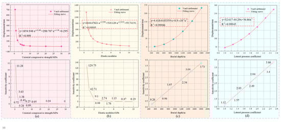
Figure 20.
Fitting curve and sensitivity coefficient of surrounding rock: (a) Uniaxial compressive strength; (b) Elastic modulus; (c) Burial depth; (d) Lateral pressure coefficient.
6. Discussion
This study employed a numerical simulation method to systematically investigate the influence factors and sensitivity of the large deformation of material-stress-induced soft rock in deep engineering. However, the results were obtained under the assumptions of an ideal elastoplastic constitutive model and specific boundary conditions, without considering the effects of groundwater, anisotropy, or long-term creep. These simplifications may, to some extent, limit the applicability of the findings to actual underground engineering projects. However, this study still provides a clear theoretical framework and analytical method basis for understanding soft rock’s large deformation mechanism. Future research could be further expanded based on the sensitivity analysis method established in this paper.
On the one hand, the existing model can be combined with the seepage-stress coupling theory to systematically study the strength deterioration law of soft rock and the deformation evolution mechanism of surrounding rock under the action of groundwater [36,37], so as to reveal the evolution law of large deformation of soft rock under complex hydrogeological conditions. On the other hand, based on the key material parameters (such as elastic modulus) identified in this paper, the sensitivity of the critical index of ‘2 GPa’ in different geological environments and its control on the stability of the surrounding rock can be discussed in depth. Therefore, it provides a more reliable theoretical basis for the long-term stability of surrounding rock in deep underground engineering under soft surrounding rock environments.
7. Conclusions
In this paper, the influence factors of soft rock material-stress-induced large deformation in deep underground engineering are classified into three categories and seven indices. Then, the three-dimensional finite difference method is used to design the numerical simulation test to study the deformation law characteristics of the surrounding rock under different material factors, different stress factors, and different construction factors. The sensitivity analysis, based on numerical test results, yields the following main conclusions:
- The large deformation of soft surrounding rock is divided into three categories: material-induced large deformation (material-stress-induced and material-chemical-induced), stress-induced large deformation, and structural-type large deformation. The material-stress-induced large deformation is a large deformation phenomenon of soft rock plastic flow or shear slip under the dual action of low rock material strength and high ground stress. The influencing factors of large deformation are divided into material factors, stress factors, and construction factors.
- The uniaxial compressive strength and elastic modulus of the material factors show a significant negative correlation with the deformation of the surrounding rock and eventually tend to converge. When the elastic modulus is less than 4 MPa, the settlement of the vault decreases by about 87%, and the downward trend is more severe. From the perspective of the overall displacement variation, the influence of elastic modulus is higher than that of uniaxial compressive strength; The stress factors have a significant positive correlation with the deformation of the surrounding rock. With the increase of stress factors, the displacement of surrounding rock will continue to increase in a relatively stable range. Material and stress factors differentially affect the peak displacement of various surrounding rock components. The vault settlement displacement is the most obvious, followed by the haunch convergence displacement, and the last is the arch bottom uplift displacement.
- The vault settlement, haunch convergence, and arch bottom uplift under different excavation methods of construction factors could be categorized into three phases: advanced deformation stage, excavation deformation stage, and deformation convergence stage, but the excavation methods are less sensitive to the surrounding rock displacement. The effect of the supporting mode on the displacement is limited. Support Mode 4 (shotcrete layer, anchor cables/bolts, and steel frames) provides excessive support strength. The optimal timing for initial support should be when the surrounding rock stress release ratio reaches 40–60%, as this approach both fully utilizes the self-bearing capacity of the rock mass and effectively controls harmful deformation.
- Sensitivity analysis of the MSI deformation factors reveals that varying values of a single factor exert differing degrees of influence on surrounding rock stability. The elastic modulus has the strongest influence on the displacement of the surrounding rock. When the elastic modulus is less than 2 GPa, the sensitivity coefficient is much higher than the stress factors. The material factors of soft surrounding rock serve as the primary determinant for large deformation. In practice, to avoid large deformations during construction in soft surrounding rock strata, it is essential to promptly install 20 mm diameter anchor bolts with a yield strength of 335 MPa and 18.9 mm diameter anchor cables, combined with shotcrete support immediately after excavation. This effectively controls surrounding rock deformation. Additionally, pre-grouting or advanced support measures such as umbrellas (pipe roofing) can be adopted to reinforce the rock mass.
Author Contributions
Conceptualization, J.G. and Y.L.; Methodology, Y.Y., J.G. and Y.L.; Software, Y.L., L.L. and B.Q.; Validation, J.G. and Y.Y.; Formal Analysis, L.L.; Investigation, Y.L. and J.G.; Resources, J.G. and B.Q.; Data Curation, Y.L.; Writing—Original Draft, Y.Y., J.G. and Y.L.; Writing—Review and Editing, L.L., Y.L. and J.G.; Visualization, Y.Y. and B.Q.; Supervision, B.Q.; Project Administration, Y.Y. All authors have read and agreed to the published version of the manuscript.
Funding
This study was supported by the Henan Province University Science and Technology Innovation Team Project (Grant No. 25IRTSTHN006), the Opening Project of Key Laboratory of Highway Bridge and Tunnel of Shanxi Province (Chang’an University) (Grant No. 300102211517), and the Enterprise Commissioned Project (Grant No. H20-411).
Data Availability Statement
The original contributions presented in this study are included in the article. Further inquiries can be directed to the corresponding author.
Conflicts of Interest
Author Yang Yu was employed by the company Henan First Geological and Mineral Investigation Institute Co., Ltd. The remaining authors declare that the research was conducted in the absence of any commercial or financial relationships that could be construed as a potential conflict of interest.
References
- Cui, J.; Broere, W.; Lin, D. Underground space utilisation for urban renewal. Tunn. Undergr. Space Technol. 2021, 108, 103726. [Google Scholar] [CrossRef]
- Gu, J.H.; Guo, J.Q.; Zhu, Z.H.; Sun, F.Y.; He, B.G.; Zhang, H.Y. Sensitivity Analysis on Influential Factors of Strain Rockburst in Deep Tunnel. Buildings 2024, 14, 2886. [Google Scholar] [CrossRef]
- Guo, J.Q.; Sun, F.Y.; Liu, X.L.; Tian, Y.C.; He, B.G. Evolution characteristics of rockburst considering grain size and excavation unloading using 3D polycrystalline discrete element method. Bull. Eng. Geol. Environ. 2024, 83, 376. [Google Scholar] [CrossRef]
- Zhang, X.G.; Liang, J.H.; Wei, G.; Liang, C.K.; Yan, L.; Han, W.; Zhang, Y.D.; Tian, Y.Z.; Zhang, H. Study on the Bearing Characteristics of a Novel Inner Support Structure for Deep Foundation Pits Based on Full-Scale Experiments. Buildings 2025, 15, 2887. [Google Scholar] [CrossRef]
- Chen, J.X.; Liu, W.W.; Chen, L.J.; Luo, Y.B.; Wu, Y.F. Field test on large deformation control and reasonable support form of large-span highway tunnel in chlorite schist stratum. China J. Highw. Transp. 2020, 33, 212–223. [Google Scholar]
- Tan, Z.S.; Zhao, J.P.; Zhang, B.J. Study on large deformation mechanism and control technology of super deep buried soft rock tunnel-Taking the Haba Snow Mountain Tunnel of Lixiang Line of Yunnan-Tibet Railway as an example. Chin. J. Undergr. Sp. Eng. 2024, 44, 2307–2315. [Google Scholar]
- Zhao, C.Y.; Lavasan, A.A.; Hölter, R.; Schanz, T. Mechanized tunneling induced building settlements and design of optimal monitoring strategies based on sensitivity field. Comput. Geotech. 2018, 97, 246–260. [Google Scholar] [CrossRef]
- Cui, J.; Yao, Z.G.; Yu, T.; Wang, J.F.; Ying, K.C.; Liu, B.; Zhu, S.; Yan, X.N. Soil Displacement of Slurry Shield Tunnelling in Sandy Pebble Soil Based on Field Monitoring and Numerical Simulation. Buildings 2024, 14, 3043. [Google Scholar] [CrossRef]
- Zhang, S.; Rodriguez-Dono, A.; Song, F.; Zhou, Z.L. Time-dependent tunnel deformations: Insights from in-situ tests and numerical analyses. Tunn. Undergr. Space Technol. 2025, 157, 106319. [Google Scholar] [CrossRef]
- Yang, Z.M.; Zhang, Y.F.; Li, J.; He, J.J.; Zhang, S.J. Study on the sensitivity of inverted arch uplift mechanism and influencing factors of red-bed soft rock tunnel in Northwest China. Mod. Tunnel. Technol. 2025, 62, 11–18. [Google Scholar]
- Zhu, Z.G.; Li, W.J.; Liu, Z.C.; Sun, M.L.; Wu, J. Analysis of extrusion deformation characteristics of tunnel face in weak surrounding rock tunnel. Chin. J. Undergr. Sp. Eng. 2017, 13, 711–716+736. [Google Scholar]
- Li, Y.X.; Zhang, Z.M.; Dong, J.Y.; Wang, B.B.; Wang, C. Study on the Impact of Groundwater and Soil Parameters on Tunnel Deformation and Sensitivity Analysis. Appl. Sci. 2024, 14, 8196. [Google Scholar] [CrossRef]
- Zhao, G.B. Deformation Characteristics and Parameter Sensitivity Analysis of Surrounding Rock in Shield Construction of Fault Fracture Zone; Guangzhou College: Guangzhou, China, 2024. [Google Scholar]
- Yang, Y.S.; Zhang, D.M.; Chen, X.; Zhao, Y. Sensitivity analysis of rock mechanics parameters in stability of tunnel surrounding rock. Energy Sources Part A 2024, 46, 2567–2580. [Google Scholar] [CrossRef]
- Sun, L.C.; He, Y.L.; Xu, H.Y. Sensitivity analysis of tunnel construction to weathered argillaceous sandstone stratum. Nat. Def. Transp. Eng. Technol. 2023, 21, 32–35+51. [Google Scholar]
- Deng, S.E.; Zhang, H.S.; Pang, Q.; Li, Z.; Li, F.F. Comprehensive Evaluation of Sensitivity of Surrounding Rock Parameters for Underground Powerhouse Experience Support. IOP Conf. Ser. Earth Environ. Sci. 2020, 570, 062049. [Google Scholar] [CrossRef]
- Liu, X.R.; Han, Y.F.; Li, D.L.; Tu, Y.L.; Deng, Z.Y.; Yu, C.T.; Wu, X.C. Anti-pull mechanisms and weak interlayer parameter sensitivity analysis of tunnel-type anchorages in soft rock with underlying weak interlayers. Eng. Geol. 2019, 253, 123–136. [Google Scholar] [CrossRef]
- Chen, F.F.; Zhang, Z.Q.; Li, N. Sensitivity analysis of the influences of rock mechanical parameters on the deformation of underground caverns. Appl. Mech. Mater. 2013, 275, 262–268. [Google Scholar]
- Zhang, S.S.; Pei, X.J.; Mu, J.Q.; Wang, R.K.; Ran, C.Y.; Cui, C.W.; Li, P.F.; Zhao, X.P. Evolution mechanisms analysis of Xingguangsanzu toppling deformation bodies under condition of impound water of Xiluodu hydropower station. Chin. J. Rock Mech. Eng. 2015, 34, 4091–4098. [Google Scholar]
- Zhang, J.Z.; Zhou, X.P. Forecasting catastrophic rupture in brittle rocks using precursory AE time series. J. Geophys. Res. Solid Earth. 2020, 8, e2019JB019276. [Google Scholar] [CrossRef]
- Wang, H.L.; Wu, Y.Z.; Li, M.; Liu, Y.X.; Xu, W.Y.; Yan, L.; Xie, W.C. A novel FDEM-GSA method with applications in deformation and damage analysis of surrounding rock in deep-buried tunnels. Tunn. Undergr. Space Technol. 2024, 154, 106106. [Google Scholar] [CrossRef]
- Liu, Y.T.; Zheng, P.Q.; Wang, P. Multi-factors influence of anchorage force on surrounding rock under coupling effect of creep rock mass and bolt/cable. Geomat. Nat. Hazards Risk. 2021, 12, 328–346. [Google Scholar] [CrossRef]
- Zhou, C.; Gao, W.; Hu, C.J.; Chen, X.; Cui, S. Numerical study of related factors affecting mechanical properties of fractured rock mass and its sensitivity analysis. Comput. Part. Mech. 2023, 3, 369–386. [Google Scholar] [CrossRef]
- Wang, C.H.; Sha, P.; Hu, Y.F.; Li, C.S.; Guo, Q.L. Study on the extrusion deformation of tunnel surrounding rock. Rock Soil Mech. 2011, 32, 143–147. [Google Scholar]
- Qiu, J.; Tian, X.J.; Chen, T. Large Deformation Characteristics and Formation Mechanism of a Soft Rock Railway Tunnel in Southwest China. Chin. Water Transp. 2018, 18, 203–205. [Google Scholar]
- Wang, J.; Li, T.B.; Cheng, Q.; Zhao, H. Study on large deformation mechanism and treatment measures of soft rock in Xuecheng tunnel of G317 line. Site Invest. Sci. Technol. 2018, 29–35. [Google Scholar]
- Xu, G.W.; He, C.; Dai, C.; Wang, Y. Study on large deformation failure mechanism and excavation method of soft rock tunnel under complex geological conditions. Mod. Tunnel. Technol. 2017, 54, 146–154. [Google Scholar]
- Li, C. Study on Large Deformation Mechanism of a Soft Rock Tunnel in Cheng-Lan Railway; Chengdu University of Technology: Chengdu, China, 2019. [Google Scholar]
- Wang, D.; Jiang, Y.J.; Sun, X.M.; Luan, H.J.; Zhang, H. Nonlinear large deformation mechanism and stability control of deep soft rock roadway: A case study in China. Sustainability 2019, 11, 6243. [Google Scholar] [CrossRef]
- Chen, Y.M.; Xu, D.P. Foundation and Engineering Example of FLAC/FLAC3D, 2nd ed.; China Water Resources and Hydropower Publishing House: Beijing, China, 2013; pp. 131–164.
- Zhao, J.P.; Tan, Z.S.; Zhang, B.J.; Wang, F.X. Stress-Release Technology and Engineering Application of Advanced Center Drifts in a Super-Deep Soft-Rock Tunnel: A Case Study of the Haba Snow Mountain Tunnel. Rock Mech. Rock Eng. 2024, 57, 7103. [Google Scholar] [CrossRef]
- Zhao, J.P.; Tan, Z.S.; Liu, X.L.; Zhang, B.J. Investigation of active and passive radial deformation control techniques for deeply buried soft rock tunnels: A case study of the Haba Snow Mountain Tunnel on the Yunnan-Tibet Railway. Tunn. Undergr. Space Technol. 2025, 165, 106903. [Google Scholar] [CrossRef]
- Zhao, J.P.; Tan, Z.S.; Liu, X.L.; Zhang, B.J.; Xie, W.Q.; Ma, Q. Large deformation characteristics and mechanisms of deep-buried foliated basalt tunnel: A case study of the HABA snow mountain tunnel. Rock Mech. Rock Eng. 2025, 3, 3523–3544. [Google Scholar] [CrossRef]
- Zhang, Z.G.; Zhang, M.; Wang, Y.H.; Wei, L.; Zhang, L.; Leng, B.; He, Y. Study on Deformation Characteristics of Surrounding Rock in Deep-Buried Tunnels of Plateau Railroads. Adv. Civ. Eng. 2025, 2025, 5549827. [Google Scholar] [CrossRef]
- Jiang, Y.; Zou, W.D. Sensitivity analysis of factors affecting the stability of deep buried tunnel. Sustainability 2022, 15, 381. [Google Scholar] [CrossRef]
- Xu, Y.; Rui, R.; Wang, J.Y. Recommended strategies for assessing and managing groundwater dewatering during subsurface construction in sediments adjacent to large river systems: Examples from Wuhan in China. Environ Earth Sci. 2021, 80, 69. [Google Scholar] [CrossRef]
- Valenta, J.; Verner, K.; Martínek, K.; Hroch, T.; Buriánek, D.; Megerssa, L.A.; Bohác, J.; Kassa, M.; Legesse, F.; Yakob, M.; et al. Ground fissures within the Main Ethiopian Rift: Tectonic, lithological and piping controls. Earth Surf. Process. Landforms. 2021, 15, 3158–3174. [Google Scholar] [CrossRef]
Disclaimer/Publisher’s Note: The statements, opinions and data contained in all publications are solely those of the individual author(s) and contributor(s) and not of MDPI and/or the editor(s). MDPI and/or the editor(s) disclaim responsibility for any injury to people or property resulting from any ideas, methods, instructions or products referred to in the content. |
© 2025 by the authors. Licensee MDPI, Basel, Switzerland. This article is an open access article distributed under the terms and conditions of the Creative Commons Attribution (CC BY) license (https://creativecommons.org/licenses/by/4.0/).