Article

Research on the Leakage Effect of Shield Tunnels in Water-Rich Silty Clay Strata Based on On-Site Investigation and Numerical Simulation

1
School of Civil Engineering, Xi’an University of Architecture and Technology, Xi’an 710055, China
2
Shaanxi Key Laboratory of Geotechnical and Underground Space Engineering, Xi’an 710055, China
3
Xi’an University of Architecture and Technology Engineering Co., Ltd., Xi’an 710055, China
*
Author to whom correspondence should be addressed.
Buildings 2025, 15(21), 3867; https://doi.org/10.3390/buildings15213867
Submission received: 9 September 2025 / Revised: 16 October 2025 / Accepted: 21 October 2025 / Published: 26 October 2025

Abstract

Based on a metro project in Hangzhou, combined with the investigation of on-site seepage and leakage problems and finite element numerical simulation, the influence of local seepage and leakage in shield tunnels in water-rich silty clay strata on stratum settlement and lining structure deformation was studied. During the simulation process, two working conditions, namely leakage at the joint of the segment and local damage leakage, were, respectively, set up to analyze the distribution of pore water pressure, the development characteristics of stratum settlement and the response of the lining structure. The results show that the pore water pressure near the leakage area is significantly reduced. The pore pressure at the joint of the segment and the local leakage position is reduced by 81.22% and 76.88%, respectively, compared with the hydrostatic pressure at the same burial depth, and the reduction at the bottom of the model is 11.45% and 6.46%, respectively. Under different working conditions, the settlement rates all increased first and then tended to stabilize. The maximum surface settlements were 91 mm and 32 mm, respectively, and the former exceeded the control value. The surface settlement of local leakage is distributed in a concave pattern, and the peak settlement is located directly above the leakage point. The lining structure deforms significantly in both the upper and lower directions, both shifting downward towards the stratum. The maximum displacement and deformation caused by the leakage at the joint of the segment reached 78.26 mm and 24.38 mm, respectively, with obvious over-limits. It is recommended to prioritize the sealing treatment of the leakage area at the joint. The research results can provide theoretical references for the control of water leakage and structural safety evaluation of shield tunnels in water-rich and weak strata.

1. Introduction

With the continuous development of China’s economy and the accelerating process of urbanization, the urban population density has been constantly increasing, and the development and utilization of underground space resources have been continuously strengthened. The construction of various underground infrastructures such as subway tunnels, comprehensive pipe galleries, and water transmission pipelines has been rapidly advancing, becoming an important support system for urban development. Among them, the shield method has become one of the primary construction techniques for urban subway tunnels due to its high efficiency, minimal disturbance to the ground surface, and strong safety performance.
In the current design and construction of shield tunnel projects in China, single-layer segment linings are commonly adopted. However, during tunnel construction and operation, various factors including design deficiencies, poor construction control, environmental erosion, and accidental impacts may lead to different degrees of structural damage and water leakage. Such leakage not only threatens tunnel durability and operational safety but can also trigger secondary disasters such as excessive ground settlement and structural deformation. Recent studies have revealed that leakage-induced soil–structure interactions can significantly modify the mechanical behavior of both the tunnel lining and the surrounding strata [1,2,3].
In addition to domestic projects, international investigations have also demonstrated that leakage and associated ground deformation are global concerns in shield tunneling. For instance, Macchiarulo et al. [4] integrated MT-InSAR (PS-InSAR) with structural evaluation to assess tunneling-induced deformations on 858 buildings along London Crossrail, revealing that traditional greenfield assessment methods tend to overestimate structural damage. Afshani et al. [5] developed a joint drainage model for segmented tunnels in cohesive soils, incorporating circumferential joint opening effects validated through field data and finite element analysis, and identified critical opening thresholds based on contact pressure criteria. Furthermore, Banerjee and Sikdar [6] investigated land subsidence during Kolkata’s East–West Metro tunneling, where TBM intrusion into an unmapped aquifer triggered aquitard–aquifer leakage, deformation, and building damage, elucidating the coupled hydrogeological mechanisms involved. These studies provide valuable international perspectives for understanding leakage-induced deformation and long-term performance of shield tunnels under diverse geological and hydrological conditions.
Consequently, numerous studies have focused on both clarifying the mechanisms of shield tunnel leakage and developing effective mitigation measures, covering aspects from detection and rapid repair to numerical modeling and long-term structural assessment.
Early studies primarily focused on the mechanisms and remediation of leakage phenomena. Wang et al. [7] investigated leakage at the junction between shafts and shield tunnels in the Beijing area and proposed a rapid repair method using a novel cement-based material with superior underwater non-dispersibility, which effectively controlled structural leakage. Guo et al. [8] conducted numerical simulations and model tests to analyze the diffusion behavior of grout in both dense and loose soils, providing optimized guidance for grouting hole spacing and overall scheme design. These works established a foundation for improving leakage treatment through enhanced grouting techniques and material innovation.
Building on this, a growing body of research has combined advanced monitoring and data-driven detection technologies to improve leakage identification accuracy. Shen et al. [9] explored karst-induced leakage defects in the Nanshibi Tunnel and proposed an integrated “grouting–lining replacement–inverted arch” strategy to mitigate recurrent leakage. Lin et al. [10] further combined ground-penetrating radar (GPR) with finite-difference time-domain (FDTD) modeling and enhanced back-projection imaging to detect lining cavities and evaluate grouting effectiveness, establishing quantitative interpretation criteria. These integrated detection and treatment approaches mark an important step toward intelligent maintenance of tunnel waterproofing systems.
Meanwhile, the application of machine learning and computer vision has greatly advanced automatic leakage diagnosis. Jiang et al. [11] proposed a hybrid ensemble deep learning framework, Boosted Bagging, achieving precise semantic segmentation of tunnel point clouds. Similarly, Wang et al. [12] introduced a water leakage sensing network (WLAN) that significantly improved segmentation accuracy and reduced prediction errors, while Wang et al. [13] developed the improved Cascade-MRegNetX model, enhancing detection accuracy and generalization capability. The integration of intelligent sensing and deep learning has thus provided new possibilities for real-time, high-precision leakage monitoring.
In addition to detection and treatment research, recent efforts have also shifted toward understanding the underlying mechanisms of leakage through coupled numerical analyses. Liu et al. [14] employed a coupled hydro-mechanical model with a fines-sensitive constitutive relationship to explore the influence of internal erosion on tunnel lining behavior, showing that neglecting erosion can underestimate lining stress and ground settlement. Park [15] developed a Python-based TOUGH-FLAC simulator that quantified the influence of leakage rate and position on ground deformation and lining stability, elucidating key mechanical–hydraulic coupling mechanisms. Shi et al. [16] further conducted model tests using a self-developed dual-line shield tunneling setup to examine ground settlement and pipeline deformation under leakage and non-leakage conditions, establishing and validating a 3D leakage diffusion model. These studies provided critical insights into the hydro-mechanical interactions governing leakage-induced deformation in shield tunnels.
Beyond short-term mechanical responses, attention has also been directed toward long-term deformation behavior and structural stability under leakage conditions. Mu et al. [17] combined numerical simulation with field monitoring to develop an RFPA-based long-term deformation model for heterogeneous rheological rock, proposing control principles for time-dependent damage and implementing a “yielding bolt–W strip–shotcrete” support system. Gong et al. [18] analyzed leakage characteristics during the operation of a large-diameter underwater shield tunnel across the Yangtze River and proposed comprehensive countermeasures such as backfill grouting, joint grouting, bolt-hole sealing, and gasket enhancement. These findings highlight that long-term monitoring and deformation control are vital to ensuring the service performance of tunnels subjected to leakage.
In summary, although significant progress has been made in leakage detection, mechanism analysis, and structural response assessment, systematic investigations combining both domestic and international experiences are still limited, particularly regarding the ground settlement behavior and lining deformation characteristics of shield tunnels in water-rich silty clay strata. In particular, the coupled effects of local leakage on surrounding soil deformation and tunnel lining performance during operation have not been sufficiently clarified. Therefore, this paper, based on field investigations and numerical simulations of a representative metro tunnel section in Hangzhou, explores the influence of local leakage in water-rich silty clay strata on ground settlement and lining structural response, aiming to provide theoretical insight and engineering guidance for the prediction, evaluation, and prevention of leakage in shield tunnels.

2. Overview of the Test Site

The test site is based on a certain Metro Line 7 project in Hangzhou City, China. The first work area includes the section from Aoti Station to Jianshe 4th Road Station, Jianshe 4th Road Station, and two stations and three sections from Jianshe 4th Road Station to Mingxing Road Station. The shield tunnel sections mainly pass through important buildings and structures such as rivers, highways, and airport viaducts, and the construction environment is complex. The total length of the shield tunnel section on the right line is 1392.164 m, and that on the left line is 1363.391 m. Figure 1 shows the monitoring section from Jianshe 4th Road Station to Mingxing Road Station, while Figure 2 presents a typical cross-section of the shield tunnel and surrounding stratum for clearer illustration.
The burial depth range of the tunnel lining segments in the test section is 10–18 m, the outer diameter of the segments is 6.20 m, the inner diameter is 5.85 m, the lining thickness is 350 mm, and the width of each ring is 1220.6 mm. The lining adopts a six-piece segment assembly method, with the rings arranged alternately along the longitudinal direction, forming a structural system with relatively high overall rigidity.
This shield tunnel section passes under several important obstacles such as Jianshe Third Road, Wujia River (with a width of approximately 10 m and a water depth of 1 to 2 m), boao Road and xingyi Road. Two curve sections are set in the entire section, and their curve radii are R = 500 m and R = 700 m, respectively. According to the detailed investigation data, the water system of the test site is well-developed, with dense rivers along the line. The types of groundwater include pore water from loose rocks, pore confined water, and fissure water from bedrock. Submersion is mainly found in shallow (middle) fill layers and silty soil layers, with an annual water level variation of approximately 1.0 to 1.5 m. After water quality analysis, it is found that shallow diving has a slight corrosive effect on concrete. Under the effect of dry-wet cycling, it has a weak to moderate corrosive effect on the steel bars in reinforced concrete structures.
The stratum where this section is located is a typical water-rich silty clay stratum, featuring high water content, high compressibility and poor permeability. It is prone to induce tunnel seepage and leakage and related structural and stratum response problems, and has significant research value.

3. On-Site Investigation and Analysis of Segment Damage and Leakage

For the leakage phenomenon of the lining structure caused by problems such as segment damage or concrete spalling in the hole area during the operation of shield tunnels, on-site detection can be carried out based on actual projects. Combined with the shield construction parameters, a systematic analysis of the correlation between segment damage and the tunneling state can be conducted [6,7,19,20].

3.1. Analysis of Segment Damage

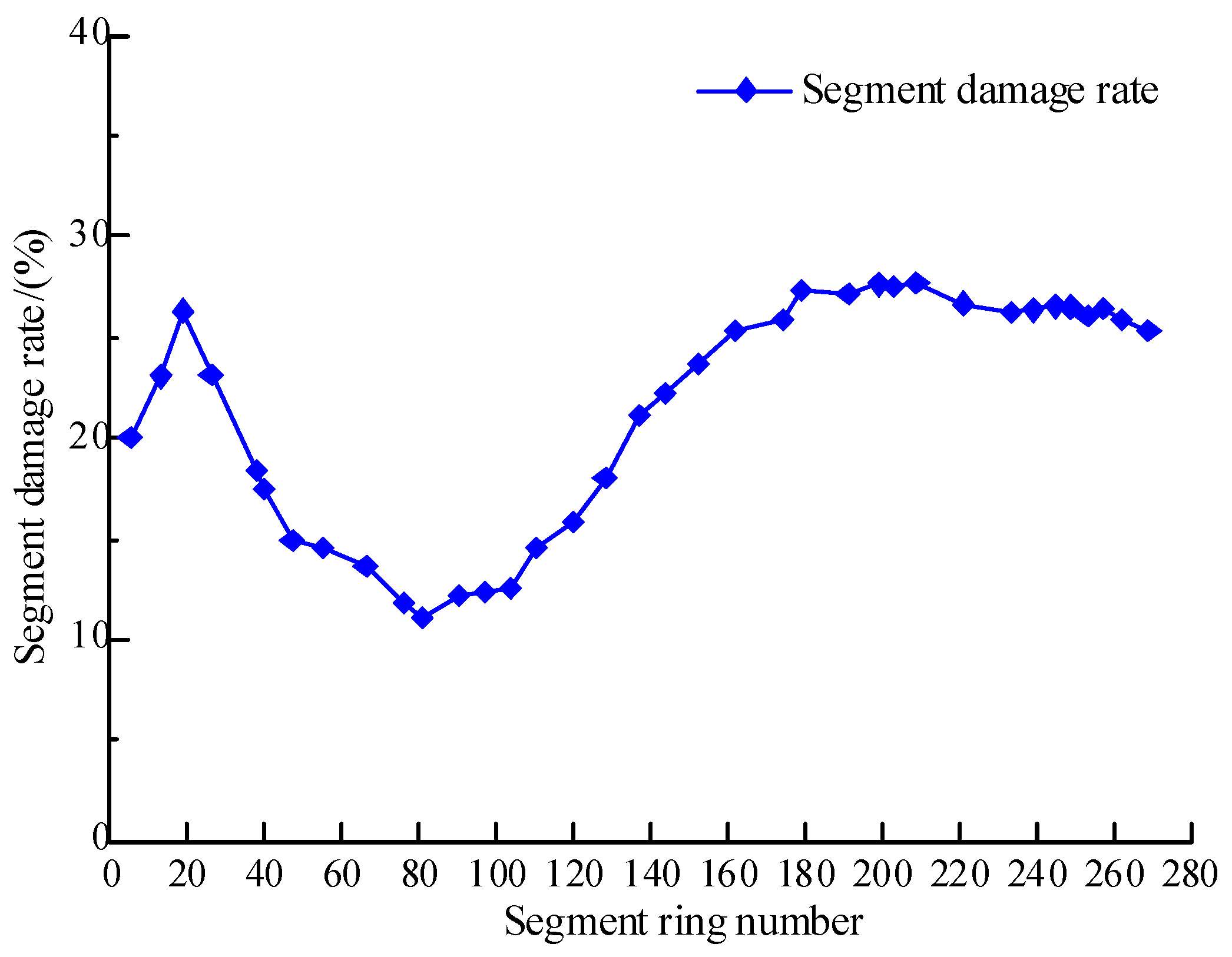
During the shield tunnel construction of this project, a systematic on-site inspection was carried out on the damage of the tunnel lining segments within the test section. By calculating the proportion of the number of damaged segments between each section to the cumulative number of excavation rings in that section, the segment damage rate of each section was calculated, and the variation curve of the segment damage rate within the test section was plotted, as shown in Figure 3.
As can be seen from Figure 3, in the early stage of shield tunneling, due to the unstable tunneling parameters, the shield posture control fluctuated greatly, resulting in a large upward displacement of the lining segments, causing abnormal force on the local ring surface and a short-term upward trend in the damage rate. When the tunneling reached around the 80th ring, the parameters of the shield machine gradually stabilized, the posture was well controlled, and the segment damage rate dropped to 12.5%. Subsequently, when the excavation reached the vicinity of the 100th ring, the vertical displacement of the shield tail increased to 30 mm. To control this trend, the site adopted the method of increasing the head and arranging counterweights at the middle shield position to lower the overall shield posture below the design axis. However, during the posture adjustment process, the vertical displacement difference between the head and tail of the shield machine increased, resulting in uneven force distribution on the lining ring surface and causing extensive segment damage, with the damage rate rising to 27.75%. After continuing the excavation to the 180th ring, the posture adjustment work was basically completed. The excavation mode was changed to the thrust mode, and the excavation state tended to stabilize. The number of damaged segments decreased accordingly and showed a gradually stabilizing trend.

3.2. Analysis of Segment Leakage

The leakage situation of the tunnel lining segments within this test section was systematically detected and statistically analyzed. The statistical results show that the leakage phenomenon mainly occurs in the middle and upper parts of the segment, and is mainly divided into two types: leakage at the segment joint and leakage caused by local damage to the segment. Among them, joint leakage includes circumferential and longitudinal joint leakage, while local damage leakage is mainly manifested as cracks on the outer arc surface of the segment, corner damage, concrete breakage in circumferential bolt holes, and concrete cracking in hoisting holes, etc.
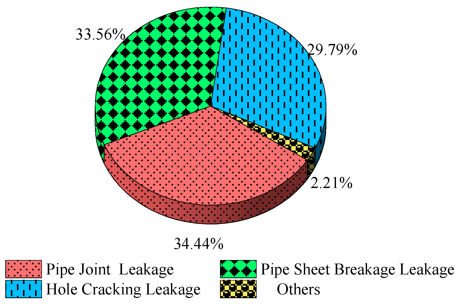
To facilitate the formulation of targeted leakage sealing schemes, this paper classifies the leakage types of tunnel lining structures into three categories: ① Joint leakage, such as circumferential joint leakage, longitudinal joint leakage, etc. ② Self-damage and leakage, such as corner damage, structural cracking, etc. ③ Hole cracking and leakage, such as leakage at bolt holes and hoisting holes, etc. Detailed statistical data on various types of leakage are shown in Table 1, and the distribution of leakage sites is illustrated in Figure 4.
As can be seen from Table 1 and Figure 4, the leakage problems of the lining segments in the test section mainly focus on joint leakage and self-damage leakage, which together account for 68% of the total leakage. Analysis of its causes reveals that this section is located in a water-rich silty clay stratum. At the initial stage of the shield machine’s excavation, the segments have just separated from the shield tail, and the initial setting of the grouting has not yet been completed. The buoyancy formed by the combined action of groundwater and slurry acts on the lining segments, making it difficult for their own weight and the overlaid load to counteract the buoyancy, thus causing the segments to float up and misposition. Ultimately, it induces problems such as joint leakage and structural damage leakage. Therefore, when conducting shield tunnel construction in water-rich silty clay strata, the following measures are recommended to reduce the risk of leakage:
During the construction process, the shield tunneling parameters should be strictly controlled to effectively control the floating amount of the segments.
After the excavation is completed, the areas where leakage has occurred should be promptly treated to stop the leakage.
During the operation stage of the tunnel, special attention should be paid to the long-term impact of joint leakage and damage leakage on the durability of the tunnel. Regular special inspection and maintenance treatment work should be carried out to ensure structural safety and service life.

4. Finite Element Simulation of Leakage Effect in Shield Tunnels

4.1. Tunnel Seepage Field Simulation

To explore the seepage behavior and soil response characteristics of water leakage in shield tunnels in water-rich silty clay strata, this paper uses ABAQUS 2021 finite element software to establish a three-dimensional solid–liquid coupling model. The model grid adopts C3D8P elements, that is, eight-node hexahedral solid elements with pore pressure calculation capability, which can be used for saturation-unsaturated seepage and formation mechanical response analysis.
The essence of seepage field simulation is to numerically solve the differential equation that controls the movement of groundwater under different boundary conditions. The seepage boundary of the stratum where the shield tunnel is located mainly includes the surface free drainage boundary and the seepage boundary at the tunnel lining. During the modeling process, the types of boundary conditions mainly consider the following three:
(1)
The first type of boundary condition (Dirichlet boundary): Specifies the water head value on the boundary;
(2)
The second type of boundary condition (Neumann boundary): Specifies the seepage rate or flow rate per unit area on the boundary;
(3)
The third type of boundary condition (natural boundary): It refers to the situation where there is neither water pressure nor seepage in the normal direction of the boundary (i.e., adiabatic or impermeable boundary).
Based on the on-site working conditions, this paper adopts the first type of boundary conditions to set the seepage boundaries of the surface and the seepage points. The pore water movement behavior in the groundwater–soil system is described by the Forchheimer seepage model, which can reflect the nonlinear seepage characteristics. During the coupled calculation process, ABAQUS binds the grid to the soil skeleton, allowing the liquid to flow freely in the pores. The soil stress is solved using Bishop’s effective stress principle.

4.2. Selection of Soil Parameters and Constitutive Models

The seepage behavior of soil is directly influenced by its physical-mechanical properties. In recent years, scholars at home and abroad have widely adopted the Mohr-Coulomb model [21,22], the Modified Cam-Clay model [23], and the model based on the Mohr-Coulomb model in the seepage simulation of shield tunnels. This paper does not involve external construction loads. It only simulates the soil response under the combined action of self-weight and seepage. Therefore, the Mohr-Coulomb model is selected to describe the stress–strain relationship of silty clay.
The soil permeability characteristic parameters include permeability coefficient, porosity ratio and saturation, which are assigned values based on the survey data and indoor test results. To account for the natural variability of silty clay, a sensitivity analysis was further performed by varying these parameters by ±20% around their mean values. The results showed that such variations had no significant impact on the overall deformation and seepage trends, confirming the robustness of the adopted parameters.
According to the fact that the test area is water-rich silty clay and the overall permeability of the stratum is relatively weak, considering the working condition where the energy of the tunnel seepage water is fully released to the stratum, the leakage point is assumed to be fully permeable, representing a conservative upper-bound scenario for leakage assessment. Field observations from metro tunnels in Hangzhou and similar studies [14,18] indicate that leakage usually occurs at segment joints or gasket defects, where the waterproofing function locally fails and the permeability approaches that of the surrounding soil. To further evaluate this assumption, a sensitivity analysis was performed by assigning partial permeability ratios (i.e., k1/kS = 0.1, 0.3, and 0.5). The results show that while reduced permeability slightly decreases the seepage flux and local settlement, the overall deformation pattern remains consistent, confirming the physical reasonableness and robustness of the fully permeable assumption. In the model, the permeability coefficient of the lining structure at the segment k1 is therefore set equal to the permeability coefficient of the surrounding soil kS, that is, k1/kS = 1.

4.3. Modeling of Lining Structure and Simplification of Stiffness

The lining structure of the shield tunnel is composed of reinforced concrete segments, which have relatively high rigidity and a force response close to linear. In this paper, it is simplified to a linear elastic body, and its mechanical behavior is simulated by using a linear elastic constitutive model [24]. Due to the large frictional resistance between the soil and the lining, there is no relative sliding between the structure and the soil [25]. In the model, the contact relationship is defined through the “binding” method [26].
(1)
Overall stiffness reduction method: Previous studies have demonstrated that the global stiffness of shield tunnels with staggered joint assembly is typically 70–80% of the designed stiffness because of the discontinuous circumferential connections between segmental rings. Kavvadas et al. [27] established three-dimensional finite element models of segmental linings with various joint configurations and found that the effective stiffness of staggered-joint linings approaches about 70–80% of the design stiffness. Similarly, Zhang et al. [28] conducted full-scale tests and iterative analyses of quasi-rectangular shield tunnels, further confirming this stiffness range. Referring to these studies and the design data of the present section, the reduced overall elastic modulus was set to 26.80 GPa, corresponding to approximately 75% of the design stiffness.
(2)
Joint stiffness weakening method: Experimental and numerical investigations have indicated that the stiffness of circumferential joints is substantially lower than that of the segment bodies, typically one to two orders of magnitude smaller. Liu et al. [29] analyzed leakage-induced deformation in shield tunnels and found that insufficient joint stiffness can cause ring dislocation, while Kou et al. [26] confirmed through simulation that joint bending stiffness under ultra-high water pressure conditions is 1–2 orders of magnitude below that of the segments. Based on these findings, a 6 mm-wide joint zone was introduced into the continuous lining model, and its elastic modulus was appropriately weakened to maintain the overall stiffness at about 0.75 of the design value. In the model, the elastic modulus of the segment body is set to 31.50 GPa, and that of the joint area is set to 0.5 GPa.

4.4. Model Establishment

According to the engineering geological investigation and detailed survey data of this test section, the upper cover soil of the site mainly includes miscellaneous fill soil, plain fill soil and sandy silt soil. The main strata that the shield tunnel passes through are sandy silt soil, silt sand, silty clay, silty clay, etc., and some strata contain silt layers.
The physical and mechanical parameters of the main strata were primarily obtained from the in situ engineering geological investigation and laboratory tests of soil samples collected from the project site. To ensure the accuracy and representativeness of the adopted values, the parameters were further compared and verified with previously published data on similar silty clay strata in the Hangzhou area reported by Mei et al. [30] and Yu et al. [31]. The detailed parameters are shown in Table 2.
To simplify the modeling process and reasonably reflect the seepage and leakage effect of the shield tunnel lining structure, the following assumptions and treatments were made for the stratum and structure in the numerical simulation: ① The model is a three-dimensional solid–liquid coupling model, and the mechanical response of the soil only considers the coupling effect of vertical gravity load and seepage force. ② According to the geological survey data, the terrain along the tunnel is relatively undulating, so the surface can be simplified to a horizontal plane. ③ In the model, six typical and representative main strata are selected, and the soil parameters are taken as the average values within the depth range of each layer, based on the verified dataset described above. ④ The lining structure is modeled based on a uniformly distributed leakage pattern, and the leakage area is assumed to be completely permeable.
In the three-dimensional finite element modeling research of tunnel water seepage and leakage, the setting of model dimensions should satisfy the basic principle that “boundary effects can be ignored” [32]. Referring to the modeling method of leakage simulation of the shield tunnel of Tianjin Metro by Zheng Gang et al. [33,34], the model extends 11.5 times the tunnel diameter on each side of the tunnel axis and 10 times the tunnel diameter vertically. Wang Honggang et al. [19,35] suggested that the model take the midline as the reference in the vertical tunnel cross-section direction, and take 10 times the diameter in each horizontal direction, with the bottom extending 5 times the diameter downward.
Based on the above studies and in combination with the stratum characteristics, tunnel size and burial depth conditions of the test area, the finite element model established in this paper extends 10 times the tunnel diameter on each side of the vertical tunnel section direction with the centerline as the reference, and extends 5 times the tunnel diameter from the bottom of the model downward from the center of the tunnel.
According to the engineering design data, the burial depth of the shield tunnel in the test section is approximately 14 m, with an outer diameter of 6.4 m, an outer diameter of the lining structure of 6.2 m, a length of 1.2 m for each ring of segments, a concrete strength grade of C50, corresponding to an elastic modulus of 3.45 × 10⁴ MPa, a Poisson’s ratio of 0.2, and a density of 2500 kg/m3.
Through the above modeling strategies, the groundwater migration and soil response of shield tunnels after local leakage occurs in water-rich strata can be simulated relatively realistically, providing reliable numerical basis for subsequent deformation analysis and risk assessment.

4.5. Simulation of Water Leakage Process in Shield Tunnels

Many scholars have conducted extensive research on the problem of water leakage in the lining structure of shield tunnels. One group of researchers [36,37,38,39,40] argues that, immediately after simulating the tunnel excavation and construction process, the seepage and leakage of the shield tunnel lining structure should be simulated. In contrast, another group of researchers [9,10,19,20,41] suggests that leakage defects in shield tunnels mainly occur during the operational stage after construction is completed, and numerical simulation of leakage should be performed only after the pore water pressure and stress redistribution reach a relatively balanced state.
According to relevant engineering research data, the leakage defect of shield tunnels usually gradually emerges after the construction is completed. With the passage of time, the combined effect of the aging of the sealing gasket between the lining segments, the deterioration of the performance of the grouting material at the shield tail, and the expansion of the segment joints caused by the non-uniform settlement of the soil has made the problem of leakage and seepage increasingly serious. In addition, the finite element method can be used not only to simulate the shield construction process but also to analyze the defects or damages during the operation period of tunnels. Therefore, in some studies, it is difficult to determine whether the response of the stratum and structure is caused by construction disturbances or seepage and leakage defects [42].
This paper aims to explore the influence of water leakage in shield tunnels on the settlement of the surrounding strata and the deformation of the lining structure. Therefore, the finite element model established in this paper does not take into account the influence of the shield tunnel excavation construction process, but only focuses on the leakage condition of the lining structure. Its numerical analysis mainly includes the following two steps:
(1)
Eliminate the influence of construction disturbances: The excavation of shield tunnels can cause stratum disturbances and stress redistribution, leading to initial settlement and deformation of the soil around the tunnel. To eliminate the interference of this factor, this paper first extracts the initial stress field of the soil caused by shield excavation and introduces it as the initial stress condition for seepage and leakage analysis into the finite element model, so that the node stress reaches a static equilibrium state, thereby eliminating the influence of the shield construction process on the seepage and leakage simulation results.
(2)
Numerical simulation of seepage and leakage defect: In the simulation of seepage and leakage conditions, the drainage boundary conditions at the leakage location of the shield lining structure are first activated, and the seepage duration is set. Regarding the selection of seepage stabilization time, Liu et al. [40] set the seepage duration as 10,000 days in their study. Zheng et al. [33,34] conducted the analysis over 200 days. Wang et al. [19,35] pointed out that the seepage stability time of different strata varies significantly, mainly constrained by the soil permeability coefficient. Based on the geological investigation data of this project and the test results of the basic physical and mechanical properties of the water-rich silty clay, the seepage duration in the finite element model was set to 3650 days. This value was determined considering the permeability and consolidation characteristics of the stratum, which are consistent with the findings of Mei et al. [30] and Cui et al. [43] in similar geological environments. Moreover, the rationality of this parameter has been further verified through the comparative analysis between the simulated and measured soil settlement presented in Section 4.7.

4.6. Numerical Simulation Working Condition Settings

Zhang et al. [44] conducted on-site monitoring of seepage and leakage defects in metro tunnels in the Shanghai area. The results showed that approximately 87% of the leakage defects occurred at the joints of the segments, among which the proportion of circumferential joint leakage reached 60%. Liu et al. [40] conducted on-site investigations of water leakage in metro shield tunnels based on actual engineering projects and analyzed that the proportion of water leakage at the joints of the segments accounted for as high as 85% of the total water leakage points. This paper conducts a statistical analysis of the leakage of segments within the test section. The results show that the leakage is mostly concentrated at the joints of segments and the damaged positions of segments, accounting for 68% of the total leakage points. Therefore, in the numerical simulation of the impact of seepage and leakage in the lining structure on metro tunnels during the operation period, two typical working conditions are mainly considered: seepage and leakage at the joint of the segments and local damage-induced leakage.
In the numerical simulation of water seepage and leakage in shield tunnels, to balance the calculation accuracy and computational load, predecessors mostly adopted symmetrical simplified modeling. Bao Heli et al. [45] adopted a half-symmetrical area model for the lining structure of shield tunnels in soft soil areas and set the model boundary in the horizontal direction about four times the tunnel diameter from the center of the left tunnel. When Wang Honggang et al. [19,35] simulated the leakage at the joint of the segment, considering the calculation scale, the longitudinal length was set at 15 m. When simulating local seepage and leakage, to reduce the influence of the boundary on the seepage and leakage response, the longitudinal length is taken to be 10 times the diameter of the tunnel.
(1)
Working Condition 1: Simulation of leakage at the joint of the segment
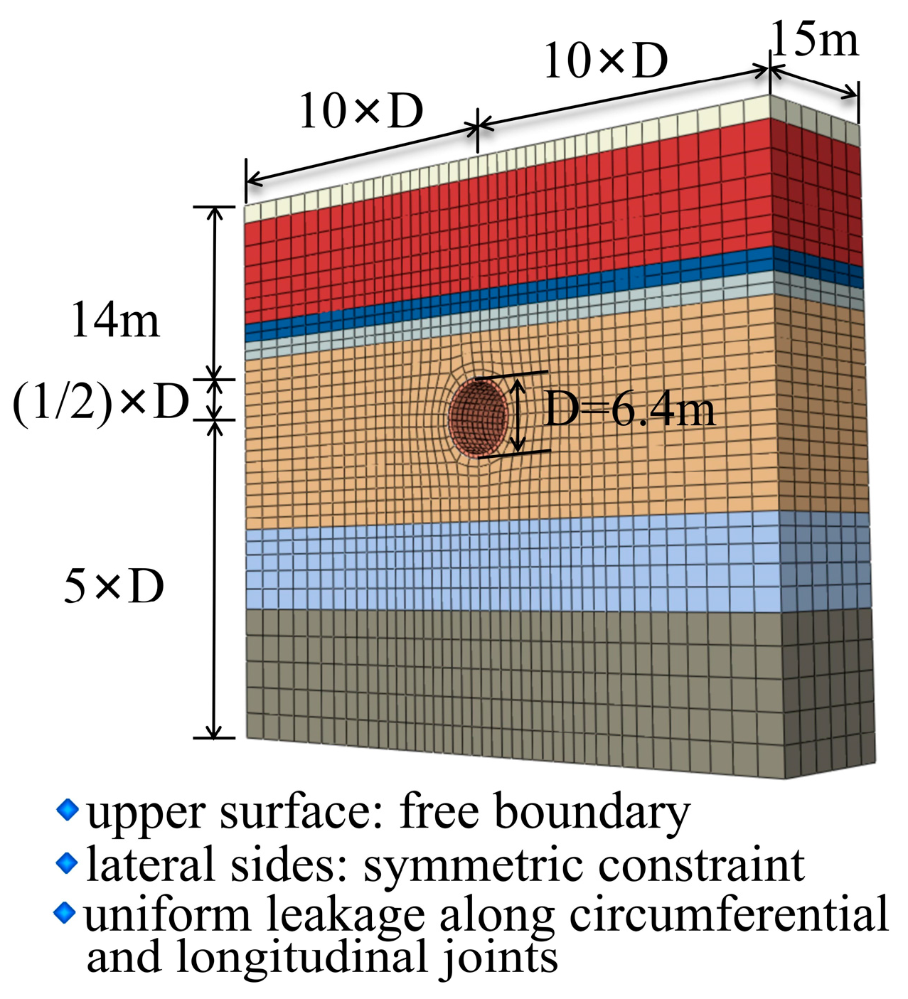
The joints of shield tunnel segments include two types: circumferential joints and longitudinal joints. According to the on-site investigation data, both types account for a relatively high proportion of the total leakage points. Therefore, this working condition takes into account the influence of both circumferential and longitudinal seam leakage simultaneously. In the finite element model, the leakage locations are set at the circumferential and longitudinal seams of the segments. It is assumed that the leakage water is uniformly distributed on the circumferential and longitudinal seams of the entire circumferential segment, and the seams are uniformly arranged in the longitudinal direction of the tunnel. Considering that the influence of model length on the analysis results is relatively small, this paper adopts 15 m as the longitudinal length of the model and constructs a three-dimensional finite element model as shown in Figure 5.
(2)
Working Condition 2: Simulation of local leakage in the segment
In addition to leakage at the joints, the lining structure of shield tunnels may also experience local leakage due to cracking of segments, damage to grouting holes or damage to corners and edges. This working condition is modeled by taking the damage and leakage of two adjacent longitudinal lining segments as an example. The model assumes that the leakage water is uniformly distributed in the local areas of the two ring segments, and the segment joints are still uniformly set along the longitudinal direction. To reduce the interference of boundary effects on local leakage simulation, the longitudinal length of the model was set to 10 times the tunnel diameter, that is, 60 m, equivalent to the length range of 50 ring segments. The established three-dimensional finite element model is shown in Figure 6.
To enhance methodological clarity, the main assumptions and limitations of the numerical simulation are summarized in Table 3. This summary clarifies the modeling framework and defines the conditions under which the simulation results remain valid.
The numerical model was developed using ABAQUS to simulate local seepage and leakage conditions under typical hydraulic parameters. The soil consolidation behavior was represented by equivalent elastic-plastic parameters calibrated from laboratory tests and empirical data. Although the current simulation focuses on spatial deformation responses, the calibration of the consolidation coefficient (cv) and incorporation of time-series monitoring data will be further explored in subsequent studies to enhance the temporal accuracy and reliability of the model.

4.7. Correctness Verification of the Model

(1)
On-site monitoring plan for shield tunnels
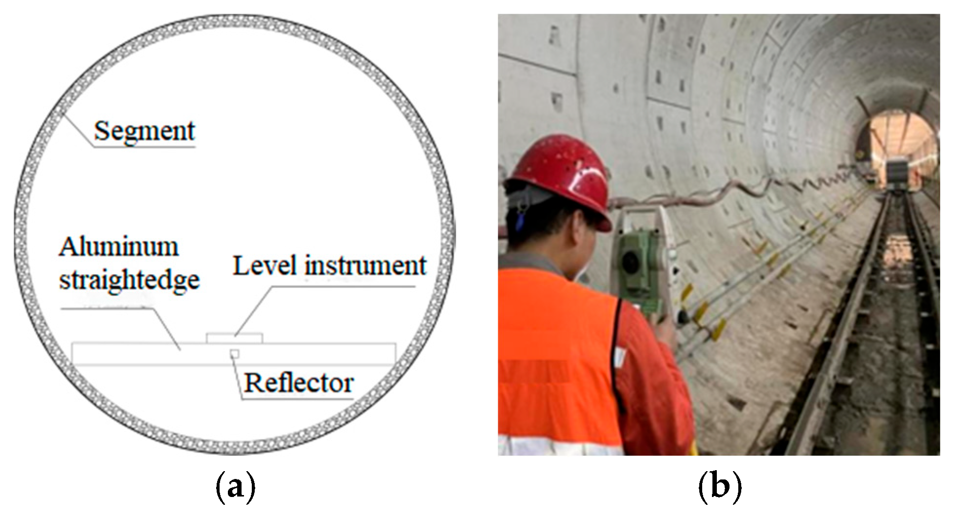
For the monitoring of the center coordinates of the pipe ring, the instruments used include a level, a level, an aluminum ruler and a reflector, as shown in Figure 7. First, stick the reflective sheet at the midpoint of the aluminum ruler and measure its three-dimensional coordinates. Subsequently, by combining the radius of the segment and the length of the level, the distance from the reflector to the center of the circle is calculated, thereby obtaining the measured three-dimensional coordinates of the center of the tube ring. By comparing the measured coordinates with the designed coordinates, the displacement information of the segments in all directions can be obtained.
For the monitoring of vertical and horizontal displacements of the segments, when measuring, place an aluminum ruler horizontally at the bottom of the segment, calibrate it with a level, and attach a reflective sheet at its center. 45 h after the segments are assembled and removed from the shield tail, the elevation of the reflector is measured using a level, and the vertical deviation of the shield tail of the shield machine is recorded simultaneously. The floating amount of the segments can be obtained by comparing the two. In addition, at the 2nd, 4th, 6th, 8th, 10th, 15th, 20th, 25th, 35th and 45th hours after the segments were removed from the shield tail, the vertical deviations of the segments in the key study sections were tracked and measured using the same method.
(2)
Comparative analysis of monitoring data for shield tunnels
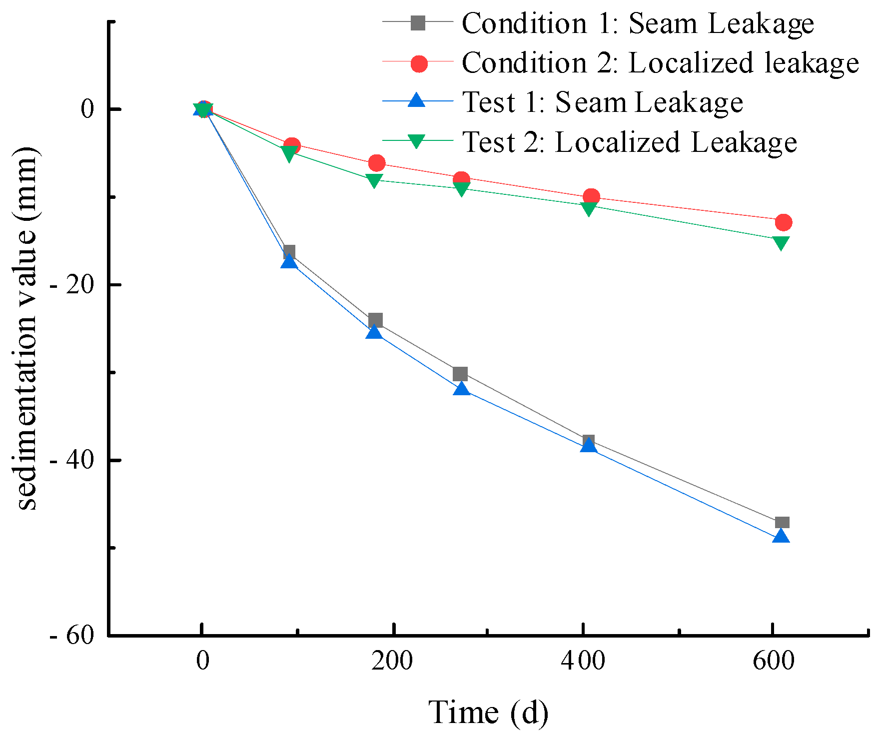
To verify the accuracy of the numerical simulation results, a 600-day soil settlement monitoring was carried out on the target section. The measured data was compared and analyzed with the finite element simulation results. Figure 8 shows the comparison of measured and simulated ground settlement over 600 days. As can be seen from Figure 8, the simulation results are in good quantitative agreement with the on-site measured data under both working conditions. The root mean square error (RMSE) between the measured and simulated settlements is 2.27 mm, corresponding to 4.64% of the maximum observed settlement. This indicates that the established finite element model has high reliability and engineering applicability.
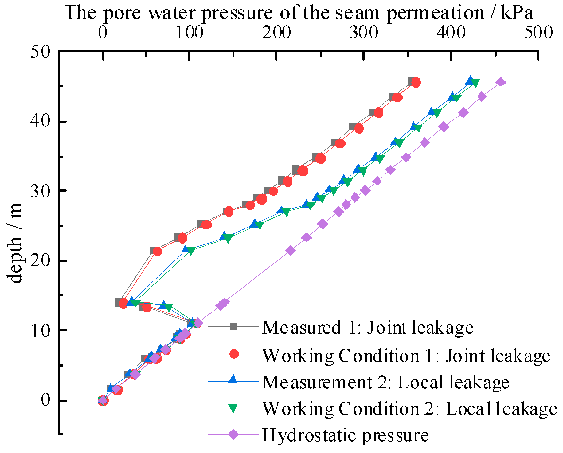
Furthermore, to further verify the reliability of the model comprehensively, the measured and simulated pore water pressures at day 600 were compared, as shown in Figure 9. It can be observed that the simulated pore water pressure curves closely match the field measurements at different depths. The average deviation between measured and simulated results is less than 3.0 kPa, and the RMSE value is 2.36 kPa, accounting for only 5.2% of the maximum observed pore pressure. This demonstrates that the numerical model can effectively capture the coupled variation in hydraulic and mechanical responses under joint and local leakage conditions, further confirming its reliability and accuracy.

5. Analysis of Numerical Results

The numerical results were analyzed mainly to investigate the deformation and response mechanism of the tunnel and surrounding soil under different seepage and leakage conditions. It should be noted that the present study primarily focuses on the spatial deformation characteristics rather than a systematic sensitivity analysis of hydraulic and structural parameters. The influence of key parameters such as permeability coefficient and lining stiffness will be examined in future research to further validate the robustness of the numerical model.

5.1. The Influence of Different Seepage and Leakage Conditions on the Pore Water Pressure of the Surrounding Soil

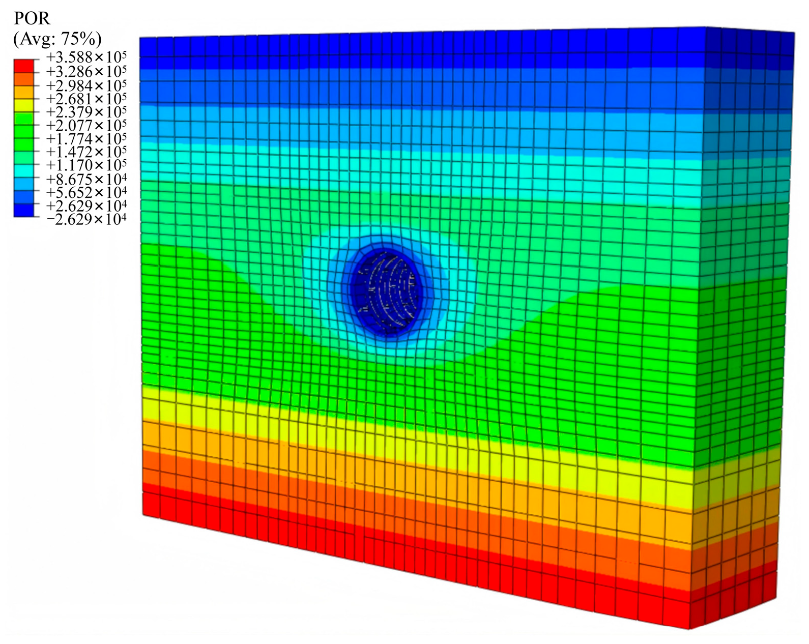
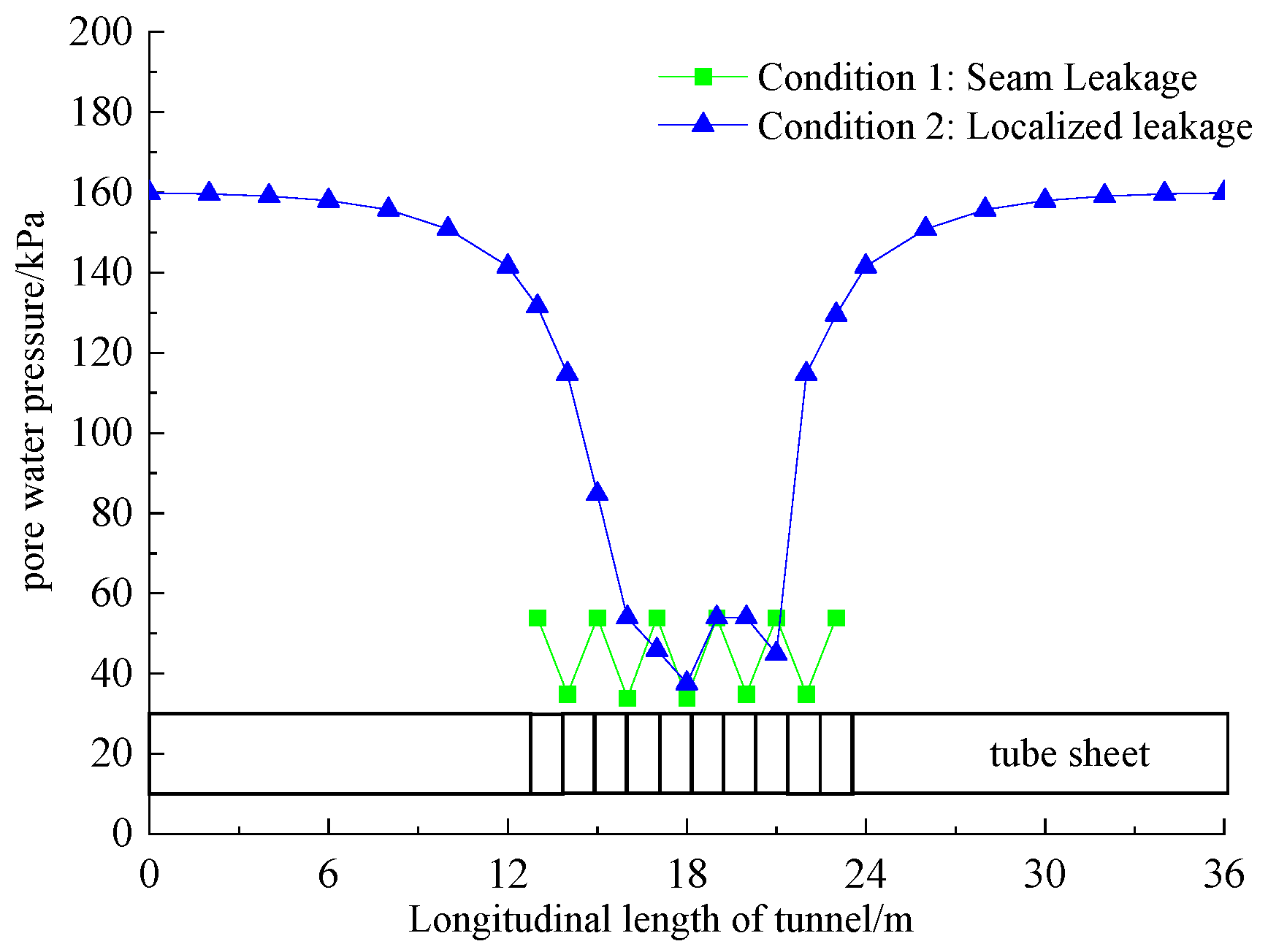
Under the two working conditions of segment joint leakage and local leakage, the pore water pressure distribution of the soil is shown in Figure 10 and Figure 11, respectively [46]. The results show that when joints or local leakage occur in the tunnel lining structure, the pore water pressure near the leakage location significantly decreases, and the farther away from the leakage location, the smaller the impact. Under the above two working conditions, typical sections were selected, respectively, and the pore water pressure data along the depth direction of the soil layer were extracted. The curves of pore water pressure varying with depth under different leakage conditions were plotted as shown in Figure 12. Furthermore, the pore water pressure distribution data in the longitudinal direction of the tunnel were extracted, respectively, and the variation curves along the axial direction of the tunnel were plotted as shown in Figure 13.
It can be seen from Figure 12 that the pore water pressure at the leakage locations has decreased significantly. Specifically, under the condition of leakage at the joint of the segment, the reduction in pore water pressure compared to the hydrostatic pressure at the same depth can reach 81.22%, while under the condition of local leakage, the reduction is 76.88%. With the increase in soil depth, the influence of seepage and leakage on pore water pressure gradually weakens. The pore water pressure reduction in the area located at the bottom of the model and far from the leakage position is 11.45% and 6.46%, respectively.
It can be further seen from Figure 13 that the leakage at the joint of the segment leads to a significant reduction in the pore water pressure at its location. Under the local leakage condition, there is also a relatively obvious attenuation of pore water pressure near the two loop segments where leakage occurs, and its influence range gradually weakens as the distance from the leakage location increases. From the overall trend, the degree of reduction in pore water pressure caused by local leakage is slightly less than that caused by joint leakage.

5.2. The Influence of Different Seepage Conditions on the Settlement of Soil Around the Tunnel

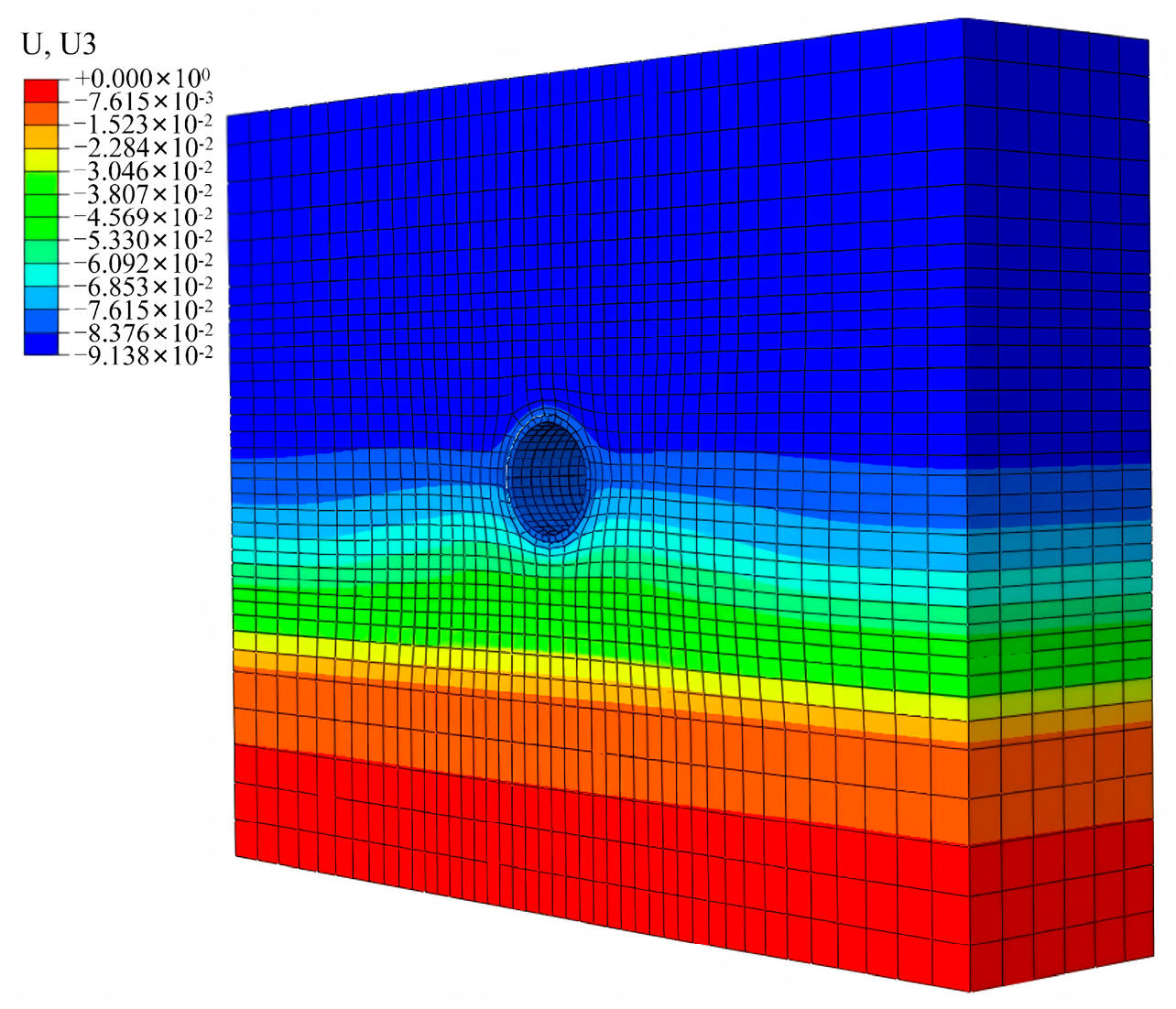
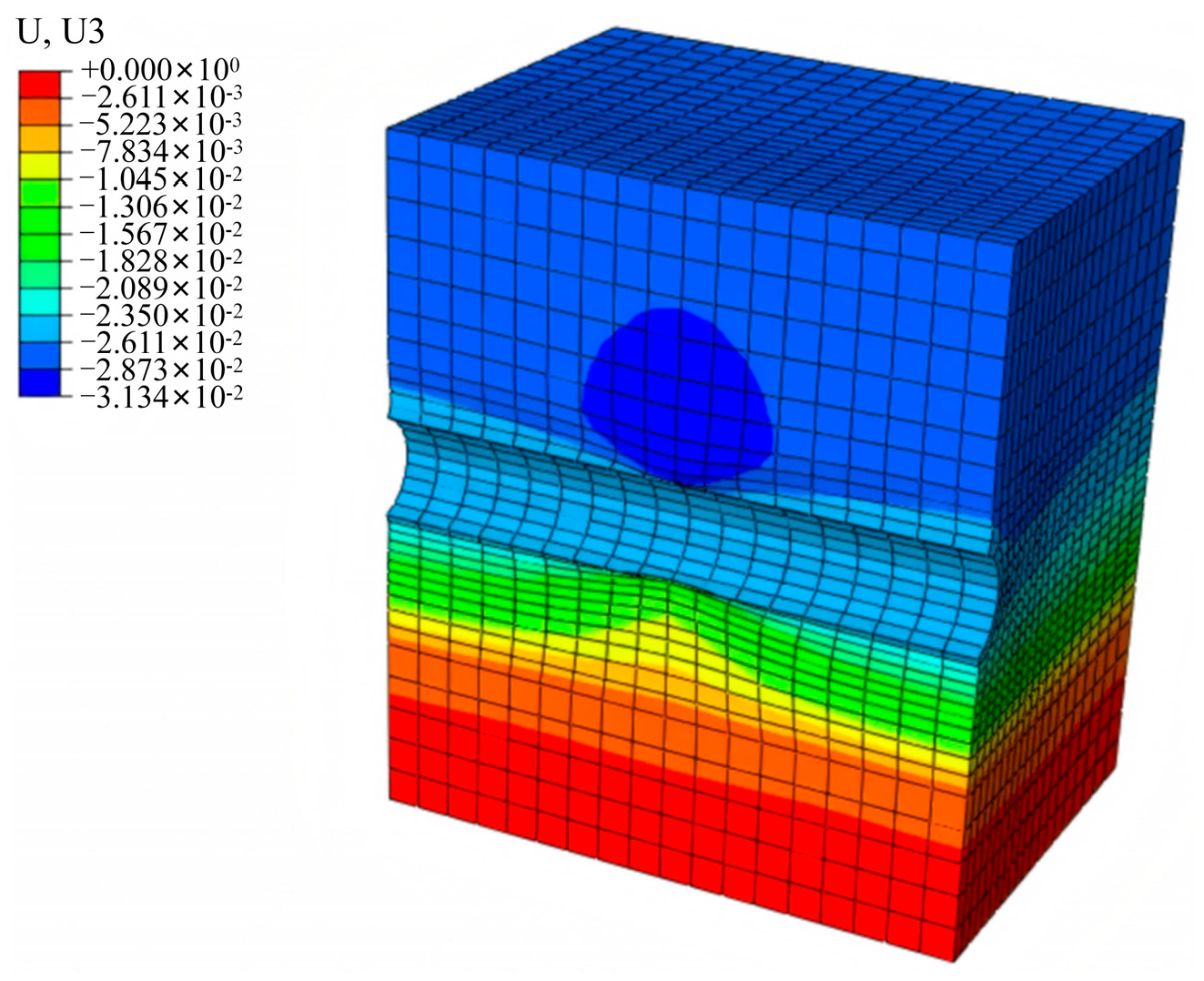
The numerical simulation results of soil settlement under the two working conditions of leakage at the joint of the segment and local leakage are shown in Figure 14 and Figure 15.
(1)
The evolution law of maximum surface subsidence over time
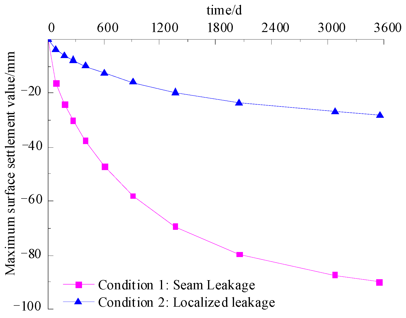
Based on the numerical simulation results, the maximum surface settlement value was extracted and the settlement time-history curve varying with time was plotted, as shown in Figure 16. As can be seen from Figure 16, the surface settlement rate under each seepage and leakage condition shows an evolution feature of “fast at first and then slow”, and the surface settlement gradually stabilizes over time. The final stable settlement values are as follows: 91 mm under the condition of joint leakage of the segment, and 32 mm under the condition of local leakage.
According to the “Technical Specifications for Monitoring of Urban Rail Transit Engineering”, the control standard for surface settlement of shield tunnels in medium-soft to weak strata is 25 to 35 mm. It can be seen that the settlement value under the joint leakage condition has significantly exceeded the control limit of the specification. Therefore, when leakage occurs in the lining structure of a shield tunnel, measures such as grouting and sealing should be taken promptly for treatment to effectively suppress the development of surface settlement and segment deformation.
(2)
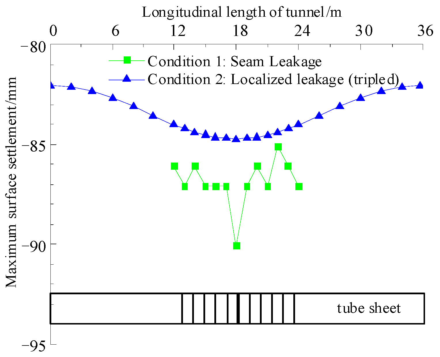
Spatial distribution characteristics of the maximum surface settlement value
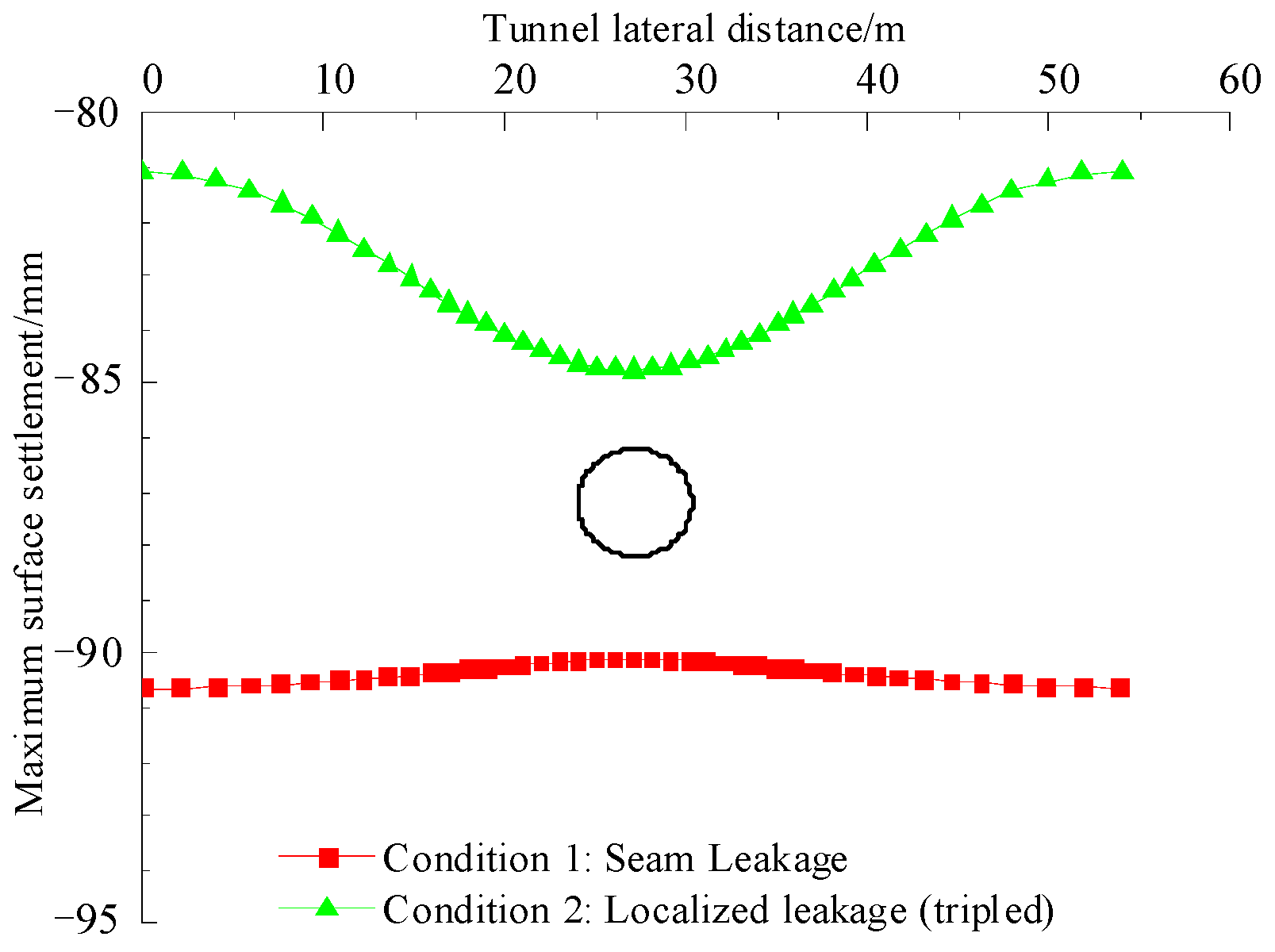
Based on the simulation results, the distribution of surface settlement along the transverse and longitudinal directions of the tunnel was extracted, respectively, and the variation curves were plotted as shown in Figure 17 and Figure 18. As can be seen from Figure 17 and Figure 18, under the condition of leakage at the joint of the segment, significant settlement occurs in the soil directly above the ground surface. The overall settlement curve is relatively smooth with small fluctuations, reflecting that the distribution of the affected area of the leakage is relatively uniform. In contrast, the settlement value caused by local seepage and leakage conditions is slightly lower, but the surface settlement curve presents a “groove” shape both horizontally and vertically.
This phenomenon can be explained by the seepage–softening mechanism: the leakage increases the local pore water pressure and reduces the effective stress of the surrounding soil, leading to softening and plastic deformation of the soil above the leakage zone. As a result, the settlement is concentrated in the central leakage area and gradually decreases outward, forming a groove-like distribution pattern. This indicates that the groove-shaped settlement profile is a manifestation of the localized effect of seepage-induced softening and strength attenuation in the soil [47,48].
Comprehensive analysis shows that the leakage at the joint of the segment has a more significant impact on surface settlement. It must be given priority attention and repaired in a timely manner to ensure the safety and stability of the tunnel structure and the surrounding environment.

5.3. The Influence of Different Seepage and Leakage Conditions on the Deformation of Tunnel Lining Structures

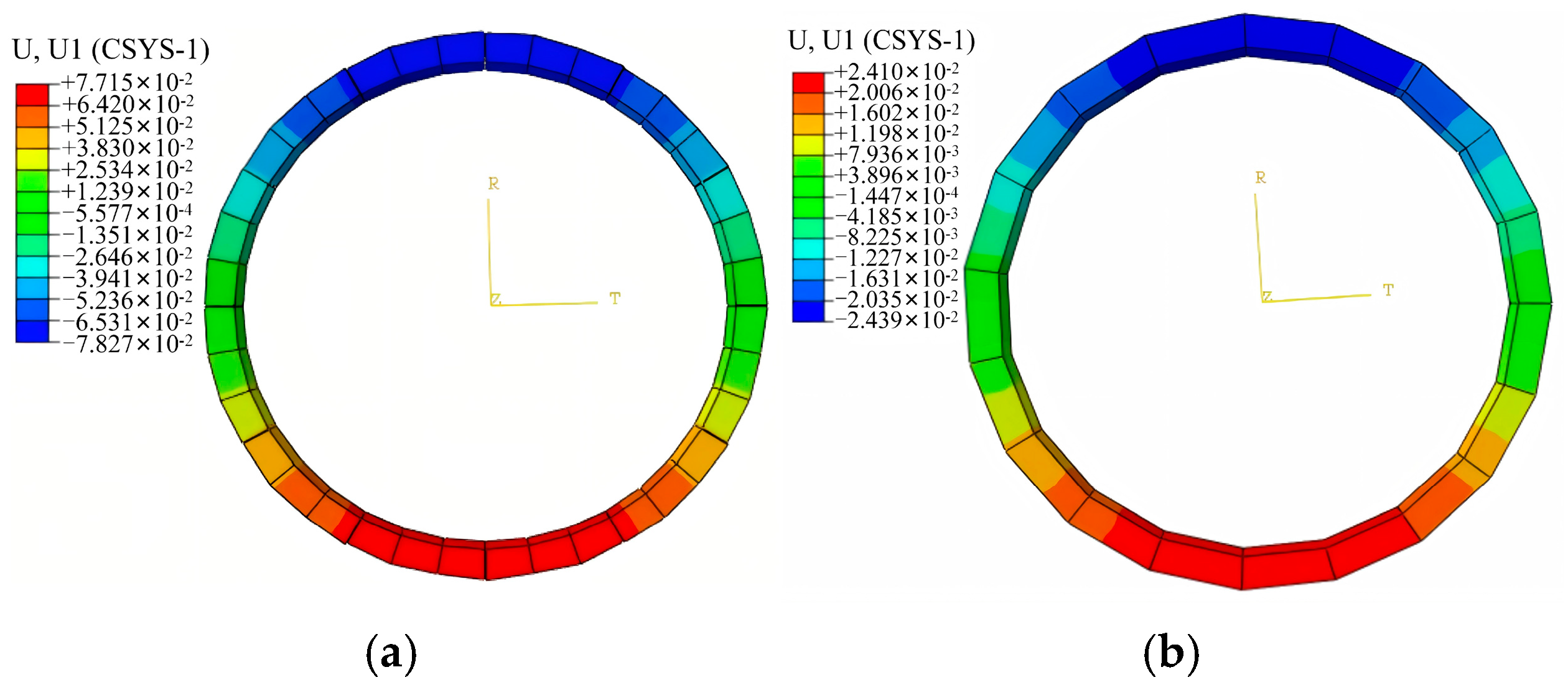
The displacement and deformation values of the tunnel were obtained through numerical simulation and projected onto a local polar coordinate system to obtain the distribution of displacement and deformation of the tunnel lining structure under different seepage and leakage conditions, as shown in Figure 19.
As can be seen from Figure 19, the deformation of the tunnel lining structure in the up-down direction is significantly greater than that in the left-right direction, and both the upper and lower segments show a displacement trend towards the deeper part of the stratum. In contrast, the overall deformation degree caused by the leakage at the joint of the segment is significantly higher than that caused by the local leakage. In addition, in the case of local leakage, obvious segment misalignment can be observed, suggesting its adverse effect on the continuity of the lining structure [49].
(1)
Comparison of tunnel displacement and deformation values under different seepage and leakage conditions
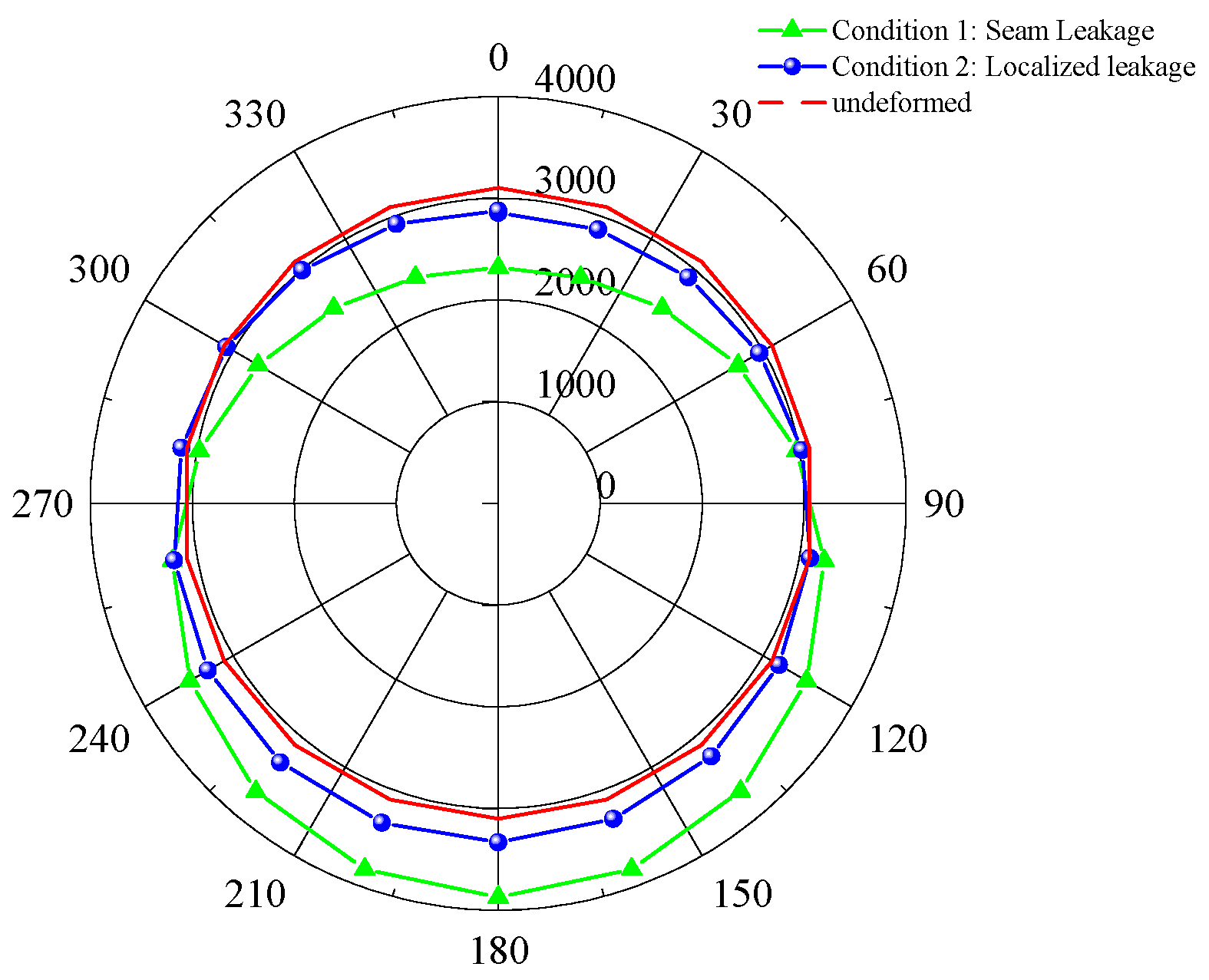
Based on the numerical simulation results, the comparison curves of tunnel displacement and deformation values under different seepage and leakage conditions were plotted, as shown in Figure 20.
As can be seen from Figure 20, the displacement and deformation values of the tunnel caused by leakage at the joint of the segment are much higher than those of local leakage, with specific values of 78.26 mm and 24.38 mm, respectively. According to the “Technical Specifications for Monitoring of Urban Rail Transit Engineering”, for shield tunnels in medium-soft and weak soil layers, the vertical displacement control standard for the lining structure is 20–30 mm, and the structural clearance convergence should be controlled within 0.2%D (i.e., 12.80 mm). Obviously, all the deformation values obtained in this study have exceeded the control standard, indicating that once joint or local leakage occurs, effective leak-stopping and structural reinforcement measures must be taken immediately to prevent further damage to the tunnel structure [50].
(2)
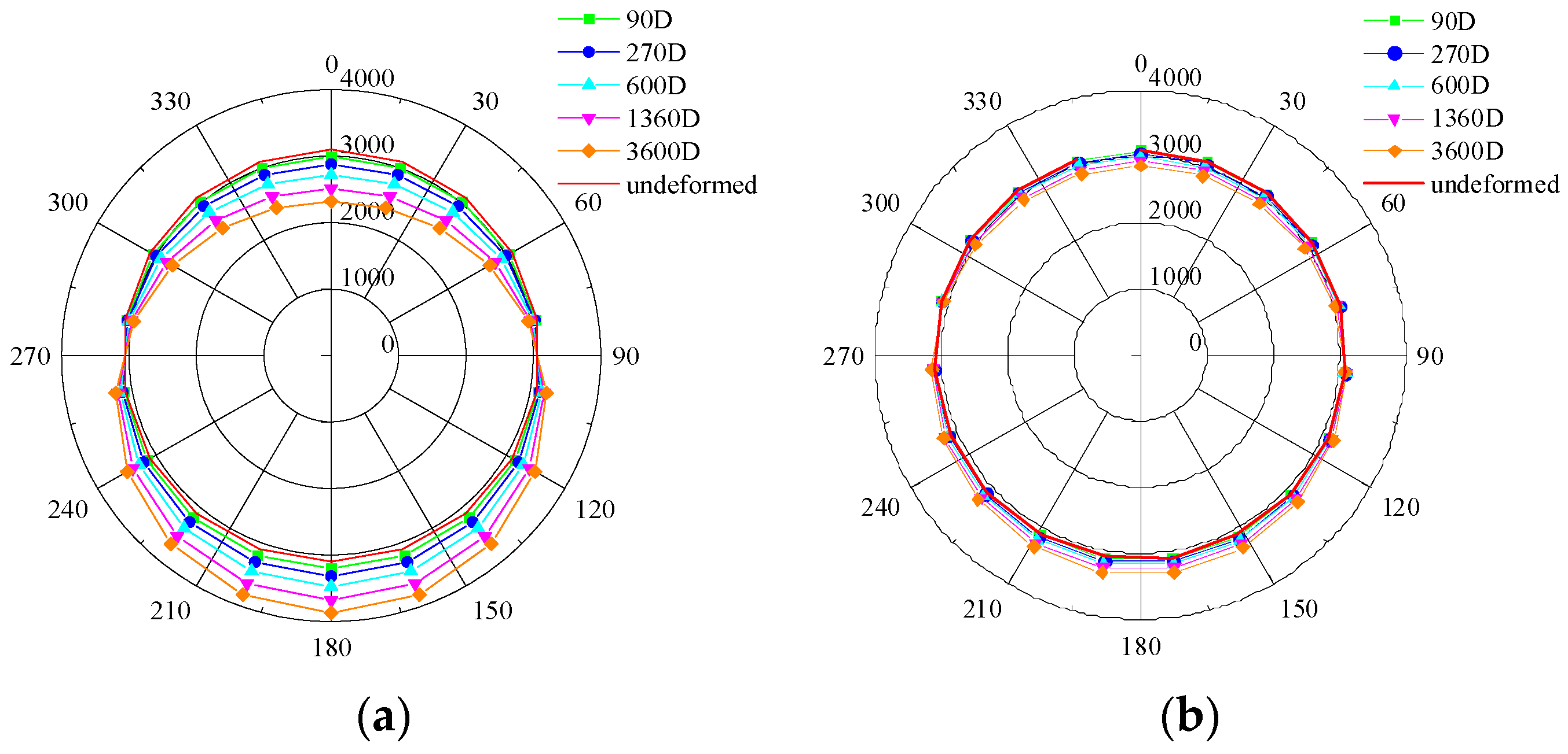
The variation law of tunnel displacement and deformation with time under different seepage and leakage conditions
Based on the numerical simulation results of seepage and leakage in shield tunnels under different working conditions, the displacement and deformation values of the tunnel lining structure over time were extracted, and the variation curves with time under different leakage conditions were plotted, as shown in Figure 21. The results in Figure 21 show that the displacement and deformation of the tunnel lining structure accumulate continuously with the increase in the duration of seepage and leakage. The initial growth rate is relatively large, and it gradually stabilizes in the later stage. Both forms of seepage and leakage are manifested as the displacement trend of the structure along the deep part of the stratum. As the leakage time extends, the increase in deformation of the lining structure gradually slows down, but the deformation trend has not completely stopped, suggesting that this process has a continuous cumulative risk.
The above findings have important implications for tunnel safety and maintenance practices. Excessive deformation caused by segment joint leakage represents a cumulative structural risk and should prompt enhanced monitoring and early-warning strategies. Emergency repair and leak-stopping measures should prioritize areas with joint leakage to prevent further damage. Moreover, the observed displacement evolution patterns provide valuable guidance for optimizing long-term tunnel health monitoring systems and can inform design and maintenance standards for shield tunnels beyond the Chinese codes.

6. Conclusions

In this study, the effects of leakage in shield tunnels located in water-rich silty clay strata were investigated through on-site monitoring and finite element simulations. The evolution of pore water pressure, surface settlement, and tunnel lining deformation under two typical working conditions—leakage at segment joints and local segment leakage—was analyzed. The main conclusions are as follows:
(1)
Leakage at segment joints and local segment leakage both lead to a significant decrease in pore water pressure in the surrounding soil, with the effect weakening as the distance from the leakage source increases. The influence of joint leakage is more pronounced than local leakage, highlighting the dominant role of segment joints in tunnel hydraulic response.
(2)
Surface settlement exhibits a “fast initial and then slow” development trend. Joint leakage results in a higher maximum settlement (91 mm), exceeding regulatory control standards, whereas local leakage leads to smaller settlement (32 mm), with a localized “groove-shaped” distribution above the leakage point. This indicates that seepage softening and local stress redistribution are key mechanisms controlling surface settlement.
(3)
Vertical deformation of the lining structure is greater than horizontal deformation, and both forms of leakage induce downward displacement trends toward deeper strata. The maximum lining displacements caused by joint leakage and local leakage are 78.26 mm and 24.38 mm, respectively, both exceeding design control standards. Segment misalignment under local leakage suggests adverse effects on structural continuity, emphasizing the importance of prompt monitoring and reinforcement.
(4)
The results indicate that segment joints should be prioritized for monitoring and emergency repair, while localized leakage areas also require timely inspection and remedial measures. The findings provide a theoretical reference for tunnel maintenance, emergency response prioritization, and design optimization beyond existing code requirements.
(5)
This study is based on a simplified 3D model and assumes uniform leakage at joints and segments. Results are primarily applicable to water-rich silty clay strata and may differ under other geological conditions. Future research should explore different soil types, long-term monitoring strategies, coupled seepage–structure interactions, and probabilistic approaches to improve tunnel safety assessment and maintenance planning.

Author Contributions

Conceptualization, X.T. and Y.M.; methodology, X.T. and Y.M.; software, X.T. and F.H.; validation, J.T.; formal analysis, X.T. and F.H.; investigation, F.H.; data curation, F.H. and J.T.; writing—original draft preparation, X.T.; writing—review and editing, X.T.; project administration, Y.M.; funding acquisition, Y.M. All authors have read and agreed to the published version of the manuscript.

Funding

Shaanxi Provincial Department of Education Local Service Special Scientific Research Program Project (22JC046); Shaanxi Provincial Key Research and Development Program (2020SF-373).

Data Availability Statement

Data will be made available on request.

Conflicts of Interest

Author Jinhua Tang was employed by the company Xi’an University of Architecture and Technology Engineering Co., Ltd. The authors declare that they have no known competing financial interests or personal relation-ships that could have appeared to influence the work reported in this paper.

References

  1. Xie, J.; Huang, X.; Jin, G.; Zhang, Z. Seepage characteristics and mechanical response of shield tunnels under localized leakage and exosmosis. Rock Soil Mech. 2023, 44, 1179–1189. [Google Scholar]
  2. Chen, F.; Sun, J.; Xiong, H.; Yin, Z.; Chen, X. Numerical implication of water–soil leakage induced by longitudinal tunnel segment dislocation opening in saturated strata. J. Rock Mech. Geotech. Eng. 2025; in press. [Google Scholar]
  3. Zhao, R.; Li, L.; Chen, X.; Zhang, S. Mechanical Response of Pipeline Leakage to Existing Tunnel Structures: Insights from Numerical Modeling. Buildings 2025, 15, 1771. [Google Scholar] [CrossRef]
  4. Macchiarulo, V.; Milillo, P.; DeJong, M.; Gonzalez Marti, J.; Sánchez, J.; Giardina, G. Integrated InSAR monitoring and structural assessment of tunnelling-induced building deformations. Struct. Control Health Monit. 2021, 28, e2781. [Google Scholar] [CrossRef]
  5. Afshani, A.; Li, W.; Oka, S.; Itoh, Y.; Akagi, H. Study of the long-term behavior of segmented tunnels in cohesive soil based on the circumferential joint opening. Tunn. Undergr. Space Technol. 2022, 120, 104210. [Google Scholar] [CrossRef]
  6. Banerjee, S.; Sikdar, P. Land Subsidence due to leakage of aquitard-aquifer pore water in an under-construction tunnel of East-West Metro Railway Project, Kolkata. J. Geol. Soc. India 2020, 96, 467–474. [Google Scholar] [CrossRef]
  7. Wang, L.; Niu, X.; Zhao, Y.; Li, W.; Song, W.; Zhang, C. Study on the mechanism and rapid treatment method of leakage disease at the junction between the shaft and shield tunnel. Eng. Fail. Anal. 2023, 154, 107639. [Google Scholar] [CrossRef]
  8. Guo, H.; Wang, Y.; Niu, X. Research on the Application of Backwall Grouting in Leakage Treatment of Operating Tunnels. E3S Web Conf. 2023, 439, 02011. [Google Scholar] [CrossRef]
  9. Shen, J.; Zhang, H.; Wan, L.; Zhang, C.; Shao, X.; Lin, Z.; Song, J. Causes of tunnel diseases in a karst stratum and remediation measures: A case study. Front. Earth Sci. 2022, 10, 882058. [Google Scholar] [CrossRef]
  10. Lin, C.; Wang, X.; Li, Y.; Zhang, F.; Xu, Z.; Du, Y. Forward modelling and GPR imaging in leakage detection and grouting evaluation in tunnel lining. KSCE J. Civ. Eng. 2020, 24, 278–294. [Google Scholar] [CrossRef]
  11. Jiang, J.; Shen, Y.; Wang, J.; Zang, Y.; Wu, W.; Wang, J.; Zang, Y.; Wu, W.; Wang, J.; Li, J.; et al. Boosted bagging: A hybrid ensemble deep learning framework for point cloud semantic segmentation of shield tunnel leakage. Tunn. Undergr. Space Technol. 2025, 164, 106842. [Google Scholar] [CrossRef]
  12. Wang, Y.; Huang, K.; Sun, L.; Gao, J.; Guo, Z.; Chen, X. WLAN: Water Leakage-Aware Network for water leakage identification in metro tunnels. Neural Comput. Appl. 2025, 37, 22179–22189. [Google Scholar] [CrossRef]
  13. Wang, W.; Xu, X.; Yang, H. Intelligent detection of tunnel leakage based on improved mask R-CNN. Symmetry 2024, 16, 709. [Google Scholar] [CrossRef]
  14. Liu, Y.; Yang, J.; Yin, Z. Numerical analysis of the impact of internal erosion on underground structures: Application to tunnel leakage. Rock Soil Mech. 2022, 43, 8. [Google Scholar]
  15. Park, D. Numerical investigation on the effect of water leakage on the ground surface settlement and tunnel stability. Tunn. Undergr. Space Technol. 2024, 146, 105656. [Google Scholar] [CrossRef]
  16. Shi, X.; Zheng, L.; Rong, C.; Cheng, H.; Cai, H.; Li, T. Study on the rules of ground settlement and pipeline deformation considering the combined effects of pipeline damage leakage and shield tunneling construction. Transp. Geotech. 2024, 49, 101367. [Google Scholar] [CrossRef]
  17. Mu, W.; Li, L.; Chen, D.; Wang, S.; Xiao, F. Long-term deformation and control structure of rheological tunnels based on numerical simulation and on-site monitoring. Eng. Fail. Anal. 2020, 118, 104928. [Google Scholar] [CrossRef]
  18. Gong, C.; Cheng, M.; Ge, Y.; Song, J.; Zhou, Z. Leakage mechanisms of an operational underwater shield tunnel and countermeasures: A case study. Tunn. Undergr. Space Technol. 2024, 152, 105892. [Google Scholar] [CrossRef]
  19. Zhang, Z.; Mao, M.; Pan, Y.; Zhang, M.; Ma, S.; Cheng, Z.; Wu, Z. Experimental study for joint leakage process of tunnel lining and particle flow numerical simulation. Eng. Fail. Anal. 2022, 138, 106348. [Google Scholar] [CrossRef]
  20. Chen, S.; Yang, Z.; Liu, S.; Li, L.; Zheng, Y.; Yuan, Y. Numerical simulation and analysis of crack disease in tunnel lining structure. Front. Mater. 2022, 9, 1007855. [Google Scholar] [CrossRef]
  21. Martínez, R.; Schroeder, F.; Potts, D. Numerical study of long-term settlement following twin tunnel construction. Obras Proy. 2015, 17, 23–29. [Google Scholar] [CrossRef]
  22. Lu, X.; Wang, H.; Huang, M. Upper bound solution for the face stability of shield tunnel below the water table. Math. Probl. Eng. 2014, 2014, 727964. [Google Scholar] [CrossRef]
  23. Miranda, P.; Vargas Jr, E.A.; Moraes, A. Evaluation of the Modified Cam Clay model in basin and petroleum system modeling (BPSM) loading conditions. Mar. Pet. Geol. 2020, 112, 104112. [Google Scholar] [CrossRef]
  24. Wang, F.; Shao, J.; Li, W.; Wang, L.; Wang, Y.; Liu, H. Numerical simulation study on lining damage of shield tunnel under train load. Sustainability 2022, 14, 14018. [Google Scholar] [CrossRef]
  25. Shi, L.; Wang, D.; Zhang, Y.; Han, F.; Lyu, Q. An analytical solution for internal forces of shallow circular low-to-vacuum tunnel linings in soft soils. Sci. Rep. 2024, 14, 31436. [Google Scholar] [CrossRef] [PubMed]
  26. Kou, L.; Xiong, Z.; Cui, H.; Zhao, J. Study on mechanical characteristics of segmental joints of a large-diameter shield tunnel under ultrahigh water pressure. Sensors 2021, 21, 8392. [Google Scholar] [CrossRef]
  27. Kavvadas, M.; Litsas, D.; Vazaios, I.; Fortsakis, P. Development of a 3D finite element model for shield EPB tunnelling. Tunn. Undergr. Space Technol. 2017, 65, 22–34. [Google Scholar] [CrossRef]
  28. Zhang, W.; De Corte, W.; Liu, X.; Taerwe, L. Influence of rotational stiffness modeling on the joint behavior of quasi-rectangular shield tunnel linings. Appl. Sci. 2020, 10, 8396. [Google Scholar] [CrossRef]
  29. Liu, D.; Wang, F.; Hu, Q.; Huang, H.; Zuo, J.; Tian, C.; Zhang, D. Structural responses and treatments of shield tunnel due to leakage: A case study. Tunn. Undergr. Space Technol. 2020, 103, 103471. [Google Scholar] [CrossRef]
  30. Mei, Y.; Luo, Z.; Jiang, H.; Gong, H.; Hou, Y.; Wang, X. Study on the floating law of metro segments in water-rich sandy silt and silty clay strata. KSCE J. Civ. Eng. 2022, 26, 2979–2991. [Google Scholar] [CrossRef]
  31. Yu, J.; Sun, M.; He, S.; Huang, X.; Wu, X.; Liu, L. Accumulative deformation characteristics and microstructure of saturated soft clay under cross-river subway loading. Materials 2021, 14, 537. [Google Scholar] [CrossRef]
  32. Li, Y.; Mu, L.; Cao, J. Impact of Seepage on the Underground Water Level in a Complex Soil-Water-Structure System. Adv. Civ. Eng. 2022, 2022, 7034778. [Google Scholar] [CrossRef]
  33. Zheng, G.; Lei, Y.; Cui, T.; Cheng, X.; Diao, Y.; Zhang, T.; Sun, J. Experimental research on the transverse effective bending rigidity of shield tunnels. Adv. Civ. Eng. 2019, 2019, 2174562. [Google Scholar] [CrossRef]
  34. Zheng, G.; Sun, J.; Zhang, T.; Zhang, X.; Li, X.; Cheng, H.; Diao, Y. Numerical study on the impact of local failure on adjacent structures in a shield tunnel. Acta Geotech. 2023, 18, 2155–2168. [Google Scholar] [CrossRef]
  35. Huang, Z.; Zhang, C.; Ma, S.; Zhang, J.; Zhu, Q. Study of the mechanical behaviour and damage characteristics of three new types of joints for fabricated rectangular tunnels using a numerical approach. Tunn. Undergr. Space Technol. 2021, 118, 104184. [Google Scholar] [CrossRef]
  36. Lan, X.; Zhang, X.; Yin, Z.; Li, X.; Yang, T. Mitigation of karst tunnel water inrush during operation in seasonal variation zone: Case study in Nanshibi Tunnel. J. Perform. Constr. Facil. 2021, 35, 04021010. [Google Scholar] [CrossRef]
  37. Xu, S.; Zhang, X.; Wang, L.; Yue, C.; Chen, X.; Luo, Z.; Fu, L. Study on the Mechanism of Water and Sand Leakage in a Foundation Pit Retaining Structure Based on the Computational Fluid Dynamics–Discrete Element Method. Buildings 2024, 14, 724. [Google Scholar] [CrossRef]
  38. Gong, C.; Ding, W. A computational framework to predict the water-leakage pressure of segmental joints in underwater shield tunnels using an advanced finite element method. Int. J. Numer. Anal. Methods Geomech. 2018, 42, 1957–1975. [Google Scholar] [CrossRef]
  39. Li, S.; Liu, H.; Li, L.; Zhang, Q.; Wang, K.; Wang, K. Large scale three-dimensional seepage analysis model test and numerical simulation research on undersea tunnel. Appl. Ocean Res. 2016, 59, 510–520. [Google Scholar] [CrossRef]
  40. Liu, Y.; Wang, Z.; Liu, X.; Han, J. Study on leakage assessment and stability analysis of water level changes in tunnels near reservoirs. Water 2024, 16, 2378. [Google Scholar] [CrossRef]
  41. Huang, L.; Ma, J.; Lei, M.; Liu, L.; Lin, Y.; Zhang, Z. Soil-water inrush induced shield tunnel lining damage and its stabilization: A case study. Tunn. Undergr. Space Technol. 2020, 97, 103290. [Google Scholar] [CrossRef]
  42. Xu, S.; Ma, E.; Lai, J.; Yang, Y.; Liu, H.; Yang, C.; Hu, Q. Diseases failures characteristics and countermeasures of expressway tunnel of water-rich strata: A case study. Eng. Fail. Anal. 2022, 134, 106056. [Google Scholar] [CrossRef]
  43. Cui, X.; Li, P.; Wang, C.; Ge, Z.; Li, S.; Di, Q. Effect of seepage flow on face stability for a tunnel in water-rich silty clay overlying sandy cobble strata. Tunn. Undergr. Space Technol. 2025, 161, 106539. [Google Scholar] [CrossRef]
  44. Zhang, D.; Ma, L.; Zhang, J.; Hicher, P.; Juang, C. Ground and tunnel responses induced by partial leakage in saturated clay with anisotropic permeability. Eng. Geol. 2015, 189, 104–115. [Google Scholar] [CrossRef]
  45. Huang, Z.; Cheng, Y.; Zhang, D.; Yan, D.; Shen, Y. Seismic fragility and resilience assessment of shallowly buried large-section underground civil defense structure in soft soils: Framework and application. Tunn. Undergr. Space Technol. 2024, 146, 105640. [Google Scholar] [CrossRef]
  46. Shin, J.; Addenbrooke, T.; Potts, D. A numerical study of the effect of groundwater movement on long-term tunnel behaviour. Geotechnique 2002, 52, 391–403. [Google Scholar] [CrossRef]
  47. Wang, X.; Wang, B.; Yuan, Y.; Yang, T.; Dong, G.; Shi, C. Study on the Effect of EICP Combined with Nano-SiO2 and Soil Stabilizer on Improving Loess Surface Strength. Buildings 2025, 15, 1998. [Google Scholar] [CrossRef]
  48. Wang, X.; Chen, C. Vibration Table Test of Prefabricated L-Shaped Column Concrete Structure. Buildings 2025, 15, 2329. [Google Scholar] [CrossRef]
  49. Shijie, Z.; Guyi, Z.; Deming, L.; Shuyi, W.; Chao, W. The crucial techniques of water leakage treatment in operating highway tunnel. IOP Conf. Ser. Earth Environ. Sci. 2020, 525, 012160. [Google Scholar] [CrossRef]
  50. Zhang, D.; Liu, J.; Huang, Z.; Yang, G.; Jiang, Y.; Jia, K. Waterproof performance of tunnel segmental joints under different deformation conditions. Tunn. Undergr. Space Technol. 2022, 123, 104437. [Google Scholar] [CrossRef]
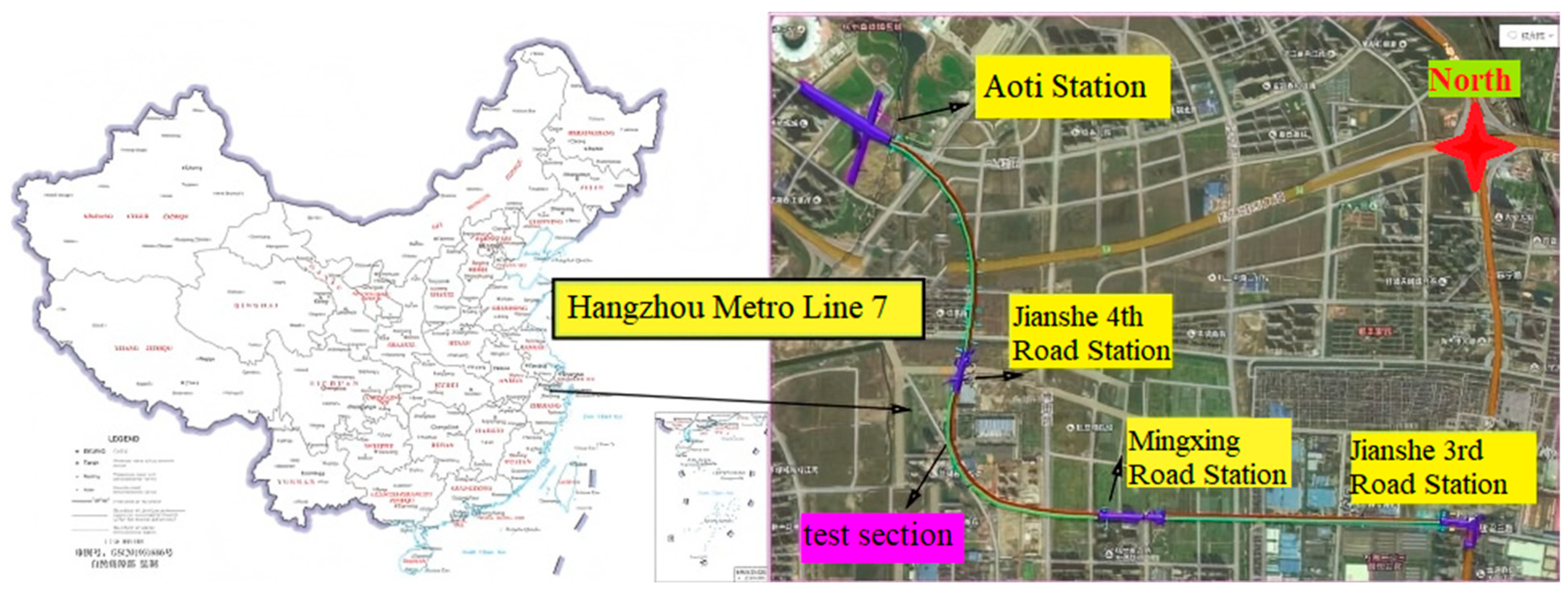
Figure 1. Plan view of the test site.
Buildings 15 03867 g001
Figure 2. Cross-sectional view of the shield tunnel and surrounding stratum.
Buildings 15 03867 g002
Figure 3. Curve of segment damage rate variation.
Buildings 15 03867 g003
Figure 4. Distribution proportion of leakage locations in tunnel lining structure.
Buildings 15 03867 g004
Figure 5. Schematic diagram of tunnel segment joint water leakage model.
Buildings 15 03867 g005
Figure 6. Diagram of the local water leakage model for tunnel segments.
Buildings 15 03867 g006
Figure 7. Displacement monitoring of tunnel segments. (a) Schematic diagram of segment monitoring equipment layout; (b) Segment monitoring site.
Buildings 15 03867 g007
Figure 8. Comparison of measured and simulated ground settlement over 600 days.
Buildings 15 03867 g008
Figure 9. Comparison of measured and simulated pore water pressure distribution on day 600.
Buildings 15 03867 g009
Figure 10. Pore water pressure distribution under segment joint leakage (Pa).
Buildings 15 03867 g010
Figure 11. Pore water pressure distribution under local leakage (Pa).
Buildings 15 03867 g011
Figure 12. Variation in pore water pressure with soil depth under different leakage conditions.
Buildings 15 03867 g012
Figure 13. Variation curves of pore water pressure along tunnel longitudinal direction under different leakage condition.
Buildings 15 03867 g013
Figure 14. Soil settlement distribution considering segment joint leakage (Unit: mm).
Buildings 15 03867 g014
Figure 15. Soil settlement distribution considering segment local water leakage condition (Unit: mm).
Buildings 15 03867 g015
Figure 16. Time history curve of maximum surface settlement under different water leakage conditions.
Buildings 15 03867 g016
Figure 17. Lateral variation in surface settlement under different water leakage conditions.
Buildings 15 03867 g017
Figure 18. Longitudinal variation in surface settlement under different water leakage conditions.
Buildings 15 03867 g018
Figure 19. Displacement and deformation distribution of the tunnel under different water leakage conditions (Unit: mm). (a) Distribution of tunnel displacement and deformation considering segment joint leakage condition; (b) Distribution of tunnel displacement and deformation considering localized segment leakage.
Buildings 15 03867 g019
Figure 20. Comparison of tunnel displacement and deformation under different water leakage conditions.
Buildings 15 03867 g020
Figure 21. Tunnel displacement and deformation variation with time under different leakage conditions. (a) Tunnel displacement and deformation with time under segment joint leakage; (b) Tunnel displacement and deformation with time under local leakage.
Buildings 15 03867 g021
Table 1. Statistics of segment leakage conditions.
Serial NumberLeakage Location
Leakage Occurs at the Joint of the SegmentThe Segment Is Damaged and LeakingThe Hole Cracked and LeakedOthers
Left line1411571439
Right line17014612611
Total31130326920
Table 2. Physical and mechanical parameters of strata.
Stratum NameElastic Modulus
(E/MPa)
Poisson’s Ratio
(μ)
Cohesion
(c/kPa)
Internal Friction
Angle (ψ/(°))
Heavy
γ (kN/m3)
Soft clay B1100.428.008.0017.00
Miscellaneous fill soil B2150.2212.5012.0019.00
Muddy clay B3200.3524.2020.4019.80
Silty clay B4250.3532.7019.0020.80
medium sand B5300.303.0034.0019.47
Sandy soil B6350.323.0035.0020.00
Table 3. Main assumptions and limitations of the numerical simulation.
AspectAssumptionLimitation/Applicability
Soil behaviorThe soil follows the Mohr–Coulomb elastic–plastic model.Time-dependent and creep effects are not considered.
Groundwater conditionsSteady-state seepage field is assumed before leakage initiation.Transient flow effects during early leakage are simplified.
Leakage representationLeakage is modeled as local permeability enhancement at segment joints.Real crack networks are simplified to uniform leakage zones.
Boundary conditionsThe lateral boundaries are fixed horizontally, and the bottom boundary vertically.Possible boundary influence near model edges is neglected.
Material parametersMaterial properties are homogeneous within each soil layer.Soil variability and anisotropy are not fully captured.
Interface behaviorSegment–soil contact is simulated with a friction coefficient of 0.4.Micro-scale roughness and local detachment are simplified.
Disclaimer/Publisher’s Note: The statements, opinions and data contained in all publications are solely those of the individual author(s) and contributor(s) and not of MDPI and/or the editor(s). MDPI and/or the editor(s) disclaim responsibility for any injury to people or property resulting from any ideas, methods, instructions or products referred to in the content.