1. Introduction
The global expansion of transportation infrastructure has intensified the demand for long tunnels that traverse complex geological conditions. Vertical shafts are indispensable components of these tunnel systems, fulfilling critical functions such as ventilation, emergency access, and muck removal. Ensuring their structural stability is particularly important in karst formations containing multiple cavities, which disrupt the in situ stress field and increase the risk of geological hazards.
Common vertical shaft excavation techniques include down-reaming, climbing–bucket sinking, reverse blasting, and the Raise Boring Machine (RBM) method [
1,
2,
3]. Among these, the RBM method has gained widespread attention for its safety, efficiency, and minimal environmental disruption. Its applicability has been validated in various engineering projects, both in China [
4,
5,
6,
7,
8,
9] and internationally, such as in Japan [
10], Europe [
11,
12], and Germany [
13], with comparative models and selection methods also explored [
14].
Recent comparative studies have shown that the RBM method provides significant advantages over conventional drilling and blasting techniques in terms of safety, efficiency, and environmental impact. For example, Cheng et al. [
6] reported that the use of RBM reduced construction-related accidents by over 35% compared to traditional methods. Li et al. [
8] demonstrated that construction time was reduced by approximately 30%, and cost savings of up to 20% were achieved due to reduced labor requirements and simplified ventilation needs. Additionally, the RBM process generates less vibration and noise, making it more suitable for densely fractured or sensitive geological environments. These advantages support the adoption of RBM in complex karst terrains, such as the one investigated in this study.
To better understand shaft behavior under excavation, numerical methods such as FEM, DEM, and DEM–FEM coupling have been widely adopted [
15,
16,
17,
18,
19,
20,
21,
22]. Domestic studies have also demonstrated their practical use in ventilation shaft simulations and construction optimization [
19,
20,
21,
22,
23]. Additionally, hybrid modeling techniques, such as CZM, THM, and seepage–stress coupling frameworks, have expanded the capacity to simulate jointed or fractured rock responses under complex loads [
24,
25,
26,
27,
28,
29].
Given the complexity of karst geology and the limitations of current numerical methods, it is not feasible to reproduce all possible cavity distributions and field uncertainties in a single model. Therefore, representative assumptions and the use of established constitutive models are widely adopted. Previous studies have confirmed the validity of this approach. Saadati et al. developed constitutive models for brittle rock under dynamic loading [
30]; Hu et al., Sun et al., and Li et al. examined the effects of drilling parameters, tool profiles, and boring rates on rock-breaking efficiency through combined numerical and experimental studies [
31,
32,
33]; Liu and Meng summarized key raise boring technologies [
34]; Guo et al. proposed shaft stability evaluation methods in coal mines [
35]; and Han et al. investigated piles in karst strata with cavities using FEM [
36]. These works demonstrate that simplified yet representative simulations are both reasonable and reliable.
Despite these advances, the application of RBM in deep karst terrains with multiple irregular cavities remains underexplored. Several researchers have recently addressed shaft behavior in karst environments using advanced modeling approaches [
37,
38], but gaps remain regarding interaction mechanisms and failure thresholds. This study integrates field monitoring and finite element simulation to evaluate excavation stability in such formations, aiming to enhance theoretical guidance for shaft construction under complex geologies.
2. Project Overview
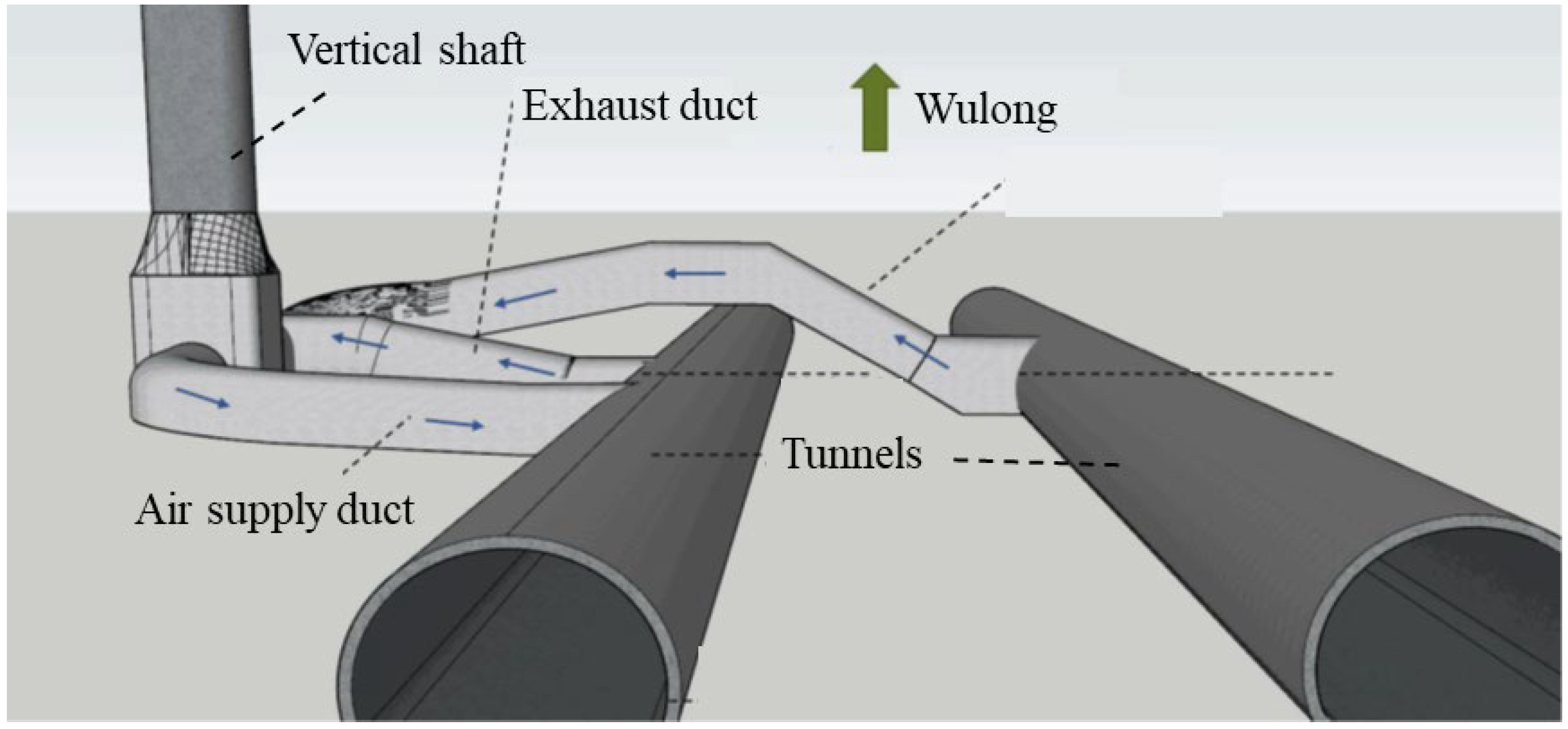
In order to investigate the raise boring method for shaft excavation under multi-cavity karst geological conditions, it was essential to select a site characterized by the presence of numerous karst cavities. Therefore, the Zimuyan Tunnel was chosen as the case study for numerical simulation. The Zimuyan Tunnel is a key section of the Wulong–Daozhen Expressway, located at the junction of Chongqing and Guizhou provinces, China. A deep vertical ventilation shaft with a total depth of 428.2 m and a diameter of 6.4 m was constructed on the right tunnel alignment to ensure proper airflow and access. Due to the significant depth and anticipated geological challenges, the RBM method was selected over traditional excavation techniques to improve safety and efficiency (
Figure 1).
The stratigraphy exposed along the shaft alignment consists of the following formations:
Quaternary Residual and Slope-Deposited Clay (Q4 ₑₗ₊d ₗ): Primarily distributed near the ground surface, with a thickness ranging from 0 to 0.5 m.
Upper Permian Wujiaping–Changxing Formation (P2w–c): Composed mainly of limestone interbedded with argillaceous (mud-rich) bands. In certain sections, thin interlayers of limestone with mudstone and mudstone with limestone are present. At the bottom of this formation, carbonaceous mudstone and coal seams are observed. This formation extends from the surface to a depth of approximately 165 m.
Lower Permian Maokou Formation Limestone (P1m): This unit is encountered from a depth of 165 m down to the bottom of the shaft.
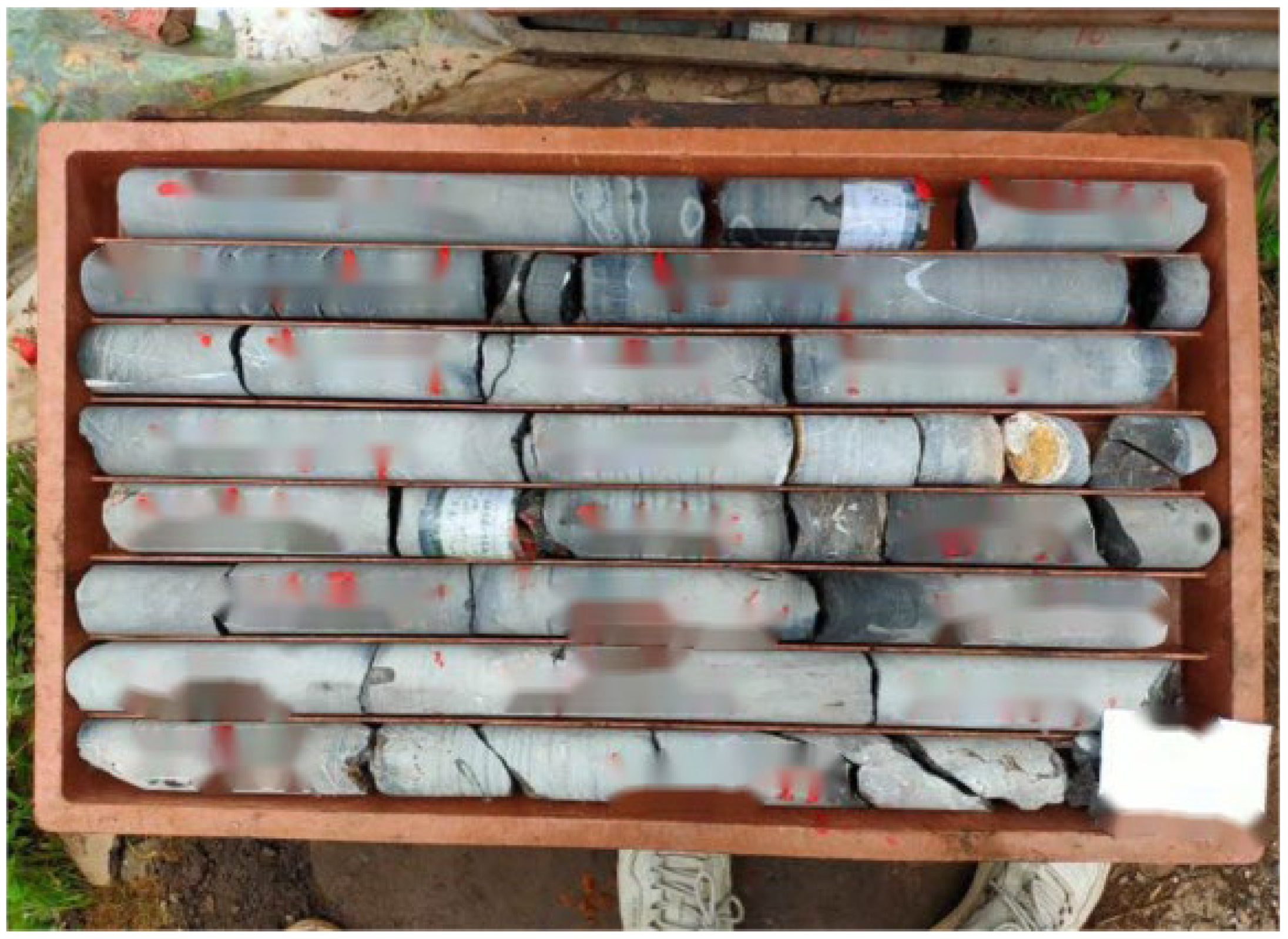
The lithology and structural features of these formations were confirmed through core samples obtained from borehole drilling along the shaft alignment, as shown in
Figure 2.
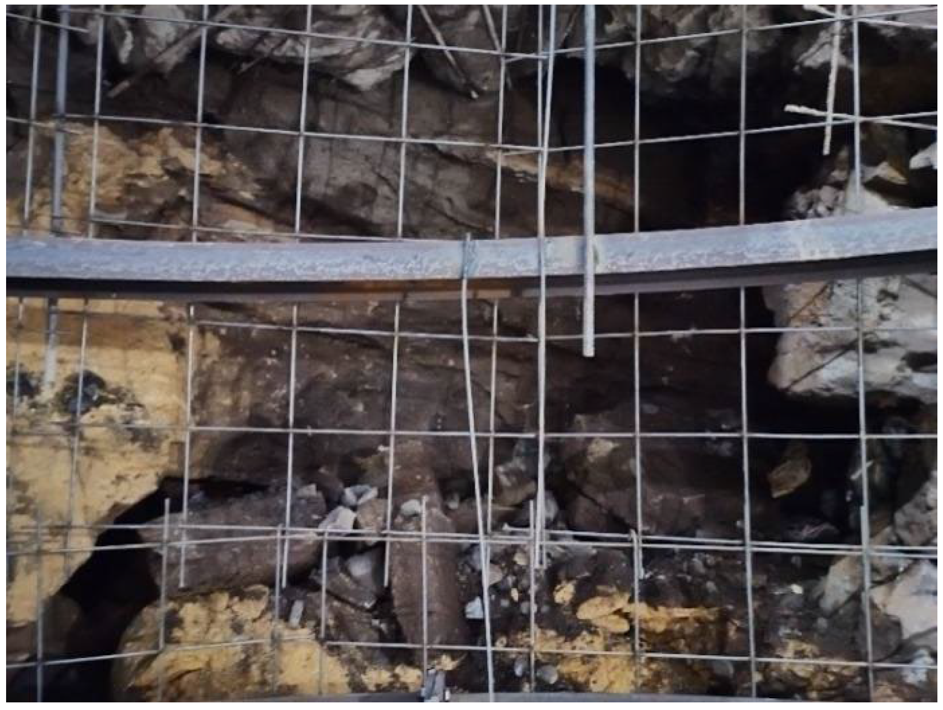
Borehole data revealed that karst fractures are relatively well-developed at depths between 300 and 450 m. Comprehensive geological analysis indicates that the karst features in the vicinity of the shaft are highly developed, and there is a significant likelihood of encountering concealed karst cavities during excavation. This presents a high level of engineering risk. The exposure of karst cavities during excavation may lead to serious geological hazards such as water inrush, mud inflow, and roof collapse, as shown in
Figure 3.
3. Finite Element Analysis
3.1. Numerical Model and Mesh
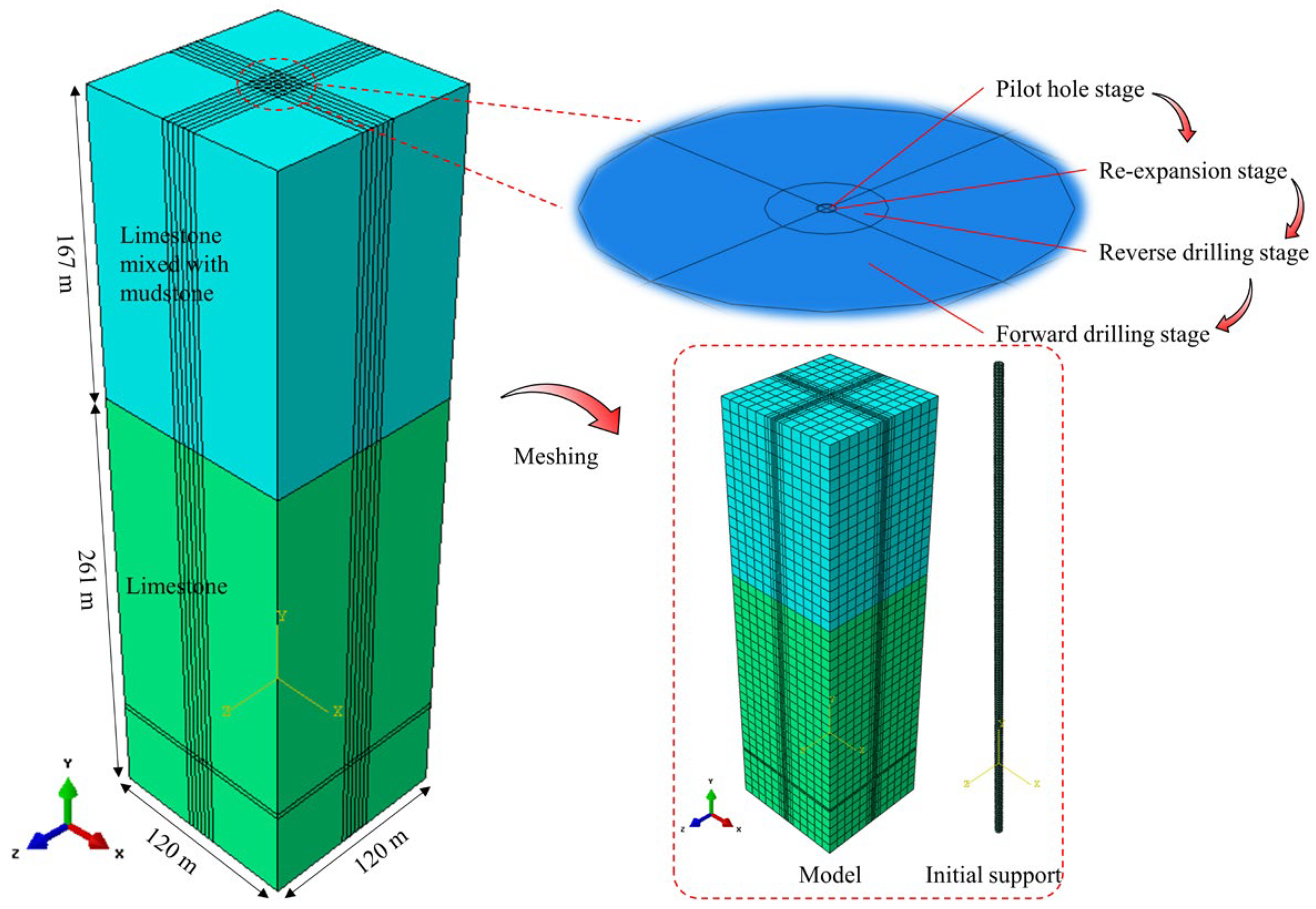
To analyze the influence of multiple karst cavities on the stability of surrounding rock during the excavation of a deep and large-diameter vertical shaft, a three-dimensional finite element model was established using the ABAQUS software (version 6.14). The dimensions of the 3D model are 120 m × 120 m × 428 m (length × width × height).
Based on the results of detailed geological investigations conducted on site, a corresponding geometric model was established. According to the borehole data, the geological profile along the shaft alignment consists of limestone interbedded with mudstone from 0 to 167 m, and transitions to massive limestone from 167 m to the bottom depth of 428 m. The RBM construction process was modeled in the following sequential stages: pilot hole drilling, reaming, forward drilling and reverse drilling. To ensure the generation of a high-quality and regular mesh, the circular excavation area at the center of the shaft was first discretized. This was followed by meshing of the entire model domain based on the initial subdivision, thereby improving element uniformity and computational stability. A total of 41,974 elements and 47,520 nodes were generated in the model. The 3D geometry and mesh layout of the model are shown in
Figure 4 [
39].
Although natural karst voids are often irregular, this geometric abstraction allows for clearer analysis of positional influence while controlling variables. Similarly, groundwater effects and cavity fillings were excluded from the model to focus on mechanical responses. For simplification, the rock strata were assumed to be horizontally layered and homogeneous, and the effects of groundwater and filling materials were neglected. If groundwater effects are taken into account, the stability of the surrounding rock during raise boring excavation would be reduced.
In the numerical model, the rock mass was simulated using C3D8R solid elements, while the initial support structures were modeled with shell elements. Horizontal constraints were applied to all lateral boundaries of the model, vertical and horizontal constraints were imposed at the bottom boundary, and the top boundary was left free [
39]. To ensure the feasibility of large-scale simulations, certain simplifications were introduced. The karst cavities were idealized as square voids with a fixed size of 0.5D, based on average field measurements. It is acknowledged that groundwater could significantly influence excavation-induced stress and deformation, and this will be considered in future refined models [
40,
41,
42,
43,
44].
Given that the model dimensions are 18.75 times the shaft diameter, boundary effects on the simulation results can be considered negligible [
45]. According to drilling data, karst features are typically highly irregular in geometry; therefore, the cavity was simplified as a square in this study. The side length of the square cavity was set to 0.5D (where D is the shaft diameter), and the minimum distance between the cavity and the shaft was also defined as 0.5D. The influence of groundwater and other cavity fillings was not considered. Horizontal constraints were applied to all lateral boundaries of the model, while both horizontal and vertical constraints were imposed at the base. The top surface of the model was defined as a free boundary.
Although this study utilizes the traditional FEM approach to model continuum behavior of the surrounding rock, recent developments in DEM-FEM coupling have shown significant advantages in simulating fractured and jointed rock masses. For instance, Zhang et al. [
24] demonstrated that DEM-FEM models are better suited for capturing the initiation and propagation of cracks, block detachment, and post-failure behavior under excavation-induced stress. Incorporating DEM elements at critical zones—such as near karst cavity boundaries—could enhance the fidelity of the model by accounting for discontinuities and rock fragmentation. Future studies may explore the integration of DEM-FEM frameworks to complement FEM-based global analysis, providing both macroscopic stress evaluation and localized damage representation.
3.2. Material Models and Parameters
Given the depth of the shaft (428 m), the influence of the 0.5 m thick residual slope-deposited clay at the surface is negligible. Therefore, this stratum was omitted from the numerical model.
The rock mass was modeled using the Mohr–Coulomb constitutive model, while the initial support was simulated as a linearly elastic material [
46]. The relevant physical and mechanical parameters of the materials are listed in
Table 1.
To simulate the interaction between the shaft lining and the surrounding rock, a tie contact relationship was applied between the lining and the rock mass. In this study, the reinforcement effect of rock bolts was equivalently simulated by increasing the cohesion and internal friction angle of the surrounding rock within the reinforced zone by 20% [
47].
3.3. Construction Procedure and Working Condition Design
The initial ground stress field of the rock mass considers only the self-weight stress, excluding tectonic stress. Therefore, before simulating the shaft excavation, the self-weight of the overlying strata is applied to the model to generate the initial ground stress state. As the shaft is constructed using the Raise Boring Machine (RBM) method, the numerical simulation reflects the actual construction sequence as follows:
Pilot hole reaming (borehole diameter: 0.23 m) →
Pilot hole reaming (borehole diameter: 0.27 m) →
Raise boring (borehole diameter: 1.6 m) →
Conventional downward excavation (final shaft diameter: 6.4 m), followed by the application of primary initial support.
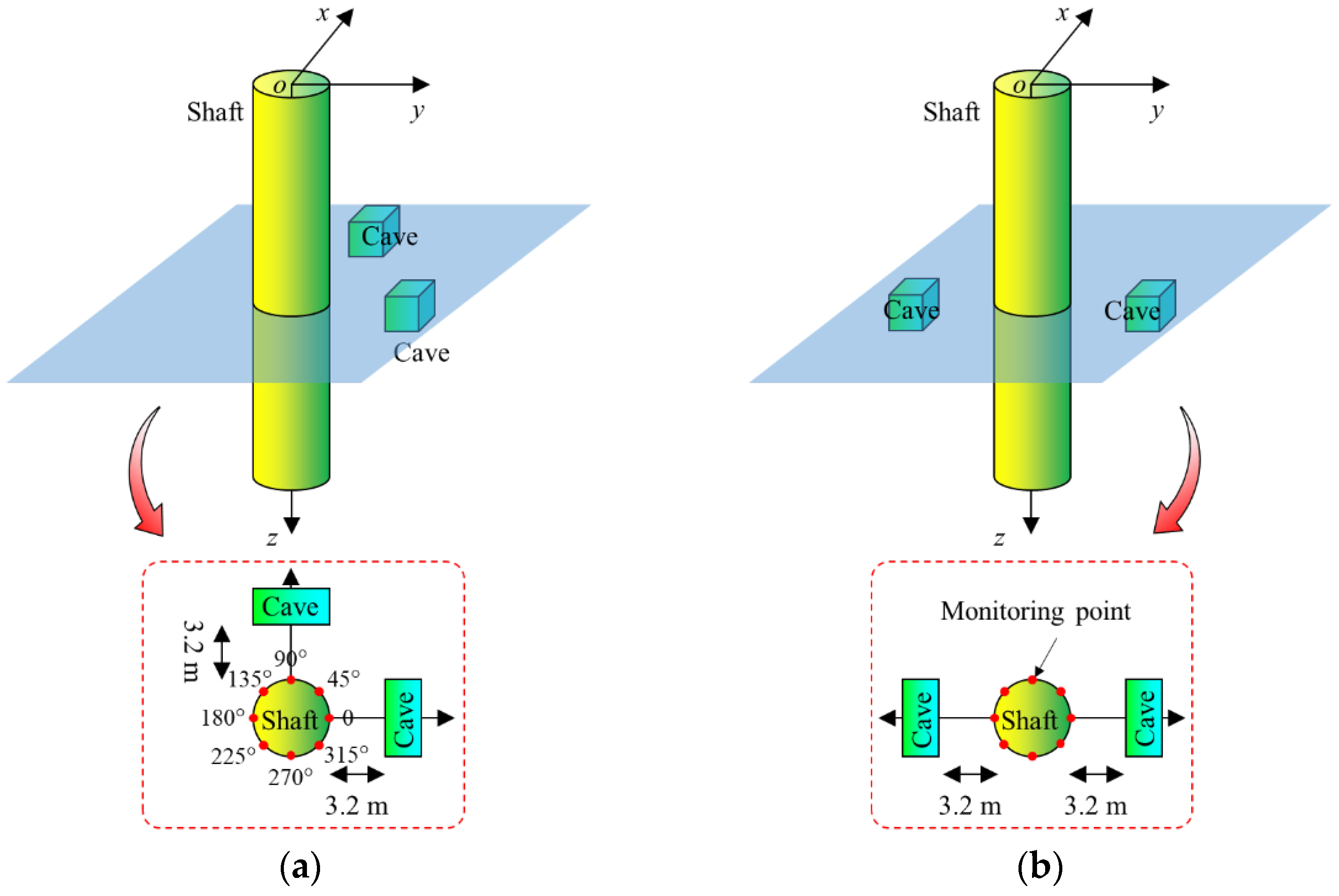
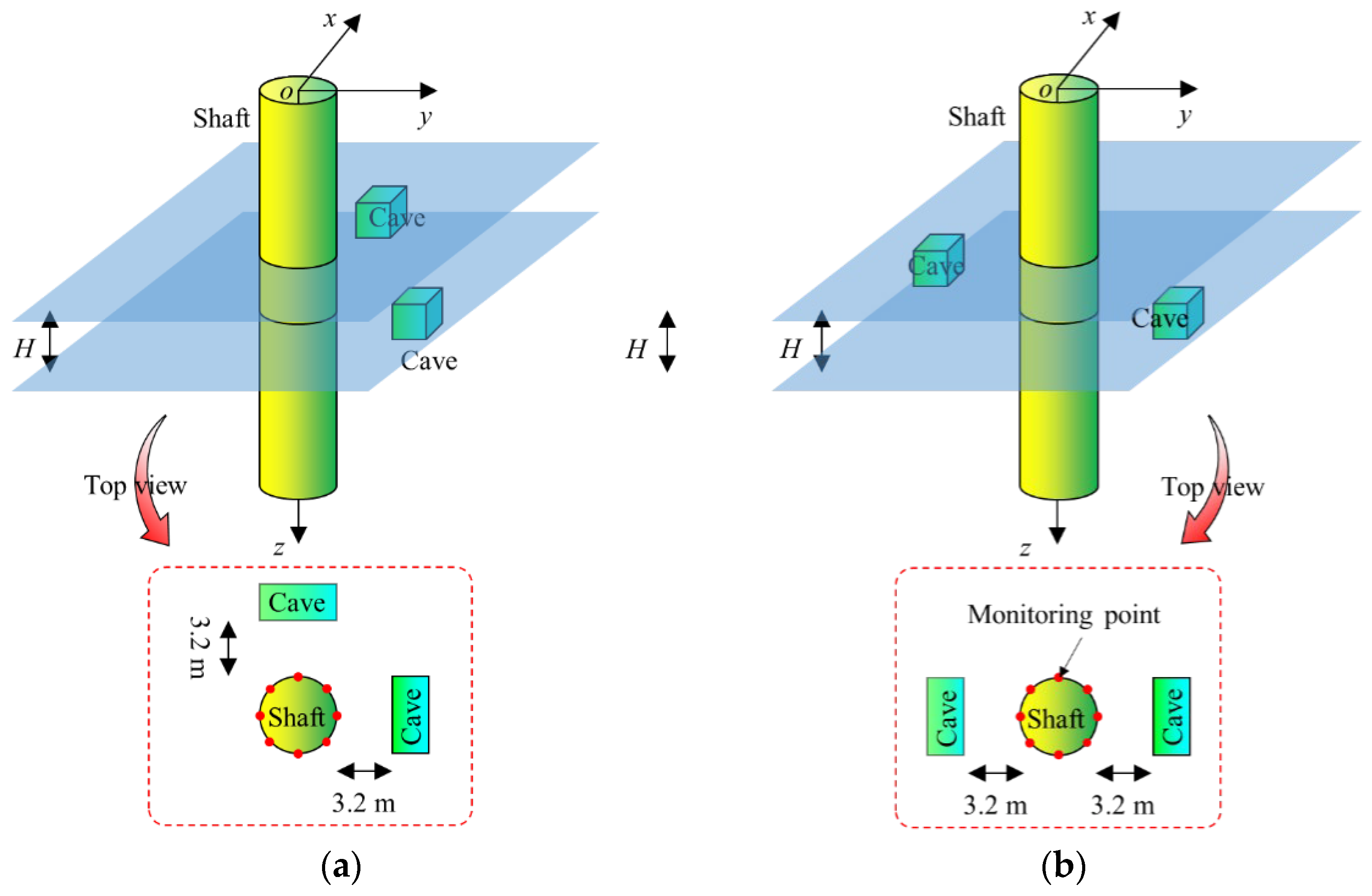
The present study investigates the impact of two karst cavities on the stability of the surrounding rock during shaft excavation. Initially, the scenario where the two cavities lie in the same horizontal plane, with configurations of vertical alignment and symmetric distribution, was analyzed. The corresponding geometric layout is illustrated in
Figure 5.
4. Simulation Results and Analysis
To investigate the influence of two karst cavities arranged in different configurations within the same horizontal plane on the stability of surrounding rock during deep and large-diameter shaft excavation, the radial displacement and radial stress of the surrounding rock were selected as the primary evaluation indicators. The analysis focuses on the variation in rock displacement and stress with depth, aiming to reveal the evolution patterns of shaft lining stability during different construction stages.
4.1. Influence of Vertically Aligned Cavities on Surrounding Rock Stability
4.1.1. Variation in Radial Displacement with Depth Under Vertical Cavity Conditions
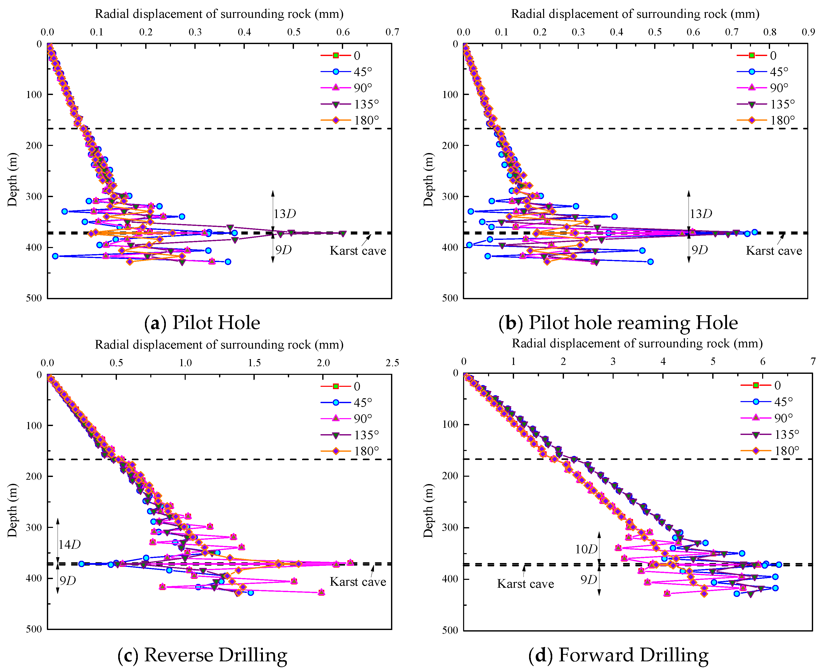
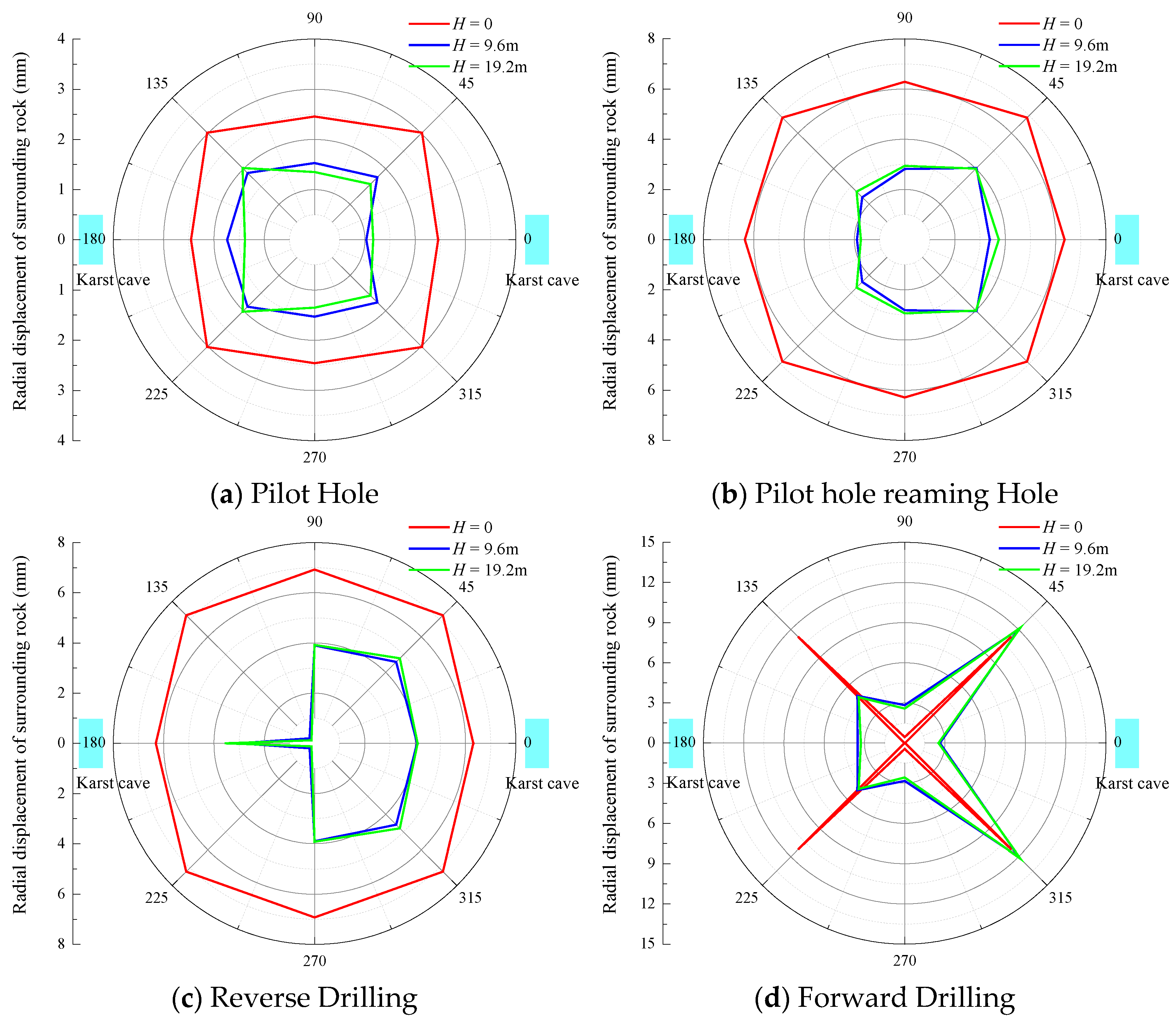
By conducting a full-process simulation of the shaft excavation using the Raise Boring Machine (RBM) method, the variation in radial displacement of the surrounding rock with depth under the influence of vertically aligned karst cavities was obtained. The results for different orientations around the shaft are shown in
Figure 6.
As shown in
Figure 6, the numerical simulation results of different construction stages using the Raise Boring Machine (RBM) method indicate that the radial displacement of the surrounding rock at various orientations increases with depth. Peak radial displacement occurs at the locations of the karst cavities across all four construction stages. Notably, during the reverse reaming stage, the maximum radial displacement of the surrounding rock within the cavity zone (2.0–2.5 mm) is significantly lower than that observed during the forward reaming stage (6.0–7.5 mm), and the displacement gradient is relatively gentle. These results suggest that the bottom-up reaming sequence effectively mitigates stress redistribution-induced disturbances at the cavity boundaries.
The influence of the cavities on surrounding rock stability exhibits significant asymmetry. As the planar angle between the two cavities increases, abrupt displacement zones develop near the cavity roofs, where particular attention must be paid during construction to prevent roof collapse risks.
4.1.2. Variation in Radial Stress with Depth Under Vertical Cavity Conditions
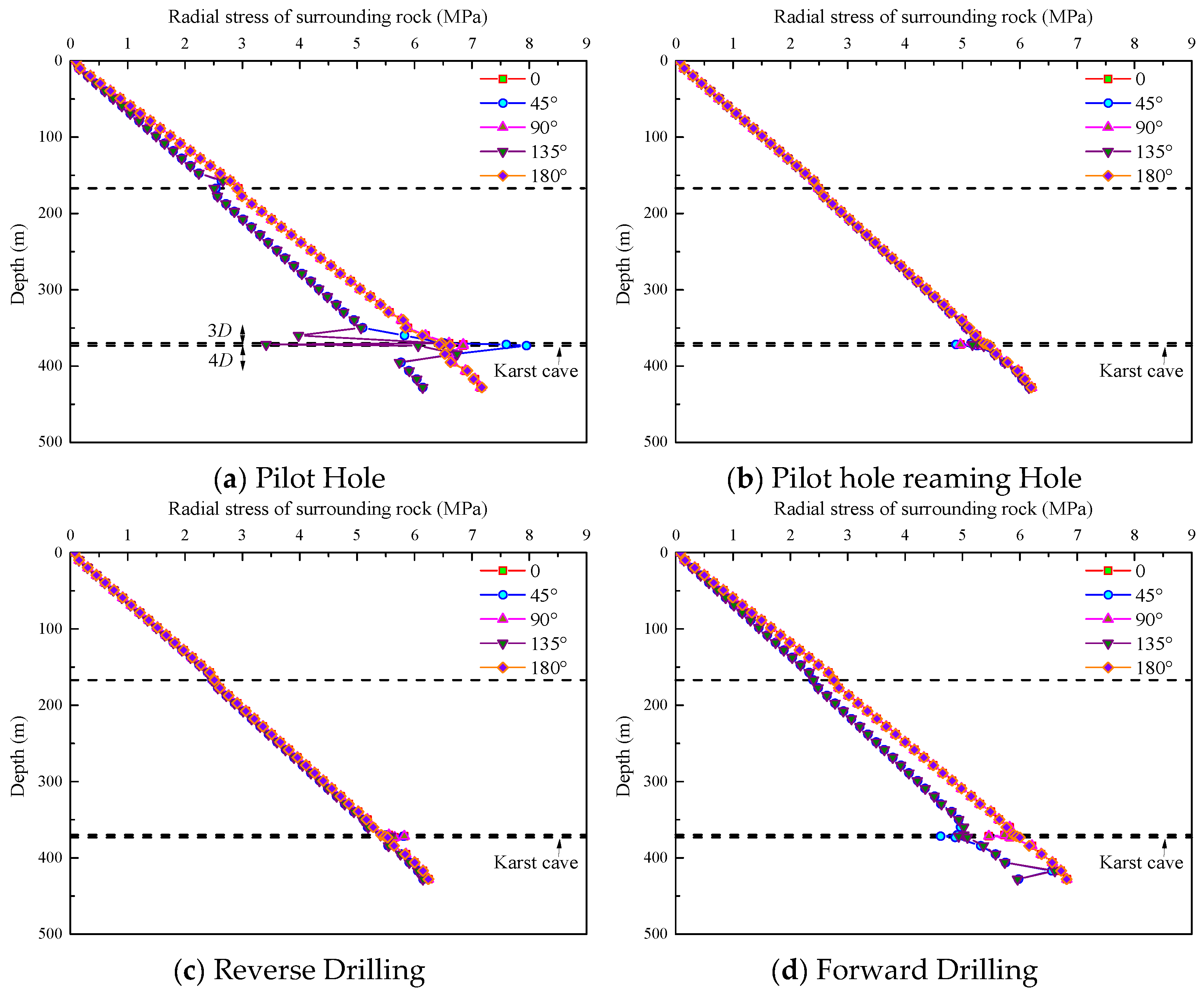
To further investigate the variation pattern of surrounding rock stability with depth in the presence of vertically aligned karst cavities within the same horizontal plane during Raise Boring Machine (RBM) excavation, the changes in radial stress were analyzed.
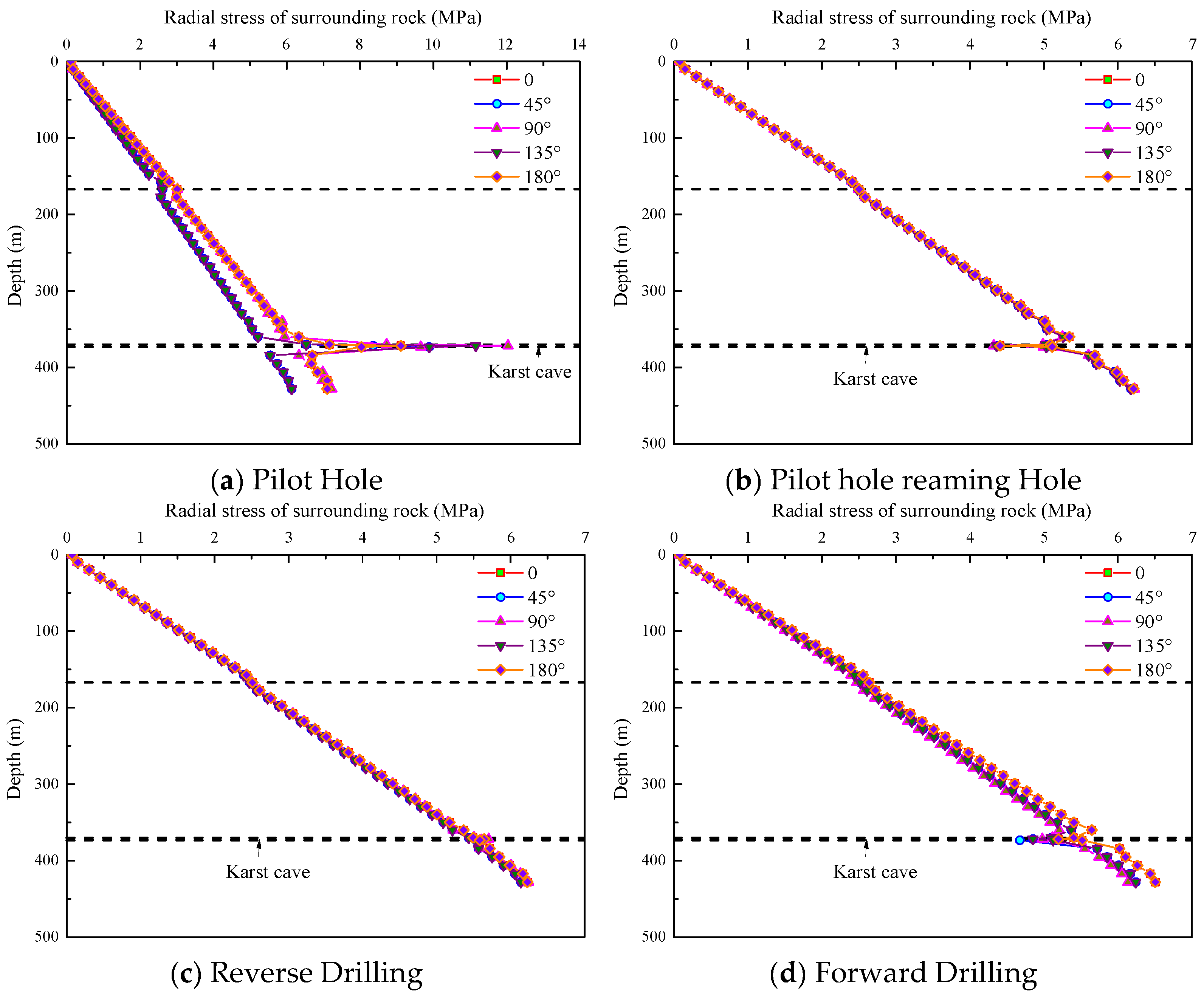
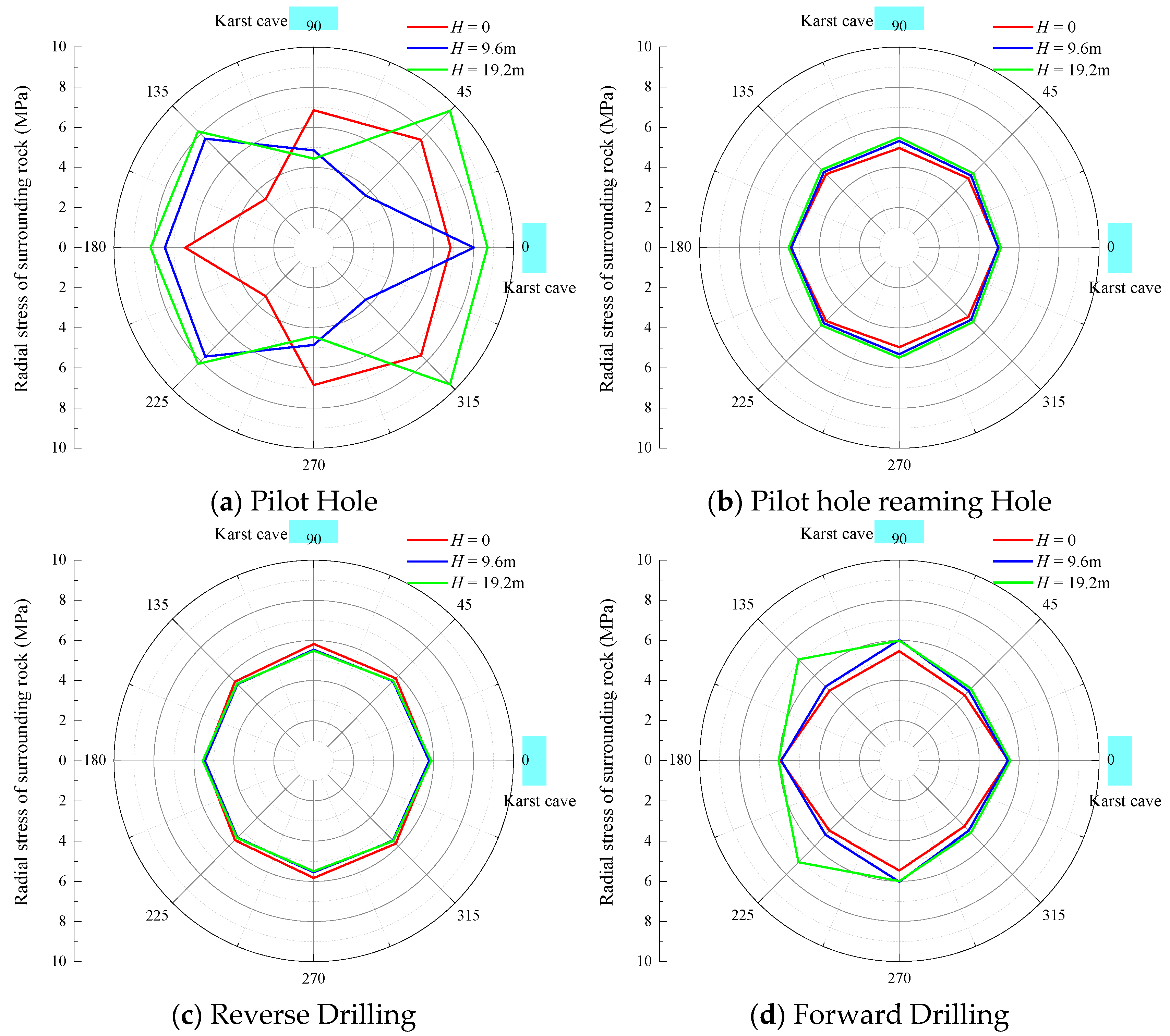
Figure 7 illustrates the variation in radial stress in the surrounding rock with depth under the influence of vertically aligned karst cavities at different construction stages, based on numerical simulation results. It can be seen that during the reverse reaming stage, the radial stress distribution near the cavities exhibits a significant advantage: the maximum radial stress at the cavity roof (depth of 400 m) reaches 6 MPa, which is lower than that observed during the forward reaming stage, and the radial stress gradient is comparatively gentle. These findings indicate that the bottom-up construction sequence of the reverse reaming process effectively alleviates stress concentration around the cavity boundaries.
The impact of the cavities on the surrounding rock stress exhibits spatial heterogeneity. As the spatial angle within the shaft increases, the radial stress of the surrounding rock decreases with depth. When the angle ranges from 0° to 90°, the radial stress reaches its maximum value.
4.2. Influence of Symmetrical Cavities on Surrounding Rock Stability
4.2.1. Variation in Radial Displacement with Depth Under Symmetrical Cavity Conditions
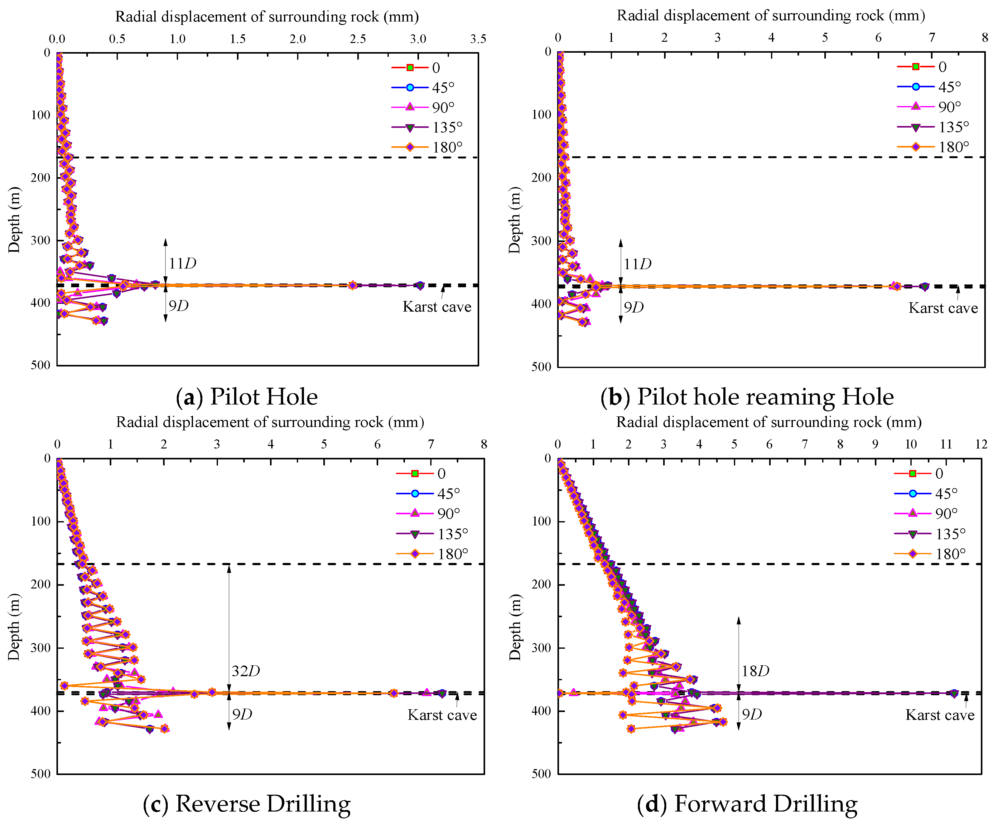
Further investigation was conducted on the stability variation in the surrounding rock with depth during excavation in the presence of symmetrical karst cavities. The study first focused on analyzing the variation in radial displacement with depth.
As shown in
Figure 8, the radial displacement of the surrounding rock increases progressively with reaming depth across all four construction stages in the numerical simulation, with peak displacement occurring at the locations of the karst cavities. The maximum radial displacement during the reverse reaming stage at the cavity zone is approximately 7 mm, which is smaller than that observed during the forward reaming stage (11 mm). This reduction is attributed to the bottom-up excavation sequence effectively mitigating stress concentration around the cavity boundaries, consistent with actual construction observations. Furthermore, the radial displacement during the pilot hole stage is significantly smaller than that during the subsequent reaming stages. This is primarily due to the influence of symmetrically distributed cavities, where the in situ stress maintains a symmetric spatial distribution during the pilot hole stage, thereby preserving the overall stability of the surrounding rock.
In terms of spatial distribution, the maximum displacement occurs at 135°. These findings indicate that under the influence of symmetrical cavities, the reverse reaming stage technique can effectively control deep surrounding rock deformation compared to the forward reaming stage method in karst formations with symmetrical cavities.
4.2.2. Variation in Radial Stress with Depth Under Symmetrical Cavity Conditions
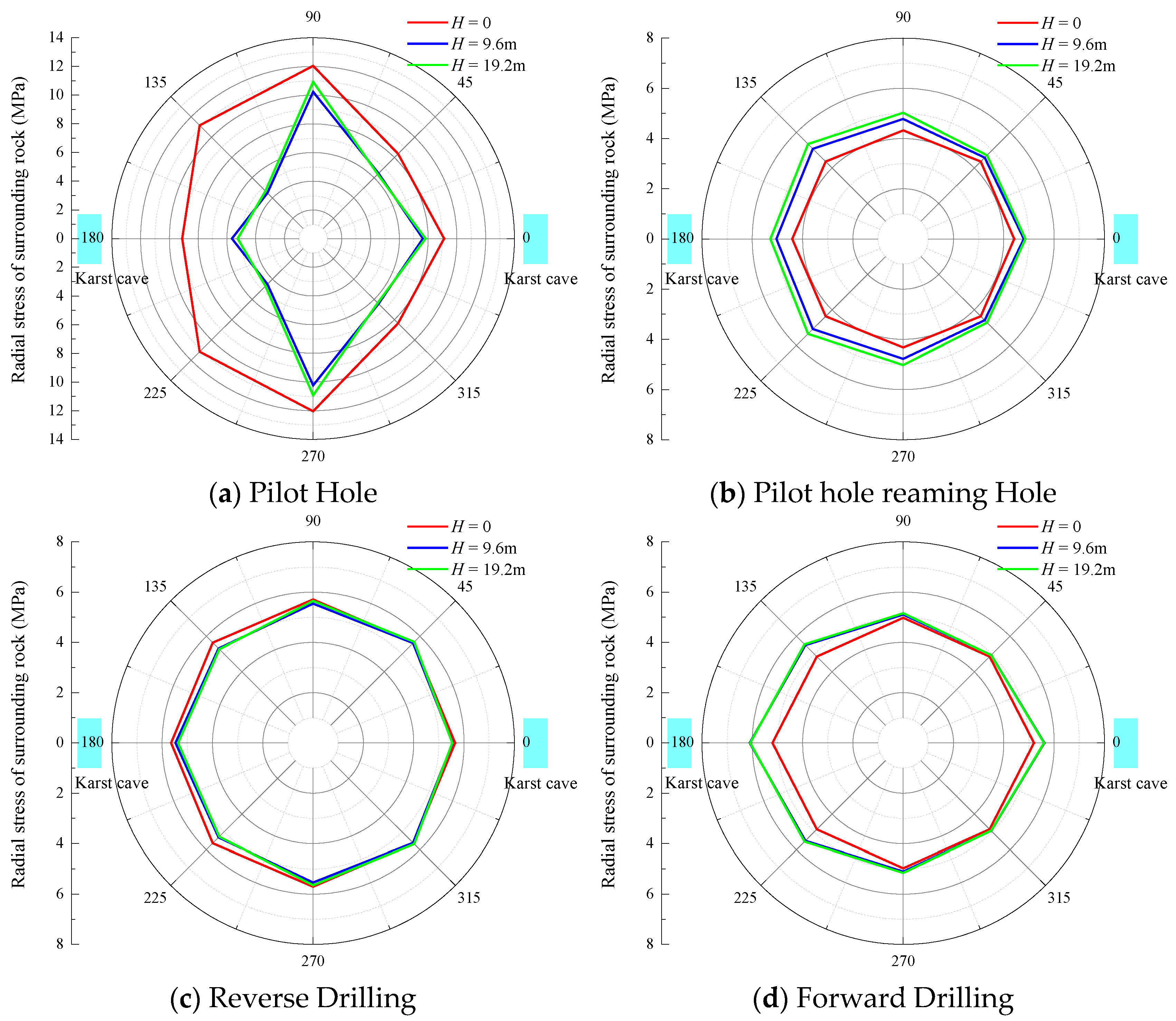
Further analysis was conducted on the variation in surrounding rock stability with depth under the influence of symmetrical cavities during the numerical simulation process. The variation in radial stress in the surrounding rock at different construction stages with depth was investigated, as shown in
Figure 9.
As shown in
Figure 9, the radial stress curves for both the forward and reverse reaming stages exhibit similar trends with increasing depth. The radial stress remains relatively stable along the shaft depth, except at the cavity locations, where the surrounding rock shows distinct differences in stress response. Specifically, during the reverse reaming stage, the radial stress near the cavities slightly increases, while during the forward reaming stage, it significantly decreases. This can be attributed to the bottom-up excavation sequence of the reverse reaming stage, which provides continuous support and helps maintain the self-bearing capacity of the surrounding rock around the cavities. In contrast, the forward reaming stage, with its excavation direction aligned with the gravitational field, aggravates tensile damage to the cavity roof.
During the pilot hole stage, the radial stress at the cavity locations reaches a peak of 12 MPa, followed by a noticeable stress reduction during the reaming stages. This is mainly due to the influence of symmetrically distributed cavities, which reduce the overall stability of the surrounding rock, resulting in a corresponding increase in radial displacement during the pilot hole stage. The pronounced radial stress peak observed in the pilot hole stage reflects the initial disturbance and impact of excavation on the intact rock mass. In contrast, the reaming stages progressively release stress through staged unloading combined with support measures, effectively achieving dynamic equilibrium of the stress field.
5. Parameter Analysis
In reality, multiple cavities may not be located on the same plane but at different depths in space. To further understand the impact of multiple cavities at different depths on the stability of surrounding rock during shaft excavation, this section focuses on a comparative analysis of the influence of cavity relative positions on the same plane versus different planes on surrounding rock stability.
5.1. Influence of Cavity Relative Position on the Same Plane
5.1.1. Variation in Radial Displacement of Surrounding Rock
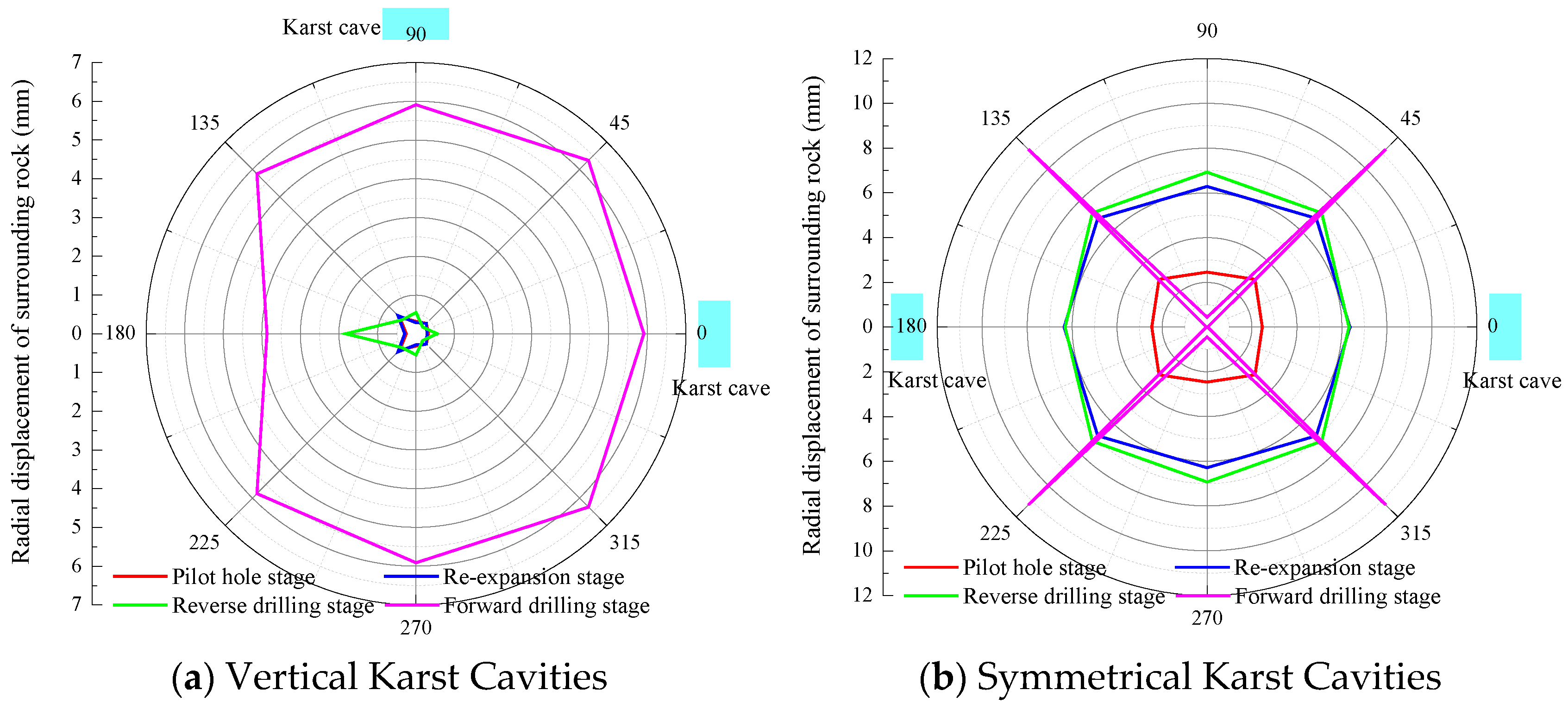
Figure 10 illustrates the effects of different relative positions of cavities on the same plane at various construction stages on the radial displacement of the surrounding rock. As shown in
Figure 10, both the reaming stage and the forward reaming stage have the most significant influence on the radial displacement, which is likely due to the greater excavation forces and vibrations applied during these stages. Moreover, the radial displacement of the surrounding rock under symmetrical cavity conditions is generally larger than that under vertically aligned cavity conditions. This phenomenon is primarily attributed to the more complex geological structures associated with symmetrical cavity configurations, making the rock mass more susceptible to deformation during excavation. For shaft sections with symmetrical cavities, it is recommended to conduct more detailed geological investigations and adopt stricter construction monitoring measures to prevent engineering accidents caused by excessive rock displacement.
5.1.2. Variation in Radial Stress in Surrounding Rock on the Same Plane
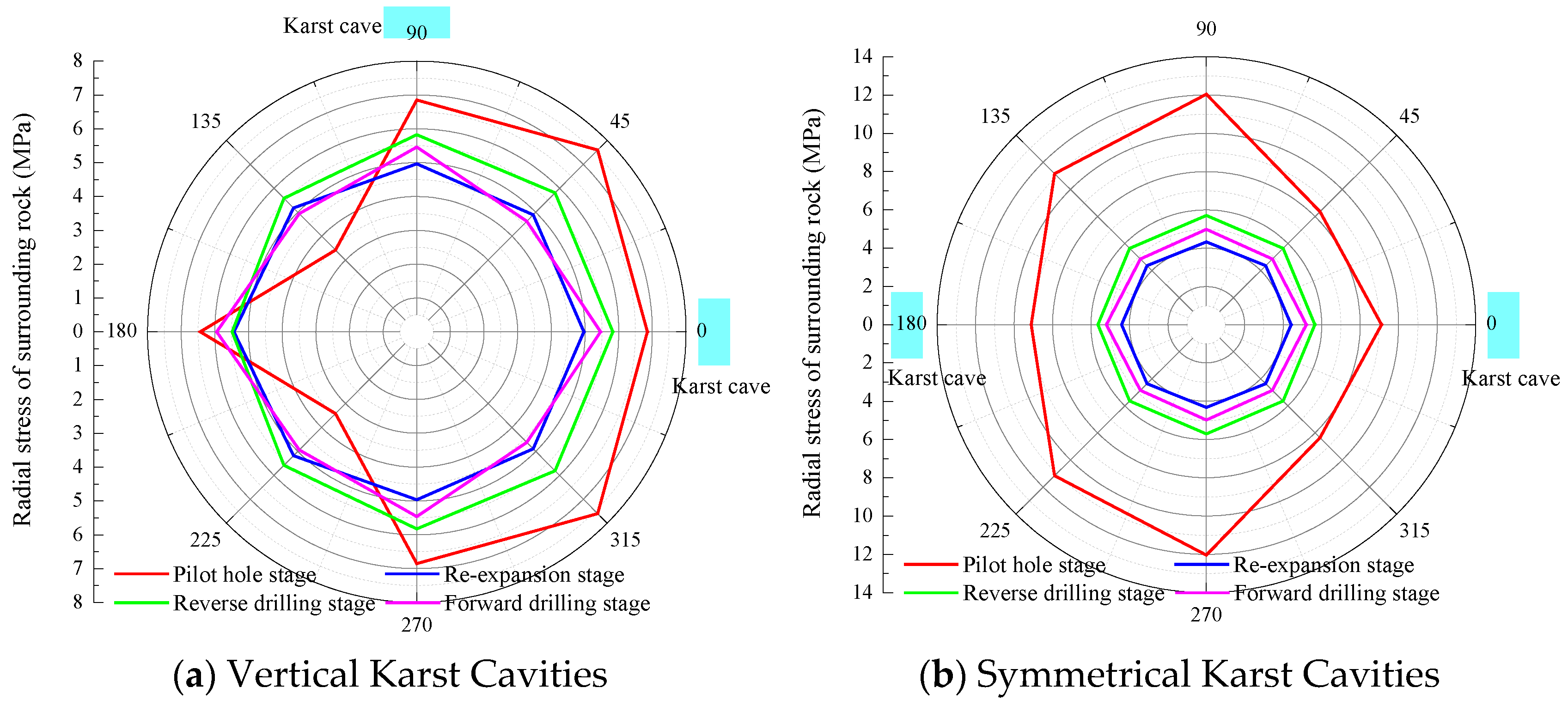
Figure 11 illustrates the effects of different relative cavity positions on the same plane at various construction stages on the radial stress of the surrounding rock. It can be seen from
Figure 11 that as the reaming progresses, the radial stress in the rock exhibits a complex variation pattern, with particularly significant changes observed during the reaming and forward reaming stages. This indicates that increased excavation forces and vibrations during these stages cause substantial alterations in the rock stress state.
Figure 11b presents a similar trend under symmetrical cavity conditions; however, the stress distribution and peak values differ. Specifically, while the reaming and forward reaming stages still induce the most pronounced radial stress variations, the overall stress levels are higher than those observed in the case of vertically aligned cavities. This suggests that the geological structures associated with symmetrical cavity configurations exert a greater influence on the excavation process, resulting in more significant stress redistribution within the surrounding rock.
Based on detailed analysis of
Figure 11a,b, the following conclusions can be drawn: During reaming, particularly in the reaming and forward reaming stages, the radial stress of the surrounding rock is markedly affected. This impact is more significant in the presence of symmetrical cavities, likely due to the complex geological structure associated with such formations.
5.2. Influence of Relative Positions of Cavities on Different Planes
5.2.1. Variation in Radial Displacement in Surrounding Rock
The spatial relationship between the two cavities located on different planes and the shaft is illustrated in
Figure 12.
Figure 13 illustrates the influence of the spacing between vertically aligned cavities located on different planes on the radial displacement of the surrounding rock. It can be observed from
Figure 13 that the distance between the planes where the cavities are located has a significant impact on the radial displacement of the rock mass between the cavities. As the spacing between the two cavities increases, the radial displacement of the surrounding rock progressively increases during the pilot hole excavation, reaming, reverse reaming, and forward reaming stages.
Under these conditions, the radial displacement of the surrounding rock changes only slightly during the pilot hole and reaming stages. However, during the forward reaming stage, the radial displacement increases significantly, exceeding that observed during the reverse reaming stage and representing the maximum displacement among all four excavation methods. This finding indicates that the forward reaming stage causes the most severe damage to the stability of the surrounding rock during the excavation of vertical cavities located on different planes. Therefore, enhanced monitoring and reinforcement measures are required during this stage to ensure construction safety.
Figure 14 illustrates the influence of the spacing between planes where symmetrical cavities are located on the radial displacement of the surrounding rock. As shown in
Figure 14, the radial displacement of the surrounding rock in symmetrical cavity conditions is inversely proportional to the spacing between the two cavities, with the largest and most pronounced displacement occurring during the forward reaming stage. In terms of spatial distribution, the radial displacement of the surrounding rock presents a clear symmetrical pattern.
By comparing the variations in radial displacement of the surrounding rock between symmetrical and vertically aligned cavities under different plane spacings, it can be concluded that the radial displacement is more sensitive to plane spacing in vertically aligned cavities. Among the four construction stages, the forward reaming stage is most significantly affected by the plane spacing, resulting in the largest variations in the radial displacement of the surrounding rock.
5.2.2. Variation in Radial Stress in Surrounding Rock
Figure 15 illustrates the influence of the spacing between planes where vertically aligned cavities are located on the radial stress of the surrounding rock. As shown in
Figure 15, with the increase in spacing between the two cavities, the peak radial stress of the surrounding rock during the pilot hole excavation stage reaches its maximum, indicating that the rock mass is least stable under this condition. As the plane spacing continues to increase, the radial stress of the surrounding rock also increases. However, during the subsequent construction stages, the variations in radial stress are relatively minor.
Specifically, at the 0° orientation, the radial stress of the surrounding rock increases as the plane spacing increases, whereas at the 90° orientation, the radial stress decreases with greater plane spacing. During the reaming, reverse reaming, and forward reaming stages, the increase in plane spacing has minimal impact on the radial stress of the surrounding rock. Moreover, the stress distribution around the cavities remains relatively stable without sudden fluctuations.
As shown in
Figure 16, for symmetrically distributed cavities, the radial stress of the surrounding rock at the cavity locations exhibits significant variation during the pilot hole excavation stage, while the changes in radial stress during the subsequent construction stages are relatively minor. Notably, pronounced stress fluctuations occur around the cavities, primarily due to stress concentration effects induced by the presence of the cavities.
However, it can be observed that as the spacing between the two cavity planes increases, the overall variation in radial stress of the surrounding rock under all four excavation stages remains minimal. This indicates that plane spacing has a limited influence on radial stress variations in the case of symmetrically distributed cavities.
6. Conclusions
This study employed ABAQUS finite element software to simulate the full excavation process of the ventilation shaft at the Zimuyan Tunnel using the Raise Boring Method (RBM), with a focus on the effects of karst cavities. By analyzing the radial displacement and stress of the surrounding rock under various working conditions, the following conclusions were drawn:
ABAQUS effectively replicates the RBM excavation process, with simulated deformation and stress trends closely aligning with field observations. Although the model adopted simplified cavity geometry and excluded hydrogeological factors such as groundwater pressure, the simulation results aligned well with observed deformation trends during field construction. This provides preliminary validation of the model’s reliability in evaluating mechanical behavior under multiple-cavity conditions.
RBM shows clear benefits in multi-cavity karst formations. During reverse reaming, radial displacement is reduced by approximately 60%, and stress concentration by about 40% compared to forward reaming. The bottom-up sequence helps alleviate stress disturbances, particularly around cavity boundaries, demonstrating better control over stress on the cavity roof.
Symmetrically arranged cavities impose greater challenges than vertically aligned ones. On the same plane, radial displacement near symmetrical cavities is 15%–20% higher, and the stress field becomes more complex, indicating the need for enhanced support.
Larger spacing between cavities significantly improves rock stability. For cavities on different planes, when spacing exceeds 2D (shaft diameter), displacement gradients stabilize, making RBM particularly effective. If spacing is less than 1D, pre-grouting reinforcement is recommended.
In this study, the influence of cavity size was not considered due to limitations in computational resources and modeling constraints. Future work will focus on incorporating a parametric study of cavity dimensions to better understand their role in excavation-induced stress redistribution and deformation patterns in karst formations. Additionally, a sensitivity analysis on cavity size, which was fixed in this study, will be incorporated in future research to broaden the applicability of the findings to more diverse karst conditions.
Author Contributions
Methodology, F.D.; Validation, H.X.; Formal analysis, Y.F., G.W. and K.R. All authors have read and agreed to the published version of the manuscript.
Funding
This research was funded by the Department of Transportation Science and Technology of Guizhou Province, China. Grant number No. 2023-122-007.
Data Availability Statement
The original contributions presented in the study are included in the article, further inquiries can be directed to the corresponding author.
Conflicts of Interest
Authors Yongqiao Fang, Guofeng Wang, Kaifu Ren and Fayi Deng were employed by the company Guizhou Road and Bridge Group Co., Ltd. The remaining authors declare that the research was conducted in the absence of any commercial or financial relationships that could be construed as a potential conflict of interest.
References
- Li, B.; Li, B.; Wang, Y. Application of Reverse Drilling Method in the Excavation of Shaft at Sanhe Reservoir. Haihe Water Conserv. 2024, 11, 121–124+128. [Google Scholar]
- Tangjarusritaratorn, T.; Miyazaki, Y.; Sawamura, Y.; Kishida, K.; Kimura, M. Numerical Investigation on Arching Effect Surrounding Deep Cylindrical Shaft during Excavation Process. Undergr. Space 2022, 7, 944–965. [Google Scholar] [CrossRef]
- Tang, B.; Cheng, H.; Tang, Y.; Yao, Z.; Rong, C.; Wang, X.; Xue, W.; Guo, S. Experiences of Gripper TBM Application in Shaft Coal Mine: A Case Study in Zhangji Coal Mine, China. Tunn. Undergr. Space Technol. 2018, 81, 660–668. [Google Scholar] [CrossRef]
- Chen, G.; Meng, C.; Zhang, C. Application of Reverse Drilling Method in Ventilation Shaft of Extra-long Highway Tunnel. Value Eng. 2023, 42, 82–84. [Google Scholar]
- Wang, Q. Construction Technology of Reverse Drilling Method for Ventilation Shaft of Zhongnan Mountain Extra-long Tunnel. Rail. Stand. Des. 2008, 9, 77–78. [Google Scholar] [CrossRef]
- Cheng, S. Research and Application of Reverse Drilling Method in Deep Shaft Construction of Railway Tunnel: A Case Study of Dangjinshan Tunnel. Tunn. Constr. (Chin. Engl. Ed.) 2018, 38, 1560–1565. [Google Scholar]
- Huang, R. Application of Reverse Drilling Method in Oil Shaft Excavation of Shidong Oil Depot Project. Water Conserv. Hydroelectr. Technol. (Chin. Engl. Ed.) 2022, 53, 191–195. [Google Scholar] [CrossRef]
- Li, Y.; Dong, X.; Cao, X.; Xu, P. Study on Control Dimensions of Muck in Shaft Reverse Drilling Method. Mod. Tunn. Technol. 2023, 60, 194–202. [Google Scholar] [CrossRef]
- Zhao, W.; Fang, B.; Zhang, Z. Discussion on Reverse Drilling Method for Ventilation Shaft of Micangshan Extra-long Tunnel. Highway 2014, 59, 182–187. [Google Scholar]
- Hashiba, K.; Fukui, K.; Kitahara, M.; Kiyama, R.; Okutsu, K. Estimation of Rock Mass Conditions During Shaft Excavation with the Raise Boring Method. In Proceedings of the ISRM International Symposium–10th Asian Rock Mechanics Symposium (ISRM-ARMS10), Singapore, 29 October 2018. [Google Scholar]
- Stakne, P. Deep shaft boring by raise boring process—Practical considerations. Geotechnik 2015. [Google Scholar]
- Auvinet-Guichard, G.; Rodríguez-Rebolledo, J.F.; Rangel-Núnez, J.L. Construction of Deep Tunnel Shafts in Mexico City Soft Clays by the Flotation Method. Acta Geotech. 2010, 5, 63–68. [Google Scholar] [CrossRef]
- Grossekemper, J.; Tonscheidt, H.W. Raise boring to full shaft diameter now possible. Glueckauf 1980, 116. [Google Scholar]
- Fourie, A. Using an integrated model for shaft sinking method selection. J. Civ. Eng. Manag. 2006, 17, 569–580. [Google Scholar]
- Semin, M.; Levin, L. Theoretical Study of Partially Return Air Flows in Vertical Mine Shafts. Therm. Sci. Eng. Prog. 2021, 23, 100884. [Google Scholar] [CrossRef]
- Kazakov, B.P.; Shalimov, A.V.; Semin, M.A. Stability of Natural Ventilation Mode after Main Fan Stoppage. Int. J. Heat Mass Transf. 2015, 86, 288–293. [Google Scholar] [CrossRef]
- Guo, C.; Li, Z.; Zhu, H.; Zhao, L.; Yan, Z. Single-Channel Blowing-In Longitudinal Ventilation Method and Its Application in Road Tunnel. Tunn. Undergr. Space Technol. 2021, 108, 103692. [Google Scholar] [CrossRef]
- Szlazak, N.; Obracai, D.; Korzec, M. Analysis of Connecting a Forcing Fan to a Multiple Fan Ventilation Network of a Real-Life Mine. Process Saf. Environ. Prot. 2017, 107, 468–479. [Google Scholar] [CrossRef]
- Guo, F. Numerical Simulation Study on Raise Boring Machine (RBM) Method and Shaft Wall Stability in Tongsheng Tunnel Ventilation Shaft. Master’s Thesis, Wuhan University of Technology, Wuhan, China, 2015. [Google Scholar]
- Shaoxing Transportation Construction Co., Ltd.; China Railway Tunnel Group Co., Ltd.; Zhejiang Communications Investment Group Co., Ltd. Research on Construction Technology of Deep and Large Ventilation Shaft Using Raise Boring Machine in Highway Tunnel; Zhejiang Provincial Department of Transportation: Hangzhou, China, 2021. [Google Scholar]
- Wu, D. Study on Surrounding Rock Stability of Deep Shaft Construction. Master’s Thesis, Shandong University of Science and Technology, Qingdao, China, 2011. [Google Scholar]
- Wang, S. Numerical Simulation Analysis of Stability During Large-Diameter Shaft Excavation. Proj. Manag. 2023, 8, 105–108. [Google Scholar]
- Wang, C.; Zhang, Y.; Li, X. Numerical Analysis of Stress Concentration Due to Pilot Hole Deviation in Raise Boring. Tunn. Undergr. Space Technol. 2023, 134, 104832. [Google Scholar]
- Zhang, Q.; Liu, Q.; Zhang, Z. Simulation of Rock Breaking Based on FEM-CZM Method and Its Application in Disc Cutter Parameter Optimization. Geotech. Geol. Eng. 2022, 40, 2843–2856. [Google Scholar] [CrossRef]
- Alejano, L.R.; Alontherefore, E.; Olalla, C. Application of Cohesive Zone Models to Predict Block Detachment in Jointed Rock Masses. Int. J. Rock Mech. Min. Sci. 2018, 110, 1–10. [Google Scholar]
- Liu, Y.; Weng, L.; Chu, Z. Numerical Investigation of Rock Dynamic Fragmentation During Rockslides Using a Coupled 3D FEM-DEM Method. J. Mt. Sci. 2022, 19, 1051–1069. [Google Scholar] [CrossRef]
- Beck, D.; Brady, B.H.G.; Stacey, T.R. Modeling of Thermo-Hydro-Mechanical Coupling in Deep Underground Excavations. Int. J. Rock Mech. Min. Sci. 2019, 122, 104073. [Google Scholar]
- Li, S.; Zhang, J.; Wang, H. Study on Seepage–Stress Coupling Effects in Hydraulic Raise Boring and Development of Real-Time Monitoring Models. Rock Soil Mech. 2021, 42, 1357–1365. [Google Scholar]
- Schaumann, M.; Gamba, D.; Morales, H.G.; Corsini, R.; Guinchard, M.; Scislo, L.; Wenninger, J. Muography Imaging of the Internal Structure of a Cultural Heritage Site Using Nuclear Emulsion Detectors. Nucl. Instrum. Methods Phys. Res. Sect. A 2023, 1050, 168495. [Google Scholar] [CrossRef]
- Saadati, M.; Djeran-Maigre, I.; Sai, K.; Richard, T.; Pizette, P.; Dano, C. On the Mechanical Behavior of Granite: Constitutive Modeling and Application to Percussive Drilling. Rock Mech. Rock Eng. 2015, 48, 2397–2412. [Google Scholar]
- Hu, J.; Gong, F.; Li, X.; Wang, S.; Tao, M.; Du, K.; Luo, Y.; Song, J. Numerical Simulation and Experimental Studies of Rock Breaking with Different Hob Profiles under High Geo-Stress Conditions. Int. J. Rock Mech. Min. Sci. 2020, 131, 104348. [Google Scholar] [CrossRef]
- Sun, H.; Yang, H.; Wang, Z. Finite Element Method for Prediction of Rock Breaking in Raise Boring. Tunn. Undergr. Space Technol. 2018, 71, 200–212. [Google Scholar] [CrossRef]
- Li, B.; Li, B.; Wang, Y. The Influence of the Drilling Rate of the Raise Boring Machine on Rock Breaking Efficiency. Rock Soil Mech. 2023, 44, 3498–3508. [Google Scholar]
- Liu, J.; Meng, C. Key Technologies of Drilling Process with Raise Boring Method. Coal Sci. Technol. 2015, 43, 94–98. [Google Scholar] [CrossRef]
- Guo, L.; Liu, J.; Zhang, J.; Zhou, Y. Evaluation Method of Shaft Structure Stability in Coal Mine Raise Boring. J. China Coal Soc. 2020, 45, 1763–1773. [Google Scholar]
- Han, G.; Zhang, H.; Wang, Z.; Wang, Y.; Geng, N.; Guo, P.; Li, X.; Zhao, Y.; Lin, H.; Wang, Y. Bearing behavior of rock socketed pile in limestone stratum embedded with a karst cavity beneath pile tip. Case Studies Const. Mater. 2023, 18, e02203. [Google Scholar] [CrossRef]
- Wu, B.; Sun, W.; Cai, G.; Meng, G. Reliability Analysis of Shallow-buried Tunnel Construction Adjacent to Karst Cave. Comput. Geotech. 2022, 145, 104673. [Google Scholar] [CrossRef]
- Shaterpour, A. Raise boring machines–A comprehensive review of performance prediction and operational challenges. Tunn. Undergr. Space Technol. 2025, 156, 106246. [Google Scholar] [CrossRef]
- Wang, G.; Deng, F.; Ren, K.; Fang, Y.; Xu, H. Finite Element Analysis of the Excavation Stability of Deep and Large Ventilation Shafts of Zimuyan Tunnel Using the Raise Boring Machine Method in a Karst Area. Buildings 2025, 15, 287. [Google Scholar] [CrossRef]
- Wang, Q.K.; Hu, Z.B.; Guo, Y.J.; Ji, Y.K.; Zhu, B.L.; Ma, J.L. Investigation on uplift behavior of rock-socketed belled piles in horizontal and inclined ground using 1-g model test and 3D numerical method. Rock Mech. Rock Eng. 2024, 57, 3371–3391. [Google Scholar] [CrossRef]
- Cheng, L.; Yu, L.; Wang, M.N.; Xia, P.X.; Sun, Y. Upper bound analysis of collapse failure of deep tunnel under karst cave considering seismic force. Soil Dyn. Earthq. Eng. 2020, 132, 106003. [Google Scholar] [CrossRef]
- Li, S.C.; Wu, J.; Xu, Z.H.; Zhou, L.; Zhang, B. A possible prediction method to determine the top concealed karst cave based on displacement monitoring during tunnel construction. Bull. Eng. Geol. Environ. 2019, 78, 341–355. [Google Scholar] [CrossRef]
- Ma, J.J.; Guan, J.W.; Duan, J.F.; Huang, L.C.; Liang, Y. Stability analysis on tunnels with karst caves using the distinct lattice spring model. Undergr. Space 2021, 6, 469–481. [Google Scholar] [CrossRef]
- Sun, J.L.; Wang, Y.; Wu, X.; Wang, X.L.; Fang, H.; Su, Y. Research on Collapse Risk Assessment of Karst Tunnels Based on BN Self-Learning. Buildings 2024, 14, 685. [Google Scholar] [CrossRef]
- Vipulanandan, C.; Wong, D.; Ochoa, M.; O’Neill, M.W. Modeling of displacement piles in sand using a pressure chamber. In Foundation Engineering: Current Principles and Practice; ASCE: New York, NY, USA, 1989; pp. 526–541. [Google Scholar]
- Lee, J.; You, K.; Jeong, S.; Kim, J. Proposed point bearing load transfer function in jointed rock-socketed drilled shafts. Soils Found. 2013, 53, 596–606. [Google Scholar] [CrossRef]
- Tan, D.M.; Qi, T.Y.; Mo, Y.C. Numerical analysis and research on surrounding rock stability of lateral karst cave tunnel. Chin. J. Rock Mech. Eng. 2009, 28, 3497–3503. [Google Scholar]
| Disclaimer/Publisher’s Note: The statements, opinions and data contained in all publications are solely those of the individual author(s) and contributor(s) and not of MDPI and/or the editor(s). MDPI and/or the editor(s) disclaim responsibility for any injury to people or property resulting from any ideas, methods, instructions or products referred to in the content. |
© 2025 by the authors. Licensee MDPI, Basel, Switzerland. This article is an open access article distributed under the terms and conditions of the Creative Commons Attribution (CC BY) license (https://creativecommons.org/licenses/by/4.0/).
