Abstract
Tunnel engineering is frequently undertaken in complex geological environments, which present heightened risks during construction and operation, particularly in active fault zones. This necessitates the enhancement of fault resistance. This study investigates the combined application of Steel–polypropylene Fiber Concrete Linings and Combined Seismic Joints through numerical simulation using ABAQUS 2023 (Dassault Systèmes, France). The findings demonstrate that this combination significantly enhances the fault resistance of tunnel structures, exhibiting substantial synergistic effects. In comparison with the utilization of Steel–polypropylene Fiber Concrete Linings as a standalone measure, the maximum reductions in longitudinal tensile and compressive strain were found to be 40.1% and 46.7%, respectively. Furthermore, peak equivalent compressive and tensile plastic strains were reduced by 60.3% and 51.1%, and tensile and compressive damage by 4.9% and 17.3%. Further analysis reveals that the steel fiber aspect ratio and the content of both steel and polypropylene fibers have varying effects on suppressing different damage forms in tunnel linings. It is evident that an augmentation in the steel fiber aspect ratio most effectively suppresses plastic zone deformation, while an increase in polypropylene fiber content significantly reduces tensile strain and tensile damage. The optimal level of fault resistance performance is achieved when the steel fiber content is set at 1.90%, the aspect ratio is 60, and the polypropylene fiber content is 0.15%. Furthermore, the adjustment of the combined arrangement parameters enables tunnel structures to adapt more effectively to diverse operational conditions, thus providing flexible design solutions for practical engineering applications.
1. Introduction
In contrast to surface structures, which primarily bear gravitational loads from the ground surface, tunnel loads principally originate from the surrounding soil mass. The in situ stress of the surrounding rock can cause stress concentration in weaker zones of the tunnel, potentially leading to localized failure. This effect is particularly pronounced in fault fracture zones, where the soil-structure interaction becomes more complex and variable, introducing significant uncertainty into the tunnel’s load-bearing behavior [1,2]. Recent research has highlighted that tunnels intersecting active faults experience highly nonlinear deformation and stress transfer mechanisms, with fault movement strongly influencing lining performance and surrounding rock interaction [3].
In the event of a tunnel crossing a fault fracture zone, the structure is susceptible to combined damage mechanisms, including bending (cracking), tension, and shear (displacement) induced by fault dislocation. The long-term risks to the tunnel’s structural integrity are exacerbated by the cumulative effects of creep and stick-slip loading. The eventual outcome of these cumulative effects may be the triggering of sudden brittle failure, which would severely compromise the operational safety of the tunnel [4,5,6]. Hu et al. [7] further observed through field investigations and model tests that such tunnels often exhibit pronounced tensile cracking near the fault plane and shear displacement at the lining–rock interface, suggesting that conventional design approaches may underestimate localized damage.
Consequently, when engineering tunnels that traverse fault fracture zones, there is a necessity to emphasize enhancing their resistance to fault dislocation. This should include measures to mitigate the accumulation of displacement and stress that cannot be fully absorbed or counteracted by the lining structure. Mei et al. [8] numerically demonstrated that when fault slip is combined with seismic excitation, tunnel deformation tends to intensify nonlinearly, especially near the junction of different stiffness zones, which highlights the importance of combined mitigation strategies. Measures such as the incorporation of seismic joints and the utilization of Steel–Polypropylene Fiber Concrete Linings have been demonstrated to be efficacious in enhancing the tunnel’s deformation resistance [9,10].
Seismic joints have been found to demonstrate exceptional deformation resistance and are thus employed extensively in active fault zones, with a view to enhancing the fault-resisting performance of tunnels. Cheng et al. [11] proposed a comprehensive aseismic design framework integrating numerical and experimental methods, confirming that flexible joint systems can effectively reduce stress concentration and improve the seismic resilience of mountain tunnels. Zhao et al. [9] conducted a 1:100 scale shaking table model test to investigate the seismic response of the Xiangyangshan Highway Tunnel in China under varying seismic excitations. Their findings indicated that the inclusion of seismic joints resulted in a more uniform stress distribution within the tunnel lining, thereby significantly enhancing its fault-resisting capacity. Similarly, Cui et al. [10] employed a shaking table model to simulate and analyze the seismic performance of the soft rock portal section of a tunnel. The findings of this study demonstrated that the installation of seismic joints resulted in an improvement of the safety factor by 41.86% to 53.30%. The collective analysis of these studies emphasizes the effectiveness of seismic joints in enhancing the fault-resisting performance of tunnels.
Cui et al. [10] demonstrated through direct tensile tests that polypropylene fibers play a crucial role in inhibiting the propagation of microcracks in concrete and enhancing its toughness. Conversely, steel fibers have been shown to enhance the peak stress and strain of concrete by extending the path of macrocracks and limiting crack width [12,13]. Anastasopoulos et al. [12] further discovered that the combined use of steel and polypropylene fibers not only enhances the tensile performance of concrete but also significantly reduces drying shrinkage. Qian’s study [14] revealed that large-diameter steel fibers are more effective in enhancing split tensile strength, whereas small-diameter steel fibers are better suited for improving compressive strength. Research by Hosseinzadeh et al. [15] confirmed that steel–polypropylene fibers effectively enhance concrete’s resistance to crack propagation under tensile stress. Chi et al. [16], utilizing ABAQUS to establish a constitutive model for steel–polypropylene fiber-reinforced concrete, ascertained that the synergistic effect of steel and polypropylene fibers suppresses volumetric expansion under high-stress conditions, thereby improving concrete stability. Ding’s study [1] indicated that polypropylene fibers absorb energy generated by fault dislocation, thereby preventing the pullout of steel fibers and decelerating macrocrack propagation. Additionally, Kotoky et al. [17] demonstrated that steel fibers dissipate significant energy during the pullout process, markedly enhancing the fault-resisting performance of concrete under large displacements. Consequently, these studies underscore the efficacy of steel–polypropylene fibers in substantially enhancing the fault-resisting capacity of concrete.
Nevertheless, the utilization of steel–polypropylene fiber-reinforced concrete or combined seismic joints for tunnel fault-resistance design remains challenging. Zhang et al. [5] conducted fiber-reinforced concrete lining model tests and revealed that under intense fault activity, Steel–Polypropylene Fiber Concrete Linings are prone to large-scale spalling. Furthermore, Wang et al. [18] demonstrated through model tests that enhancing the material of the tunnel lining alone has limited effects on seismic performance, especially when the stiffness and strength of the lining surpass those of the surrounding rock. Sun et al. [19] discovered that while combined seismic joint reinforcement can enhance tunnel performance under significant fault displacement, the lining concrete may still crack and spall. Furthermore, Shen et al. [20] observed that even segmented tunnels with seismic joints might experience lining fractures, along with hazardous phenomena such as crushing and misalignment at the joint interfaces, when subjected to strong seismic waves.
Overall, both theoretical and experimental investigations have established that seismic joints and hybrid steel–polypropylene fiber concrete function through distinct yet complementary mechanisms. Their integration provides an effective means to combine flexibility with toughness, enabling tunnels to accommodate large fault-induced deformations while preventing brittle failure. This dual mechanism—supported by recent empirical evidence [5,6,7,8,9,10,14,15,16,17,18,19,20,21,22]—forms the scientific foundation for the present numerical investigation. Accordingly, this study aims to develop a comprehensive numerical model to simulate tunnel–fault interaction using combined seismic joint and hybrid fiber-reinforced lining systems, with the goal of elucidating their deformation coordination and energy dissipation mechanisms, thereby contributing to the resilient design of tunnels crossing active faults.
2. Model Establishment and Calculation Settings
2.1. Determination of the Material Constitutive Model for Steel–Polypropylene Fiber Concrete Linings
The majority of extant studies have overlooked the influence of concrete matrix strength grade on uniaxial tensile and compressive stress–strain curves. To address this limitation, an empirical formula was adjusted based on concrete with a matrix strength of C30. Initially, the uniaxial tensile and compressive expressions proposed by Wang et al. [23] were employed to simulate experimental results. These expressions were subsequently refined using experimental data provided by Yang et al. [24]. A comparative analysis with Yang et al.’s results [24] demonstrated that the modified uniaxial tensile and compressive expressions align reasonably well with the observed data. The corresponding findings are presented in Figure 1 and Figure 2.
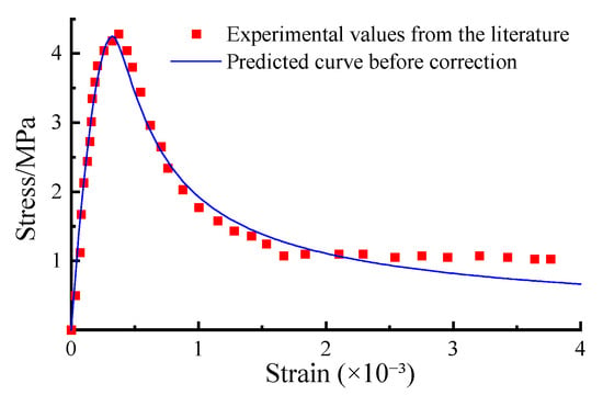
Figure 1.
Comparison Between the Modified Uniaxial Tensile Curve and Experimental Results.
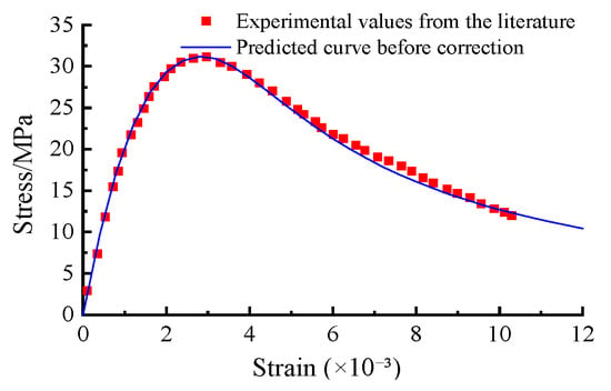
Figure 2.
Comparison between the modified uniaxial compressive curve and experimental results.
Using the damage variable from Najar’s theory, a comparative analysis was conducted among three commonly used concrete constitutive models available in ABAQUS 2023 (Dassault Systèmes, France) [16,24,25,26,27]. The results indicated that the Concrete Damage Plasticity (CDP) model more accurately captures the mechanical responses of concrete under uniaxial tension and uniaxial compression compared to the Brittle Failure Model and the Smeared Cracking Model. Therefore, this study selects the Concrete Damage Plasticity (CDP) model as the constitutive model for concrete.
Building upon the findings of multiple scholars [18,26,27,28,29] regarding the parameter selection for steel–polypropylene fiber-reinforced concrete, the fiber dosage and aspect ratio settings in this study were determined with reference to both existing standards and prior experimental results. Previous studies have suggested that the optimal steel fiber content should range between 0.5% and 2.0% by volume [26,27], while the Chinese Technical Specification for Fiber-Reinforced Concrete Structures (CECS 38:2004) recommends an aspect ratio between 30 and 80 [28]. For polypropylene fibers, dosage levels of 0.05%, 0.10%, and 0.15% were adopted based on the tensile test findings of Xu et al. [29], which indicated that polypropylene fiber geometry has a relatively minor effect compared with dosage. Accordingly, the parameters adopted for each working condition are summarized in Table 1.

Table 1.
Fiber parameters of steel–polypropylene fiber concrete.
In seismic joint design, foam concrete is frequently employed as a key material due to its lightweight nature, high strength, and notable energy absorption and deformation capabilities. Research by various teams on fiber-reinforced foam concrete has revealed that fiber incorporation significantly enhances tensile and compressive strength, elastic modulus, and properties such as drying shrinkage [30,31,32,33,34,35,36]. Consequently, crushable foam concrete with an elastic modulus of 0.375 GPa, a yield compressive stress ratio of 0.18, and a yield hydrostatic stress ratio of 0.003 was selected for the combined seismic joint design, working in conjunction with the steel–polypropylene fiber-reinforced concrete lining.
Referring to the material parameter settings proposed by Wang et al. [23] and considering the actual construction conditions of a separated double-track single-tube tunnel [33], frictional contact is established between the tunnel lining and surrounding rock. The Mohr-Coulomb constitutive model is adopted for the surrounding rock and fault fracture zone, with a friction coefficient of 0.6 for the surrounding rock and 0.5 for the sliding surface within the fault fracture zone. The secondary lining uses C30 concrete simulated by the Concrete Damage Plasticity (CDP) model. The initial support employs the Mohr-Coulomb model with the following parameters: C25 concrete, density 2400 kg/m3, elastic modulus 27.5 GPa, Poisson’s ratio 0.2, cohesion 12.5 MPa, and friction angle 51°. Detailed material parameters are summarized in Table 2.

Table 2.
Main material parameters.
Based on the mesoscopic damage evolution mechanism of hybrid fiber-reinforced concrete, the Najar energy method was employed to establish the quantitative relationship between damage variables and strain states. Taking working conditions 1 in Table 1 (steel fiber content: 0.5%, aspect ratio: 60; polypropylene fiber content: 0.1%, aspect ratio: 396) as an example, the key input parameters for the Concrete Damage Plasticity (CDP) model were derived through numerical iteration of damage evolution equations using MATLAB 2023a (The MathWorks, Natick, MA, USA). The complete compressive and tensile damage evolution curves are summarized in Table 3 and Table 4, respectively. Parameters for other cases were calculated following the same workflow.

Table 3.
CDP compressive input parameters (working conditions 1).

Table 4.
CDP tensile input parameters (working conditions 1).
2.2. Model Establishment
A separated double-tunnel model was constructed, with a tunnel width of 12.4 m and a height of 9.9 m, as illustrated in Figure 3. In accordance with Saint-Venant’s Principle, the boundary distance from the tunnel center was set to 3–5 times the tunnel diameter. Consequently, the model width was set to 100 m, and the distance from the bottom boundary to the tunnel bottom was set to 60 m, with a tunnel burial depth of 20 m, resulting in a total model height of approximately 90 m. During the meshing process, both the fault fracture zone and the surrounding rock near the tunnel lining were refined to enhance numerical accuracy. The longitudinal length of the model was set to 300 m. The tunnel lining comprises a primary support and a secondary lining, with thicknesses of 0.15 m and 0.35 m, respectively, resulting in a total lining thickness of 0.5 m. The final model and mesh division are depicted in Figure 3.
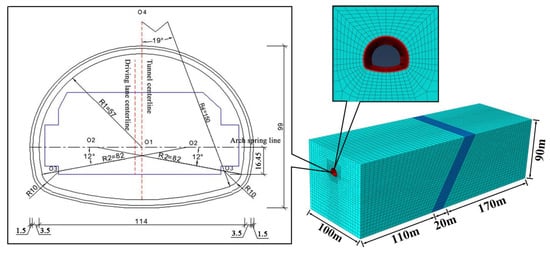
Figure 3.
Basic model and grid diagram.
2.3. Fault Movement Simulation
Referring to the empirical methods proposed by Sun et al. and Tao et al. [19,37], the simulation of reverse fault movement is conducted in three steps:
- Initial Geostress Equilibrium:
Normal constraints are applied to five surfaces, excluding the top free boundary, to ensure geostress equilibrium.
- 2.
- Tunnel Excavation:
The softening modulus method is employed to simulate the excavation process, which is performed in a single step to accurately represent the excavation process.
- 3.
- Fault Dislocation:
The top of the model is defined as a free boundary based on the fault movement simulation methodologies of Tao et al. and Qiu et al. [37,38], the top of the model is defined as a free boundary. A lateral displacement constraint aligned with the fault strike is applied, while normal displacement constraints are imposed longitudinally. The bottom of the hanging wall is subjected to normal constraints. Using the fault fracture zone center as the sliding interface, equal-magnitude but oppositely directed vertical and horizontal displacements are applied to the left and right bottom regions, simulating fault slip along the fracture zone center. The detailed boundary constraint settings for fault simulation are illustrated in Figure 4.
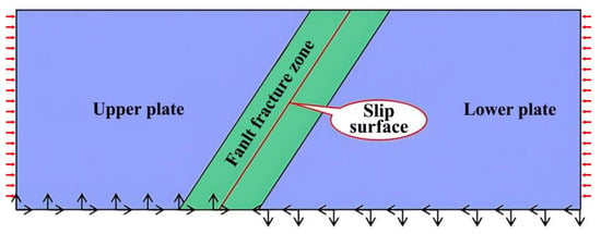
Figure 4.
Fault simulation constraint setting. (The black arrows indicate the applied boundary constraints, and the red arrows represent the direction of the fault displacement).
2.4. Model Validation
Following the construction of the model, a validation process was performed by simulating the fault movement test conducted by Qiu et al. [38]. The vertical displacement at the top of the tunnel lining was calculated using identical material parameters. As demonstrated in Figure 5, the simulation results show a strong correlation with the findings reported in the literature. The vertical displacement exhibited a characteristic Z-shaped pattern at the tunnel crown, consistent with the deformation mode observed in Qiu et al.’s [38] study. Minor discrepancies in displacement values can be attributed to the treatment of material self-weight and fault slip displacement as two distinct external loads in the simulation. These deviations are minimal and fall within an acceptable range, exerting no significant influence on the overall displacement pattern.
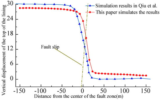
Figure 5.
Comparison of vertical displacement at the top of the lining [38].
To further ensure the reliability of the model under different geological conditions, the validation referred to Qiu et al. [38], who analyzed the Yuelongmen Tunnel crossing the Beichuan–Yingxiu fault under reverse fault dislocation using multiple working conditions, including fault dip angles of 30°, 45°, and 60°, and vertical displacements ranging from 10 to 50 cm. Their results demonstrated that reverse fault movement induces an “S”-shaped or “Z”-shaped longitudinal bending deformation in the tunnel lining, with opposite tensile and compressive stress distributions at the crown and invert, and that both the stress magnitude and vertical displacement increase with fault offset. The present model successfully reproduced these characteristic deformation and stress patterns, confirming that the constitutive model and boundary conditions adopted herein are dependable and applicable to tunnels subjected to varying fault geometries and geological configurations. In addition, a preliminary sensitivity analysis was performed to evaluate the influence of mesh refinement and boundary distance on the simulation results. Halving the element size produced less than a 3% variation in peak strain, while extending the boundary distance by 20% had negligible effects on the overall displacement and stress distribution. These findings confirm that the adopted mesh density and boundary settings provide adequate numerical stability for the present analysis.
2.5. Layout of Combined Seismic Joints
To simplify the analysis, fault displacement, fault dip angle, and tunnel burial depth were selected as the primary research variables. In the absence of a combined seismic joint design, preliminary calculations were conducted to evaluate the effects of varying fault displacements, dip angles, burial depths, and hybrid fiber parameters on the maximum principal stress at the tunnel crown, spandrel, and arch foot. The results showed that when the fault displacement increases to about 30 cm, the hybrid fiber reinforcement significantly improves the bearing capacity at the arch crown and foot, but beyond this threshold the growth of reinforcement efficiency decreases as the lining approaches its stress limit. Further analyses indicated that a vertical fault displacement of 40 cm, with a 60° dip angle and a 20 m burial depth, represents a critical condition under which tunnel damage becomes pronounced and the influence of material parameters is most evident. Therefore, this displacement magnitude was selected as the representative case for subsequent analysis of the combined seismic joint and fiber-reinforced liner design. Under these conditions, the maximum principal stress distribution cloud diagram caused by reverse fault displacement is presented in Figure 6.

Figure 6.
Longitudinal distribution of maximum principal stress in secondary lining.
Analysis of Figure 6 reveals that the impact of reverse fault movement on the maximum principal stress of the tunnel lining is concentrated within an 80 m range around the fault slip zone. Referring to the quantitative design formula for tunnel combined seismic joints proposed by Sun’s research team [19], densified combined seismic joints should be strategically arranged within this 80 m range of the fault fracture zone and its adjacent areas. To mitigate structural performance variations, a transition zone should be established over a defined length near the densified area. The specific arrangement of these seismic joints is illustrated in Figure 7.

Figure 7.
Seismic joint layout design when the displacement is 40 cm.
3. Analysis of Seismic Performance of Combined Seismic Joints and Steel–Polypropylene Fiber Lining in the Tunnel
In this section, the vertical fault displacement is set to 40 cm, and the working conditions established in Section 2.1 are applied. By controlling the combined seismic joint conditions, the strain distribution cloud diagram of the tunnel lining is analyzed. The influence of the combined layout of steel–polypropylene fiber concrete and combined seismic joints on the fault-resistance performance of the tunnel is evaluated from three perspectives: longitudinal strain, plastic strain, and tensile-compressive damage. This analysis aims to investigate improvements in overall deformation, energy dissipation, and damage characteristics of the tunnel structure.
3.1. Longitudinal Strain Analysis
3.1.1. Effect of Different Polypropylene Fiber Content
By maintaining the steel fiber content and aspect ratio at 1.2% and 60, respectively, and adjusting the polypropylene fiber content (ρpf) from 0.05% to 0.10%, and finally to 0.15%, along with controlling the presence or absence of seismic joint arrangements, the longitudinal strain extremes of the tunnel lining near the fault dislocation zone were calculated. The longitudinal strain distribution patterns can be referred to in Figure 8a,b, where (a) and (b) correspond to working conditions 5 and 12, respectively.
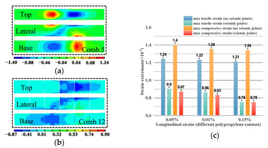
Figure 8.
Longitudinal strain under different polypropylene fiber contents. (a) working conditions 5. (b) working conditions 12. (c) Changes in Longitudinal Strain Extremes for Working Conditions 5 and 12.
By observing the changes in the longitudinal strain extremes shown in Figure 8c, it can be concluded that as the value of ρpf increases from 0.05% to 0.15%, the introduction of seismic joints results in a reduction in the maximum compressive strain in the tunnel lining by 37.8%, 38.5%, and 40.3%, respectively, compared to conditions without seismic joints. Similarly, the maximum tensile strain is reduced by 27.4%, 30.1%, and 38.1%, respectively.
When ρpf increases from 0.05% to 0.15%, the improvement in the suppression effect on the maximum compressive strain due to the presence of seismic joints, compared to conditions without seismic joints, is 13.8% and 4.3%, respectively. For the tensile strain, the improvement in suppression effectiveness is 16.7% and 2.4%, respectively.
3.1.2. Different Steel Fiber Contents
By maintaining the aspect ratio of steel fibers and the polypropylene fiber content at 60 and 0.1%, respectively, and adjusting the steel fiber content (ρsf) from 0.5% to 1.2%, and finally to 1.9%, along with controlling the presence or absence of seismic joints, the maximum longitudinal strain of the tunnel lining near the fault dislocation zone was calculated. The longitudinal strain distribution can be referred to in Figure 9a,b, where (a) corresponds to Working Condition 1 and (b) corresponds to Working Condition 8.
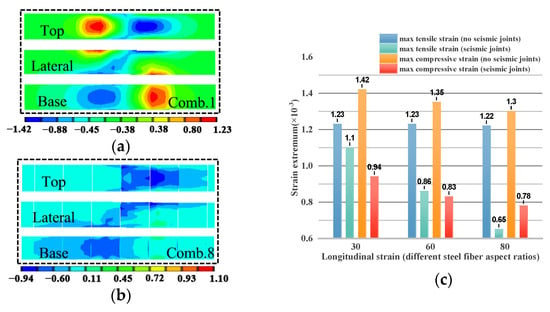
Figure 9.
Longitudinal strain under different steel fiber contents. (a) Working Condition 1. (b) Working Condition 8. (c) Changes in Longitudinal Strain Extremes for Working Conditions 1 and 8.
By observing the changes in the longitudinal strain extremes shown in Figure 9c, it can be concluded that as ρsf increases from 0.5% to 1.9%, the introduction of seismic joints results in a reduction in the maximum compressive strain of the tunnel lining by 9.7%, 30.1%, and 39.2%, respectively, compared to scenarios without seismic joints. Similarly, the maximum tensile strain is reduced by 35.7%, 38.5%, and 39.2%, respectively.
When ρsf increases from 0.5% to 1.9%, the improvement in the suppression effect on the maximum compressive strain due to the presence of seismic joints, compared to conditions without seismic joints, is 12.2% and 7.1%, respectively. For tensile strain, the improvement in suppression effectiveness is 25.9% and 1.6%, respectively.
3.1.3. Different Steel Fiber Aspect Ratios
By maintaining the steel fiber content and polypropylene fiber content at 0.5% and 0.1%, respectively, and adjusting the steel fiber aspect ratio (lsf/dsf) from 30 to 60, and finally to 80, while controlling the presence or absence of seismic joints, the maximum longitudinal strain of the tunnel lining near the fault dislocation zone was calculated. The longitudinal strain distribution can be seen in Figure 10a,b, where (a) corresponds to Working Condition 6 and (b) corresponds to Working Condition 13.
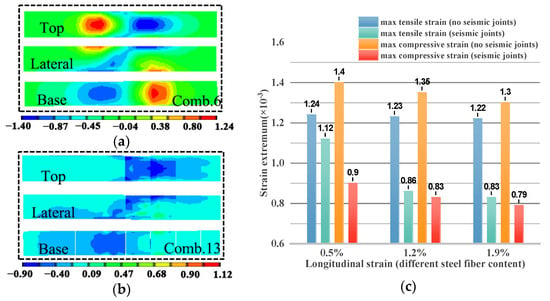
Figure 10.
Longitudinal strain under different steel fiber aspect ratios. (a) Working Condition 6. (b) Working Condition 13. (c) Changes in Longitudinal Strain Extremes for Working Conditions 6 and 13.
By analyzing the changes in the longitudinal strain extremes shown in Figure 10c, it can be concluded that as lsf/dsf increases from 30 to 80, the introduction of seismic joints results in a reduction in the maximum tensile strain damage to the tunnel lining by 10.6%, 30.1%, and 46.7%, respectively, compared to scenarios without seismic joints. Similarly, the maximum compressive strain is reduced by 33.8%, 38.5%, and 40.1%, respectively.
When lsf/dsf increases from 30 to 80, the improvement in the suppression effect on the maximum compressive strain due to the presence of seismic joints, compared to conditions without seismic joints, is 17% and 8.5%, respectively. For tensile strain, the improvement in suppression effectiveness is 40.9% and 0.8%, respectively.
3.2. Plastic Strain Analysis
3.2.1. Different Polypropylene Fiber Contents
By maintaining the steel fiber content at 1.2% and an aspect ratio of 60, while adjusting the polypropylene fiber content (ρpf) from 0.05% to 0.10%, and finally to 0.15%, and controlling the presence or absence of combined seismic joints, the peak plastic strain of tunnel linings near the fault dislocation zone is calculated. Figure 11a,b present the cloud maps of the compressive plastic zones, while Figure 11c,d show the cloud maps of the tensile plastic zones. Figure 11a,c correspond to Working Condition 5, and Figure 11b,d correspond to Working Condition 12.
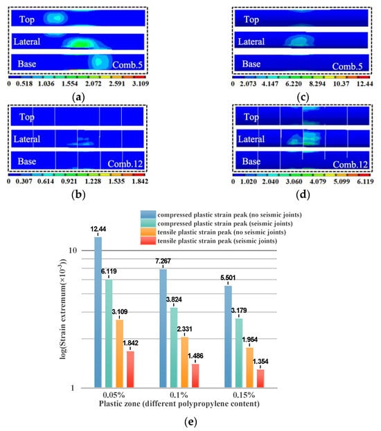
Figure 11.
Plastic strain under different polypropylene fiber contents. (a) Working Condition 5. (b) Working Condition 12. (c) Working Condition 5. (d) Working Condition 12. (e) Variation in peak plastic strain.
By observing the variation in peak plastic strain in Figure 11e, it can be concluded that as ρpf increases from 0.05% to 0.15%, with the addition of combined seismic joints, the peak compressive plastic strain of the tunnel lining decreases by 50.8%, 47.7%, and 42.2%, respectively, compared to scenarios without combined seismic joints. Similarly, the peak tensile plastic strain decreases by 40.8%, 36.3%, and 30.7%, respectively. As ρpf increases from 0.05% to 0.15%, the suppression effect on peak compressive plastic strain under Working Conditions 5 and 12 improves by 48.1% and 55.8%, respectively, while the suppression effect on peak tensile plastic strain improves by 26.5% and 37.2%, respectively.
3.2.2. Different Steel Fiber Contents
By maintaining a steel fiber aspect ratio of 60 and a polypropylene fiber content of 0.1%, while adjusting the steel fiber content (ρsf) from 0.5% to 1.2%, and then to 1.9%, and controlling the presence or absence of combined seismic joints, the extreme values of the damage factor for tunnel linings near the fault dislocation zone are calculated. Figure 12a,b display the cloud maps of the compressive damage zones, while Figure 12c,d show the cloud maps of the tensile damage zones. Figure 12a,c correspond to Working Condition 1, and Figure 12b,d correspond to Working Condition 8.
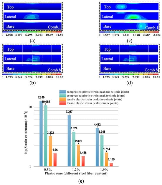
Figure 12.
Plastic strain under different steel fiber contents. (a) Working Condition 1. (b) Working Condition 8. (c) Working Condition 1. (d) Working Condition 8. (e) Variation in peak plastic strain.
By observing the variation in peak plastic strain in Figure 12e, it can be concluded that as ρsf increases from 0.5% to 1.9%, with the addition of combined seismic joints, the peak compressive plastic strain of the tunnel lining decreases by 15.4%, 47.4%, and 24.2%, respectively, compared to scenarios without combined seismic joints. Similarly, the peak tensile plastic strain decreases by 48.5%, 36.3%, and 33.2%, respectively. As ρsf increases from 0.5% to 1.9%, the suppression effect on peak compressive plastic strain under Working Conditions 1 and 8 improves by 68.6% and 64.9%, respectively, while the suppression effect on peak tensile plastic strain improves by 31% and 46.8%, respectively.
3.2.3. Different Steel Fiber Length-to-Diameter Ratios
By maintaining the steel fiber content and polypropylene fiber content at 0.5% and 0.1%, respectively, while adjusting the steel fiber length-to-diameter ratio (lsf/dsf) from 30 to 60, and then to 80, and controlling the presence or absence of combined seismic joints, the extreme values of the damage factor for tunnel linings near the fault dislocation zone are calculated. Figure 13a,b display the cloud maps of the compressive damage zones, while Figure 13c,d show the cloud maps of the tensile damage zones. Figure 13a,c correspond to Working Condition 6, and Figure 13b,d correspond to Working Condition 13.
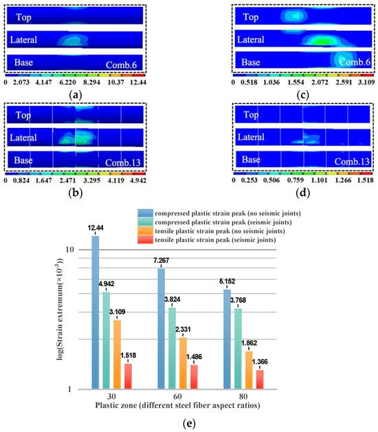
Figure 13.
Plastic strain under different steel fiber length-to-diameter ratios. (a) Working Condition 6. (b) Working Condition 13. (c) Working Condition 6. (d) Working Condition 13. (e) Variation in peak plastic strain.
By observing the variation in peak plastic strain in Figure 13e, it can be concluded that as the lsf/dsf ratio increases from 30 to 80, with the addition of combined seismic joints, the peak compressive plastic strain of the tunnel lining decreases by 60.3%, 47.4%, and 26.9%, respectively, compared to scenarios without combined seismic joints. Similarly, the peak tensile plastic strain decreases by 51.1%, 36.3%, and 26.6%, respectively. As the lsf/dsf ratio increases from 30 to 80, the suppression effect on peak compressive plastic strain under Working Conditions 6 and 13 improves by 23.8% and 58.6%, respectively, while the suppression effect on peak tensile strain improves by 10% and 40.1%, respectively.
3.3. Tensile and Compressive Damage Analysis
3.3.1. Different Polypropylene Fiber Contents
By maintaining the steel fiber content at 1.2% and an aspect ratio of 60, while adjusting the polypropylene fiber content (ρpf) from 0.05% to 0.10%, and then to 0.15%, and controlling the presence or absence of combined seismic joints, the extreme values of the damage factor for tunnel linings near the fault dislocation zone are calculated. Figure 14a,b display the cloud maps of the compressive damage zones, while Figure 14c,d show the cloud maps of the tensile damage zones. Figure 14a,c correspond to Working Condition 5, and Figure 14b,d correspond to Working Condition 12.
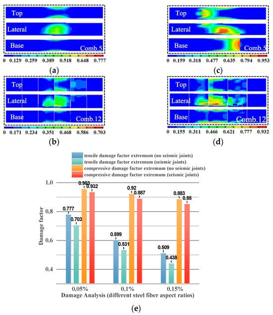
Figure 14.
Tensile and compressive damage under different polypropylene fiber contents. (a) Working Condition 5. (b) Working Condition 12. (c) Working Condition 5. (d) Working Condition 12. (e) Variation in extreme values of the damage factor.
By observing the variation in the extreme values of the damage factor in Figure 14e, it can be concluded that as ρpf increases from 0.05% to 0.15%, with the addition of combined seismic joints, the extreme values of the compressive damage factor of the tunnel lining decrease by 9.5%, 11.4%, and 13.6%, respectively, compared to scenarios without combined seismic joints. Similarly, the extreme values of the tensile damage factor decrease by 2.2%, 3.6%, and 3.7%, respectively. Further analysis indicates that as ρpf increases from 0.05% to 0.15%, the suppression effect on the extreme values of the compressive damage factor under Working Conditions 5 and 12 improves by 37.7% and 34.5%, respectively, while the suppression effect on the extreme values of the tensile damage factor improves by 8.8% and 16.7%, respectively.
3.3.2. Different Steel Fiber Contents
By maintaining a steel fiber aspect ratio of 60 and a polypropylene fiber content of 0.1%, while adjusting the steel fiber content (ρsf) from 0.5% to 1.2%, and then to 1.9%, and controlling the presence or absence of combined seismic joints, the extreme values of the damage factor for tunnel linings near the fault dislocation zone are calculated. Figure 15a,b display the cloud maps of the compressive damage zones, while Figure 15c,d show the cloud maps of the tensile damage zones. Figure 15a,c correspond to Working Condition 1, and Figure 15b,d correspond to Working Condition 8.
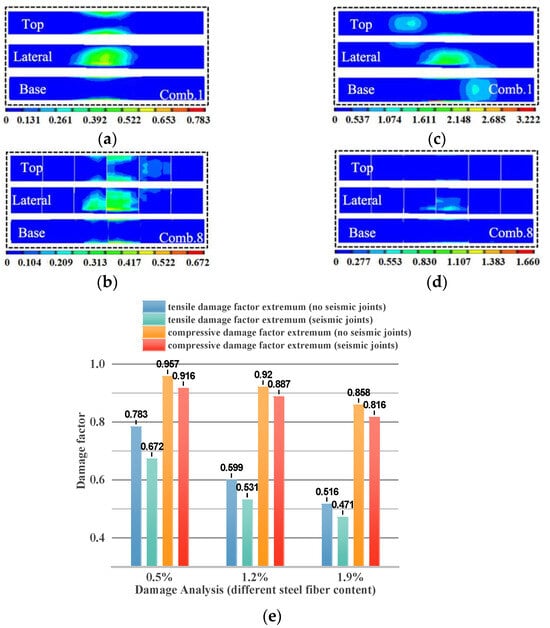
Figure 15.
Tensile and compressive damage under different steel fiber contents. (a) Working Condition 1. (b) Working Condition 8. (c) Working Condition 1. (d) Working Condition 8. (e) Variation in extreme values of the damage factor.
By observing the variation in the extreme values of the damage factor in Figure 15e, it can be concluded that as ρsf increases from 0.5% to 1.9%, with the addition of combined seismic joints, the extreme values of the compressive damage factor of the tunnel lining decrease by 14.2%, 11.4%, and 8.7%, respectively, compared to scenarios without combined seismic joints. Similarly, the extreme values of the tensile damage factor decrease by 4.3%, 3.6%, and 4.9%, respectively. Further analysis indicates that as ρsf increases from 0.5% to 1.9%, the suppression effect on the extreme values of the compressive damage factor under Working Conditions 1 and 8 improves by 12.2% and 34.1%, respectively, while the suppression effect on the extreme values of the tensile damage factor improves by 10.9% and 29.9%, respectively.
3.3.3. Different Steel Fiber Length-to-Diameter Ratios
By maintaining the steel fiber content at 0.5% and the polypropylene fiber content at 0.1%, while adjusting the steel fiber length-to-diameter ratio (lsf/dsf) from 30 to 60, and then to 80, and controlling the presence or absence of combined seismic joints, the extreme values of the damage factor for tunnel linings near the fault dislocation zone are calculated. Figure 16a,b display the cloud maps of the compressive damage zones, while Figure 16c,d show the cloud maps of the tensile damage zones. Figure 16a,c correspond to Working Condition 6, and Figure 16b,d correspond to Working Condition 13.
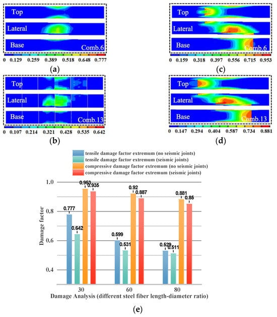
Figure 16.
Tensile and compressive damage under different steel fiber length-to-diameter ratios. (a) Working Condition 6. (b) Working Condition 13. (c) Working Condition 6. (d) Working Condition 13. (e) Variation in extreme values of the damage factor.
By observing the variation in the extreme values of the damage factor in Figure 16e, it can be concluded that as the lsf/dsf ratio increases from 30 to 80, with the addition of combined seismic joints, the extreme values of the compressive damage factor of the tunnel lining decrease by 17.3%, 11.4%, and 3.4%, respectively, compared to scenarios without combined seismic joints. Similarly, the extreme values of the tensile damage factor decrease by 1.9%, 3.6%, and 3.5%, respectively. Further analysis indicates that as the lsf/dsf ratio increases from 30 to 80, the suppression effect on the extreme values of the compressive damage factor under Working Conditions 6 and 13 improves by 17% and 31.9%, respectively, while the suppression effect on the extreme values of the tensile damage factor improves by 9.1% and 20.4%, respectively.
4. Results
4.1. Strain Distribution in Tunnel Linings
Numerical simulations show that the integrated design of steel–polypropylene fiber (SPF) concrete linings with combined seismic joints effectively suppresses extreme tensile and compressive strains in tunnel linings subjected to a vertical fault displacement of 40 cm.
- (1)
- Influence of polypropylene fiber content (ρpf): With the steel fiber content and aspect ratio fixed at 1.2% and 60, respectively, increasing ρpf from 0.05% to 0.15% resulted in maximum reductions in compressive strain of 37.8–40.3% and tensile strain of 27.4–38.1%.Statistical Analysis: Variations exceeding 10% in compressive and tensile strains were considered practically significant, confirming the robustness of the observed trends.
- (2)
- Influence of steel fiber content (ρsf): With ρpf = 0.1% and aspect ratio 60, increasing ρsf from 0.5% to 1.9% reduced compressive strain by 9.7–39.2% and tensile strain by 35.7–39.2%.Statistical Analysis: One-way ANOVA showed that the reductions in both compressive and tensile strains were statistically significant (p < 0.05).
- (3)
- Influence of steel fiber aspect ratio (lsf/dsf): With ρsf = 0.5% and ρpf = 0.1%, increasing the aspect ratio from 30 to 80 reduced tensile strain by 10.6–46.7% and compressive strain by 33.8–40.1%.Statistical Analysis: Variations exceeding 10% in tensile and compressive strain were considered significant, further validating the findings.
4.2. Plastic Zone Characteristics
The combined design markedly decreased the peak plastic strain and promoted a more uniform plastic zone distribution.
- (1)
- Increasing ρpf from 0.05% to 0.15% lowered peak compressive plastic strain by 42.2–50.8% and tensile plastic strain by 30.7–40.8%.Statistical Analysis: Variations greater than 10% were considered statistically significant, confirming the effectiveness of fiber reinforcement.
- (2)
- Increasing ρsf from 0.5% to 1.9% lowered peak compressive plastic strain by 15.4–47.4% and tensile plastic strain by 33.2–48.5%.Statistical Analysis: The reductions in plastic strain were statistically significant (p < 0.05), confirming the strong effect of steel fibers.
- (3)
- Increasing lsf/dsf from 30 to 80 lowered peak compressive plastic strain by 26.9–60.3% and tensile plastic strain by 26.6–51.1%.Statistical Analysis: This reduction was found to be statistically significant (p < 0.05).
4.3. Tensile and Compressive Damage
The combined measures reduced both tensile and compressive damage factors, with a stronger effect on compressive damage.
- (1)
- Increasing ρpf to 0.15% decreased the compressive damage factor by up to 13.6% and the tensile damage factor by up to 3.7%.Statistical Analysis: The reduction in compressive damage was statistically significant (p < 0.05).
- (2)
- Increasing ρsf to 1.9% decreased compressive damage by 8.7–14.2% and tensile damage by 3.6–4.9%.Statistical Analysis: The reductions in damage were statistically significant (p < 0.05), particularly at higher ρsf.
- (3)
- Increasing lsf/dsf to 80 decreased compressive damage by 3.4–17.3% and tensile damage by 1.9–3.5%.Statistical Analysis: The reduction in both tensile and compressive damage was statistically significant (p < 0.05).
5. Discussion
This study demonstrates that the synergistic combination of steel–polypropylene fiber concrete and seismic joints substantially enhances the fault-resistance performance of tunnel linings.
First, the marked reduction in extreme tensile and compressive strains confirms the dual role of the integrated design:
- (1)
- Fibers increase matrix toughness and bridge cracks, delaying both tensile and compressive failure;
- (2)
- Seismic joints redistribute stress concentrations and provide additional deformation capacity.
These findings are consistent with earlier model tests and analytical studies that highlighted the importance of combining material strengthening and structural flexibility in fault-fracture zones.
Second, the significant reduction and homogenization of the plastic zone reveal that the combined measures not only strengthen the lining but also improve energy-dissipation capacity. The 60.3% reduction in peak compressive plastic strain under Working Condition 13 illustrates the enhanced ability to accommodate large displacements without localized damage, an outcome not achievable by fiber reinforcement alone, as suggested in previous studies.
Third, the results show that compressive damage is more effectively suppressed than tensile damage. This trend reflects the high crack-bridging capacity of steel fibers under compression and the ability of polypropylene fibers to restrain microcrack propagation. Nevertheless, as fiber dosage increases, the incremental benefit of seismic joints diminishes, implying an upper limit of synergy. Optimal design therefore requires a balanced combination of fiber content and joint spacing rather than simply maximizing any single parameter.
Limitations
The identified optimal parameters are specific to the conditions analyzed in this study and should be recalibrated for other geological settings or tunnel geometries. In addition, the numerical model involved certain simplifications, including idealized rock–lining interaction and boundary conditions, and it did not account for dynamic seismic effects, which may influence the accuracy of strain and damage predictions. Future studies should incorporate more realistic boundary conditions, dynamic loading, and field validation to enhance model reliability.
Overall, these findings provide a mechanistic explanation for the observed improvements in tunnel fault resistance and underline the need for integrated design strategies in seismic and fault-prone regions.
6. Conclusions
This study investigated the seismic performance of tunnel linings reinforced by steel–polypropylene fiber concrete in combination with seismic joints under a 40 cm vertical fault displacement. The main conclusions are as follows:
- (1)
- Strain suppression: The integrated design reduced longitudinal tensile and compressive strains by up to 40.1% and 46.7%, respectively, compared with fiber reinforcement alone.
- (2)
- Plastic zone optimization: Peak compressive plastic strain decreased by as much as 60.3%, producing a more uniform strain distribution and improved deformation capacity.
- (3)
- Damage mitigation: Tensile and compressive damage factors decreased by up to 4.9% and 17.3%, respectively, with a more pronounced effect on compressive damage.
- (4)
- Optimal parameters: The best fault-resistance performance was achieved at 1.90% steel fiber content, an aspect ratio of 60, and 0.15% polypropylene fiber content.
- (5)
- Engineering implication: The combined use of seismic joints and SPF concrete linings provides a flexible and durable solution for tunnels crossing fault-fracture zones, ensuring long-term structural stability and service life.
- (6)
- Practical applicability and broader implementation.
Under a 40 cm fault displacement, the integrated design reduced the maximum compressive strain by about 45% and the plastic zone area by over 50% compared with conventional linings. The optimal mix—1.9% steel fiber and 0.15% polypropylene fiber—falls within practical construction ranges, demonstrating strong engineering feasibility, cost-effectiveness, and potential for widespread application in tunnels across fault zones.
Author Contributions
Conceptualization, Y.W.; methodology, Y.W.; software, Z.Y.; validation, R.W., B.D., and Z.W.; formal analysis, Z.Y.; investigation, R.W., B.D., and Z.W.; resources, B.D. and Z.W.; data curation, B.D. and Z.W.; writing—original draft preparation, Y.W. and Z.Y.; writing—review and editing, R.W.; visualization, Z.Y.; supervision, Y.W.; project administration, Y.W.; funding acquisition, Y.W. All authors have read and agreed to the published version of the manuscript.
Funding
This research was funded by the National Natural Science Foundation of China, grant numbers 51778633 and 51308552.
Data Availability Statement
The original contributions presented in this study are included in the article. Further inquiries can be directed to the corresponding author.
Conflicts of Interest
The authors declare no conflicts of interest.
References
- Ding, X.; Feng, L.; Wang, C.; Chen, Z.; Han, L. Shaking table tests of the seismic response of a utility tunnel with a joint connection. Soil Dyn. Earthq. Eng. 2020, 133, 106133. [Google Scholar] [CrossRef]
- Tsinidis, G.; Rovithis, E.; Pitilakis, K.; Chazelas, J.L. Seismic response of box-type tunnels in soft soil: Experimental and numerical investigation. Tunn. Undergr. Space Technol. 2016, 59, 199–214. [Google Scholar] [CrossRef]
- Yao, C.; Duan, J.; Liu, Y.; He, C.; Liu, Y.; Yang, W.; Yan, Q.; Luo, W. Tunnels crossing active faults: A review of case histories and modeling methods. Tunn. Undergr. Space Technol. 2025, 157, 107086. [Google Scholar] [CrossRef]
- Liu, X.; Zhang, C.; Xiao, H.; Zhou, H.; Chi, F. Deformation and failure characteristics of a deeply buried tunnel subjected to creep slip fault movement: Based on the engineering conditions of Yunnan Water Intake Project. Bull. Eng. Geol. Environ. 2022, 81, 322. [Google Scholar] [CrossRef]
- Zhang, Y.; Zhang, Z.; Yin, C.; Wei, R.; Zhang, H. Experimental study on forced response characteristics and anti-dislocation performance of articulated tunnel structure under dislocation action of normal fault. Structures 2023, 48, 867–881. [Google Scholar] [CrossRef]
- Zhao, Y.; Guo, E.D.; Liu, Z.; Gao, L. Damage analysis of urban metro tunnel under strike-slip fault. Rock Soil Mech. 2014, 35 (Suppl. S2), 467–473. (In Chinese) [Google Scholar]
- Hu, H.; Liu, Y.; Lan, Y.; Zhang, H.; Qiu, W. Study on Failure Characteristics and Treatment of Tunnel Lining Crossing Active Faults. Transp. Res. Rec. 2025, 2679, 03611981251337673. [Google Scholar] [CrossRef]
- Mei, X.; Xu, W.; Zhang, L.; Li, Y. The response characteristics of fault-crossing tunnel under combined fault slip and seismic loading. Soil Dyn. Earthq. Eng. 2025, 198, 109653. [Google Scholar] [CrossRef]
- Zhao, F.; Liang, B.; Zhao, N.; Jiang, B. Shaking table testing and numerical study on aseismic measures of twin-tube tunnel crossing fault zone with extra-large section. Appl. Sci. 2024, 14, 2391. [Google Scholar] [CrossRef]
- Cui, G.Y.; Song, B.H.; Wang, D.Y. Seismic model test research on the combination of rigidity with flexibility of tunnel portal in high intensity seismic areas. Geomatics Nat. Hazards Risk 2021, 12, 1195–1211. [Google Scholar] [CrossRef]
- Cheng, Z.; Su, Y.; Xu, C. Seismic Response of Mountain Tunnels by Comprehensive Analysis Methods and Feasible Aseismic Measures. Highlights Sci. Eng. Technol. 2022, 28, 31–44. [Google Scholar] [CrossRef]
- Anastasopoulos, I.; Gerolymos, N.; Drosos, V.; Georgarakos, T.; Kourkoulis, R.; Gazetas, G. Behaviour of deep immersed tunnel under combined normal fault rupture deformation and subsequent seismic shaking. Bull. Earthq. Eng. 2008, 6, 213–239. [Google Scholar] [CrossRef]
- Soe, K.T.; Zhang, Y.X.; Zhang, L.C. Material properties of a new hybrid fibre-reinforced engineered cementitious composite. Constr. Build. Mater. 2013, 43, 399–407. [Google Scholar] [CrossRef]
- Qian, C.X.; Stroeven, P. Development of hybrid polypropylene–steel fibre-reinforced concrete. Cem. Concr. Res. 2000, 30, 63–69. [Google Scholar] [CrossRef]
- Hosseinzadeh, H.; Salehi, A.M.; Mehraein, M.; Asadollahfardi, G. The effects of steel, polypropylene, and high-performance macro polypropylene fibers on mechanical properties and durability of high-strength concrete. Constr. Build. Mater. 2023, 386, 131589. [Google Scholar] [CrossRef]
- Chi, Y.; Xu, L.; Yu, H.S. Constitutive modeling of steel–polypropylene hybrid fiber reinforced concrete using a non-associated plasticity and its numerical implementation. Compos. Struct. 2014, 111, 497–509. [Google Scholar] [CrossRef]
- Kotoky, N.; Dutta, A.; Deb, S.K. Mechanical properties of hybrid fiber reinforced concrete with steel and polypropylene fibers. Indian Concr. J. 2020, 94, 29–37. [Google Scholar]
- Wang, L.; Cui, G.; Zhang, C.; Zhao, Y.; Ma, J.; Min, B. Failure characteristics and seismic behavior of steel-basalt hybrid fiber reinforced concrete lining for the tunnel in strong earthquake areas. Eng. Fail. Anal. 2024, 162, 108357. [Google Scholar] [CrossRef]
- Sun, F.B.; Zhao, B.M.; Yang, Q.Y. Calculation formula and test verification for quantitative setting of combined seismic joint for tunnel through active fault. Chin. Railw. Sci. 2018, 39, 61–70. (In Chinese) [Google Scholar]
- Shen, Y.S.; Wang, Z.Z.; Yu, J.; Zhang, X.; Gao, B. Shaking table test on flexible joints of mountain tunnels passing through normal fault. Tunn. Undergr. Space Technol. 2020, 98, 103299. [Google Scholar] [CrossRef]
- Li, J.; Luo, J.; Chen, L.; Fan, X.; Zhu, Y.; Wang, X.; Guo, J. Research on mechanical properties of steel–polypropylene fiber concrete and application of beam structure. Front. Mater. 2024, 11, 1440466. [Google Scholar] [CrossRef]
- Zhou, M.; He, X.; Wang, H.; Wu, C.; He, J.; Wei, B. Mechanical properties and microstructure of ITZs in steel and polypropylene hybrid fiber-reinforced concrete. Constr. Build. Mater. 2024, 415, 135119. [Google Scholar] [CrossRef]
- Wang, S.; Xu, L.; Li, B.; Liu, S.; Chi, Y. Mechanical behavior and stress–strain model of steel-polypropylene hybrid fiber reinforced ultra-high performance concrete under triaxial compression. Constr. Build. Mater. 2024, 450, 138595. [Google Scholar] [CrossRef]
- Yang, M.; Huang, C.K. Study on stress–strain curve of high-strength steel fiber reinforced concrete under uniaxial tension. Chin. Civ. Eng. J. 2006, 39, 55–61. (In Chinese) [Google Scholar]
- Shi, X.; Park, P.; Rew, Y.; Huang, K.; Sim, C. Constitutive behaviors of steel fiber reinforced concrete under uniaxial compression and tension. Constr. Build. Mater. 2020, 233, 117316. [Google Scholar] [CrossRef]
- Cui, G.; Ma, J. Structure strengthening method for enhancing seismic behavior of soft tunnel portal section. Math. Probl. Eng. 2021, 2021, 6624963. [Google Scholar] [CrossRef]
- Wang, H.; Chen, Y.; Ding, Q.; Zhang, C. Influence of hybrid fibers on the mechanical and impermeability properties of high-performance concrete. Concr. Cem. Prod. 2004, 1, 38–40. (In Chinese) [Google Scholar]
- Huang, C. Introduction to Technical Specification for Fiber-Reinforced Concrete Structures (CECS38:2004). Eng. Constr. Stand. 2005, 5, 5. (In Chinese) [Google Scholar]
- Xu, L.; Mei, G.; Huang, L.; Lu, W. Study on uniaxial tensile stress–strain relationship of steel–polypropylene hybrid fiber reinforced concrete. China Civ. Eng. J. 2014, 47, 35–45. (In Chinese) [Google Scholar]
- Najar, J. A theory of concrete damage. Int. J. Solids Struct. 1987, 23, 451–469. [Google Scholar]
- Lei, Z. A modified constitutive model for concrete. J. Struct. Eng. 1996, 122, 1126–1134. [Google Scholar]
- Wang, Z.Q. Energy damage theory for fiber-reinforced concrete. Cem. Concr. Compos. 2004, 26, 397–402. [Google Scholar]
- Jasim, B.W.; Al-Gasham, T.S. Hybrid fiber reinforced concrete–A review of recent progress. Case Stud. Constr. Mater. 2022, 17, e01341. [Google Scholar] [CrossRef]
- Reddy, K.C.; Gudur, C.; Subramaniam, K.V.L. Study on the influences of silica and sodium in the alkali-activation of ground granulated blast furnace slag. Constr. Build. Mater. 2020, 257, 119514. [Google Scholar] [CrossRef]
- Wu, S.; Zhang, W.; Zhang, Y.; Wang, C. Arresting Properties of Polypropylene Fiber-Reinforced Foamed Concrete Under Wet-Dry Cycles. Constr. Build. Mater. 2024, 427, 136233. [Google Scholar] [CrossRef]
- Dhanalakshmi, A.; Shahul Hameed, M.A.; Jeyaseela, J.; Karthika, S. Study on the Performance Behaviour of Fibre Reinforced Foam Concrete. Mater. Sci. Forum 2024, 1120, 127–136. [Google Scholar] [CrossRef]
- Tao, Z.; Mao, Y.; Sun, J.; Zhang, X.; Huo, S.; He, M. Research on Energy-Absorption Active Control Method for Large Deformation of Tunnel Surrounding Rock through Multi-Fault Fracture Zone. Can. Geotech. J. 2024, 61, 1977–1995. [Google Scholar] [CrossRef]
- Qiu, Z.W.; Yu, Y.; Du, Y.; Zhou, Z.H. Numerical Simulation of the Impact of Reverse Fault Displacement on Tunnel Engineering. J. Seismol. Res. 2021, 43, 237–244. (In Chinese) [Google Scholar]
Disclaimer/Publisher’s Note: The statements, opinions and data contained in all publications are solely those of the individual author(s) and contributor(s) and not of MDPI and/or the editor(s). MDPI and/or the editor(s) disclaim responsibility for any injury to people or property resulting from any ideas, methods, instructions or products referred to in the content. |
© 2025 by the authors. Licensee MDPI, Basel, Switzerland. This article is an open access article distributed under the terms and conditions of the Creative Commons Attribution (CC BY) license (https://creativecommons.org/licenses/by/4.0/).