Article

Numerical Study on the Flexural Performance of Fully Bolted Joint for Panelized Steel Modular Structure

1
College of Civil Engineering, Tianjin Chengjian University, Tianjin 300384, China
2
Tianjin Key Laboratory of Civil Structure Protection and Reinforcement, Tianjin 300384, China
3
School of Civil Engineering, Tianjin University, Tianjin 300072, China
4
China MCC22 Group Co., Ltd., Tangshan 063000, China
*
Author to whom correspondence should be addressed.
Buildings 2025, 15(20), 3807; https://doi.org/10.3390/buildings15203807
Submission received: 29 September 2025 / Revised: 15 October 2025 / Accepted: 20 October 2025 / Published: 21 October 2025

Abstract

To investigate the initial rotational stiffness and ultimate moment of fully bolted connections in panelized steel modular structures, a finite element analysis was carried out on 20 joint models. High-fidelity models were developed using ABAQUS, and their accuracy was confirmed through comparison with experimental tests. A parametric study was performed to systematically evaluate the effects of the column wall thickness in the core zone, internal diaphragm configurations, angle steel thickness, and stiffener layouts on the joint stiffness and ultimate strength, leading to practical optimization suggestions. Additionally, a mechanical model and a corresponding formula for predicting the initial rotational stiffness of the joints were proposed based on the component method in Eurocode EC3. The model was validated against the finite element results, showing good reliability. Three failure modes were identified as follows: buckling deformation of the beam flange, buckling deformation of the column flange, and deformation of the joint panel zone. In joints with a weak core zone, both the use of internal diaphragms and increased column wall thickness effectively improved the initial rotational stiffness and ultimate bearing capacity. For joints with weak angle steel connections, adding stiffeners or increasing the limb thickness significantly enhanced both the stiffness and capacity. The diameter of bolts in the endplate-to-column flange connection was found to have a considerable effect on the initial rotational stiffness, but minimal impact on the ultimate strength. This study offers a theoretical foundation for the engineering application of panelized steel modular structural joints.

1. Introduction

Modular construction is an emerging technology in the process of construction industrialization, referring to a building method where standardized modules produced through industrial manufacturing are mechanically assembled on-site. Compared to traditional construction methods or single-component prefabrication systems, modular construction can significantly improve efficiency, shorten construction periods, reduce labor consumption, and lower environmental pollution [1,2,3,4,5,6]. In recent years, modular construction has been widely adopted in the United States, Sweden, and the United Kingdom, while in countries such as China, Australia, and Singapore, it remains in the development stage, addressing the energy challenges in the construction industry [7].
Modular construction systems are divided into 3D volumetric systems and 2D panelized systems based on the form of prefabricated units, where the former corresponds to buildings assembled from three-dimensional spatial modules while the latter refers to panelized steel modular structures composed of planar components such as modular columns and floor slabs [3,8]. The 2D panelized system generally outperforms the 3D volumetric system in terms of transportation costs, flexibility, and resource utilization, as it significantly reduces logistics expenses through bundled transportation and is less constrained by transport and lifting limitations [9]. The panelized system employs whole-piece structural components that can replace the “group-columns and double-beams” configurations and inter-module joints in 3D systems, fully leveraging the material mechanical properties while minimizing transportation and lifting constraints and costs, making the 2D panelized system often considered the superior modular construction method.
A typical 2D panelized system consists of column modules and beam floor modules, also referred to as panelized steel modular structures or modular prefabricated steel structures. In this study, we term the connection system as “column–column–beam joint”, which generally comprises two components: column–column connection (for vertical splicing between upper and lower column modules) and beam–column connection (for horizontal connection between columns and beam floor modules at story height). Current research predominantly employs flange plates or sleeve connection for column–column joints, while utilizing cantilever beams or extended cover plates for beam–column connection. However, both the construction performance and structural behavior of these connections have not been sufficiently validated through comprehensive studies.
Panelized steel modular structure joints must simultaneously achieve vertical splicing of modular column units at floor levels while horizontally connecting embedded steel beams within floor slabs to adjacent modular columns; Figure 1 shows the column–column–beam joints proposed by previous researchers. Liu et al. [10,11,12] pioneered a fully bolted column–column–beam joint with column bases, which vertically splices lower and upper box-section columns through flange bolts while horizontally connecting H-section beams via extended cover plates and endplates. Through cyclic loading tests and parametric analysis on the joint’s seismic performance, they demonstrated that the bolt quantity, bolt hole size, and slip displacement significantly influence the joint’s stiffness and energy dissipation capacity. Based on these findings, they subsequently developed calculation formulas for both the slip displacement and ultimate moment in bolted connections. To enhance the connection stiffness and shorten construction periods, Zhang et al. [13] proposed an on-site bolted flange splice connection between H-shaped steel beams and CFST columns. The column base was welded to the beam ends in the factory, while on-site column assembly was achieved through flange bolts. To evaluate the seismic performance of this connection, they conducted full-scale specimen tests and numerical analyses, and further developed simplified calculation formulas for both the yield and ultimate loads of the joint, providing references for engineering design. Wu et al. [14,15,16,17] proposed a novel Modular Prefabricated Composite Joint (MPCIJ) connecting steel–concrete composite columns and steel beams. To enhance the seismic and mechanical performance, stiffening plates were incorporated into the joint web. The experimental results demonstrated that this joint exhibits a higher bending/shear capacity and superior seismic performance. Chu et al. [18,19,20] proposed a novel fully bolted core tube beam–column joint to achieve the rapid construction of prefabricated structures while ensuring excellent seismic performance. This innovative connection utilizes external diaphragm plates to integrate concrete-filled steel tubular (CFST) columns with welded upper and lower flange plates, where steel beams are inserted between the diaphragms and fastened using high-strength bolts. The experimental results demonstrate that the fully bolted core tube joint exhibits superior ductility and energy dissipation capacity, making it particularly suitable for high seismic intensity zones. Both increasing the beam cross-sections and enhancing the core tube height were found to significantly improve the joint’s load-bearing capacity and energy dissipation performance. Zhang et al. [21,22] proposed a Novel Plug-in Joint (NPJ) capable of accommodating beams with varying heights for practical engineering applications, where friction-type high-strength bolts connect the lower connector to column lugs, H-shaped beams are positioned atop the lower connector, and compression-type high-strength bolts provide fixation. The experimental results demonstrated that NPJs exhibit robust load-bearing capacity under both positive and negative moments with well-developed hysteretic loops. Although the ductility coefficient and energy dissipation coefficient were 10–15% lower than those of welded connections, both parameters satisfied code requirements, demonstrating satisfactory seismic performance. To address the limited operational space for conventional bolt tightening in closed-section columns, Li et al. [23] developed a non-penetrating single-sided bolted endplate connection using blind bolts, where pre-drilled holes in column flanges allow screws welded to endplates to pass through, forming the simplest single-sided bolted connection. Experimental and finite element analyses on the connection’s static performance revealed that column end failures primarily involved web yielding followed by weld tearing, while beam end failures mainly consisted of thread stripping or bolt fracture. Wang et al. [24,25,26] proposed a novel prefabricated beam–column joint with high-strength bolted external diaphragms, which replaces conventional welded connections with full-bolted external diaphragm connections. This innovative configuration effectively mitigates welding-induced stress concentrations while providing an advanced connection solution for prefabricated steel structures. For construction waste reduction and component recyclability improvement, Lu et al. [27] introduced an innovative demountable and reusable bolted-pin hybrid beam–column connection featuring fully bolted upper/lower flange column-to-base connections, pin-connected main beams, and Energy Dissipating Connection Plates (EDCPs) bolted to both beams and bases. The research results indicated simple and efficient disassembly with minimal damage to faying surfaces and bolt holes, while the reassembled specimens maintained essentially identical seismic performance to the original specimens. Montuori et al. [28] demonstrated through cyclic tests and dynamic analyses that the seismic performance of MR-Frames is critically influenced by beam-to-column connection typology, with friction damper-equipped joints showing superior energy dissipation and drift capacity compared to traditional partial-strength connections. Chen et al. [29] pioneered an investigation into the lateral load-resisting performance of cruciform cold-formed steel (CFS) built-up columns within fully bolted frame structures, which addresses the challenges of discontinuous vertical load transfer and insufficient horizontal resistance in traditional “box” designs by utilizing high-strength bolts to connect four identical lipped angle steel members. Through cyclic reversed loading tests on six specimens with varying cross-sectional dimensions and effective lengths, combined with nonlinear finite element modeling validated in ABAQUS, they demonstrated that the web height and overall slenderness ratio significantly influence the failure modes, ductility, and energy dissipation capacity, while the axial compression ratio had minimal impact.
Wang et al. [30] conducted experimental investigations on fully bolted composite steel column–column–beam joints, demonstrating their excellent mechanical properties, energy dissipation capacity, and seismic performance. Based on Wang’s work, the present study further simulates 20 joint configurations with varying parameters including the core zone column wall thickness, internal diaphragm arrangements, angle steel thickness, and stiffener configurations. Based on these analyses, a mechanical model and corresponding calculation formula for the initial rotational stiffness of the joints have been established.

2. Establishment and Validation of the FE Model

2.1. FE Model Information

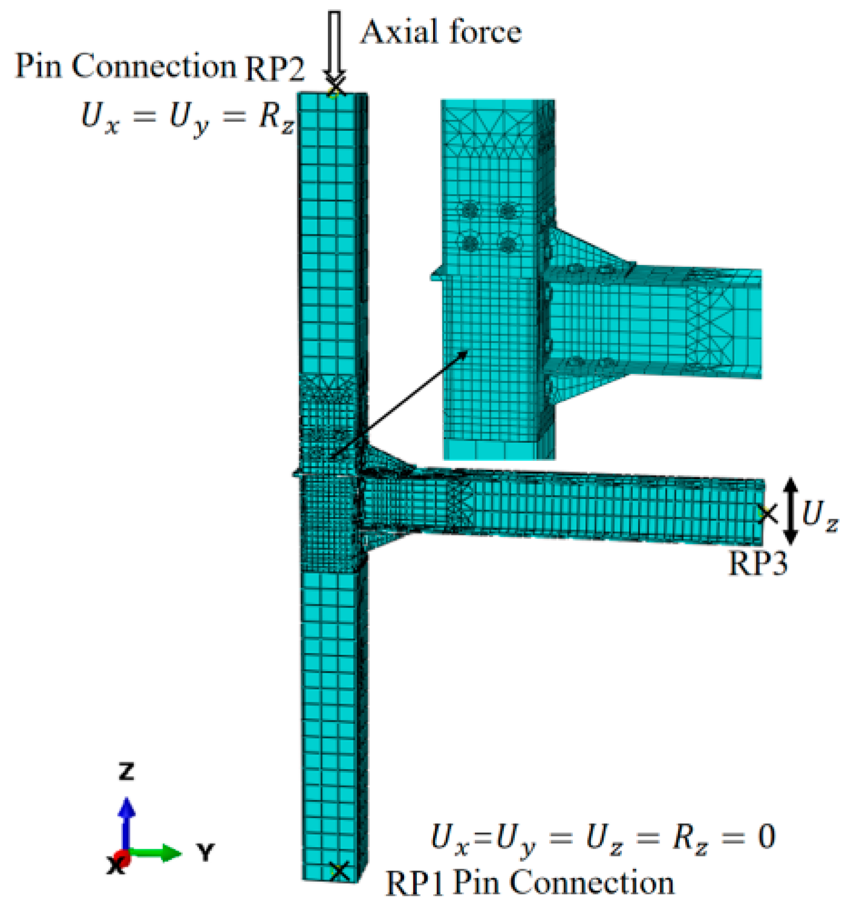
FE models were built by ABAQUS CAE. The section of the square steel tube column is 200 × 200 × 8 mm, and the section of the H-section steel beam is HM194 × 150 × 6 × 9 mm, and Q355B is used for all of the parts. The details of the finite element model are consistent with the size of the test specimens [28]. The length of the square steel tube column and H-shaped steel beam is consistent with the calculated length of the test specimens, that is, the height from the bottom of the lower module column to the top of the module column is H = 3.0 m, and the loading point of the beam to the center of the module column is L = 1.5 m. Three-dimensional solid elements are used in the model, including C3D8R and C3D6 [31]. The former was used for most regions, and the latter was used for the transition region between coarse grid and fine grid. In order to accurately simulate the stress state of the core shear zone and the surrounding area of the joint, the connection region, bolts, and bolt holes were modeled with fine meshes for better simulation of the stress-concentrated region, with a mesh element size of 15 mm (an element size of 15 mm was selected to balance computational efficiency with the accurate resolution of local stress states and plasticity development). The welding in the model adopted the constraint of a tie. Considering the contact on plate–plate and bolt–plate, the tangential friction coefficient adopted 0.25, and the normal direction was set up for hard contact. The bolt adopts the ‘dumbbell’ shape model instead of the bolt cap and bolt rod. The refined finite element model is shown in Figure 2.
The FE models include the CTH8, CTH12, and CTH16 series with a thickness of 8 mm, 12 mm, and 16 mm for the column top, respectively. The other parameters include the bolt diameter for vertical splicing, the existence of an inner diaphragm and angle steel stiffener, and the thickness of the flush endplate and angle steel. Taking the model number “CTH12w-D12-J12+” as an example, CT represents the joint, H12 represents that the thickness of the column top is 12 mm, w represents the cancellation of the inner diaphragm, D12 represents that the thickness of the flush endplate is 12 mm, and J12+ represents that the thickness of the angle steel is 12 mm and the stiffener is retained. The parameters of the FE models are shown in Table 1.

2.2. Load and Boundary Conditions

The boundary conditions of the model are imposed by the motion coupling points at the bottom of the lower module column, the top of the upper module column, and the end sections of the beam (the coupling points are set to the center point of each section). The bottom section of the lower module column constrains the three-way translational degree of freedom and the two-way rotational degree of freedom, and releases the rotational constraint in the axis direction of the pin shaft, that is, the central coupling point RP1 is set as. The top section of the upper module column constrains the two-way translational degree of freedom and the two-way rotational degree of freedom, and releases the displacement constraint in the axial direction of the column to apply axial pressure, that is, the central coupling point RP2 is set as. The beam end section constrains the out-of-plane translational degree of freedom and the two-way torsional degree of freedom, that is, the central coupling point RP3 is set as. The constrain modes of RP1, RP2, and RP3 are illustrated in Figure 2.

2.3. Validation

To verify the accuracy of the FE model, the above modeling method was used to simulate the joint specimens from reference [15]. The failure modes, moment–story drift angle hysteretic curves, and moment–story drift angle skeleton curves obtained from the test and FE analysis were compared. The failure modes from the FE analysis are compared with the test results, as shown in Figure 3, showing good agreements. The FE model could accurately simulate the local buckling of the column wall, local buckling of the beam flange, and plastic deformation of the angle steel and endplate. Figure 4 shows the hysteretic curves and skeleton curves obtained from the experiments and FE analysis for specimen CT3, which match well. Therefore, the FE analysis could provide results with satisfactory accuracy and be adopted for further analysis of the proposed joint.

3. Parametric Joint Optimization

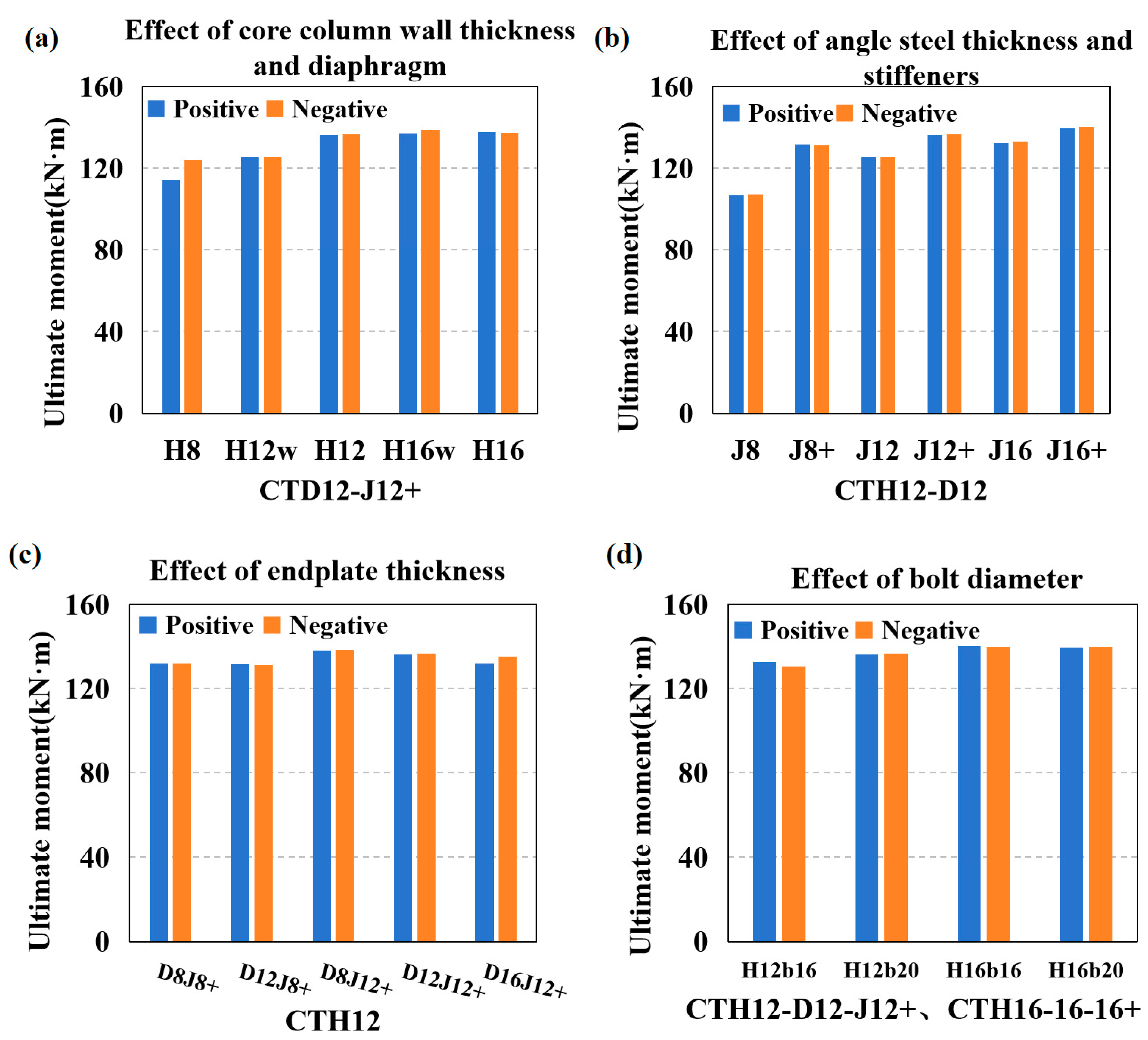
The initial rotational stiffness and ultimate moment of 20 joints are listed in Table 2. Figure 5 and Figure 6 compare, respectively, the initial rotational stiffness and ultimate bending moment of the joints under different configurations, including the core area column wall thickness, inner diaphragm, angle thickness, angle stiffeners, flat endplate thickness, and the diameter of high-strength bolts on the column flange.

3.1. Core Column Wall Thickness and Inner Diaphragm

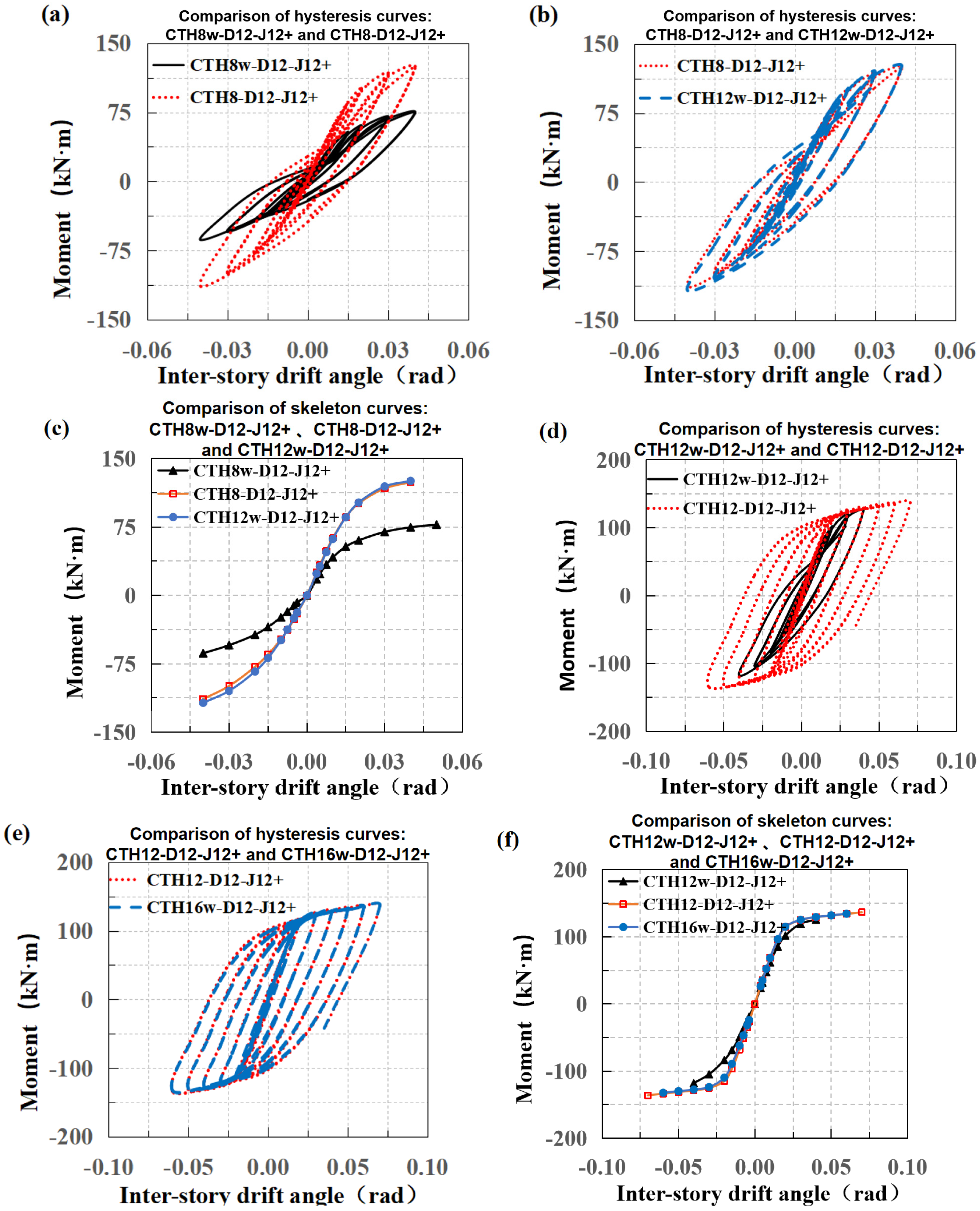
The series of specimens with an angle thickness of 12 mm (including stiffeners) and flat endplate thickness of 12 mm were selected. By varying the core area column wall thickness to 8 mm, 12 mm, and 16 mm, and considering both the presence and absence of inner diaphragms, six CT joint FE models were established as follows: CTH8w-D12-J12+, CTH8-D12-J12+, CTH12w-D12-J12+, CTH12-D12-J12+, CTH16w-D12-J12+, and CTH16-D12-J12+. Figure 7 shows the comparison of the hysteretic and skeleton curves of the CT-J12+ series joints.
Firstly, comparing specimens with core area column wall thicknesses of 8 mm and 12 mm, Figure 7a shows that the hysteretic loops of specimens with inner diaphragms are significantly fuller at each inter-story drift angle compared to those without inner diaphragms. In Figure 7c, the skeleton curves of specimens with inner diaphragms exhibit higher slopes and bending moment values at each inter-story drift angle than those without inner diaphragms. This indicates that when the core area column wall thickness is small, adding an inner diaphragm can significantly enhance the joint’s bending stiffness and load-bearing capacity.
In Figure 7b, the hysteretic curves of the thick core area column wall specimen without an inner diaphragm (CTH12w-D12-J12+) and the thin core area column wall specimen with an inner diaphragm (CTH8-D12-J12+) almost overlap. Similarly, in Figure 7c, their skeleton curves also nearly coincide. However, the positive and negative initial rotational stiffness of the former increased by 27.0% and 17.9%, respectively, compared to the latter. This suggests that thickening the column wall and adding an inner diaphragm have similar effects on improving the load-bearing performance of joints with weak core areas, but the addition of an inner diaphragm is more effective in enhancing joint stiffness.
Further comparing specimens with core area column wall thicknesses of 12 mm and 16 mm, Figure 7d shows that the hysteretic loop of the specimen with an inner diaphragm (CTH12-D12-J12+) is spindle-shaped and significantly fuller than that of the specimen without an inner diaphragm (CTH12w-D12-J12+). The positive and negative initial rotational stiffness of the former are 2.29 times and 1.52 times those of the latter, respectively. This can be explained by the fact that the inner diaphragm reduces the bulging and denting of the column flange under tensile and compressive loads, thereby enhancing the initial rotational stiffness associated with column flange deformation, as shown in Figure 7c,d.
In Figure 7e,f, the overlapping curves of the thick core area column wall specimen without an inner diaphragm (CTH16w-D12-J12+) and the thin core area column wall specimen with an inner diaphragm (CTH12-D12-J12+) further validate that thickening the column wall and adding an inner diaphragm have similar effects on improving joint performance.
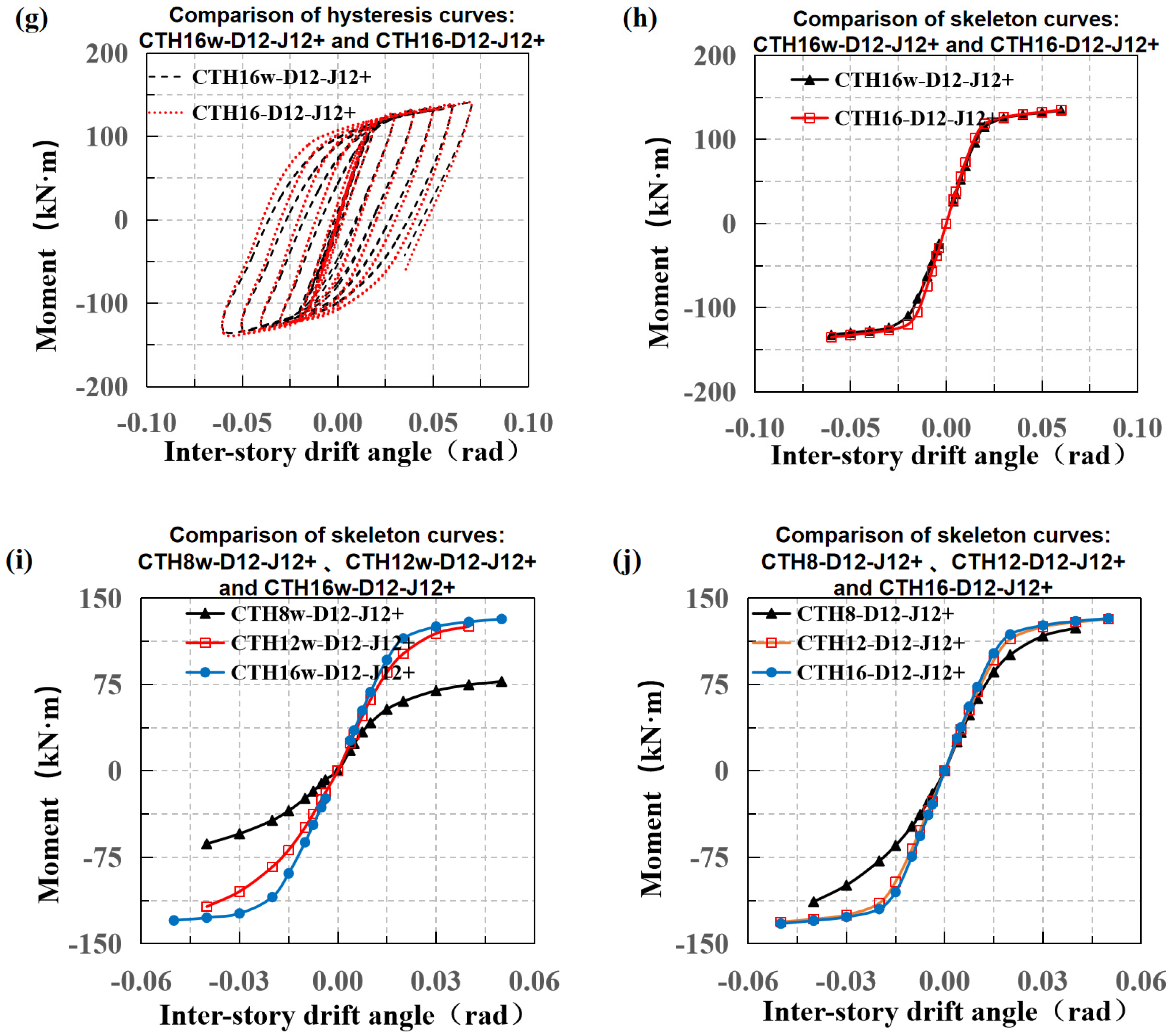
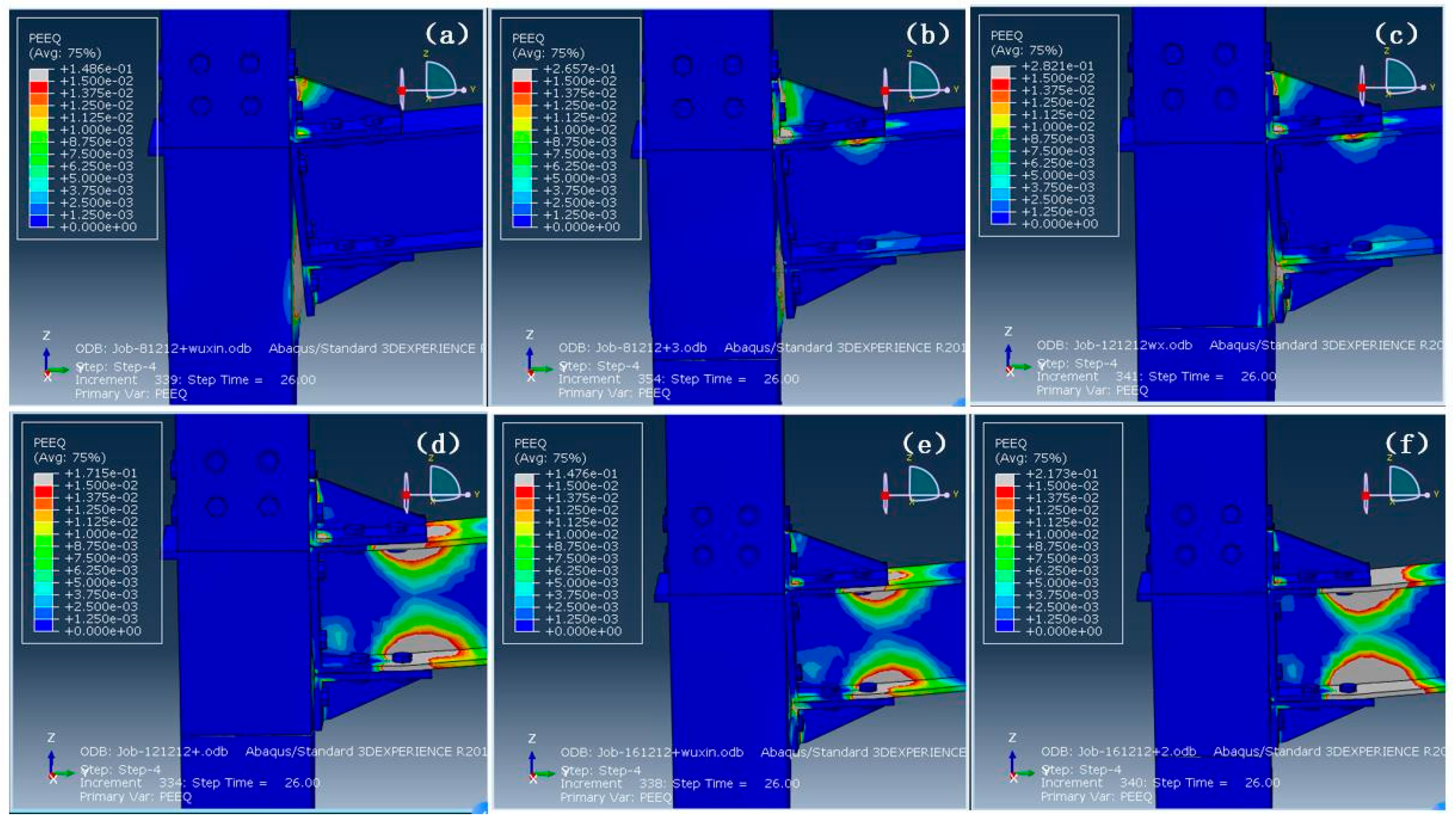
When the core area column wall thickness increases to 16 mm, the overlapping curves in Figure 7g,h indicate that the core area achieves sufficient stiffness, making the addition of an inner diaphragm only marginally effective in improving the initial stiffness of the coupled joints, with little impact on the ultimate load-bearing performance. Combining Figure 7i and Figure 8a,c,e, it can be observed that thickening the core area column wall enhances its resistance to deformation, thereby improving its bending stiffness and mitigating the bulging failure mode of the column wall. By comparing the skeleton curves of the three specimens with inner diaphragms in Figure 7j, it is evident that thickening the core area column wall when it is relatively thin significantly enhances the joint’s bending stiffness and load-bearing performance. However, once a certain thickness is reached, the presence of the inner diaphragm ensures sufficient resistance to deformation, and further thickening of the core area column wall no longer significantly improves joint performance.

3.2. Angle Thickness and Stiffener Presence

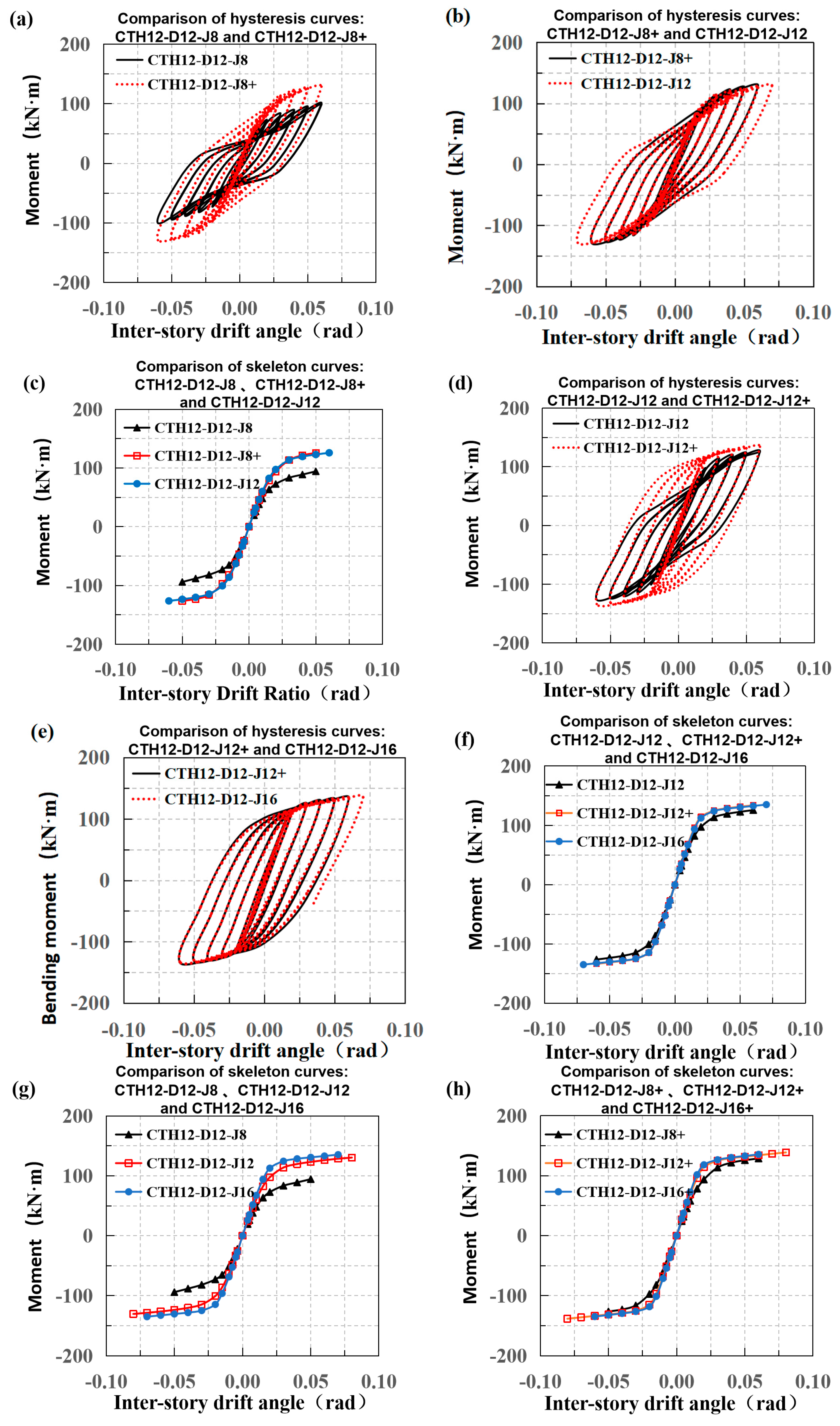
A series of specimens with a core area wall thickness of 12 mm (including inner diaphragms) and a flat endplate thickness of 12 mm were selected. By varying the angle leg thickness to 8 mm, 12 mm, and 16 mm, and considering both the presence and absence of stiffeners, six CT joint finite element models were established as follows: CTH12-D12-J8, CTH12-D12-J8+, CTH12-D12-J12, CTH12-D12-J12+, CTH12-D12-J16, and CTH12-D12-J16+. Figure 9 shows the comparison of the hysteretic curves and skeleton curves for these six specimens.
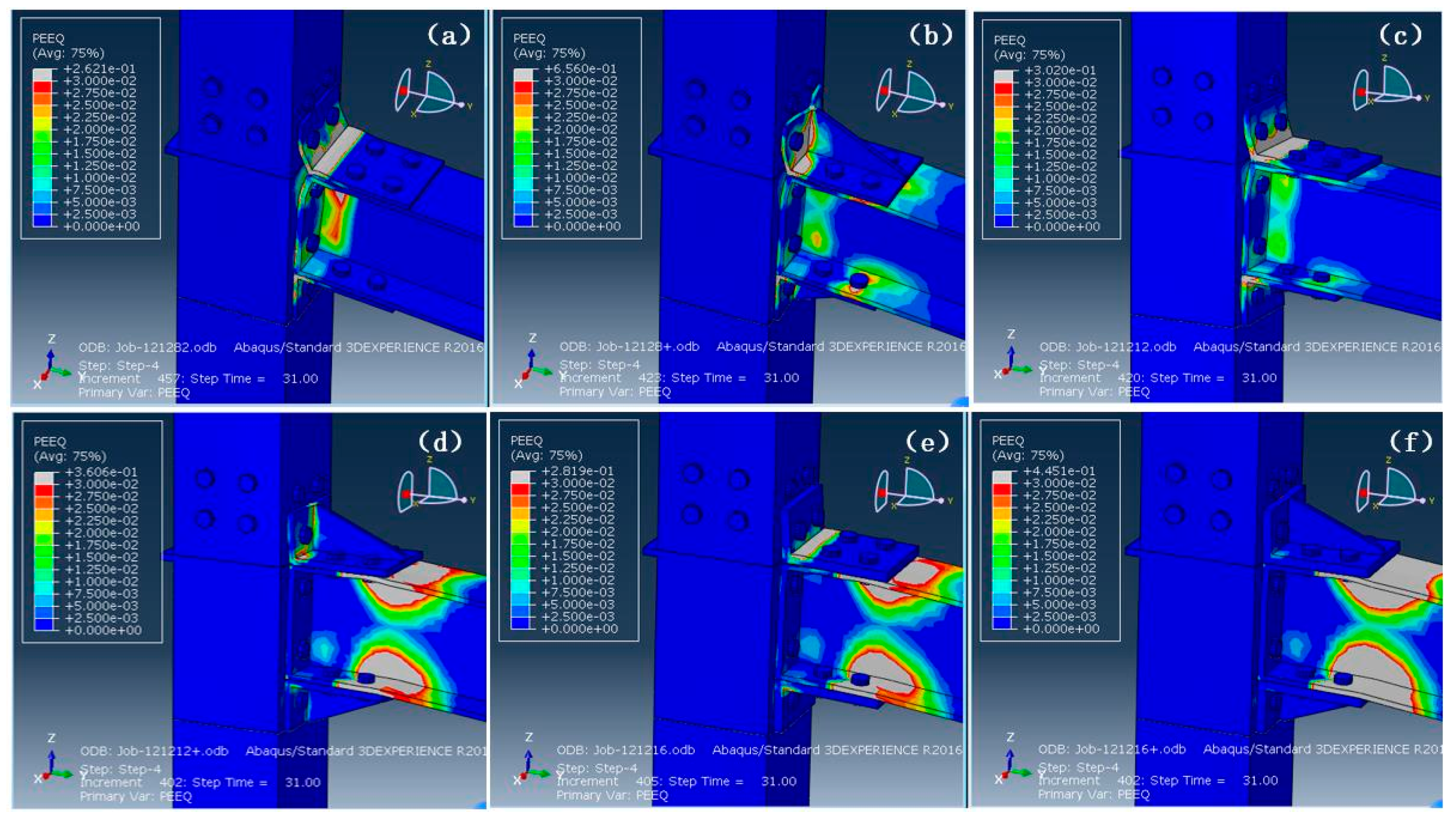
As shown in Figure 9a–c, when the thickness of the angle steel limb is relatively small, the addition of stiffeners or an increase in thickness can effectively mitigate the pinching effect of the joint hysteretic curve, transforming it from a bow shape to a spindle shape. This significantly enhances the stiffness, load-bearing capacity, and energy dissipation capability of the joint. It can be seen from Figure 6b that stiffeners are more effective than increased thickness in improving the performance of the joint. When the thickness of the angle steel limb is increased to 12 mm, the addition of stiffeners or an increase in limb thickness can further enhance the hysteretic performance of the joint, making the spindle-shaped hysteretic loop more pronounced (Figure 9d,e), while also strengthening the angle steel’s resistance to deformation and thereby improving the load-bearing capacity of the joint (Figure 10). Further comparison of the effect of stiffeners on joint performance when the angle steel limb thickness is 16 mm shows that the addition of stiffeners only slightly enhances the initial rotational stiffness and ultimate load-bearing capacity of the joint. Figure 9f indicates that the improvement in joint performance diminishes when the thickness of the angle steel is increased to a certain extent.
A longitudinal comparison of the effects of the angle steel thickness on the performance of jointed limbs with and without stiffeners reveals that increasing the thickness of the angle steel has a more pronounced effect on improving the stiffness and load-bearing capacity of the jointed limbs without stiffeners. When the limb thickness reaches a certain level, both types of joints can effectively resist deformation, and further increases in thickness no longer significantly enhance joint performance. This is particularly evident in Figure 9h, where the skeleton curves of CTH12-D12-J12+ and CTH12-D12-J16+ almost completely overlap. This can be explained by the fact that after the stiffened angle steel is enhanced to a certain degree, the deformation of the joint is mainly concentrated in the joint domain, column flange, and beam end flange, and the above parameters are kept consistent between the two.

3.3. Effect of Endplate Thickness on Joint Performance

A series of finite element models of CT joints were established with five different endplate thicknesses (8 mm, 12 mm, and 16 mm) using angle steel with a limb thickness of 8 mm and 12 mm, a core area wall thickness of 12 mm, and internal partition plates. The models included CTH12-D8-J8+, CTH12-D12-J8+, CTH12-D8-J12+, CTH12-D12-J12+, and CTH12-D16-J12+. As shown in Figure 6c, the initial rotational stiffness of the joints increased gradually with the increase in endplate thickness. For the two models with 8 mm thick angle steel limbs, the thicker endplate joint (CTH12-D12-J8+) exhibited an increase in positive and negative stiffness of 15.6% and 12.8%, respectively, compared to the thinner endplate joint (CTH12-D8-J8+). The positive and negative initial rotational stiffness of CTH12-D12-J12+ increased by 10.7% and 6.3%, respectively, compared to the corresponding parts of CTH12-D8-J12+. The positive and negative initial rotational stiffness of CTH12-D16-J12+ increased by 20.4% and 19.8%, respectively, compared to the corresponding parts of CTH12-D8-J12+. However, as shown in Figure 6c, the endplate thickness had little effect on the ultimate load-bearing capacity of the joints. This is because the endplate, being closer to the neutral axis of the jointed beam compared to the angle steel, does not exhibit significant deformation during failure and thus does not play a controlling role. The thickness of the endplate of the jointed beam should be consistent with the thickness of the angle steel. When the thickness of the angle steel is limited and an increase in joint stiffness is required, the endplate thickness can be appropriately increased.

3.4. Bolt Diameter

Based on the CTH12-D12-J12+ and CTH16-D12-J12+ components, two comparative CT joint models were established by altering the diameter of the high-strength bolts on the column wall: CTH12-b16 and CTH16-b16. As shown in Figure 5d, increasing the bolt diameter effectively enhances the initial stiffness of the joints. Specifically, in the CTH12 series, the positive and negative initial stiffness of the model with larger bolt diameters increased by 15.7% and 13.9%, respectively, compared to the model with smaller bolt diameters. Similarly, in the CTH16 series, the positive and negative initial stiffness of the model with larger bolt diameters increased by 11.3% and 10.5%, respectively, compared to the model with smaller bolt diameters. Additionally, the high pre-tension force in the high-strength bolts provides them with a strong tensile ultimate moment. In most cases, bolt fracture failure does not occur, so a small change in bolt diameter has a limited impact on the ultimate moment of the joints.

4. Mechanical Model of Fully Bolted Joints

4.1. Initial Rotational Stiffness of Joints

This section refers to the component method outlined in European Code EC3 [32] to theoretically calculate the initial rotational stiffness of the joints, which is divided into the following three steps: (1) After conducting a force analysis on the joint model, identify the effective components in the compression zone, shear zone, and tension zone of the joint region. (2) Calculate the compressive, shear, or tensile stiffness of each effective component using existing codes or methods such as T-stub analysis, and represent these components as springs with specific stiffness values. (3) Connect the springs corresponding to the tensile components of each row of bolts in series. Then, by introducing rigid bar elements to establish the spring system, further combine the spring units to derive the initial rotational stiffness of the joint.

4.2. Determination of Effective Components

This section first conducts a mechanical analysis of the joint under both positive and negative bending moments, as shown in Figure 11, to identify the rotation center and neutral axis position during the initial loading phase. Based on this analysis, mechanical models for the compression, shear, and tension zones within the joint are extracted, thereby determining the effective components subjected to compression, shear, and bending. It is assumed that during joint rotation, the neutral axis coincides with the centroid of the beam cross-section, and the rotation center is located at the center of the compressive beam flange. Additionally, the vertical shear force is transferred to the column flange via non-tension high-strength bolts.
Under the positive bending moment, the upper flange of the beam is subjected to tension, while the lower flange is under compression. Pre-tensioned high-strength bolts on the upper beam flange transfer partial tensile force to the horizontal leg of the angle steel through friction. The tensile force in the horizontal leg of the angle steel is then transferred to its vertical leg via stiffeners, while the remaining tensile force in the upper beam flange is transmitted to the flat endplate. Subsequently, high-strength bolts located above the neutral axis of the column flange transfer the tensile forces from both the vertical leg of the angle steel and the flat endplate to the column flange. These tensile forces are ultimately transferred to the column web through the upper cover plate. The compressive force at the lower beam flange is directly transferred to the column web through contact, with the lower spacer plate enhancing the compressive capacity of the column web. This results in shear forces within the column web between the lower spacer plate and upper cover plate, indicating that the column web must resist significant shear action. Specifically, the effective components of the joint (as shown in Figure 11b) include the following: a tension-resistant column flange component (cfb) at the height of two bolt rows above the neutral axis; a tension-resistant angle steel component (sta); a bolt tension component (bt); a tension-resistant flat endplate component (ept); a compression-resistant column web component (cwc) at the height of the lower beam flange; and a shear-resistant column web component (cws) between the upper and lower spacer plates. Under the negative bending moment, the lower beam flange is subjected to tension while the upper flange is under compression. The effective components are analogous to those under the positive bending moment, with one key difference: the outermost tension-resistant bolts under the negative bending moment correspond to the square tubular column flange alone, whereas under the positive bending moment, the equivalent component comprises both the square tubular column flange and an inner sleeve.

4.3. Stiffness Calculation of Effective Components

Based on existing codes and prior research, stiffness calculation formulas for different effective components are proposed according to the structural characteristics of the joint.

4.3.1. Compressive Stiffness of Column Web Component (kcwc)

Faella [33] derived the stiffness formula for the web of a stiffened H-shaped steel column at the stiffener location. For square tubular columns, both side webs contribute to the compressive resistance. Therefore, the original formula is modified by replacing the web thickness with twice the wall thickness of the square tubular column. The compressive stiffness kcwc for the stiffened square tubular column web is calculated as follows:
k c w c = 4 t c t c + t a + b c 2 t c t s p h c 2 t c
Parameters in the Formula:
  • E: Elastic modulus of the material;
  • tc: Wall thickness of the square tubular column;
  • ta: Thickness of the stiffener angle leg;
  • bc: Flange width of the square tubular column;
  • tsp: Thickness of the horizontal stiffener in the joint panel;
  • hc: Sectional height of the square tubular column.

4.3.2. Shear Stiffness of Column Web Component (kcws)

The shear-resistant column web component (cws), as part of the horizontally stiffened square tubular column web, derives its shear stiffness from an improved formula based on the shear stiffness of stiffened H-shaped steel columns [16]. Specifically, both side webs of the square tubular column are considered shear-resistant components in the joint panel. The original formula is modified by replacing the web thickness with twice the wall thickness of the square tubular column, expressed as follows:
k c w s = 2 E h b 2 t b f h c 2 t c × 2 t c 3 1 + v h b t b f 2 = 4 G h b 2 t b f h c 2 t c × 2 t c 3 h b t b f 2
Parameters in the Formula:
  • E: Elastic modulus of the steel in the joint panel;
  • G: Shear modulus of the steel in the joint panel;
  • ν: Poisson’s ratio of the steel;
  • hb: Height of the coupled beam;
  • hc: Sectional width of the square tubular column;
  • tbf: Flange thickness of the coupled beam;
  • tc: Wall thickness of the square tubular column.

4.3.3. Tensile Stiffness of Bolt Component (kbt)

Based on Faella’s method, Chen Xuesen [34] further incorporated the stiffness contribution from the increase in bolt shaft tension and proposed a simplified theoretical formula for the axial stiffness of a single high-strength bolt. In this study, Chen’s approach is extended by considering both the preload reduction between plates and the stiffness variation due to bolt shaft tension increase. The modified tensile stiffness formula is proposed as follows:
k b t = π E b t d b t ψ 0.5 + 0.25
Parameters in the Formula:
  • Ebt: Elastic modulus of the bolt material;
  • Abt: Effective cross-sectional area of the bolt shaft;
  • Lbt: Effective length of the bolt shaft;
  • tp: Thickness of the connecting plate;
  • dbt: Nominal diameter of the high-strength bolt;
  • λ: Ratio of the angle steel/flat endplate thickness to the bolt diameter.

4.3.4. Tensile Stiffness of Column Flange Component (kcfb)

Shi Gang’s research team [35] compared the deformation behavior of stiffened H-shaped steel column flanges and stiffened square tubular column flanges under tension induced by a single row of two bolts. Their analysis revealed that due to the weak constraint effect of the square tubular column web, the column flange exhibits a certain rotational capacity. To account for this, a reduction coefficient β is introduced to modify the tensile stiffness formula originally proposed for H-shaped column flanges. This coefficient specifically reduces the stiffness of the flange subpanel between the bolt axis and the column web. The final tensile stiffness formula for the square tubular column flange with internal diaphragms is expressed as follows:
k c f b 1 = β 1 c f e s c f 3 E c f b 1 c f t c f 3 + α e f c f G c f b 1 c f t c f
k c f b 2 = β 2 c f e f c f 3 E c f b 2 c f t c f 3 + α e f c f G c f b 2 c f t c f
β 1 c f = 1 e f c f 2 b 1 c f
β 2 c f = 1 e s c f 2 b 2 c f
k c f b = ξ c f k c f b 1 + k c f b 2
Parameters in the Formula:
  • kcfb1: Stiffness of the flange subpanel between the bolt axis and column web, considering both bending and shear deformation;
  • kcfb2: Stiffness of the flange subpanel between the bolt axis and internal diaphragm, considering both bending and shear deformation;
  • β1cf, β2cf: Stiffness reduction coefficients for the two flange subpanels, respectively;
  • Ecf: Elastic modulus of the column flange steel;
  • Gcf: Shear modulus of the column flange steel;
  • α: Sectional coefficient for shear deformation (α = 1.2 for rectangular sections);
  • efcf: Distance from the bolt center to the internal diaphragm;
  • escf: Distance from the bolt center to the column web;
  • b1cf, b2cf: Effective lengths of the endplate subpanels, taken as the minimum value between the actual length and (efcf + escf);
  • ξcf: Reduction coefficient accounting for the imperfect fixity constraint of the column web on the flange (ξcf = 0.7).

4.3.5. Tensile Stiffness of the Stiffened Angle Component (ksta)

By isolating the vertical leg panel of the stiffened angle, supported on both sides, and simplifying it into two opposing plate segments subjected to reverse tension (denoted as sta1 and sta2, respectively), the stiffness of these simplified plates is calculated based on the deformation stiffness formula for endplate connection with stiffened extended endplates. The tensile stiffness of the stiffened angle, ksta, is ultimately derived as follows:
k s t a 1 = β 1 a e s a 3 E a b 1 a t a 3 + α e s a G a b 1 a t a
k s t a 2 = β 2 a e f a 3 E a b 2 a t a 3 + α e f a G a b 2 a t a
β 1 a = 1 e f a 2 b 1 a
β 1 a = 1 e s a 2 b 2 a
k s t a = k s t a 1 + k s t a 2
Parameters in the Formula:
  • ksta1: Stiffness of the vertical leg panel between the bolt axis and the horizontal leg of the angle steel;
  • ksta2: Stiffness of the vertical leg panel between the bolt axis and the angle steel stiffener;
  • β1a, β2a: Stiffness reduction coefficients for the two vertical leg panels, respectively;
  • α: Section coefficient for shear deformation calculation, taken as 1.2;
  • efa, esa: Distance from bolt center to the inner surface of the horizontal leg and to the stiffener, respectively;
  • b1a, b2a: Smaller value between the actual endplate panel length and efa + esa.

4.3.6. Tensile Stiffness of the Flat Endplate Component (kept)

Based on the numerical simulation results in Chapter 3, where thin endplates exhibit both bending deformation and shear deformation, this study adopts Shi Gang’s methodology. The beam flange and web are treated as fixed supports for the flat endplate segments, and the endplate is divided into multiple support panels with different boundary conditions. Using plate–shell mechanical theory, the stiffness of each panel under bending and shear deformation is calculated. The governing formulas are as follows:
k e p 1 = β 1 e p e s e p 3 E e p b 1 e p t e p 3 + α e s e p G e p b 1 e p t e p
k e p 1 = β 2 e p e f e p 3 E e p b 2 e p t e p 3 + α e f e p G e p b 2 e p t e p
β 1 e p = 1 e f e p 2 b 1 e p
β 2 e p = 1 e f e p 2 b 2 e p
k e p = k e p 1 + k e p 2
Parameters in the Formula:
  • kep1: Stiffness of the endplate panel between the bolt axis and the beam flange, accounting for both the bending deformation and shear deformation of the flat endplate;
  • kep2: Stiffness of the endplate panel between the bolt axis and the beam web, also incorporating bending and shear deformation;
  • βep1, βep2: Stiffness reduction coefficients for the two endplate panels, respectively;
  • α: Section coefficient for shear deformation calculation, taken as 1.2;
  • efep, esep: Distance from bolt center to the beam web and beam flange, respectively;
  • b1ep, b2ep: Smaller value between the actual length of the endplate panel and efep + esep.

4.4. Stiffness Calculation Model of Modular Joints

The initial rotational stiffness of the joint is derived by integrating the deformations of the compressive, shear, and tensile components based on the fundamental stiffness formulation. The governing equation is expressed as follows:
k i n i = z e q 2 1 K c w c + 1 K c w s + 1 K e q
k e q = k e q , 1 h 1 + k e q , 2 h 2 2 k e q , 1 h 1 2 + k e q , 2 h 2 2
k e q , 1 = 1 1 2 k b t , 1 + 1 2 k c f b , 1 + 1 2 k s t a
k e q , 2 = 1 1 2 k b t , 2 + 1 2 k c f b , 2 + 1 2 k e p
z e q = k e q , 1 h 1 2 + k e q , 2 h 2 2 k e q , 1 h 1 + k e q , 2 h 2
i: Number of rows.
Based on the proposed formula for the initial rotational stiffness of joints in this section, a comparative analysis was conducted between the theoretical calculations and the experimental results of the joint specimens. As shown in Table 3, the errors between the calculated results (using the proposed component-based mechanical model for positive initial rotational stiffness) and the FE-predicted rotational stiffness values do not exceed 14% for positive loading and 19% for negative loading.

5. Conclusions

This study concludes that fully bolted joints in panelized steel modular structures predominantly behave as semi-rigid connections. Specific design strategies are established through the investigation: In cases of weak panel zones, the initial rotational stiffness and ultimate moment capacity are effectively enhanced by either adding inner diaphragms or increasing the column wall thickness, with the diaphragm method providing superior improvement. To mitigate column wall buckling, it is recommended that the panel zone column wall thickness be designed to match the angle steel thickness. For joints where the angle steel is the critical component, both the addition of stiffeners and an increase in leg thickness lead to significant gains in stiffness and capacity, with stiffeners yielding the more pronounced effect. The implementation of stiffened angle steel is advised, with its leg thickness exceeding that of the coupled beam flange by 2–4 mm. The bolt diameter used in the endplate-to-column flange connection is identified as a key parameter affecting the initial rotational stiffness, though its impact on the ultimate moment capacity is minimal. Optimal design suggests that the flat endplate thickness should be equal to the angle steel thickness, and the bolt diameter should be proportional to the connector thickness.
Following the EC3 component-based method, the governing components for the joint’s initial rotational stiffness were identified, and their respective stiffness calculation formulas were derived. A comprehensive mechanical model and an analytical formula for the initial rotational stiffness were subsequently established. Validation against the finite element results indicates a high level of accuracy, with errors not exceeding 14% under the positive moment and 19% under the negative moment, confirming the formula’s applicability for the theoretical analysis of panelized modular steel joints.

Author Contributions

H.W.: conceptualization, supervision; X.L.: methodology, writing—review and editing; C.T.: investigation, methodology, writing—original draft; J.C.: writing—original draft; X.W.: investigation, methodology. C.Z.: writing—original draft preparation; Y.L.: supervision, methodology. All authors have read and agreed to the published version of the manuscript.

Funding

This research was funded by the National Natural Science Foundation of China, grant number 52208160 and Tianjin Science and Technology Program of China, grant number 23YDTPJC00190.

Data Availability Statement

The original contributions presented in this study are included in the article. Further inquiries can be directed to the corresponding author.

Acknowledgments

The authors would like to acknowledge the financial support from the National Natural Science Foundation of China (Grant No. 52208160) and the Tianjin Science and Technology Program of China (23YDTPJC00190).

Conflicts of Interest

Authors Chuan Zhao and Yanlai Li were employed by the company China MCC22 Group Co., Ltd. The remaining authors declare that the research was conducted in the absence of any commercial or financial relationships that could be construed as a potential conflict of interest.

References

  1. Jaillon, L.; Poon, C. Life cycle design and prefabrication in buildings: A review and case studies in Hong Kong. Autom. Constr. 2014, 39, 195–202. [Google Scholar] [CrossRef]
  2. Lacey, A.; Chen, W.; Hao, H.; Bi, K. Review of bolted inter-module connections in modular steel buildings. J. Build. Eng. 2019, 23, 207–219. [Google Scholar] [CrossRef]
  3. Choi, H.; Choi, Y.; Choi, C. Development and testing of precast concrete beam-to-column connections. Eng. Struct. 2013, 56, 1820–1835. [Google Scholar] [CrossRef]
  4. Thai, H.; Ngo, T.; Uy, B. A review on modular construction for high-rise buildings. Structures 2020, 28, 1265–1290. [Google Scholar] [CrossRef]
  5. Fan, J.; Yang, L.; Wang, Y.; Ban, H. Research on seismic behaviour of square steel tubular columns with deconstructable splice joints. J. Constr. Steel Res. 2022, 191, 107204. [Google Scholar] [CrossRef]
  6. Li, D.; Uy, B.; Aslani, F.; Patel, V. Behaviour and design of demountable CFST column-column connections under tension. J. Constr. Steel Res. 2017, 138, 761–773. [Google Scholar] [CrossRef]
  7. Ferdous, W.; Bai, Y.; Ngo, T.; Manalo, A.; Mendis, P. New advancements, challenges and opportunities of multi-storey modular buildings-a state-of-the-art review. Eng. Struct. 2019, 183, 883–893. [Google Scholar] [CrossRef]
  8. Luo, F.; Bai, Y.; Hou, J.; Huang, Y. Progressive collapse analysis and structural robustness of steel-framed modular buildings. Eng. Fail. Anal. 2019, 104, 643–656. [Google Scholar] [CrossRef]
  9. Xu, B.; Xia, J.; Chang, H.; Ma, R.; Zhang, L. Flexural behaviour of pairs of laminated unequal channel beams with different interfacial connections in cornersupported modular steel buildings. Thin Walled Struct. 2020, 154, 106792. [Google Scholar] [CrossRef]
  10. Liu, X.; Yang, Z.; Wang, H.; Zhang, A.; Pu, S.; Chai, S.; Wu, L. Seismic performance of H-section beam to HSS column connection in prefabricated structures. J. Constr. Steel Res. 2017, 138, 1–16. [Google Scholar] [CrossRef]
  11. Liu, X.; Cui, F.; Zhan, X.; Yu, C.; Jiang, Z. Seismic performance of bolted connection of H-beam to HSS-column with web end-plate. J. Constr. Steel Res. 2019, 156, 167–181. [Google Scholar] [CrossRef]
  12. Liu, X.; Liu, Y.; Chen, X.; Zhang, A. Analysis of bolted connection for H-section beam and square steel tube column. Structures 2024, 60, 105945. [Google Scholar] [CrossRef]
  13. Zhang, A.; Li, C.; Liu, X.; Chen, X. Seismic performance of joint for H-beam to CFST column with field-bolted flange-splicing. J. Constr. Steel Res. 2022, 196, 107375. [Google Scholar]
  14. Wu, C.; Liu, J.; Tan, W.; Wang, P. Seismic behavior of composite interior joints of prefabricated H-shaped steel reinforced concrete column—Steel beam. Structures 2020, 23, 558–572. [Google Scholar] [CrossRef]
  15. Wu, C.; Yu, S.; Liu, J.; Chen, G. Development and testing of hybrid precast steel-reinforced concrete column-to-H shape steel beam connections under cyclic loading. Eng. Struct. 2020, 211, 110460. [Google Scholar]
  16. Wu, C.; Liu, J.; Wang, Q.; Mou, B.; Pan, W. Mechanical properties of modular prefabricated steel-concrete composite internal joints under cyclic loading. J. Constr. Steel Res. 2021, 178, 106463. [Google Scholar] [CrossRef]
  17. Wu, C.; Fan, M.; Song, H.; Mou, B.; Wang, X.; Yu, S.; Liu, C.; Men, J. Elastic-plastic analysis of a novel prefabricated SRC column-steel beam composite frame structure. Structures 2024, 68, 107208. [Google Scholar] [CrossRef]
  18. Chu, Y.; Zhong, Y.; Luo, P.; Chen, X.; Xia, H. Experimental study on the seismic performance of the new fully-bolted beam-column joint. J. Constr. Steel Res. 2022, 199, 107619. [Google Scholar] [CrossRef]
  19. Chu, Y.; Chen, X.; Zhong, Y.; Xia, H. Seismic fragility analysis of the steel frame with new layered assembled joints. Structures 2023, 58, 105380. [Google Scholar] [CrossRef]
  20. Chu, Y.; Chen, X.; Zhong, Y.; Xia, H. Seismic fragility analysis of steel frames with fully-bolted core tube joints. Structures 2024, 20, 208–221. [Google Scholar]
  21. Zhang, Z.; Wang, H.; Qian, H.; Gao, K.; An, B.; Fan, F. Design and mechanical performance analysis of a new type of column-column-beam prefabricated steel frame joint. Struct. Eng. Int. 2021, 31, 418–426. [Google Scholar] [CrossRef]
  22. Zhang, Z.W.; Li, D.; Wang, H.J.; Qian, H.L.; Fang, W.Q.; Jing, X.F.; Fan, F. Study of mechanical properties of a novel column-beam-column prefabricated steel frame joint. Adv. Steel Constr. 2024, 20, 330–344. [Google Scholar]
  23. Li, Y.; Wu, F.; Tan, M. Static performance of non-through one-side bolted end-plate joint for floor-by-floor assembled steel structures. Structures 2023, 48, 288–303. [Google Scholar] [CrossRef]
  24. Wang, X.; Wang, Y.; An, Q. Moment resistance and stiffness of an assembled beam-column joint with high-strength bolt and external diaphragm. J. Tianjin Univ. Sci. Technol. 2019, 52, 75–82. [Google Scholar]
  25. Wang, X.; Wang, Y. Bending capacity of prefabricated beam-column joints with external diaphragm high-strength bolted connections. Ind. Build. 2020, 50, 58–65. [Google Scholar]
  26. Wang, X.; Wang, Y.; An, Q. Experimental study on seismic behavior of prefabricated beam-to-column high-strength bolted joint with external diaphragms. China Civil. Eng. J. 2020, 53, 53–64. [Google Scholar]
  27. Lu, Y.; Lei, P.; Ban, H. Experimental study on demountable and reusable steel beam-to-column joints with bolted-pinned connections. J. Constr. Steel Res. 2024, 214, 108450. [Google Scholar]
  28. Montuori, R.; Nastri, E.; Piluso, V.; Troisi, M. Influence of connection typology on seismic response of MRFrames with and without ‘set-backs’. Earthq. Eng. Struct. Dyn. 2017, 46, 5–25. [Google Scholar] [CrossRef]
  29. Chen, M.; Geng, Y.; Li, B.; Lu, W.; Hu, F.; Zhang, X.; Guo, Y. Research on lateral load-resisting performance of cruciform cold-formed steel built-up columns. J. Constr. Steel Res. 2025, 229, 109529. [Google Scholar] [CrossRef]
  30. Wang, H.; Zhao, X.; Ma, G. Experimental study on seismic performance of column-column-beam joint in panelised steel-modular structure. J. Constr. Steel Res. 2022, 192, 107240. [Google Scholar] [CrossRef]
  31. Bagheri, M.; Malidarreh, N.R.; Ghaseminejad, V.; Asgari, A. Seismic resilience assessment of RC superstructures on long-short combined piled raft foundations: 3D SSI modeling with pounding effects. Structures 2025, 81, 110176. [Google Scholar] [CrossRef]
  32. EN1993-1-8: 2005; Eurocode 3-Design of Steel Structures-Part 1-8: Design of Joints. European Committee for Standardization: Brussels, Belgium, 2005.
  33. Faella, C.; Piluso, V.; Rizzano, G. Structural Steel Semirigid Connections: Theory, Design, and Software; CRC Press: Boca Raton, FL, USA, 1999. [Google Scholar]
  34. Chen, X.; Shi, G.; Zhao, J.; Yu, H.; Wei, D. Calculation method of moment-rotation curves for ultra-large capacity end-plate joints based on component method. Eng. Mech. 2017, 34, 30–41. [Google Scholar]
  35. Shi, G.; Chen, X. Moment-rotation curves of ultra-large capacity end-plate joints based on component method. J. Constr. Steel Res. 2017, 128, 451–461. [Google Scholar] [CrossRef]
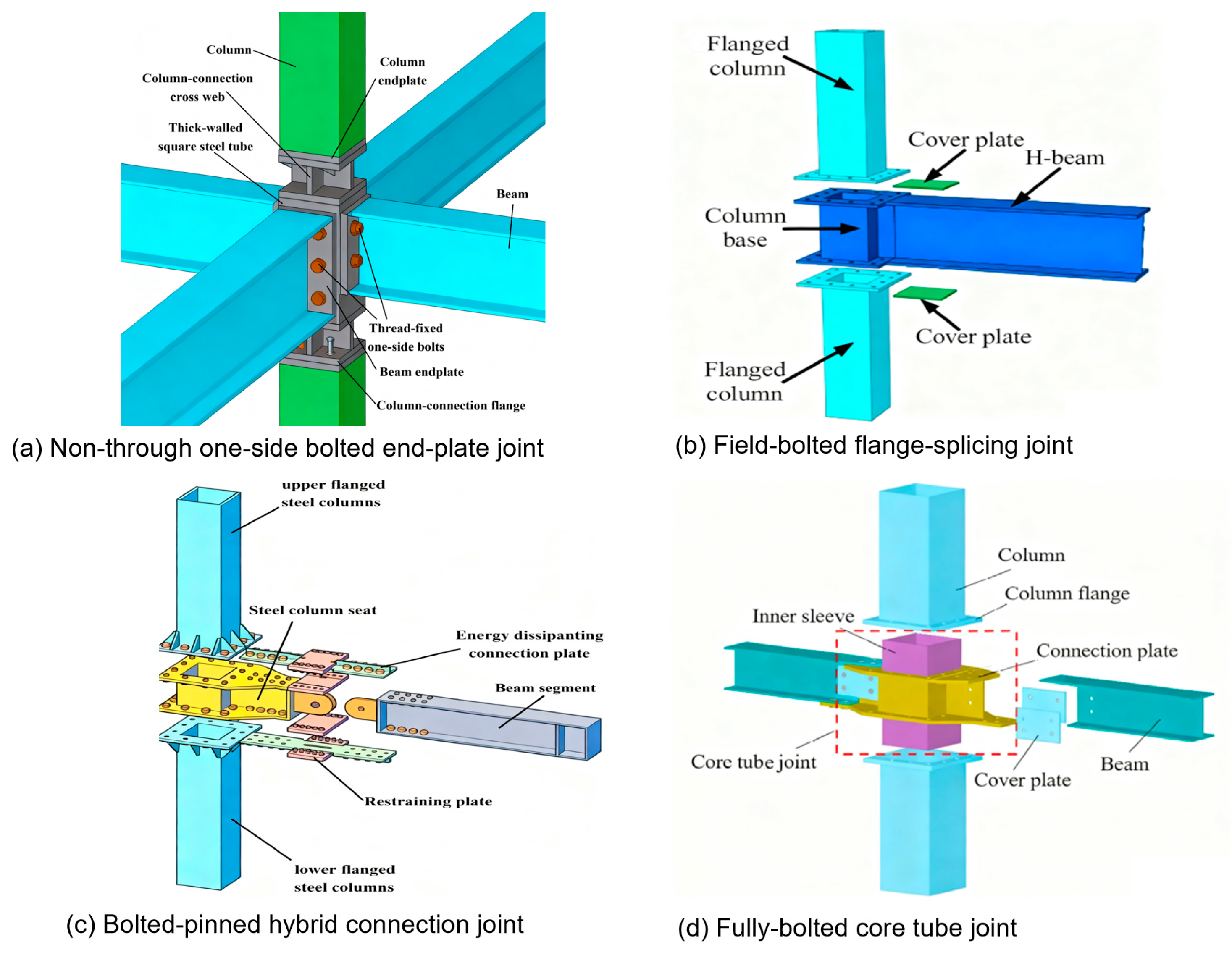
Figure 1. Column–column–beam joints by previous researchers.
Buildings 15 03807 g001
Figure 2. FE model of the panelized modular joint.
Buildings 15 03807 g002
Figure 3. Failure mode of model tests and numerical simulations.
Buildings 15 03807 g003
Figure 4. Comparison of CT3 (a) M-θ hysteretic curve; (b) M-θ skeleton curve.
Buildings 15 03807 g004
Figure 5. Comparison of initial rotational stiffness.
Buildings 15 03807 g005
Figure 6. Comparison of ultimate moment.
Buildings 15 03807 g006
Figure 7. Comparison of hysteretic and skeleton curves of CT-J12+ series joints.
Buildings 15 03807 g007aBuildings 15 03807 g007b
Figure 8. Plastic strain diagram of panelized steel modular structure joints at −0.03 rad. (a) CTH8w-D12-J12+; (b) CTH8-D12-J12+; (c) CTH12w-D12-J12+; (d) CTH12-D12-J12+; (e) CTH16w-D12-J12+; (f) CTH16-D12-J12+.
Buildings 15 03807 g008
Figure 9. Hysteretic and skeleton curves of the CTH12 series joints.
Buildings 15 03807 g009
Figure 10. Plastic strain diagram of panelized steel modular structure joints at 0.04 rad. (a) CTH12-D12-J8; (b) CTH12-D12-J8+; (c) CTH12-D12-J12; (d) CTH12-D12-J12+; (e) CTH12-D12-J16; (f) CTH12-D12-J16+.
Buildings 15 03807 g010
Figure 11. Plated modular steel structure joint. (a) Force transfer mechanism under positive bending moment; (b) effective components under positive bending moment; (c) force transfer mechanism under negative bending moment; (d) effective components under negative bending moment.
Buildings 15 03807 g011
Table 1. Number and dimensions of specimens.
Model NumberThickness/mmCancellationBolt Diameters/mm
Column TopFlush EndplateAngle SteelInner DiaphragmRib Stiffener
CTH8-D8-J8+888NoNo20
CTH8-D8-J12+8812NoNo20
CTH8-D12-J8+8128NoNo20
CTH8-D12-J12+81212NoNo20
CTH12-D8-J8+1288NoNo20
CTH12-D8-J12+12812NoNo20
CTH12-D12-J812128NoYes20
CTH12-D12-J8+12128NoNo20
CTH12-D12-J12+121212NoNo20
CTH12-D12-J12121212NoYes20
CTH12w-D12-J12+121212YesNo20
CTH12-D12-J16+121216NoNo20
CTH12-D12-J16121216NoYes20
CTH12-D16-J12+121612NoNo20
CTH12-D16-J16+121616NoNo20
CTH16-D12-J12+161212NoNo20
CTH16w-D12-J12+161212YesNo20
CTH16-D16-J16+161616NoNo20
CTH12-b16121212NoNo16
CTH16-b16161212NoNo16
Table 2. Initial rotational stiffness and ultimate moment of 20 joints.
Model NumberInitial Rotational Stiffness
/kN·m/rad
Ultimate Moment
/kN·m
PositiveNegativePositiveNegative
CTH8-D8-J8+848211,625105.37110.77
CTH8-D8-J12+997915,664105.39110.80
CTH8-D12-J8+935512,311108.26112.64
CTH8-D12-J12+10,90416,547114.49124.21
CTH12-D8-J8+14,12615,073132.00131.85
CTH12-D8-J12+17,76720,014138.00138.46
CTH12-D12-J811,10112,855106.85106.96
CTH12-D12-J8+16,32917,007131.55131.42
CTH12-D12-J12+19,66621,265136.45136.81
CTH12-D12-J1216,52917,856125.67125.47
CTH12w-D12-J12+858414,030112.08124.02
CTH12-D12-J16+21,38423,772139.43140.18
CTH12-D12-J1619,41221,210132.30133.07
CTH12-D16-J12+21,38423,968131.87135.20
CTH12-D16-J16+22,78624,230137.36137.78
CTH16-D12-J12+25,75924,623137.68137.32
CTH16w-D12-J12+16,14827,299136.97138.97
CTH16-D16-J16+30,22829,023139.49139.90
MT16w-RBS16,99518,667132.81130.56
MT16w-RWS27,15626,255140.38139.93
Table 3. Comparison of theoretical and FE values for initial rotational stiffness of specimens.
SpecimenLoading DirectionTheoretical Value
(kN·m/rad)
Finite Element Value
(kN·m/rad)
Finite Element Value/Theoretical Value
CTH8-D8-J8+Positive922384820.92
Negative14,41111,6250.81
CTH8-D12-J12+Positive11,32810,9040.96
Negative20,42816,5470.81
CTH12-D8-J8+Positive15,01914,1260.94
Negative16,67015,0730.90
CTH12-D12-J12+Positive21,38619,6660.92
Negative24,44121,2650.87
CTH12-D12-J16+Positive25,08522,7860.91
Negative27,72924,2300.87
CTH16-D12-J12+Positive29,84825,7590.86
Negative27,78324,6230.89
CTH16-D16-J16+Positive31,89830,2280.95
Negative32,23629,0230.90
Disclaimer/Publisher’s Note: The statements, opinions and data contained in all publications are solely those of the individual author(s) and contributor(s) and not of MDPI and/or the editor(s). MDPI and/or the editor(s) disclaim responsibility for any injury to people or property resulting from any ideas, methods, instructions or products referred to in the content.