Article

Vertical Deformation Calculation Method and In Situ Protection Design for Large-Span Suspended Box Culverts

1
College of Transportation Engineering, Nanjing Tech University, Nanjing 211816, China
2
College of Civil Engineering, Fuzhou University, Fuzhou 350116, China
*
Authors to whom correspondence should be addressed.
Buildings 2025, 15(20), 3804; https://doi.org/10.3390/buildings15203804
Submission received: 18 September 2025 / Revised: 18 October 2025 / Accepted: 19 October 2025 / Published: 21 October 2025

Abstract

Underground power pipelines are often encased in box culverts and buried in soil. When foundation pit excavation involves such existing pipelines, the buried box culverts can become partially suspended, risking excessive vertical deformation and requiring effective in situ protection. This study proposed analytical methods to calculate the vertical deformation of large-span box culverts under both unprotected and protected conditions. A case study of the 112 m suspended power box culverts at Yunnan Road Station on Nanjing Metro Line 5 is presented, where the methods are applied to determine the maximum allowable unsupported span and to formulate specific support and suspension protection schemes, which include a number of protection points and their spacing. Validation through ABAQUS modeling shows strong agreement among theoretical predictions, numerical simulations, and field measurements. Parametric analysis further demonstrated that the height, width, and modulus of the reinforced soil around the buried section all have a significant influence on the deformation control effectiveness. This study provides a combined theoretical framework and practical design guidelines for deformation control of large-span suspended box culverts in engineering applications.

1. Introduction

Municipal pipelines serve as critical lifelines for urban infrastructure, facilitating the transportation of essential resources and sustaining the regular operation of cities. However, the construction of underground engineering projects poses significant safety risks to adjacent buried pipelines, making this issue a primary concern in urban underground construction [1,2].
Analytical and numerical simulation methods are widely employed to investigate the effects of tunnel excavation on adjacent pipelines owing to their computational efficiency and intuitive visualization [3,4]. Previous research has developed various approaches to predict pipeline responses under different conditions [5]. Zhang et al. [6] developed an analytical solution for predicting lateral responses of existing piles induced by adjacent shield tunneling. Their approach integrated an improved Loganathan formula to estimate horizontal soil displacement and incorporated pile-soil interaction effects through finite difference modeling. Fu et al. [7] adopted a Pasternak foundation beam model to represent pipeline-soil interaction, establishing separate differential equations for the voided and coordinated deformation zones. Their model provided solutions for pipeline deflection, internal forces, and the extent of soil-pipeline separation. To address the behavior of pipelines with discontinuous interfaces, Zhang et al. [8] proposed a simplified theoretical analysis of the response of a stiff discontinuous interface pipeline under tunnel excavation conditions based on a modified Winkler foundation model with virtual nodes to consider the mechanical properties at the pipeline interface. Zhang et al. [9] introduced a closed-form solution for estimating pipeline deformation due to quasi-rectangular shield tunneling, combining convergence deformation models with Winkler foundation theory.
Further studies have contributed to understanding pipeline deformation mechanisms [10,11,12,13]. Wang et al. [14] considered the pipeline and the surrounding soil as a whole and proposed an analytical solution for the deformation of the adjacent pipeline caused by the excavation of the foundation pit based on the Pasternak elastic foundation beam model. Wang et al. [15] proposed the deflection and internal force equations for buried steel pipes in local overhang based on the Winkler elastic foundation beam model for the case of soil loss below buried pipelines. Liang et al. [16] adopted Pasternak foundation beam theory to establish governing equations for the displacement and internal force of pipelines following suspension. Complementing these analytical approaches, Li et al. [17] used ABAQUS to study the effects of erosion cavities, soil type, and other factors on pipeline deformation for the overhang caused by soil erosion below the pipeline. Liu et al. [18] introduced an analytical solution predicting spatiotemporal deformation of pipelines parallel to advancing shield tunnels, incorporating multiple excavation-induced forces and proposing characteristic curves to inform deformation control and grouting strategies. Additionally, Zhao et al. [19] developed a mechanical model based on the Euler–Bernoulli beam theory to analyze the deformation of pipelines obliquely crossed by shield tunnels, emphasizing the critical role of pipeline stiffness in deformation control.
It is important to note that existing research primarily focuses on the stress and deformation of pipelines with both ends embedded in soil and a central suspended section. However, during construction, pipelines with large unsupported spans often require protective measures to control deformation. Although various methods for pipeline protection are available, as summarized in Table 1, studies on the deformation of suspended pipeline sections following the implementation of such protective measures remain limited.
For removable pipelines, relocation is occasionally adopted as a protective measure. However, due to its substantial cost, in situ protection methods are more frequently employed. These in situ protection measures generally fall into two main categories: suspension protection and support protection. The suspension protection method involves placing longitudinal beams above the pipeline, with steel ropes or steel sections connecting the beams to the pipeline, forming a protective system [25,26]. When protecting pipelines from deformation due to their self-weight, the suspension system requires high-strength steel ropes or profiles. Consequently, its applicability is limited to municipal pipelines that are sensitive to large spans and displacements. On the other hand, the support method involves constructing lattice columns and longitudinal beams beneath the suspended pipeline, forming a rigid bridge. This system is more stable than the suspension system, with minimal overall deformation under the self-weight of the pipeline and effective vertical displacement control. However, the support method incurs high construction costs due to the need for lattice columns and beams and occupies substantial construction space. Therefore, accurately determining the spacing between support points is crucial, as it not only impacts costs and frees up construction space but also ensures the reliability and economic efficiency of the protection solution [27].
There have been similar cases and studies regarding suspended municipal pipeline in situ protection [28]. Buckland Talyor [23] designed a large support protection device for a gas transmission line that spanned 350 m of a liquefied natural gas plant in Guinea, to carry the pipeline through unstable geotechnical slopes. Ferdinand Tschemmernegg et al. [29] designed a suspension protection structure for a section of sewer pipe with an overhanging length of 137 m. Liu et al. [24] proposed and validated an in situ suspension protection technology through integrated numerical simulation (ABAQUS) and field monitoring, addressing the challenge of protecting utility tunnels adjacent to new excavations. Guo et al. [30] developed a sophisticated analytical model based on the elastic foundation beam theory and equivalent spring boundaries to simulate pipeline-soil interaction, highlighting the importance of capturing boundary effects for mechanical performance. For the West Yuanhetang tunnel in Suzhou, Jiangsu province, China, a new suspension protection technique was proposed that utilized the existing excavation support system to carry shallow-buried large-diameter pipelines, eliminating the need for dedicated structures and demonstrating effective performance through 3D FEM analysis [31]. Zhang proposed a support-like protective device for pipelines crossing adverse geological conditions, addressing issues of overlying soil dent and collapse. Based on finite element analysis software, this device can be effectively applied to crossing pipelines at different locations [32].
In summary, existing practices for protecting pipelines reveal a reliance on established specifications and case-specific empirical solutions [33,34,35,36]. For instance, common rules [37] often prescribe conservative, fixed support spacings regardless of specific culvert dimensions and soil properties. Furthermore, while case studies such as the suspension protection of a 180 m high-voltage cable [38] and the innovative use of excavation support systems for pipeline suspension demonstrates practical applications [30,31], their analytical approaches frequently lack a comprehensive consideration of the coordinated deformation between the suspended span and the settling soil at the buried ends [39]. This oversight can lead to either unsafe designs or overly conservative and costly solutions. Consequently, a comprehensive analytical method that incorporates all key factors—including coordinated deformation across span, side-span, and buried sections, as well as soil settlement effects—to calculate the full-span deformation of pipelines under both unprotected and protected conditions is still not available.
To bridge this gap, this study investigates the in situ protection of power pipelines housed within a large-diameter box culvert at Yunnan Road Station of Nanjing Metro Line 5. By dividing the box culverts into mid-span, side-span, and buried sections, and comprehensively considering the coordinated deformation of each section along with soil settlement while incorporating structural cross-sectional characteristics, this study established analytical methods for vertical deformation under both unprotected and protected conditions. Then the maximum allowable protection spacing was derived. Furthermore, specific design schemes for both support and suspension protection are proposed based on derived deformation calculation formulas. In addition, three-dimensional finite element models are constructed in ABAQUS to validate the analytical solutions, while parametric sensitivity analyses are conducted to assess the influence of reinforcement depth, width, and modulus of the soil surrounding the buried section. By explicitly incorporating soil settlement effects at both ends of the box culverts, this study provides a comprehensive assessment of culvert stability under protection, combining theoretical and numerical perspectives. Given the complexity of the construction site and the limitations of field monitoring—where available data are sparse and subject to disturbances—the measured results are used primarily as reference benchmarks to validate both the analytical models and the numerical simulations, thereby confirming the engineering applicability of the proposed method.

2. Engineering Background

Yunnan Road Station is located at the intersection of Beijing West Road and Yunnan Road in Gulou District, Nanjing, Jiangsu province, China, serving as a transfer hub between Metro Lines 4 and 5. The proposed Line 5 Yunnan Road Station, aligned along Yunnan Road, features a three-level underground island platform with a 213.9 m long main structure and burial depths ranging from 23.3 to 24.4 m, connecting directly with the operational Line 4 (as shown in Figure 1). The surrounding area contains dense underground pipeline networks. As shown in Figure 2, within the underground excavation section of the foundation pit, there exists a 6-circuit 110 kV pipeline that intersects with the foundation pit for a length of 112 m, with an average burial depth of 1.5 m. The pipeline is encased in cast-in-place reinforced concrete box culverts designed to enclose and provide protection.
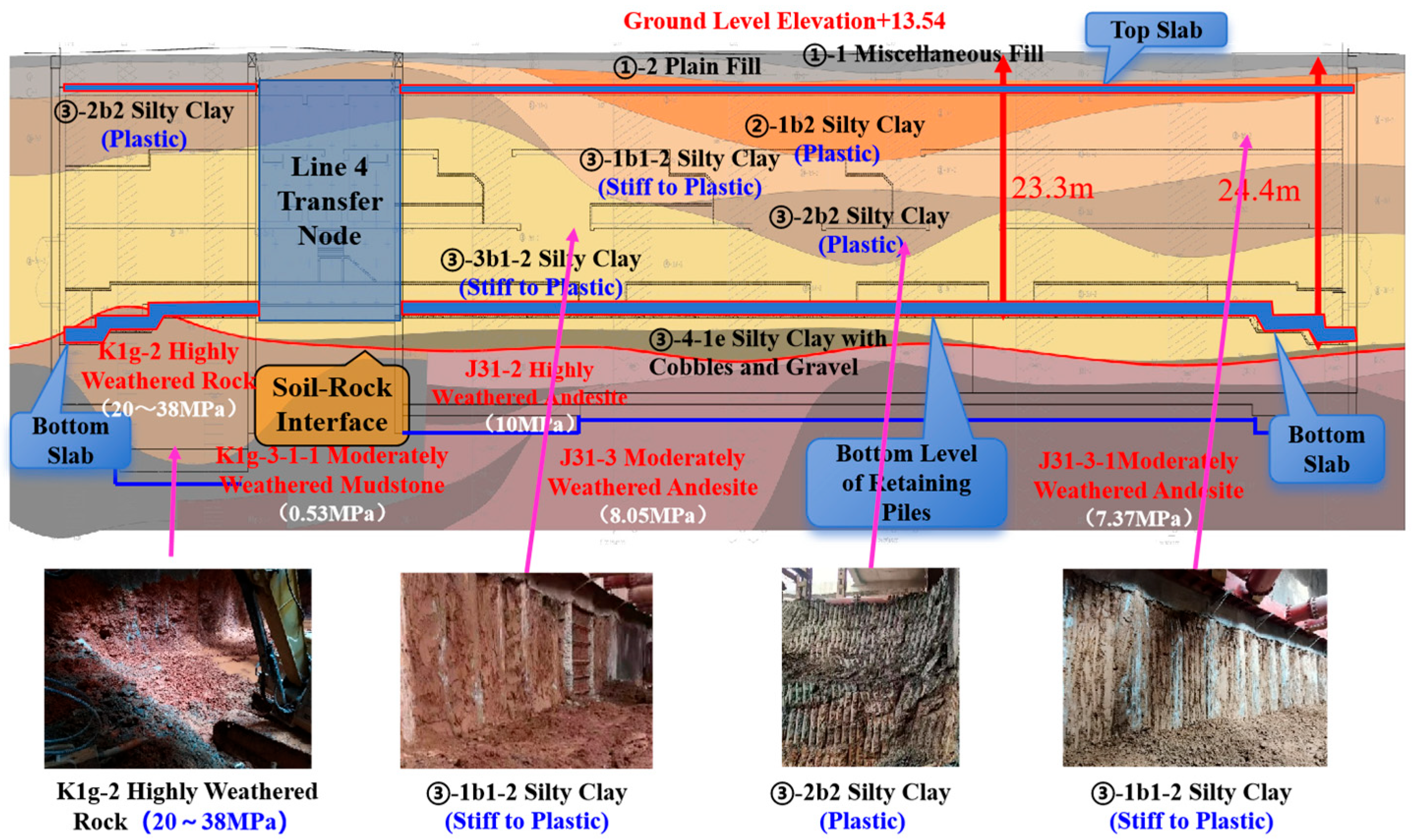
As shown in Figure 3, the site comprises weakly permeable stiff-plastic powdery clay in the upper stratum, underlain by strongly weathered rock formations with a fissure zone located 2.5 m below ground level. As soil excavation proceeds, the crossing pipeline gradually becomes partially exposed and suspended. At this stage, owing to the extreme length of the suspended section, protective measures must be implemented to restrict the deformation of the suspended section.
Given the above engineering context and geotechnical constraints, it is essential to quantitatively assess the mechanical behavior of the box culverts under both unprotected and protected conditions. The following sections will systematically present the methodologies developed to calculate culvert deformation and the corresponding protective schemes. First, the vertical deformation of the box culverts without any protective measures will be analyzed. Subsequently, deformation behavior under support and suspension protection will be computed and compared. Finally, a comparative analysis of the two protection measures will be provided to inform optimal decision-making in similar underground engineering scenarios.

3. Materials and Methods

3.1. Vertical Deformation of the Box Culverts Without Protection

3.1.1. Vertical Deformation Calculation Formula

Under unsupported conditions, progressive soil excavation beneath the utility tunnel results in gradually increasing unsupported spans, which amplify vertical deformation that may compromise pipeline operation. This section establishes a full-span mechanical model of the underground utility tunnel to calculate vertical deformation without support protection. The computational methods for both buried and suspended segments ultimately propose an integrated approach for determining the box culverts’ overall vertical deformation. The model neglects the influence of horizontal deformation and axial forces, a simplification justified by the axial-force-releasing effect of expansion joints and the dominance of vertical bending response under self-weight [39,40,41,42].
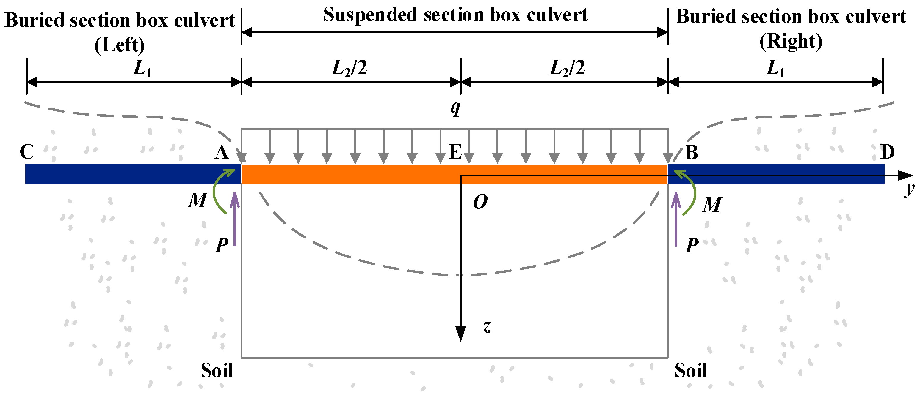
To analyze the mechanical behavior of unsupported box culverts, we establish a full-span mechanical model as shown in Figure 4. The model configuration includes:
  • Point O as the midpoint and coordinate origin of the suspended section;
  • Segments AC and BD represent left and right buried sections with length L1;
  • Segment AB is the suspended span with length L2.
The system considers the soil reactions at both ends, generating fixed-end support through bending moment, M, and shear force, P.
(1)
Vertical deformation of the buried section
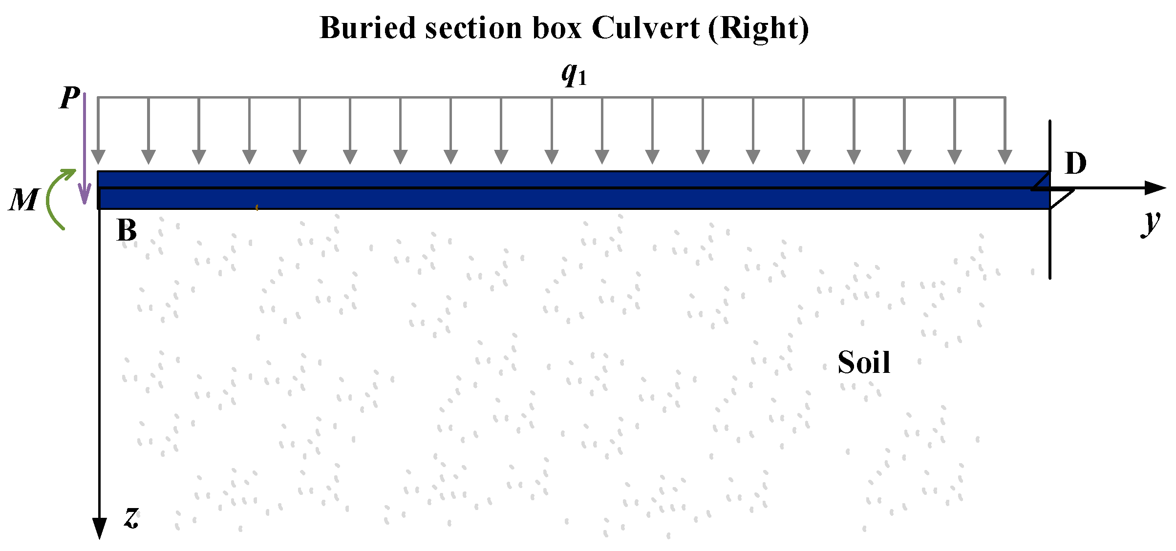
Figure 5 shows the mechanical model of the buried-section box culverts. For the segment BD ( L 2 2 y L 1 ), the self-weight of buried-section box culverts is regarded as a uniformly distributed load q1. Position B designates the interface between the suspended and buried section, where the interface bending moment M and shear P.
Based on the Winkler elastic foundation beam theory [43], the buried segment is treated as a semi-infinite elastic foundation beam. Its deflection control equation can be expressed as:
E I d 4 z d y 4 = q ( y ) p ( y )
where EI designates the bending stiffness of the box culverts, p(y) designates the foundation reaction force, which can be further determined by the following formula:
p ( y ) = k z = k 0 D z
where k0 designates the stiffness coefficient, which is determined by testing, and D designates the width of the box culverts.
By combining Equations (1) and (2), we can obtain:
E I d 4 z d y 4 + k z = q ( y )
Defining the box culvert characteristic coefficient as β = k 4 E I 4 , Equation (3) can be simplified to:
d 4 z d y 4 + 4 β 4 z = q ( y ) E I
The deformation z(y) for the buried box culvert section can be expressed as:
z ( y ) = e β y ( C 1 cos β y + C 2 sin β y ) + e β y ( C 3 cos β y + C 4 sin β y ) + q ( y ) k
where C1, C2, C3, and C4 are undetermined coefficients applicable (only for the derivation in this part) and can be determined through boundary conditions.
① The deformation at the right-hand end of the buried section ( y ) is zero, we can obtain:
z ( ) = 0
The above equation is satisfied only when C1 = 0, C2 = 0.
② The boundary condition at the left end of the box culvert (y = 0) is:
M | y = 0 = M q | y = 0 = P
From Equation (5), we can obtain:
M = E I d 2 z d y 2 = E I β 2 e β y [ 2 C 3 sin β y 2 C 4 cos β y ] q = E I d 3 z d y 3 = E I β 3 e β y [ 2 ( C 3 + C 4 ) cos β y + 2 ( C 3 + C 4 ) sin β y ]
Then, C3, C4 can be derived as follows:
C 3 = 2 β ( P M β ) k , C 4 = 2 β 2 M k
Thus, the vertical deformation formula of the box culvert in the local coordinate system is:
z ( y ) = 2 β k e β y ( P M β ) cos β y + M β sin β y + q 1 k
(2)
Vertical deformation of the suspended section
Figure 6 shows the mechanical model of the suspended-section box culverts. For the segment AB ( L 2 2 y L 2 2 ), the self-weight of suspended-section box culverts is regarded as a uniformly distributed load q. Position A designates the interface between the suspended and buried section, where the interface bending moment M and shear P are defined.
The deflection control equation can be expressed as:
E I d 4 z d y 4 = q ( y )
The bending moment formula for the beam can be expressed as:
M ( y ) = q L 2 y 2 q y 2 2 + M
The deformation formula can be obtained by integrating the bending moment equation twice, which is expressed as:
z ( y ) = 1 E I ( q L 2 12 y 3 q y 4 24 + M y 2 2 + C 1 y + C 2 )
where C1, C2 are undetermined coefficients (applicable only for the derivation in this part).
The boundary conditions at interface A (y = 0) and interface B (y = L2) are
z ( 0 ) = 0 z ( L 2 ) = 0
Then, C1 and C2 can be derived as follows:
C 1 = q 2 L 2 4 24 M L 2 2 2 , C 2 = 0
Thus, the vertical deformation formula for the suspended section of the box culverts in the local coordinate system is:
z ( y ) = y 6 E I ( 3 M L 2 + q L 2 3 4 3 M y q L 2 2 y 2 + q 4 y 3 )
(3)
Vertical deformation formulas for the full-span
Upon having derived the vertical deformation formulas for the suspended section and the buried section in their respective local coordinate systems, it is necessary to perform a coordinate transformation to integrate the deformations of all sections into a unified global coordinate system.
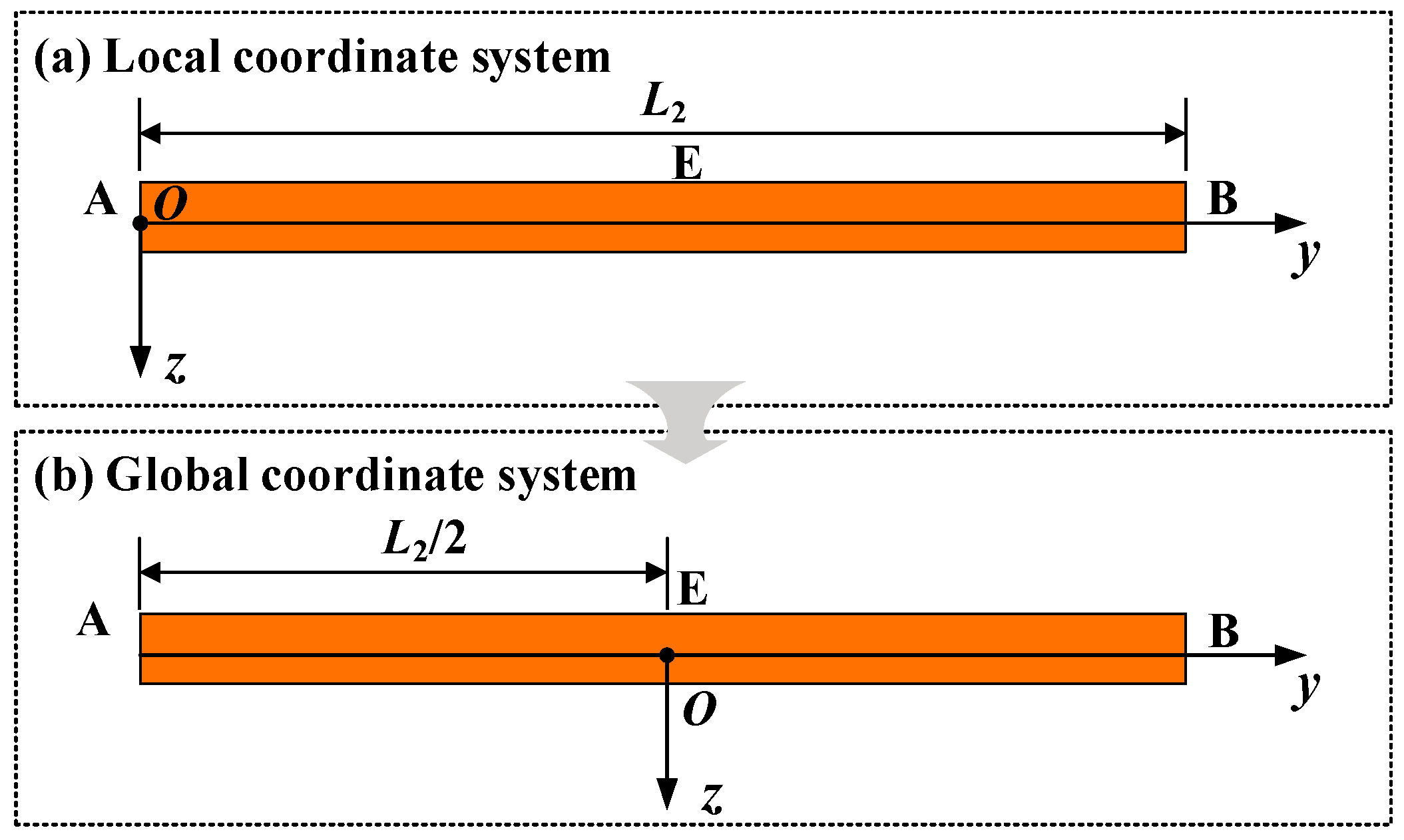
As shown in Figure 7, in the local coordinate system, the origin is located at position B, whereas in the global coordinate system, the origin is set at position E. Given that the distance between points E and B is L2/2, the coordinate transformation can be expressed as:
y global = y local L 2 2
where yglobal is the coordinate relative to position B, and ylocal is the coordinate relative to the global origin at position E.
Thus, the vertical deformation formula of the buried section in the global coordinate system can be expressed as:
z ( y ) = 2 β k e β ( y L 2 2 ) ( P M β ) cos β ( y L 2 2 ) + M β sin β ( y L 2 2 ) + q 1 k
As shown in Figure 8, in the local coordinate system, the origin is located at position A, whereas in the global coordinate system, the origin is set at position E. Given that the distance between points E and A is L2/2, the coordinate transformation can be expressed as:
y global = y local + L 2 2
where ylocal is the coordinate relative to position A, yglobal is the coordinate relative to the global origin at position E.
Thus, the vertical deformation formula of the suspended section in the global coordinate system can be expressed as:
z ( y ) = y + L 2 2 6 E I 3 M L 2 + q L 2 3 4 3 M ( y + L 2 2 ) q L 2 2 ( y + L 2 2 ) 2 + q 4 ( y + L 2 2 ) 3 + 2 β k ( P M β ) + q 1 k
where P = q 2 L 2 2 can be obtained from the vertical force equilibrium. From the deformation coordination at the connection point of the two sections of box culverts, it can be concluded that:
z ( 0 ) = z ( L 2 ) , θ ( 0 ) = θ ( L 2 )
Bending moment M can be sorted as:
M = q L 2 ( 12 + β 2 L 2 2 ) 24 β ( 2 + β L 2 )
Associated with Equations (18) and (20), and integrated with Equation (22), the vertical deformation of the entire box culverts can be expressed as:
z ( y ) = 2 β k e β ( y + L 2 2 ) q 2 L 2 2 + q 2 L 2 ( 12 + β 2 L 2 2 ) 24 β ( 2 + β L 2 ) β cos β ( y L 2 2 ) q 2 L 2 ( 12 + β 2 L 2 2 ) 24 β ( 2 + β L 2 ) β sin β ( y L 2 2 ) + q 1 k , L 1 y L 2 2 y + L 2 2 6 E I q 2 L 2 2 ( 12 + β 2 L 2 2 ) 8 β ( 2 + β L 2 ) + q L 2 3 4 + 3 q 2 L 2 ( 12 + β 2 L 2 2 ) 24 β ( 2 + β L 2 ) ( y + L 2 2 ) q 2 L 2 2 ( y + L 2 2 ) 2 + q 2 4 ( y + L 2 2 ) 3 + 2 β k β q 2 L 2 ( 12 + β 2 L 2 2 ) 24 β ( 2 + β L 2 ) + q 2 L 2 2 + q 1 k , L 2 2 y L 2 2 2 β k e β ( y L 2 2 ) q 2 L 2 2 + q 2 L 2 ( 12 + β 2 L 2 2 ) 24 β ( 2 + β L 2 ) β cos β ( y L 2 2 ) q 2 L 2 ( 12 + β 2 L 2 2 ) 24 β ( 2 + β L 2 ) β sin β ( y L 2 2 ) + q 1 k , L 2 2 y L 1

3.1.2. Case Study

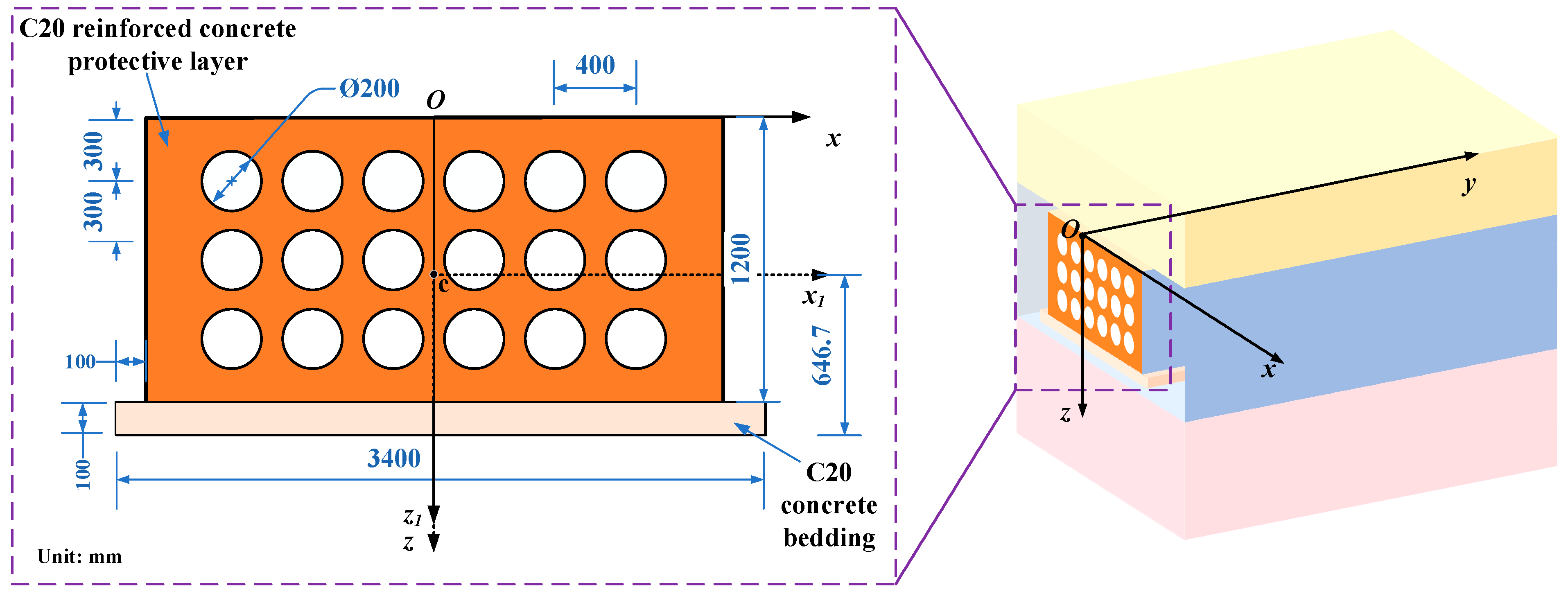
The 6-circuit 110 kV power cable mentioned above serves as the case study for deformation analysis. The maximum allowable unsupported span of the box culverts under unprotected conditions is calculated by Equation (23). For analysis, as shown in Figure 9, we established a three-dimensional coordinate system featuring a cross-section with 3400 mm total width and 1200 mm height, where point c marks the centroid position. As shown in Table 2, the calculated section modulus is W = 0.65 m3, and the moment of inertia is I = 0.56 m4. The combined weight of the protection layer and the pipeline is converted into a uniformly distributed load of q = 129.6 kN/m, with an elastic modulus of E = 1  GPa.
According to the <Technical specification for monitoring measurement of urban rail transit engineering in Jiangsu province> [44], the vertical deformation of pipelines exceeding 0.02 m is defined as a hazardous state. By substituting the data from Table 2 into Equation (23), given that the maximum settlement occurs at position E in Figure 4, which leads to the formulation of the following inequality:
z 0 = L 2 6.72 × 10 9 × 2777136 L 2 2 1134 L 2 4 2 + 0.07 × L 2 + 3.24 × 10 4 × L 2 3 + 1388568 L 2 + 567 L 2 4 2 + 0.07 × L 2 1.62 × 10 4 × L 2 4 + 4.05 × 10 3 × L 2 3 0.02
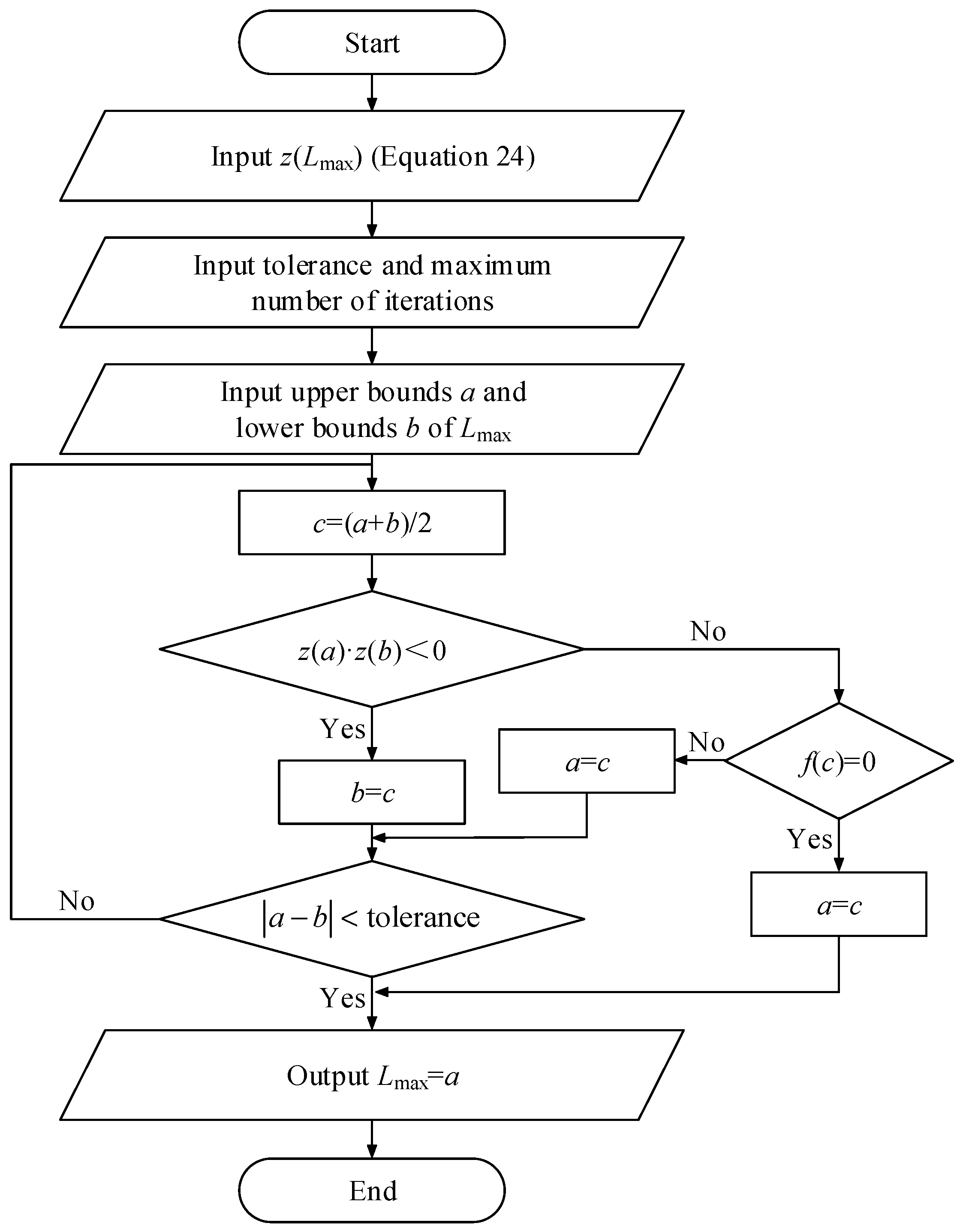
As the equation is a higher-order nonlinear one, we employed MATLAB (v2021a) to solve for L2. The programming flowchart is shown in Figure 10. The maximum unsupported span is calculated to be 7.7 m. Although previous analysis has neglected horizontal deformation and axial forces, a parametric study (as detailed in Appendix A) was further conducted to validate the rationality of this assumption by considering the effects of temperature-induced axial forces on vertical deformation.
The maximum unsupported span is calculated to be 7.7 m; however, the overhanging power box culvert extends 112 m in the practical project, necessitating the installation of protection. Considering the pipelines in this case cannot be relocated, in situ protection measures for the partially suspended sections are suitable. The following sections will analyze the support protection and the suspension protection, ultimately proposing an optimal protection scheme.

3.2. Vertical Deformation of the Box Culverts Under Protection

In this section, the vertical deformation formula of the box culverts under in situ protection is proposed. Based on the specification requirements, the maximum spacing between support points is further determined, and the support protection design for the box culverts is ultimately presented.
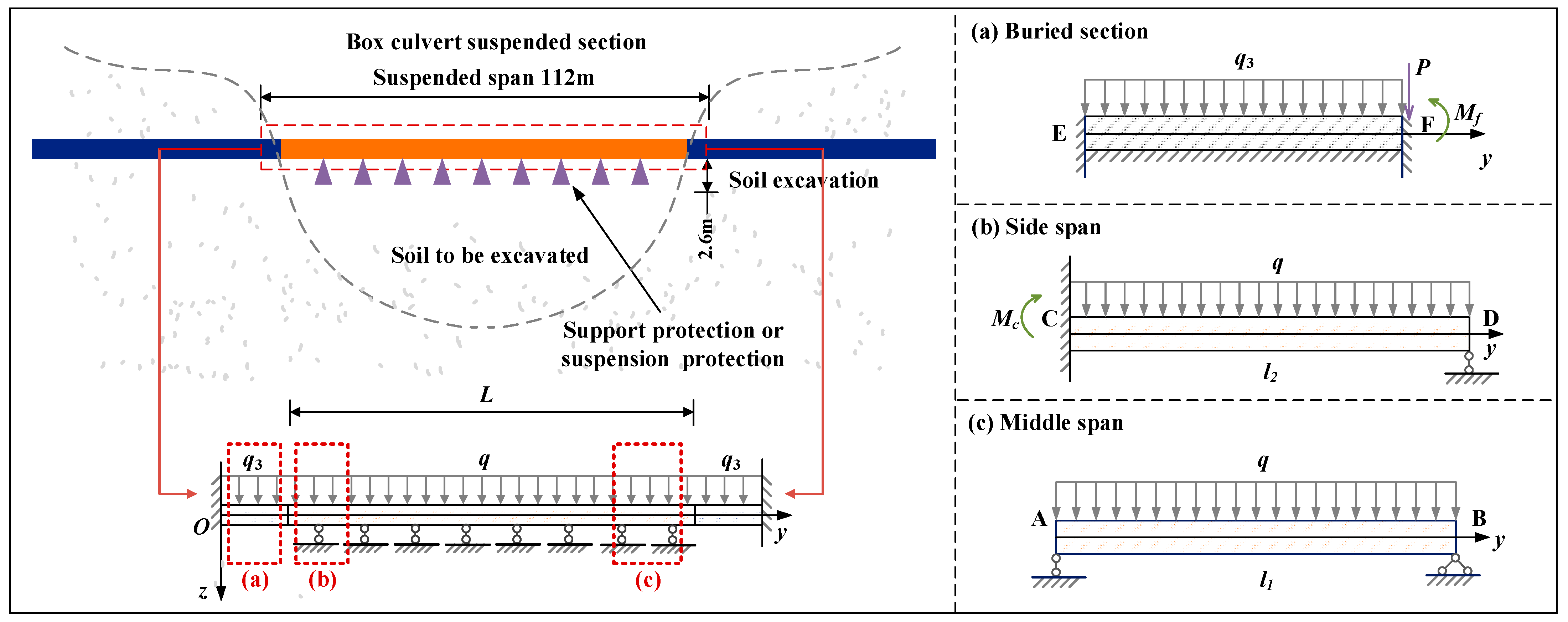
The total length of the box culverts can be divided into three sections: the buried section, the side span section, and the mid-span section. The buried section is embedded in the soil, where horizontal relative displacement with the soil is neglected, and it only follows the vertical settlement deformation of the soil, modeled as a semi-infinite beam on a Winkler foundation [43]. Considering the support or suspension protection system used in practical projects exhibits substantial stiffness with negligible deformation. The side span section is treated as a single-span beam with one end fixed and the other end simply supported. The mid-span section is modeled as a multi-span continuous beam with both ends simply supported. The self-weight of the suspended and buried sections of the box culvert is modeled as uniformly distributed loads q and q3, respectively.
Figure 10 shows the mechanical model of the box culverts under in situ protection.
(1) As shown in Figure 11a, for the segment EF, position F designates the interface between the suspended and buried section, where the interface bending moment Mf and shear P are defined.
According to Equation (10), the vertical deformation of the buried section is expressed as:
z ( y ) = 2 β k ( P M f β ) + q 3 k
where Mf is derived from the rotational compatibility condition at the interface F, which is expressed as:
M f = 48 E I P β 2 q 3 k l 2 3 8 ( 12 E I β 3 + l 2 k + 6 E I β 2 )
(2) As shown in Figure 11b, segment CD has a length of l2. Position C designates the interface between the side span and buried section, where the interface bending moment Mc is defined.
The vertical deformation formula for the side span section is expressed as:
z ( y ) = q 2 E I ( y 4 12 l 2 y 3 6 ) + M c y 3 6 E I l 2 M c y 2 2 E I + C 1 y + C 2
where C1, C2 are undetermined coefficients applicable (only for the derivation in this part) and can be determined through boundary conditions.
The boundary conditions at interface C (y = 0) and interface D (y = L2) are:
z ( 0 ) = 2 β k ( P M c β ) + q 3 k z ( l 2 ) = 0
Then, C1, C2 can be derived as follows:
C 1 = ( M c l 2 3 E I + q l 2 3 24 E I z 0 l 2 ) , C 2 = 2 β k ( P M f β ) + q 3 k
Thus, the vertical deformation formula for the side span section is:
z ( y ) = M c y 3 6 E I l 2 M c y 2 2 E I + q 2 E I ( y 4 12 l 2 y 3 6 ) + ( M c l 2 3 E I + q l 2 3 24 E I z 0 l 2 ) y + 2 β k ( P M f β ) + q 3 k
(3) As shown in Figure 11c, segment AB has a length of l1. The deformation formula of the middle span can be expressed as:
z ( y ) = q l 1 3 y 24 E I q l 1 y 3 12 E I + q y 4 24 E I
(4) The technical specification permits a maximum vertical deformation of z max for pipeline box culverts, the vertical deformation equations for each segment satisfy z m ( x ) z max , z s ( x ) z max , and then the maximum unsupported lengths of the middle span l m and the maximum unsupported lengths of the side span l s can be obtained. The full-span vertical deformation formula is expressed as:
z ( y ) = M c y 3 6 E I L M c y 2 2 E I + q c 2 E I ( y 4 12 l s y 3 6 ) + ( M c L 3 E I + q l s 3 24 E I 2 β l s k ( P M f β ) + q l s k ) y + 2 β k ( P M f β ) + q 3 k , 0 y < l s q l m 3 ( y l s n l m ) 24 E I q l m ( y l s n l m ) 3 12 E I + q ( y l s n l m ) 4 24 E I , l s < y L , n N
Thus, the full-span vertical deformation formula for the box culverts under in situ protection, when combined with the actual project parameters, enables the complete calculation of vertical deformation across the culvert span.

3.3. Support Protection and Suspension Protection for Box Culverts and Scheme Comparison

3.3.1. Support Protection for the Box Culverts

For the practical engineering case of the 112 m overhanging power box culverts at Yunnan Road Station discussed in Section 3.1, according to the <Technical specification for monitoring measurement of urban rail transit engineering in Jiangsu province> [44], a vertical deformation exceeding 0.02 m is considered hazardous for pipeline box culverts. Using the calculation parameters provided in Table 2 and applying Equation (32), the maximum allowable support spacing is determined to be 9.0 m for the mid-span section and 8.5 m for the side-span section. While the results presented herein are based on the idealized assumption of the simply supported model, the compliance of supports is a critical factor in practical engineering. Specifically, the sensitivity of the support spacing to the final joint stiffness must be considered. To address this, we have included a detailed analysis in Appendix B, which utilizes a specific case study to validate the rationality of our initial modeling assumptions.
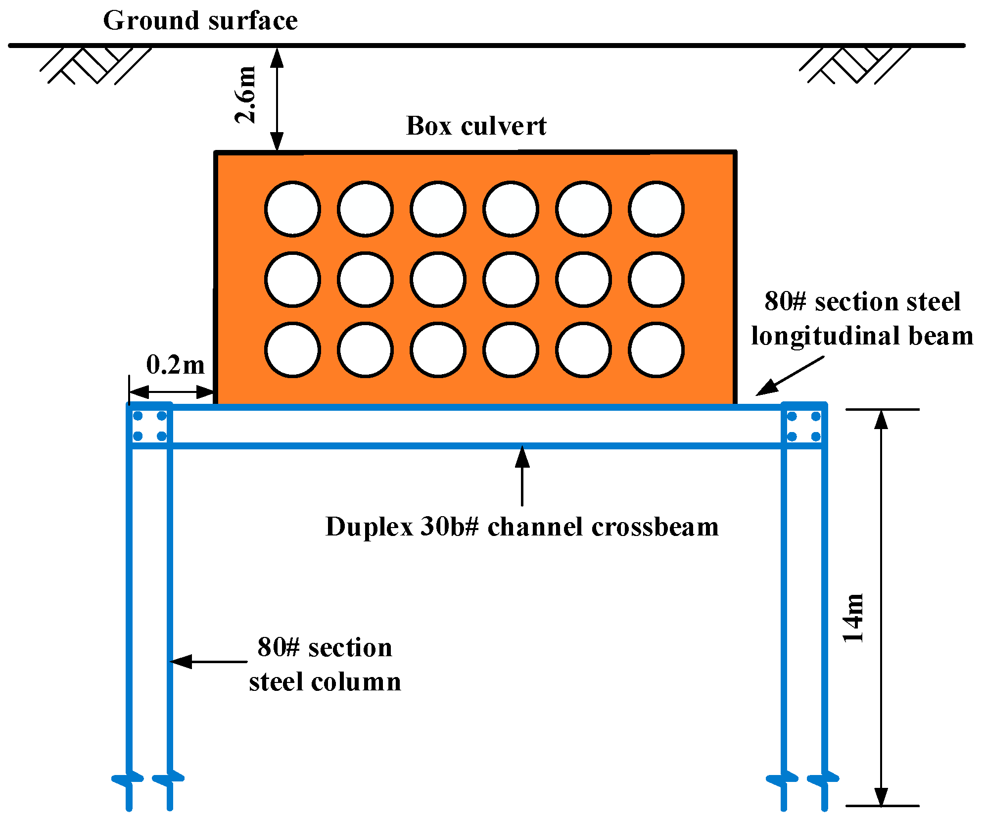
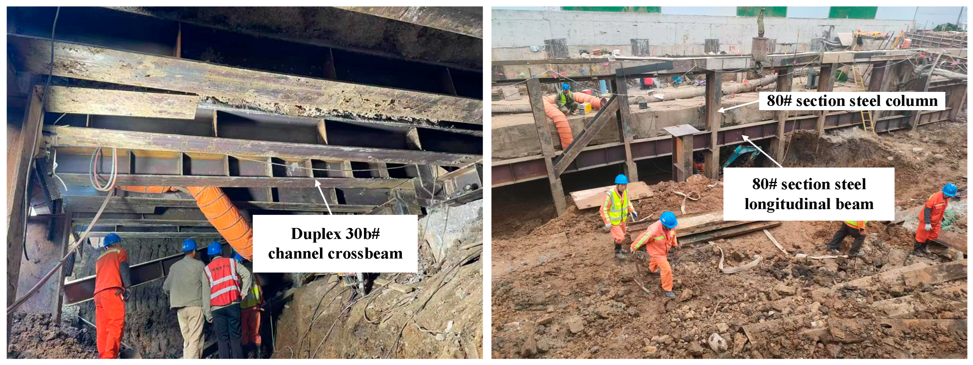
As shown in Figure 12, when the 6-circuit 110 kV pipeline box culverts are protected by the support method, the support structure consists of 80# section steel longitudinal beams and 80# section steel columns, forming a rigid frame structure beneath the suspended span to directly transfer loads to the stable stratum. To ensure sufficient engineering safety margin and to avoid differential settlement between the side-span and mid-span sections of the pipeline, the support protection design was configured as follows: side-span supports are positioned 8 m from the soil entry point (corresponding to 1.76 mm vertical deformation), and mid-span supports are spaced at 8.73 m (corresponding to 1.73 mm vertical deformation). This configuration divides the full span into 13 overhanging segments, requiring 12 support points in total.

3.3.2. Suspension Protection for the Box Culverts

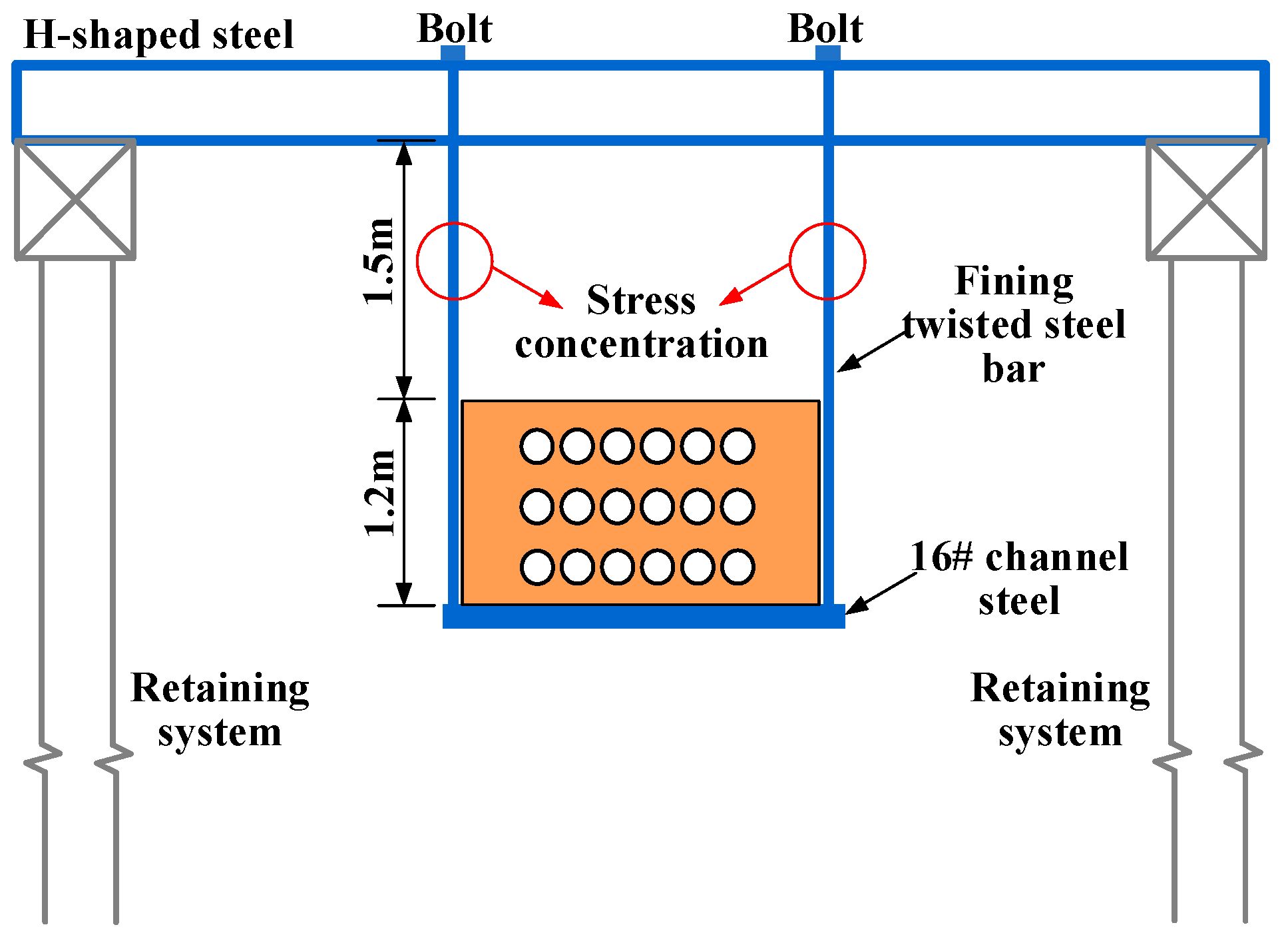
The calculation of pipeline box culverts’ deformation under suspension protection is the same as that under support protection. However, special attention should be paid to stress control in the suspension structure. When the 6-circuit 110 kV pipeline box culverts are protected by the suspension measure, the suspension structure consists of double H-shaped steel, steel wire ropes, channel steel, a concrete capping beam, and a retaining system of bored cast-in-place piles. As the soil beneath the power pipeline is excavated, the weight load of the 6-circuit 110 kV power corridor is transferred through the channel steel, wire ropes, and double H-shaped steel to the concrete capping beam. The capping beam then distributes the load to the bored cast-in-place piles, which ultimately transfer it to the foundation. A schematic diagram of the box culvert pipeline under suspension protection is shown in Figure 13.
The double H-shaped steel (upper beam) is placed on the ring beam of the foundation pit retaining structure to serve as the load-bearing system. Then, double 300 × 300 H-shaped steel beams are longitudinally installed on top of the upper beam, serving as the bridge frame (upper longitudinal beam). To ensure full contact between the steel wire ropes and the box culverts, 16# channel steel is used to support the bottom of the culvert during protection, followed by overall bundling and reverse suspension with 24 mm diameter steel wire ropes.
When the suspension protection is employed, excessive stress in the tensioned steel wire ropes may cause deformation or even failure, triggering a chain reaction that could ultimately lead to fracture of the power pipeline. Therefore, ensuring that the stress in the steel wire ropes remains within the allowable range is the primary concern in suspension protection. The allowable stress [ σ ] for the adopted 24 mm diameter steel wire rope is 31.58 MPa, with a safety factor of 5 applied, with reference to [45].
To ensure the stress safety of the suspension structure, the length of each mid-span section:
l n 4 S [ σ ] q
where ln is the length of each mid-span section; S is the cross-sectional area of the 24 mm diameter steel wire rope; q is the self-weight of the box culverts, equivalent to a uniformly distributed load.
By substituting q = 129.6 kN/m into Equation (33), the following result is obtained: l n 0.39 m , the minimum distance between each suspension point in the mid-span section is determined to be 0.39 m, indicating that a total of 285 suspension support points need to be set.

3.3.3. Optimal Protection Scheme for the Box Culverts

Based on the completed calculations and detailed design proposals for both the suspension protection and the support protection, a comparative analysis is presented in Table 3. The comparison covers key aspects, including the arrangement of protection points, spacing between points, cost, and required construction space.
In summary, the suspension protection offers advantages such as simple procedures, rapid implementation, and lower costs, making it suitable for protecting pipelines with small spans. However, it carries certain risks when applied to long-span suspended pipelines. In contrast, the support protection provides more reliable performance and is better suited for protecting pipelines with large spans, significant self-weight, and strict deformation control requirements. Additionally, it requires less construction space. Therefore, the support protection scheme is more suitable for pipeline protection at Yunnan Road Station compared to the suspension protection.
Following this conclusion, the support protection method was selected and implemented in the actual construction at Yunnan Road Station. Figure 14 shows key components such as the columns, longitudinal beams, and the overall support system, which are provided as evidence of the practical application and execution of the designed scheme.

4. Results

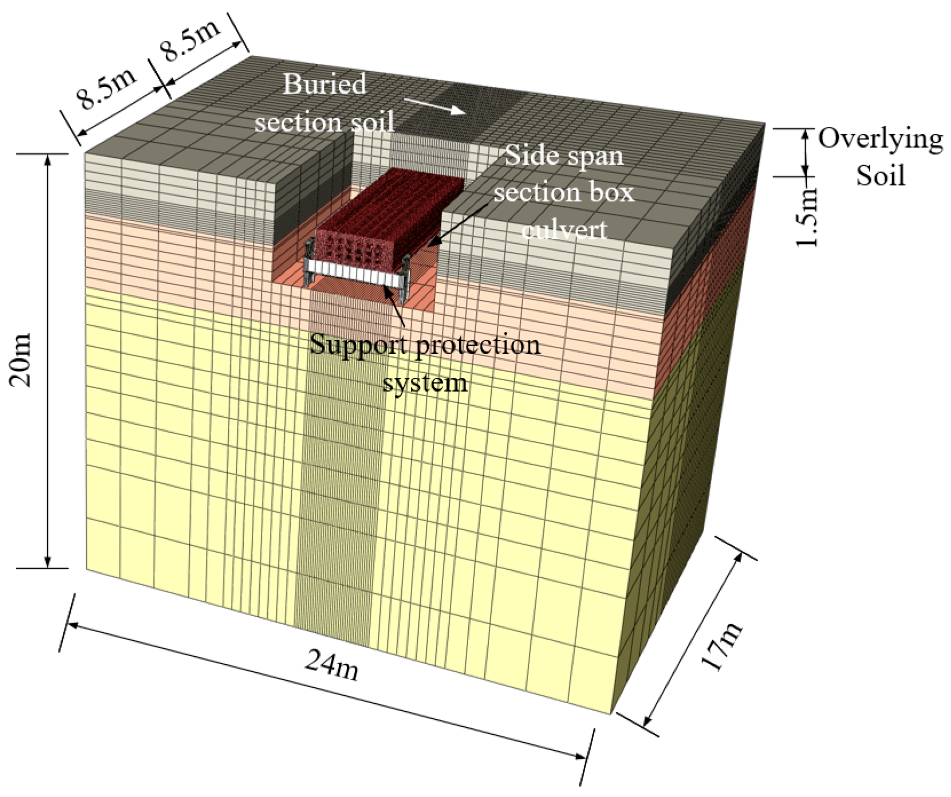
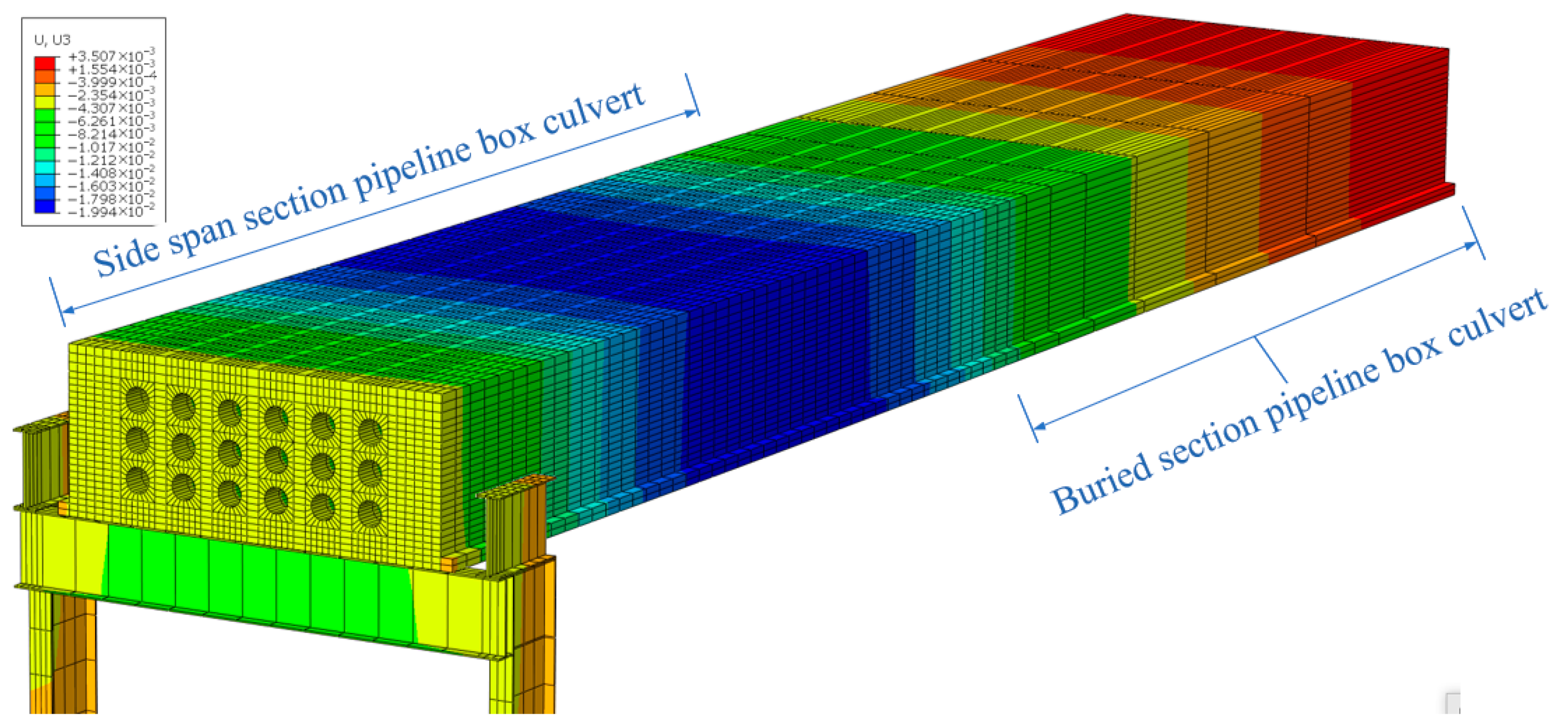
To validate the accuracy of the full-span vertical deformation calculation formula for the box culverts under support protection, we established a three-dimensional finite element model of the soil-culvert-support system using ABAQUS/Explicit v2016, simulating the side-span support scheme (as shown in Figure 15). The model dimensions include a 17 m longitudinal length (8.5 m side span + 8.5 m buried section), a width of 6 times the culverts’ width, and a 24 m length with 20 m soil depth to eliminate boundary effects. The soil, culverts, and support system employ three-dimensional solid elements connected via tie constraints, while the steel columns are simplified as discrete rigid bodies embedded in the soil. The Mohr-Coulomb ideal elastic-plastic model governs the soil behavior. The boundary conditions are specifically as follows: full constraint at the base, lateral normal displacement restriction, and a free upper surface. A structured mesh with local refinement near the side-span and buried sections, combined with hourglass control, ensures computational precision. Based on the ground survey report and material parameters provided on site, the modeled component properties are shown in Table 4. The numerical modeling procedure consisted of the following sequential stages: geostatic stress equilibrium, activation of the support system, and deactivation of soil elements to simulate excavation.
Iterative trial calculations confirmed negligible soil excavation effects on mid-span deformation at a magnitude of 10−5, validating the exclusion of soil in subsequent modeling. A three-dimensional numerical model of the support system and 9 m mid-span section was developed, as shown in Figure 16. The model employed solid elements for the power box culvert, 80# section longitudinal beams, and channel beams, while section columns were treated as discrete rigid bodies due to their minimal deformation. Tie constraints connected all components, with fully fixed boundary conditions at column bases. The mesh consisted of structured hexahedral eight-node (C3D8) elements with local refinement and hourglass control implementation.
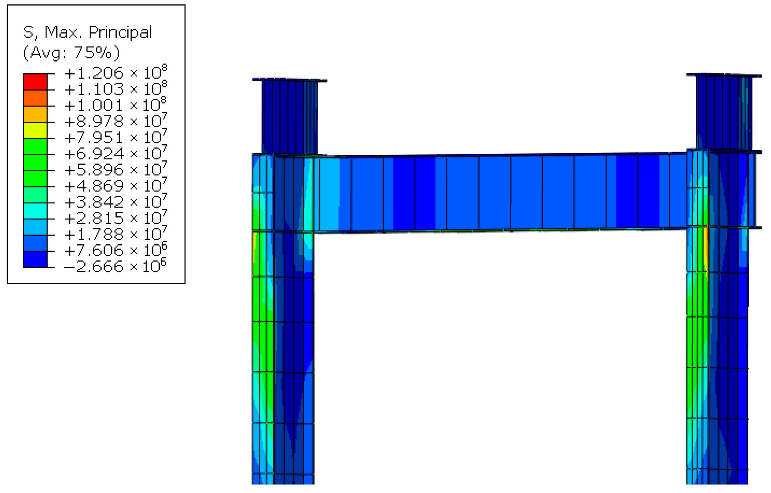
Numerical analysis of the box culvert-support system reveals the stress–strain distribution, with Figure 17 showing maximum stress concentrations (120.60 MPa) occurring at the crossbeam-longitudinal beam connection in the side span section. This stress level remains significantly below the 315 MPa allowable limit for 80# section steel, confirming structural integrity. Figure 18 further indicates a maximum box culvert deformation of 19.9 mm, according to the <Technical specification for monitoring measurement of urban rail transit engineering in Jiangsu province> [44], the pipeline deformation complies with all safety requirements.
Owing to complex site conditions yielding discrete measurements and precluding continuous deformation data collection, as shown in Figure 19, theoretical and simulated vertical displacements for the side-span section were comparatively assessed. At 3.8 m spacing between the support point and soil entry point, the theoretical maximum displacement is 19.9 mm, and the simulated results are 20.0 mm, showing close agreement, while the field-measured deformation approximates 17.3 mm. The theoretical and numerical simulation results both comply with the specification requirement of 20 mm for deformation.
Settlement y0 initiates at the culvert terminus (x = 0 m), propagating along the longitudinal axis and inducing systemic vertical displacement amplification. Maximum displacement occurs at x = 3.8 m, reducing to 2.5 mm at x = 8.5 m, where simulated displacement comprises the cumulative effect of support system deformation under culvert loading and soil displacement.
Numerical modeling generated comprehensive stress-displacement contours illustrated in Figure 20. Analysis reveals maximum support system stress occurs at the longitudinal beam-channel beam interface, with a principal stress value of 206.4 MPa—significantly below the 930 MPa material capacity. Displacement contours similarly indicate a maximum box culvert deformation of 16.9 mm, which is below the 20 mm limit stipulated by the specification. Therefore, a support spacing of 9 m for the mid-span section satisfies all stress and deformation requirements.
Figure 21 shows a comparative analysis of theoretical and numerical vertical deformation results for the box culvert. The theoretical model, based on Equation (32), predicts a maximum displacement of 20.0 mm, which slightly overestimates the field-measured value of 18.7 mm and the numerically simulated result of 16.9 mm. This consistent overestimation, while maintaining compliance with specification limits, demonstrates the conservative nature of the theoretical approach and provides a valuable safety margin for engineering design.
To sum up, the tendency of both the analytical and numerical models to yield slightly conservative predictions compared to field measurements can be attributed to the intentional and inherent simplifications in the modeling process. Firstly, the models are designed to provide a safe upper-bound estimate by neglecting certain secondary stiffening effects present in the actual structure. These include the composite action with internal non-structural components (e.g., cable bundles and their supports) and the semi-rigid behavior of connections in the field, both of which contribute additional, unquantified stiffness that reduces overall displacement. Secondly, the selection of input parameters, particularly the use of a conservative value for the elastic modulus of the reinforced concrete box culvert, ensures that the analysis remains on the safe side for design purposes. Consequently, this conservative discrepancy does not detract from the model’s accuracy but rather validates its reliability as a practical and safe tool for deformation control design, providing a built-in safety margin that accounts for unforeseen favorable site conditions and unmodeled structural contributions.

5. Discussion

The preceding analysis demonstrates that as the suspended length increases, the shear force P and bending moment M at the buried section gradually increase, leading to a corresponding growth in the terminal settlement z0. Soil-derived settlement substantially contributes to overall vertical displacement, particularly within soft-soil regions such as the Yangtze River Delta and Pearl River Delta, where settlement magnitudes are amplified [46,47]. Consequently, controlling terminal settlement constitutes a critical consideration for managing global box culvert displacement. In addition to in situ support measures, soil reinforcement also proves highly effective in controlling vertical displacement [48]. Therefore, this study proposes a combined approach of installing supports in the suspended span and reinforcing the soil in the embedded sections to more effectively control vertical displacement, and further investigates the performance of soil reinforcement treatments.
Using Yunnan Road Station as a case study, as shown in Table 5, this analysis investigates the sensitivity of reinforcement scope and reinforcement strength by simulating various soil reinforcement schemes for the buried section of the culvert.
Scheme 1 compares the control effectiveness of reinforcement soil depth on the vertical deformation of the buried pipeline. Reinforcement depths are selected as one, three, six, and nine times the culvert’s height h. The vertical displacement of the box culverts under different reinforcement depths is shown in Figure 22a.
Scheme 2 compares the control effectiveness of reinforcement soil width on the vertical deformation of the buried pipeline. Reinforcement widths are selected as one, two, three, and four times the culvert’s width b. The vertical displacement of the box culverts under different reinforcement widths is shown in Figure 22b.
It is concluded that when the reinforcement area and material are fixed, greater reinforcement depth results in smaller overall vertical displacement of the box culvert. However, beyond a depth of 3h, the vertical displacement remains largely unchanged and shows no further reduction. As the reinforcement width increases, vertical displacement gradually decreases, but beyond three times the culvert width, the displacement stabilizes with no significant further reduction. Thus, for Yunnan Road Station, critical thresholds for reinforcement depth and width are identified as 3h and 3b, respectively. Exceeding these limits provides negligible additional reduction in vertical deformation.
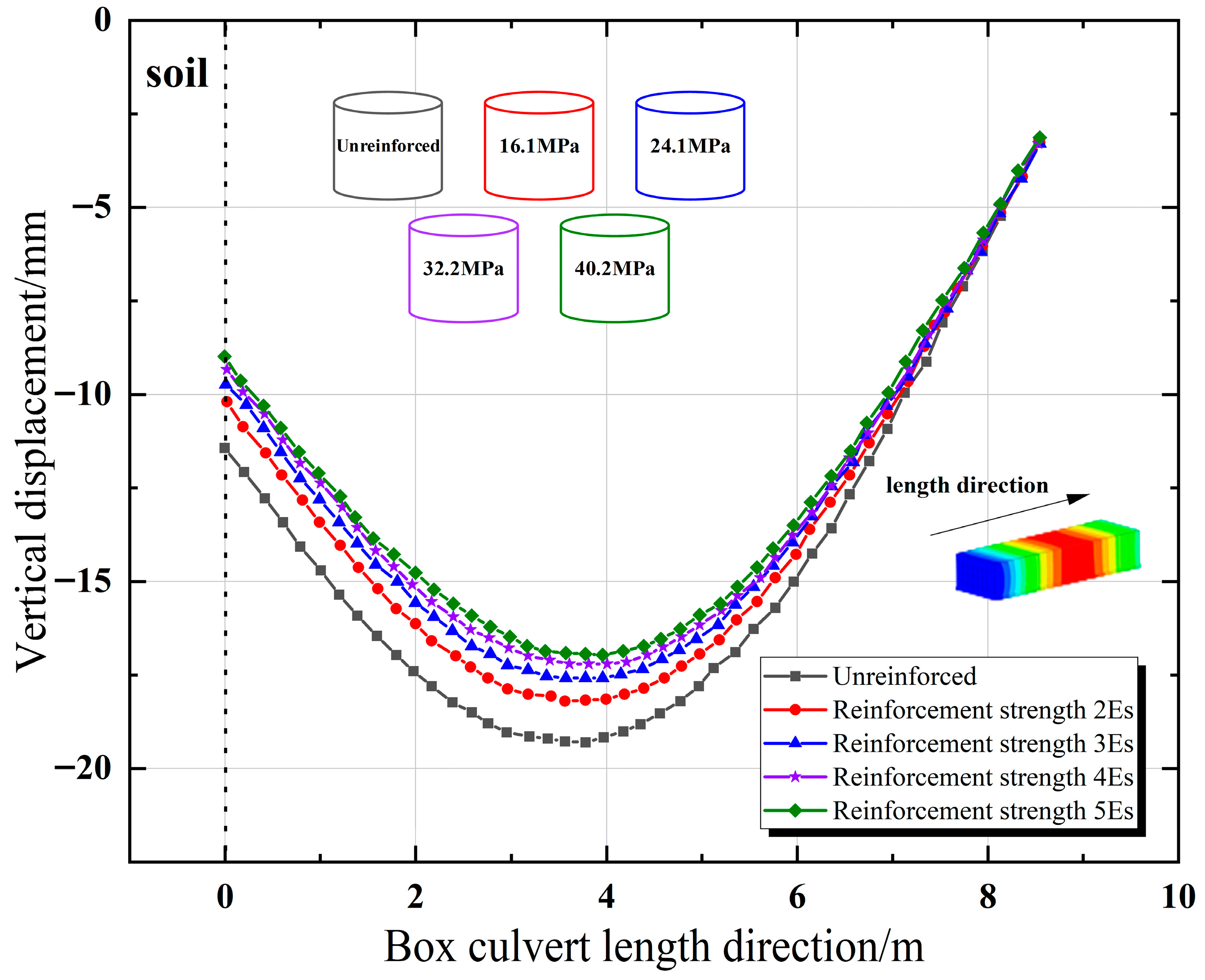
Scheme 3 compares the control effectiveness of reinforcement strength on the vertical deformation of the buried pipeline. The vertical displacements at the side span of the box culvert under different reinforcement strengths are shown in Figure 23. When the reinforcement scope is fixed, increasing the strength of the soil in the buried section effectively controls the vertical displacement of the box culvert. The control effect on terminal settlement is highly pronounced at reinforcement strengths of 2Es and 3Es, but beyond 3Es, the improvement diminishes gradually.

6. Conclusions

This study systematically investigates the deformation control of large-span buried box culverts subjected to excavation, focusing on both unsupported and supported conditions. The main conclusions are as follows:
  • A full-span mechanical model was established by dividing the box culvert into buried, side-span, and mid-span sections. Analytical solutions for vertical deformation under both unprotected and protected conditions were derived, enabling the determination of critical engineering parameters such as the maximum allowable unsupported span and the optimal support spacing.
  • Taking the 112 m overhanging power box culvert at Yunnan Road Station as a case study, the results indicate that the culvert cannot remain stable under unsupported conditions, requiring in situ protection. The analytically derived support scheme—specifying optimized spacings of 8.5 m (side-span) and 9.0 m (mid-span) with twelve support points—validates the model’s practical utility while maintaining an inherent safety margin.
  • Comprehensive validation through three-dimensional ABAQUSs confirms both the accuracy and engineering applicability of the proposed analytical method. The close agreement among theoretical predictions, numerical results, and field measurements establishes the method’s reliability for practical design applications.
  • Parametric analysis reveals that soil reinforcement effectively controls deformation, with a particularly significant finding being the identification of economic thresholds at approximately three times the culvert’s height (3h) and width (3b). This crucial insight enables optimized design by defining the point of diminishing returns for reinforcement investment.
  • Comparative analysis between support protection and suspension protection demonstrated that the support protection, despite higher initial costs, offers greater reliability and minimal deformation control for large-span culverts with strict safety requirements, making it more suitable for applications in complex urban environments such as the Yunnan Road Station project.
However, several limitations of the proposed analytical model should be acknowledged. First, the foundation behavior is simplified using the Winkler assumption, which does not explicitly account for soil consolidation and creep effects. This may lead to underestimated settlement predictions under long-term conditions. Second, the model treats the self-weight of the culvert, elastic modulus of concrete, and subgrade reaction coefficient as constants, whereas in reality, these parameters may vary due to concrete cracking, aging, or soil compaction and liquefaction. Third, the boundary conditions for the support system idealize the flexible lattice supports as rigid connections, neglecting the potential influence of rotational stiffness and vertical spring stiffness on moment redistribution. Despite these limitations, the simplified model provides a valuable theoretical framework and practical tool for preliminary design and parametric analysis. Future research will focus on incorporating time-dependent soil behavior, material nonlinearity, and flexible support conditions to develop more refined models that can capture complex interactions in practical engineering scenarios.

Author Contributions

Conceptualization, H.L. and X.Y.; methodology, X.Y., M.X. and Z.W.; software, X.Y. and D.H.; validation, Z.W., L.G. and P.X.; formal analysis, X.Y. and L.G.; investigation, D.H. and P.X.; resources, H.L.; writing—original draft preparation, X.Y. and L.G.; writing—review and editing, H.L. and M.X.; visualization, Z.W.; supervision, H.L. and D.H.; project administration, H.L.; funding acquisition, H.L. All authors have read and agreed to the published version of the manuscript.

Funding

This research was funded by the National Natural Science Foundation of China, grant number 5247084914 and Jiangsu Province Postgraduate Practical Innovation Program 2025, grant number SJCX25_0613.

Data Availability Statement

The original contributions presented in the study are included in the article; further inquiries can be directed to the corresponding author.

Conflicts of Interest

The authors declare no conflicts of interest.

Appendix A

The deflection control equation of the unsupported span, considering the influence of axial force N, can be expressed as:
E I d 4 z d y 4 + N d 2 z d y 2 = q ( y )
Then the vertical deformation formula for the suspended section of the box culverts in the local coordinate system is:
z ( y ) = y + L 2 2 6 E I 3 M L 2 + q L 2 3 4 3 M ( y + L 2 2 ) q L 2 2 ( y + L 2 2 ) 2 + q 4 ( y + L 2 2 ) 3 + 2 k 3 2 + N E I k 2 ( P M k 2 N 4 E I ) + q 1 k
The vertical deformation of the 7.7 m unsupported span was calculated separately for temperature increases of 10 °C and 20 °C, as well as for temperature decreases of 10 °C and 20 °C. The linear expansion coefficient for concrete was taken as 1 × 10⁻⁵/°C. The calculation results are presented in Table A1.
Table A1. Vertical deformation Considering Temperature Effects.
Temperature Change (°C)Axial Force
Condition (kN)
Maximum Vertical
Deformation (mm)
Relative Change (%)
−2083620.693.45
−1041820.321.60
0020.000
+10−41820.221.12
+20−83620.753.77
Tensile axial force is defined as positive, and compressive axial force as negative.
Based on the aforementioned calculation results, it can be concluded that within the temperature variation range of ±20 °C, the maximum relative change in vertical deformation induced by axial force is only 3.77%, indicating a limited magnitude of influence. Therefore, within the scope of engineering parameters focused on in the current study, neglecting the effect of axial force has a negligible impact on the accuracy of vertical deformation calculations, further demonstrating that this simplification is justified.

Appendix B

The calculation model with vertical springs was constructed and compared its results with those from the simplified model to further validate the reliability of the simplified approach.
Figure A1 presents the simplified model of the mid-span section supported by vertical springs, and its governing equation is:
E I z ( 4 ) ( y ) = q
The boundary conditions are:
z ( 0 ) = 0 z ( l 1 ) = 0 E I z ( 0 ) + k r z ( 0 ) = 0 E I z ( l 1 ) k r z ( l 1 ) = 0
The deformation formula of the middle span can be expressed as:
z ( y ) = q 24 E I y 4 l 1 q 12 E I y 3 + k r l 1 3 q 24 E I ( k r l 1 2 E I ) y 2 l 1 3 q 12 ( k r l 1 2 E I ) y
Figure A1. Vertical springs model of the box culverts under in situ protection.
Buildings 15 03804 g0a1
Stiffness values of vertical springs were selected as 0 and 104 to simulate ideal simply supported and vertical spring-supported conditions, respectively. By substituting the maximum mid-span spacing of 9.0 m and the data from Table 2 into Equation (A5) for calculation, the maximum settlement obtained using the vertical springs model was 20.93 mm, with an error of 4.65%. This deviation has a limited impact on the results and falls within the acceptable error range. Therefore, the use of the ideal simply supported model is justified.

References

  1. Liu, W.; Xue, D.; Yuan, J. Analysis of Influences Caused by Cantilever Pile-Supported Pit Excavation towards Adjacent Buried Pipe Lines. IOP Conf. Ser. Earth Environ. Sci. 2018, 153, 052028. [Google Scholar] [CrossRef]
  2. Jiang, N.; Gao, T.; Zhou, C.; Luo, X. Effect of Excavation Blasting Vibration on Adjacent Buried Gas Pipeline in a Metro Tunnel. Tunn. Undergr. Space Technol. 2018, 81, 590–601. [Google Scholar] [CrossRef]
  3. Sun, S.; Rong, C.; Wang, H.; Cui, L.; Shi, X. The Ground Settlement and the Existing Pipeline ResponseInduced by the Nonsynchronous Construction of a Twin-Tunnel. Adv. Civ. Eng. 2021, 2021, 8815304. [Google Scholar] [CrossRef]
  4. Avgerinos, V.; Potts, D.M.; Standing, J.R. Numerical Investigation of the Effects of Tunnelling on Existing Tunnels. Géotechnique 2017, 67, 808–822. [Google Scholar] [CrossRef]
  5. Meng, F.; Chen, R.; Xu, Y.; Wu, K.; Wu, H.; Liu, Y. Contributions to Responses of Existing Tunnel Subjected to Nearby Excavation: A Review. Tunn. Undergr. Space Technol. 2022, 119, 104195. [Google Scholar] [CrossRef]
  6. Zhang, Q.; Zhang, G.; Ding, X. Special Issue on Tunnel Construction and Underground Space Technology. Buildings 2023, 13, 2988. [Google Scholar] [CrossRef]
  7. Fu, D.; Deng, B.; Yang, M.; Zhen, B. Analytical Solution of Overlying Pipe Deformation Caused by Tunnel Excavation Based on Pasternak Foundation Model. Sci. Rep. 2023, 13, 921. [Google Scholar] [CrossRef]
  8. Zhang, C.; Zhu, J.; Huang, M.; Yu, J. Winkler Load-Transfer Analysis for Pipelines Subjected to Surface Load. Comput. Geotech. 2019, 111, 147–156. [Google Scholar] [CrossRef]
  9. Zhang, Z.; Zhang, M.; Zhao, Q.; Fang, L.; Ding, Z.; Shi, M. Interaction Analyses between Existing Pipeline and Quasi-Rectangular Tunneling in Clays. KSCE J. Civ. Eng. 2021, 25, 326–344. [Google Scholar] [CrossRef]
  10. Banushi, G.; Wham, B.P. Deformation Capacity of Buried Hybrid-Segmented Pipelines under Longitudinal Permanent Ground Deformation. Can. Geotech. J. 2021, 58, 1095–1117. [Google Scholar] [CrossRef]
  11. Jiang, T.; Xie, Z.; Wang, J.; Li, D.; Qu, C. A Novel Strain-Based Deformation Monitoring Method for Subsea Free-Spanning Pipelines. Eng. Struct. 2025, 343, 120998. [Google Scholar] [CrossRef]
  12. Wang, H.; Lei, Z.; Wang, Z.; Guo, Z. Analytical Models of High-Temperature Pipeline Deformation under Submarine Landslides. Thin-Walled Struct. 2025, 210, 112990. [Google Scholar] [CrossRef]
  13. Nie, H.; Ma, W.; He, X.; Huo, X.; Wang, Y.; Ren, J.; Dang, W.; Wang, K.; Cao, J.; Yao, T.; et al. Study on Buckling Deformation Mechanism of Pipeline Crossing Road. Eng. Fail. Anal. 2022, 139, 106412. [Google Scholar] [CrossRef]
  14. Wang, C.; Li, C.; Liu, W.; Wang, J.; Wu, J. Pipeline–Soil Separation Model for Natural Gas Pipelines Subjected to Parabolic Driving Force. J. Pipeline Syst. Eng. Pract. 2019, 10, 04018028. [Google Scholar] [CrossRef]
  15. Wang, X.; Yao, A. Deflection and Internal Force Analysis of Buried Steel Pipelines in Partial Hanging. Eng. Mech. 2008, 25, 218–222. [Google Scholar]
  16. Liang, L.; Xu, C.; Zhu, B.; Deng, J. Theoretical Method for an Elastic Infinite Beam Resting on a Deformable Foundation with a Local Subsidence. Comput. Geotech. 2020, 127, 103740. [Google Scholar] [CrossRef]
  17. Li, B.; Fang, H.; Zhai, K.; Yang, K.; Zhang, X.; Wang, Y. Mechanical Behavior of Concrete Pipes with Erosion Voids and the Effectiveness Evaluation of the Polyurethane Grouting. Tunn. Undergr. Space Technol. 2022, 129, 104672. [Google Scholar] [CrossRef]
  18. Liu, X.; Jiang, A.; Fang, Q.; Wan, Y.; Li, J.; Guo, X. Spatiotemporal Deformation of Existing Pipeline Due to New Shield Tunnelling Parallel Beneath Considering Construction Process. Appl. Sci. 2022, 12, 500. [Google Scholar] [CrossRef]
  19. Zhao, S.-W.; Li, X.-L.; Li, X.; Chen, L.-G.; Li, T.; Li, S.-H.; Bai, Y. Analysis of Pipeline Deformation Caused by Shield Tunnel Excavation That Obliquely Crosses Existing Pipelines. Arab. J. Geosci. 2022, 15, 227. [Google Scholar] [CrossRef]
  20. Wang, D.; Dong, J.; Chen, X.; Du, J.; Shu, D.; Krassowska, J. Influence of Gas Explosions in Utility Tunnels on the Structural Safety of Overhead Pipelines. Buildings 2025, 15, 3391. [Google Scholar] [CrossRef]
  21. Xu, Q.; Zhang, W.; Chen, C.; Lu, J.; Tang, P. Study on Settlement Influence of Newly Excavated Tunnel Undercrossing Large Diameter Pipeline. Adv. Civ. Eng. 2022, 2022, 5700377. [Google Scholar] [CrossRef]
  22. Zhou, X.; Chen, Q.; Jiang, B.; Chen, H. An Underground Pipeline Mapping Method Based on Fusion of Multisource Data. IEEE Trans. Geosci. Remote Sens. 2022, 60, 4511711. [Google Scholar] [CrossRef]
  23. Farh, H.M.H.; Ben Seghier, M.E.A.; Zayed, T. A Comprehensive Review of Corrosion Protection and Control Techniques for Metallic Pipelines. Eng. Fail. Anal. 2023, 143, 106885. [Google Scholar] [CrossRef]
  24. Liu, Y.; Jiang, M. Application of Suspension Protection Technology in Underground Pipe Gallery. Chin. J. Undergr. Space Eng. 2018, 14, 285–290. Available online: https://kns.cnki.net/kcms2/article/abstract?v=vfP_nAZksBLeiSBEI5K00j6RxdC5Yo5NHJVEH4zE-VCQr17rDVx_yoWgMY0C-EeJEKnDju2MUId6dRm2RHVdZIyQhXwofpIMStwZt2DSLHvwELUJMaGU6IWOe5GgSWkr-os0F7s4fU4NI-GrVIKX_6hwgBF3O-0Y9Owzl5Mlgz4=&uniplatform=NZKPT (accessed on 17 September 2025). (In Chinese).
  25. Meng, Z.; Wei, W.; Han, G.; Yu, Z.; Lu, J.; Wu, M.; Zhang, J.; Yu, J.; Jin, D. Research on Design and Construction Technology of Large Span T-Truss Suspension Beam. IOP Conf. Ser. Earth Environ. Sci. 2021, 804, 022092. [Google Scholar] [CrossRef]
  26. Yu, H.; Xu, F.; Ma, C.; Zhou, A.; Zhang, M. Experimental Research on the Aerodynamic Responses of a Long-Span Pipeline Suspension Bridge. Eng. Struct. 2021, 245, 112856. [Google Scholar] [CrossRef]
  27. Zeng, X.; Dong, F.; Xie, X.; Du, G. A New Analytical Method of Strain and Deformation of Pipeline under Fault Movement. Int. J. Press. Vessel. Pip. 2019, 172, 199–211. [Google Scholar] [CrossRef]
  28. Simão, M.; Mora-Rodriguez, J.; Ramos, H. Design Criteria for Suspended Pipelines Based on Structural Analysis. Water 2016, 8, 256. [Google Scholar] [CrossRef]
  29. Tschemmernegg, F.; Brändstatter, H. Austria’s Longest Pedestrian Suspension Bridge. Struct. Eng. Int. 1997, 7, 17–18. [Google Scholar] [CrossRef]
  30. Guo, P.; Sun, T.; Li, H.; Wang, Y. Performance of Pipeline Suspension System for In-Situ Protecting Large-Diameter Pressurized Pipelines Straddling Deep Braced Excavation in Clays. Tunn. Undergr. Space Technol. 2025, 163, 106752. [Google Scholar] [CrossRef]
  31. Guo, P.; Gong, X.; Wang, Y.; Lin, H.; Zhao, Y. Analysis of Observed Performance of a Deep Excavation Straddled by Shallowly Buried Pressurized Pipelines and underneath Traversed by Planned Tunnels. Tunn. Undergr. Space Technol. 2023, 132, 104946. [Google Scholar] [CrossRef]
  32. Zhang, J.; Xie, R.; Zhang, H. Mechanical Response Analysis of the Buried Pipeline Due to Adjacent Foundation Pit Excavation. Tunn. Undergr. Space Technol. 2018, 78, 135–145. [Google Scholar] [CrossRef]
  33. Liu, X.; Zhang, H.; Wu, K.; Xia, M.; Zheng, Q.; Ndubuaku, O.; Adeeb, S. Research Progress of Strain Analysis Methods for Buried Pipelines under Faulting Process. Oil Gas Storage Transp. 2016, 8, 799–807. [Google Scholar] [CrossRef]
  34. Tan, Y.; Lu, Y. Responses of Shallowly Buried Pipelines to Adjacent Deep Excavations in Shanghai Soft Ground. J. Pipeline Syst. Eng. Pract. 2018, 9, 05018002. [Google Scholar] [CrossRef]
  35. Wu, B.; Ge, C.; Li, P.; Yang, M.; Li, L. Influence of Deep Foundation Pit Excavation on Adjacent Pipelines: A Case Study in Nanjing, China. Appl. Sci. 2024, 14, 572. [Google Scholar] [CrossRef]
  36. Jiao, W.; Xu, J.; Tian, J.; Xie, X.; Du, G. Seismic Response Analysis of Buried Pipelines with the High Drop. Int. J. Press. Vessel. Pip. 2021, 191, 104379. [Google Scholar] [CrossRef]
  37. China Electric Power Press. Technical Specification for Thermal Power Erection and Construction—Part 5: Piping and System; DL 5190.5-2019; China Electric Power Press: Beijing, China, 2019. [Google Scholar]
  38. Liu, G.; Bai, Y.; Yao, L.; Cheng, Y.; Li, W.; Chang, L. Protection Construction Technique for Overhead 110 kVA Super-Long Power Lines. Archit. Technol. 2021, 52, 1292–1294. Available online: https://kns.cnki.net/kcms2/article/abstract?v=vfP_nAZksBI7M-j7pJhziGySk_DbhXjhLyhs4NCtsMC066bJMPZPkOSGRYD9_GkNWLifjtT-tzosMqb5EQjszhsaHxlLuYp365Q0sBk-L4ecvRB9-csBjBG94psygV1O37Q58XJiVgBFXT-dJeEVbNV-lgOcAKQLpM_gCPnShnA=&uniplatform=NZKPT (accessed on 17 September 2025). (In Chinese).
  39. Lin, Y.; Lv, Y.; Liu, X.; Chen, F. Analysis of Longitudinal Mechanical Properties of Buried Suspended Pipeline Resisting Collapse. Adv. Civ. Eng. 2019, 2019, 3954390. [Google Scholar] [CrossRef]
  40. Wang, H.; Xu, M.; Wu, Y.; Cui, M.; Tian, J. Study on the Calculation Method of Vertical Displacement of Pipeline Induced by Tunnel Undercrossing Multiple Pipelines. Indian Geotech. J. 2023, 53, 1165–1174. [Google Scholar] [CrossRef]
  41. Yang, M.; Yang, T.; Deng, B. Simplified Calculation Method for Overlying Pipeline Deformation Induced by Tunnel Construction in Soil Based on the Energy Principle. Adv. Civ. Eng. 2022, 2022, 2473721. [Google Scholar] [CrossRef]
  42. Jia, X.; Ni, K.; Li, Y.; Jia, L. Calculation and Prediction of Suspended Span Caused by Erosion of Deep Water Submarine Pipelines. IOP Conf. Ser. Mater. Sci. Eng. 2023, 1294, 012012. [Google Scholar] [CrossRef]
  43. Xu, L.; Zhao, M.; Huang, J.; Li, H.; Du, X.; Zhao, X.; Cao, S. An Improved Winkler Foundation Modulus for a Beam in a Full Space. Appl. Sci. 2024, 14, 2277. [Google Scholar] [CrossRef]
  44. Jiangsu Phoenix Science and Technology Publishing House. Technical Specification for Monitoring Measurement of Urban Rail Transit Engineering in Jiangsu Province; DGJ32/J 195-2015; Jiangsu Phoenix Science and Technology Publishing House: Nanjing, China, 2016. [Google Scholar]
  45. STRESS AND STRAIN. In Mechanics of Materials; John Wiley & Sons: Hoboken, NJ, USA, 2020; pp. 89–90.
  46. Mei, Y.; Zhou, D.; Wang, X.; Zhao, L.; Shen, J.; Zhang, S.; Liu, Y. Deformation Law of the Diaphragm Wall during Deep Foundation Pit Construction on Lake and Sea Soft Soil in the Yangtze River Delta. Adv. Civ. Eng. 2021, 2021, 6682921. [Google Scholar] [CrossRef]
  47. Fan, L.; Xun, Z.; Peng, S. A Comparative Case Study on Drainage Consolidation Improvement of Soft Soil under Vacuum Preloading and Surcharge Preloading. Appl. Sci. 2023, 13, 5782. [Google Scholar] [CrossRef]
  48. Jahed Armaghani, D.; Faizi, K.; Hajihassani, M.; Tonnizam Mohamad, E.; Nazir, R. Effects of Soil Reinforcement on Uplift Resistance of Buried Pipeline. Measurement 2015, 64, 57–63. [Google Scholar] [CrossRef]
Figure 1. Location of the engineering project and the construction area. (a) Location of the foundation pit of Yunnan Road Station. (b) On-site construction of the foundation pit.
Buildings 15 03804 g001
Figure 2. Location of the box culverts.
Buildings 15 03804 g002
Figure 3. Geological conditions.
Buildings 15 03804 g003
Figure 4. Mechanical model of the overall box culverts.
Buildings 15 03804 g004
Figure 5. Mechanical model of the buried-section box culverts.
Buildings 15 03804 g005
Figure 6. Mechanical model of the suspended-section box culverts.
Buildings 15 03804 g006
Figure 7. Schematic diagram of coordinate transformation for the buried section.
Buildings 15 03804 g007
Figure 8. Schematic diagram of coordinate transformation for the suspended section.
Buildings 15 03804 g008
Figure 9. Cross-section of the box culvert.
Buildings 15 03804 g009
Figure 10. Programming Flowchart for Solving for L2.
Buildings 15 03804 g010
Figure 11. Mechanical models of the box culverts under in situ protection.
Buildings 15 03804 g011
Figure 12. Schematic diagram of the box culverts under support protection.
Buildings 15 03804 g012
Figure 13. Schematic diagram of the box culverts under suspension protection.
Buildings 15 03804 g013
Figure 14. Practical Implementation of the Support Protection System at Yunnan Road Station.
Buildings 15 03804 g014
Figure 15. Model size of the side-span box culverts.
Buildings 15 03804 g015
Figure 16. Support system FEM model of the mid-span box culverts.
Buildings 15 03804 g016
Figure 17. Stress clouds of the side-span support.
Buildings 15 03804 g017
Figure 18. Deformation clouds of the side-span box culverts.
Buildings 15 03804 g018
Figure 19. Vertical displacement of the side-span box culverts with support protection.
Buildings 15 03804 g019
Figure 20. Stress and deformation cloud diagram of the mid-span box culverts. (a) Stress cloud diagram of the box culverts mid-span section. (b) Deformation cloud diagram of the box culverts mid-span section.
Buildings 15 03804 g020
Figure 21. Vertical displacement of the mid-span box culverts with support protection.
Buildings 15 03804 g021
Figure 22. Vertical displacement of box culverts with different reinforcement ranges.
Buildings 15 03804 g022
Figure 23. Vertical displacement of box culverts with different reinforcement strengths.
Buildings 15 03804 g023
Table 1. Common protection methods and measures for pipelines.
TypesProtection
Methods
Specific MeasuresApplicable Engineering Context
Fully buried
pipeline
Soil reinforcement [20,21]Prefabricated vertical Drain (PVD) method, Sand Drain method, Grouting reinforcement, Soil replacement methodRelocatable pipelines, shallow excavation depth, and soft soil conditions.
Pipeline relocation [22] Pipeline realignment, Joint replacementEasily relocatable pipelines with moderate scope of work and available alternative routes.
Partially suspended pipelineSupport
protection [23]
Set support protectionPipeline requires in situ protection with sections exhibiting a partially suspended state.
Suspension protection [24]Set suspension protection
Table 2. Calculation parameters.
W (m3)I (m4)q (kN/m)E (GPa)zmax (m)k0 (N/m)
0.650.56129.610.021.6 × 104
Table 3. Comparison between the suspension protection and the support protection.
Protection MeasuresNumber of
Protection Points
Spacing Between
Points/m
CostsRequired
Construction Space
Suspension
protection
2850.39LowRelative large
Support protection128.73HighRelative small
Table 4. Modeling parameters.
Part NameThickness
/(m)
Density
/(kg·m−3)
Elastic Modulus/(N·m−2)Poisson
Ratio
Cohesion
/kPa
Angle of
Friction/(°)
Miscellaneous fill1.519005.1 × 1060.1610.010.0
Plain fill2.5191010.0 × 1060.3034.512.9
Silty clay16.0197015.1 × 1060.2850.430.4
Box culvert 32001.0 × 1090.28
30#b Channel steel 53272.0 × 10110.17
80# Shaped steel 78502.1 × 10110.17
Table 5. Reinforcement schemes and parameters.
Comparison SchemesModulus of
Reinforced Soil/MPa
Reinforced Length/mReinforced Widths/mReinforced Depths/m
116.18.53.41.3, 3.9, 7.8, 11.7
216.18.53.4, 6.8, 10.2, 13.61.3
316.1, 24.1, 32.2, 40.28.53.41.3
Disclaimer/Publisher’s Note: The statements, opinions and data contained in all publications are solely those of the individual author(s) and contributor(s) and not of MDPI and/or the editor(s). MDPI and/or the editor(s) disclaim responsibility for any injury to people or property resulting from any ideas, methods, instructions or products referred to in the content.