Article

Study on the Dynamic Responses of a Concrete-Block-Panel-Wrapped Reinforced Soil Retaining Wall: A Model Test

1
China Railway Engineering Design and Consulting Group Co., Ltd., Beijing 100055, China
2
School of Civil Engineering, Shijiazhuang Tiedao University, Shijiazhuang 050043, China
*
Author to whom correspondence should be addressed.
Buildings 2025, 15(20), 3797; https://doi.org/10.3390/buildings15203797
Submission received: 12 August 2025 / Revised: 10 October 2025 / Accepted: 17 October 2025 / Published: 21 October 2025
(This article belongs to the Section Building Structures)

Abstract

Reinforced soil retaining walls (RSWs) for railways are key subgrade structures that bear cyclic loads from trains, and their long-term durability directly affects railway operation safety. The mechanical behavior of RSWs under cyclic loading has been extensively investigated in previous studies, primarily focusing on seismic conditions or conventional structural configurations. While these works have established fundamental understanding of load transfer mechanisms and deformation patterns, research on their responses to long-term train-induced vibrations, particularly for concrete-block-panel-wrapped RSWs, an improved structure based on traditional concrete-block-panel RSWs, remains limited. To investigate the dynamic responses of the concrete-block-panel-wrapped RSW, a model test was conducted under cyclic loading conditions where the amplitude was 30 kPa and the frequency was 10 Hz. The model size was 3.0 m in length, 1.0 m in width, and 1.8 m in height, incorporating six layers of geogrid. Each layer of geogrid was 2.0 m in length with a vertical spacing of 0.3 m or 0.15 m. The results indicate that as the number of load cycles increases, deformation, acceleration, static and dynamic stresses, and geogrid strain also increase and gradually stabilize, exhibiting only marginal increments thereafter. The maximum horizontal displacement reaches 0.08% of the wall height (H), with horizontal displacement increasing uniformly along the height of the wall. The vertical acceleration in the non-reinforced soil zone is lower than that in the reinforced soil zone. The horizontal dynamic stress acting on the back of the panel remains minimal and is uniformly distributed along the height of the wall. The maximum geogrid strain was found to be 0.88%, corresponding to a tensile stress amounting to 20.33% of its ultimate tensile strength. The predicted failure surface approximates a bilinear configuration, consisting of one line parallel to the wall face at a distance of 0.3H from the back of the soil bags and another line inclined at an angle equal to the soil’s internal friction angle (φ) relative to the horizontal plane. This study has important reference significance for the application of concrete-block-panel-wrapped RSWs in railways.

1. Introduction

The wheel–rail contact issue is a critical concern that directly impacts the safety and service life of railway systems. Addressing this problem relies not only on the optimization of the vehicles and tracks themselves but also on the long-term stability of the underlying substructure [1]. In railway embankment construction, retaining wall embankments are commonly employed in specialized sections such as steep slopes, cuttings, zones susceptible to collapse or landslides, high fills, riverside subgrades, areas requiring land conservation or minimized relocation, and locations necessitating the protection of significant structures or ecological environments. This approach improves the stability, safety, and special functional performance of railway subgrades. Compared to the traditional retaining walls, reinforced soil retaining walls (RSWs) are increasingly utilized in railway embankment projects due to their advantages, including strong seismic resistance, environmental sustainability, reduced carbon emissions, esthetic value, simplified construction processes, and low cost, and they demonstrate satisfactory practical outcomes. The concrete block panel RSW, which incorporates prefabricated concrete modules as its facing elements, allows for rapid assembly and concurrent construction of the wall face and backfill, thereby improving time efficiency and reducing construction expenses. The following research progress has recently been made regarding concrete-block-panel RSWs.
Through model and field tests, researchers have investigated the mechanical behavior and performance evolution of RSWs under both static and dynamic loading. A field study conducted on a 20-m-high multi-tiered RSW confirmed its notable technical and economic benefits [2,3]. Under static and seismic conditions, RSWs exhibited high structural stability and minimal deformation. Furthermore, compared to conventional retaining walls, they required shorter construction times and lower material consumption. Shaking table experiments have been used to examine RSW performance under seismic loading, including failure mechanisms, stress distribution, and displacement characteristics [4,5,6,7,8]. These studies confirmed the favorable seismic resistance of RSWs. Under earthquake excitation, the structure maintained global stability, but local failures such as block detachment from the top of the wall occurred under high acceleration levels. The maximum vertical displacement was concentrated at the panel center. When composite facing panels—comprising both modular blocks and cast-in-place concrete—were adopted, wall deformation was noticeably reduced. Among the various panel types, the deformation magnitude increased in the following order: composite type, modular with wrapped-back facing, gabion type, and modular type. The choice of facing type and its associated influencing factors significantly affected the mechanical behavior of RSWs. The influence of loose backfill soil near the panel was examined, revealing that decreased soil stiffness and strength led to increased lateral displacement and tensile strain in the reinforcement [9]. In a separate investigation, the role of toe restraint on RSW structural performance was explored [10,11]. The height of toe restraint determined system behavior, with the toe’s contribution to load-bearing capacity being governed by the shear strength at the interface between the toe and the facing modules. Moreover, the horizontal deformation behavior of RSWs has been studied through a model experiment [12,13].
The mechanical response of RSWs has also been extensively analyzed through numerical simulations and theoretical studies, with an emphasis on influencing factors and material properties. When foundation effects are excluded, the key factors influencing RSW stability include material characteristics, reinforcement configuration, and the geometry of multi-tiered structures. Reinforcement modulus and spacing exert significant influence on lateral displacement [14,15,16]. Increasing the offset between upper and lower wall tiers substantially reduced horizontal deformation. Analytical solutions for the horizontal deformation in two-tiered RSWs were proposed and validated through numerical simulations. Furthermore, increasing the wall face inclination angle from 50° to 90° resulted in a 15% to 50% reduction in the safety factor against pullout failure [17]. Theoretical frameworks have also been developed to compute reinforcement tensile forces under service loading and tensile deformation and global displacements under seismic excitation [18,19,20], and a generalized equation has been proposed to predict normalized face displacement from the relative density [21].
As railway RSWs are subjected to repeated train-induced cyclic loading, their long-term durability under such conditions constitutes a critical engineering issue. Consequently, the dynamic response mechanisms of RSWs under sustained cyclic loading, along with strategies to improve their durability, have become a major focus area. Although prior studies on concrete block panel RSWs have applied physical testing, numerical modeling, and theoretical analyses to investigate mechanical responses and material evolution, there has been limited emphasis on long-term durability under prolonged cyclic loading. Specifically, the extended evolution of structural stress, material strain, and overall deformation remains insufficiently explored. Research on concrete block panel RSWs incorporating wrapped reinforced soil configurations is particularly limited.
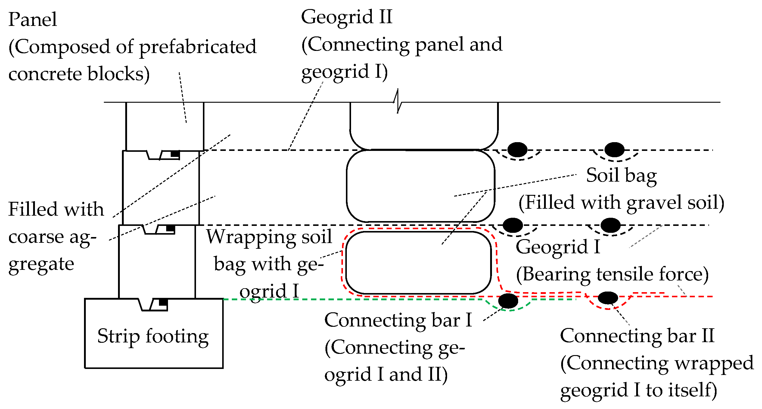
Figure 1 shows that the concrete-block-panel-wrapped RSW consists of precast concrete blocks forming the panel, with an internally WRSZ. Figure 2 shows details of the connection between the reinforcements and panel. The soil bags wrapped with reinforcements function as barriers that disrupt the transmission of cyclic loading-induced stresses and deformations, thereby reducing the horizontal stress acting on the panel and mitigating horizontal displacement of the panel. This mechanism not only enhances overall structural stability but also provides protection for the reinforcement-facing interface with modular panels. Given these engineering advantages, it is imperative to examine the mechanical behavior and stress evolution of this composite system under cyclic loading simulating long-term railway traffic. Such investigations are expected to clarify its long-term performance and offer critical technical references for implementing concrete-block-panel-wrapped RSWs in railway engineering applications.

2. Experimental Program

2.1. Materials

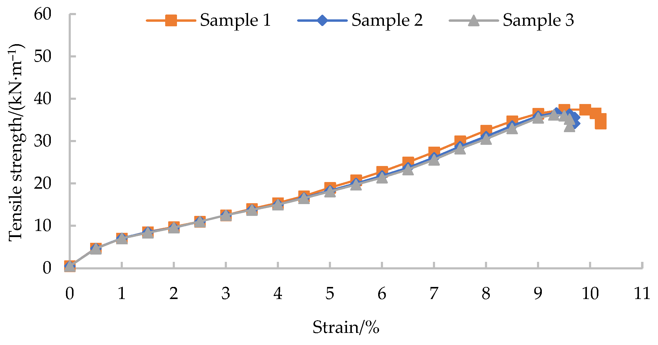
The RSW employed sand as backfill material and high-density polyethylene (HDPE) uniaxial geogrids as reinforcement. Table 1 and Table 2 summarize the key physical and mechanical properties of the backfill and reinforcement, obtained from physical property tests of soil and tensile test of reinforcement. The tensile stress–strain curve of reinforcement is shown in Figure 3.

2.2. Model Setup

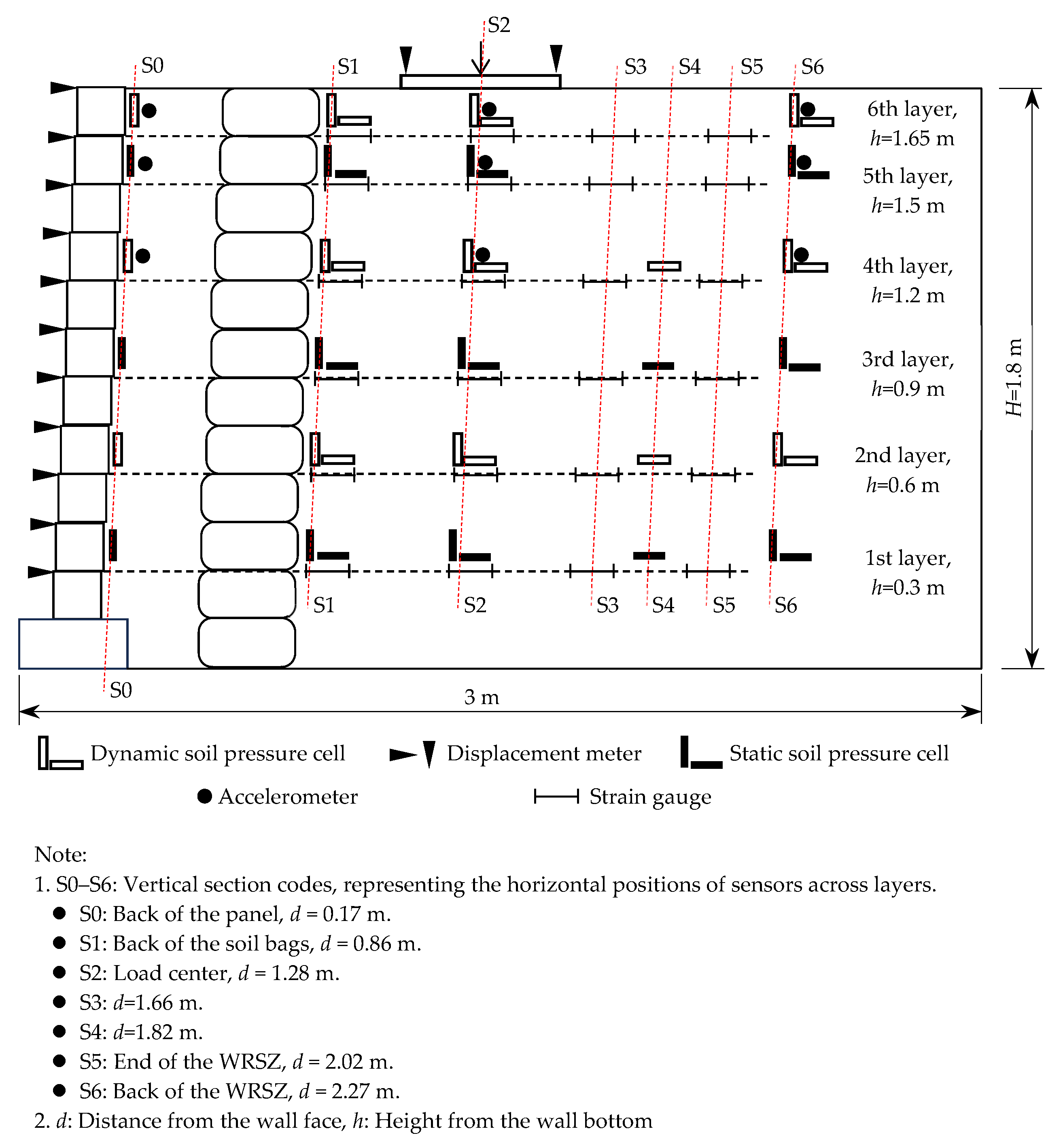
The model of the concrete-block-panel-wrapped RSW with a slope ratio of 1:0.05 measured 3.0 m in length, 1.0 m in width, and 1.8 m in height, incorporating six layers of geogrid. Each layer of geogrid was 2.0 m in length with a vertical spacing of 0.3 m or 0.15 m, as can be seen in Figure 4. Following compaction, the backfill attained a relative density exceeding 0.75.
To mitigate the influence of boundary effects, the following measures were implemented: (1) lubricant was applied to the inner surfaces of the model container sidewalls to reduce friction between the sidewalls and the soil; and (2) monitoring sensors were positioned along the central cross-section of the model width. The experimental data demonstrate that the measured dynamic response signals were clear and stable, exhibiting expected trends of mechanical behavior with the increase in the number of load cycles, which confirms that boundary effects were effectively controlled.

2.3. Monitoring Scheme

Under the cyclic axle loads of trains, after being transmitted and filtered through the track system, the dominant frequency components of the vibrational responses generated in subgrade are sinusoidal. Therefore, to simulate train-induced dynamic loading, the experimental setup applied sinusoidal cyclic loading. Due to the limitation of the maximum frequency (10 Hz) of cyclic loading that the equipment can apply, the frequency was set to 10 Hz, corresponding train speed is 198 km/h under the condition of a minimum wheelbase of 5.5 m. The number of load cycles was set to 1 million. The magnitude of the applied cyclic load was 60~120 kPa based on dynamic stress levels typically recorded at the surfaces of ballasted high-speed railway subgrades during train passage. The parameters monitored throughout the experiment included soil stress, horizontal displacement, vertical settlement, acceleration, and reinforcement strain. The sensor configuration employed to capture these measurements is illustrated in Figure 4.
This test employed a professional dynamic signal measurement system, with the core equipment consisting of:
  • Portable Signal Conditioner with Superior Anti-Electromagnetic Interference Capability: This device integrates key functions such as signal amplification, low-pass filtering, and pre-balancing, specifically designed to acquire high-quality weak strain/stress signals in complex electromagnetic environments.
  • 24-bit Network Dynamic Strain Acquisition System: Used for high-resolution data acquisition.
The sampling frequency for all dynamic sensors was set to 256 Hz. The signal conditioner features a built-in hardware low-pass filter, as an effective hardware anti-aliasing measure, fundamentally preventing high-frequency noise from aliasing into our frequency band of interest. Before data acquisition, the initial zero drift of the sensors was eliminated using the “pre-balancing” function of the signal conditioner. All sensors underwent rigorous calibration prior to testing. Their specific accuracies are listed in Table 3.

3. Results

3.1. Deformation

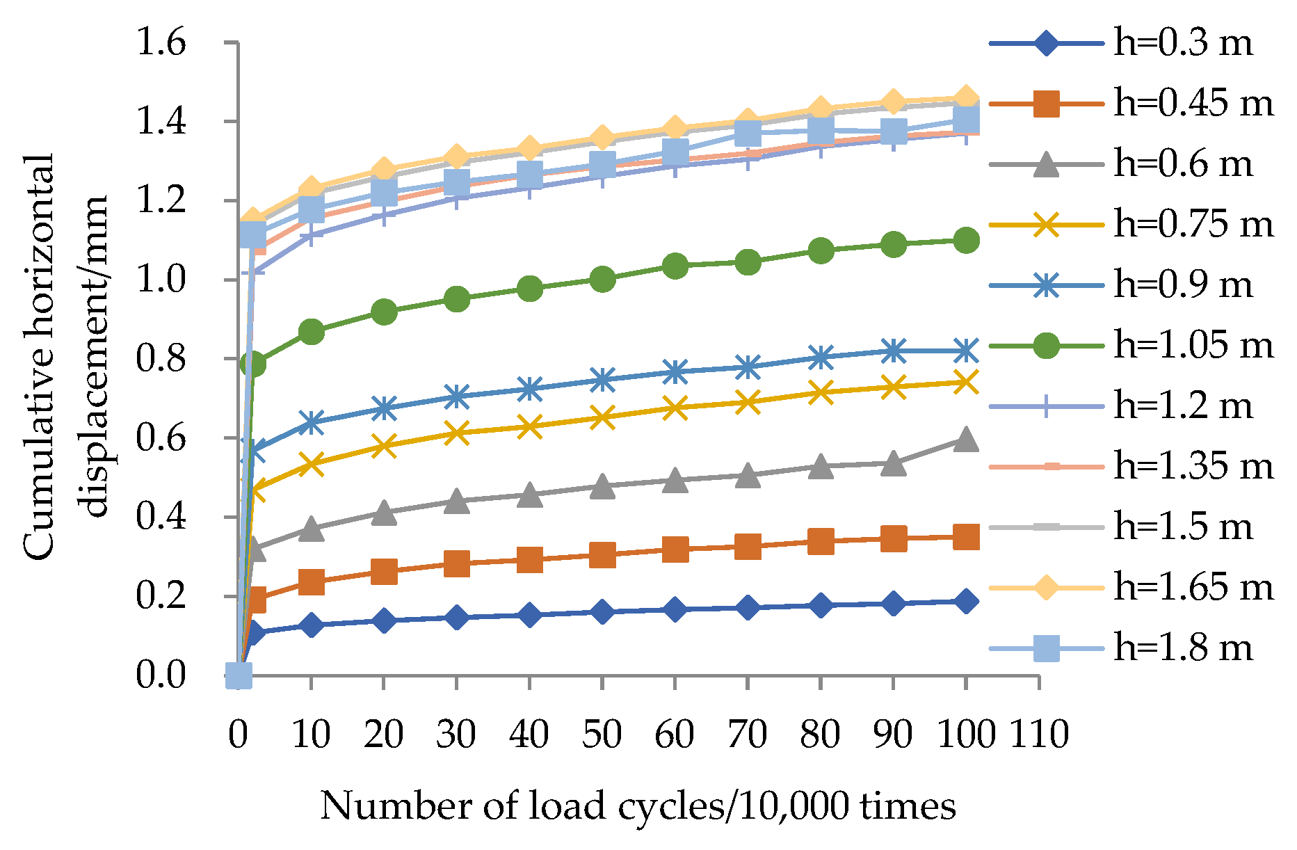
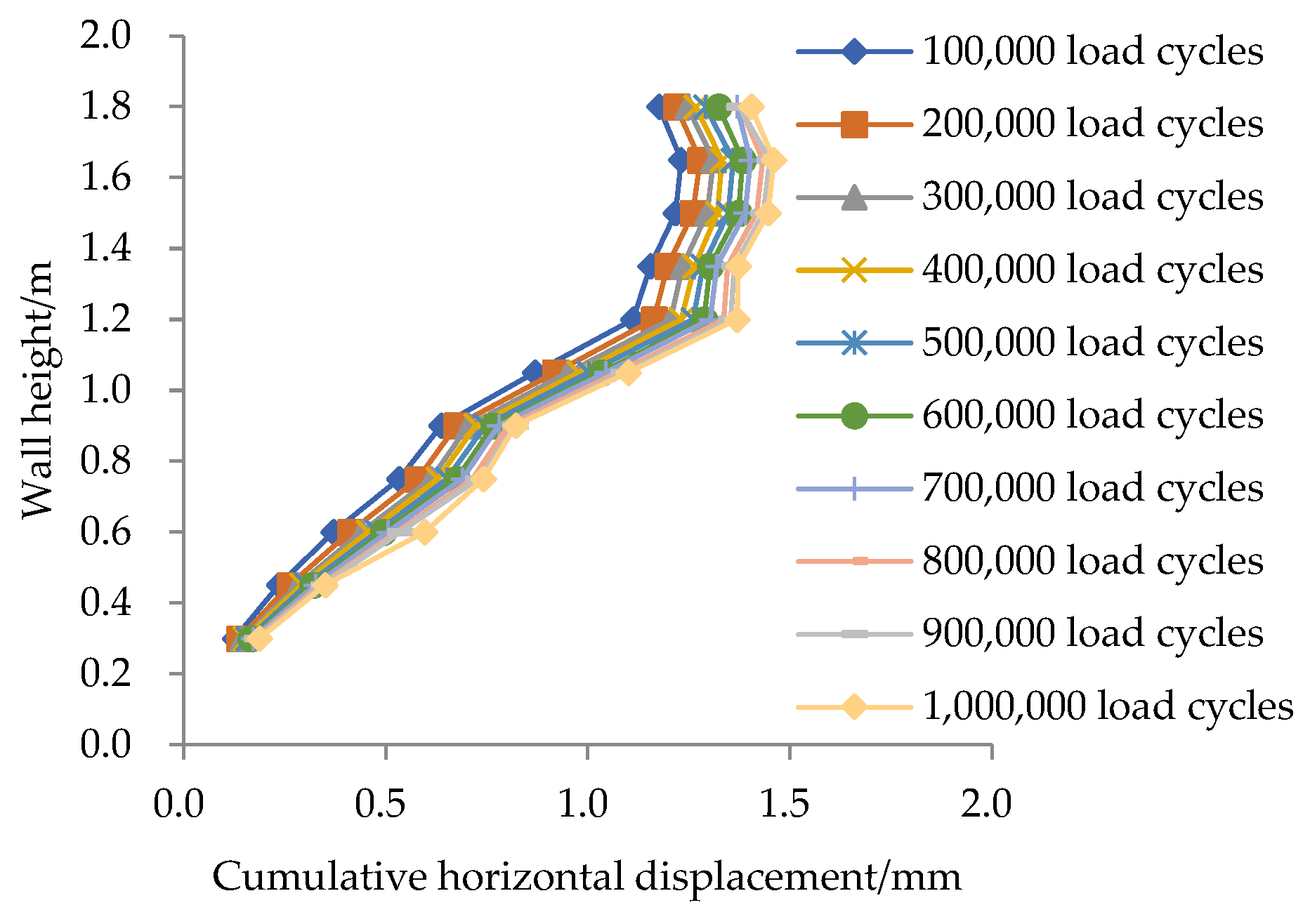
Figure 5 and Figure 6 show the variation and distribution of panel horizontal displacement as the number of load cycles increases. The results indicate that horizontal displacement increases progressively, eventually reaching a stable state, and its maximum value is 1.46 mm. This corresponds to 0.08%H.
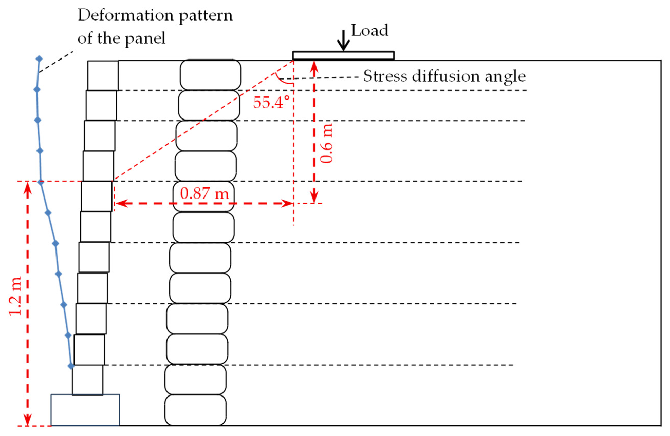
During the first 20,000 load cycles, horizontal displacement exhibits a pronounced increase as the number of load cycles increases. The displacement rises progressively from the base to higher sections along the height of the wall. Above 0.33H, the displacement shows minimal change, suggesting that the externally applied load primarily influences the lower 0.33H portion of the wall, estimating the stress diffusion angle of 55.4° by the deformation pattern of the panel, shown in Figure 7, which exceeds the 27° recommended by FHWA guidelines.
Following the first 20,000 load cycles, the rate of horizontal displacement significantly decreases, and the displacement becomes uniformly distributed along the height of the wall. This behavior verifies the effectiveness of the WRSZ in obstructing the transmission of soil deformation, thereby reducing and homogenizing panel deformation.
According to the mechanisms of stress diffusion and attenuation, the mid-lower region of the wall face undergoes more pronounced effects from external loading. For wrapped RSW systems characterized by wall faces with negligible flexural rigidity, the maximum horizontal displacement is observed in the mid-lower portion. In contrast, for concrete block panel RSW configurations, the interlocking nature of the panel modules promotes upward propagation of horizontal displacement along the wall face, forming a gradient that increases progressively from the base to the crest. The embedded sections of soil bags reinforced with wrapped geogrids effectively mitigate and equalize the horizontal deformation, thereby impeding the upward migration of displacement. This phenomenon accounts for the horizontal deformation pattern observed in Figure 6, wherein displacement in the upper wall regions remains relatively unchanged.
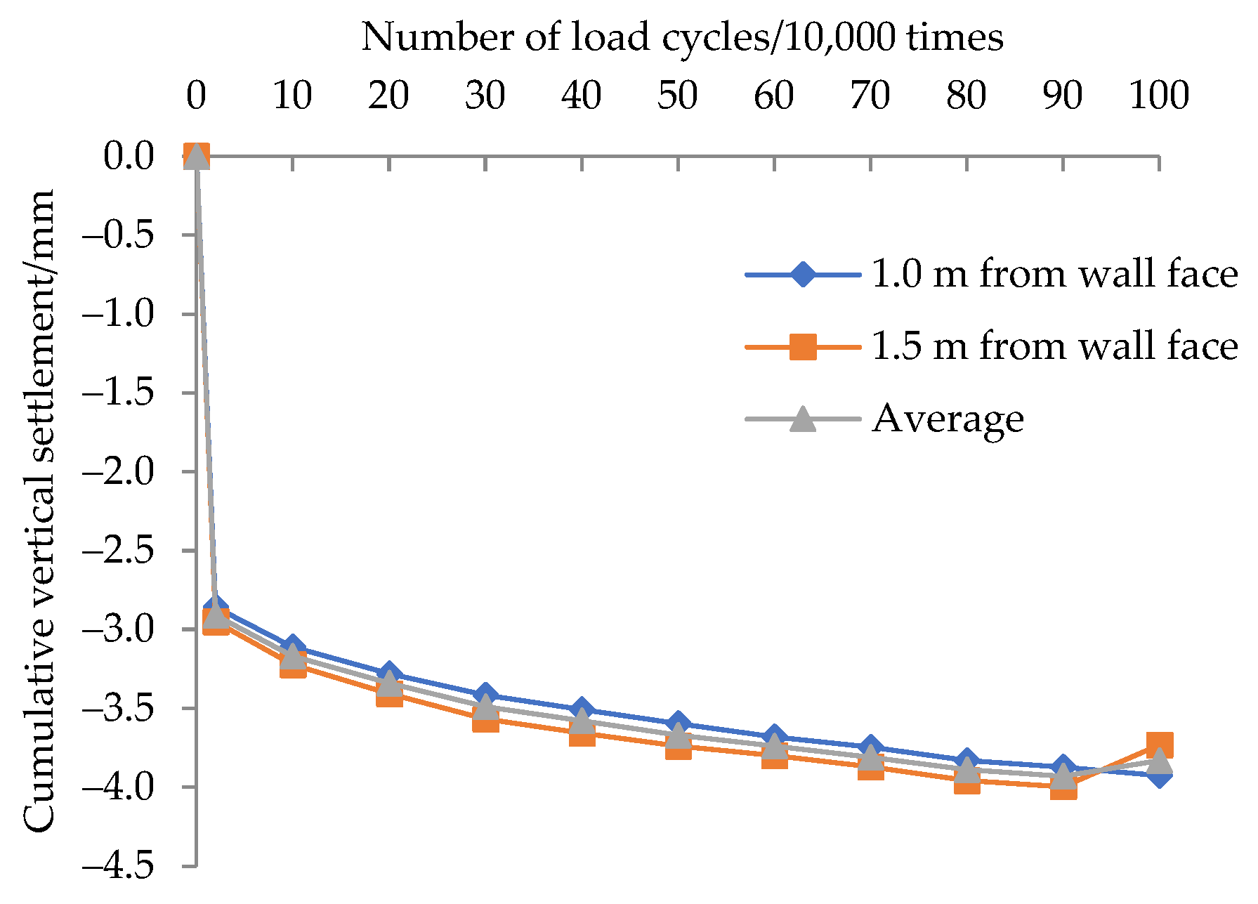
Figure 8 depicts the variation in cumulative vertical settlement at the wall crest, as the number of load cycles increases. As shown, the settlement gradually increases with load cycles and eventually stabilizes, reaching a final average settlement of 3.83 mm, equivalent to 0.21%H. This trend mirrors the behavior observed in horizontal displacement, wherein settlement is most pronounced during the first 20,000 load cycles and then the increase in settlement is very small, contributing only 0.92 mm or 24.02% of the total settlement. Under experimental conditions (without foundation effects), the settlement primarily comprises two components:
  • Settlement induced by one dimensional compression of the reinforced soil;
  • Settlement induced by horizontal displacement of the wall.

3.2. Vertical Acceleration

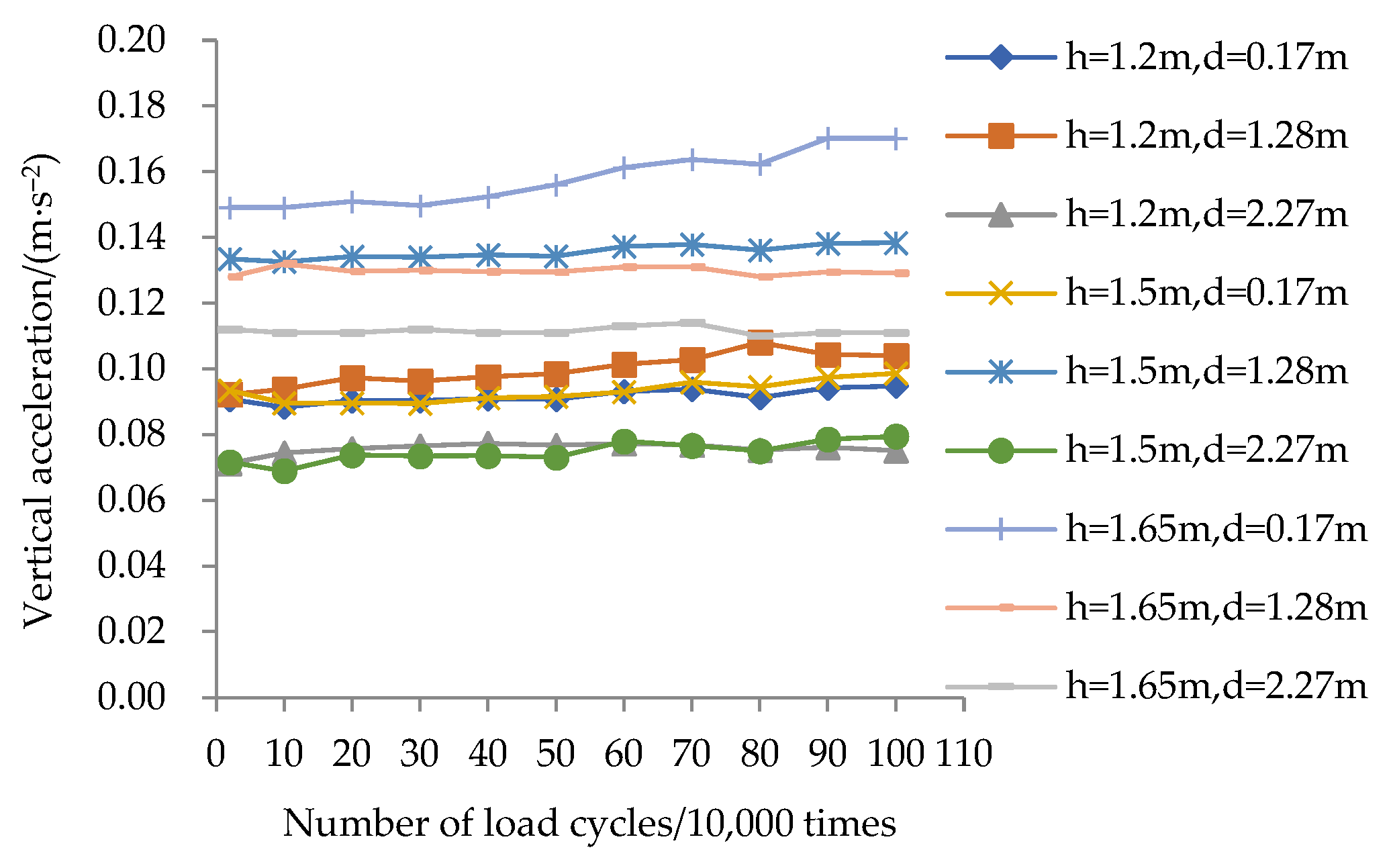
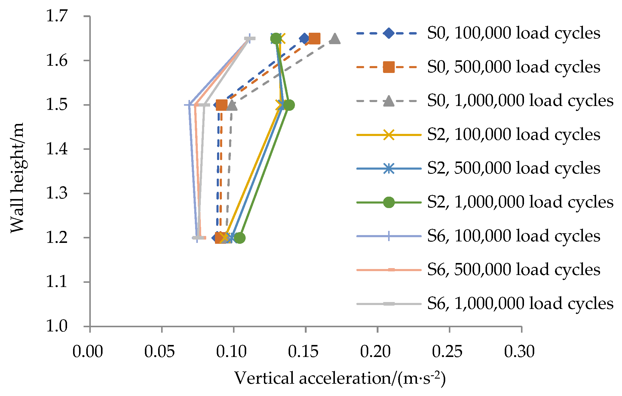
Figure 9 illustrates the variation in vertical acceleration with the increasing number of load cycles at different heights and distances from the wall face within the RSW, while Figure 10 presents the variation in vertical acceleration with the depth at different vertical sections and number of load cycles. The results indicate that, owing to the high stiffness of the reinforced soil, acceleration increments remain minimal throughout the test, with a maximum increase of 0.02 m/s2.
Along the height of the wall, the acceleration attenuation varies spatially at different vertical sections:
  • Attenuation is slower at the load center section (S2).
  • Attenuation is more rapid in regions located farther from the load center, particularly near the back of the panel (S0) and the rear of the WRSZ (S6).
After attenuation from the top to a depth of 0.6 m:
  • Accelerations within the WRSZ (S0 and S2) converge to 0.09–0.10 m/s2.
  • Accelerations in the non-WRSZ (S6) are lower, ranging from 0.074 to 0.077 m/s2, thereby confirming the enhanced stiffness provided by the reinforced soil.

3.3. Soil Stress

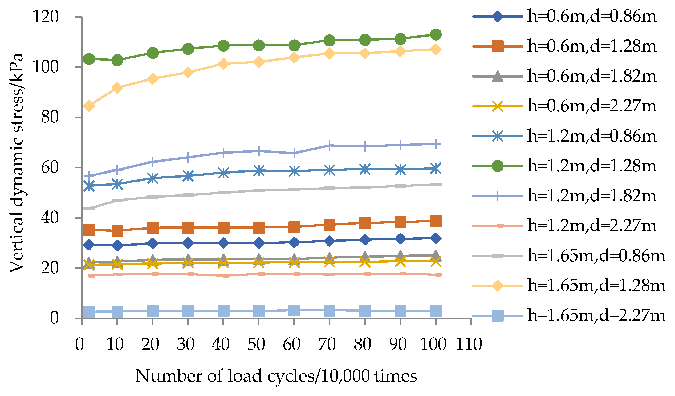
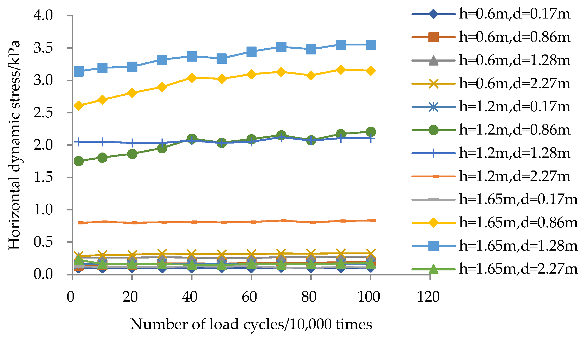
Figure 11 and Figure 12 display the variations in vertical and horizontal dynamic stresses within the retaining wall under increasing load cycles. Both vertical and horizontal dynamic stresses are observed to increase progressively with load cycles and stabilize over time. Due to the diffusion and attenuation of external load-induced stresses in the soil, stress increments are more pronounced near the loading position, with the maximum increment occurring directly beneath the load. Along the horizontal direction, both vertical and horizontal dynamic stresses exhibit nonlinear distributions, peaking beneath the loading position and gradually decreasing toward both reinforcement ends. This pattern reflects the localized stress concentration at the load source and its subsequent radial dissipation through the reinforced soil mass.
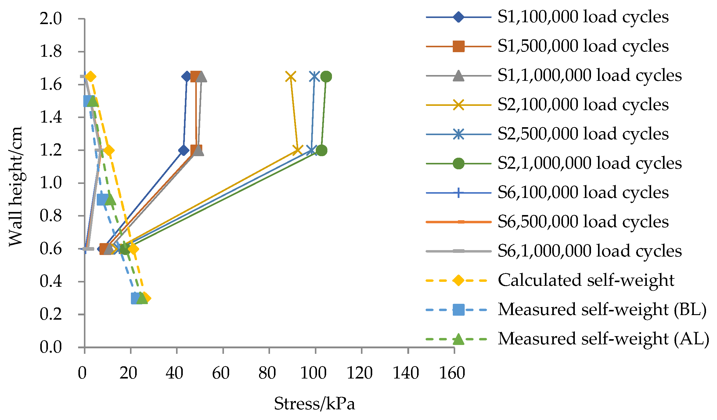
The variation in vertical dynamic stress along the height of the wall at sections situated at different distances from the panel under cyclic loading is presented in Figure 13. Comparisons between calculated and measured self-weight stresses are also included. The following key observations can be made:
  • At sections near the loading position (S1 and S2), the vertical dynamic stress remains nearly constant in the upper wall (higher elevation) and gradually attenuates with depth in the mid-lower wall (lower elevation).
  • At the section located farther from the loading position (S6), the vertical dynamic stress follows a non-monotonic trend, initially increasing and subsequently decreasing with depth.
This distribution pattern aligns with the Boussinesq analytical solution for additional stress distribution induced by localized vertical uniform loads on foundation soils, despite the presence of a free face in the RSW. This observation suggests that the stress state within the RSW approximates a confined stress condition similar to that of a foundation and remains within the elastic regime, thereby validating the high stiffness and low deformability of the RSW.
Near the loading position (S1 and S2), vertical dynamic stresses begin to attenuate at h = 1.2 m (0.67H) and diminish to zero at h = 0.5 m (0.28H). During the loading process, the measured self-weight stress consistently remains lower than the value calculated based on the maximum dry density but gradually increases and approaches theoretical values.
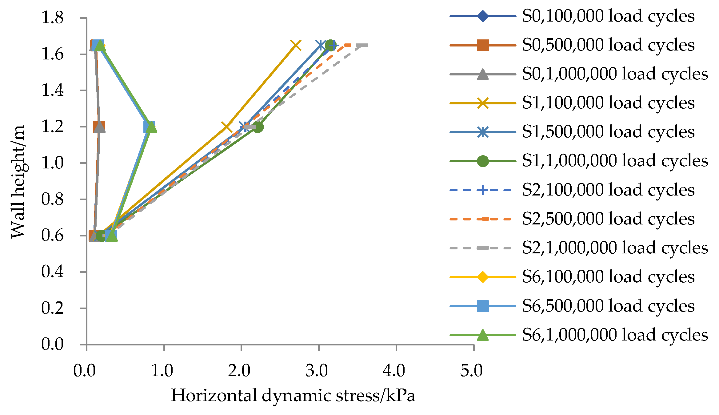
The variation in horizontal dynamic stress along the height of the wall at sections positioned at varying distances from the wall face is illustrated in Figure 14. The key findings are as follows:
  • Near the loading position (S1 and S2), horizontal dynamic stress decreases progressively from higher to lower elevations due to stress diffusion.
  • At locations farther from the load (S0 and S6), horizontal dynamic stress initially increases and then decreases along the height of the wall.
  • At the back of the panel (S0), horizontal dynamic stress remains minimal and is uniformly distributed across the wall height.
This behavior indicates that the internal wrapped structure effectively impedes stress transmission through the soil mass, thereby reducing and homogenizing horizontal dynamic stress on the panel.

3.4. Geogrid Strain

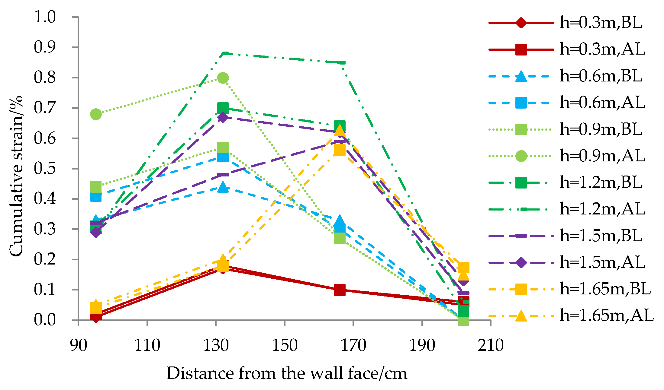
Figure 15 illustrates the variation in cumulative geogrid strain before and after cyclic loading. Along the length of the reinforcement, the geogrid strain has only one maximum value, with relatively greater variation occurring near the back of the soil bags. The analysis attributes the formation of the peak to the presence of a potential sliding surface, while the elevated strain near the rear of the soil bags results from differential settlement between the graded gravel within the bags and the surrounding backfill.
As the number of load cycles increases, the strain increment observed by the end of loading remains minimal (maximum: 0.23%), indicating that cyclic loading exerts negligible influence on the strain. The primary growth in strain occurs during the compaction stage of construction, which improves the friction effect between the soil and reinforcements. The geogrid strain is small at its end, suggesting a limited reinforcing effect. This condition facilitates a smooth transition between reinforced and unreinforced zones, thereby preventing abrupt stiffness changes or substantial differential settlement.
The maximum observed strain (0.88%) occurs at h = 1.2 m (0.67H). As the burial depth of the geogrid increases, the strain of the geogrid first increases and then decreases. This behavior is attributed to the significant stress developing near the mid-height of the wall due to stress diffusion. The maximum tensile stress in the geogrid reaches 7.48 kN/m, corresponding to 20.33% of its ultimate tensile strength.
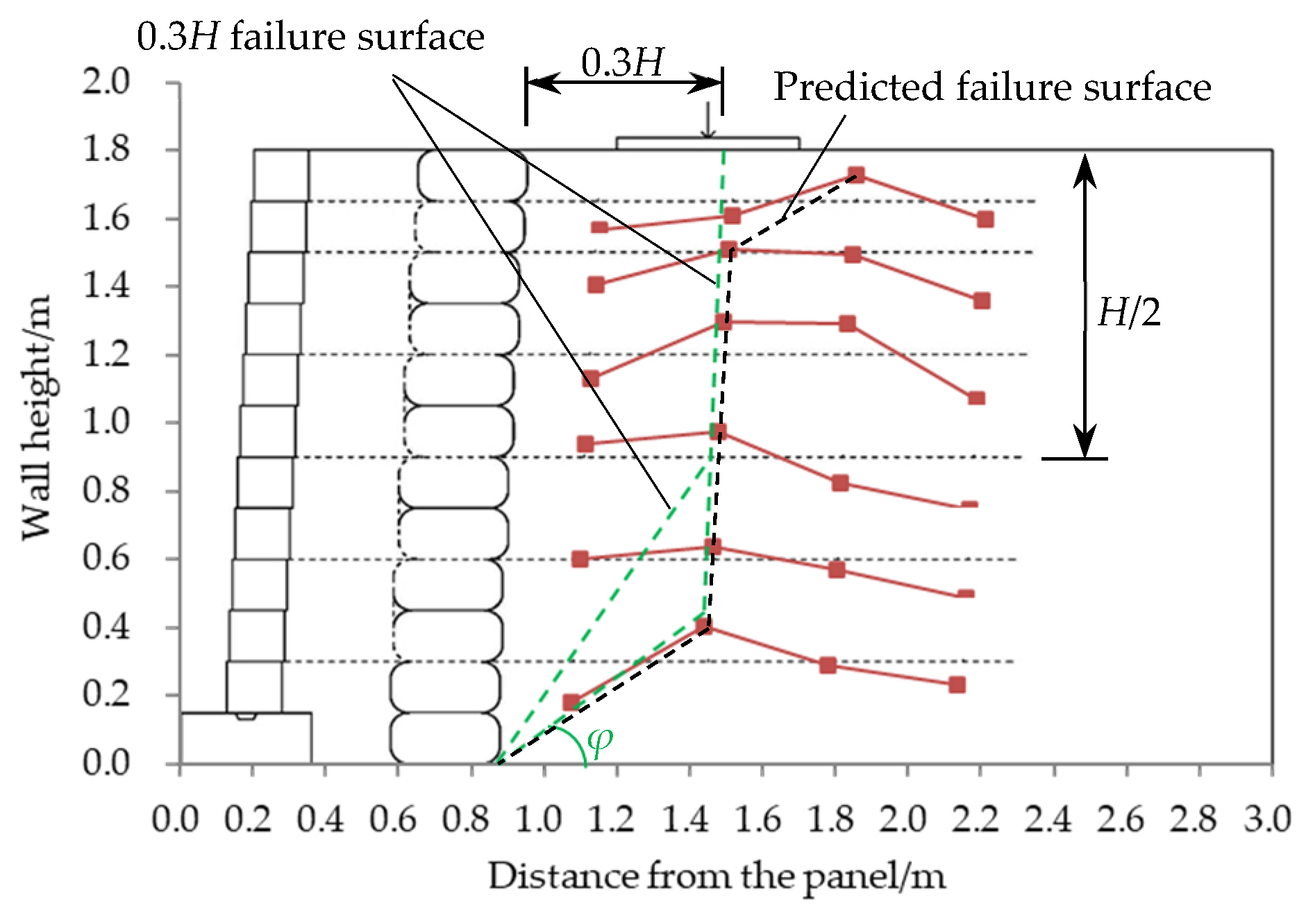
Figure 16 aggregates the cumulative strain distribution curves of geogrids to predict the failure surface location. Observations reveal that the peak strain positions in each layer progressively shift away from the wall face with increasing elevation. Based on this pattern, the predicted failure surface approximates a bilinear configuration:
  • There is a line parallel to the panel, situated at a distance of 0.3H from the back of the soil bags.
  • A second line inclined at an angle equal to the internal friction angle (φ) of the soil relative to the horizontal plane.
This configuration deviates from the “0.3H failure surface” recommended by the FHWA for conventional RSWs. The observed behavior highlights two principal mechanisms:
  • Stress and deformation control: The wrapped structure effectively blocks and homogenizes stress transmission, thereby mitigating strain localization.
  • Anti-sliding stability: By intercepting the potential sliding surface passing through the base of the wall, the wrapped system enhances resistance against sliding.

4. Discussion

This model test demonstrates that the internal wrapped structure significantly enhances the mechanical performance of RSW. Specifically, the internal wrapped structure effectively homogenizes the horizontal dynamic stress acting on the panel, obstructs the transmission of deformation, and intercepts the potential failure surface passing through the wall base, thereby markedly improving anti-sliding stability. These observations align well with the fundamental principles of reinforced soil structures.
Regarding the design parameters, the reinforcement length-to-wall height ratio (L/H) adopted in this study was 1.11. This relatively high ratio is fully consistent with the concept emphasized in the FHWA design guidelines that sufficient reinforcement length is crucial for ensuring internal stability and controlling deformations. The minimal wall displacements observed in the test confirm that this ratio adequately meets the stringent requirements for subgrade retaining structures in high-speed railways under the service limit state.
It is particularly noteworthy that the inclusion of the wrapped structure alters the traditional load-bearing mechanism. The test revealed that after installing the internal wrapped structure, the lateral earth pressure acting on the panel is not only effectively blocked but also redistributed and homogenized. This mechanism directly yields three key benefits: first, it provides additional lateral confinement, improving the stress state near the panel; second, it effectively reduces stress concentration, optimizing the deformation mode of the structure; and finally, it mitigates the dynamic stresses transmitted to the connection between the panel and the reinforcements.
These findings hold significant implications for engineering practice. For RSWs with concrete block panels, which offer advantages such as simple and rapid construction, the lateral earth pressure directly acting on the panel in traditional configurations can easily lead to substantial local deformation. This study shows that after implementing the internal wrapped structure, structural deformation is significantly reduced, and stability is markedly improved. This provides strong support for the application of this structural form in engineering projects with strict deformation requirements, such as high-speed railways. Furthermore, this improvement offers new insights for connection design and panel stress verification. It is recommended that future designs consider the beneficial effects of the internal wrapped structure, with reference to the relevant requirements in the FHWA guidelines.
This large scale model test has both advantages and disadvantages. The large-scale physical model enables direct observation of complex mechanical behavior under well-controlled cyclic loading conditions that would be difficult to achieve in field tests. The experimental setup incorporated high-precision sensors with appropriate sampling rates and filtering techniques, ensuring reliable capture of dynamic responses. However, While being a large-scale test, complete simulation of all field conditions cannot be achieved. This study focused on one specific RSW configuration, additional geometries and reinforcement arrangements would provide more comprehensive insights.
In the next step of research, the dynamic properties of materials will be further measured, and then conduct the numerical simulation analysis of the mechanical behavior of concrete-block-panel-wrapped RSW, aiming at:
  • Reveal the influence of key parameters on concrete-block-panel-wrapped RSW.
  • Quantify the stress diffusion angle from computed stress contours precisely.

5. Conclusions

As the model test results show, the concrete-block-panel-wrapped RSW demonstrates satisfactory stability under long-term cyclic loading at the wall crest. The following key conclusions have been drawn:
  • The horizontal deformation of the panel increases with an increasing number of load cycles and eventually stabilizes, reaching a maximum value of 0.08%H. The deformation progressively increases from the base of the panel to its top. After 20,000 load cycles, deformation growth becomes minimal and relatively uniform along the height of the wall, indicating a stress diffusion angle of 55.4°.
  • The maximum average settlement stabilizes at 0.21%H. A significant portion of the total settlement occurs within the first 20,000 load cycles. Beyond this point, settlement increments become negligible, accounting for only 24.02% of the total settlement.
  • The vertical acceleration increases marginally with an increasing number of load cycles, with a maximum increment of 0.02 m/s2. The attenuation of the vertical acceleration is slower at the section corresponding to the load center, while it proceeds more rapidly at the sections located behind both the panel and the WRSZ. Through these differing attenuation processes, accelerations within the reinforced zone converge and remain lower than those in the non-reinforced zone.
  • Both vertical and horizontal dynamic stresses increase and subsequently stabilize with continued cyclic loading. The decay pattern of vertical dynamic stress aligns with Boussinesq analytical solutions for foundation soils, confirming elastic behavior. The vertical and horizontal dynamic stresses gradually decrease on the vertical sections within the range of load application, and they show a trend of first increasing and then decreasing on the vertical sections outside the range of load application. The horizontal dynamic stress acting on the back of the panel remains low and uniformly distributed. Measured self-weight stress increases during loading but remains below analytically calculated values.
  • The cumulative strain of the geogrid exhibits a single-peak distribution along the reinforcement length, with a maximum value of 0.88%, corresponding to maximum tensile stress reaching 20.33% of the geogrid’s ultimate tensile strength. The predicted failure surface approximates a bilinear configuration, comprising a line parallel to the wall face located 0.3H behind the soil bags and a second line inclined at an angle equal to the soil’s internal friction angle (φ) relative to the horizontal plane.

Author Contributions

Writing—original draft preparation, J.X.; investigation, X.Z.; data curation, Z.S.; funding acquisition, H.W.; conceptualization, H.W. All authors have read and agreed to the published version of the manuscript.

Funding

This research was funded by the National Key Research and Development Program of China, grant number 2022YFE0104600, and the National Natural Science Foundation of China, grant number 52079078.

Data Availability Statement

The data used to support the findings of this study are available from the corresponding author upon request.

Conflicts of Interest

Authors Jiannan Xu and Xiancai Zhou were employed by the company China Railway Engineering Design and Consulting Group Co., Ltd. The remaining authors declare that the research was conducted in the absence of any commercial or financial relationships that could be construed as a potential conflict of interest.

Abbreviations

The following abbreviations are used in this manuscript:
RSWReinforced soil retaining wall
WRSZWrapped reinforced soil zone
HDPEHigh-density polyethylene
BLBefore loading
ALAfter loading

References

  1. Aalami, M.R.; Anari, A.; Shafighfard, T.; Talatahari, S. A robust finite element analysis of the rail-wheel rolling contact. Adv. Mech. Eng. 2013, 5, 272350. [Google Scholar] [CrossRef]
  2. Augusto, M.; Felipe, L.; Federico, F. Mechanically Stabilized Earth (MSE) retaining wall at hotel in Bariloche City. E3S Web Conf. 2024, 569, 23004. [Google Scholar] [CrossRef]
  3. Cai, F. Finite element modeling of mechanical behavior of geogrid reinforced soil retaining walls. Proc. Indian Natl. Sci. Acad. 2025, 91, 484–497. [Google Scholar] [CrossRef]
  4. Kilic, I.E.; Cengiz, C.; Edincliler, A.; Guler, E. Seismic behavior of geosynthetic-reinforced retaining walls backfilled with cohesive soil. Geotext. Geomembr. 2021, 49, 1256–1269. [Google Scholar] [CrossRef]
  5. Li, S.H.; Cai, X.G.; Xu, H.L.; Jing, L.P.; Huang, X.; Zhu, C. Dynamic behaviour of reinforced soil retaining wall under horizontal seismic loading. IOP Conf. Ser. Earth Environ. Sci. 2020, 569, 012001. [Google Scholar] [CrossRef]
  6. Xu, P.; Hatami, K.; Jiang, G.L. Shaking table performance of reinforced soil retaining walls with different facing configurations. Geotext. Geomembr. 2021, 49, 516–527. [Google Scholar] [CrossRef]
  7. Hossain, M.Z.; Hore, R.; Ansary, M.A. Model tests of reinforced soil retaining sand walls by shaking table test. Arab. J. Geosci. 2024, 17, 166. [Google Scholar] [CrossRef]
  8. Cai, B.Y.; Cai, X.G.; Li, S.H.; Huang, X.; Zhang, Y.; Xiao, C.Z. Experimental study of shaking table for reinforced soil retaining walls: Analysis of tiered configuration effects. Soil Dyn. Earthq. Eng. 2025, 188 Pt B, 109076. [Google Scholar] [CrossRef]
  9. Xu, L.; Ling, H.I. Centrifuge modeling and numerical analysis of reinforced soil retaining walls with concrete block facing. Transp. Infrastruct. Geotechnol. 2020, 7, 405–425. [Google Scholar] [CrossRef]
  10. Mirmoradi, S.H.; Ehrlich, M. Effect of facing stiffness on reinforced soil walls under surcharge loading-unloading. Int. J. Phys. Model. Geotech. 2025, 25, 2–16. [Google Scholar] [CrossRef]
  11. Zhang, W.; Chen, J.F. Numerical modeling of geosynthetic reinforced soil retaining walls with different toe restraint conditions. Geotext. Geomembr. 2023, 51, 16–29. [Google Scholar] [CrossRef]
  12. Kim, Y.J.; Jung, H.S.; Lee, Y.J.; Oh, D.W.; Son, M.; Yoon, H.H. Behaviour analysis of reinforced soil retaining wall according to laboratory scale test. Appl. Sci. 2020, 10, 901. [Google Scholar] [CrossRef]
  13. Zhu, Y.L.; Zhan, Z.J.; Hong, Y.; Guo, P.P.; He, M.; Chen, R.Y. Experimental study on mechanical and deformation characteristics of geogrid-reinforced soil retaining walls. Int. J. Geosynth. Ground Eng. 2024, 10, 74. [Google Scholar] [CrossRef]
  14. Bhattacharjee, A.; Amin, M.U. Behaviour of Two-Tiered Geosynthetic-Reinforced Soil Walls. INAE Lett. 2019, 4, 91–100. [Google Scholar] [CrossRef]
  15. Gao, S.; Xiao, C.Z.; Han, J.; Wang, Z.H. Lateral displacements of geosynthetic-reinforced soil walls in a tiered configuration. J. Geotech. Geoenviron. Eng. 2022, 148, 04022066. [Google Scholar] [CrossRef]
  16. Hulagabali, A.M.; Solanki, C.H.; Dodagoudar, G.R.; Anitha, N. Finite Element Analysis of Segmental Precast Concrete Panel Reinforced Earth Retaining Wall. Jordan J. Civ. Eng. 2023, 17, 582–597. [Google Scholar] [CrossRef]
  17. Hulagabali, A.M.; Solanki, C.H.; Dodagoudar, G.R.; Anitha, N. Seismic Internal Stability Analysis of Modular Block Reinforced Earth Retaining Wall. Int. J. Geosynth. Ground Eng. 2023, 9, 31. [Google Scholar] [CrossRef]
  18. Liu, H.B.; Wang, C.H.; Wang, L. Analyzing operational reinforcement loads of geosynthetic-reinforced soil retaining walls based on plasticity theory. Zhongguo Kexue Jishu Kexue/Sci. Sin. Technol. 2022, 52, 1083–1095. [Google Scholar] [CrossRef]
  19. Lu, L.; Chen, B.; Liu, P.; Wang, Z.J.; Arai, K. Seismic time-history analysis of block-faced reinforced-soil retaining wall based on pseudo-dynamic method. Geotext. Geomembr. 2024, 52, 494–510. [Google Scholar] [CrossRef]
  20. Ren, F.F.; Huang, Q.Q.; Zhang, F.; Wang, G. Numerical study on seismic performance of tiered reinforced soil retaining walls. Soil Dyn. Earthq. Eng. 2024, 181, 108672. [Google Scholar] [CrossRef]
  21. Hore, R.; Chakraborty, S.; Shuvon, A.M.; Bari, M.F.; Ansary, M.A. Dynamic response of reinforced soil retaining wall resting on soft clay. Transp. Infrastruct. Geotechnol. 2021, 8, 607–628. [Google Scholar] [CrossRef]
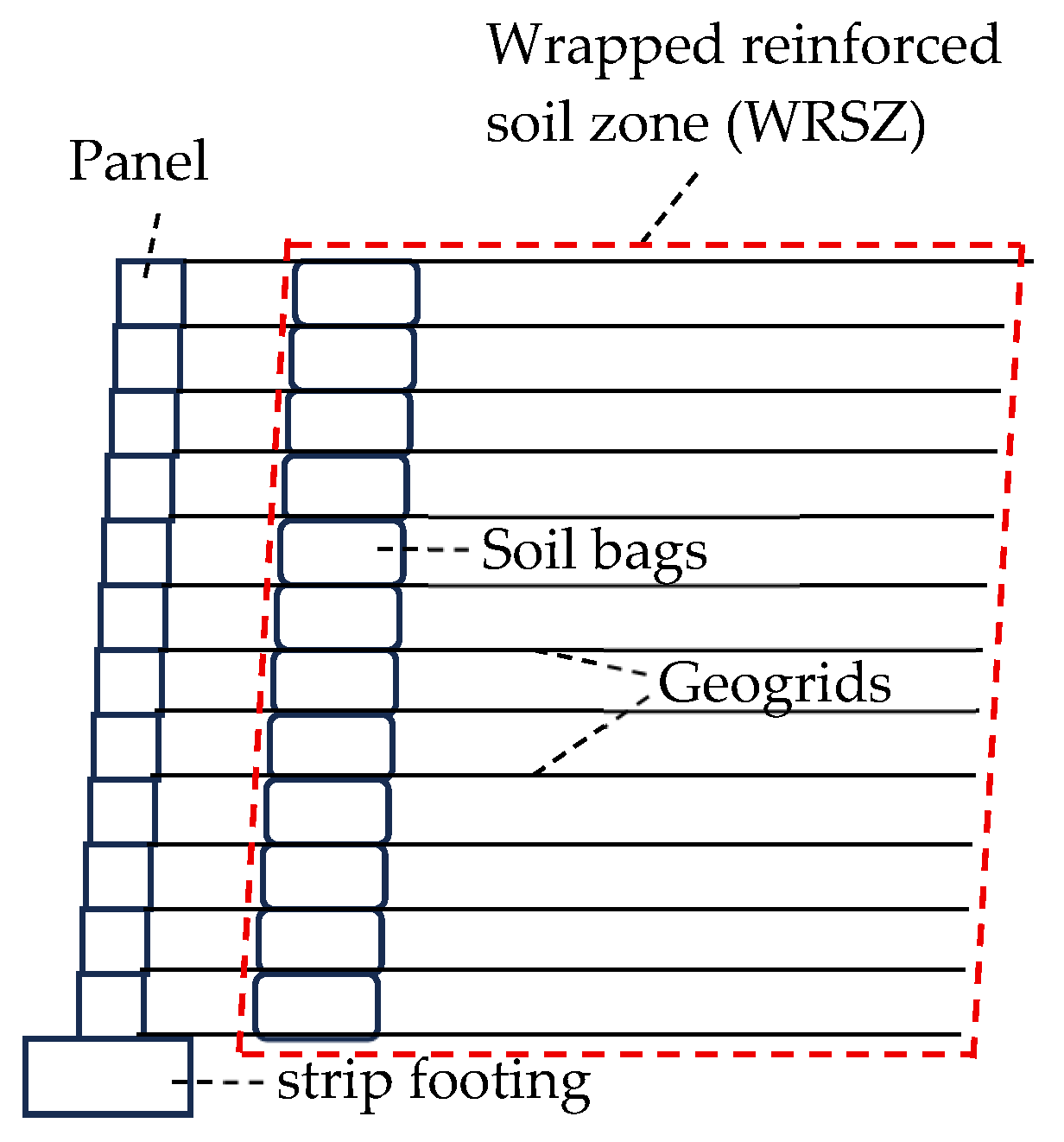
Figure 1. Structure of concrete-block-panel-wrapped RSW.
Buildings 15 03797 g001
Figure 2. Connection between reinforcements and panel.
Buildings 15 03797 g002
Figure 3. Tensile stress–strain curve of reinforcement.
Buildings 15 03797 g003
Figure 4. Sensor layout.
Buildings 15 03797 g004
Figure 5. Variation in panel horizontal displacement with increasing number of load cycles.
Buildings 15 03797 g005
Figure 6. Distribution of panel horizontal displacement along the height.
Buildings 15 03797 g006
Figure 7. Stress diffusion angle estimated by deformation pattern of the panel.
Buildings 15 03797 g007
Figure 8. Variation in cumulative vertical settlement of wall top with increasing number of load cycles.
Buildings 15 03797 g008
Figure 9. Variation in vertical acceleration with increasing number of load cycles.
Buildings 15 03797 g009
Figure 10. Distribution of vertical acceleration along the wall height.
Buildings 15 03797 g010
Figure 11. Variation in vertical dynamic stress with increasing number of load cycles.
Buildings 15 03797 g011
Figure 12. Variation in horizontal dynamic stress with increasing number of load cycles.
Buildings 15 03797 g012
Figure 13. Distribution of vertical dynamic stress and self-weight stress along the wall height. Note: 1. Solid line: curves of vertical dynamic stress distributions. Dashed line: curves of self-weight stress distributions; 2. BL: before loading, AL: after loading.
Buildings 15 03797 g013
Figure 14. Distribution of horizontal dynamic stress along the wall height.
Buildings 15 03797 g014
Figure 15. Variation in cumulative geogrid strain. Note: BL: before loading, AL: after loading.
Buildings 15 03797 g015
Figure 16. Prediction of RSW failure surface.
Buildings 15 03797 g016
Table 1. Key physical property parameters of backfill materials.
ParameterValue
Internal friction angle/(°)36.6
Maximum dry density/(g·cm−3)1.76
Water Content/%0
Table 2. Key mechanical property parameters of reinforcement.
ParameterValue
Tensile strength/(kN·m−1)36.79
Tensile strength at 2% strain/(kN·m−1)9.45
Tensile strength at 5% strain/(kN·m−1)17.74
Maximum strain/%9.8
Table 3. The accuracies of sensors.
SensorRangeAccuracy
Dynamic soil pressure cell0.3 MPa1‰ FS (Full Scale)
Displacement meter50 mm0.01 mm
Static soil pressure cell0.3 MPa0.1% FS
Accelerometer±2 g0.1% FS
Strain gauge50 mm0.5% FS
Disclaimer/Publisher’s Note: The statements, opinions and data contained in all publications are solely those of the individual author(s) and contributor(s) and not of MDPI and/or the editor(s). MDPI and/or the editor(s) disclaim responsibility for any injury to people or property resulting from any ideas, methods, instructions or products referred to in the content.