1. Introduction
Permafrost is ground (soil or rock, including ice) with a temperature at or below 0 °C for at least two consecutive years [
1,
2], which is a product of heat and mass exchange within the lithosphere-soil-atmosphere system [
3]. Modern permafrost covers approximately 25% of the land area in the Northern Hemisphere (
Figure 1) and is mainly distributed in high-latitude regions and high-altitude areas. Among these, high-latitude permafrost regions are primarily concentrated in various parts of the Arctic. The Arctic usually refers to the area within and around the Arctic Circle, and its geopolitical and energy values have attracted great attention from countries around the world [
4,
5]. To exploit abundant energy and mineral resources and promote social and economic development, a series of highways with asphalt pavements has been constructed in the Arctic permafrost regions. Due to the presence of ice, permafrost is highly sensitive to temperature changes [
1,
6,
7].
Under the scenario of global climate warming, the permafrost underlying highway projects in the Arctic regions has degraded severely [
8,
9,
10,
11,
12], leading to serious thaw settlement issues and putting the infrastructures constructed in the Arctic at risk [
13,
14]. Scientists and engineers had proposed many control measures to mitigate the permafrost degradation and the thaw-related problems occurred in embankments, such as crushed rock/air convection embankments [
10,
15,
16,
17,
18,
19], Air duct embankment [
20,
21], thermosyphon embankments [
22,
23], heat drain embankments [
24], reflective coatings embankments [
25,
26], sun/snow shed embankments [
27,
28] and composite embankments [
22].
In fact, the degradation/thaw of the permafrost beneath the embankments is attributed to the disturbance of the original surface energy balance and the permafrost thermal regime. Many factors (such as atmospheric radiation, wind convection, heat conduction, structure design parameter, embankment materials, snow and water ponding, and infiltration) [
29,
30,
31,
32] directly impacted the surface energy balance of the embankment and its supporting ground [
28]. They thus increased the temperature of the permafrost underlying the embankments. Of these, the solar radiation and snow accumulation are two typical factors directly impacting thermal regimes of the permafrost beneath embankments in the Arctic, which cannot be ignored. In the Arctic region, a large number of highways with different types of pavements (such as gravel, concrete, and asphalt concrete) have been constructed to promote regional economic development. Asphalt concrete pavements, which are smooth, low-dust, and durable, are not only widely used in urban areas but also find a certain degree of application in the Arctic region. Typically, Profiriev et al. (2019) pointed out that the northern regions of Russia have 88,000 km of motor vehicle lanes, among which highways with hard pavements (asphalt, cohesive soil) account for 67% of the total mileage: in Yamalo-Nenets and Khanty-Mansi AOs, over 90% of highway projects have been asphalt-paved; in the Krasnoyarsk Krai, asphalt concrete roads also account for a certain proportion (no more than 30%) [
33]. Public information shows that there are 3400 miles of roads in the Northern Regions (where permafrost is widely developed) of Alaska, 56% of which have been paved [
34]. Additionally, asphalt pavements are used in embankments in Canadian permafrost regions [
35]. In the Arctic region, there is a phenomenon of polar day in summer, with strong solar radiation. Due to its black surface and its low reflectance (0.1), the subgrade of asphalt pavement will absorb more solar radiation [
36], which will inevitably cause the temperature of the highway subgrade to rise, leading to the degradation of the underlying permafrost and resulting in the subgrade suffering from thaw settlement diseases. In addition, snow cover is an important component of the cryosphere in the Arctic region [
37,
38]. In the winter, the snow will accumulate on the slopes on both sides of the embankments. When the snow accumulates to a certain thickness, it shows a significant insulation effect and increases the temperature of the permafrost.
To reduce thermal disturbance by the solar radiation and snow cover, some control measures have been implemented. To reduce solar radiation absorption by asphalt pavements, some scholars proposed a type of asphalt pavement painted by white reflective coating to reduce solar radiation absorption as early as the 1980s and 1990s [
39,
40]. Reckard et al. (1985) verified the effectiveness of the white NIR reflective coating for highway thaw settlement control and found that the higher albedo of the white NIR reflective coating led to significantly less thaw settlement in all sections compared to the unpainted controls [
41]. Richard et al. (2015) summarised and documented the field tests evaluating the cooling performance of reflective coating with various colours in different sites (campus of Laval University, Alaska Highway, and Tasiujaq) [
42]. Testing results showed that the surface temperature and n-factor decreased with increasing albedo. For example, based on a one-month monitoring period, for the reflective coating with an albedo of 0.35, the n-factor and surface temperature are 1.76 °C and 14 °C, while for the reflective coating with an albedo of 0.49, the n-factor and surface temperature are 1.48 °C and 12 °C. However, white pavements are detrimental to highway driving safety, so they have not yet been widely adopted. In response to this, the development of a black/grey near-infrared (NIR) thermal reflective coating is highly necessary and urgent [
25,
42]. On the one hand, it can reduce the solar radiation absorption by asphalt pavements. It can also ensure that the pavement surface of highway projects remains black or grey. To mitigate the impact of snow accumulation on the stability of the highway, the snow shield structures are used in the Arctic region to prevent snow from piling up on the slopes of the embankment. Several field tests have demonstrated the significant effectiveness of these snow shields [
27,
28,
43]. Gagnon et al. (2022) evaluated the cooling performance of the air-convection-reflective sheds used in the Alaska Highway in Yukon [
28]. By reflecting solar radiation, reducing the accumulation of snow, and promoting air convection, the cooling efficiency of this method is 358% compared to the reference site, resulting in a 6.3 °C cooling of the average soil surface temperature and a nearly two-metre reduction in active layer thickness. In general, the air-convection-reflective sheds significantly protect the permafrost from thawing in the embankment. The group led by Egor Y. Loktionov proposed a new sustainable method combining passive screening of solar radiation and precipitation with active solar-powered cooling for preventing underlying permafrost from thawing [
44,
45]. The effectiveness of this method was investigated and verified by numerical simulation and field experiment. The experiment revealed that the near-surface soil layer remained frozen throughout the entire summer, even when the air temperature exceeded 30 °C. In fact, the snow shields also play a sun shield function; therefore, it was named with sun/snow shield. However, the long-term effectiveness of the sun/snow shield in regulating the temperature of permafrost beneath embankment under the scenario of climate warming has not yet been adequately studied. Meanwhile, limited work has been carried out to evaluate the cooling performance of a combination of the NIR reflective coating and sun/snow shield. Although the cooling performance of white reflective coating and sun/snow shield has been studied through different experiments, the cooling performance of the combination of grey NIR reflective coating and sun/snow shield has not been evaluated. To mitigate the warming effect on underlying permafrost induced by solar radiation and snow accumulation, it is necessary to evaluate the cooling performance of the embankment with a combination of grey NIR reflective coating and sun/snow shield.
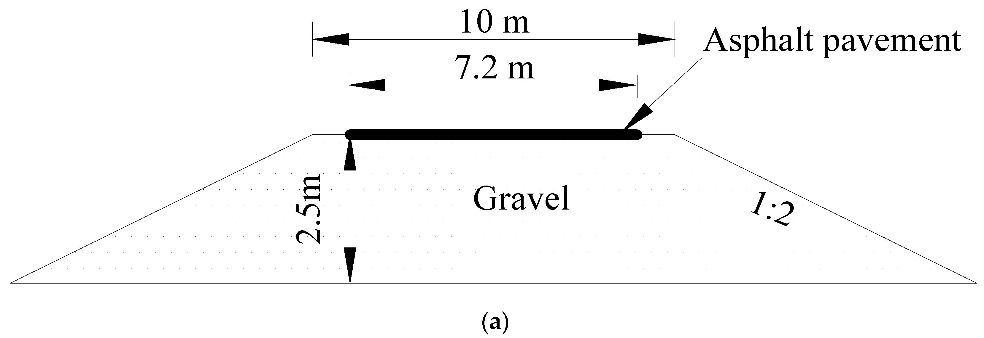
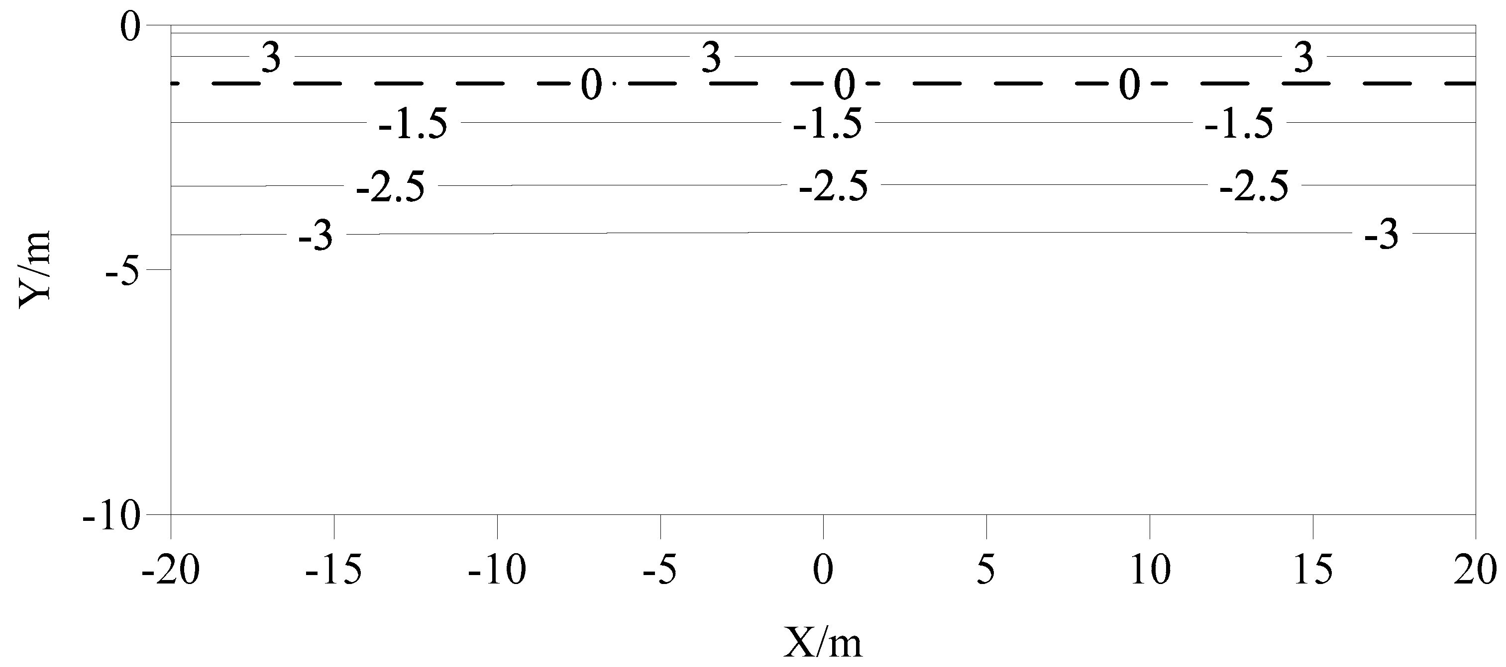
Therefore, in this study, a grey NIR reflective coating (reflecting solar radiation while maintaining a grey colour) and a sun/snow shield are combined as a composite cooling control measure. The main purpose of this research is to evaluate the cooling performance of a proposed grey NIR reflective coating–sun/snow shield embankment with asphalt pavement painted by a grey NIR reflective coating and side slopes installing sun/snow shield using a simulation method, thereby being expected to mitigate the warming effect to the underlying permafrost induced by the solar radiation and snow accumulation. The thermal regime (i.e., temperature field) evolution of a typical embankment with asphalt pavement in the Arctic permafrost region was first numerically investigated and studied 50 years after construction completion. Based on it, the thermal regimes of the typical embankments with grey NIR reflective coating, sun/snow shield, and a combination of the grey NIR reflective coating and sun/snow shield were then investigated 50 years after construction completion. The cooling performances of these three types of measures were finally evaluated by comparing the thermal regimes of these four types of embankments. The novelty of this study is mainly reflected in the combination of the grey NIR reflective coating and sun/snow shield for cooling the embankment in the Arctic regions. The proposed grey NIR reflective coating–sun/snow shield embankment can be incorporated into the design, construction, and maintenance of embankments with asphalt pavements in Arctic permafrost regions, thereby protecting the underlying permafrost from thawing and ensuring long-term safe operation.
3. Results and Analysis
3.1. For Asphalt Pavement Embankment Without Measures
Figure 5a shows the temperature distribution of the asphalt pavement embankment on 1 July of the 25th year after its completion. It can be seen from
Figure 5a that the depth of the permafrost table under the centre of the asphalt pavement was −0.24 m. The temperature distribution on 1 October of the 25th year after the embankment completion is presented in
Figure 5b. The coordinates of the permafrost table under the centre of the asphalt pavement, the left shoulder of the embankment, and the right shoulder were −1.71 m, −2.32 m, and −2.04 m, respectively. At this time, there was a certain degree of temperature asymmetry in the subgrade.
Figure 5c showed that a thaw bulb had developed in the subgrade by 1 January of the following year, and the scope of the left side of the thaw bulb was significantly larger than that of the right side. For the left side of the thaw bulb, the depths of the upper and lower boundaries were −0.61 m and −2.79 m, respectively. For the right side of the thaw bulb, the depths of the upper and lower boundaries were −0.84 m and −1.81 m, respectively. For the middle part of the thaw bulb, the depths of the upper and lower boundaries were −0.99 m and −1.33 m, respectively. The subgrade exhibited a severe “ shady and sunny slope effect”, with the temperature under the sunny slope being higher than that under the shady slope.
In general, a large cross-year thaw bulb had formed in the lower part of the subgrade under the combined effects of climate warming and subgrade engineering activities in the 25th year after its construction. This is unfavourable to the stability of the embankment.
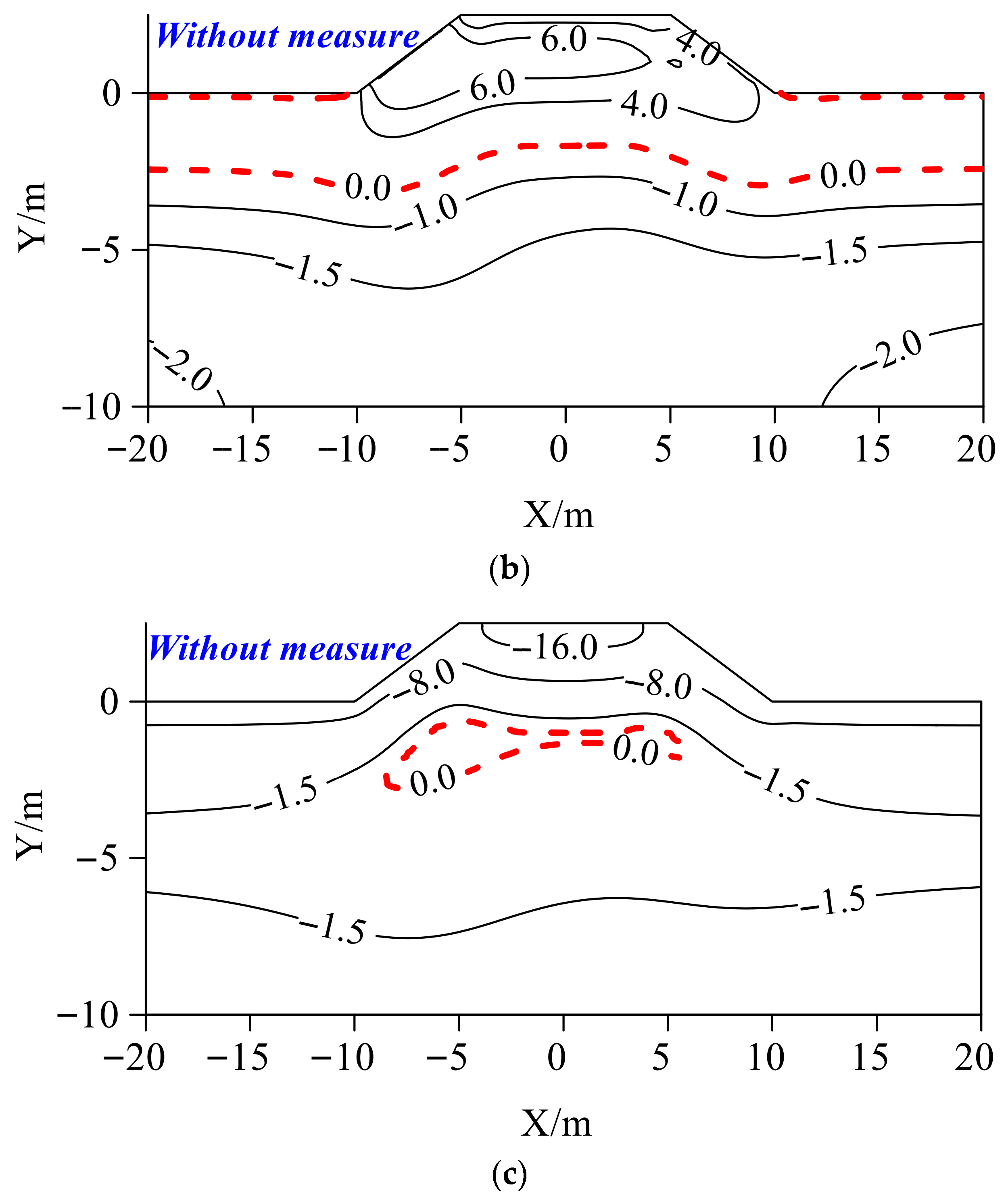
Figure 6 shows the temperature distribution of the asphalt pavement embankment 50 years after its completion.
Figure 6a presents the temperature distribution on 1 July of the 50th year after the embankment construction. At this time, the minimum temperature in the lower part of the subgrade had risen to −0.5 °C, and the depth of the permafrost table under the centre of the pavement was −0.76 m. A huge thaw bulb had formed in the lower part of the subgrade, with its maximum depth being −7.90 m. The thaw bulb was inclined toward the left side of the subgrade, i.e., the sunny-slope side of the subgrade, and extended through to the lower right part of the subgrade. The main reason for this phenomenon was the severe shady and sunny slope effect of the subgrade.
As time progresses further, by 1 October, the depth of the permafrost table under the centre of the pavement, left shoulder of embankment, right shoulder of embankment, and natural ground were −6.69 m, −7.74 m, −5.82 m, and −3.59 m, respectively. The downward movement of the permafrost table below the natural ground was mainly caused by climate warming. The depth of the permafrost table below the embankment was much lower than that below the natural ground. This indicated that the construction of the asphalt pavement embankment had accelerated the permafrost degradation in the lower part of the subgrade. By 1 January of the following year, a huge thaw bulb had developed in the subgrade (
Figure 6c), with the depth of its upper and lower boundary being −0.18 m and −8.10 m. Therefore, under the combined effects of climate warming and engineering activities, 50 years after the subgrade construction, the permafrost within a range of at least 7.92 m in the lower part of the subgrade had thawed. A huge cross-year thaw bulb had developed in the lower part of the subgrade, which will cause significant thaw settlement or even liquefaction of the subgrade, posing a very adverse impact on the stability of the embankment.
After the construction of the asphalt pavement embankment in the Arctic region, the thermal boundary of the natural underlying surface was changed. Additionally, due to climate warming, the permafrost temperature in the lower part of the subgrade had increased significantly after 50 years of operation. This poses a non-negligible threat to the stable operation of the asphalt pavement embankment.
3.2. For Grey NIR Reflective Coating Embankment
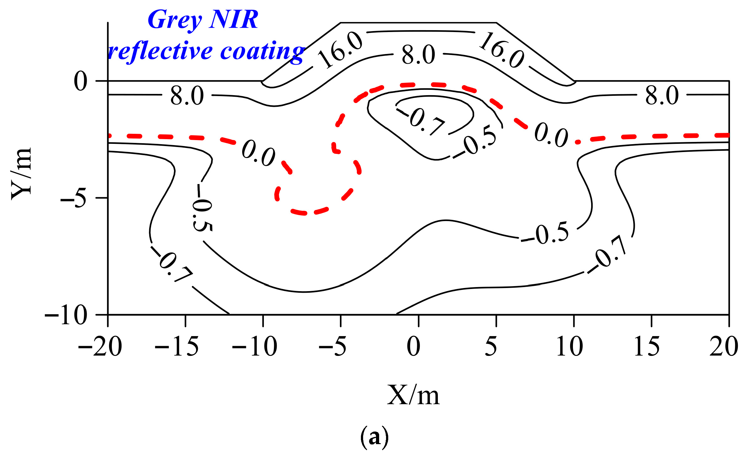
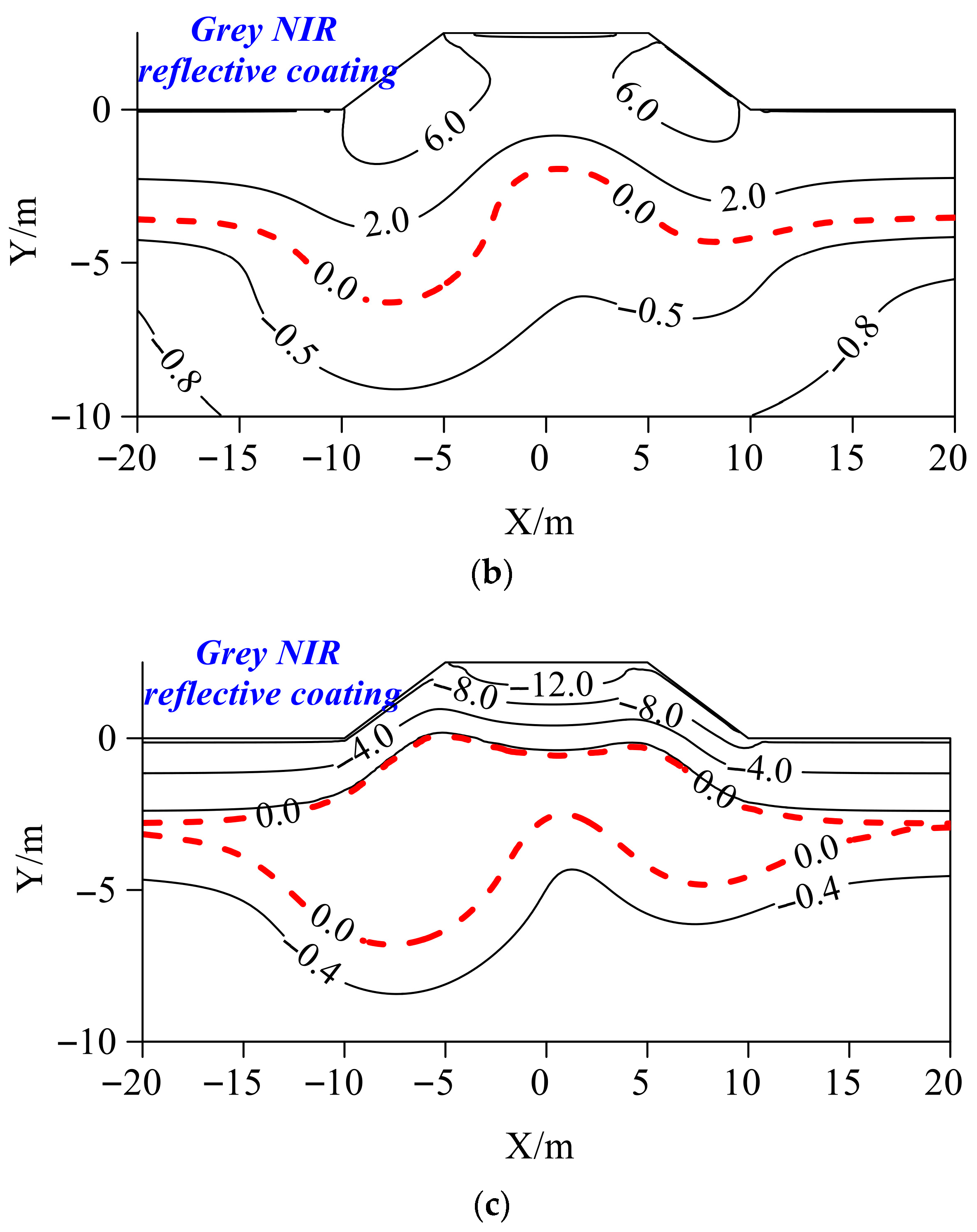
Figure 7 shows the temperature distribution of the grey NIR reflective coating embankment in the 50th year after its completion. After using the grey NIR reflective coating, the depth of the permafrost table under the centre of the pavement was −0.15 m. The region of the thaw bulb under the embankment was significantly reduced, with the maximum depth of the thaw bulb being −5.69 m. Compared with the asphalt pavement embankment without measures, the permafrost table under the embankment with the heat-reflective coating was elevated to a certain extent, and the area of the thaw bulb under the embankment was significantly reduced. It is noteworthy that, despite using the grey NIR reflective coating, a serious temperature asymmetry issue persisted in the embankment. The thaw bulb under the subgrade mainly developed on the sunny slope side of the subgrade, and the overall temperature on the sunny slope side of the subgrade was higher than that on the shady slope side.
As time progressed, the temperature distribution of the grey NIR reflective coating embankment on 1 October is shown in
Figure 7b. The depth of the permafrost table under the centre of the pavement, left shoulder of the embankment, right shoulder of the embankment, and natural ground surface were −1.95 m, −5.77 m, −3.43 m, and −3.56 m, respectively. At this point, although the grey NIR reflective coating embankment still suffered a serious problem of temperature difference between the sunny and shady slopes, the permafrost table under the centre of the pavement was significantly elevated compared with the asphalt pavement embankment without measures. Using a grey NIR reflective coating can alleviate the degradation of the permafrost under the embankment to a certain extent. By 1 January of the following year, the grey NIR reflective coating embankment cannot be completely refrozen, and a cross-year thaw bulb has developed under the subgrade (with depths of the upper and lower boundaries being −0.00 m and −6.81 m). Although this thaw bulb was slightly smaller than that of the unprotected embankment, it still had a great impact on the embankment stability.
In general, the grey NIR reflective coating mainly cooled the embankment through the pavement and cannot change the serious sunny-shady slope effect of the embankment. After 50 years of operation, the subgrade cannot be completely refrozen, and the permafrost has seriously degraded, which is not conducive to the stability of the permafrost.
3.3. For Sun/Snow Shield Embankment
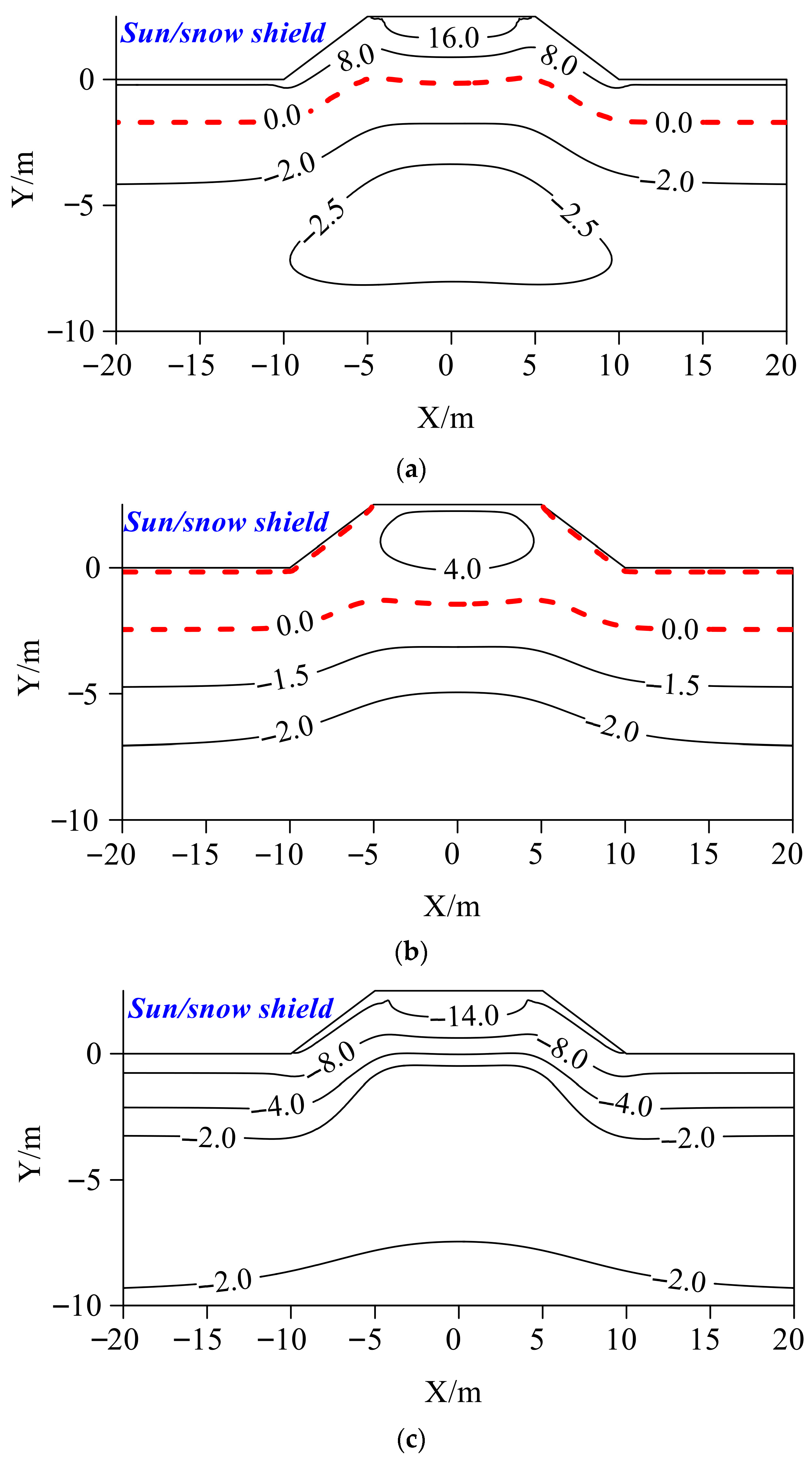
Figure 8 shows the temperature distribution of the sun/snow shield embankment in the 25th year after its completion. After the construction of the sun/snow shield embankment, compared with the unprotected embankment, the temperature under the embankment was effectively reduced, and the temperature field distribution was symmetrical. Specifically, on 1 July of the 25th year after completion, a low-temperature core of −2.5 °C appeared under the sun/snow shield embankment (
Figure 8a). On 1 October of the 25th year after the embankment construction, the temperature under the embankment was lower than that at the same depth under the natural ground surface. For example, the isotherms of −2.0 °C and −1.5 °C were elevated in the middle of the subgrade. The temperature under this embankment is significantly lower than that under the unprotected embankment. The −2.0 °C isotherm under the unprotected embankment had disappeared, while the −2.0 °C isotherm under the sun/snow shield embankment still existed and was elevated to a certain extent. By 1 January of the following year, as shown in
Figure 8c, the sun/snow shield embankment had been completely refrozen, and the temperature under the subgrade was significantly lower than that under the natural ground surface.
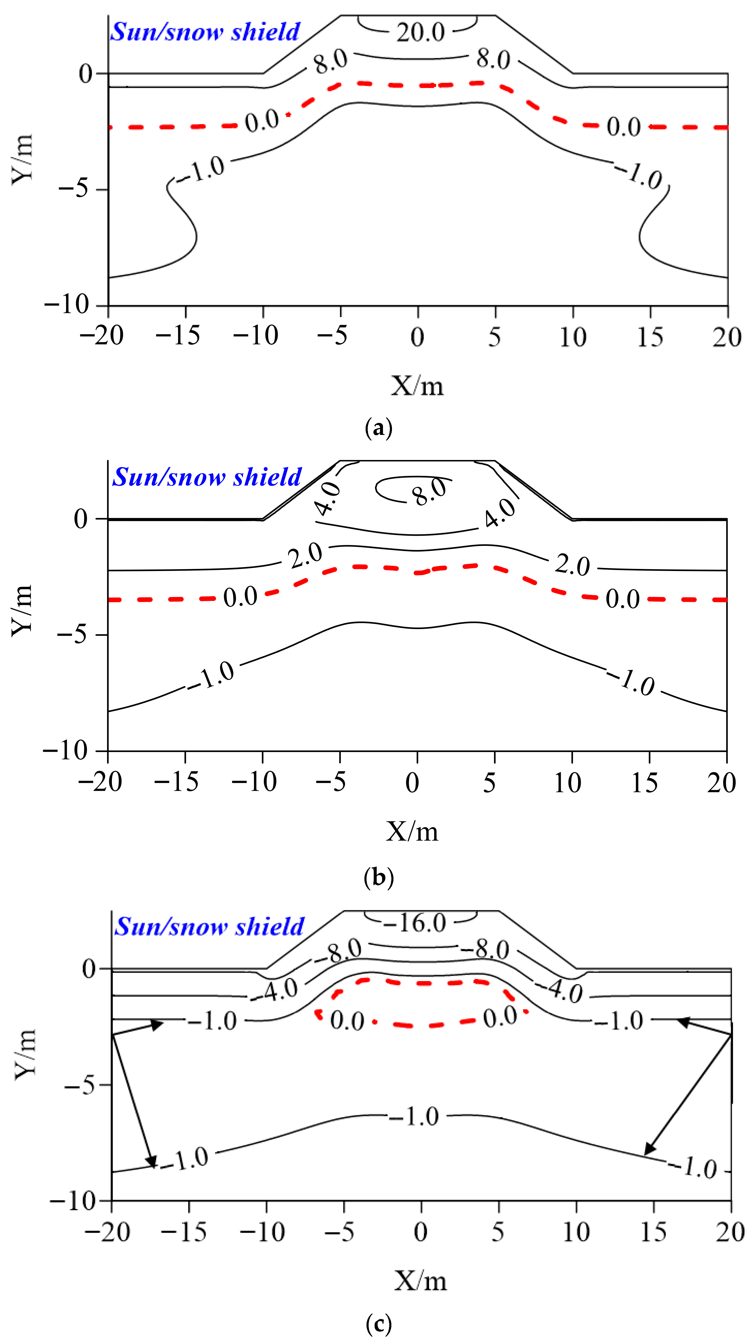
Figure 9 presents the temperature distribution of the sun/snow shield embankment 50 years after its construction. After adopting the sun/snow shield, the temperature distribution on 1 July of the 50th year after the embankment construction is shown in
Figure 9a. At this time, there was no large-scale thaw bulb developed under the embankment. The depth of the permafrost table under the centre of the pavement was −0.53 m. The temperature distribution was symmetrical, and no sunny-shady slope effect in the embankment was observed. In contrast, a large-scale thaw bulb had appeared under the unprotected embankment at this time. By 1 October, the depth of the permafrost table under the centre of the pavement, left shoulder of the embankment, right shoulder of the embankment, and under the natural ground surface were −2.34 m, −2.13 m, −2.13 m, and −3.53 m, respectively.
Comparing that under the natural ground surface and centre of the pavement, it can be seen that the sun/snow shield had an obvious cooling effect on the subgrade, which can mitigate the permafrost degradation caused by climate warming and embankment construction. In addition, according to
Figure 9c, after adopting the sun/snow shield, the subgrade still cannot be completely refrozen. However, compared with the unprotected subgrade, the temperature under the subgrade with this measure was significantly reduced. The depths of the upper and lower boundaries of the thaw bulb under the sun/snow shield were −0.64 m and −2.47 m, respectively. The region of this thaw bulb was significantly smaller than that of the thaw bulb under the unprotected embankment after 50 years of operation.
In general, the sun/snow shield showed a good cooling effect on the permafrost under the embankment, but there was still room for improvement in its cooling performance. The cooling capacity of the sun/snow shield for the embankment was mainly achieved through cooling the two sides of the slope. In view of this, the grey NIR reflective coating can be used in combination with the sun/snow shield. It is expected that this combination can cool the embankment in the Arctic simultaneously from the pavement and slope, thereby realising the thermal protection of the asphalt pavement embankment in typical Arctic regions.
3.4. For Grey NIR Reflective Coating–Sun/Snow Shield Embankment
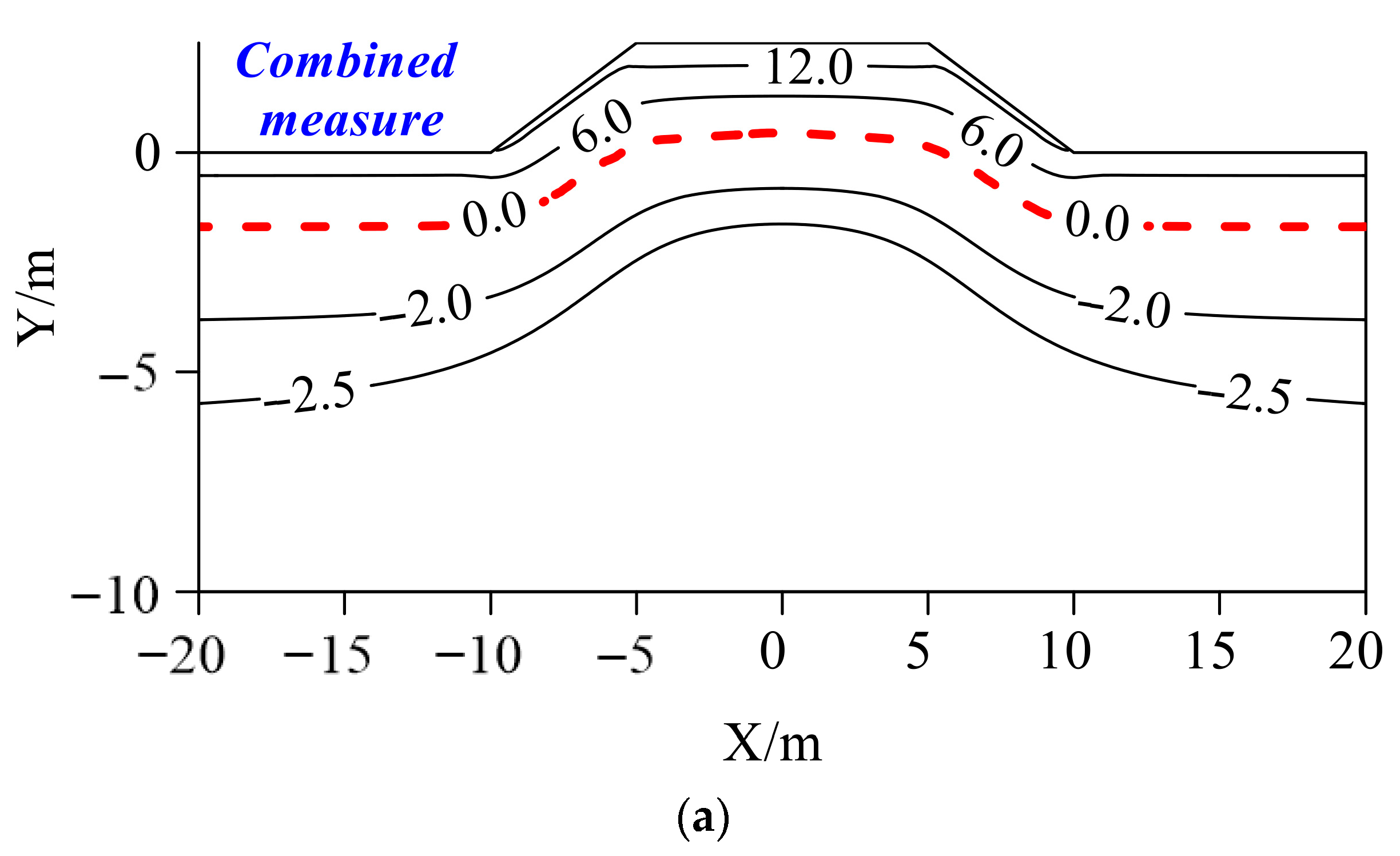
Figure 10 shows the temperature distribution of the grey NIR reflective coating–sun/snow shield embankment in the 25th year after its construction. On 1 July of the 25th year, the 0 °C isotherm under the subgrade had extended into the embankment, with a coordinate of y = 0.45 m. Meanwhile, a −2.5 °C isotherm had appeared under the subgrade with grey NIR reflective coating and sun/snow shield (
Figure 10a), and the temperature was significantly lower than that of the unprotected embankment. By 1 October, the depth of the 0 °C isotherm under the grey NIR reflective coating–sun/snow shield embankment was −0.51 m (
Figure 10b), while that under the unprotected embankment at this time was −1.71 m. The combination of grey NIR reflective coating–sun/snow shield can effectively reduce the temperature under the embankment. The −2.0 °C isotherm under the unprotected embankment had disappeared, but the −2.0 °C isotherm under the grey NIR reflective coating–sun/snow shield embankment still existed and had been elevated to a certain extent (
Figure 10b). A combination of grey NIR reflective coating and sun/snow shield had basically solved the shady–sunny slope effect of the subgrade. The temperature under grey NIR reflective coating–sun/snow shield embankment was lower than that at the same depth under the natural ground surface. For instance, the −2.0 °C and −1.5 °C isotherms had been elevated under the grey NIR reflective coating–sun/snow shield embankment, which indicated that the combination of the grey NIR reflective coating and sun/snow shield can effectively mitigate the permafrost degradation caused by climate warming and engineering activities. Furthermore, by 1 January of the following year, the grey NIR reflective coating–sun/snow shield embankment had been completely refrozen, and the temperature under the embankment was significantly lower than that under the natural ground surface. In contrast, the unprotected embankment has not been completely refrozen, under which a thaw bulb had developed.
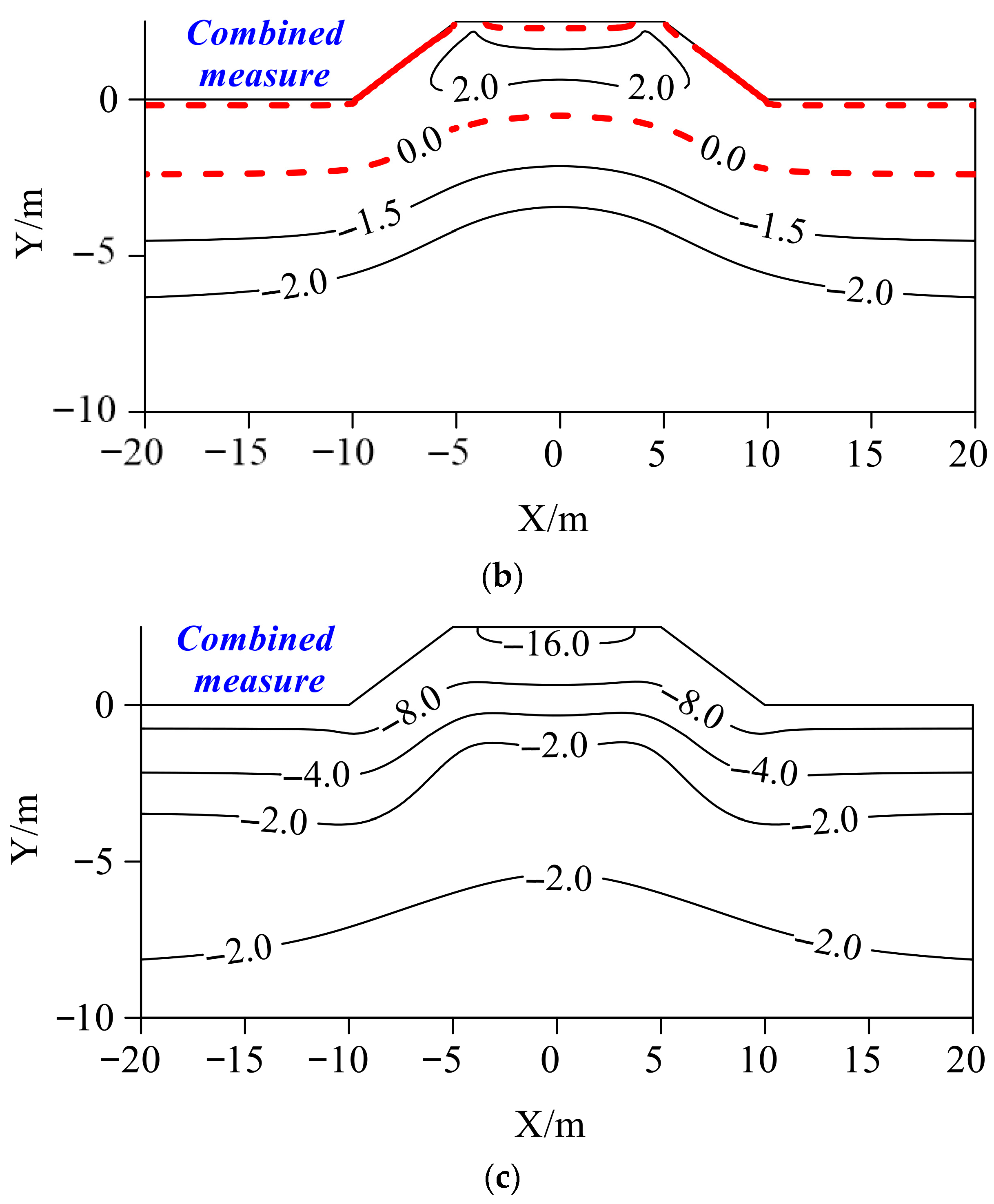
Figure 11 shows the temperature distribution of the grey NIR reflective coating–sun/snow shield embankment in the 50th year after its construction. After adopting the combined measure of grey NIR reflective coating and sun/snow shield, the temperature under the subgrade was low, and the temperature distribution was uniform. Specifically, regarding the temperature field distribution on 1 July of the 50th year after the subgrade construction (
Figure 11a), the depth of the permafrost table under grey NIR reflective coating–sun/snow shield embankment was 0.04 m (above the natural ground), and a low-temperature core of −1.5 °C had developed. In contrast, a large-scale thaw bulb had appeared under the unprotected embankment.
By 1 October, no large-scale thaw bulb had developed under the grey NIR reflective coating–sun/snow shield embankment. The depth of the permafrost table under the centre of the pavement, left shoulder of the embankment, right shoulder of the embankment, and under natural ground surface were −1.21 m, −1.78 m, −1.78 m, and −3.47 m, respectively. At this time, a large-scale thaw bulb had developed under the unprotected embankment, which indicated the effectiveness of the grey NIR reflective coating and sun/snow shield in cooling the subgrade (
Figure 11b).
Figure 11c shows that the grey NIR reflective coating–sun/snow shield embankment had been completely refrozen, whereas there was a large 0 °C thaw bulb under the unprotected embankment.
3.5. Comparison of Four Types of Embankments
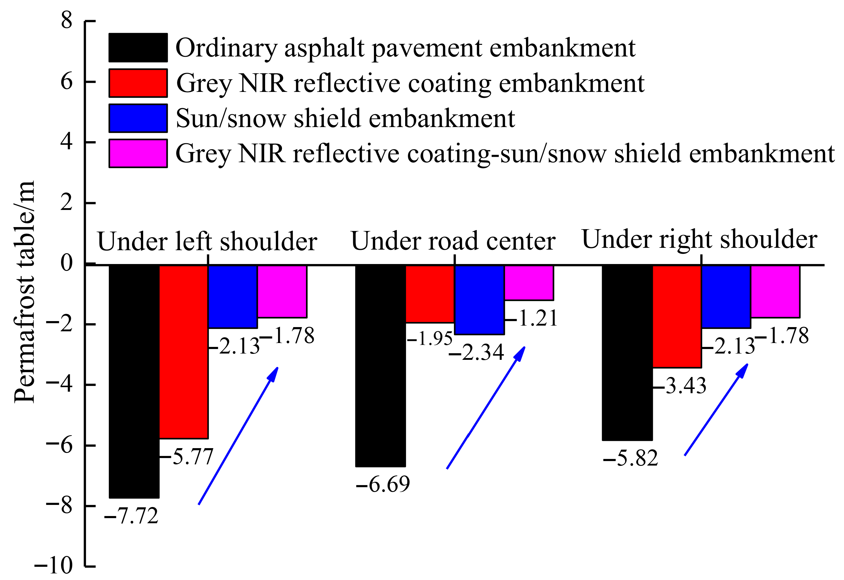
Figure 12 presents the Permafrost tables under the embankments with different measures as of 1 October in the 50th year after construction. By using different control measures for embankment, the permafrost tables at different positions (under the left road shoulder, under the road centre, and under the right road shoulder) of the subgrade were significantly different on 1 October of the 50th year after the subgrade construction.
First, the permafrost tables under the left and right road shoulders of the embankment with different measures are analysed. For the asphalt pavement embankment, the grey NIR reflective coating embankment, sun/snow shield embankment, and grey NIR reflective coating–sun/snow shield embankment, the depths of the permafrost tables under the left road shoulders were −7.72 m, −5.77 m, −2.13 m, and −1.78 m, respectively; the depths of the permafrost tables under the right road shoulders were −5.82 m, −3.43 m, −2.13 m, and −1.78 m, respectively. After adopting the grey NIR reflective coating, although the permafrost tables under the left and right road shoulders of the embankment were lifted to a certain extent, the shady and sunny slope effect still existed. After adopting the sun/snow shield or a combination of grey NIR reflective coating and sun/snow shield, the permafrost tables under the left and right road shoulders of the subgrade were all lifted, and the depth of the permafrost tables was consistent. This indicates that both the sun/snow shield and the combination of grey NIR reflective coating and sun/snow shield can solve the shady and sunny slope effect, and show a good cooling effect on the subgrade. The permafrost table under the left and right road shoulders of the grey NIR reflective coating–sun/snow shield embankment was −1.74 m, which was higher than that of the sun/snow shield embankment (−2.30 m) and even higher than that of the grey NIR reflective coating embankment. In terms of the cooling capacity of the slopes on both sides of the embankment, the cooling effect of the combination of grey NIR reflective coating and sun/snow shield was better than that of the sun/snow shield measure. This showed that the sun/snow shield focused on cooling from both sides of the embankment slope, while the combination of grey NIR reflective coating and sun/snow shield cooled both the embankment surface and the slope at the same time.
Second, the permafrost table under the road centre of the embankment with different measures is analysed. For the asphalt pavement embankment, the grey NIR reflective coating embankment, the sun/snow shield embankment, and grey NIR reflective coating–sun/snow shield embankment, the depths of the permafrost tables under the road centre of the embankments were −6.69 m, −1.95 m, −2.34 m, and −1.21 m, respectively. No matter which measure was adopted, the permafrost table under the road centre of the embankment was significantly lifted. In terms of the cooling capacity of the road surface of the embankment, the combination of grey NIR reflective coating and sun/snow shield exhibited the best cooling effect, followed by the grey NIR reflective coating measure, and the sun/snow shield measure showed the worst effect. It further indicated that the grey NIR reflective coating measure focused on cooling from the road surface of the embankment, while the combination of grey NIR reflective coating and sun/snow shield cooled both the embankment surface and the slope at the same time.
On 1 January of the 50th year after the embankment construction was completed, there were also significant differences in the lower part of the subgrade with different measures. For the asphalt pavement without protective measures, an inter-annual thaw bulb developed in its lower part, with the depths of the upper and lower boundary being −0.18 m and −8.10 m, respectively. For the grey NIR reflective coating embankment, an inter-annual thaw bulb also developed in its lower part, with the depths of the upper and lower boundary being −0.00 m and −6.81 m, respectively. For the sun/snow shield embankment, an inter-annual thaw bulb also developed in the lower part of the subgrade, with the depths of the upper and lower boundary being −0.64 m and −2.47 m, respectively. For the grey NIR reflective coating–sun/snow shield embankment, no inter-annual thaw bulb developed in its lower part.
In general, these three measures can significantly increase the permafrost table under sunny slope by 25.25%, 72.41% and 76.94%, under asphalt pavement by 70.85%, 65.02% and 81.91%, and under shady slope by 41.07%, 63.40% and 69.42%. Based on the above analysis, the combination of grey NIR reflective coating and sun/snow shield exhibited the best cooling effect, followed by the sun/snow shield measure, and the grey NIR reflective coating measure showed the worst cooling effect.
4. Discussion
In order to mitigate the warming effect on underlying permafrost induced by the solar radiation and snow accumulation, the grey NIR reflective coating and sun/snow shield were first combined to propose a grey NIR reflective coating–sun/snow shield embankment. Numerical simulation showed that this new proposed embankment can cool the underlying permafrost from the asphalt pavement and the two side slopes, and obtain an excellent cooling effect. The shady–sunny slope effect of the embankment was solved successfully. After operating for 50 years, on 1 October, no large-scale thaw bulb had developed under the grey NIR reflective coating–sun/snow shield embankment.
The mechanism cooling the underlying permafrost of the proposed grey NIR coating–sun/snow shield embankment was attributed to the following aspects: (a) The grey NIR coating has a high reflectivity for near—infrared light. It can reflect a large amount of solar radiation back into the environment, reducing the heat absorbed by the embankment surface. As a result, the temperature of the embankment surface and the underlying soil decreases, thus reducing the heat transfer to the permafrost and playing a role in cooling the permafrost. (b) a sun/snow shield can quickly and effectively reduce the net radiation amount and heat flux entering the embankment surface, thereby lowering the temperature of the embankment surface and the interior of the soil mass, and improving the temperature field of the embankment soil mass. (c) a sun/snow shield can prevent the snow accumulation in the winter, and thus solve the insulation effect induced by snow accumulation on two side slopes. (d) during the freezing season, the air convection under the sun/snow shield can increase the sensible heat exchange.
In this study, we focus on evaluating the cooling performance of a proposed grey NIR reflective coating–sun/snow shield embankment with asphalt pavement painted by a grey NIR reflective coating and side slopes installing sun/snow shield using a simulation method. Therefore, the obtained results are not validated in this study. This study is a preliminary work on the grey NIR reflective coating–sun/snow shield embankment. The validation of the results will be conducted in the next step. First, a model test on this grey NIR reflective coating–sun/snow shield embankment under the simulated Arctic climate condition should be carried out to study the temperature field variation. Second, the grey NIR reflective coating–sun/snow shield embankment should be constructed in a typical Arctic region to monitor the temperature variation. Third, by combining the results of the indoor model test with the field test, the effectiveness of the proposed grey NIR reflective coating–sun/snow shield embankment in cooling the permafrost in the Arctic region can be evaluated and verified.
It should be noted that only the temperature field is studied, and the moisture and deformation are ignored in this paper. The moisture and deformation of soil in embankments are also important for the stability of embankments. In the future, the thermal-moisture-deformation field of the grey NIR reflective coating–sun/snow shield embankment warrants detailed investigation and study.

