1. Introduction
The 21st century has witnessed a boom in the development of tunnels and underground space [
1]. With the continuous advancement of social and economic levels and the growing demand of people for an improved quality of life, the scale and quantity of transportation and engineering construction in China have generally shown an upward trend [
2]. Statistical data indicate that by the end of 2020, China’s railway mileage had reached 145,000 km, among which a total of 16,798 railway tunnels were put into operation, with an aggregate length of approximately 19,630 km. An analysis of statistical data from previous years [
3,
4] reveals that over the 40-year period from 1980 to 2020, a total of 12,412 tunnels were constructed in China, with a total length of about 17,621 km (accounting for 90% of the total length of China’s railway tunnels). In recent years, with a number of century-old projects represented by the Yarlung Tsangpo River downstream project and the Sichuan-Tibet Railway being put on the agenda, China’s tunnel construction has entered a new era. This not only puts forward higher requirements for the development and application of intelligent tunnel construction technologies but also provides a broad practical platform for the intelligent construction of tunnels, enabling the full application of new construction theories, methods, equipment, and technologies [
5].
With the advancing development of science and technology, the Ministry of Housing and Urban-Rural Development has issued the Guiding Opinions on Promoting the Synergistic Development of Intelligent Construction and Construction Industrialization, which proposes the necessity of expanding the application of intelligent construction across all aspects of engineering construction and establishing an intelligent construction industry system that covers the entire industrial chain, including scientific research, design, production and processing, construction and assembly, as well as operation. The 14th Five-Year Plan for the Development of the Construction Industry explicitly states that by 2025, the industrialization, digitization, and intellectualization levels of the construction sector must be significantly enhanced, and a policy system and industrial framework for the synergistic development of intelligent construction and the new industrialization of construction should be basically established. Driven by the complexity of tunnel construction, the arrival of the intelligent era, the integration of intelligent information technologies, and the support of national policies, the development of intelligent tunnel construction technologies has been strongly promoted, with an increasing number of intelligent equipment, working methods, and technologies being applied in the field of tunnel construction [
6].
In October 2022, the Ministry of Housing and Urban-Rural Development (MOHURD) selected 24 cities to carry out pilot projects for intelligent construction, among which Xiong’an New Area—a state-level new area designated by the Central Committee of the Communist Party of China (CPC) and the State Council—was included. Promoting the development of industrialized and intelligent construction, and upgrading the scale of such construction, constitutes the mission of Xiong’an New Area’s development and serves as a guarantee for the comprehensive implementation of the guideline of “building Xiong’an New Area with high standards and high quality.” The underground section civil engineering and related supporting projects of the Xiongxin High-Speed Railway in Xiong’an New Area are located in the start-up zone of Xiong’an New Area. They shoulder the important task of centrally undertaking the relocation of Beijing’s non-capital functions in the current era and assume a demonstrative and leading role in establishing the “Xiong’an Quality” model, which adheres to the standard of “world vision.” It is a high-starting-point project characterized by green ecology and sustainable development.
The Xiongxin High-Speed Railway is a key component of the Beijing-Kunming Passage in China’s high-speed railway network, facilitating passenger exchanges via the railway network between Northwest China, Southwest China, North China, and Northeast China. It functions as an inter-regional high-speed passenger line supporting rapid passenger flows between the Beijing–Tianjin–Hebei urban agglomeration and the Jinzhong urban agglomeration, while also accommodating inter-city passenger and tourist flows and poverty alleviation and development functions among cities along the line. Additionally, the section from Xiong’an to Baoding East serves as one of the main passenger transportation axes in the Beijing–Tianjin–Hebei intercity railway network, acting as the primary intercity passenger line within the Beijing-Baoding-Shijiazhuang corridor and a new type of rail express line integrating public transportation services between town clusters along the route. The Xiong’an section of the Xiongxin High-Speed Railway extends southward from Xiong’an Station (interconnected with the Beijing-Xiong’an Intercity Railway), crosses the New Gaifang Floodway, turns westward, passes under the Baigou River via tunneling, traverses the start-up zone of Xiong’an New Area along the planned east–west axis in the form of a tunnel, includes Xiong’an Intercity Station in the start-up zone cluster, reserves Xiaoli Station in the first cluster, and exits the ground after passing under the Pinghe River into Xushui District, Baoding City.
Currently, common tunnel construction methods can be categorized into four types: open-cut, underground excavation, shield, and immersed tube methods. The open-cut method is subdivided into conventional open-cut and cover-excavation reverse methods. Underground excavation methods generally include mining, the New Austrian Tunneling Method (NATM), and shallow tunneling, among others. Shield methods are classified into air-pressure, Earth Pressure Balance (EPB), and slurry shield technologies. Immersed tube methods encompass dry dock and steel shell approaches [
7].
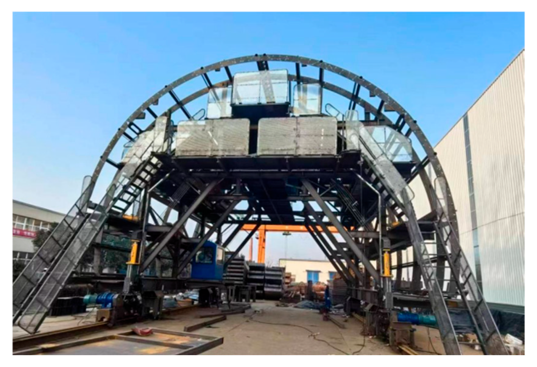
In underground excavation projects both domestically and internationally, trolleys are commonly used in construction. Traditional trolleys rely on single-point manual operations for movement and formwork stripping, lacking effective centralized control and safety monitoring. Lining rebar installation is performed on formwork trolleys; however, traditional rebar trolleys are mostly fabricated on-site by work teams without hydraulic systems or reinforcement clamps, resulting in low precision in rebar placement. These rebar trolleys also lack automated walking, positioning, and adjustment systems, leading to inefficient movement and alignment. Additionally, pedestrian passages and edge protection are simplistic in design, with poor structural rigidity and stability posing potential safety risks. Moreover, rebar lifting and positioning require significant labor input and carry high safety risks.
Traditional maintenance of concrete structures in underground engineering primarily involves manual sprinkling and geotextile covering, which are inefficient and result in slow strength development. This not only delays construction progress but also indirectly increases project costs. Due to disjointed processes and large age differences between arch and lining concrete, the shrinkage characteristics of lining and arch concrete exhibit variability induced by time lags. This has led to diagonal through-cracks in concrete structures even before project commissioning, exceeding the limit state for normal use of concrete structures and compromising structural durability and safety. Furthermore, traditional waterproofing systems are constrained by construction technology limitations, featuring poor toughness and inconsistent quality, which result in frequent leakage issues during tunnel operation.
The open-cut method is characterized by six key features: (1) Open-air construction, where construction duration and quality are significantly affected by weather conditions; (2) multiple work zones with cross-operation of various trades, leading to complex construction organization and implementation that is difficult to control comprehensively; (3) parallel execution of multiple processes in open workspaces, enabling improved construction efficiency; (4) lack of inter-process coordination, resulting in low workflow efficiency; (5) low specialization of professional construction equipment, with processes such as rebar binding constraining the critical path of the construction schedule; and (6) low automation of construction machinery.
Focusing on the 2# and 3# open-cut tunnels of the Xiongxin High-Speed Railway, this study establishes a comprehensive intelligent construction system for long open-cut tunnels. Addressing the practical needs of the project, it investigates key technologies and integrated equipment for modular intelligent construction of long open-cut tunnels, aiming to effectively enhance construction progress and quality while further advancing the intelligent construction level of open-cut tunnels in China.
3. Modular Intelligent Construction System for Open-Cut Tunnels
Owing to the fundamental differences in construction processes between open-cut tunnels and bored tunnels, this study examines the disparities in their construction workflows, draws on the support provided by intelligent construction throughout the entire process of bored tunnel construction, and takes into account the key challenges and quality issues in open-cut tunnel construction that cannot be resolved by traditional methods. By integrating multi-source heterogeneous database construction, Building Information Modeling (BIM), three-dimensional laser scanning, and other cutting-edge information technologies, the development and application of intelligent equipment are being advanced.
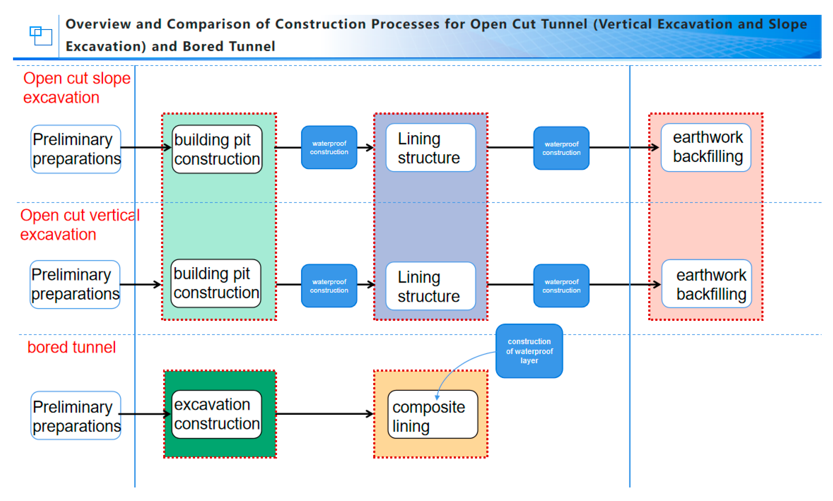
Based on the differences in construction processes between the open-cut method and the bored method (
Figure 6), a comparison is made of the two construction methods in terms of intelligent construction.
The construction process of open-cut tunnels can be categorized into vertical and sloped types based on the foundation pit excavation method (
Figure 7). The sloped type adopts a waterproof screen and a sprayed anchor slope support system, whereas the vertical type utilizes a drilled grouting pile, waterproof screen, and rebar bracing system. Owing to these differences in support systems, variations exist in the construction processes of open-cut tunnels.
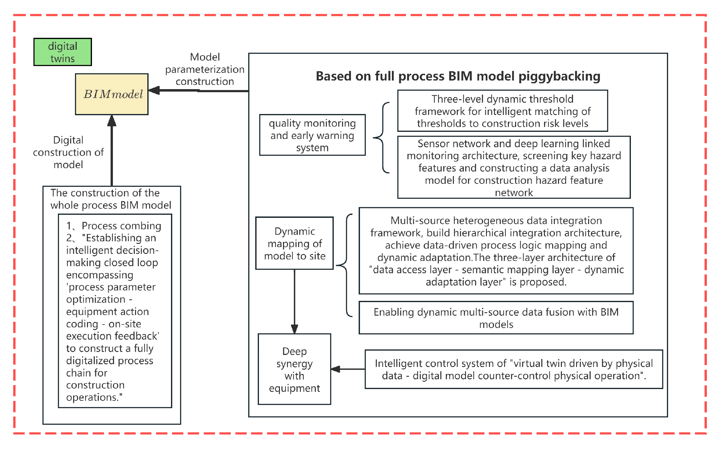
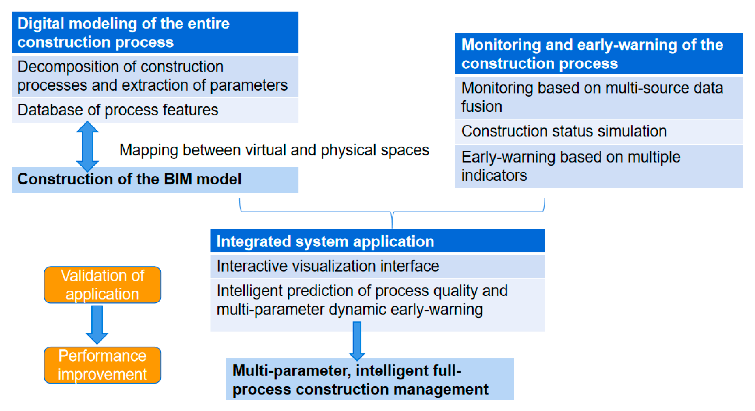
Leveraging the digital twin of the full-process control model for open-cut tunnels, this study aims to achieve multi-parameter and multi-modulus refined construction management in a three-dimensional virtual construction scenario. To systematically sort out the full-process overlapping and cross operations in open-cut tunnels and construct a 3D BIM model for each process, the steps of BIM are divided into four-dimensional modeling, parametric modeling, and digital modeling (
Figure 8). Firstly, the construction process of the open-cut tunnel is sorted out, and intelligent decision-making is used to digitize the process chain. Secondly, a quality monitoring and early warning system is deployed, enabling the fusion of dynamic multi-source data with the BIM model to map dynamic scenes onto the model. Finally, a visualization platform is built to support remote control.
The concept of modularization is proposed in the intelligent construction system for open-cut tunnels, based on the entire process of construction sequencing. Modularization refers to the process of solving complex problems by dividing a system into several modules from top to bottom, where each module performs a specific sub-function or forms a single structure suitable for sub-projects. All modules are then assembled in a certain manner to form an integrated whole, thereby fulfilling the functions required by the entire system. The process of implementing modularization is termed modular construction [
23].
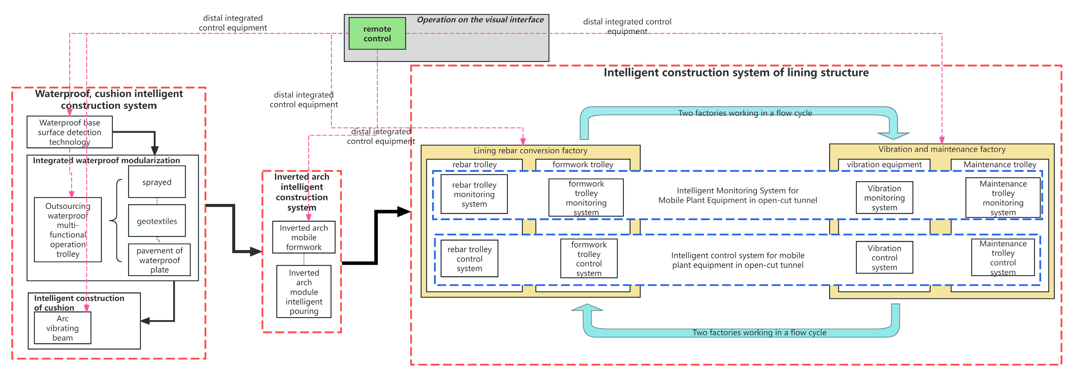
According to the construction process, open-cut tunnels are divided into three modules: the waterproofing and cushion module, the inverted arch module, and the lining structure module. Together with the digital twin and remote control module, which runs through the three construction modules, a total of four modules form the system. By using R&D software and equipment, factory-style construction is realized on-site. Each module cooperates and works alternately, forming an optimal overlap of flow operations and reducing the impact of flow steps on the construction period.
Taking the open-cut tunnel section of the Xiongxin High-speed Railway as the research object, this paper proposes a whole-process modular intelligent construction system based on the entire construction process of open-cut tunnels (
Figure 9). This system integrates the key construction steps of open-cut tunnels to form a comprehensive whole-process modular intelligent construction system. Through practical application in the project, it aims to provide a reference for the development of intelligent construction in open-cut tunnel engineering in China.
4. Intelligent Construction Technology of Open-Cut Tunnel
Intelligent construction technology constitutes the core of the entire intelligent construction system. By leveraging modern information technologies to achieve intelligent goals and supporting project construction, it innovates the previous experience-based construction methods: each construction step is quantified, the results obtained are more accurate, ensuring strict uniformity of all components and reliable quality control. Traditional tunnel construction quality management still relies on the conventional Plan-Do-Check-Act (PDCA) system [
24], which depends heavily on the management capabilities and sense of responsibility of full-time quality management personnel on-site, as well as the construction skills of operators. Quality control is implemented through self-inspection, mutual inspection, cross-inspection, and even involves third-party supervision through parallel contracting.
Based on the Xiongxin Railway open-cut tunnel project, the key technology for modular intelligent construction of high-speed railway open-cut tunnels is developed around the main line of the open-cut tunnel construction process, establishing four major modules: the waterproofing and cushion module, the inverted arch module, the lining structure module, and the digital twin and remote control module.
In line with the concept of these four modules for open-cut tunnels, four technologies are proposed: waterproof base surface detection technology, rebar system transformation technology, self-sensing maintenance technology, and equipment cluster remote control technology.
4.1. Waterproof Base Surface Detection Technology
Traditional inspection methods involve using hand tools such as rulers and levels to assess the flatness and perpendicularity of the supporting surface through manual measurement and visual inspection [
25]. Most current imaging technologies are limited to visible light imaging, which results in poor image specificity in certain applications, making image detection and identification challenging. For this reason, it is necessary to conduct comprehensive research on imaging technologies from aspects such as light source, light intensity, spectral control, precision optical control, advanced array sensing, and signal conditioning. This includes investigating the interaction between different objects and electromagnetic waves, as well as new phenomena, principles, and methods related to imaging. A variety of advanced imaging technologies—such as laser scanning imaging, weak interference imaging, chromatographic imaging, terahertz imaging, and capacitive imaging—have been applied to industrial vision detection and control, enriching visual perception methods [
26].
To address the technical problems of difficulty in controlling the flatness of the initial shotcrete base surface in the side wall section of open-cut tunnels and low efficiency of traditional detection, this study innovatively proposes an intelligent flatness detection algorithm based on three-dimensional LiDAR scanning.
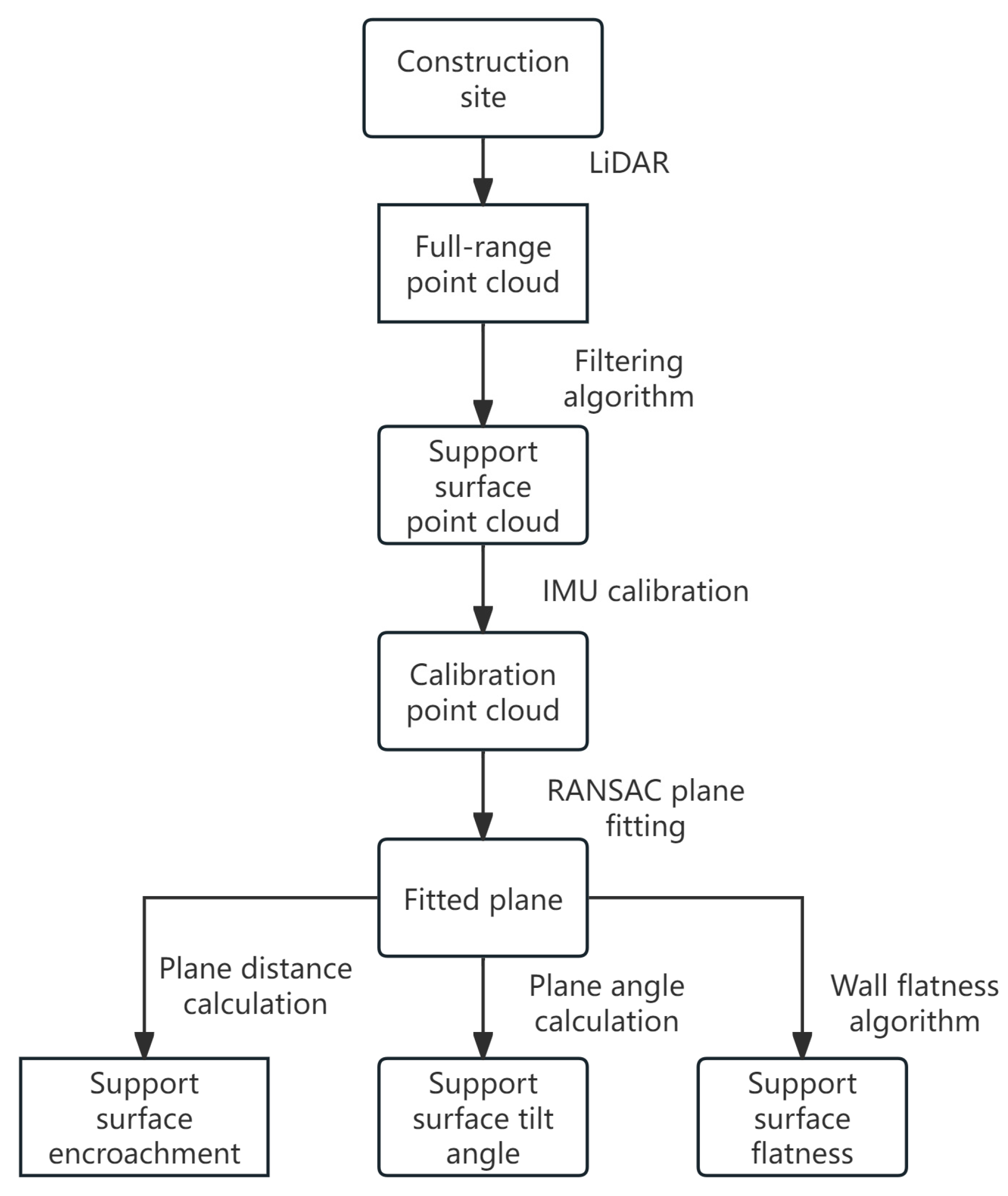
The overall detection process of this device is shown in
Figure 10. First, the point cloud of the construction site is collected using LiDAR. Then, the point cloud is preprocessed to obtain the calibrated wall point cloud data. The data is then sent into the encroachment detection module, tilt angle measurement module, and flatness detection module, respectively, to obtain the corresponding detection results.
The entire system consists of four components: LiDAR, a triangular bracket, an external power supply, and a host computer. The 3D laser scanning system typically employs non-contact high-speed laser measurement to acquire 3D data of object surfaces and large-area terrain, referred to as point cloud data [
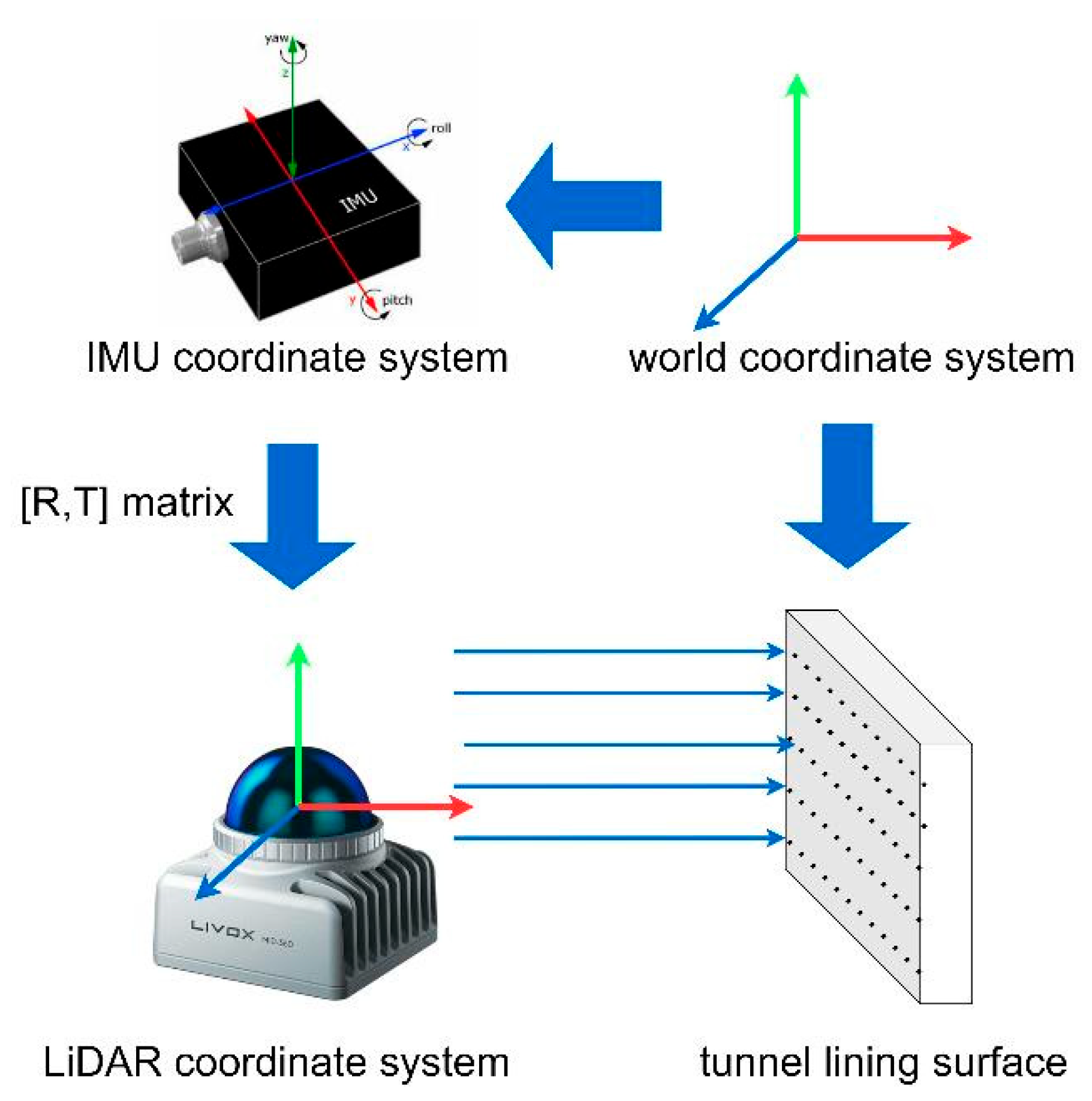
27]. To enhance the accuracy and stability of subsequent fitting algorithms, point cloud data preprocessing includes denoising, filtering, and data alignment. Since construction sites may not always meet the requirements for level measurement, the LiDAR may be placed at a tilt angle. In such cases, it is necessary to combine an Inertial Measurement Unit (IMU) (
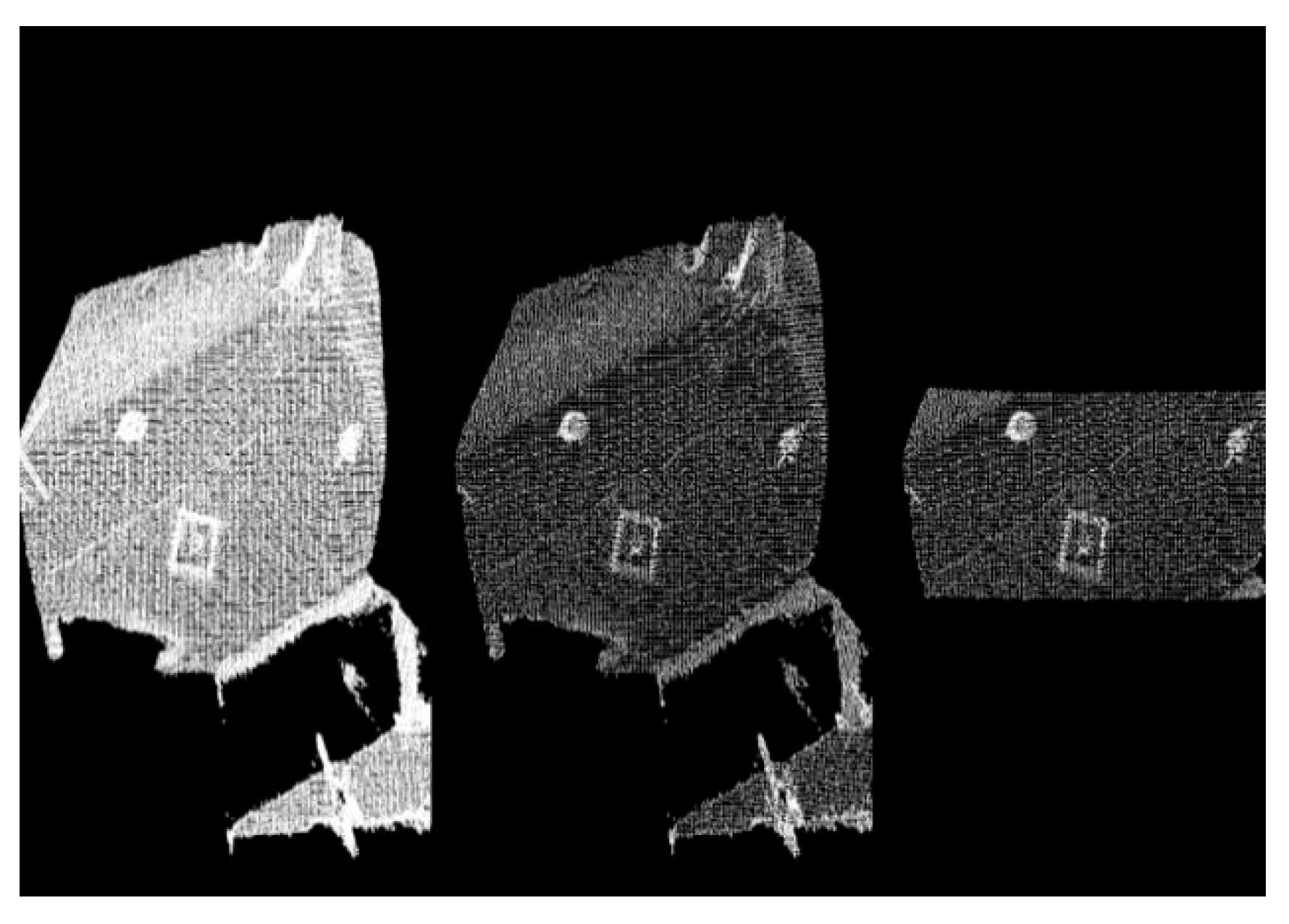
Figure 11) to horizontally calibrate the collected raw point cloud data. Point cloud denoising adopts the straight-pass filtering algorithm (
Figure 12), which involves specifying coordinate axes (X, Y, Z) in any direction, defining coordinate ranges, and cropping to retain the required portion of the point cloud [
28].
For tunnel support surface scenarios, a universal standard for flatness calculation and measurement is defined, incorporating three weight coefficients. These weight parameters can be adjusted according to specific requirements to accommodate diverse application scenarios.
In terms of the defect localization algorithm, the Canny edge detection algorithm is employed to conduct preliminary edge identification of holes within the projected point set. Once the hole contours are obtained, the Minimum Bounding Rectangle (MBR) method is used to fit these contours, enabling more precise localization of the geometric center of each hole.
Building on the fitted plane, improvements are made to the detection of support surface verticality, support surface intrusion, and flatness measurement.
Based on an improved Random Sample Consensus (RANSAC) algorithm, a spatially distributed sampling strategy is adopted to divide the support surface into several larger regions. At each iteration, three regions are randomly selected, and one point is sampled from each region to ensure uniform distribution of sample points across the entire support surface (
Figure 13). Compute Unified Device Architecture (CUDA) technology is used to accelerate the plane fitting algorithm for the support surface point cloud, and the CUDA-accelerated RANSAC plane fitting algorithm outperforms the traditional CPU-based method in terms of processing speed.
Encroachment phenomena may affect the stability of the surrounding soil or rock, and may even lead to serious issues such as collapse or structural failure. In this study, the distance between the support surfaces on both sides of the tunnel was measured and compared with the set construction value to obtain the encroachment value. Using the previously obtained plane model, the distance from the radar origin to the plane was first calculated. The distance formula from a point (x, y, z) to the plane Ax + By + Cz + D = 0
The distances between the support surfaces on both sides are then added together and compared with the design parameter S to obtain the encroachment value.
Experimental Setup:
In this study, the host computer used is equipped with an Intel i7-11500H processor and runs the Ubuntu 20.04 operating system. The software environment includes ROS-Noetic, OpenCV 4.5.1, Open3D 0.18, and Numpy 1.24.4. Point cloud data collection is performed using the Livox MID 360 hybrid semi-solid-state LiDAR, with a scanning frequency set to 1 Hz and the built-in IMU enabled to calibrate the point cloud data. The LiDAR is mounted on a tripod, with the platform height set at 1.60 m above the ground, and the LiDAR base is finely adjusted to ensure the accuracy of the scanning data. The actual value of encroachment is obtained using a handheld laser distance meter, and the true value of the wall tilt angle is measured with a spirit level.
Indoor Testing:
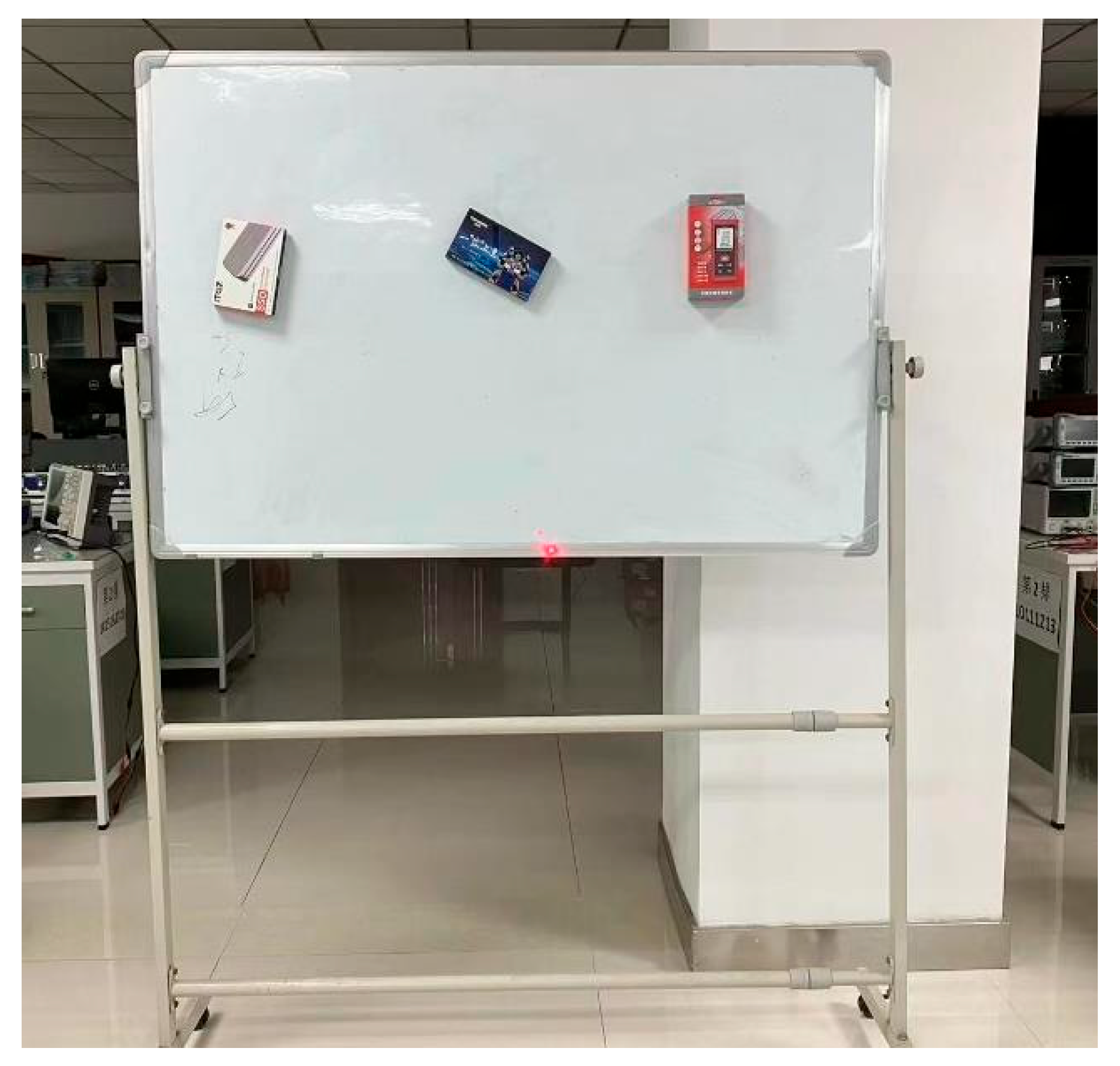
To initially verify the feasibility of the algorithm, a test field was set up in an indoor environment, as shown in
Figure 14. An adjustable-tilt whiteboard was used to simulate one side of the tunnel wall. By adjusting the distance between the whiteboard and the opposite wall, different encroachment scenarios in the tunnel can be simulated. The whiteboard position is fixed, and the LiDAR placement is adjusted to test the measurement accuracy at different data collection points. Additionally, known-sized cubes were randomly fixed on the whiteboard to simulate protrusion defects on the wall.
1. Encroachment Measurement
The distance between the LiDAR and the whiteboard was adjusted, and multiple measurements were taken to obtain the encroachment measurement results, which were recorded in the table. In the test, the whiteboard position was first fixed, and the measurement points of the LiDAR were changed to obtain multiple sets of data on the distance between the whiteboard and the wall. Then, the position of the LiDAR was kept unchanged, and the position of the whiteboard was adjusted, followed by re-measuring the distance. These measurements were compared with the true values obtained by the laser distance meter to calculate the error. Data analysis showed that when the whiteboard position was fixed, the absolute measurement error did not exceed 0.009 m. When the distance between the whiteboard and the wall was changed, the absolute error remained within 0.01 m, meeting the error requirements for construction sites.
2. Tilt Angle Measurement
Two positions were selected to install the LiDAR, and the tilt angle of the whiteboard was manually adjusted within a range from 0° to 30°. Multiple sets of data were measured, and the results were recorded in the table. The results showed that, at different relative distances, the absolute error of the tilt angle measurement did not exceed 1°, which meets the requirements for practical engineering applications.
3. Defect Localization
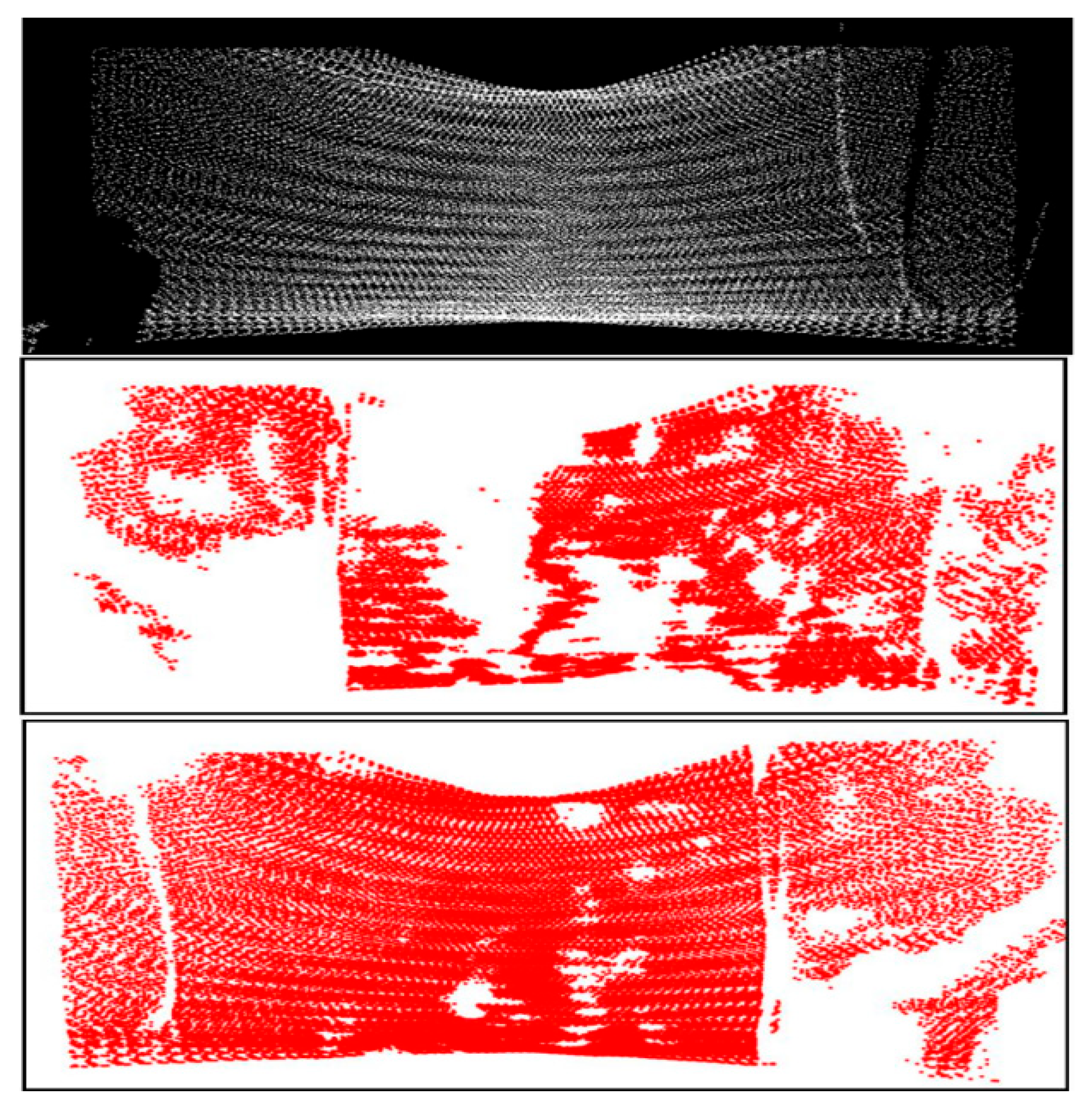
To validate the defect localization algorithm, the size of the simulated protrusion was first determined, followed by measurement of the relative position of the protrusion. A plane Cartesian coordinate system was established with the midpoint of the bottom edge of the whiteboard as the coordinate origin. After running the defect localization algorithm, the coordinates of the protruding object were obtained, as shown in
Figure 15. Compared with the measured values, the position error of the simulated protrusion did not exceed 1 cm, and the size error was less than 10%, which meets the requirements for engineering applications.
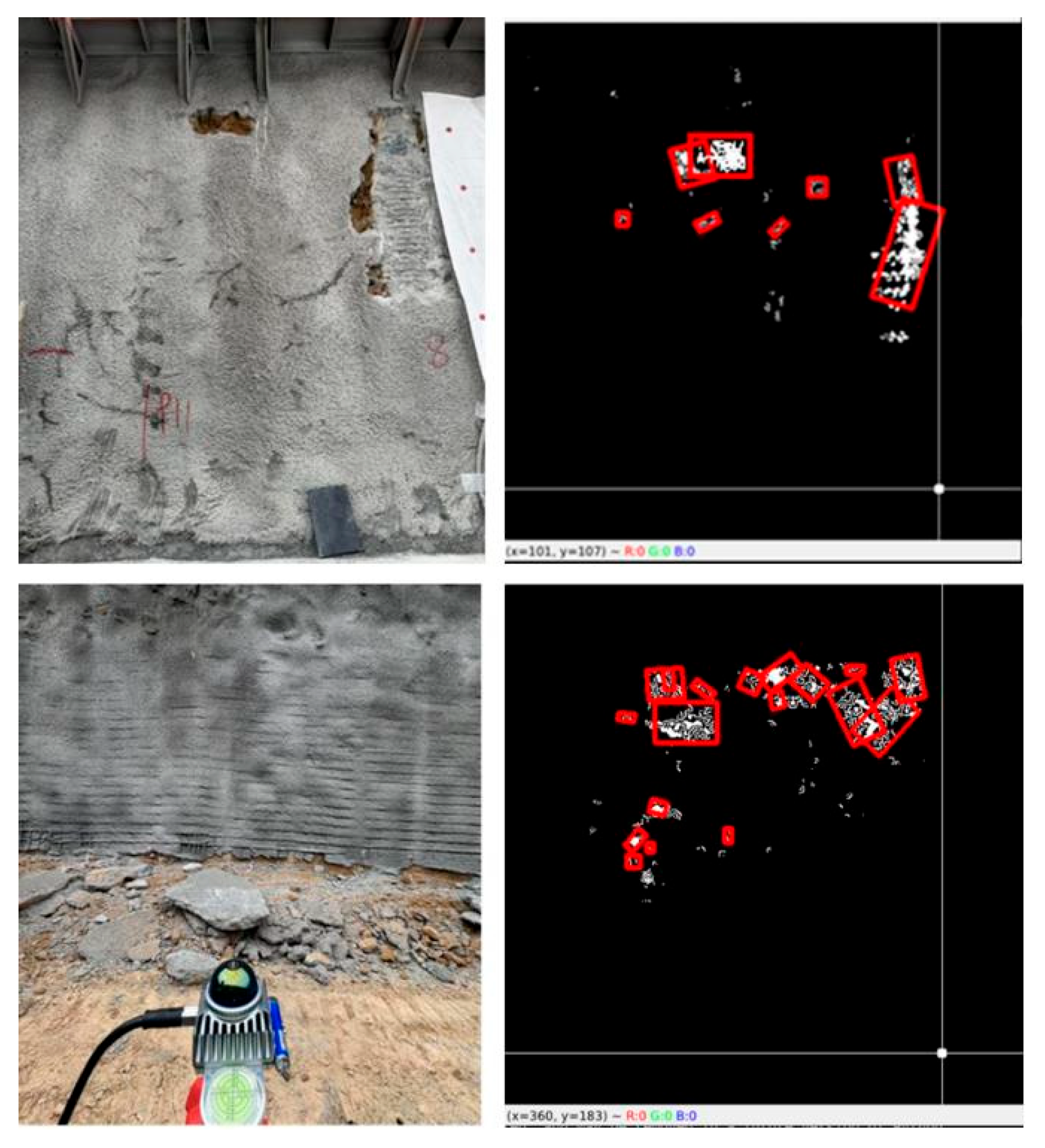
During the on-site system testing, an experiment was set up in the outdoor environment of a tunnel construction site, as shown in
Figure 16. The LiDAR device was mounted on a tripod and placed at the center of the tunnel to collect point cloud data from the support surfaces on both sides of the tunnel. A total of 7 measurement points were selected, and corresponding values for encroachment, tilt angle, and flatness were recorded. By comparing the measurement results with the standard data from the construction team, the accuracy of the method used in this study was verified to meet the requirements for construction measurement.
The results of the support surface defect localization are shown in the figure below.
4.2. Transformation Technology of Rebar System
In this study, aiming at the sagging deformation of rebar reinforcement skeletons in large-section tunnel construction (with a measured maximum deflection of 42 mm), innovative solutions are proposed: (1) establishing a mechanical analysis model for the construction process and a zonal suspension theory; (2) developing an intelligent suspension system for real-time monitoring of rebar reinforcement deformation; and (3) creating dual-control indices and a digital twin platform to achieve precise control. Comparative tests (involving single-point support and combined support schemes) were conducted to measure the changes in rebar displacement during different suspension stages. Application results indicate that this technology significantly improves construction quality and efficiency.
Engineering applications show that this technical system has increased the qualification rate of formwork trolley positioning, improved the qualification rate of concrete cover thickness, enhanced construction efficiency, and shortened the age difference between lining and invert. It has thus formed a complete set of intelligent construction technology solutions for long-span tunnels.
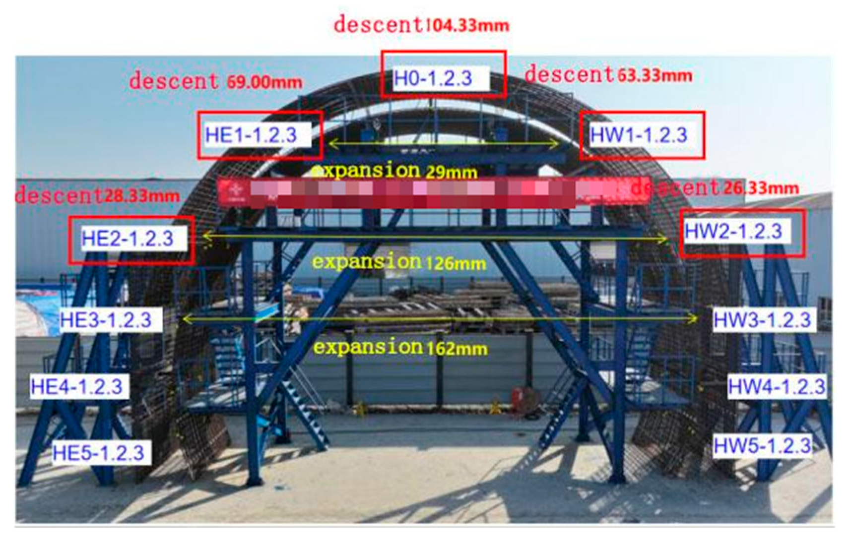
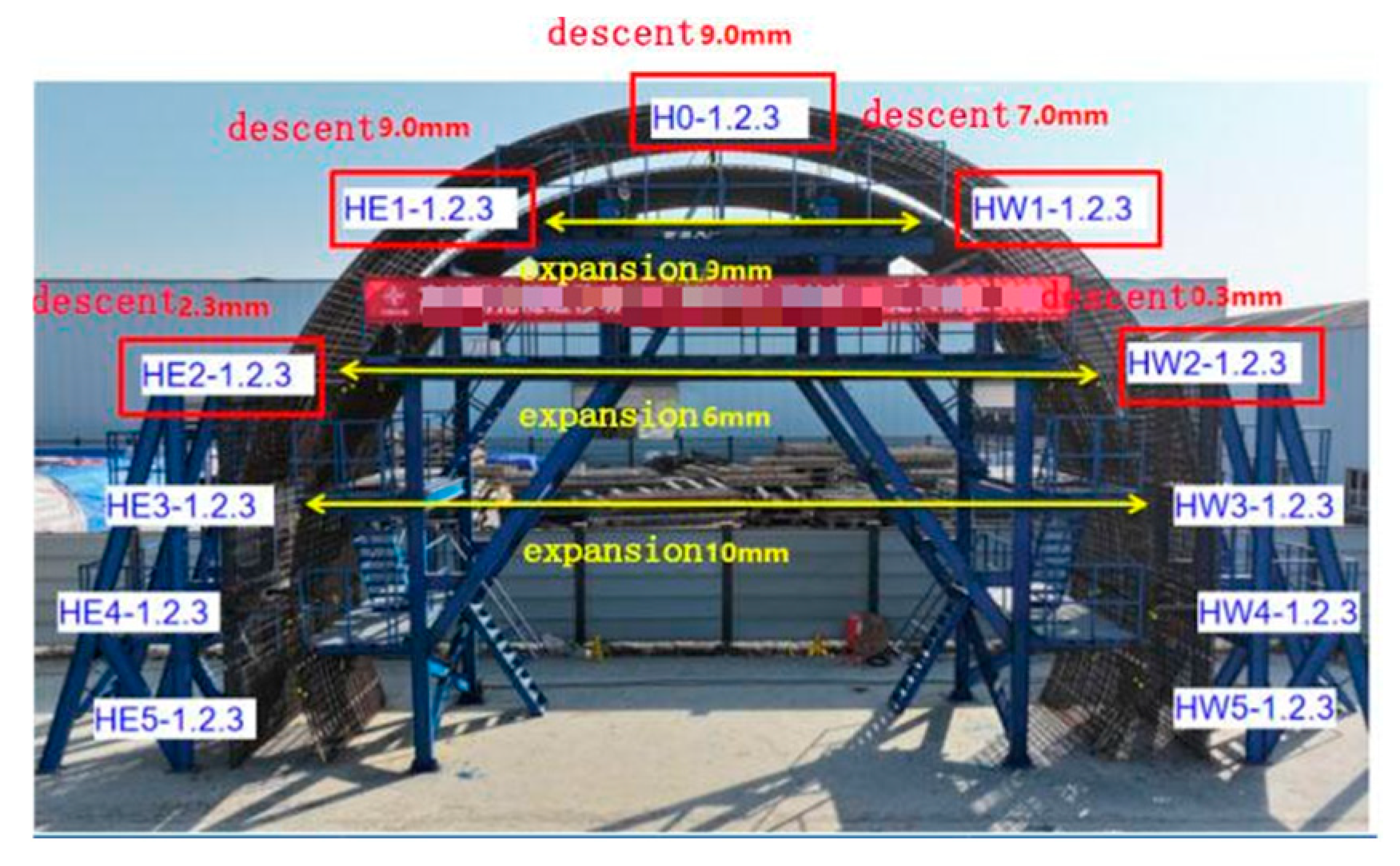
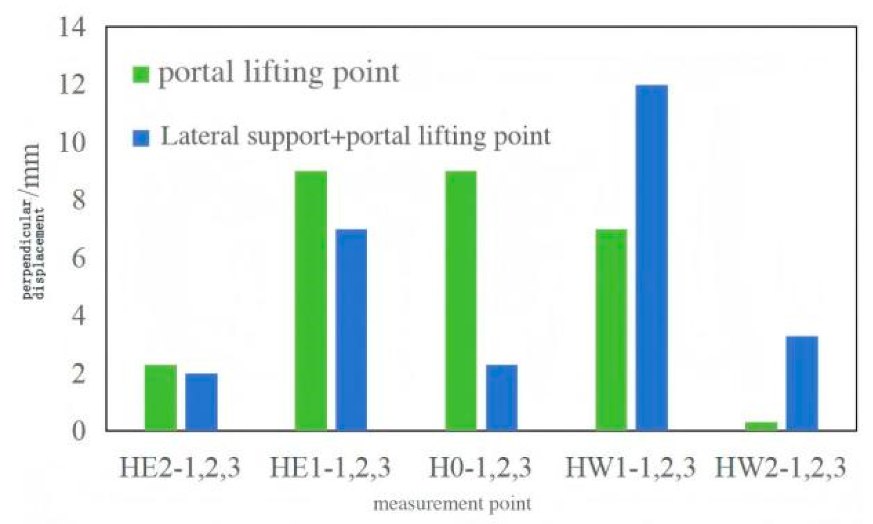
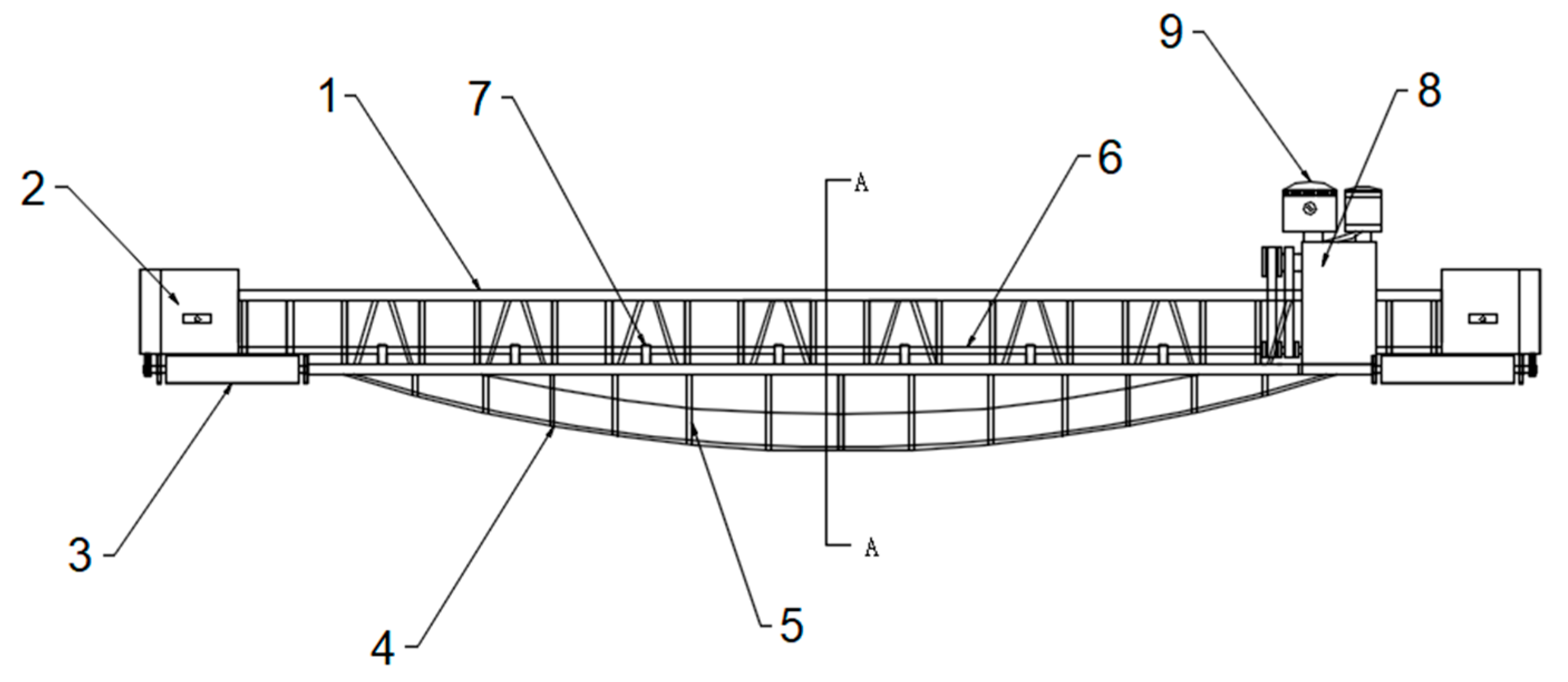
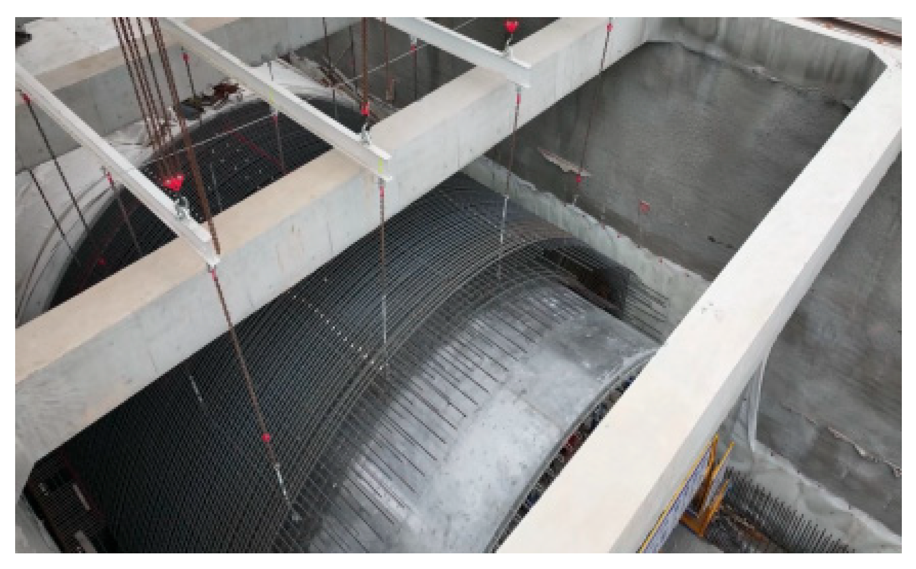
Field full-scale model tests (
Figure 17 and
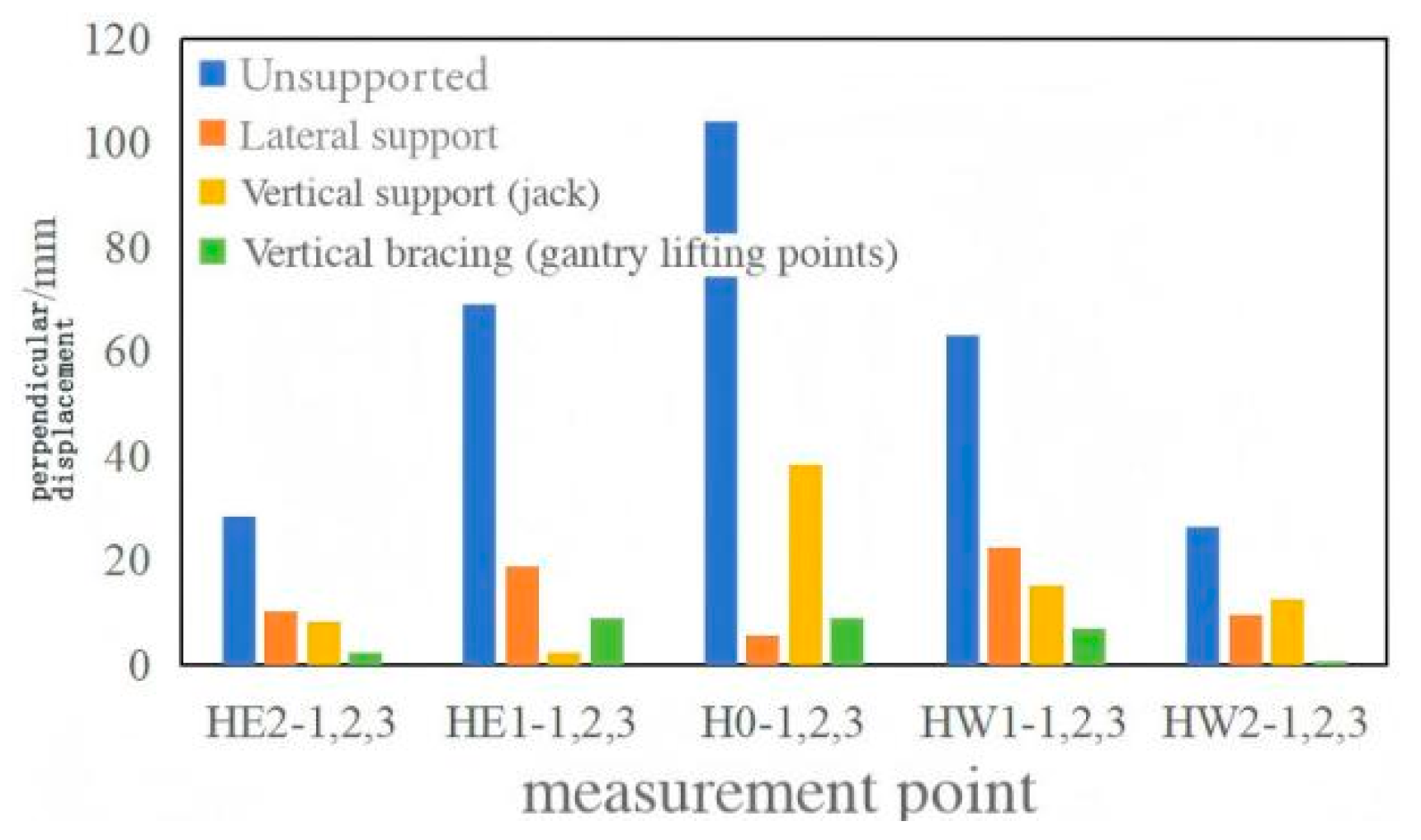
Figure 18) were carried out to compare two schemes: vertical and horizontal single-point supports (including horizontal supports, jacks, and gantry lifting points) and combined supports (horizontal supports + gantry lifting points, horizontal supports + jacks). Measurement points for the displacement of the reinforcement skeleton were designed (
Figure 19), and the displacement of each measurement point was recorded before, during, and after lifting. The displacement magnitudes of the two schemes were compared to select the optimal one (
Figure 20).
Given that the single-point support scheme is more straightforward to operate than the combined support scheme, it was decided to adopt the portal lifting point support scheme for the conversion of the lining reinforcement system.
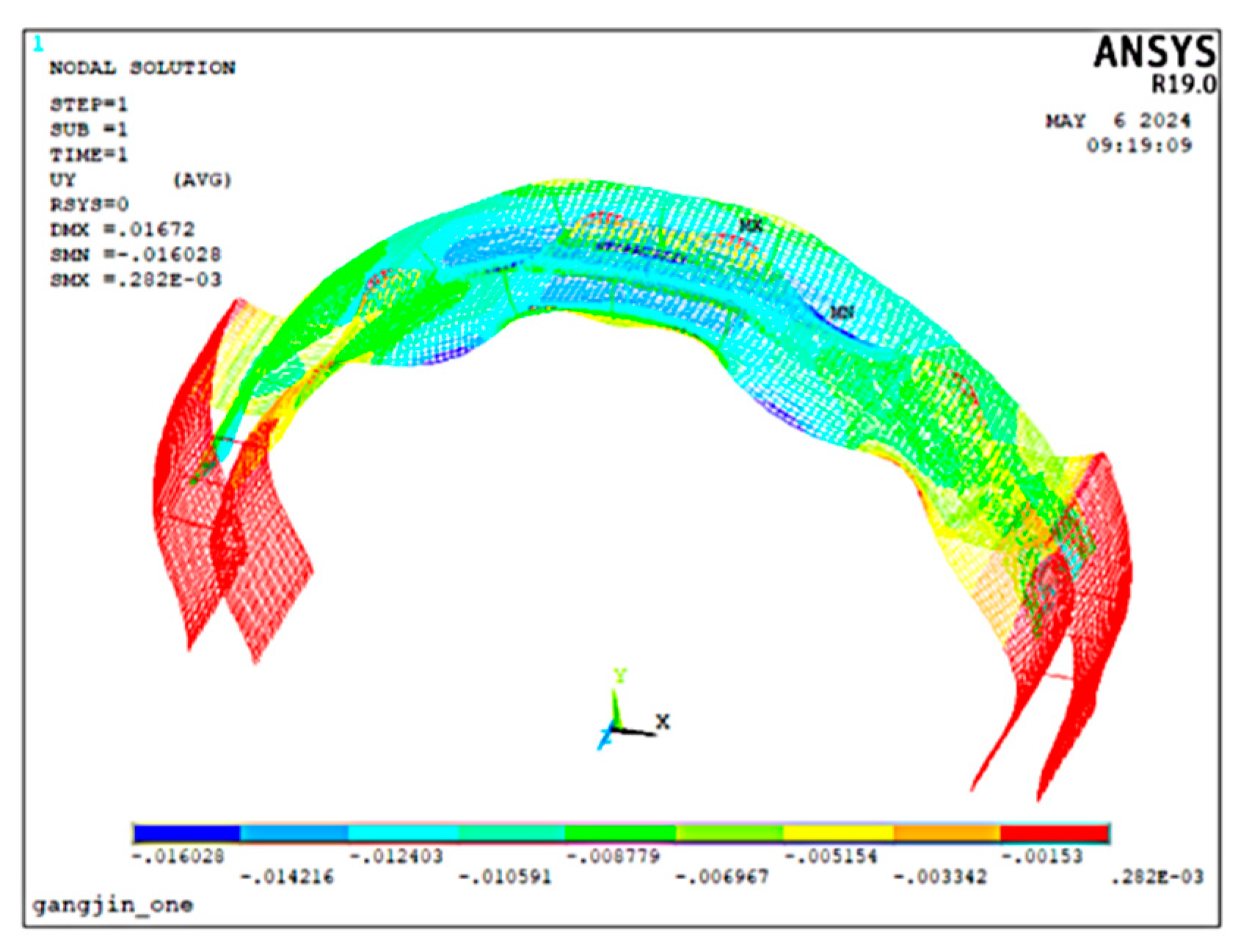
Following the selection of the lifting method, a numerical simulation model was established for in-depth analysis (
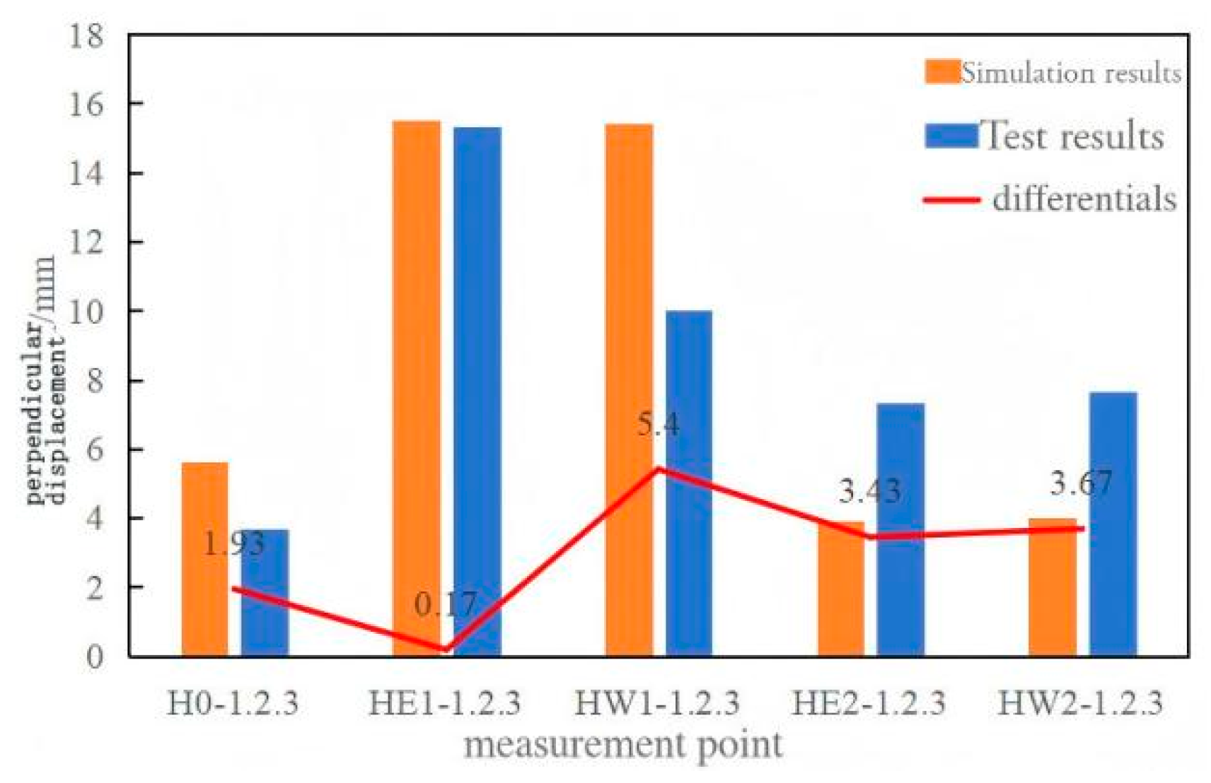
Figure 21). The results derived from this model were compared with those from the full-scale model test (
Figure 22) to verify the accuracy of the numerical model.
To assess the construction performance of the support scheme in a 9 m standard-section reinforcement cage, numerical analyses were performed based on model tests to provide guidance for field implementation.
The connection behavior between hoop and longitudinal bars in the inner mesh was analyzed to study the simulation of wire-tying. Two connection types were considered: hinged and rigid. Under gravity, the maximum vertical and horizontal deformations were 226 mm and 153 mm, respectively. Numerical simulations were performed using ANSYS R19.0.
The longitudinal bars contribute little to the stiffness of the hoop mesh, acting mainly as additional loads on the hoop bars. Hence, as long as their self-weight is effectively transferred through the joints, the overall structural performance is minimally influenced by the connection type.
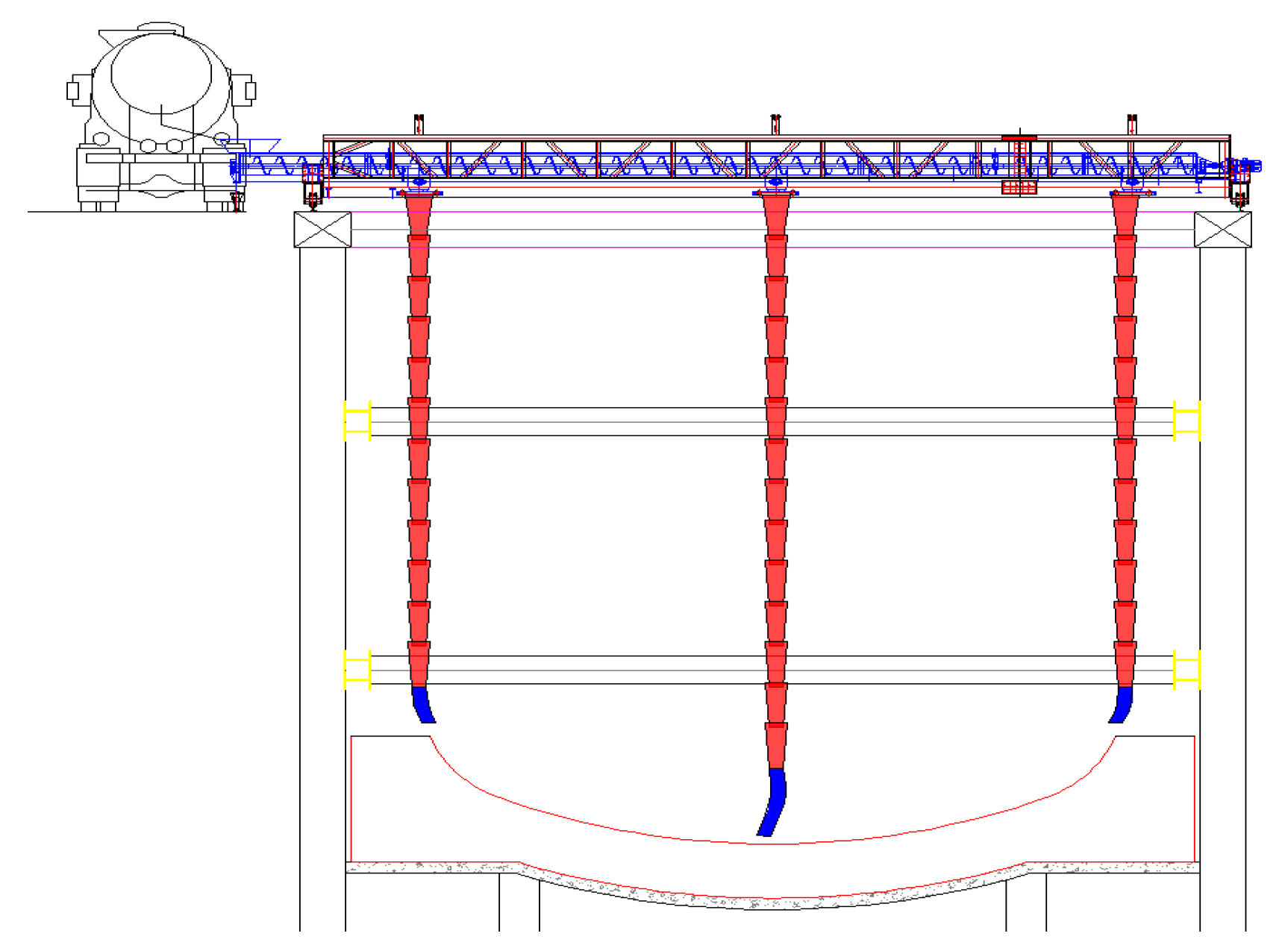
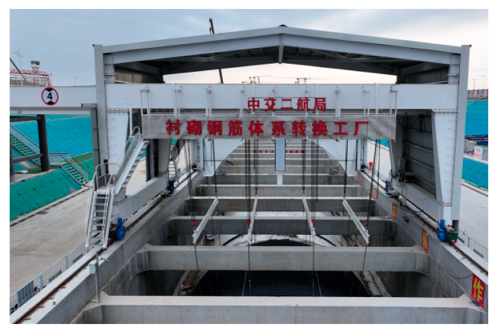
Based on the simulation results, 16 lifting points are arranged for the rebars in the 9 m standard section, divided into 4 rows with 4 points each. By utilizing factory premises and measurement-equipped distributed spreaders, and according to the load-bearing status of the rebar trolley, electric lifting devices are employed to achieve load-difference-free system conversion and control rebar deformation. With a designed deformation of 2 cm for the lining rebars, the application of this system conversion technology has resulted in a measured average deformation of only 5 mm and a maximum deformation of 10 mm, effectively ensuring the protective layer thickness and installation quality of embedded components.
Practical condition simulation:
In this section, the numerical model is designed to closely replicate the actual construction conditions. The side wall reinforcement is not connected to the on-site reinforcement, the lifting point positions are consistent with those used in the field, and no constraints are applied to the front and rear sides of the reinforcement mesh. The arrangement of lifting points is also aligned with the configuration adopted in on-site construction. The analysis primarily investigates the total tensile force required under two scenarios: without applying forces at the lifting points and with lifting point forces applied.
The actual spacing of the erected reinforcement bars is 1.2 m, expressed as 0.3 m + 1.2 m × 7 + 0.3 m. The lifting points are arranged at intervals of 2.4 m + 3.6 m + 2.4 m, resulting in a total of 16 lifting points distributed across four rows.
Case 1: Lifting points without applied force
When no lifting force is applied at the lifting points (with the y-direction displacement of the fixed lifting points remaining unchanged), the inner reinforcement mesh exhibits a downward deformation of 16 mm, an upward deformation of 1.1 mm, and a maximum lateral deformation of 18 mm. The corresponding calculation results are illustrated in
Figure 23.
The total tensile force required by the 16 lifting points is 29.3 t, compared to the total reinforcement mesh weight of 53.9 t, yielding a load-sharing ratio of 54%.
Case 2: Lifting points with applied force
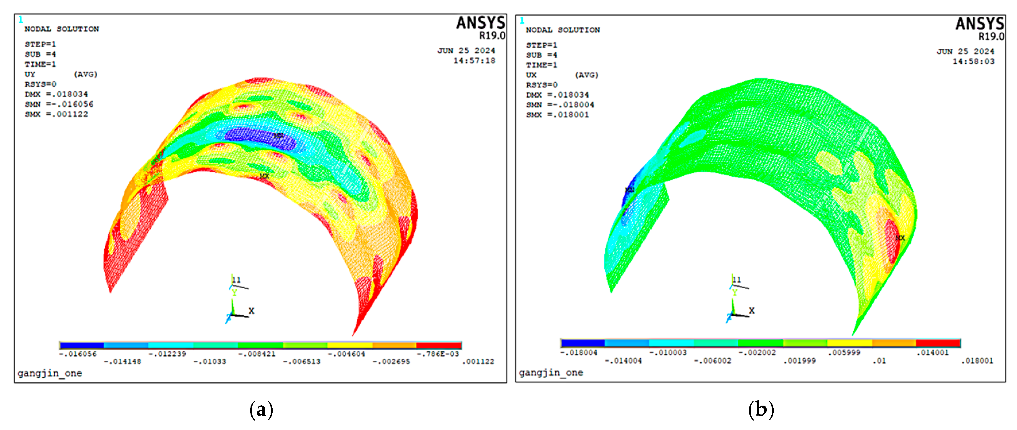
In the numerical simulation, the method of applying force at the lifting points differs from the actual construction practice. On-site, the lifting force is applied through I-beams, whereas in the numerical model, the force is applied directly as tensile forces on the 16 lifting points, aiming to adjust the deformation of the reinforcement mesh. After multiple adjustments and optimization, the resulting deformation contours are shown below (
Figure 24). When adjusted to the minimum deformation state, the inner reinforcement mesh exhibits a downward deformation of 7.2 mm, an upward deformation of 7.8 mm, and a maximum lateral deformation of 8.6 mm.
The total tensile force required for the 16 lifting points is 32.5 t, while the total weight of the reinforcement mesh is 53.9 t, resulting in a load-sharing ratio of 60.3%.
From the overall deformation of the reinforcement cage, the scheme with applied lifting point forces demonstrates better performance. The distribution characteristics of the lifting point forces are as follows: the edge rows carry more force than the middle rows, and the middle two rows carry more than the front and rear rows. The combined force of the 8 lifting points in the middle two rows accounts for approximately 70% of the total.
Application in the field:
Using the workshop and distributed lifting devices with measurement capabilities, and based on the load state of the rebar trolleys, an electric hoisting system was employed to achieve a no-load differential transfer, controlling reinforcement deformation. The lining reinforcement was designed for 20 mm deformation, while the measured average deformation was 5 mm, with a maximum of 10 mm, ensuring protective layer thickness and proper installation of embedded components.
4.3. Self-Sensing Maintenance Technology
Concrete curing methods are categorized into standard curing and natural curing. Standard curing involves curing concrete specimens in a standard curing room, with a temperature of (20 ± 2) °C and a relative humidity of ≥95% [
29]. Natural curing is conducted at room temperature (with an average temperature of not less than 5 °C), where watering or water retention methods are used to maintain appropriate temperature and humidity conditions for concrete hardening within a specified period [
30].
If concrete is not moisturized and cured in a timely manner after pouring, cement particles cannot fully hydrate and transform into stable crystals, which is prone to causing significant shrinkage deformation and the occurrence of dry shrinkage cracks, thereby compromising structural durability. Based on the requirements of relevant specifications and the successful experience of curing test blocks in laboratories, it is determined that a concrete surface humidity of ≥95% shall serve as the moisturizing standard for curing in natural environments, and a mathematical model for concrete moisturizing and curing has been established [
31].
The factors affecting the quality of ready-mixed concrete are highly complex (
Figure 25), including raw material quality, production process parameters, environmental conditions, and technical objectives, among others. The concrete production process is influenced by multiple objectives, levels, and factors. The combination of these factors can generate an infinite number of variables, making it impossible to efficiently and rationally regulate these changes relying solely on human capabilities [
32].
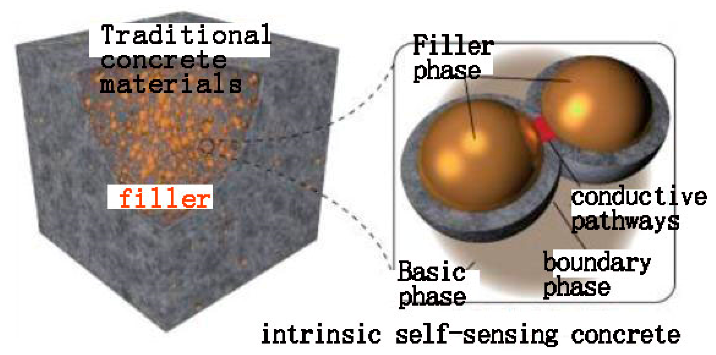
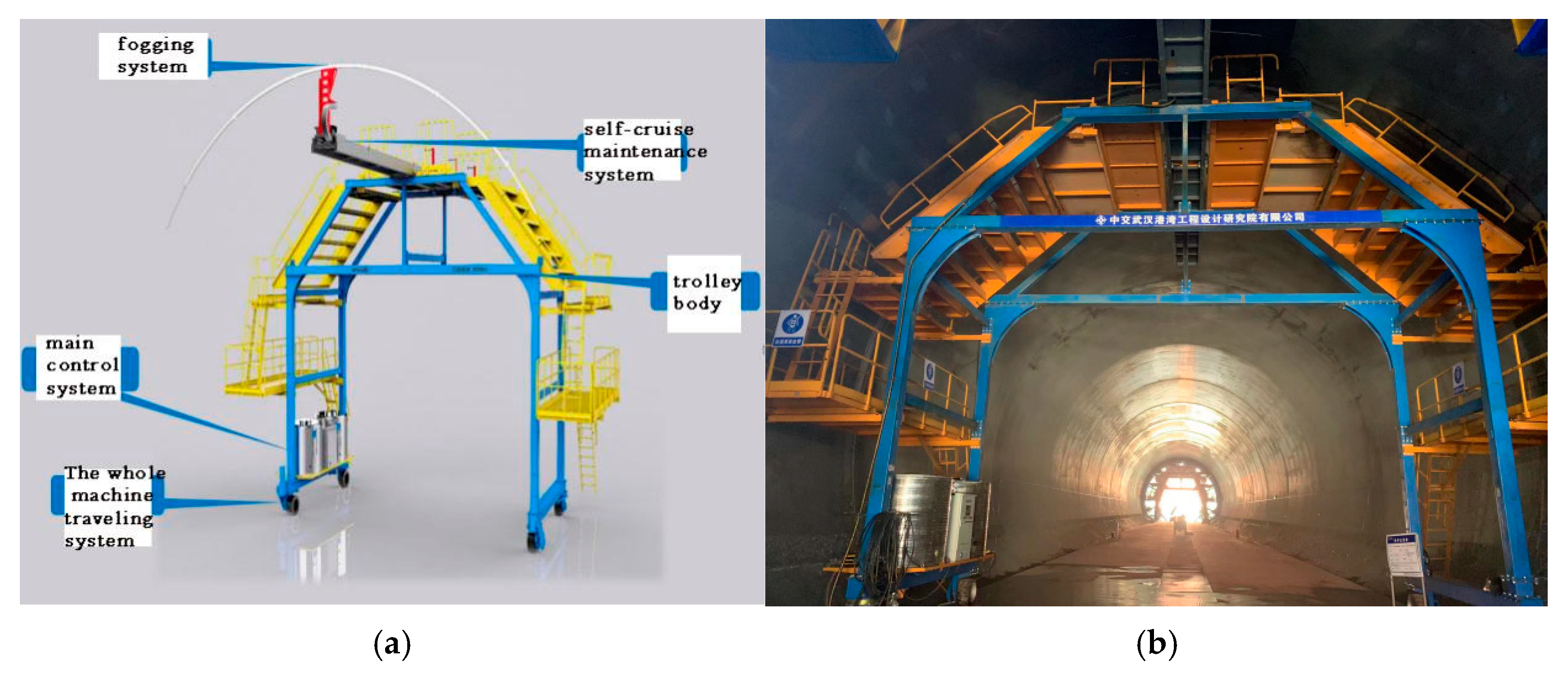
Concrete self-sensing maintenance technology consists of two components: self-sensing technology and adaptive maintenance technology. Among them, concrete self-sensing technology is an advanced technical means, mainly realized through embedding various sensors in concrete structures. Currently, intelligent sensing technologies applied in concrete structures include fiber optic sensors, fiber Bragg grating sensors, and piezoelectric sensors, etc. These sensors are usually embedded in concrete for structural health monitoring and exhibit excellent sensing performance [
33,
34]. Alternatively, it can be achieved by utilizing certain physical properties of concrete itself (e.g., changes in electrical conductivity; the concrete matrix itself is not self-sensing, but this capability can be significantly enhanced by incorporating functional fillers, which enable the concrete to monitor deformations under external loads and convert them into electrical signals [
35]). These sensors can monitor and record key parameters such as internal stress, temperature, and humidity in real time, as well as detect external changes in the concrete state such as deformation and cracks. When there is any change in the internal or external state of the concrete, these sensors will quickly convert such changes into electrical or other recognizable signals, thereby realizing real-time monitoring and assessment of the concrete state (
Figure 26).
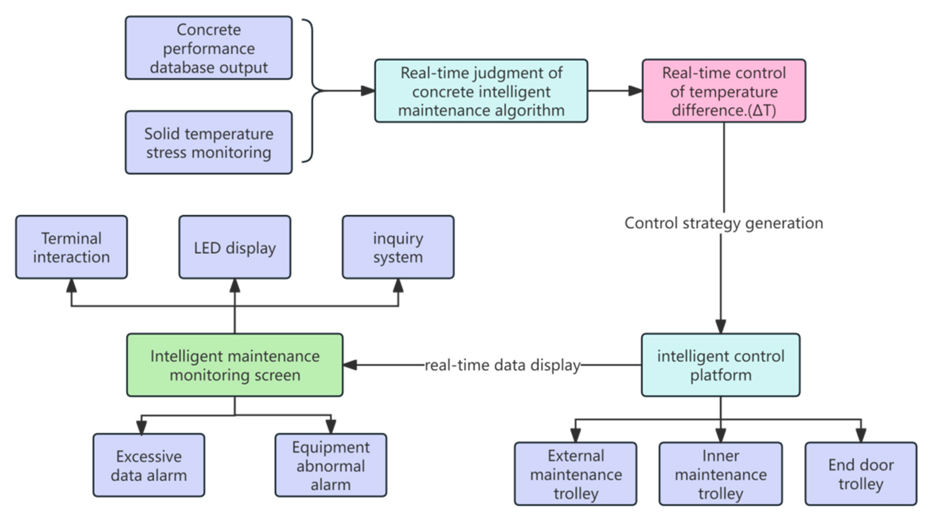
Concrete self-sensing adaptive (
Figure 27) maintenance hardware and software components mainly consists of sensor acquisition unit, intelligent control platform, monitoring screen and maintenance equipment and other components, of which the sensor acquisition unit includes temperature, humidity and strain acquisition unit. Through algorithm loading, input parameter design, model building, sensor data acquisition, and using machine learning, deep learning algorithms [
36] to optimize the control strategy in order to improve the control effect.
The hardware and software components of the concrete self-sensing adaptive curing system mainly include a sensor acquisition unit, an intelligent control platform, a large monitoring screen, and curing equipment, with the sensor acquisition unit comprising temperature, humidity, and strain acquisition modules. For algorithm loading, based on the properties of concrete and curing requirements, the intelligent curing algorithm calculates real-time control targets, dynamically analyzing the interaction mechanism among temperature, humidity, and stress fields through thermodynamic conduction equations and hydration reaction kinetics algorithms; combined with a database of material characteristic parameters such as layered pouring intervals, shrinkage and creep coefficients, and hydration heat release curves, feature engineering methods are applied to perform dimensionality reduction and correlation analysis on mix proportion parameters (e.g., stress range, temperature range, humidity range). Input parameter design involves entering, in line with algorithm requirements, design parameters including the interval between upper and lower concrete layers, mix proportion shrinkage, mix proportion adiabatic temperature rise, and concrete elastic modulus. A mathematical model for predicting concrete conditions is built based on the physical properties of concrete and historical data, while real-time data on the internal state of concrete is collected through a sensor network, with the collected data undergoing cleaning, filtering, and denoising to enhance accuracy and reliability. Machine learning and deep learning algorithms are used to optimize control strategies for better control effects, and in the field of concrete, deep learning algorithms are mainly applied to aspects like surface quality, strength, and mesomechanical behavior. Adaptive control strategies are converted into specific control instructions, which are then transmitted to executive devices such as water sprayers, heating units, and humidity regulators to adjust the concrete state; the adaptive control strategies are adjusted and optimized based on feedback data to adapt to changes in concrete conditions, and meanwhile, real-time monitoring data is compared with preset thresholds or standards to detect abnormalities.
By monitoring the concrete condition in real time and combining it with precise curing measures, the safety and stability of concrete structures can be significantly enhanced. This not only ensures the long-term reliability of the structure but also effectively extends its service life, resulting in a more robust building.
Test analysis:
1. Monitoring System Layout
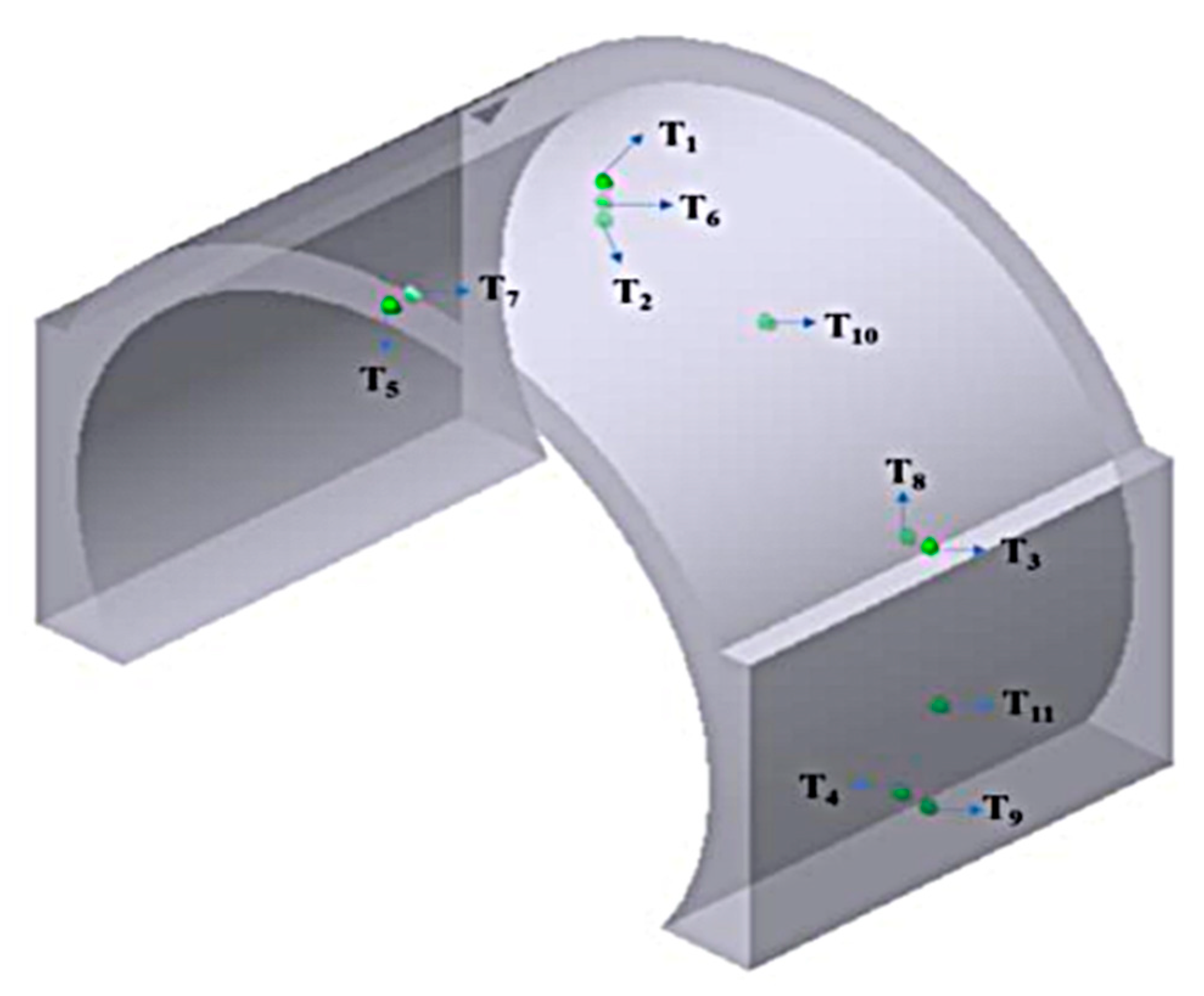
Temperature sensors were embedded in both the interior and surface of the secondary lining concrete of the tunnel according to the arrangement shown in the figure below. These sensors enable real-time monitoring of the concrete temperature during casting, including the initial molding temperature, the core and surface temperatures during the hydration heat release stage, providing a basis for adjusting parameters such as curing temperature, duration, and interval of the curing trolley. Data on the peak temperature, temperature rise, and internal-to-surface temperature difference in the secondary lining concrete were collected to analyze the curing quality. Humidity sensors were uniformly distributed within the tunnel to monitor the curing humidity (
Figure 28).
2. Curing Humidity Test
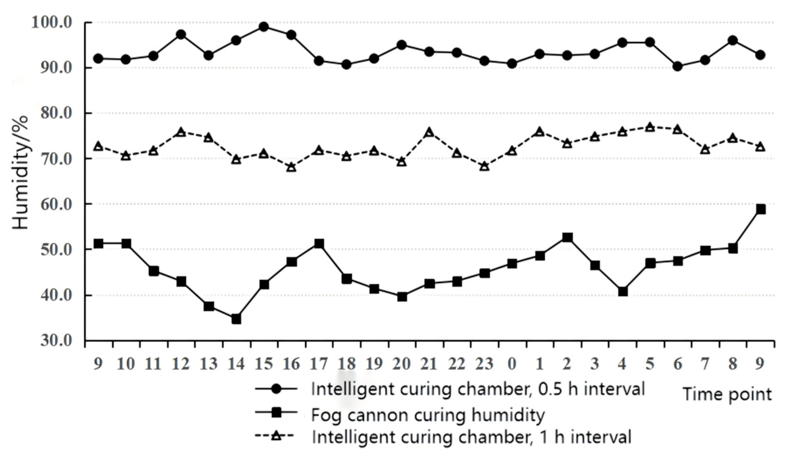
Three curing methods were applied to study the humidity conditions inside the tunnel: fog cannon spray curing, and intelligent curing chamber curing with intervals of 0.5 h and 1 h, respectively, with the fog cannon spray interval set at 0.5 h. According to the humidity curves, during fog cannon spray curing, the tunnel humidity fluctuated between 34.8% and 58.9%. For the intelligent curing chamber with a 0.5 h interval, the curing humidity remained between 90.2% and 98.9%, with minimal variation. With a 1 h interval, the intelligent curing chamber maintained humidity between 68.1% and 76.9%, showing small fluctuations. Compared with fog cannon spray curing, the intelligent curing chamber provides stable and higher humidity for the secondary lining concrete, with the 0.5 h interval yielding the best humidity performance (
Figure 29).
3. Curing Temperature Test
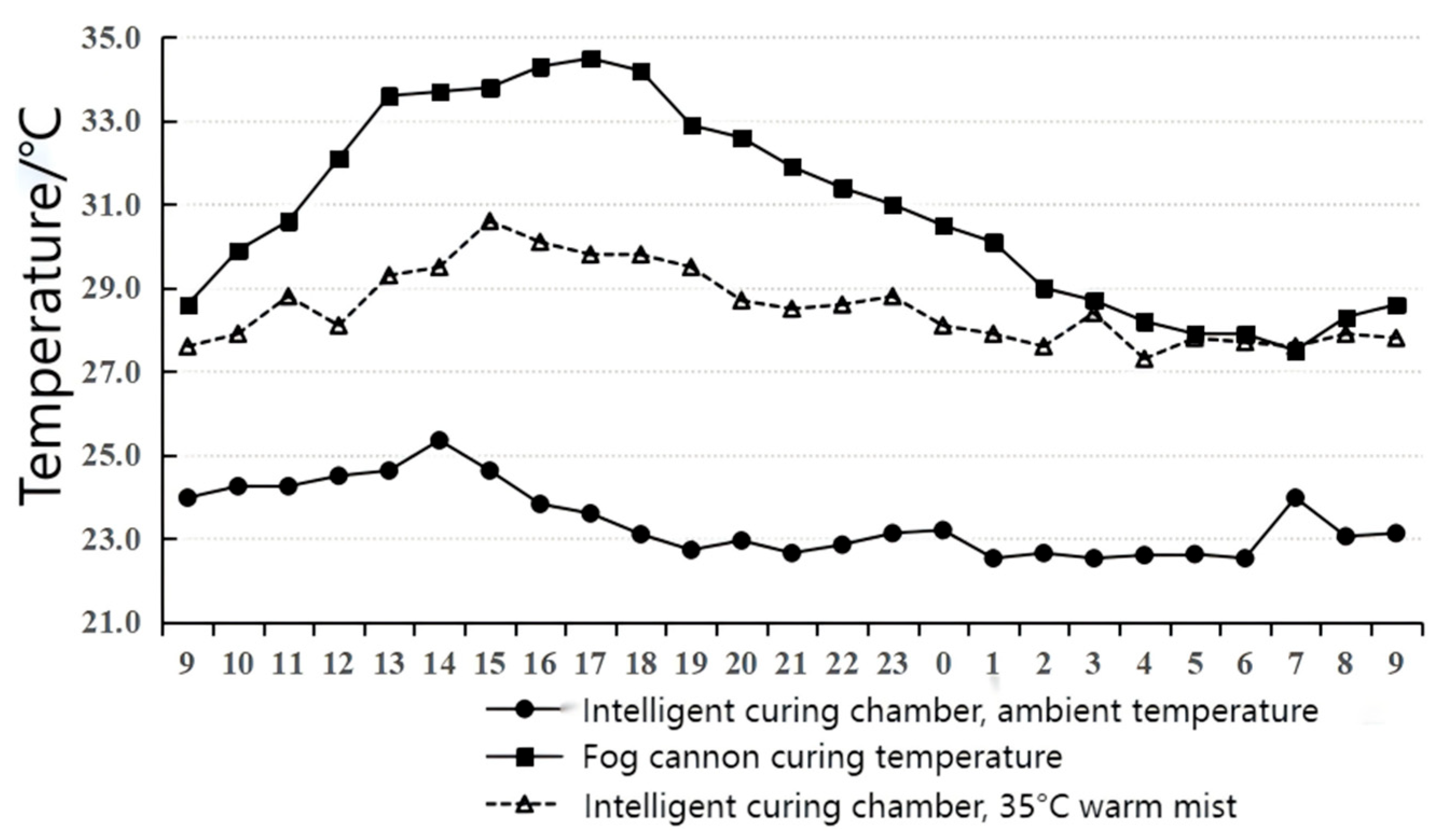
Three curing methods were applied to study the temperature conditions inside the tunnel: fog cannon spray curing, intelligent curing chamber curing at ambient temperature, and intelligent curing chamber curing with 35 °C warm mist, all with a 0.5 h interval. According to the curing temperature curves, during fog cannon spray curing, the tunnel temperature ranged from 27.5 °C to 34.5 °C, exceeding 32 °C between 12:00 and 20:00. For ambient temperature curing, the intelligent curing chamber maintained a temperature range of 22.5 °C to 25.4 °C. For 35 °C warm mist curing, the intelligent curing chamber temperature ranged from 27.3 °C to 30.1 °C (
Figure 30).
4. Internal-to-Surface Temperature Difference Test
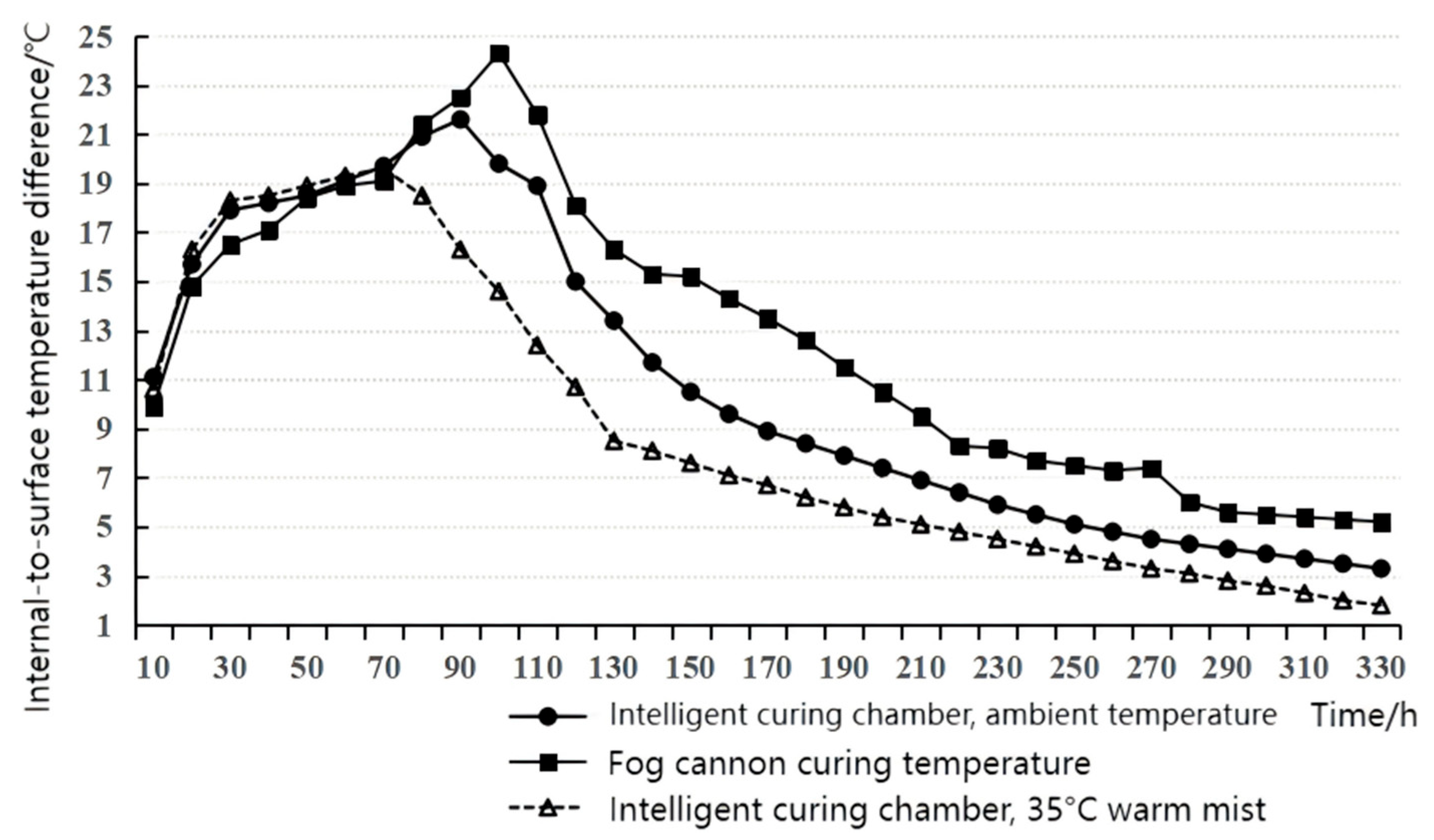
The internal-to-surface temperature differences in the secondary lining concrete in the tunnel were collected under three curing methods: fog cannon curing, intelligent curing chamber at ambient temperature, and intelligent curing chamber with 35 °C warm mist, as shown in the figure below. The curing interval was 0.5 h for all cases, with a total curing period of 14 days. During the first 72 h, curing was performed with formwork in place. As the concrete hydration progressed, the core temperature increased rapidly, and the internal-to-surface temperature difference gradually grew. After the fog cannon curing began, the internal-to-surface temperature difference first increased and then decreased, reaching a maximum of 24.3 °C, exceeding the project’s temperature control standard of no more than 20 °C. With ambient temperature water curing in the intelligent curing chamber, the maximum internal-to-surface temperature difference was 21.6 °C, decreasing to below 10 °C after 150 h. Using 35 °C warm mist curing in the intelligent curing chamber, the internal-to-surface temperature difference gradually decreased, reaching below 10 °C after 48 h of curing (
Figure 31).
5. Concrete Strength Test
According to JGJ/T·23-2011 [
37], a rebound hammer was used to measure the in situ compressive strength of secondary lining concrete at different ages under various curing methods. The collected concrete strength data are presented in
Table 1 below.
From the above table, it can be seen that the 3-day compressive strength of the secondary lining concrete cured in the intelligent curing chamber with ambient-temperature water is nearly 10% higher than that cured with the fog cannon. The 3-day strength of concrete cured with 35 °C warm mist in the intelligent curing chamber is 13.2% higher than that of fog cannon curing, and the 7-day strength is 9.9% higher. After 14 days, the compressive strengths of all three methods are similar. Moreover, during rebound testing, the early strength results of concrete cured with the fog cannon showed relatively large dispersion, which was attributed to uneven concrete hydration. In contrast, the early strength of concrete cured in the intelligent curing chamber, under both temperature modes, was relatively uniform.
6. Summary of Results
Using the intelligent curing chamber with a 0.5 h curing interval can provide a curing environment with humidity ≥90%. Under ambient-temperature curing, the chamber temperature ranged from 22.5 °C to 25.4 °C; under 35 °C warm mist curing, the temperature ranged from 27.3 °C to 30.1 °C.
With a 0.5 h curing interval and 35 °C warm mist in the intelligent curing chamber, the maximum internal-to-surface temperature difference in the tunnel secondary lining concrete can be controlled to ≤20 °C, the 3-day compressive strength can be increased by 13.2%, and the 7-day compressive strength can be increased by 9.9%.
4.4. Equipment Cluster Remote Control Technology
Aiming at the problems of low manual operation efficiency, high communication costs, and insufficient intelligence in traditional open-cut tunnel construction, a collaborative operation model for mobile factory equipment is constructed based on key data. This model enables subdivided storage and accurate calling of equipment action instructions for trolleys, vibration rods, and other devices. By integrating BIM technology and digital twin technology, an intelligent cluster control system for open-cut tunnel equipment is developed to realize remote control, intelligent scheduling, and real-time monitoring of equipment.
Through the use of high-speed mobile Internet, Programmable Logic Controller (PLC) equipment [
38,
39,
40,
41], and Data Transfer Unit (DTU) communication, cluster control of on-site trolleys, vibration equipment, and maintenance equipment is achieved. Additionally, two sets of software are developed: the intelligent monitoring system and the intelligent trolley control system for mobile factory equipment in open-cut tunnels.
A DTU is a wireless terminal device specifically designed to convert serial data into IP data or IP data into serial data for transmission via wireless communication networks. In essence, the connection established between a DTU and a data processing center is a SOCKET connection, where the DTU acts as the SOCKET client and the data processing center functions as the SOCKET server. SOCKET connections can use either the Transmission Control Protocol (TCP) or the User Datagram Protocol (UDP) [
42], with the DTU and the center required to use the same protocol, typically configured via configuration software. After configuring the DTU with the center’s IP address and port number, the DTU is connected to the user’s equipment through a serial port. When powered on, the DTU first registers with the mobile network, then sends a SOCKET connection request packet to the mobile network, which forwards this request to the Internet [
43].
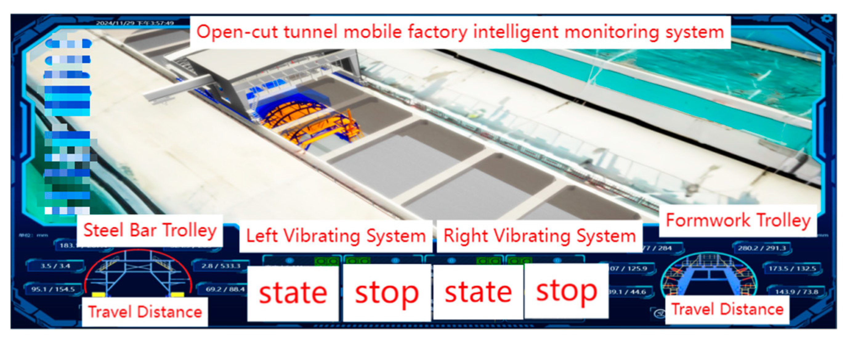
The control system of the mobile factory collaborative control digital platform is built on a digital model library. It collects key data in three aspects—equipment, environment, and quality—in real time during the construction process. Users can log into the system via the Internet to check relevant construction data at any time, breaking spatial barriers to achieve remote monitoring of on-site equipment. Meanwhile, through high-speed mobile Internet, PLC equipment, and DTU communication, cluster control of on-site trolleys, vibration equipment, and maintenance equipment is realized. Two sets of software have been developed: the intelligent monitoring system for mobile factory equipment in open-cut tunnels and the intelligent trolley control system (
Figure 32).
Among them, the intelligent monitoring system includes: a rebar trolley monitoring system (
Figure 33A), a formwork trolley monitoring system, a vibration monitoring system (
Figure 33B), and a maintenance trolley monitoring system. The intelligent trolley control system includes: a rebar trolley control system (
Figure 33C), a formwork trolley control system, a vibration control system (
Figure 33D), and a maintenance trolley control system.
6. Digital Twin of Open-Cut Tunnel
Research on the whole-process control model of open-cut tunnels based on digital twins aims to realize multi-parameter and multi-modulus refined construction management in a 3D virtual construction scenario. It sorts out the overlapping and crossing operations throughout the whole process of open-cut tunnel construction and builds a 3D BIM model (
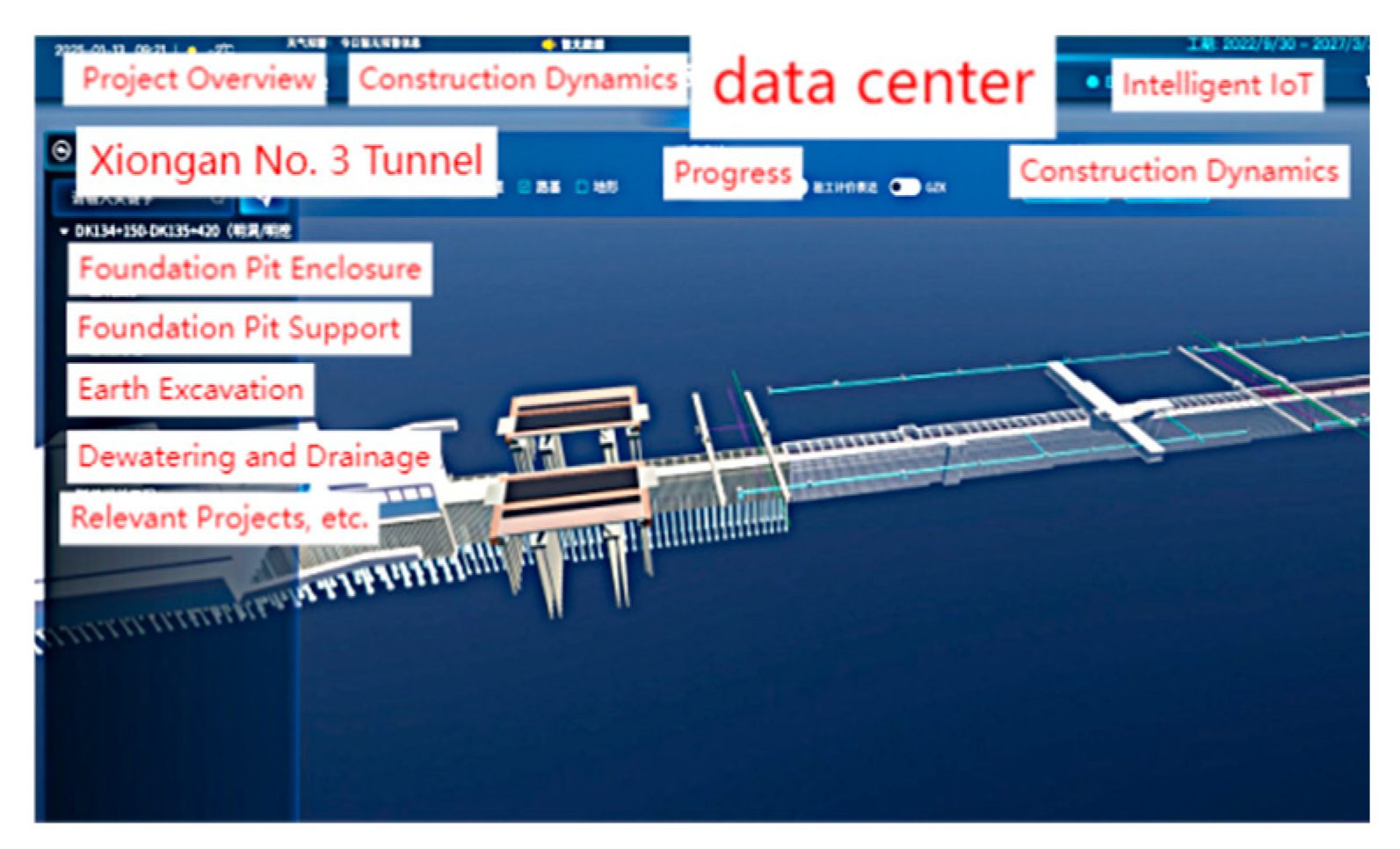
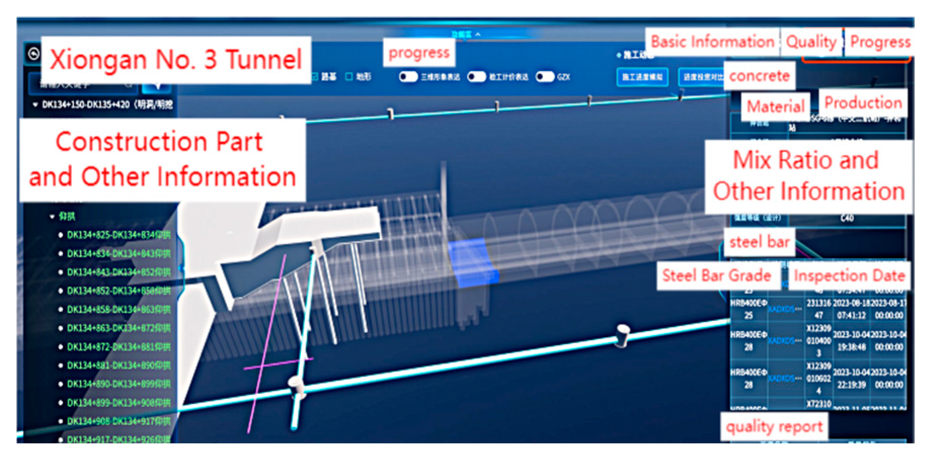
Figure 49) for each process. Based on the BIM model for the whole-process construction, an interactive display interface is developed to show the virtual simulation construction status in real time after user operation. It comprehensively monitors (
Figure 50) and warns of the running status of equipment groups, construction progress, and monitoring data of process quality control indicators during tunnel construction, enabling dynamic control of on-site equipment operations only through remote clients, thus achieving refined management of equipment walking, opening and closing, and system conversion in construction.
The application of digital twin technology in open-cut tunnels is centered on “data-driven and virtual-real interaction”, with its technical framework usually consisting of four levels: physical layer, transmission layer, model layer, and application layer. The physical layer collects real-time data such as tunnel structure deformation, soil stress, and groundwater status through sensors (e.g., fiber Bragg gratings, inclinometers, and earth pressure cells); the transmission layer relies on 5G, Long Range Radio (LoRa), or Beidou communication technologies to achieve low-latency data transmission, with particular attention to optimizing signal coverage in deep foundation pits or underground enclosed environments; the model layer builds a high-precision 3D twin model based on BIM + GIS (Geographic Information System) integrated modeling, combining geological survey data and construction parameters, and integrates a finite element analysis (FEA) module to predict structural responses; the application layer realizes functions such as construction progress simulation, risk early warning, and remote command issuance through visual interfaces, while remote control technology focuses on the intelligent upgrading of construction equipment.
To optimize the process logic of key construction operations, this study addresses bottlenecks in multi-process coordination. A BIM-based process parameter database is established to digitally represent construction elements, while a process logic engine enables dynamic simulation of construction sequences and virtual rehearsal of potential conflicts. An intelligent decision-making closed loop—comprising process parameter optimization, equipment action coding, and on-site execution feedback—is implemented, forming a fully digitalized process chain for tunnel construction. By integrating modular technical clusters with a digital platform, the approach systematically enhances the standardization and intelligence of open-cut tunnel construction.
Economic Efficiency Comparison:
Intelligent construction techniques significantly shorten construction cycles and reduce labor costs through automated formwork movement, digital monitoring, and coordinated equipment operation (
Figure 51). For instance, the use of intelligent formwork systems reduces manual adjustments and repetitive labor, enabling continuous operation and a 20% reduction in construction time. Despite higher initial investments, the overall project cost can be reduced by approximately 10–20%.
Safety Comparison:
Intelligent construction technologies minimize workers’ exposure to hazardous environments through remote control and automated equipment. Real-time monitoring systems provide structural stability data, allowing timely detection of potential risks. Compared to conventional methods, the incidence of work-related accidents is significantly reduced. For example, the application of digital twin technology in tunnel construction enhances real-time monitoring and early warning, improving construction safety.
Incident Prevention Comparison:
Intelligent techniques enable continuous monitoring and predictive analysis, identifying anomalies such as ground settlement, concrete curing status, and structural integrity. Integrated early warning systems help detect abnormalities and prevent incidents like lining cracks, water ingress, or formwork displacement. Field applications have demonstrated a 50–80% reduction in lining defects and construction-related incidents compared to traditional construction methods.
6.1. The Construction of the Whole Process BIM Model
In the systematic combing of processes, the digital construction framework is constructed by decomposing three core modules: waterproof and cushion construction, inverted arch pouring, and lining structure forming. Based on digital twin technology, the whole-process construction of open-cut tunnels is modularized and reorganized, forming a systematic management system for intelligent construction processes at each stage of the “waterproof and cushion-invert-lining” sequence. Through the BIM model, traditional scattered processes are digitally analyzed, and a construction logic network for core processes is established.
6.2. Multi-Source Heterogeneous Database Construction and Dynamic Mapping of BIM Models
Aiming at the problem of multi-source data fusion in open-cut tunnel construction, a three-tier architecture solution is proposed: (1). Data access layer: A lightweight adapter uniformly accesses BIM data in different formats; (2). Semantic mapping layer: Component coding and attribute naming conflicts are solved based on knowledge graphs and rule bases; (3). Dynamic adaptation layer: A metadata-driven algorithm dynamically adapts to the requirements of the target model. Meanwhile, a three-dimensional fusion model of “structure-attribute-space-time” is proposed, which combines Level of Detail (LOD) classification, fuzzy logic evaluation, and spatiotemporal index technology to realize the accurate fusion of multi-source data such as BIM and oblique photography. In addition, through parametric modeling and hash algorithms, the dynamic mapping between the construction physical space and digital space is established to support the correlation analysis of component parameters with indicators such as progress and quality.
6.3. Construction Process Monitoring and Early Warning and Intelligent Diagnosis
A construction early warning system based on dynamic threshold optimization is proposed, which combines project characteristics, environmental variables, and historical data to set hierarchical warning intervals for progress, quality, and other aspects. It adopts a three-level threshold framework of “safe-dangerous-emergency” and realizes intelligent risk matching by using a knowledge base and historical test data.
Meanwhile, a multi-source data fusion and intelligent diagnostic model is constructed. It collects and cleans data in real time through a multi-modal sensor network and detects anomalies by integrating deep learning. This model establishes a hidden danger feature network model, previews risks via virtual simulation, realizes visualized warnings, and supports collaborative feedback on anomaly localization, level assessment, and disposal suggestions.
6.4. BIM Model and Deep Collaborative Control of Intelligent Equipment
Promote in-depth synergistic research on BIM models and intelligent cluster equipment, establish dynamic data channels between high-precision BIM models and remote equipment clusters through heterogeneous data fusion technology, and build a multi-source heterogeneous sensing network. This network collects real-time geometric morphology and spatial displacement data of equipment such as rebar trolleys and formwork trolleys, realizing real-time mapping between physical entities and digital twins. Simultaneously, construct a remote control instruction transmission mechanism based on digital models, and study the intelligent control system of “virtual twins driven by physical data—digital models counter-controlling physical operations” through bidirectional data closure in virtual and real spaces, thereby laying a technical foundation for the symbiosis and cooperative control of virtual and real construction equipment.
Compared with existing BIM applications in tunnel engineering, which are often limited to design or localized construction stages and primarily serve for visualization, clash detection, or schedule management, the proposed BIM model demonstrates several distinctive advantages. It provides full-process coverage of the “waterproof & cushion–invert–lining” construction sequence, enabling modularized and systematic management of the entire construction cycle, while integrating digital twin technology to virtualize and network the construction logic. The model implements a three-tier architecture for multi-source heterogeneous data, including a data access layer, semantic mapping layer, and dynamic adaptation layer, allowing real-time fusion of BIM data, oblique photogrammetry, and other heterogeneous sources, supported by a “structure–attribute–space–time” 3D fusion model, LOD classification, fuzzy logic evaluation, and spatiotemporal indexing. Dynamic mapping between physical and digital spaces is achieved through parametric modeling and hash algorithms, supporting correlation analysis of progress, quality, and other construction indicators. Additionally, it incorporates an intelligent construction monitoring and early warning system, combining multi-modal sensor networks, deep learning-based anomaly detection, virtual simulation previews, and visualized alerts, which enables hierarchical risk warnings and proactive safety management. The BIM model is also deeply integrated with intelligent construction equipment, establishing real-time data channels and multi-source sensing networks, and enabling bidirectional virtual-physical closed-loop control, whereby digital models can counter-control physical operations, achieving real-time mapping and collaborative control of equipment such as rebar trolleys and formwork trolleys. Overall, this model extends conventional BIM capabilities from static visualization to dynamic, intelligent, and fully integrated construction management, combining digital twins, AI diagnostics, sensor networks, and virtual-real collaboration into a comprehensive intelligent construction system.
The open-cut tunnel mobile factory remote control system is installed in the project site control center, which is equipped with large screens, touch-screen industrial computers, desktop computers, cameras, and other devices. The remote control terminal is installed in the touch-screen industrial computer, and with the cameras installed on-site, it can display the control effects in real time on the large screen. This system, in combination with multiple on-site inspections, can achieve remote control under the condition of smooth network connectivity and successful remote communication, which is of great significance for improving construction intelligence.
