Article

Structural Design Method for Narrow Coal Pillars in Gateway Protection: Framework and Field Case Study

by
Yinghu Li
1,2,
Ze Xia
1,2,*,
Qiangling Yao
1,2,
Qiang Xu
1,2,
Chuangkai Zheng
1,2,
Haodong Hu
1,2 and
Haitao Li
1,2
1
State Key Laboratory of Coal Resources and Safe Mining, China University of Mining and Technology, Xuzhou 221116, China
2
School of Mines, China University of Mining and Technology, Xuzhou 221116, China
*
Author to whom correspondence should be addressed.
Buildings 2025, 15(20), 3682; https://doi.org/10.3390/buildings15203682 (registering DOI)
Submission received: 12 August 2025 / Revised: 26 September 2025 / Accepted: 10 October 2025 / Published: 13 October 2025

Abstract

Coal pillars are important safety structures for maintaining the stability of underground coal mine roadways. To address both coal resource loss from wide pillars and the need for safer, more sustainable underground building structures, this study proposes a framework for controlling the surrounding rock based on the narrow pillar. By establishing a load-bearing mechanical model for narrow coal pillars and a mechanical model for roof instability, the design principles of key parameters were clarified, including the optimal width, the required support strength for the pillar–roof system, and the height and angle of roof pre-splitting. In addition, zoning control measures and corresponding technical procedures for adjacent mining roadways were proposed. This technology was applied in Tashan Mine and, during the extraction of panel 8311, the surrounding rock stability of roadway 2312 was well maintained, with the maximum deformation of the solid coal rib measured at 135 mm, while that of the narrow pillar reached 386 mm. The proposed design method can effectively improve coal recovery in underground mining and provide theoretical and technical guidance for coal pillar stability control and wide pillar optimization under complex mining conditions.

1. Introduction

China is a major coal producer and consumer, and coal has long dominated its energy structure [1,2]. Double-gateway excavation, as the primary roadway layout, has been widely applied under different mining conditions [3,4]. Typically, the width of protective coal pillars ranges from 20 to 40 m, but with increasing mining depth and intensity, it can reach up to 50 m in some mines, resulting in a coal loss rate as high as 10–30%, ranking first among all sources of coal resource waste [5,6]. Thus, enhancing coal recovery has become a key measure for China to achieve energy sustainability and environmental protection. This not only aligns with global goals of addressing climate change, promoting energy transition, and achieving carbon peaking and carbon neutrality [7,8], but also helps to significantly mitigate surface subsidence, solid waste accumulation, and water resource damage caused by low-recovery mining [9,10].
In order to improve the recovery rate of coal resources, Hou, Li, Bai, et al. [11,12,13] focused on the key scientific issue of controlling the stability of surrounding rock in gateways (entries), revealing the principles and core technologies of the stability of large structures (mainly overlying roof structures) and small structures (rock structure supported by bolts and cables near the gateway) of the surrounding rock. They believed that both large and small structures of surrounding rock are crucial. Manually adjusting the large structure and reinforcing the small structure can effectively improve the stress environment, thereby reducing deformation and damage. This laid the foundation for the large-scale promotion and application of narrow or no coal pillar mining technology in China in the past 30 years.
In terms of strengthening the small structure of the surrounding rock, Li et al. [14] proposed that in the process of narrow coal pillar retaining, not only should the stability of the pillar itself be considered but also the stability of the surrounding rock of the gateway under the influence of mining. Yang et al. [15] proposed a method for calculating a reasonable width of the narrow coal pillar based on the distribution law of inclined abutment pressure and the limit equilibrium theory. He et al. [16] considered the strength-softening characteristics of coal in gateways and established a mechanical analysis model for the narrow coal pillar. They analyzed the stress and displacement distribution of the narrow pillar under the influence of mining, providing a theoretical basis for the width design. Jiang et al. [17] used the finite difference numerical method to study the stress changes and plastic zone distribution of the narrow pillar with different widths and proposed a design and optimization method for its design width. Furthermore, Christopher et al. [18] demonstrated that under deep multi-seam longwall mining conditions, chain pillar dimensions can be optimized with lateral reinforcement, which ensures stability while reducing resource loss by about 77% and improving both recovery rates and roadway layout efficiency. In terms of theoretical approaches and numerical simulations, Samuel [19] proposed a stress gradient distribution function within coal pillars and incorporated it into boundary element software to more realistically simulate pillar yielding and strength distribution. Tuncay et al. [20] pointed out that boundary element methods and FLAC3D are more effective in capturing stress distribution and ground response under complex geological conditions, particularly at great depths. Klemetti et al. [21] emphasized the systemic coupling among coal pillars, roof, ribs, and floor, stressing that pillar design should not be considered in isolation.
Regarding the adjustment of the large structure of surrounding rock, multiple studies have shown that roof cutting by pre-splitting can intervene in the roof fracture structure and effectively improve the stress environment of the surrounding rock [22,23]. Zhang et al. [24] elucidated the transmission and bearing mechanism of the wedge-shaped roof on the gob side and achieved stress optimization of the surrounding rock through pre-splitting and pressure relief of the gob side roof. Han et al. [25] established a mechanical model of lateral cantilever structure under the condition of thick and hard roofs and discussed the mechanism of roof cutting and pressure relief of the structure. Chen et al. [26] derived theoretical calculation formulas for the cutting height and angle based on the fragmentation and self-bearing characteristics of rock and the S-R stability principle of the surrounding rock structure. Fan et al. [27] used discrete element methods to study the influence of the height and angle of roof pre-splitting on the stress and deformation of gateways and proposed a numerical design method for the key technical parameters of roof pre-splitting. He [28,29], Wu [30], and Kuang et al. [31] used shaped charge blasting, hydraulic fracturing, and machine cutting methods, respectively, for roof pre-splitting and achieved better control of the surrounding rock. However, due to the small width of the retaining coal pillars in the gob-side gateway (even without retaining coal pillar), the impact of mining-induced stress is strong, and it is difficult to control the stability of the surrounding rock [32,33,34].
In the study of gateway protection with the narrow pillar, two main deficiencies remain: first, the lack of a systematic theoretical link between the load-bearing capacity and inherent strength of coal pillars and the regulation of regional stress; second, the absence of a complete process technology system for surrounding rock stability control based on gateway protection with the narrow pillar. To address these research gaps, this paper carries out innovative explorations on both theoretical and engineering levels. Theoretically, based on the theory of the limit equilibrium zone, we propose a method for determining the upper limit of the narrow pillar width design; meanwhile, we establish a layered roof caving mechanical model and introduce a method for defining the roof-cutting range according to the caving characteristics of the basic roof. In terms of engineering practice, this study puts forward a roadway-partitioned control technology system, which not only systematically integrates existing engineering measures but also organically links each process step, thereby forming a complete full-process control technology framework.

2. Design Methodology

The design of coal pillars for protecting gateways is mainly influenced by both the intrinsic strength of the pillars and the surrounding stress environment. Retaining narrow pillars reduces the volume of the stress-bearing structure, and although the material strength of coal remains unchanged, the overall bearing performance is significantly weakened. Therefore, the design method of gateway protection with narrow pillars focuses on two key objectives: enhancing the load-bearing capacity of the pillar and reducing both the overall roof stress and the stress directly acting on the pillar. To achieve these objectives, the methodology consists of three interdependent steps: determining the extent of the stress reduction zone to define the geometric basis, reinforcing the pillar to ensure load-bearing capacity, and implementing roof cutting to optimize the stress environment. Together, these steps form an integrated framework for narrow pillar stability.

2.1. Determine the Extent of the Stress Reduction Zone and Optimize the Width of the Pillar

After the current longwall face is excavated, the non-uniform abutment pressure causes varying degrees of damage to the coal body in the adjacent panel. The coal pillar can be divided into the fractured zone, plastic zone, and elastic zone [35,36], according to the damage degree, as shown in Figure 1. By reducing the size of the coal pillar and placing the gateway in the fractured zone caused by the mining of the current working face, it is possible to avoid the peak of abutment pressure and optimize the surrounding rock stress. It should be noted that if the size of the narrow coal pillar is too large, it will cause the pillar to be in a high-stress state over a wide range and, if the size is too small, it may lead to direct overall instability [37,38]. Moreover, the stability of the narrow coal pillar is directly related to the bearing performance of the system of ‘roof, coal ribs in both gateways, and entity coal side’ in the next longwall panel [17,39]. The retaining width of the narrow pillar needs to be strictly designed to ensure its long-term stability.
According to the limit equilibrium theory [40,41], the width of the limit equilibrium zone (including fractured zone and plastic zone) inside the coal pillar after mining in the previous working face can be determined by the following equation:
L l = M λ 2 tan φ c ln k γ H + c c / tan φ c c c / tan φ c + P / A
where M is the mining height; cc and φc are the cohesion and internal friction angle at the interface of the coal seam, respectively; λ is the coefficient of lateral pressure, λ = (1 + sin φc)/(1 − sin φc); P is the artificial support strength to the pillar; γ is the volumetric weight of the overlying strata; H is the burial depth of the working face; k is the stress concentration coefficient.
The retention of narrow coal pillars is usually combined with roof pre-splitting and cutting. After that, the cantilever structure collapses in a timely manner, and the degree of stress concentration is effectively reduced; that is, k′ is less than k. According to Equation (1), roof pre-splitting can effectively reduce the degree of damage to the coal pillar, mainly the plastic zone.
To ensure that the surrounding rock of the gateway meets the needs of safe and efficient production under the influence of repeated mining, it is necessary to place the two ribs of the gateway of the next longwall panel in the stress reduction zone; that is, by designing the width of the pillar reasonably, the gateway of the next longwall panel is in a fractured zone, avoiding deformation and damage to the surrounding rock under long-term high stress. The width of the fractured zone Lf [42,43] can be determined as follows:
L f = M λ 2 tan φ c ln γ H + c c / tan φ c c c / tan φ c + P / A
When the gateway and both ribs of the next longwall panel are in the stress reduction area, the following relationship needs to be met:
s + a + z L f
where a is the width of the gateway; s and z are the widths of the coal rib in entity coal and narrow pillar side, respectively, and can generally be considered s = z [44]. Therefore, the width range of the narrow coal pillar can be obtained as follows:
z M λ 4 tan φ c ln γ H + c c / tan φ c c c / tan φ c + P / A a 2

2.2. Enhance the Strength of the Narrow Pillar Through Increasing Support Strength

After the excavation of the gateway, the small structure of surrounding rock composed of the narrow coal pillar, roof, and entity coal jointly bears the load on the overlying strata. The weakening or even failure of any part will cause the load to transfer to other parts, thereby accelerating the instability of the small structure [45]. On the contrary, strengthening the weak parts will effectively improve its overall stability [46,47]. In addition, timely strengthening of the narrow pillar support can more effectively exert the effect of bolt and cable support, increase the difference in the stress environment of the roof in the adjacent longwall panel, and help promote timely collapse of the roof strata under the action of abutment pressure.
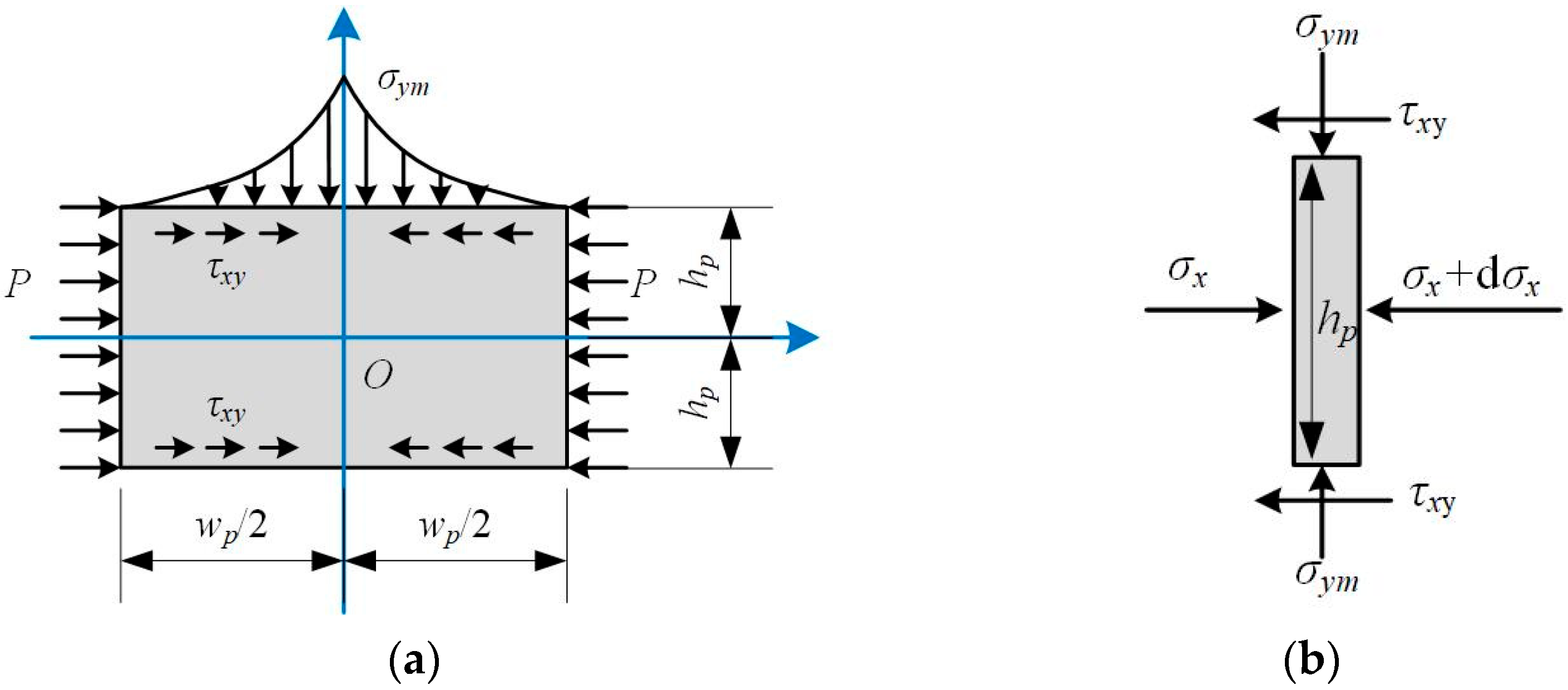
The gateway of the next longwall panel is affected by repeated mining, and its stress environment is complex. Under the action of front and side abutment pressure caused by mining in the current longwall face, the elastic zone in the pillar is completely destroyed and enters the residual stage. According to the elastoplastic constitutive model of coal, the stress relationship inside the pillar can be expressed as Equation (5). The mechanical model of the narrow pillar is established, as shown in Figure 2a, where σym is the peak stress; hp and wp are the height and width, respectively; τxy is the shear stress at the interface of the coal seam, calculated by Equation (6):
σ y = λ σ x + σ r
τ x y = f σ y
where f is the friction coefficient at the interface between the coal seam and roof and floor; σr is the residual strength of coal.
Take a micro-element with a width of dx inside the pillar (Figure 2b), whose height is hp, and the top and bottom interfaces are subjected to vertical normal stress and horizontal shear stress, while the left and right sides are subjected to horizontal normal stress. According to the stress equilibrium conditions in the horizontal direction, the following equation can be obtained:
d σ x d x = 2 τ x y h p
According to the stress boundary conditions, the following conditions are met at x = wp/2:
σ x | x = w p 2 = P
By combining Equations (5)–(8), the expression for horizontal stress can be obtained.
σ x = σ r λ P exp f λ h p w p 2 x σ r λ σ y = σ r λ P exp f λ h p w p 2 x
The peak stress inside the coal pillar can be calculated by
σ y m = σ r λ P exp f λ w p h p
It can be seen that the peak stress within the coal pillar is positively correlated with the width-to-height ratio of the pillar and negatively correlated with the artificial support to the pillar. The narrow pillar must be reinforced and supported to improve its bearing capacity, in order to maintain the stability of the surrounding rock [48]. The strength of coal pillars under different shapes can be expressed as [49]:
σ strength = 0.65 σ c w p 0.30 h p 0.59
where σc is the uniaxial compressive strength of the coal. Therefore, the peak stress within the coal pillar should satisfy the following condition:
σ y m σ strength
The required support strength to maintain the stability of the narrow pillar can be obtained as follows:
P 0.65 σ c λ w p 0.30 h p 0.59 exp f λ w p h p + σ r λ

2.3. Implement Roof Cutting to Optimize the Stress Environment of the Gateway

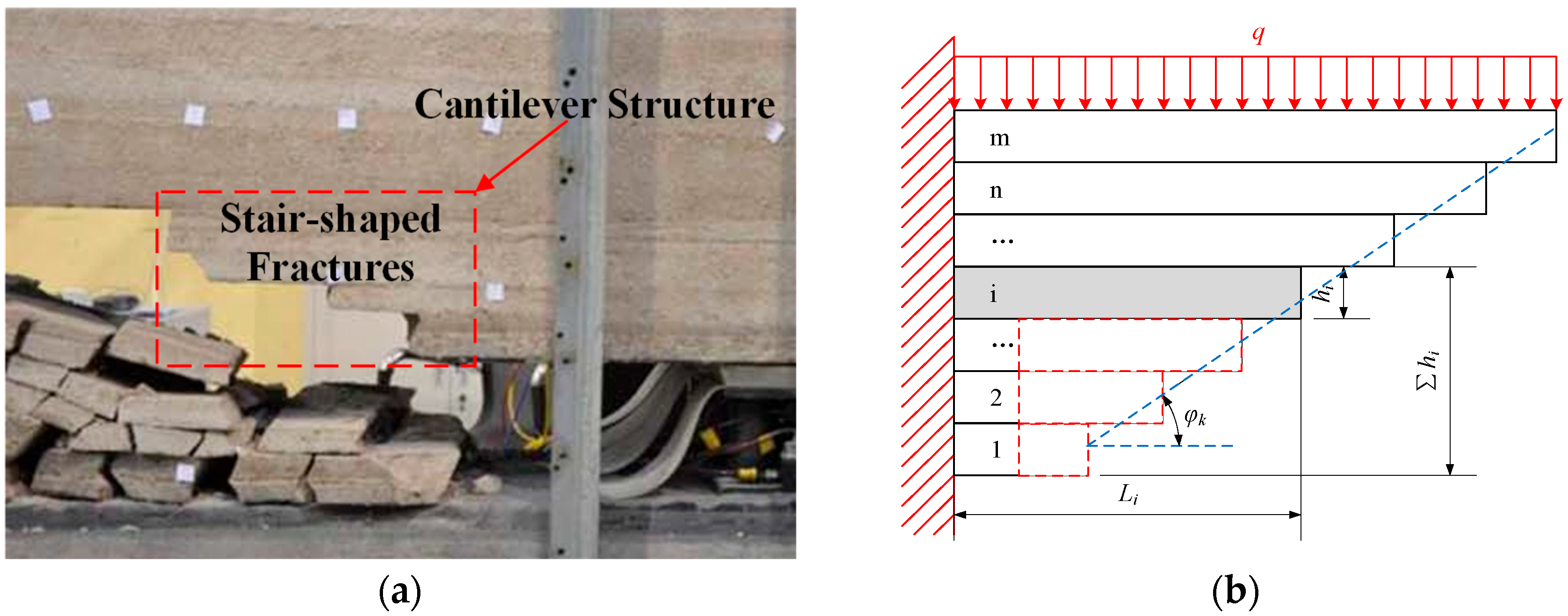
The overlying roof exhibits distinct layered collapses and step-shaped fracture structures (Figure 3a). The high side abutment pressure generated by this is the main reason for the strong mining pressure in the gateway of the adjacent panel, which exacerbates the difficulty in controlling the stability of the surrounding rock of the gateway [25,50,51]. The use of roof pre-splitting and pressure relief technology promotes the collapse of low-level cantilever structures and reduces their support for high-level cantilever structures, thereby facilitating the collapse. In addition, the cantilever structures quickly and completely collapse, filling the gob and avoiding deformation or damage to the gateway due to prolonged exposure to a high-stress environment [27,52,53], effectively controlling the surrounding rock [54].

2.3.1. Design of Roof Pre-Splitting Height

The process of roof pre-splitting actually weakens the mechanical properties of the pre-splitting surface artificially, causing the cantilever structure to fracture along the surface under its own weight and overlying load. Its application not only promotes the collapse of the roof within the pre-splitting height but also affects the fracture of several overlying strata. Therefore, the height of the pre-splitting roof is less than or equal to the height of the roof collapse.
Taking the cantilever structure within collapse height after mining as the research object, the mechanical model is established, as shown in Figure 3b. There are m rock layers within the range of roof collapse height. Li, li, hi, and ∑hi represent the cantilever length, the ultimate fracture length, the thickness, and height of the i-th roof, respectively. φk is the roof falling angle.
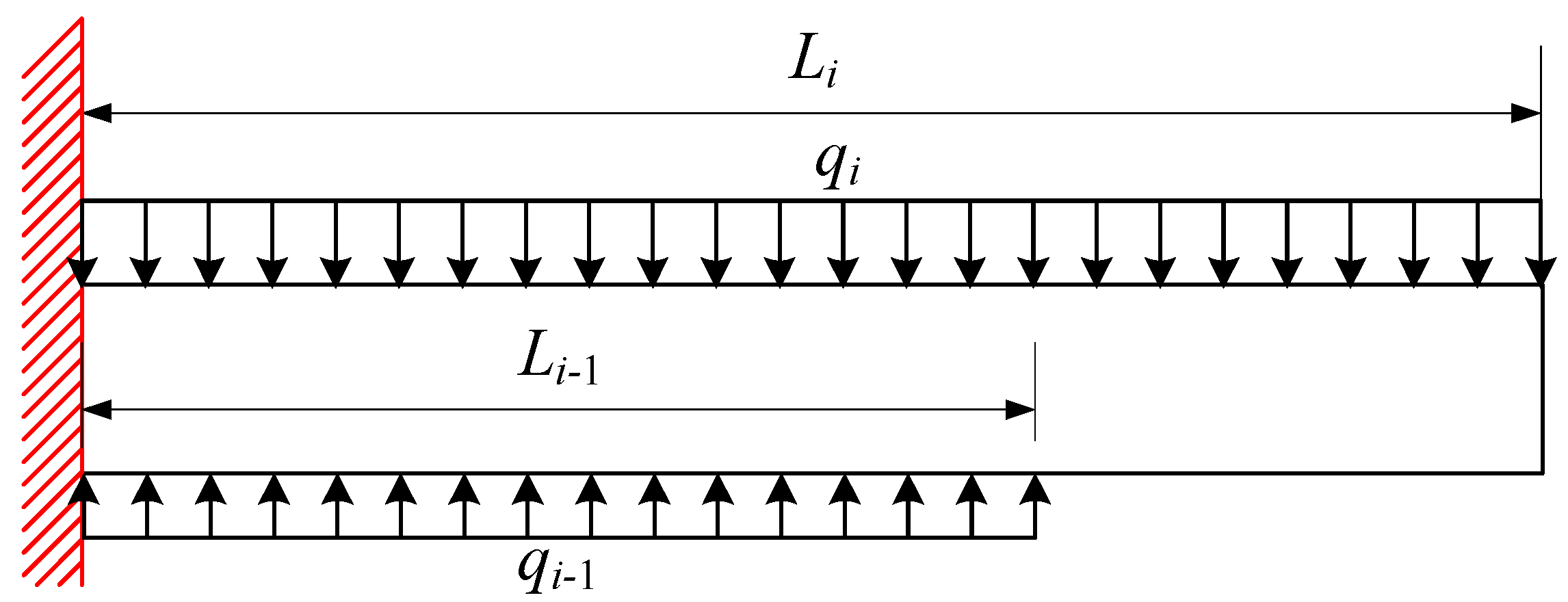
The mechanical state of the cantilever structure of any layer of the roof is similar and jointly controlled by the overlying and underlying roof strata. Therefore, a mechanical analysis model for the cantilever structure of the i-th layer roof is established (Figure 4), where qi and Mi represent the load concentration and the internal bending moment of the i-th layer roof, respectively.
According to the relationship of moment balance and stress-bending moment, the maximum tensile stress on the i-th floor roof structure can be obtained.
σ t m i = 3 q i l i 2 q i 1 l i 1 2 / h i 2
Then, the ultimate fracture length of the i-th layer roof can be calculated.
l i = σ t m i h i 2 3 q i + q i 1 l i 1 2 q i
When the i−1st roof layer is cut off, the value of li−1 decreases, causing the limit fracture length li to decrease. Meanwhile, the cantilever length of the i-th layer roof can be calculated based on collapse angle φk and position of the roof:
L i = h i h 1 / t a n φ k + L 1
where L1 is the length of the lowest cantilever structure, which can be obtained through on-site observation. When the cantilever length of the i-th layer roof exceeds its maximum fracture length, the i-th layer roof can automatically collapse. That is, after cutting off the underlying roof, the i-th layer roof can automatically collapse under the following conditions:
L i   >   l i
To ensure that the collapse and fragmentation of the roof can fill the gob and provide effective support for the gob roof, the index of filling degree of gob, fgd, needs to meet the following:
f g d = h c + M k i h i > 0 h c = h i
where ki is the hulking coefficient of the i-th of the roof rock layer; hc is the total height of roof collapse; and M is the mining height.

2.3.2. Design of Pre-Splitting Cutting Angle

Within the range of pre-splitting height, due to the obvious layered collapse pattern of the roof cantilever structure, the rock layer usually breaks further after its underlying rock layer breaks, and there is obvious separation from its overlying rock layer. Therefore, taking any layer of cantilever structure within the range of pre-splitting height as the research object, a mechanical analysis model of a single-layer cantilever structure is established, as shown in Figure 5.
The fracture of the roof cantilever structure along the pre-splitting surface can be divided into two stages. The first stage is before the cantilever structure touches the gangue, and under the action of overlying load, it undergoes rotational fracture with point O as the axis. The mechanical model of the cantilever structure’s rotational fracture, in Figure 5a, shows that a certain cutting angle can make the maximum tensile stress on the pre-splitting surface exceed its tensile strength, allowing the cantilever structure to break smoothly.
In Figure 5a, the maximum tensile stress on the pre-splitting surface in the first stage is
σ t m = 3 q l h tan α h 2
where q is the equivalent concentration of overlying load of the rock layer cantilever structure, in MPa; l is the fracture length, in m; h is the thickness, in m; α is the cutting angle, in °.
It is worth noting that in the actual process of roof pre-splitting, the pre-splitting surface is often difficult to penetrate fully, and the degree of weakening of the surface directly affects the effect of pre-splitting. Therefore, in the design process, the weakening coefficient of the surface kw should be added. To ensure the smooth fracture of the cantilever structure, the cutting angle should meet the following requirements:
σ t m > k w σ t
where kw is the weakening coefficient of the pre-splitting surface; σt is the maximum tensile strength of the roof, in MPa. Therefore, it can be determined that the pre-splitting angle should satisfy the condition of the state function fs1:
f s 1 = 3 q l h tan α h 2 k w σ t > 0
In the second stage, after the cantilever structure contacts the gangue, it undergoes shear failure along the pre-splitting surface under overlying load. As shown in Figure 5b, in this stage, the relationship can be obtained based on the moment and force balance of the roof block:
F A + R cos α q l T sin α = 0 F B T cos α R sin α = 0 q l 2 2 + F B h 2 F A l = 0
where T is the thrust force exerted on the rock block perpendicular to the pre-splitting surface, in kN; R is the shear force exerted on the rock block parallel to the pre-splitting surface, in kN. FA and FB are the upward supporting force and frictional force generated by the contact between rock blocks and gangue, respectively. The value of FB is determined by both the friction coefficient frg and FA.
F B = f r g F A
By Equations (22) and (23), the force of the pre-splitting surface can be determined.
  R = l q l f r g h cos α + f r g l sin α 2 l f r g h cos α 2 + sin α 2 T = l q f r g h l sin α + f r g l cos α 2 l f r g h cos α 2 + sin α 2
When the roof rock block undergoes shear fracture along the pre-splitting surface, the value of the shear force T it receives will exceed the maximum frictional force generated by the positive pressure R on the surface. Therefore, the conditions for judging the instability of the second stage rock block are as follows:
R > T tan φ s
φs is the average internal friction angle of the pre-splitting surface. Under these conditions, the cutting angle α should satisfy the following relationship for the state function fs2:
f s 2 = l q l f r g h cos α φ s + f r g l sin α φ s cos φ s 2 l f r g h > 0

3. Case Study

The Tashan Mine, characterized by typical burial depth, seam thickness, and hard roof lithology, was selected as a representative case study. Based on the proposed design framework, the methodology was applied to its geological conditions, where theoretical parameters were determined and corresponding technical processes were developed to validate the engineering effectiveness of narrow pillar gateway protection.

3.1. Geological and Geotechnical Overview

The average burial depth of longwall faces 8311 and 8312 in Tashan Mine is 510 m, and the average thickness and inclination angle of the coal seam are 3.4 m and 4°, respectively, as shown in Figure 6a. Gateways 2311 and 2312 are both rectangular, 5 m wide and 3.4 m high. To improve coal resource recovery, ensure mining continuity, and avoid the formation of isolated working faces, a narrow pillar was retained between the two longwall faces for gateway protection (Figure 6c). The lithology bar chart of the roof and floor is shown in Figure 6b, and the mechanical parameters of the coal and rock are shown in Table 1.

3.2. Design Parameters

In order to design the narrow pillar between panels 2311 and 2312, the width of pillar, strength of pillar support, the height and angle of the roof pre-splitting were designed.
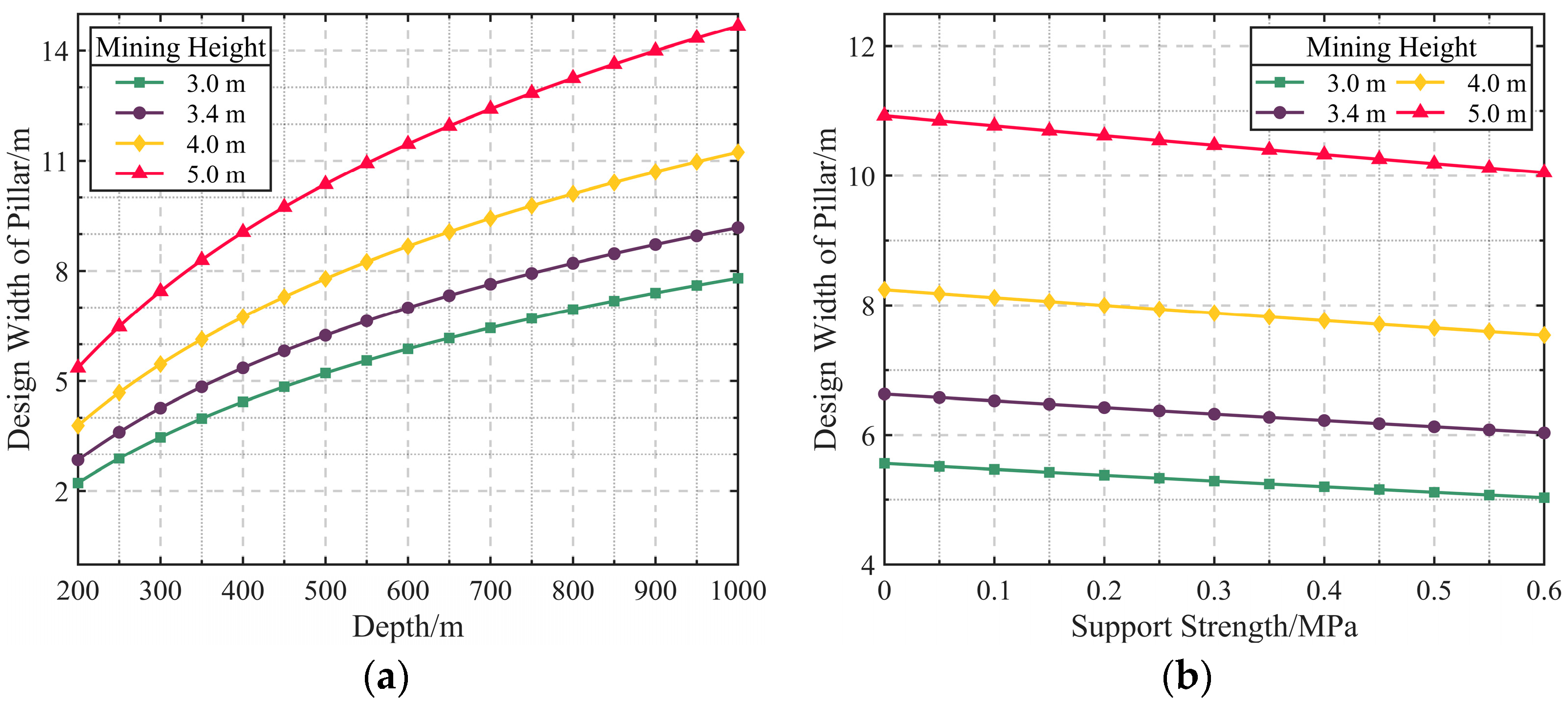
In Figure 7, the design width of the narrow coal pillar is positively correlated with both burial depth and mining height, with mining height having a particularly significant impact. The increase in burial depth primarily increases the roof load on the pillar, requiring a larger width to meet the bearing capacity. The increase in mining height leads to a decrease in the coal pillar width-to-height ratio, which reduces the relative bearing volume of the pillar and weakens its ability to support and distribute the load. Although an increase in support strength can somewhat reduce the need for the coal pillar width, its effect is less pronounced than that of burial depth and mining height. For Tashan Mine, the mining height of 3.4 m corresponds to the purple curve. Combined with a burial depth of 510 m, the design width of the narrow coal pillar can be determined as 6 m, which does not exceed the upper design limit.
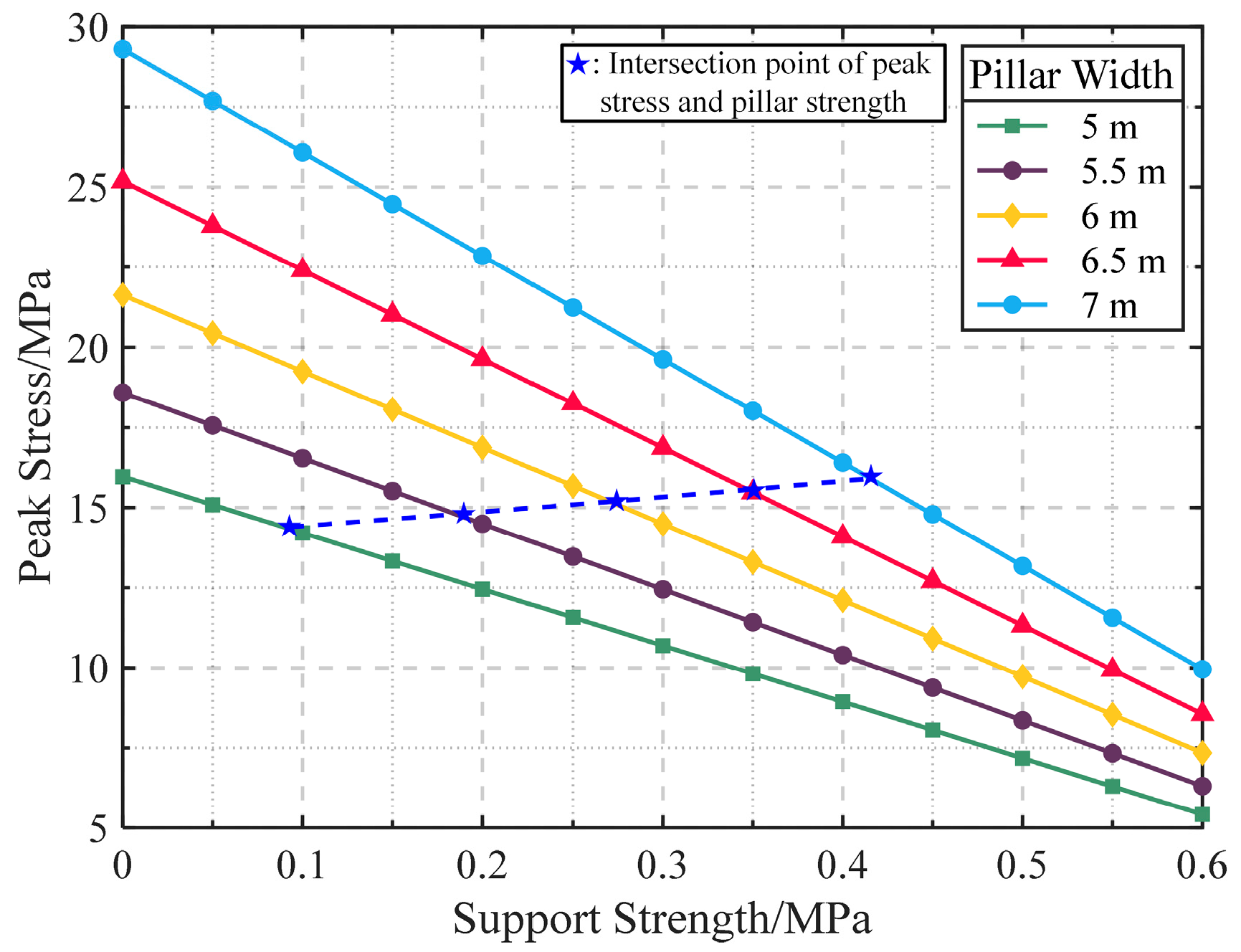
As shown in Figure 8, when the coal pillar width increases within the range of 5 to 7 m, its peak stress is positively correlated with the design width. Increasing the support strength can effectively reduce the peak stress within the coal pillar. The intersection of peak stress and support strength shows a gradually upward trend, indicating that as the pillar width increases, the bearing capacity of the pillar improves but the growth is smaller than the rise in peak stress. This means that maintaining the stability of the pillar requires greater support strength. For the 6-meter-wide coal pillar design at Tashan Mine, the critical support strength is 0.273 MPa, and a support strength of 0.3 MPa can be selected in practical design to meet the requirements.
To effectively control the high-stress environment in the gateway, it is necessary to ensure that the roof above the gateway collapses in time. Figure 9 shows that the natural cantilever lengths of the first and second roof layers (immediate roof, fine-grained sandstone, and basic roof, siltstone) are 10 m and 14.29 m, respectively, both shorter than their ultimate fracture lengths (12.2 m and 15.47 m), making them unable to collapse naturally. Therefore, the cantilever length must be reduced through cutting to below the ultimate fracture length, creating conditions for the collapse of the upper roof layers. The natural cantilever lengths of the third to fifth roof layers exceed their ultimate fracture lengths, allowing them to collapse naturally.
Hence, the first two roof layers are set as cutting targets, and the pre-splitting height should be at least greater than their total thickness of 7.2 m. To facilitate construction, the pre-splitting height is set at 8 m. At the same time, to ensure effective filling of the gob after the roof collapses, it is required that the filling degree of the gob be greater than 0. Due to the relatively hard roof, the average hulking coefficient of the fallen roof rock is taken as 1.25 [56]. The blue curve in Figure 9 shows that as the roof collapses layer by layer, the gob filling degree gradually increases. After the collapse of the fourth roof layer, the filling degree becomes significantly greater than 0, indicating that this cutting design can completely fill the gob and effectively support the roof.
To ensure that the roof can collapse smoothly after the cutting operation, the state function values (Equations (21) and (26)) for both stages must exceed 0. As shown in Figure 10, during the two roof instability stages, cutting the siltstone and fine-grained sandstone with different cutting angles results in consistent evolution patterns of the state function, though the evolution rates differ. In Stage 1, the state function values of both roof layers decrease monotonically, with a more significant decrease in siltstone, indicating a higher sensitivity to changes in the cutting angle. When the cutting angles are less than 10.60° (fine-grained sandstone) and 27.90° (siltstone), the cutting requirements for Stage 1 are met. In Stage 2, the state function values of both roof layers show a nonlinear change, initially increasing and then decreasing. Siltstone remains slightly more sensitive to changes in the cutting angle compared to fine-grained sandstone. When the cutting angles exceed −31.14° (fine-grained sandstone) and −32.57° (siltstone), the cutting requirements for Stage 2 are met. Based on this analysis, siltstone has a broader range of cutting angles in both stages, suggesting that cutting through siltstone is easier. To ensure effective cutting of both roof layers, the cutting angle range is determined to be [−31.14°, 10.60°]. Considering the convenience of on-site construction, the final cutting angle for the operation is set to 0°.

3.3. Mechanism of Mining Pressure Manifestation

Since the gateways on both sides of the narrow pillar were excavated before working face 8312 was mined, the stress evolution law of the surrounding rock is different from that of conventional double gateway excavation with the wide coal pillar or gateway driven along the gob side with the narrow coal pillar. To ensure the smooth implementation of the key technology for the surrounding rock control of the gateway with the narrow coal pillar, it is necessary to clarify the mechanism of mine pressure manifestation under the influence of repeated mining and, based on this, design the key technical process flow.
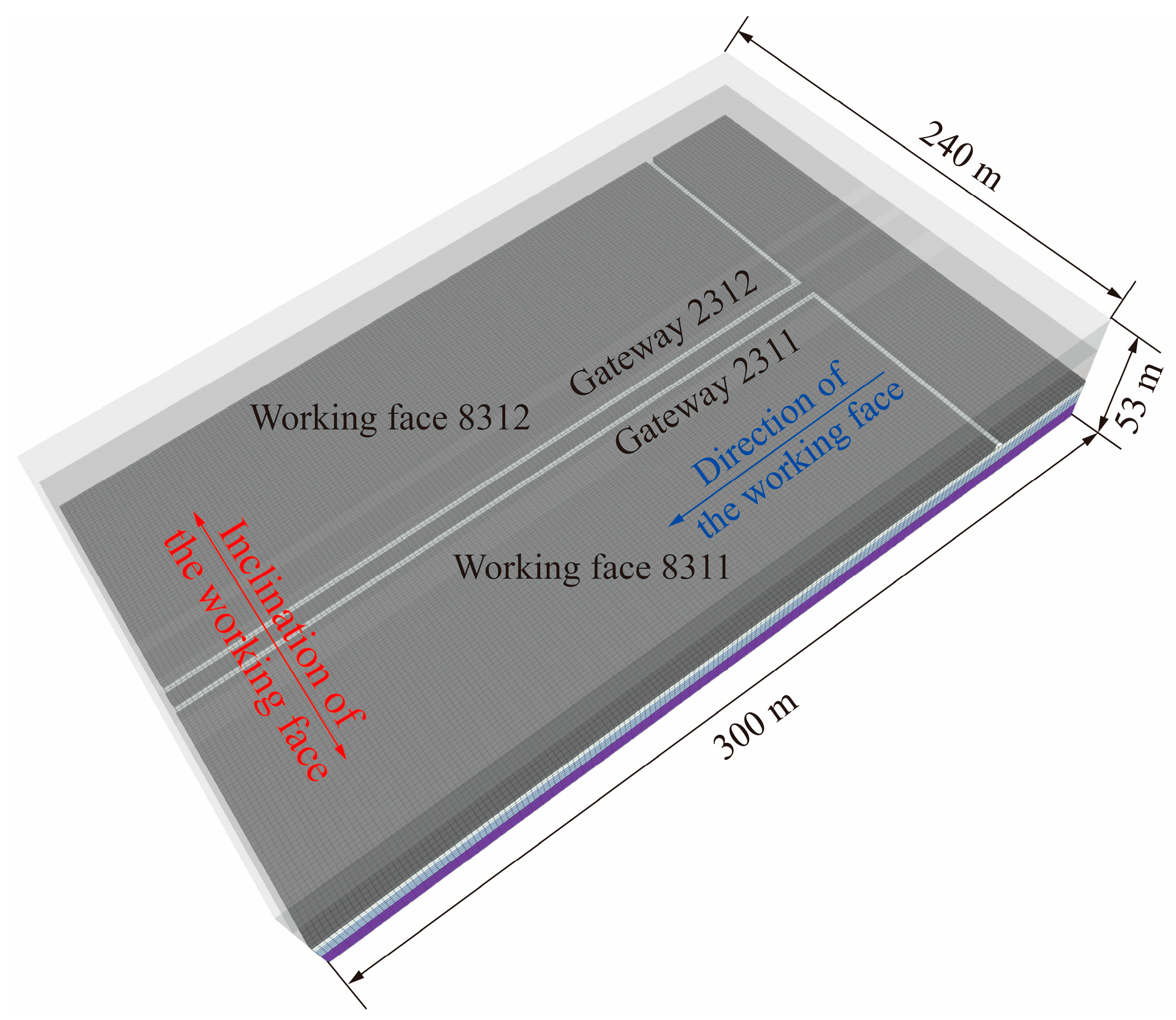
Based on the engineering geological conditions of Tashan Mine, numerical calculation methods were used to study the mechanism of mining pressure manifestation under the condition of gateway protection with the narrow pillar. The size of the model is 300 m in length, 240 m in width, and 53 m in height, as shown in Figure 11. The boundary conditions are set around the model to horizontal constraints and the bottom boundary to vertical constraints. A uniformly distributed load of 12 MPa is applied at the top to simulate the gravity of the overlying strata.
The Strain-Softening and Mohr–Coulomb models were used to simulate coal seams and other rock strata. The mechanical parameters of coal and rock are shown in Table 2 and Table 3. The gob was simulated using the Double Yield model, and the parameters were calibrated using trial and error based on the theoretical results of the Salamon model. The simulated mining sequence is consistent with the actual sequence. After the excavation of the gateways was completed, the mining of working faces 8311 and 8312 was carried out sequentially.
As shown in Figure 12a, during the mining process of panel 8311, the two ribs of gateway 2312 underwent a complex loading and unloading process, and the stress distribution characteristics in the coal pillar and the entity coal rib changed significantly.
Figure 12b shows the evolution law of stress in the surrounding rock of gateway 2312 with the advancement of the working face. MLs (measuring lines) 1 to 4 were arranged at the center of the coal pillar, 3 m, 6 m, and 12 m inside the coal wall. According to the stress state of the surrounding rock, gateway 2312 was divided into four zones: excavation influence zone, joint-bearing zone, coal-rib-bearing zone, and stress stability zone.
(1)
Excavation influence zone (outside the range of 50 m ahead of panel 8311). This area is less affected by the front abutment pressure but, due to gateway excavation, the surface of the coal body transitions from a three-dimensional stress state to a two-dimensional stress state, and its strength decreased. Therefore, the surface of the coal body of gateway 2312 was damaged, with a vertical stress of less than 6 MPa and only half of the virgin stress, while the internal vertical stress of the coal pillar reached 19.8 MPa, with a concentration coefficient of 1.56.
(2)
Joint-bearing zone (within 50 m head of panel 8311). Due to the influence of abutment pressure, the stress in the surrounding rock of gateway 2312 significantly increased. The narrow coal pillar began to fail under the action of front abutment pressure, but the overall coal pillar was still in an elastic state, and the peak stress was located inside the coal pillar. At this time, the overlying strata load was still jointly carried by the coal pillar and coal rib.
(3)
Coal-rib-bearing zone (within a lag range of 50 m behind panel 8311). The narrow coal pillar entered a plastic state under the abutment pressure, and the bearing capacity was greatly reduced. The peak stress of the surrounding rock was transferred from the inside of the coal pillar to the entity coal and gradually moved towards the depth of the entity coal. ML 1 to 4 reached peak values of 27.8 MPa, 29.2 MPa, 37.4 MPa, and 27.1 MPa at 137.5 m, 105 m, 60 m, and 60 m, respectively. At this time, the overlying strata load was mainly carried by the coal rib. In addition, the analysis showed that the impact range of front abutment pressure (LF), the severe impact range of side abutment pressure (LL), and the impact range of side abutment pressure (LL) were 50 m, 25 m, and 75 m, respectively.
(4)
Stress stability zone (outside the range of 50 m behind panel 8311). The surrounding rock stress caused by the mining of the working face became redistributed, and the gangue in the gob and the coal wall in working face 8312 became the main load-bearing structure. The surrounding rock of the gateway was relatively stable. At this point, the peak stress inside the coal pillar was about 10 MPa, which still has a certain bearing capacity.

3.4. Technical Process Based on Theoretical Parameters

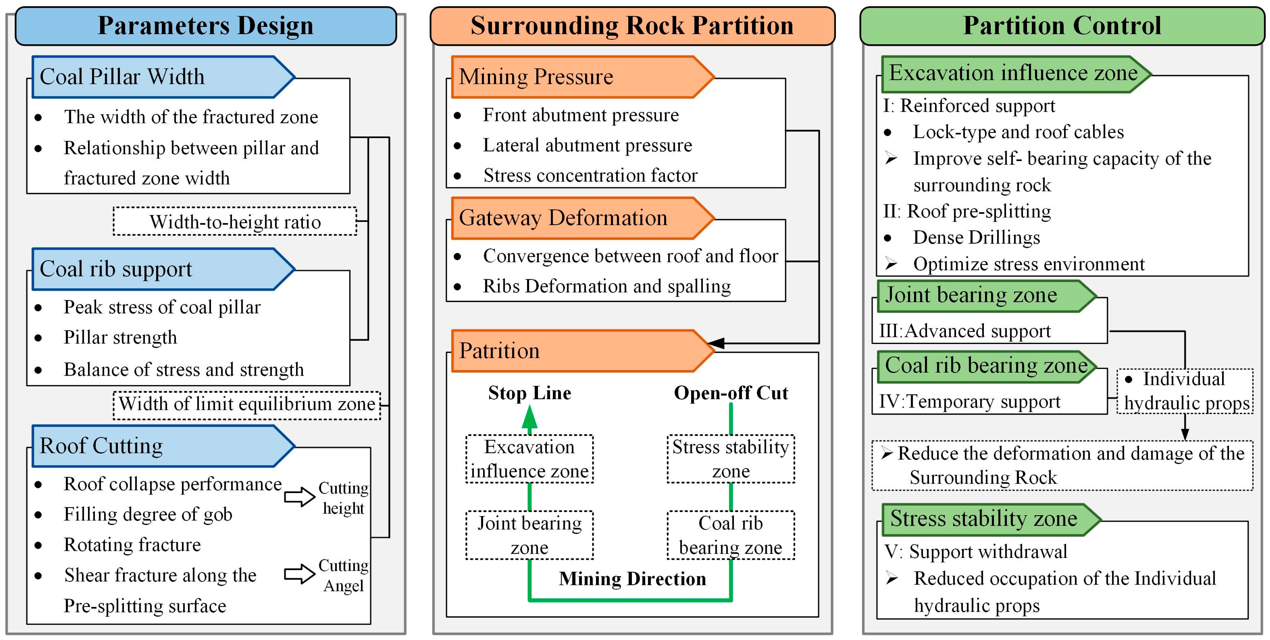
As shown in Figure 13, after the excavation, the normal service of gateways 2311 and 2312 in the production process of working faces 8311 and 8312 was ensured via the following technical process divided into four steps:
(1)
In the excavation influence zone, the lock-type cables and the roof cables were respectively used to reinforce the support of the narrow coal pillar and the roof of the gateway in working face 8312. The surrounding rock of both gateways in this area was in a stable state with relatively little deformation. Timely reinforcement and support can more effectively exert the effect of bolts and cables. In order to prevent severe fragmentation of the pillar after the influence of a single mining operation, using only conventional bolt or cable support was insufficient to meet the reinforcement requirements. Therefore, it is necessary to use high-strength 1 × 19 cables with 21.8 mm in diameter and 6600 mm in length, combined with Q335 bolts with 22 mm in diameter and 2000 mm in length, to reinforce the narrow pillar. According to the calculation results of a reasonable coal pillar support strength of 0.3MPa, the designed spacing and row spacing of lock-type cables for the narrow pillar were 1600 mm and 2400 mm, respectively. Both spacing and row spacing of the bolts of two ribs were designed to be 1000 mm. The roof was reinforced with Φ21.8 mm × 9300 mm 1 × 19 steel strand cables, with one cable per row and a row spacing of 2.4 m, as shown in Figure 14c.
(2)
For the excavation influence zone, outside the range of front abutment pressure in working face 8311, directional pre-splitting of the roof by dense drilling was implemented in gateway 2311 (with a height of 8 m and a pre-splitting angle of 0°). Along the advancing direction of panel 8311, dense drilling holes were constructed 0.5 m from the narrow pillar with a hole diameter of 30 mm and spacing of 250 mm, giving a hole-to-spacing ratio of 8.33. The drilling angle was 0° ± 5° along the plumb line direction, and the height was 9.0 m. The roof pre-splitting through dense drilling helped to further develop and fully connect the pre-splitting surface under mining stress, further promoting the timely collapse of the cantilever structure and reducing the stress of the surrounding rock in the gateway of working face 8312.
(3)
Individual hydraulic props were used (one per row, with a row spacing of 0.5 m, working resistance of 300 kN, maximum height of 4 m) to provide advanced support in the joint-bearing zone of panel 8311 and, at the same time, individual hydraulic props were used for temporary support in both the joint-bearing zone and coal-rib-bearing zone of the gateway in panel 8312. The stress transfer process within the joint-bearing zone and coal-rib-bearing zone continued, and the combination of active and passive support was used to enhance the strength of surrounding rock support, which helps maintain gateway stability.
(4)
After the gateway entered the stress stability zone, the cantilever structure collapsed and filled the gob, which could bear the load on the overlying strata. The bearing performance of the surrounding rock formed a new balance with the stress. As the working face advanced, the passive support equipment could be gradually withdrawn to reduce its occupancy.
Based on this, the reasonable timing for key processes such as support reinforcement, roof pre-splitting, and advanced support can be determined, as shown in Figure 14.
(1)
To ensure the normal service of gateway 2312 under the influence of repeated mining, it is necessary to reinforce the support in a timely manner after its excavation, which needs to be completed within a range of 50 m ahead of panel 8311.
(2)
The roof pre-splitting operation should be completed within a range of 50 m ahead of panel 8311 but should lag the support reinforcement.
(3)
To avoid the impact of mining on working face 8311, which may cause the two gateways to be subjected to front abutment pressure and affect normal use, the advanced support area is set up within a range of 30–50 m ahead of the longwall face, and passive support is used to temporarily support gateway 2312 within a range of 50 m behind panel 8311.
(4)
After the side abutment pressure of the 8311 gob stabilizes, the individual hydraulic props are retreated and moved forward.

4. Results

During the mining process of panel 8311, the stress of the surrounding rock and surface displacement of the gateway in panel 8312 were monitored. Typical measuring stations were selected to analyze the implementation effect of this technology from two aspects: the pre-splitting effect of the roof and the stability of the surrounding rock of the gateway.

4.1. Force Monitoring of Bolts and Cables

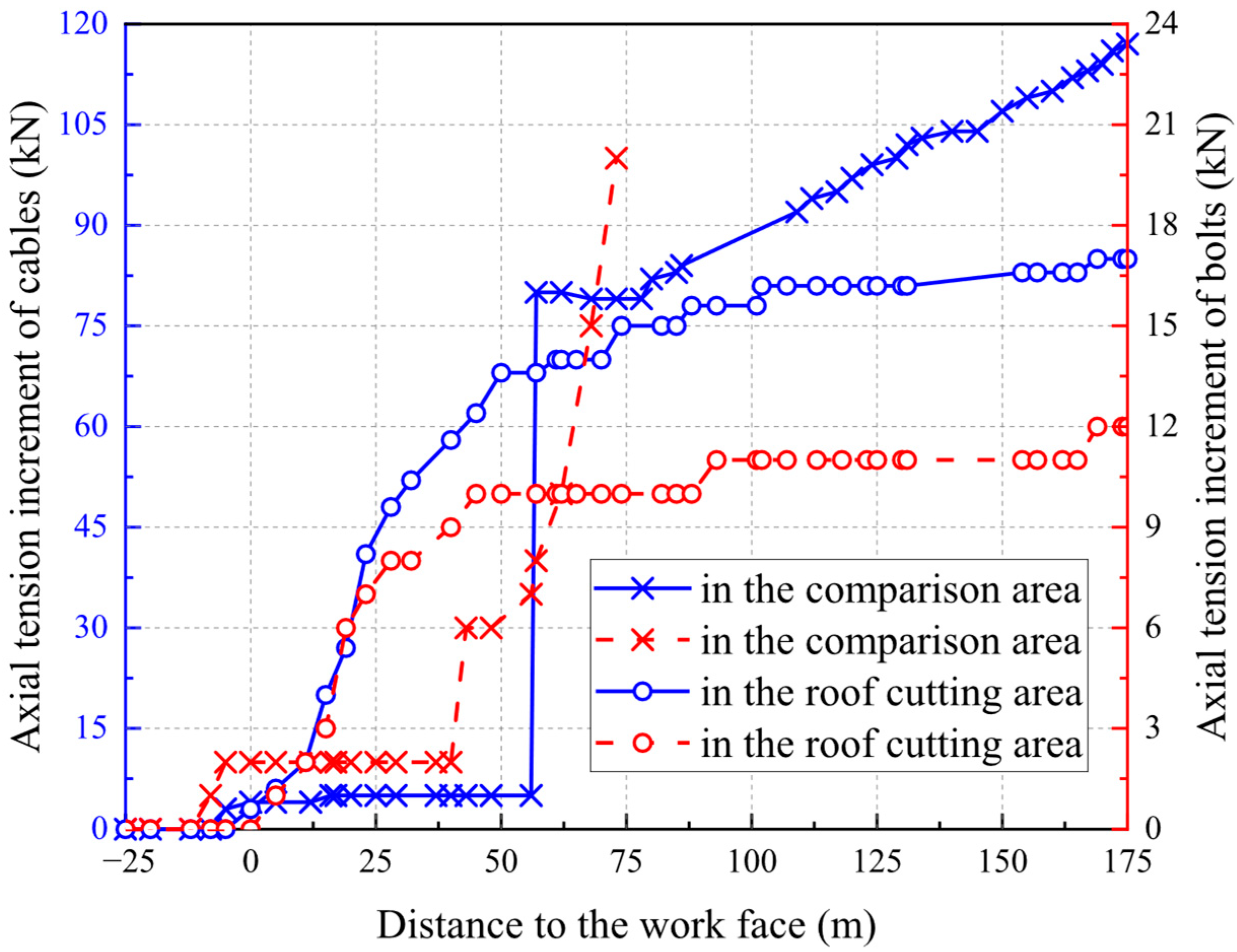
By using stress gauges for bolts and cables, the stress situation of bolts and cables in gateway 2312 was tracked and monitored. Pre-splitting effect measurement stations were set up in the roof cutting area and the comparison area (without pre-splitting of the roof), with two stress gauges installed at each station to monitor the bolts and cables in the center of the gateway roof. The monitoring results are shown in Figure 15. It should be noted that the monitoring gauge in the comparison area failed when it lagged panel 8311 by 75 m. Figure 15 only shows the force monitoring of the bolts before the failure.
The results show that during the mining process of panel 8311, the tensile increment of the bolts and cables in the roof cutting area was significantly lower than that in the control area. By the end of the industrial test, the tension increment of the bolts and cables in the comparison area had reached 119 kN and had not yet stabilized. The tensile increment of the bolts and cables in the roof cutting area remained stable at 10 kN and 80 kN respectively, when lagging the working face by 90 m. This indicated that the pre-splitting of the roof not only cut off the cantilever structure on the gob side of panel 8311, effectively reducing the stress of the surrounding rock of the gateway in this area, but also promoted the collapse of the cantilever structure and accelerated the process of adjusting the stress.

4.2. Gateway Deformation Monitoring

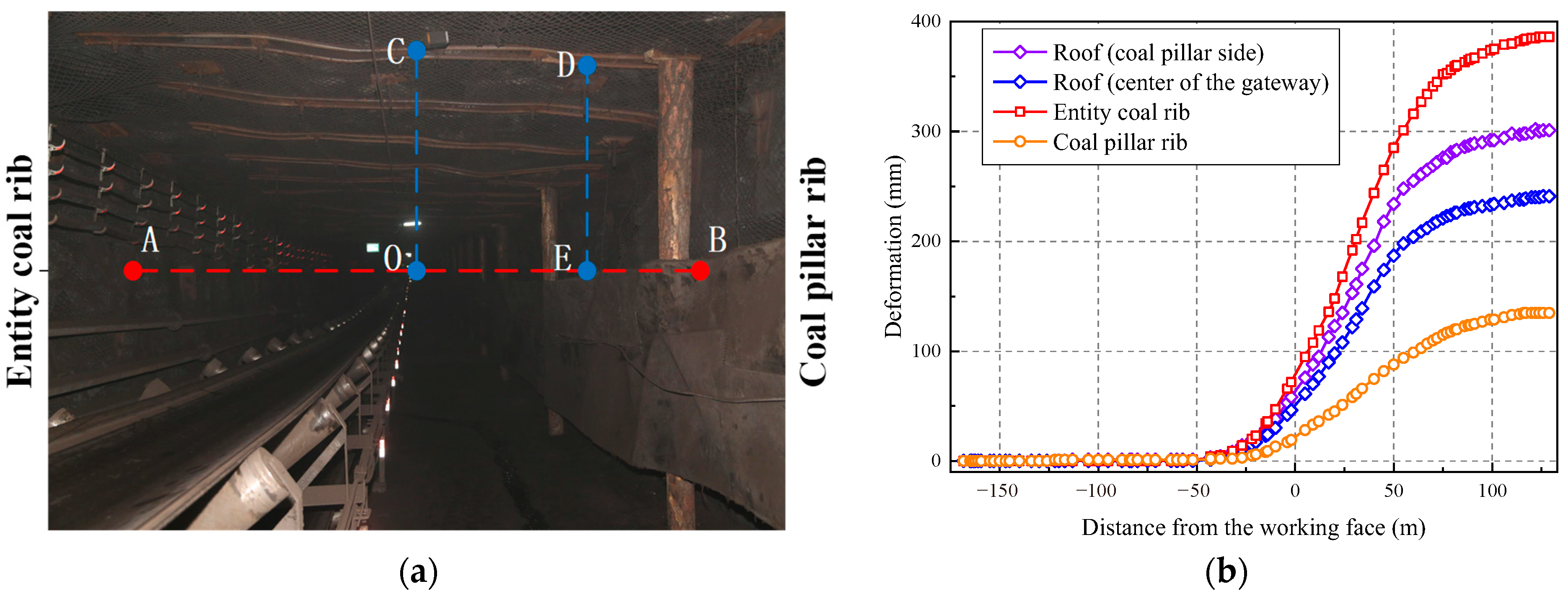
The cross-measurement method shown in Figure 16 a was used to track and monitor the deformation of the surrounding rock in gateway 2312 during the mining process of longwall face 8311. AO, BO, CO, and DE represent the deformations of the coal pillar rib, entity coal rib, roof center, and roof near the coal pillar side, respectively.
The monitoring results (Figure 16b) indicate that during the mining of panel 8311, gateway 2312 experienced minimal deformation, and its stability was effectively maintained. The surrounding rock of gateway 2312 within a range of 40 m in front of the working face began to deform under front abutment stress, and the deformation outside a range of 90 m behind the working face gradually stabilized. The roof of gateway 2312 showed uneven subsidence, with a maximum subsidence of 241 mm in the center and 302 mm on the side of the coal pillar. There was a significant difference in the deformation of the ribs, with a maximum deformation of 135 mm for the entity coal and 386 mm for the narrow pillar.

5. Discussion and Conclusions

5.1. Discussion

With the continuous advancement of research methods and field engineering technologies, coal pillar stability control has shown a diversified development trend. Previous study [57] proposed a method for determining the upper limit of the roof-cutting angle, which is consistent with the second-stage roof fracturing model established in this paper. Building on this, our study further determined the lower limit of the roof-cutting angle based on the initial roof fracturing law, thereby improving the definition of the parameter interval. Regarding roof-cutting height, studies [57,58,59] mostly adopted a layer-by-layer tensile strength calculation method, whereas our research approached the problem from the perspective of pre-splitting to weaken roof strength. On this basis, a goaf compaction coefficient was introduced to ensure that, after roof breakage, the goaf can still be effectively filled, thereby achieving better control of roof pressure. In addition to the narrow coal pillar technology, backfilling mining technology also plays an important role in coal pillar stability: even a moderate level of lateral confinement can significantly suppress spalling and increase pillar strength [60], and residual strength can be elevated from nearly zero under extremely low confinement while also changing the failure mode [61]. However, the strengthening effect of cohesive backfill or of pillars with small width-to-height ratios is relatively limited [62,63]. Meanwhile, non-pillar mining technologies can effectively improve surrounding rock stability through roof cutting, stress equilibrium, and synergistic support, manifested in coordinated measures such as roof cutting for stress relief, dynamic pressure-bearing supports, and long-term stability of cable bolts [64]. By eliminating pillar-induced stress concentration and combining with roof-cutting confinement [65], these methods can significantly reduce the maximum roof deformation and the depth of floor damage [66]. Compared with backfilling, the present method focuses more directly on coal pillar stability itself, with little impact on the extraction procedure, whereas backfilling adds extra operational steps during mining but provides more significant overall safety and environmental benefits. Compared with non-pillar mining, the present method offers broader adaptability under varied engineering conditions, lower risks, and easier control of pillar stability, while non-pillar methods can further improve coal recovery rates.
Focusing on the application scenario of the design method proposed in this study, the case mine is characterized by favorable roof and floor lithology. To enhance the generalizability of the method, further consideration of its applicability and improvement strategies under special conditions are required. In conventional mining environments, fluctuations in ground temperature and humidity exert negligible effects on the mechanical properties of coal pillars and can largely be ignored. By contrast, water ingress exerts a much greater influence, as dripping water increases coal and rock moisture content, reducing strength parameters and effective stress. Such risks can be mitigated by introducing reduction factors, conducting laboratory tests, and adopting drainage measures. Under dynamic loading (e.g., earthquakes, mine tremors), the superposition of static and dynamic stresses accelerates coal pillar damage accumulation. This can be addressed by combining roof-cutting stress relief (e.g., hydraulic slotting, pre-split blasting) with goaf backfilling, while also incorporating coupled static–dynamic load effects into coal pillar width design to ensure sufficient safety factors. Under different roof conditions, hard roofs require artificial cutting to induce fracturing, whereas weaker roofs demand priority in surrounding rock deformation control supported by combined reinforcement. For conventional coal seam thickness, narrow pillars remain generally applicable, but under large mining heights the stress concentration becomes more severe, necessitating enhanced roof-cutting, filling, and combined support to ensure stability. In deep or high-stress environments, multi-measure combinations of roof cutting and reinforcement are recommended, along with controlling pillar loading time, to mitigate long-term deformation. Under irregular coal seam geometries or complex geological structures, stress distribution within pillars becomes uneven, the plastic zone expands asymmetrically, and the applicability of narrow-pillar retention is limited; in such cases, alternative roadway control schemes should be adopted based on geological exploration results.
Nevertheless, certain limitations remain in promoting this method. In terms of process design, parameters need to be made more adaptable to varying mining conditions. For instance, although the effective cutting angle range applied in this study is relatively broad, future studies should further examine how cutting angle affects mining pressure evolution and supports strength requirements. This would help improve the comprehensive standards of roof-cutting design and enable more rational selection of cutting parameters and methods in practice. Meanwhile, the reinforcement mechanisms of bolts and cables, as well as the synergistic load-bearing effect of the roof–pillar–floor system, require systematic investigation in future research. In field applications, narrow pillars may cause stress concentration around roadways and high stress accumulation within pillars, thus increasing rockburst risks. Poor sealing may also lead to air leakage and airflow short circuits, allowing gas accumulated in the goaf to flow into the roadway and trigger gas over-limit hazards. Effective prevention and control of these risks rely on establishing comprehensive monitoring and early-warning systems. In terms of techno-economic feasibility, the establishment of a cost–benefit evaluation model for this method is also worthy of attention.

5.2. Conclusions

This research proposed and validated a key technology for controlling the surrounding rock of gateways supported by the narrow pillar. Taking the longwall faces 8311 and 8312 of Tashan Mine as engineering examples, a complete set of key technology systems for controlling the surrounding rock was proposed, including retaining width design optimization of the narrow pillar, support by rib strengthening and roof control, and roof pressure relief with pre-splitting. A technical process was formed by determining the key technical parameters. Based on this, industrial tests of gateways protected by the narrow pillar in longwall faces 8311 and 8312 of Tashan Mine were carried out, and significant surrounding rock control effects were achieved.
In terms of academic contributions, this research introduces an upper-limit criterion for narrow pillar width design, establishes a mechanical model of layered roof caving, and proposes a zoning-based design concept for narrow pillar protection. These contributions enrich the theoretical framework for coal pillar stability and provide new perspectives for studying roadway stability under complex geological conditions. From a broader perspective, the findings offer practical guidance for roadway stability control in deep, high-stress, and geologically complex mining environments, and hold reference value for emerging international approaches such as pillarless mining, backfilling, and intelligent ground control. Although the present case focuses on hard roof gateways, which differ in cantilever characteristics from conventional or soft rock conditions, further research is needed to refine the applicability of parameter design across varying geological settings and to explore how roof cutting angles affect mining pressure evolution and support requirements. Such studies will help establish more comprehensive design criteria and advance practical engineering applications.

Author Contributions

Conceptualization, Y.L. and Q.Y.; methodology, Y.L.; software, Y.L.; formal analysis, H.L.; funding acquisition, Q.X.; investigation, Z.X.; resources, Q.Y. and Z.X.; data curation, H.H.; writing—original draft preparation, Y.L. and Z.X.; writing—review and editing, C.Z. and Q.Y.; visualization, Q.X.; supervision, Q.Y. All authors have read and agreed to the published version of the manuscript.

Funding

This research was financially supported by the National Natural Science Foundation of China (No. 52404153) and the Natural Science Foundation of Jiangsu Province (No. BK20241649).

Data Availability Statement

Data will be made available on request.

Conflicts of Interest

The authors declare no conflicts of interest.

References

  1. Nacke, L.; Vinichenko, V.; Cherp, A.; Jakhmola, A.; Jewell, J. Compensating Affected Parties Necessary for Rapid Coal Phase-out but Expensive If Extended to Major Emitters. Nat. Commun. 2024, 15, 3742. [Google Scholar] [CrossRef] [PubMed]
  2. Lin, B.; Shi, F. Coal Price, Economic Growth and Electricity Consumption in China under the Background of Energy Transition. Energy Policy 2024, 195, 114400. [Google Scholar] [CrossRef]
  3. Zhang, G.; Zang, C.; Chen, M.; Tao, G.; Li, Y.; Weng, H. Ground Response of Entries Driven Adjacent to a Retreating Longwall Panel. Int. J. Rock Mech. Min. Sci. 2021, 138, 104630. [Google Scholar] [CrossRef]
  4. Zhao, B.; Wang, F.; Liang, N.; Wang, W. Reasonable Segment Pillar Width and Its Control Technology for Fully Mechanized Top-Coal Caving Face with High Stress. J. Min. Saf. Eng. 2018, 35, 19–26. [Google Scholar] [CrossRef]
  5. Zhao, S.; Zuo, J.; Liu, L.; Wu, K. Study on the Retention of Large Mining Height and Small Coal Pillar under Thick and Hard Roof of Bayangaole Coal. Adv. Civ. Eng. 2021, 2021, 8837189. [Google Scholar] [CrossRef]
  6. Yang, R.; Zhu, Y.; Li, Y.; Li, W.; Lin, H. Coal Pillar Size Design and Surrounding Rock Control Techniques in Deep Longwall Entry. Arab. J. Geosci. 2020, 13, 453. [Google Scholar] [CrossRef]
  7. Zhang, Z.; Xu, C.; Cheng, G.; Von Lau, E. Towards Carbon Neutrality: A Comprehensive Study on the Utilization and Resource Recovery of Coal-Based Solid Wastes. Int. J. Coal Sci. Technol. 2025, 12, 34. [Google Scholar] [CrossRef]
  8. Ren, S.-H.; Jiao, X.-M.; Zheng, D.-Z.; Zhang, Y.-N.; Xie, H.-P.; Guo, Z.-Q. Demand and Fluctuation Range of China’s Coal Production under the Dual Carbon Target. Energy Rep. 2024, 11, 3267–3282. [Google Scholar] [CrossRef]
  9. Guo, W.B.; Hu, Y.H.; Hu, C.Q.; Li, L.X.; Wu, D.T.; Ge, Z.B. System and engineering practice of coal mining technology under buildings, water bodies and railways in China. Coal Sci. Technol. 2025, 53, 19–38. [Google Scholar] [CrossRef]
  10. Li, H.; Cao, J.; Tang, C.; Guo, G.; Chen, Y.; Zha, J.; Huang, W.; Yuan, Y.; Huang, J. Methods for Enhancing Resource Recovery Efficiency in Underground Coal Gasification to Promote Its Large-Scale Utilization. Geomech. Energy Environ. 2025, 41, 100651. [Google Scholar] [CrossRef]
  11. Li, X. Study on Stability of Big and Small Structure of Roadway Driving Along Next Goaf for Fully Mechanized Face. Ph.D. Thesis, China University of Mining &Technology, Xuzhou, China, 2000. [Google Scholar]
  12. Zhang, Z.; Deng, M.; Bai, J.; Yan, S.; Yu, X. Stability Control of Gob-Side Entry Retained under the Gob with Close Distance Coal Seams. Int. J. Min. Sci. Technol. 2021, 31, 321–332. [Google Scholar] [CrossRef]
  13. Hou, C.; Li, X. Stability Principle of Big and Small Structures of Rock Surrounding Roadway Driven along Goaf in Fully Mechanized Top Coal Caving Face. J. China Coal Soc. 2001, 26, 1–7. [Google Scholar]
  14. Li, X.; Zhao, Y.; He, W.; Li, L.; He, F. Study on Coal Pillar Width and Surrounding Rock Control of Gob-Side Entry in Extra-Thick Coal Seam. Geotech. Geol. Eng. 2020, 38, 6855–6868. [Google Scholar] [CrossRef]
  15. Yang, Y.; Sun, J.; Wang, W.; Zhang, R. Research on Coal Pillar Width and Support Design of Gob-Side Entry. Geotech. Geol. Eng. 2023, 41, 847–860. [Google Scholar] [CrossRef]
  16. He, W.; He, F.; Zhao, Y. Field and Simulation Study of the Rational Coal Pillar Width in Extra-Thick Coal Seams. Energy Sci. Eng. 2020, 8, 627–646. [Google Scholar] [CrossRef]
  17. Jiang, L.; Zhang, P.; Chen, L.; Hao, Z.; Sainoki, A.; Mitri, H.S.; Wang, Q. Numerical Approach for Goaf-Side Entry Layout and Yield Pillar Design in Fractured Ground Conditions. Rock Mech. Rock Eng. 2017, 50, 3049–3071. [Google Scholar] [CrossRef]
  18. Mark, C.; Gauna, M. Pillar Design and Coal Burst Experience in Utah Book Cliffs Longwall Operations. Int. J. Min. Sci. Technol. 2021, 31, 33–41. [Google Scholar] [CrossRef]
  19. Escobar, S. Implementing the Empirical Stone Mine Pillar Strength Equation into the Boundary Element Method Software LaModel. Master’s Thesis, West Virginia University Libraries, Keyser, WV, USA, 2021. [Google Scholar]
  20. Tuncay, D.; Tulu, I.B.; Klemetti, T. Investigating Different Methods Used for Approximating Pillar Loads in Longwall Coal Mines. Int. J. Min. Sci. Technol. 2021, 31, 23–32. [Google Scholar] [CrossRef]
  21. Klemetti, T.M.; Van Dyke, M.A.; Evanek, N.; Compton, C.C.; Tulu, I.B. Insights into the Relationships Among the Roof, Rib, Floor, and Pillars of Underground Coal Mines. Min. Metall. Explor. 2021, 38, 531–538. [Google Scholar] [CrossRef]
  22. Yang, Z.; Liu, C.; Tang, S.; Dou, L.; Cao, J. Rock Burst Mechanism Analysis in an Advanced Segment of Gob-Side Entry under Different Dip Angles of the Seam and Prevention Technology. Int. J. Min. Sci. Technol. 2018, 28, 891–899. [Google Scholar] [CrossRef]
  23. Ma, X.; He, M.; Li, Z.; Liu, Y.; Yu, G.; Du, H. Key Parameters of Gob-Side Entry Retaining Automatically Formed by Roof Cutting and Blasting in Compound Roof Condition. J. China Univ. Min. Technol. 2019, 48, 474–483. [Google Scholar] [CrossRef]
  24. Zhang, N.; Han, C.; Kan, J.; Zheng, X. Theory and Practice of Surrounding Rock Control for Pillarless Gob-Side Entry Retaining. J. China Coal Soc. 2014, 39, 1635–1641. [Google Scholar] [CrossRef]
  25. Han, C.; Zhang, N.; Li, B.; Si, G.; Zheng, X. Pressure Relief and Structure Stability Mechanism of Hard Roof for Gob-Side Entry Retaining. J. Cent. South Univ. 2015, 22, 4445–4455. [Google Scholar] [CrossRef]
  26. Chen, S.; Zhao, F.; Wang, H.; Yuan, G.; Guo, Z.; Yang, J. Determination of Key Parameters of Gob-Side Entry Retaining by Cutting Roof and Its Application to a Deep Mine. Rock Soil Mech. 2019, 40, 332–342+350. [Google Scholar] [CrossRef]
  27. Fan, D.; Liu, X.; Tan, Y.; Song, S.; Gu, Q.; Yan, L.; Xu, Q. Roof Cutting Parameters Design for Gob-Side Entry in Deep Coal Mine: A Case Study. Energies 2019, 12, 2032. [Google Scholar] [CrossRef]
  28. Zhang, X.; Pak, R.Y.S.; Yang, J.; Lei, L.; Niu, H.; Niu, Y.; Zhao, C.; Gao, H.; He, M. Mechanistic Formulation and Validation of Cutting Seam by Energy-Focusing Blast for Pressure Relief of Deep Roadway. Eng. Fail. Anal. 2023, 150, 107378. [Google Scholar] [CrossRef]
  29. Zhang, X.; Pak, R.Y.S.; Gao, Y.; Liu, C.; Zhang, C.; Yang, J.; He, M. Field Experiment on Directional Roof Presplitting for Pressure Relief of Retained Roadways. Int. J. Rock Mech. Min. Sci. 2020, 134, 104436. [Google Scholar] [CrossRef]
  30. Kang, H.; Jiang, P.; Wu, Y.; Gao, F. A Combined “Ground Support-Rock Modification-Destressing” Strategy for 1000-m Deep Roadways in Extreme Squeezing Ground Condition. Int. J. Rock Mech. Min. Sci. 2021, 142, 104746. [Google Scholar] [CrossRef]
  31. Kuang, T.; Tai, Y.; Huo, B.; Xia, B.; Zhang, Y.; Xia, H. A Protective Seam Mining Method by Cutting Roof with Chainsaw Arm Machine. J. Geophys. Eng. 2020, 17, 730–741. [Google Scholar] [CrossRef]
  32. Duan, H.; Zhao, L. Gob-Side Entry Driving with Small-Coal-Pillar for Carboniferous Extra Thick Coal Seam under Jurassic Coal Pillar. Arab. J. Geosci. 2022, 15, 935. [Google Scholar] [CrossRef]
  33. Zhai, W.; He, F.; Song, J.; Wu, Y.; Xu, X.; Wang, D.; Zhang, J.; Li, L. Strong Strata Behavior Mechanism and Roof Cutting Control of Small Pillar Gob-Side Roadway in Extra-Thick Coal Seam. Bull. Eng. Geol. Environ. 2024, 83, 77. [Google Scholar] [CrossRef]
  34. Liu, X.; He, M.; Wang, J.; Ma, Z. Research on Non-Pillar Coal Mining for Thick and Hard Conglomerate Roof. Energies 2021, 14, 299. [Google Scholar] [CrossRef]
  35. Ünlü, T.; Reddish, D.J. Multiple Entry Pillar Stability Assessment Using the Limit Equilibrium Method. Int. J. Rock Mech. Min. Sci. Geomech. Abstr. 1994, 31, 429–438. [Google Scholar] [CrossRef]
  36. Hou, C.; Ma, N. Stress in In-Seam Roadway Sides and Limit Equilibrium Zone. J. China Coal Soc. 1989, 4, 21–29. [Google Scholar]
  37. Zhang, G.; Liang, S.; Tan, Y.; Xie, F.; Chen, S.; Jia, H. Numerical Modeling for Longwall Pillar Design: A Case Study from a Typical Longwall Panel in China. J. Geophys. Eng. 2018, 15, 121–134. [Google Scholar] [CrossRef]
  38. Zhang, G.; He, F.; Jia, H.; Lai, Y. Analysis of Gateroad Stability in Relation to Yield Pillar Size: A Case Study. Rock Mech. Rock Eng. 2017, 50, 1263–1278. [Google Scholar] [CrossRef]
  39. Feng, G.; Wang, P.; Chugh, Y.P. Stability of Gate Roads Next to an Irregular Yield Pillar: A Case Study. Rock Mech. Rock Eng. 2019, 52, 2741–2760. [Google Scholar] [CrossRef]
  40. Wang, X.; Bai, J.; Wang, R.; Sheng, W. Bearing Characteristics of Coal Pillars Based on Modified Limit Equilibrium Theory. Int. J. Min. Sci. Technol. 2015, 25, 943–947. [Google Scholar] [CrossRef]
  41. Yu, Y.; Huang, R.; Wang, B. Analysis on Limit Equilibrium Zone of Coal Pillar in Mining Roadway Based on Mechanical Model of Elastic Foundation Beam. J. Eng. Mech. 2016, 142, 04016009. [Google Scholar] [CrossRef]
  42. Huang, B.; Liu, J.; Zhang, Q. The Reasonable Breaking Location of Overhanging Hard Roof for Directional Hydraulic Fracturing to Control Strong Strata Behaviors of Gob-Side Entry. Int. J. Rock Mech. Min. Sci. 2018, 103, 1–11. [Google Scholar] [CrossRef]
  43. Shi, L.; Wang, Y.; Qiu, M.; Han, L.; Zhao, Y. Research on the Required Width of a Fault Waterproof Coal Pillar Based on Underground Pressure Control Theory. Arab. J. Geosci. 2019, 12, 480. [Google Scholar] [CrossRef]
  44. Yao, Q.; Wang, X.; Xia, Z.; Li, L.; Zhu, L.; Li, X. Key Technology and Application of Active Forepoling for Longwall Coal Mining in Coal Mine. J. Min. Saf. Eng. 2020, 37, 289–297. [Google Scholar] [CrossRef]
  45. Rezaei, M.; Hossaini, M.F.; Majdi, A. Determination of Longwall Mining-Induced Stress Using the Strain Energy Method. Rock Mech. Rock Eng. 2015, 48, 2421–2433. [Google Scholar] [CrossRef]
  46. Shan, R.; Kong, X.; Yan, F.; Meng, C. Research on Sidewall and Corner Strengthened Support for Coal Roadway by Modeling Experiments. Chin. J. Rock Mech. Eng. 2015, 34, 2336–2345. [Google Scholar] [CrossRef]
  47. Shan, R.; Kong, X.; Wei, Z.; Li, M.; Yang, S.; Tian, L. Theory and Application of Strong Support for Coal Roadway Sidewall. Chin. J. Rock Mech. Eng. 2013, 32, 1304–1314. [Google Scholar]
  48. Ma, N.; Hou, C. The Underground Pressure of Sectional Roadways and Its Control; Coal Industry Publishing House: Beijing, China, 1995; ISBN 978-7-5020-1192-5. [Google Scholar]
  49. Esterhuizen, G.S.; Dolinar, D.R.; Ellenberger, J.L. Pillar Strength in Underground Stone Mines in the United States. Int. J. Rock Mech. Min. Sci. 2011, 48, 42–50. [Google Scholar] [CrossRef]
  50. Ma, X.; He, M.; Li, X.; Wang, E.; Hu, C.; Gao, R. Deformation Mechanism and Control Measures of Overlying Strata with Gob-Side Entry Retaining Formed by Roof Cutting and Pressure Releasing. J. China Univ. Min. Technol. 2019, 48, 236–246+277. [Google Scholar] [CrossRef]
  51. Bai, Q.; Tu, S.; Wang, F.; Zhang, C. Field and Numerical Investigations of Gateroad System Failure Induced by Hard Roofs in a Longwall Top Coal Caving Face. Int. J. Coal Geol. 2017, 173, 176–199. [Google Scholar] [CrossRef]
  52. Li, X.; Ju, M.; Yao, Q.; Zhou, J.; Chong, Z. Numerical Investigation of the Effect of the Location of Critical Rock Block Fracture on Crack Evolution in a Gob-Side Filling Wall. Rock Mech. Rock Eng. 2016, 49, 1041–1058. [Google Scholar] [CrossRef]
  53. Shi, J.; Ma, N.; Bai, Z. Analysis on Roof Broken Location of Gateway Retained along Goaf and Technology of Roof Support. Coal Sci. Technol. 2013, 41, 35–37+42. [Google Scholar] [CrossRef]
  54. Xia, Z.; Yao, Q.; Meng, G.; Xu, Q.; Tang, C.; Zhu, L.; Wang, W.; Shen, Q. Numerical Study of Stability of Mining Roadways with 6.0-m Section Coal Pillars under Influence of Repeated Mining. Int. J. Rock Mech. Min. Sci. 2021, 138, 104641. [Google Scholar] [CrossRef]
  55. Kang, H.; Lou, J.; Gao, F.; Yang, J.; Li, J. A Physical and Numerical Investigation of Sudden Massive Roof Collapse during Longwall Coal Retreat Mining. Int. J. Coal Geol. 2018, 188, 25–36. [Google Scholar] [CrossRef]
  56. Li, J.; Liu, C.; Guo, X.; Wu, X. Instability Motion Characteristics of Overburden Rock and the Distribution Pattern of Fissures in Shallow Thick Seam Mining. Sci. Rep. 2022, 12, 6184. [Google Scholar] [CrossRef]
  57. Zhang, B.; Wang, P.; Cui, S.; Fan, M.; Qiu, Y. Mechanism and Surrounding Rock Control of Roadway Driving along Gob in Shallow-Buried, Large Mining Height and Small Coal Pillars by Roof Cutting. J. China Coal Soc. 2021, 46, 2254–2267. [Google Scholar] [CrossRef]
  58. Zhao, T.; Liu, C.; Yetilmezsoy, K.; Zhang, B.; Zhang, S. Fractural Structure of Thick Hard Roof Stratum Using Long Beam Theory and Numerical Modeling. Environ. Earth Sci. 2017, 76, 751. [Google Scholar] [CrossRef]
  59. Kang, H.; Wang, Q.; Wang, B.; Jiang, P.; Gao, F.; Zhang, X.; Song, D.; Yang, J. Mechanism and Technology of Partitioned Parallel Anchoring in Rapid Heading Faces with Moderately Stable Surrounding Rock. Tunn. Undergr. Space Technol. 2025, 157, 106368. [Google Scholar] [CrossRef]
  60. Ile, D.; Malan, D.F. A Study of Backfill Confinement to Reinforce Pillars in Bord-and-Pillar Layouts. J. S. Afr. Inst. Min. Metall. 2023, 123, 223–233. [Google Scholar] [CrossRef]
  61. Sonu; Chawla, S.; Jaiswal, A. An Experimental Study on Effect of Limited Boundness (LB) on Peak and Residual Strength of Intact Rock. Min. Metall. Explor. 2024, 41, 985–995. [Google Scholar] [CrossRef]
  62. Kostecki, T.; Spearing, A.J.S. Influence of Backfill on Coal Pillar Strength and Floor Bearing Capacity in Weak Floor Conditions in the Illinois Basin. Int. J. Rock Mech. Min. Sci. 2015, 76, 55–67. [Google Scholar] [CrossRef]
  63. Mo, S.; Canbulat, I.; Zhang, C.; Oh, J.; Shen, B.; Hagan, P. Numerical Investigation into the Effect of Backfilling on Coal Pillar Strength in Highwall Mining. Int. J. Min. Sci. Technol. 2018, 28, 281–286. [Google Scholar] [CrossRef]
  64. Wang, Y.; He, M.; Zhang, J.; Wang, Q.; Yang, J.; Hou, S. Roof Control Mechanism and Design Methods of Gob-Side Entry Retained by N00 Coal Mining Method. Rock Mech. Rock Eng. 2024, 57, 621–638. [Google Scholar] [CrossRef]
  65. Gai, Q.; He, M.; Gao, Y.; Fei, Y. Research on Floor Failure Characteristics of Dip Direction in Non-Pillar Mining with Automatically Formed Roadway above Confined Water. Eng. Geol. 2025, 344, 107844. [Google Scholar] [CrossRef]
  66. Gai, Q.; He, M.; Gao, Y.; Li, S. Mechanism of Floor Damage Reduction in Non-Pillar Mining with Automatically Formed Roadway: A Model Test Study. Rock Mech. Rock Eng. 2025, 58, 9573–9600. [Google Scholar] [CrossRef]
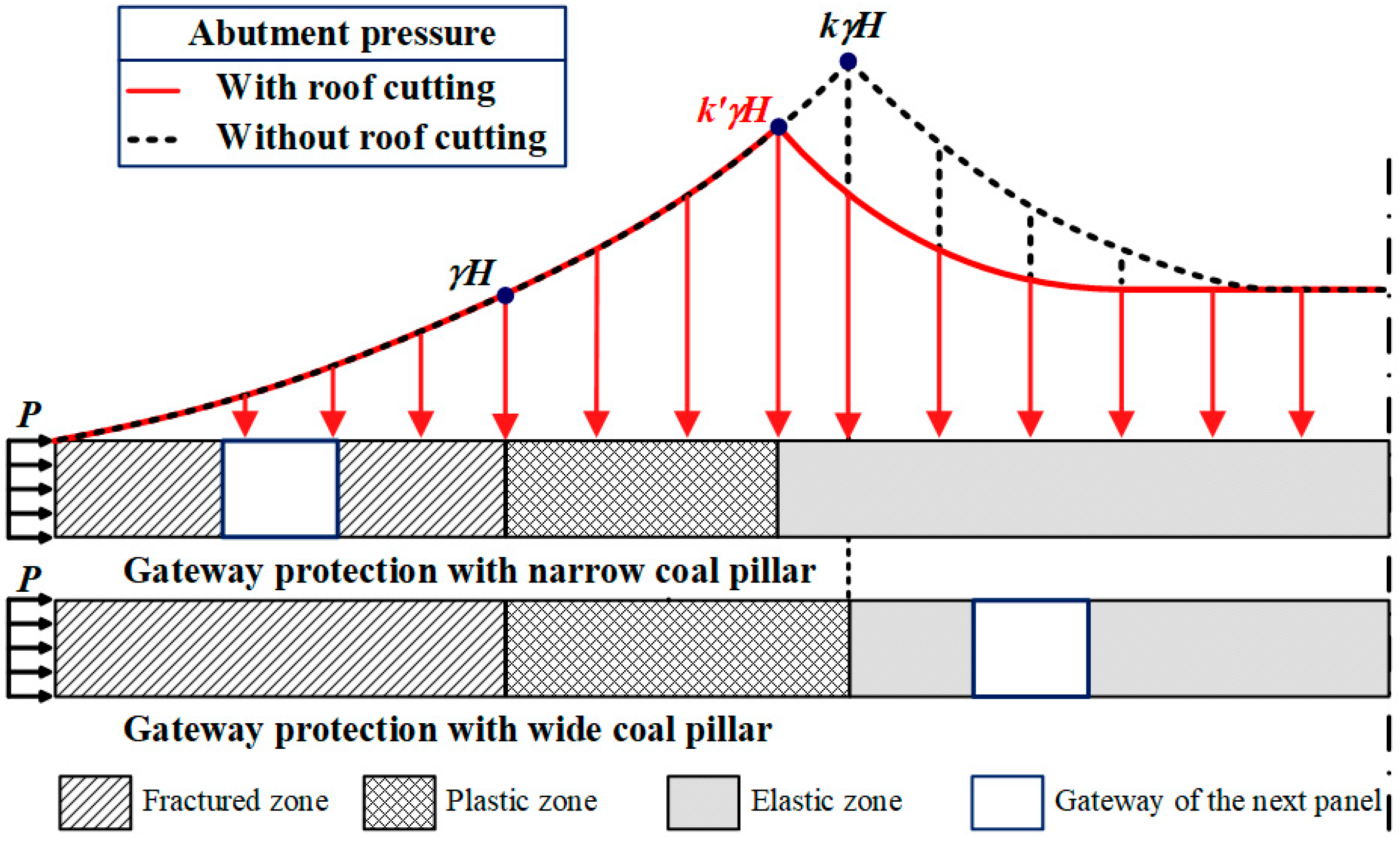
Figure 1. Abutment pressure distribution model of the pillar on the side of the gateway.
Buildings 15 03682 g001
Figure 2. Mechanical model of the coal pillar and its micro-unit: (a) Full narrow pillar; (b) micro-unit.
Buildings 15 03682 g002
Figure 3. Mechanical model of the cantilever beam of overlying roofs: (a) Characterization of step-shaped fractures in the cantilever structure [55]; (b) mechanical modeling of roof cantilever structure.
Buildings 15 03682 g003
Figure 4. Mechanical model of the i-th cantilever beam of single roof.
Buildings 15 03682 g004
Figure 5. Mechanical model of the cantilever beam with different failure modes: (a) In the first stage; (b) in the second stage.
Buildings 15 03682 g005
Figure 6. Engineering geological conditions of longwall panels 8311 and 8312: (a) Layout plan of longwall faces 8311 and 8312; (b) the lithology bar chart of rock layers; (c) diagram of location relation between gateways 2311 and 2312 (A-A section).
Buildings 15 03682 g006
Figure 7. The maximum design widths of the narrow pillar under different mining factors: (a) Mining height and burial depth; (b) mining height and support strength.
Buildings 15 03682 g007
Figure 8. Peak stress inside the pillar under different pillar widths and support strengths.
Buildings 15 03682 g008
Figure 9. The fracture length of the roof and the filling characteristics of the gob.
Buildings 15 03682 g009
Figure 10. The state function of different fracture stages in the roofs with the cutting angle: (a) In the first stage; (b) in the second stage.
Buildings 15 03682 g010
Figure 11. Numerical simulation model of gateway protection with the narrow coal pillar.
Buildings 15 03682 g011
Figure 12. Stress distribution of surrounding rock during mining of panel 8311: (a) Stress distribution of surrounding rock; (b) stress evolution of surrounding rock in gateway 2312.
Buildings 15 03682 g012
Figure 13. Flowchart of partition control of the surrounding rock stability.
Buildings 15 03682 g013
Figure 14. Technical plan for gateway protection with the narrow coal pillar: (a) Partition division in longwall panels; (b) diagram of roof pre-splitting, active and passive support; (c) cross-section diagram of gateways after reinforced support.
Buildings 15 03682 g014
Figure 15. Bolts and cables force monitoring during mining of panel 8311.
Buildings 15 03682 g015
Figure 16. Surrounding rock deformation monitoring in gateway 2312: (a) Diagram of surrounding rock deformation measurement station in gateway 2312; (b) surrounding rock deformation in gateway 2312 during the mining process of panel 8311.
Buildings 15 03682 g016
Table 1. Physical and mechanical parameters of coal and rock.
LithologicalDensity/kg·m−3Elastic Modulus/GPaPoisson’s RatioCohesion/MPaInternal Friction Angle/°Tensile Strength/MPa
mudstone24507.360.241.60301.6
medium-grained sandstone245025.370.207.26436.1
fine-grained sandstone251025.310.207.26436.1
siltstone250016.430.264.50435.9
fine-grained sandstone251025.310.207.26436.1
coal15002.000.321.44360.4
mudstone24507.360.241.60301.6
sandy mudstone23009.820.323.80404.4
Table 2. Strain-softening characteristics of coal.
Plastic shear strain00.050.11
Cohesion/MPa3.201.601.071.07
Internal friction angle/°25.020.017.017.0
Table 3. Simulation parameters of the caving zone.
Density/(kg·m−3)Elastic Modulus/GPaPoisson’s RatioCohesion/MPaInternal Friction Angle/°
190011.69.3204
Strain00.010.020.030.040.050.060.070.08
Stress/MPa01.182.53.985.677.599.8112.3915.45
Strain0.090.10.110.120.130.140.150.160.17
Stress/MPa19.1223.6129.2136.4246.0359.4979.67113.31180.59
Disclaimer/Publisher’s Note: The statements, opinions and data contained in all publications are solely those of the individual author(s) and contributor(s) and not of MDPI and/or the editor(s). MDPI and/or the editor(s) disclaim responsibility for any injury to people or property resulting from any ideas, methods, instructions or products referred to in the content.