Article

Mechanical Performance and Shrinkage Behavior of Ultrahigh-Performance Concrete with Ferronickel Slag Under Various Curing Conditions

1
R&D Team, Sales Division, ASIA CEMENT Co., Ltd., Yongin-si 17118, Republic of Korea
2
Department of Structural Engineering Research, Korea Institute of Civil Engineering and Building Technology, Goyang-si 10223, Republic of Korea
3
Korean Peninsula Infrastructure Research Center, Department of Construction Policy Research, Korea Institute of Civil Engineering and Building Technology, Goyang-si 10223, Republic of Korea
*
Author to whom correspondence should be addressed.
Buildings 2025, 15(20), 3670; https://doi.org/10.3390/buildings15203670
Submission received: 5 August 2025 / Revised: 28 September 2025 / Accepted: 5 October 2025 / Published: 12 October 2025
(This article belongs to the Section Building Materials, and Repair & Renovation)

Abstract

The main objective of this study was to evaluate the long-term mechanical performance and shrinkage behavior of ultrahigh-performance concrete (UHPC) in which the granulated ground blast-furnace slag (GGBFS), used as part of the binder, is replaced partially or fully with ferronickel slag (FNS). The aim was to identify potential strength reduction and expansion problems associated with the use of FNS powder. For steam-cured UHPC, the compressive strength of the FNS100 (124.8 MPa) was comparable to that of the control case (FNS0, 125.1 MPa), and the tensile strength showed only a 0.3 MPa difference. Under constant-temperature and constant-humidity conditions, all mixtures satisfied the design strength standard of 120 MPa by the end of the curing period. Considering constant-temperature and constant-humidity conditions, shrinkage evaluation revealed that the FNS100_NON_AD (no shrinkage-reducing and expansive agents) exhibited 3.8 times greater shrinkage compared to FNS0, while other mixtures remained within a narrow range. These results indicate that shrinkage was governed more by the presence and type of admixtures than by the FNS replacement rate itself. This study demonstrated that FNS has sufficient potential for use as a binder in UHPC and encourages further research to optimize admixture use for long-term durability and shrinkage control.

1. Introduction

Concrete is a highly economical construction material that is used globally in excess of 5.5 billion tons annually owing to its excellent mechanical and durability performance. However, it has disadvantages such as a low tensile strength compared to its compressive strength, high self-weight, and durability problems due to cracking [1]. In particular, because of these material properties, concrete structures inevitably develop cracks, which significantly reduce the durability of the structures against deterioration phenomena such as chloride attacks, carbonation, and freeze–thaw cycles, caused by the penetration of deteriorating substances [1,2,3,4]. These cracks are then advanced by external structural forces, further significantly reducing the durability performance of the concrete structures against chloride attacks and carbonation by facilitating the movement of moisture, chloride ions, and carbon dioxide [3,5,6,7].
To overcome these durability problems and improve the engineering performance of concrete structures, several research studies exploring a wide variety of solutions, such as the development of high-performance concrete (HPC) using ground granulated blast-furnace slag (GGBFS), fly ash (FA), and silica fume (SF) as binders; the exploration of alkali-activated cementitious materials from industrial byproducts; concrete surface repair through silicate impregnation; and the use of fiber-reinforced polymer (FRP) hybrid bars, have been conducted [8,9,10,11,12]. Particularly of note is ultrahigh-performance concrete (UHPC), which has been under active development worldwide since the early 2000s. UHPC is a high-performance fiber-reinforced cementitious composite that can achieve high compressive strengths of 80–180 MPa, higher than those of conventional concrete, through the use of different materials, mixtures, and curing methods and exhibits significantly enhanced tensile strength, ductility, and toughness owing to its incorporation of large amounts of steel fiber [13,14]. UHPC uses ordinary Portland cement (OPC) and SF as binders and is characterized by high fluidity, allowing it to self-consolidate. It has a highly dense internal pore structure owing to its use of micro materials, and surface cracking is suppressed by the use of steel fibers, resulting in excellent durability against external deterioration phenomena such as chloride attacks, carbonation, and freeze–thaw cycles [15,16]. Additionally, UHPC has a tensile strength approximately five times that of ordinary concrete, and thus, the structural design standards in South Korea consider the tensile strength of UHPC in their designs [17]. These excellent mechanical properties are being actively researched to reduce the cross-sectional dimensions and self-weight of structures for use in modular construction [18,19,20].
Generally, UHPC has a very low water–binder ratio (approximately 0.2) and does not use coarse aggregates, which raises concerns about cracking because of autogenous shrinkage at early ages, when tensile strength is weak. Cracks that occur at early ages can cause various performance deficiencies in structures, and thus, the appropriate use of shrinkage-reducing materials is essential when formulating UHPC [21,22]. Autogenous shrinkage refers to the phenomenon where the volume of concrete shrinks as a result of self-desiccation, which occurs as cement consumes the mixing water needed for the hydration reaction. Self-desiccation can be controlled by supplying moisture to the surface of the concrete during the initial curing, but in practice, it is difficult to implement during the construction of concrete structures [23]. Expansion materials such as shrinkage-reducing agents and expansive agents can compensate for the initial shrinkage caused by various factors by expanding the concrete. Calcium sulfoaluminate (CSA)-type expansion agents initially react to form ettringite, causing the concrete to expand, while shrinkage-reducing agents reduce the surface tension of pore water in the cement paste, thereby reducing autogenous shrinkage [24,25]. Furthermore, it is known that in UHPC with a high unit binder content, the proportion of autogenous shrinkage relative to the total shrinkage is higher compared to that in ordinary concrete [26]. Dry shrinkage of concrete occurs as a result of the evaporation of the mixing water present in capillary pores within the concrete. As the internal moisture decreases, the capillary stress increases, leading to internal shrinkage forces, a reduction in volume, and the formation of cracks [27]. Dry shrinkage also needs to be controlled and should be managed along with autogenous shrinkage to minimize the occurrence of initial cracks in the structure.
Ferronickel slag (FNS) is an industrial byproduct generated during the production of ferronickel alloys. Globally, several million tons of FNS are produced annually, with approximately 2 million tons generated each year in South Korea alone. Owing to this substantial generation and relatively low market price compared with ground granulated blast-furnace slag (GGBFS), FNS has attracted growing attention as a substitute resource to improve both the economic and environmental efficiency of concrete production. Previous studies have primarily focused on utilizing FNS as aggregate or as a supplementary cementitious material in conventional concrete, demonstrating its recycling potential [28,29,30,31,32]. Chemically, FNS is mainly composed of SiO2, MgO, Al2O3, and CaO, but its relatively high MgO content raises concerns of expansion due to the possible formation of brucite (Mg(OH)2) [33,34,35]. Nevertheless, other investigations have indicated that when Mg in FNS occurs predominantly as ferroan forsterite (Mg2SiO4), replacement of up to 65% of cement in ordinary concrete is possible without risks of expansion [36]. Despite these promising findings, research on the use of FNS in ultrahigh-performance concrete (UHPC) remains scarce. In particular, little is known about the long-term shrinkage behavior, mechanical performance under dry–wet cyclic conditions, and the combined effects of shrinkage-reducing and expansive admixtures in FNS-based UHPC.
The purpose of this study was to evaluate the long-term compressive and tensile strength and the shrinkage behavior of UHPC mixed with FNS powder to examine the feasibility of using FNS powder as a binder for UHPC. Additionally, the used FNS powder was examined via X-ray diffraction (XRD) and X-ray fluorescence (XRF) analyses to determine whether there are factors that could lead to expansion. In this study, the curing conditions for UHPC with FNS considered were steam curing, constant-temperature and constant-humidity curing, and dry–wet cyclic conditions. The mix proportions examined had four levels of FNS content: 0, 30, 50, and 100% FNS replacement rate (defined herein as the proportion of GGBFS replaced with FNS). Additionally, in cases where expansion occurs in the UHPC mixed with FNS, it may be possible to compensate for shrinkage with the expansion. Therefore, for the UHPC mix with 100% FNS replacement rate, cases where no expansion agent or shrinkage-reducing agent was used were also considered.
While the scope of this study has been defined above, it was also important to clarify its novelty in the existing literature. Previous studies have reported on the mechanical and durability properties of UHPC incorporating various industrial by-products, including ferronickel slag [31,32,35,36]. However, little research has addressed the shrinkage behavior of UHPC with FNS, particularly under long-term and dry–wet cyclic conditions [21,22,23,24,31,32,33,35,36]. The novelty of this study was in the evaluation of the shrinkage behavior of UHPC with partial and full replacement of GGBFS by FNS, considering both constant and dry–wet cyclic environments. This work thus filled an important gap in the previous literature and provides new insights for the practical use of FNS-based UHPC.

2. Materials and Methods

2.1. Characteristics of Binders Used

This study used OPC, SF, GGBFS, and FNS as binders for the UHPC. The chemical properties of these materials, as confirmed through XRF analysis, are shown in Table 1. The FNS powder was found to have a higher MgO content compared to that of the GGBFS powder, indicating that an examination for expansion is necessary. Because of the characteristics of the steel slag series, the Fe2O3 content was also found to be high. Furthermore, because the CaO content is lower than that of GGBFS, it is deemed necessary to compare the strength development behavior with that of concrete where only GGBFS is used. According to earlier research studies, the occurrence of expansion is determined by the form of Mg in the FNS [36], and thus, the FNS used in this study was subjected to XRD analysis and Rietveld quantitative analysis. The XRD analysis results are shown in Figure 1. Approximately 70% of the Mg in the FNS occurs in the form of stable Mg2SiO4, which is expected not to participate in hydration and not to be converted into brucite (Mg(OH)2), the Mg form that causes expansion in concrete [36]. Therefore, there should be no concern about expansion even if FNS is used in this study as a binder. Although the XRD results suggest that a major portion of MgO in FNS exists as crystalline Mg2SiO4, this interpretation is qualitative and does not account for the potential presence of MgO in the amorphous phase. Quantitative phase analysis, including Rietveld refinement and amorphous content determination, was not conducted in this study and was planned for future work. The XRD pattern of FNS exhibited sharp peaks at approximately 21.5°, 31.3°, and 36.1°, which were consistent with standard diffraction data for Mg2SiO4, suggesting its presence as a dominant crystalline phase. Additionally, other diffraction peaks observed at approximately 26.6°, 30.2°, 36.9°, 42.9°, and 62.3° (2θ) may correspond to mineral phases commonly reported in ferronickel slag. Specifically, the peak at 26.6° can be attributed to SiO2 (PDF# 46-1045), those at 30.2° and 36.9° to MgAl2O4 (PDF# 21-1152), and the peaks at 42.9° and 62.3° to MgO (PDF# 45-0946). These phase assignments were made with reference to standard JCPDS data, and any phases deemed mineralogically improbable or irrelevant to typical slag chemistry were deliberately excluded to ensure accurate interpretation. Note that only mineral phases geochemically relevant to ferronickel slag, such as Mg2SiO4, were considered in the interpretation. Other minor phases automatically suggested by the XRD software, including some rare-earth or unrelated compounds, were excluded to avoid misinterpretation. The particle shapes of the SF, GGBFS, and FNS used in this study were captured via scanning electron microscopy (SEM) and are shown in Figure 2. The particle shapes of the FNS and GGBFS powders were found to be similar. Although the particle size distribution was not measured directly, the surface area values in Table 1 and SEM images in Figure 2 provide a general indication of the particle fineness and morphology of the binder materials. Detailed particle size distribution analysis could be addressed in future studies.

2.2. UHPC Mixture Compositions

This study investigated the feasibility of using FNS powder as a binder in steel-fiber-reinforced UHPC mixtures, which have a strength of 120 MPa. In this mix, steel fibers (length = 19 mm) were used at a volume ratio of 1%, and test variables were considered based on replacing 0, 30, 50, and 100% of the GGBFS powder, typically used as part of the UHPC binder, with FNS powder. Additionally, to verify if the expansion resulting from the inclusion of FNS powder can compensate for the shrinkage of UHPC, an experimental variable was added to the FNS replacement rate of 100%, without the use of shrinkage-reducing or expansion agents. Table 2 shows the mixture compositions for each test case. The detailed mixing ratios could not be presented because of a patent on the relevant technology. The total premixing binder consisted of OPC, SF, GGBFS, FNS, and filler, with GGBFS accounting for approximately 11.3% of the total binder. Based on the total binder content, the mixture consists of approximately 64.52% OPC, 4.84% silica fume, 19.36% filler, and 11.29% combined slag materials (including both GGBFS and FNS). Of this 11.29% GGBFS, up to 100% was replaced with FNS. The UHPC was mixed using a high-speed planet mixer with a maximum rotational speed of 1000 rpm. First, the dry ingredients were dry-mixed at a low speed (500 rpm) for 5 min. Subsequently, water and a superplasticizer were added and blended at a high speed (1000 rpm) for a maximum of 10 min. Finally, steel fibers were added, and the mixture was blended for an additional 5 min. The engineering properties of the steel fibers used in the mix are shown in Table 3. The admixtures used in this study consisted of a polycarboxylate-based superplasticizer with a solid content of 25%, a shrinkage-reducing agent with a density of 3.18 g/cm3, and an expansive agent mainly composed of CaO-based compounds.

2.3. Specimen Preparation

This study evaluated the mechanical properties and shrinkage behavior of UHPC mixed with FNS powder, considering constant temperature and humidity and dry–wet cyclic conditions. For FNS0 and FNS100, a number of the samples were subjected to steam curing at 90 ± 2 °C for two days. The compressive and tensile strengths were tested to see if UHPC mixed with FNS could get stronger quickly.
For all UHPC formulations, a number of the samples were subjected to constant-temperature and constant-humidity curing at 23 ± 2 °C and a relative humidity (RH) of 50 ± 5%. Other samples were subjected to constant-temperature and constant-humidity curing (23 ± 2 °C, RH 50 ± 5%) until the age of 28 days, followed by repeated exposure to room-temperature drying and immersion in water, alternating at 7-day intervals, referred to hereafter as dry–wet cyclic conditions. During the dry–wet cyclic curing phase, all specimens were fully immersed in water during the wetting cycle. For the drying cycle, the specimens were exposed to laboratory air under controlled conditions of 23 ± 2 °C and 50 ± 5% relative humidity, consistent with the constant-temperature and constant-humidity curing environment. The 7-day dry–wet cycle was chosen because this period was expected to be sufficient for the specimens to become fully immersed and dried, and it was anticipated that this cycle would allow the observation of expansion or cracking induced by the dry–wet repetition.
For the shrinkage test, the total shrinkage was measured using air-dried exposed specimens, whereas the self-shrinkage was evaluated using specimens sealed with tape film. A tape-film sealing method was used to minimize moisture loss from the specimens during the shrinkage measurement period. While this method may not act as a completely impermeable barrier, it has been widely applied in similar shrinkage studies and is generally considered effective for maintaining adequate sealing within the tested time frame. Nevertheless, some minor limitations inherent to this method should be acknowledged for long-term curing durations [22,23,25,26]. Measurements during the shrinkage test were concluded upon confirmation that the strain converged to a certain value. For the samples subjected to dry exposure and for those in sealed packaging, the test was concluded upon confirmation of convergence to a certain value at 90 days. By contrast, for the samples subjected to dry–wet cyclic conditions, the test was concluded at 130 days. Table 4 summarizes the evaluation period, curing methods, and other details for each evaluation item (defined herein as the UHPC property or behavior evaluated or focused upon for the given samples).

2.4. Test Methods

2.4.1. Compressive and Tensile Strength Evaluation Method

The compressive strength of UHPC mixed with FNS powder was evaluated according to KS F 2405, in accordance with the exposure conditions and evaluation days outlined in Table 4. Direct tensile strength was evaluated according to the test method provided by the Korean Concrete Institute [17]. For each mixture and curing condition, five specimens (n = 5) were prepared and tested to evaluate the mechanical properties. The average values are presented in the figures, with error bars indicating the standard deviation. For the evaluation of the tensile strength, notches were made on both sides of the center of each specimen to induce direct tensile failure at that location. Photographs of the evaluation of compressive strength and direct tensile strength are shown in Figure 3.

2.4.2. Shrinkage Evaluation Method

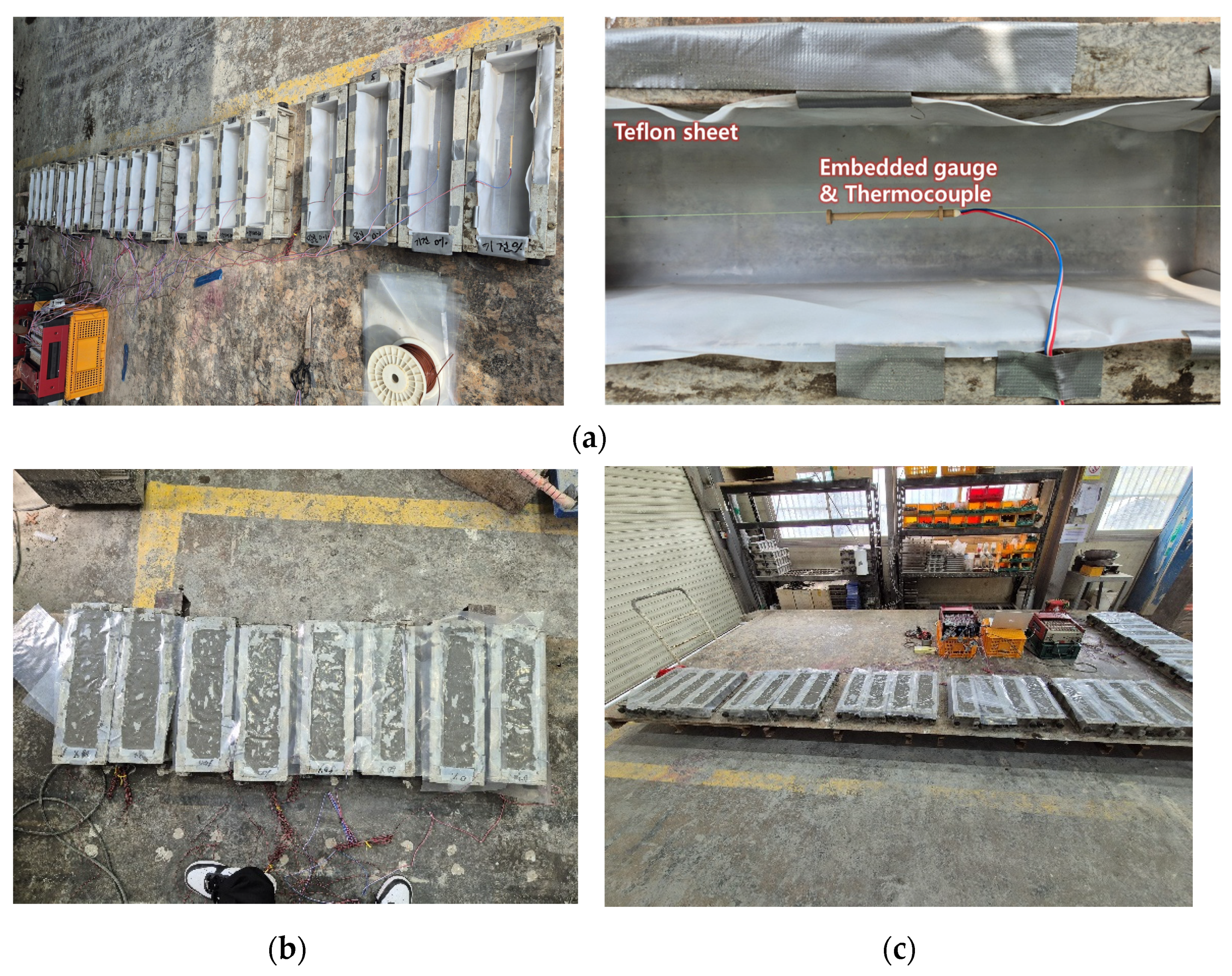
The shrinkage of UHPC mixed with FNS powder was measured according to KS F 2424. Figure 4a shows that during the production of the 100 mm × 100 mm × 400 mm prismatic specimens, an embedded gauge was placed at the center of each specimen, and shrinkage was measured at 10-min intervals. For the specimens used for the autogenous shrinkage evaluation, the entire specimen was sealed with tape film during concrete placement. By contrast, the specimens used for the dry shrinkage evaluation and those subjected to dry–wet cyclic conditions were not separately packaged. Therefore, the shrinkage measured for the specimens used for dry shrinkage evaluation was the total shrinkage, from which the autogenous shrinkage was then subtracted to yield the dry shrinkage value. On the other hand, for the specimens exposed to dry–wet cyclic conditions, only the total shrinkage was considered.

3. Performance Evaluation of UHPCs Subjected to Different Curing Conditions

3.1. Short-Term Performance Evaluation of UHPCs Subjected to Steam Curing

The evaluation results for the UHPCs, with and without FNS powder, subjected to steam curing (90 °C, 48 h) to induce rapid strength development, are shown in Figure 5. The UHPC formulations considered in this test were FNS0, i.e., the control, without any replacement of GGBFS with FNS powder; and FNS100, i.e., with 100% replacement of GGBFS with FNS powder. The compressive strengths of FNS0 (125.1 MPa) and FNS100 (124.8 MPa) exhibited a difference of 0.3 MPa. Similarly, the direct tensile strengths of FNS0 (9.3 MPa) and FNS100 (9.6 MPa) exhibited a difference of 0.3 MPa. Also, following the normalization of direct tensile strength by the square root of compressive strength, the results showed a value of 0.83 for FNS0 and 0.86 for FNS100. It has been reported in existing literature that UHPC under high-temperature steam curing for more than 48 h reaches its peak strength at the end of the curing period [37]. Each strength value shown in Figure 5 represents the average of five specimens. The COVs for compressive strength were 2.72% for FNS0 and 2.64% for FNS100, while the COVs for direct tensile strength were 0.83% and 0.86%, respectively. Therefore, for UHPCs subjected to steam curing, there is no problem with completely replacing GGBFS powder with FNS powder. Additionally, the slump flow was improved by approximately 14.7% from 680 mm to 780 mm by fully replacing GGBFS with FNS. Therefore, using FNS powder can improve the workability of the UHPC mixture.

3.2. Long-Term Mechanical Performance Evaluation of UHPCs Subjected to Constant-Temperature and Constant-Humidity Curing

3.2.1. Compressive Strength

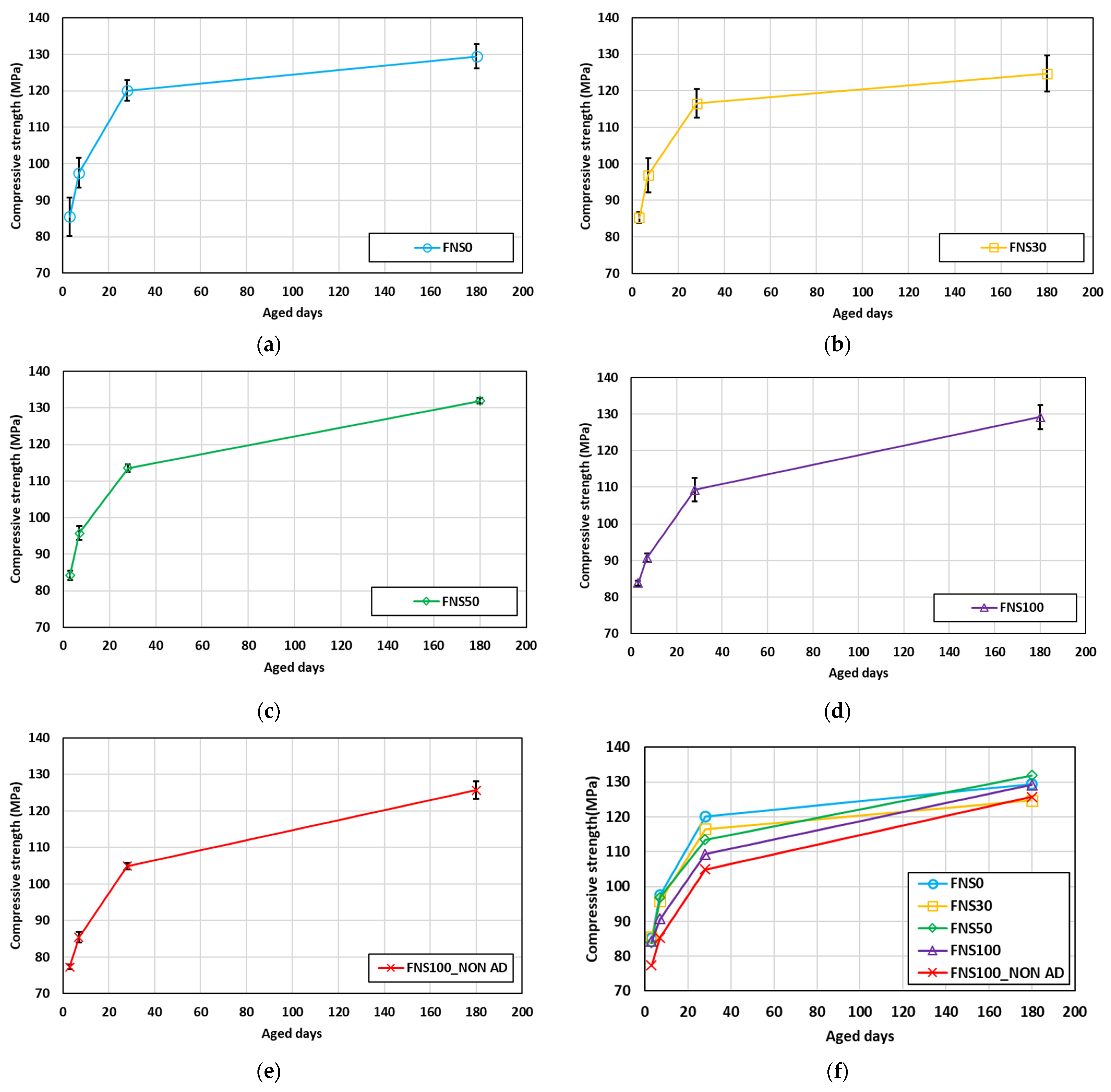
The compressive strength evaluation results for different UHPCs, with and without FNS powder, subjected to constant-temperature and constant-humidity curing (23 ± 2 °C, RH 50 ± 5%) for up to 180 days are shown in Figure 6.
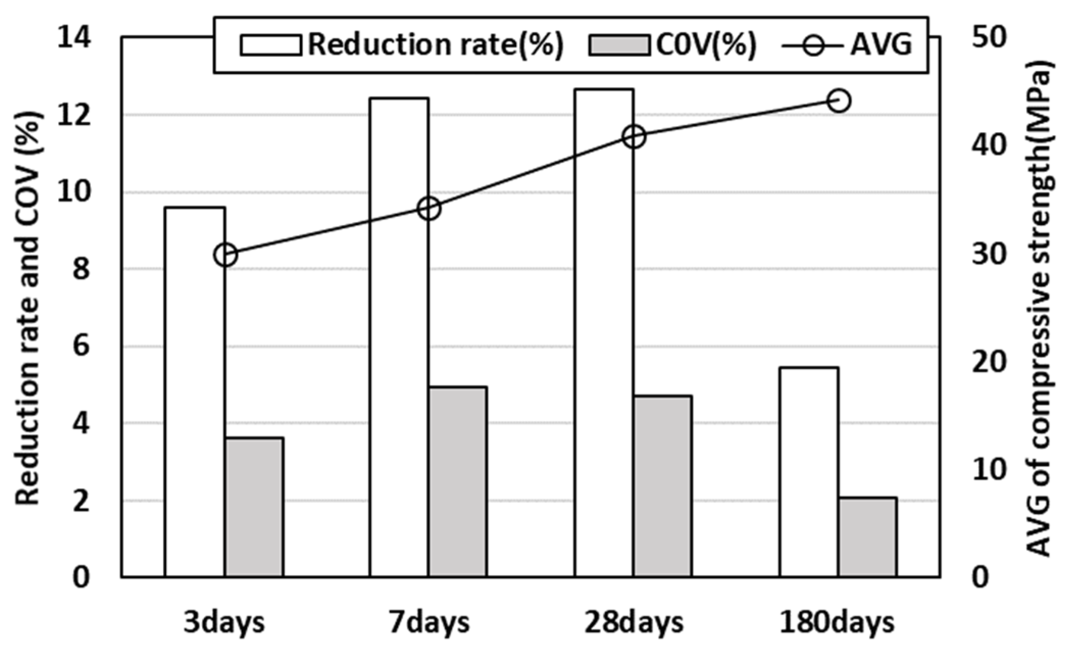
In the early curing period, from 3 to 28 days, a slight decrease in compressive strength was observed for higher addition rates of FNS powder. This is inferred to have been due to the lower CaO content of FNS powder compared to that of GGBFS, which contributes less to the promotion of the hydration reaction of OPC [31]. However, after a full curing period of 180 days, all mixtures satisfied the design strength criteria, and the variation in strength with the FNS replacement rate also significantly decreased. Compared to the steam curing results, there was no significant difference in the constant temperature and humidity curing test specimens of 180 aged days, with a difference of 4.3 MPa for FNS0 and 0.9 MPa for FNS100, which was consistent with existing research trend [37]. Figure 7 shows an analysis of the strength reduction rate and coefficient of variation (COV) according to the FNS replacement rate on each evaluated curing day. In the initial curing period, from 3 to 28 days, the rate of strength reduction due to FNS replacement was evaluated to be in the range of 9.6–12.7%, whereas after a full curing period of 180 days, the reduction rate was evaluated to be 5.5%. The variability due to FNS replacement also significantly decreased after 28 days of curing, suggesting that even with 100% FNS replacement, there are no problems with compressive strength development if either steam curing is performed or if the UHPC is subjected to curing for a sufficient amount of time.

3.2.2. Tensile Strength

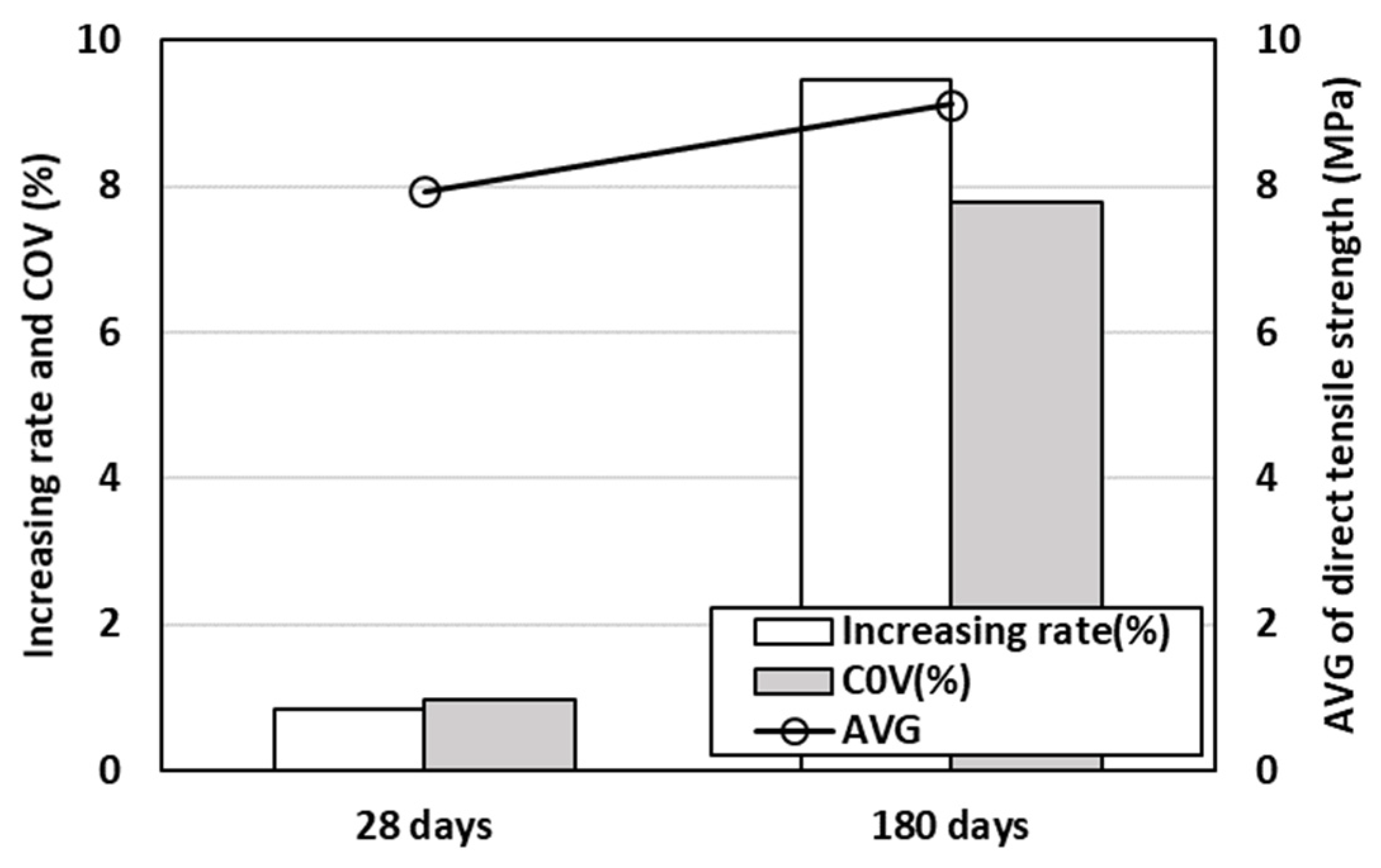
The direct tensile strength evaluation results for different UHPCs, with and without FNS powder, subjected to constant-temperature and constant-humidity curing (23 ± 2 °C, RH 50 ± 5%) are shown in Figure 8. The difference in direct tensile strength with respect to the rate of replacement with FNS powder was very small. In particular, at 180 days of curing, the FNS100_NON AD mix, which did not use any expansion agents or shrinkage-reducing agents, exhibited the highest tensile strength, with a 10% increase compared to that for the control FNS0. This is inferred to have been due to the increased curing period of the concrete without the use of shrinkage-reducing agents and expansion agents, which enhanced the adhesion strength between the concrete matrix and steel fibers as a result of the shrinkage that occurred. These results can be further analyzed based on the shrinkage analysis results discussed in Section 4. With the exception of the FNS100 NON AD mix, which did not contain any shrinkage-reducing or expansive agents, all specimens showed a tensile strength increase of up to 20% from 28 to 180 days. This progressive strength gain at later ages was attributed to several key mechanisms. The long-term hydration of reactive components such as silica fume, GGBFS, and FNS contributed to the progressive densification of the pore structure, as highlighted in a previous study [38]. In addition, the FNS particles themselves acted as a micro-filler, improving the overall packing density of the matrix. This physical effect enhanced the strength and integrity of the cementitious paste, which was crucial for tensile performance. Upon normalizing the direct tensile strength by the square root of the compressive strength, the normalized value was found to increase with the FNS replacement rate. Specifically, the FNS100 specimen showed a higher normalized value than FNS0. When comparing the tensile strength results of FNS0 and FNS100 specimens under steam curing and constant temperature and humidity curing, there was no significant difference, with a difference of 0.3–0.5 MPa, which was consistent with existing research trends [37]. Figure 9 shows an analysis of the variability of tensile strength with respect to the FNS addition rate for different curing durations. On day 28, despite the increase in the FNS replacement rate, a low COV and strength improvement rate were observed, but on day 180, these values significantly increased. This was due to the high tensile strength improvement rate for the FNS100_NON AD mix; when the FNS100_NON AD mix was excluded, the average value of direct tensile strength was 8.9 MPa, COV was 6.2%, and the tensile strength increase rate was 2.6%.

3.3. Long-Term Mechanical Performance Evaluation of UHPCs Subjected to Dry–Wet Cyclic Conditions After Curing

3.3.1. Compressive Strength

This section presents an analysis of the long-term compressive strength evaluation results for different UHPCs, with and without FNS powder, subjected after 28 days of curing to dry–wet cyclic conditions alternating at 7-day intervals. Generally, dry–wet cyclic conditions are known to make concrete susceptible to shrinkage and expansion owing to the movement of moisture [39,40]. In the case of concrete mixed with FNS powder, expansion can occur as a result of the formation of the expansive hydrate Mg(OH)2 [34]. Figure 10 shows the long-term compressive strength evaluation results for UHPC, with and without FNS powder, subjected to dry–wet cyclic conditions.
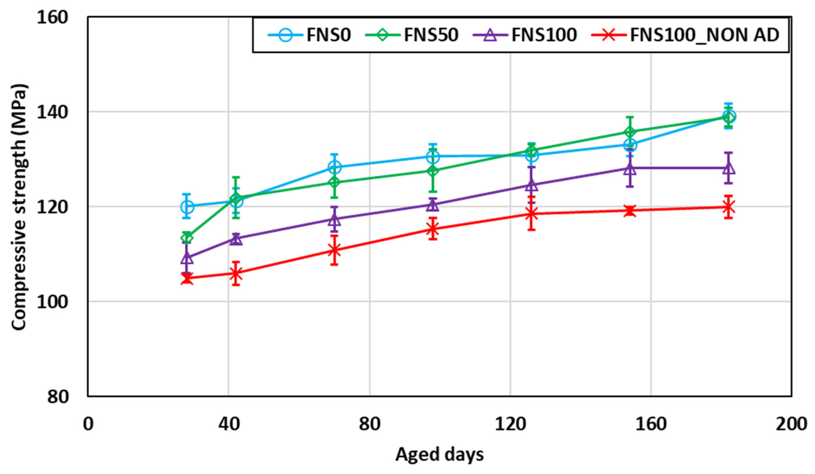
In FNS50, there was almost no difference in strength compared to that of FNS0 (control); however, in FNS100, a strength reduction of 8.3–14.8% compared to that of FNS0 was observed. This difference in strength was maintained at a consistent level despite the increase in curing duration. The reduction in compressive strength observed in the FNS100 was attributed to the lower latent hydraulic reactivity of ferronickel slag compared with GGBFS. While GGBFS contained a high amorphous content and sufficient CaO that promoted the formation of C–S–H gel, FNS is dominated by crystalline phases such as Mg2SiO4 and exhibits a higher Fe2O3 content with lower CaO availability. As a result, FNS participated less actively in hydration, leading to limited gel formation. These mineralogical differences hindered pore refinement and microstructural densification. Additionally, similar to the specimens subjected to constant-temperature and constant-humidity curing, all UHPCs for all conditions satisfied the design strength criteria. For the UHPCs mixed with FNS powder, there were no occurrences of strength reduction resulting from exposure to dry–wet cyclic conditions.
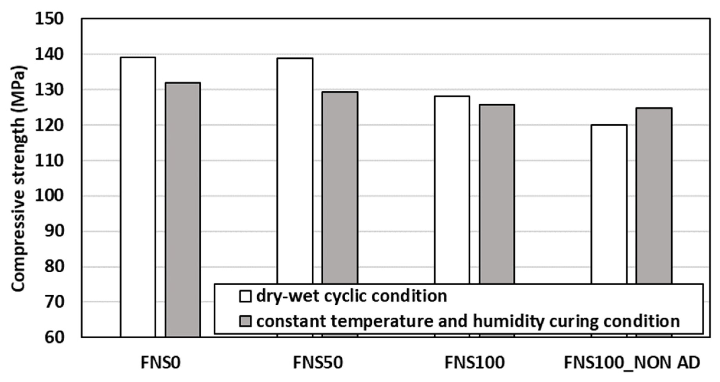
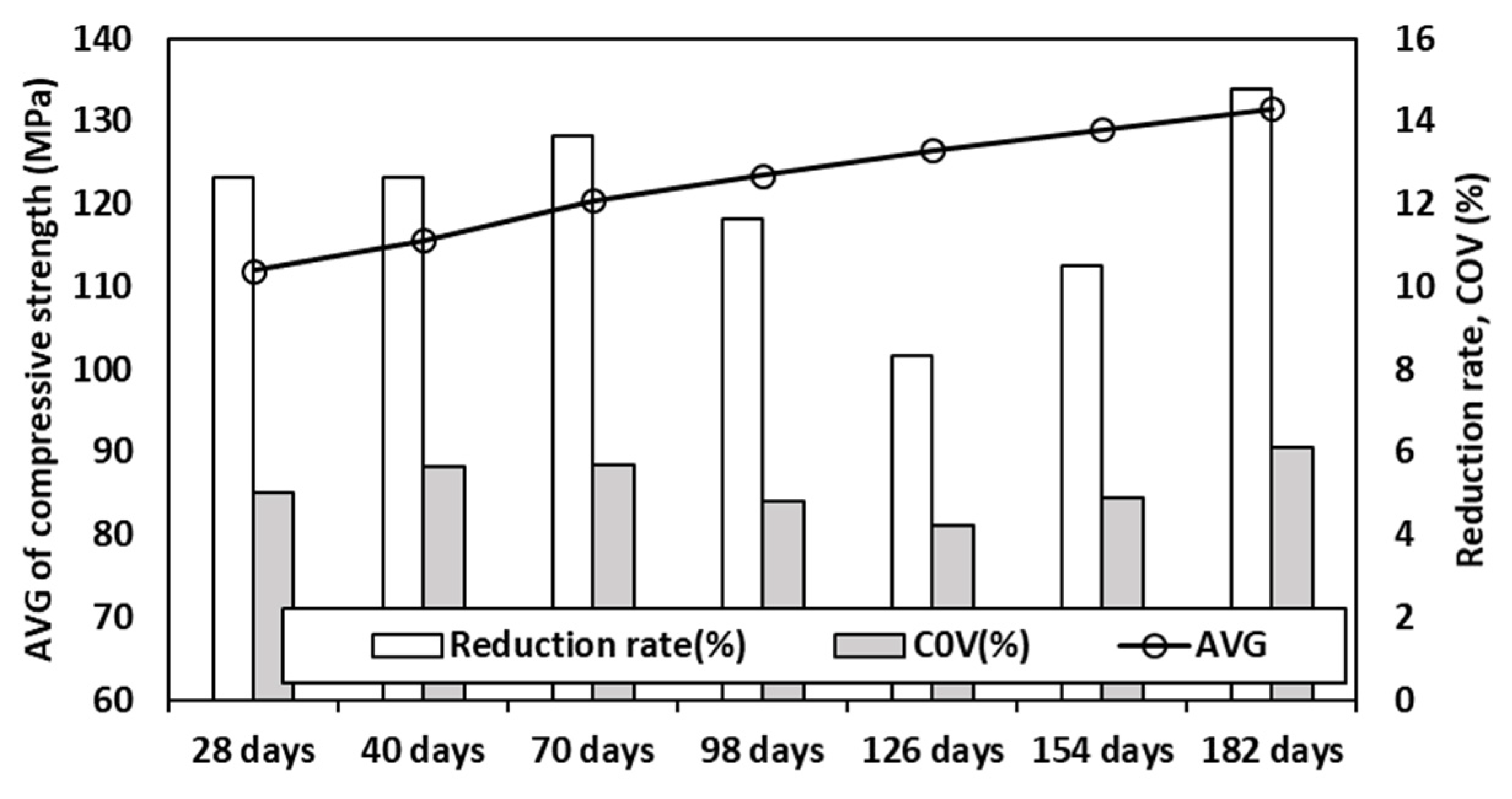
A comparison of strength between the specimens subjected to constant-temperature and constant-humidity curing and those subjected to dry–wet cyclic conditions, based on measurements obtained on the final curing day, is shown in Figure 11. For FNS0, FNS50, and FNS100, the specimens subjected to dry–wet cyclic conditions exhibited 2–7% higher strengths compared to those subjected only to the constant-temperature and constant-humidity curing. For FNS100_NON AD, the compressive strength after curing under constant-temperature and constant-humidity conditions was evaluated to be 3.8% higher than that under dry–wet cyclic conditions. The absence of expansion agents and admixtures resulted in less formation of additional ettringite, whereas the micro-matrix structure was weakened as a result of the shrinkage and expansion caused by the dry–wet cycle. Figure 12 shows the compressive strength reduction rates and COVs resulting from the addition of FNS for specimens exposed to dry–wet cyclic conditions over different lengths of time. As the dry–wet cyclic curing period increased, the strength reduction rates and COVs between mixes remained at similar levels without significant changes.

3.3.2. Tensile Strength

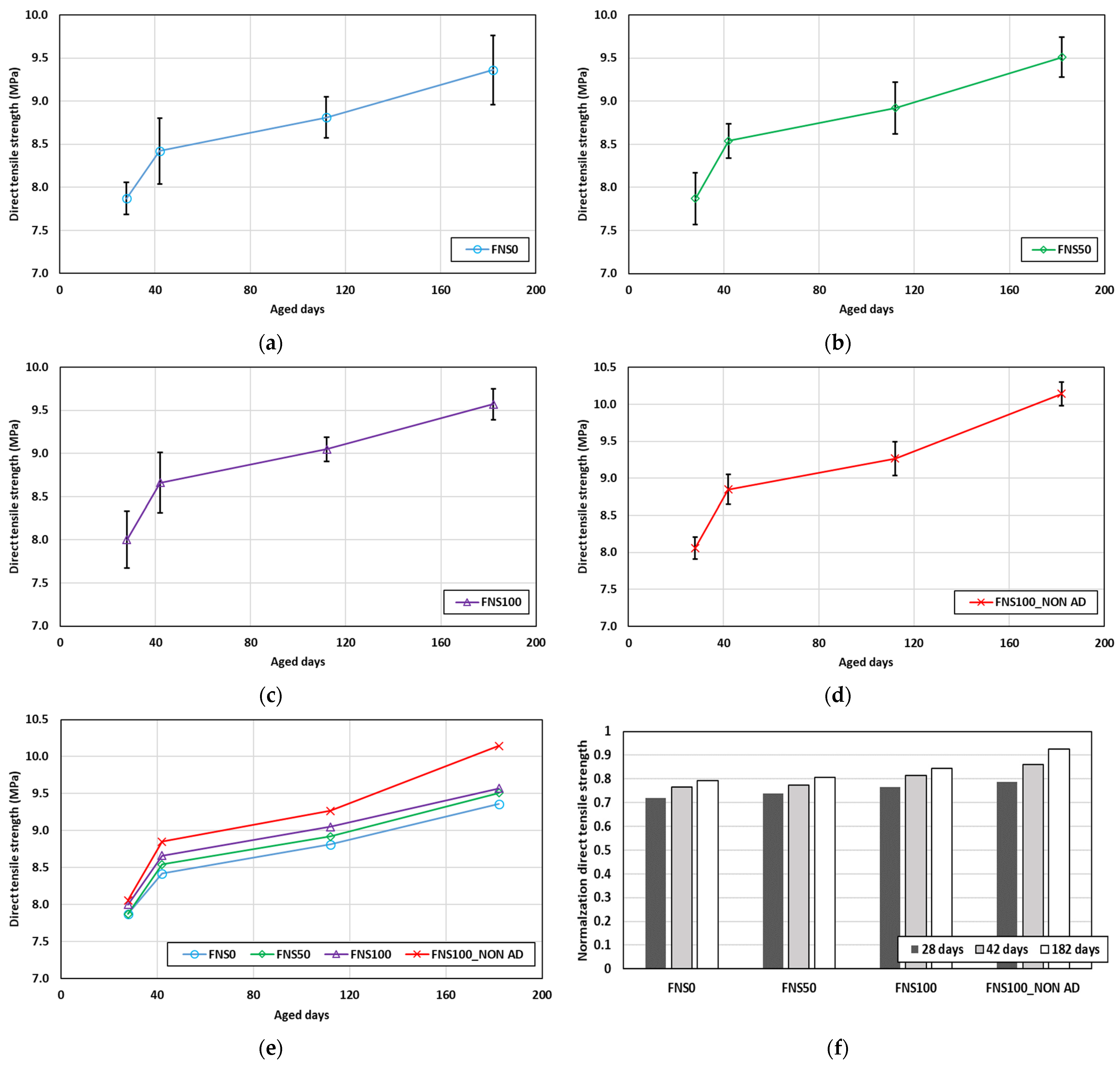
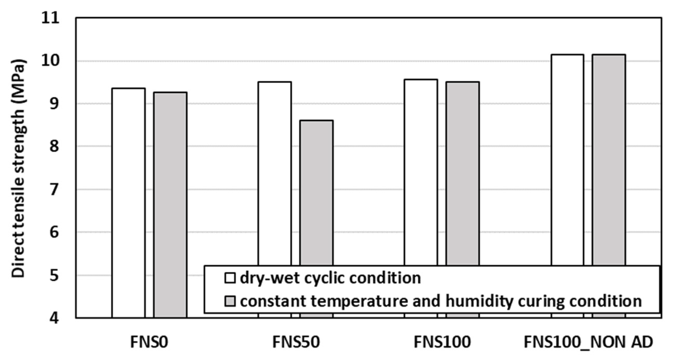
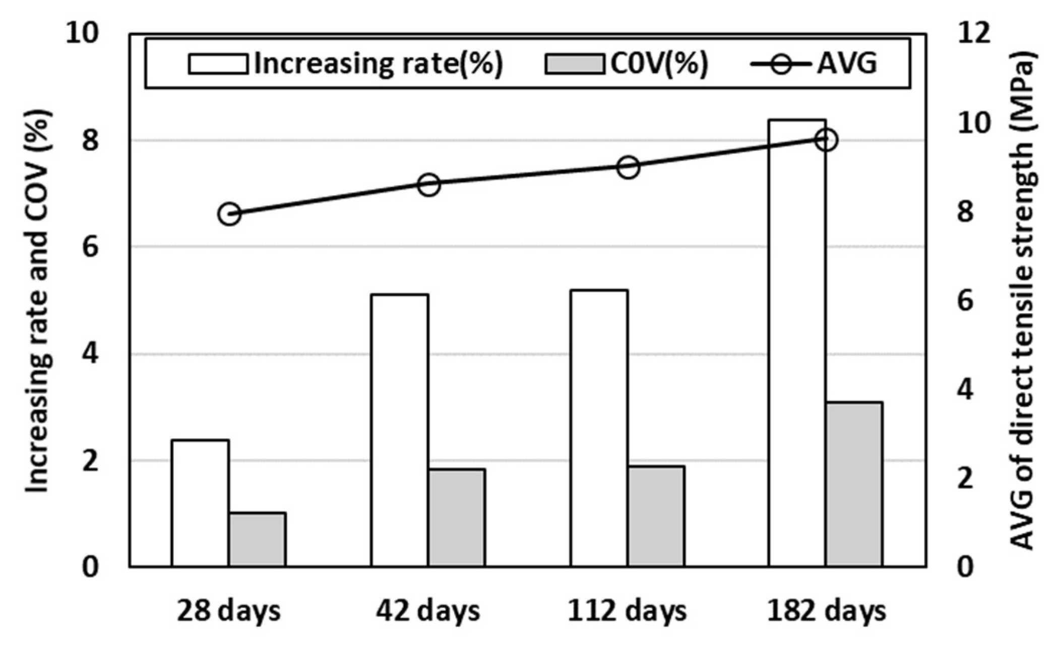
Figure 13 shows the direct tensile strength evaluation of different UHPCs (FNS0, FNS50, and FNS100) subjected after 28 days of curing to dry–wet cyclic conditions alternating at 7-day intervals. The differences in tensile strength between FNS0, FNS50, and FNS100 were evaluated to be minimal. For the specimens subjected to dry exposure conditions, the highest tensile strength was exhibited by the FNS100_NON AD formulation. This result suggests that the amount of expansion agent and shrinkage-reducing agent used has a dominant effect on the tensile strength behavior. The tensile strength also did not exhibit any decreases attributable to the dry–wet cyclic condition. Following the normalization of tensile strength by the square root of compressive strength, the normalized value slightly increased as the FNS replacement rate went up. This indicated that even with FNS, there were no issues with the development of UHPC’s direct tensile strength under wet-dry cycling conditions. A comparison of strength between the specimens subjected to constant-temperature and constant-humidity curing with those subjected to dry–wet cyclic conditions, based on measurements obtained on the final curing day, is shown in Figure 14. Excluding FNS50, the tensile strengths measured for the two curing conditions exhibited a difference of approximately 0.6–1%, suggesting that the difference in curing conditions does not significantly affect the tensile strength behavior of FNS UHPC. For FNS50, a 10% difference in strength was observed as an effect of the curing conditions, which was considered a test error. The variability of tensile strength was analyzed with respect to the FNS powder addition rate and curing duration, as shown in Figure 15. The average value and COV of the strengths of the specimens showed an increasing trend as the number of curing days increased. This variation was due to the high level of strength increase observed between 112 days and 182 days for the FNS100_NON AD mix, which did not use any expansion agent or shrinkage-reducing agent.

4. Expansion Evaluation of UHPCs Subjected to Different Curing Methods

4.1. Constant-Temperature and Constant-Humidity Condition

This section presents an analysis of the shrinkage behaviors of different UHPCs with and without FNS powder. Under constant-temperature and constant-humidity curing conditions (23 ± 2 °C, RH 50 ± 5%), the shrinkage of specimens sealed entirely with tape film during casting was considered as autogenous shrinkage, whereas the shrinkage of specimens exposed to air was considered as total shrinkage. The value obtained by subtracting the autogenous shrinkage from the total shrinkage was considered as the dry shrinkage value. The total shrinkage change rates for the dry shrinkage and autogenous shrinkage of different UHPCs with and without FNS powder are shown in Figure 16.
As the FNS replacement rate was increased, there were no significant changes in the dry shrinkage and autogenous shrinkage, and both exhibited similar values by the 90-day mark. Both autogenous shrinkage and dry shrinkage occurred mainly in the early stages of curing. In FNS100_NON AD, formulated without the use of shrinkage-reducing agent and expansion agent, autogenous shrinkage occurred after 30 days of curing, whereas dry shrinkage showed a tendency to continue. Additionally, no expansion attributable to the addition of FNS occurred. Autogenous shrinkage accounted for approximately 48.5% of the total shrinkage in FNS0, approximately 38.9% in FNS30 and FNS50, approximately 40% in FNS100, and approximately 65.0% in FNS100_NON AD. Ultimately, with regard to their total shrinkages at 90 days, FNS0, FNS30, FNS50, and FNS100 exhibited a range of values of −250.5 to −307.6, indicating no significant differences. However, for the FNS100_NON AD mix, a maximum shrinkage of 3.8 times, corresponding to a value of −957, occurred. The FNS used in this study was composed of stable Mg2SiO4, as indicated by the XRF and XRD analysis results in Section 2.1, and is considered not to have caused any expansion [33,36]. It can be inferred from these observations that even for UHPCs that contain FNS, the shrinkage behavior is dominated by the use of expansion agents and shrinkage-reducing agents.

4.2. Dry–Wet Cyclic Condition

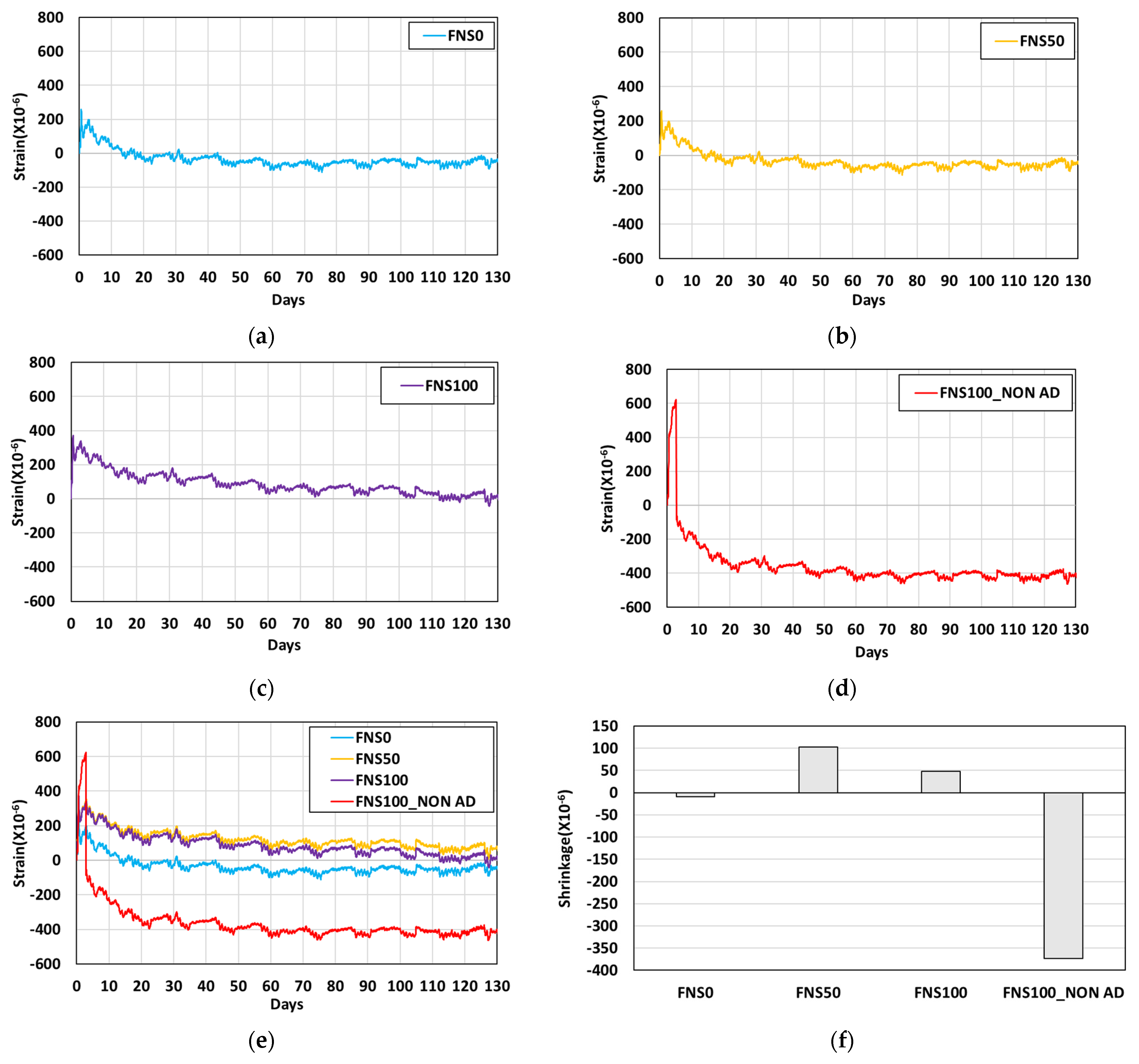
This section presents an analysis of the shrinkage behaviors of different UHPCs, with and without FNS powder, subjected to dry–wet cyclic conditions after 28 days of casting. In the analysis of the results for the dry–wet cyclic conditions, the total shrinkage was considered without distinguishing between dry and autogenous shrinkage. The shrinkage evaluation results for four mixes, i.e., FNS0, FNS50, FNS100, and FNS100_NON AD, over a period of 130 days after casting are shown in Figure 17.
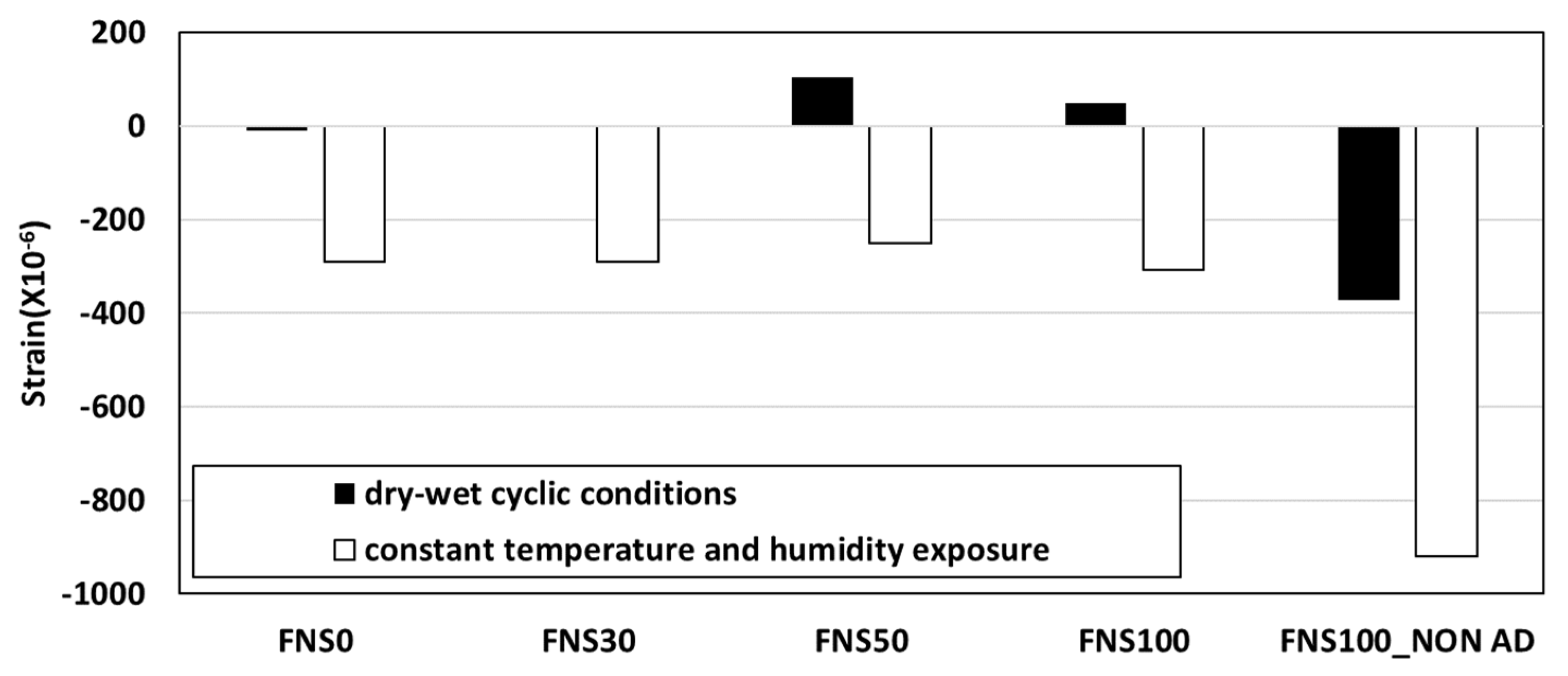
Compared to the results discussed in Section 4.1, regarding the specimens subjected to curing conditions where the temperature and humidity stayed the same, the specimens subjected to dry–wet cyclic conditions exhibited greater strain with respect to the FNS replacement rate. However, the use of FNS did not lead to any expansion. Compared to the control FNS0, slight expansions occurred in FNS50 and FNS100 but were not considered a significant concern. Additionally, as a result of the dry–wet cyclic condition, all mixtures underwent repeated expansion due to wetting and contraction due to drying; however, after 20 days of curing, they repeated a consistent pattern that converged to a certain level. Even in the dry–wet cyclic condition, the shrinkage behavior of UHPC mixed with FNS powder seems to be predominantly influenced by the use of admixtures. The expansion of the FNS50 and FNS100 mixes can be kept at the same level as that of the control mix (FNS0) by controlling the amounts of admixtures and shrinkage-reducing agents used. Figure 18 shows a comparison of total shrinkage at the final evaluation point between the specimens subjected to dry–wet cyclic conditions and those subjected to constant-temperature and constant-humidity conditions. When the dry–wet cyclic conditions were applied, the shrinkage decreased compared to that observed for the constant-temperature and constant-humidity conditions. However, the same trend was observed for FNS0, suggesting that this decrease in shrinkage was not due to the addition of FNS. Even when FNS powder was used for the UHPC binder, there was no occurrence of any expansion that would have been a cause for concern, and, in any case, such an expansion can be controlled by adjusting the amount of expansion agent and shrinkage-reducing agent. In future research studies, the amount of expansion agent and shrinkage-reducing agent should be tested as variables to further examine the feasibility of using FNS powder as a binder in UHPC.

5. Conclusions

This study evaluated the mechanical properties and shrinkage behaviors of ultrahigh-performance concrete (UHPC) in which ground granulated blast-furnace slag (GGBFS) was replaced by ferronickel slag (FNS) under various curing conditions. The main conclusions of this study are as follows.
1.
As a result of compressive and direct tensile strength evaluations of specimens subjected to 48-h steam curing, it was determined that FNS100 (100% GGBFS replacement with FNS) had compressive and direct tensile strengths equivalent to those of FNS0. Furthermore, FNS100 exhibited a 14.7% increase in flow compared to FNS0, indicating improved workability.
2.
Mechanical property evaluations under constant-temperature and constant-humidity curing revealed a slight decrease in compressive strength during the initial curing period with higher FNS replacement rates. However, by 180 days, all mixes satisfied the design strength criteria, and strength variability with FNS replacement decreased. Direct tensile strength showed minimal variation (COV < 1%) at 28 days but significantly increased to 6.2% by 180 days. This increase was primarily due to a significant tensile strength gain in FNS100_NON AD, which lacked expansion or shrinkage-reducing agents.
3.
For specimens subjected to dry–wet cyclic curing, compressive strength evaluations showed a maximum reduction of 14.8% due to FNS incorporation. However, excluding FNS100_NON AD, all UHPC formulations met the design strength criteria after 98 days. Conversely, increased FNS replacement rates resulted in minimal differences in direct tensile strength. Notably, among specimens under constant-temperature and constant-humidity curing, FNS100_NON AD exhibited the highest strength levels.
4.
Long-term shrinkage analysis showed minimal changes in drying and autogenous shrinkage with respect to FNS replacement, likely due to FNS’s stable Mg2SiO4 form. At 90 days, excluding FNS100_NON AD (which exhibited 3.8 times FNS0’s shrinkage, or −957), other UHPC mixes had similar total shrinkage values ranging from −259 to −307.6. Under dry–wet cyclic conditions, specimens experienced consistent volume expansion and contraction patterns, converging to a stable level. No expansion was observed from FNS incorporation as a UHPC binder, confirming that shrinkage can be effectively controlled by expansion and shrinkage-reducing agents.
5.
The results of this study demonstrated that the full (100%) replacement of GGBFS with FNS powder did not compromise the overall performance of UHPC. The FNS100 mix met the design strength criteria and exhibited favorable long-term mechanical properties under various curing conditions. This finding suggested that a 100% FNS replacement can be considered an optimal and practical mix design for achieving both high performance and environmental benefits. However, this study was limited to a single type of FNS powder and a fixed binder formulation, without considering variability in FNS composition or particle fineness. Future research should explore the influence of different FNS sources, optimize admixture dosages for shrinkage mitigation, and evaluate long-term durability performance—such as chloride resistance and freeze–thaw behavior—in various environmental exposures.

Author Contributions

Conceptualization, G.-S.R.; methodology, G.-S.R.; validation, G.-S.R., Y.-S.Y., and G.-H.A.; formal analysis, G.-S.R. and Y.-S.Y.; investigation, Y.-S.Y.; resources, K.-T.K. and G.-S.R.; data curation, G.-H.A.; writing—original draft preparation, Y.-S.Y. and G.-S.R.; writing—review and editing, G.-S.R. and Y.-S.Y.; visualization, Y.-S.Y. and G.-S.R.; supervision, K.-T.K.; project administration, G.-S.R.; funding acquisition, K.-T.K. and G.-S.R. All authors have read and agreed to the published version of the manuscript.

Funding

Research for this paper was carried out under the KICT Research Program (20250205-001, Development of Repair & Retrofit and Emergency Rehabilitation Technology using Customized SUPER Concrete for Existing Bridges in ASEAN Countries) funded by the Ministry of Science and ICT.

Data Availability Statement

The original contributions in this study are included in the article, and further inquiries can be directed to the corresponding authors.

Conflicts of Interest

Author Yong-Sik Yoon was employed by the company ASIA CEMENT Co., Ltd. The remaining authors declare that the research was conducted in the absence of any commercial or financial relationships that could be construed as a potential conflict of interest.

Abbreviations

The following abbreviations are used in this manuscript:
COVCoefficient of variation
CSACalcium sulfoaluminate
FAFly ash
FNSFerronickel slag
FRPFiber-reinforced polymer
GGBFSGround granulated blast-furnace slag
HPCHigh-performance concrete
OPCOrdinary Portland cement
RHRelative humidity
SEMScanning electron microscopy
SFSilica fume
UHPCUltrahigh-performance concrete
XRDX-ray diffraction
XRFX-ray fluorescence

References

  1. KCI (Korea Concrete Institute). Advanced Concrete Engineering; Kimoondang: Seoul, Republic of Korea, 2024. [Google Scholar]
  2. Huang, H.; Zou, L.; Liu, J.; Xie, X. Shrinkage Control and Durability of UHPC Using Mineral Admixtures and Internal Curing Materials. Buildings 2024, 15, 565. [Google Scholar]
  3. Jung, S.H.; Ryu, H.S.; Karthick, S.; Kwon, S.J. Time and crack effect on chloride diffusion for concrete with fly ash. Int. J. Concr. Struct. Mater. 2018, 12, 14. [Google Scholar] [CrossRef]
  4. Song, H.W.; Cho, H.J.; Park, S.S.; Byun, K.J.; Maekawa, K. Early-age cracking resistance evaluation of concrete structure. Concr. Sci. Eng. 2001, 3, 62–72. [Google Scholar]
  5. Yang, K.H.; Mun, J.H.; Yoon, Y.S. Effects of loading conditions and cold joint on service life against chloride ingress. Comput. Concr. 2018, 22, 319–326. [Google Scholar]
  6. Koh, T.-H.; Kim, M.-K.; Yang, K.-H.; Yoon, Y.-S.; Kwon, S.-J. Service life evaluation of RC T-girder under carbonation considering cold joint and loading effects. Constr. Build. Mater. 2019, 226, 106–116. [Google Scholar] [CrossRef]
  7. Gérard, B.; Marchand, J. Influence of cracking on the diffusion properties of cement-based materials: Part I: Influence of continuous cracks on the steady-state regime. Cem. Concr. Res. 2000, 30, 37–43. [Google Scholar] [CrossRef]
  8. Yoon, Y.S.; Kwon, S.J.; Kim, K.C.; Kim, Y.; Koh, K.T.; Choi, W.Y.; Lim, K.M. Evaluation of durability performance for chloride ingress considering long-term aged GGBFS and FA concrete and analysis of the relationship between concrete mixture characteristic and passed charge using machine learning algorithm. Materials 2023, 16, 7459. [Google Scholar] [CrossRef]
  9. Muthulingam, S.; Rao, B.N. Chloride binding and time-dependent surface chloride content models for fly ash. Front. Struct. Civ. Eng. 2016, 10, 112–120. [Google Scholar] [CrossRef]
  10. Guo, K.; Dong, H.; Zhang, J.; Zhang, L.; Li, Z. Experimental Study of Alkali-Activated Cementitious Materials Using Thermally Activated Red Mud: Effect of the Si/Al Ratio on Fresh and Mechanical Properties. Buildings 2025, 15, 565. [Google Scholar] [CrossRef]
  11. Kim, H.J.; Yoon, Y.S.; Yang, K.H.; Kwon, S.J. Durability and purification performance of concrete impregnated with silicate and sprayed with photocatalytic TiO2. Constr. Build. Mater. 2019, 199, 106–114. [Google Scholar] [CrossRef]
  12. Oh, K.S.; Park, K.T.; Kwon, S.J. Evaluation of anti-corrosion performance of FRP hybrid bar with notch in GGBFS concrete. J. Korea Inst. Struct. Maint. Insp. 2016, 20, 51–58. [Google Scholar] [CrossRef]
  13. Silva, M.L.D.; Prado, L.P.; Félix, E.F.; Sousa, A.M.D.D.; Aquino, D.P. The influence of materials on the mechanical properties of ultra-high-performance concrete (UHPC): A literature review. Materials 2024, 17, 1801. [Google Scholar] [CrossRef]
  14. Kravanja, G.; Mumtaz, A.R.; Kravanja, S. A comprehensive review of the advances, manufacturing, properties, innovations, environmental impact and applications of ultra-high-performance concrete (UHPC). Buildings 2024, 14, 382. [Google Scholar] [CrossRef]
  15. Graybeal, A.G. Material Property Characterization of Ultra-High Performance Concrete; Technical Report (FHWA-HRT-06-103); Federal Highway Administration: McLean, VA, USA, 2006. [Google Scholar]
  16. Abbas, S.M.L.N.; Nehdi, M.L.; Saleem, M.A. Ultra-high performance concrete: Mechanical performance, durability, sustainability and implementation challenges. Int. J. Concr. Struct. Mater. 2016, 10, 271–295. [Google Scholar] [CrossRef]
  17. KCI. The Structural Design Guidelines of Fiber Reinforced SUPER Concrete; Korea Concrete Institute: Seoul, Republic of Korea, 2019. [Google Scholar]
  18. Yang, Y.; Chen, B.; Chen, Y.; Zhou, H.; Liu, F.; Xie, X.; Chen, J.; Guo, W.; Wang, H. Performances of concrete columns with modular UHPC permanent formworks under axial load. Int. J. Concr. Struct. Mater. 2023, 17, 38. [Google Scholar] [CrossRef]
  19. He, Q.F.; Zou, J.M.; Zhang, C.F.; Zhong, Y.; Li, J.S.; Yi, W.J. Experimental study on the seismic performance of two-storey UHPC modular building structure. J. Build. Eng. 2024, 97, 110966. [Google Scholar] [CrossRef]
  20. Kim, K.C.; Yoon, Y.S.; Ryu, G.S.; Koh, K.T.; Lim, K.M. Performance evaluation of architectural modular member with ultra-high-performance fiber-reinforced concrete for application. Appl. Sci. 2024, 14, 2269. [Google Scholar] [CrossRef]
  21. Huang, H.; Ye, G. Examining the “time-zero” of autogenous shrinkage in high/ultra-high performance cement pastes. Cem. Concr. Res. 2017, 97, 107–114. [Google Scholar] [CrossRef]
  22. Shen, P.; Lu, L.; He, Y.; Rao, M.; Fu, Z.; Wang, F.; Hu, S. Experimental investigation on the autogenous shrinkage of steam cured ultra-high performance concrete. Constr. Build. Mater. 2018, 162, 512–522. [Google Scholar] [CrossRef]
  23. Kim, S.W.; Choi, S.; Lee, K.M.; Park, J.J. Autogeneous shrinkage characteristics of ultra high performance concrete. J. Korea Concr. Inst. 2011, 23, 295–301. [Google Scholar] [CrossRef]
  24. Shen, P.; Lu, L.; He, Y.; Wang, F.; Lu, J.; Zheng, H.; Hu, S. Investigation on expansion effect of the expansive agents in ultra-high performance concrete. Cem. Concr. Compos. 2020, 105, 103425. [Google Scholar] [CrossRef]
  25. Folliard, K.J.; Berke, N.S. Properties of high-performance concrete containing shrinkage-reducing admixture. Cem. Concr. Res. 1997, 27, 1357–1364. [Google Scholar] [CrossRef]
  26. Yang, Y.; Sato, R.; Kawai, K. Autogenous shrinkage of high-strength concrete containing silica fume under drying at early ages. Cem. Concr. Res. 2005, 35, 449–456. [Google Scholar] [CrossRef]
  27. Zhang, W.; Zakaria, M.; Hama, Y. Influence of aggregate materials characteristics on the drying shrinkage properties of mortar and concrete. Constr. Build. Mater. 2013, 49, 500–510. [Google Scholar] [CrossRef]
  28. Coelho, L.M.; Guimarães, A.C.R.; Alves Moreira, C.R.C.L.; dos Santos, G.P.P.; Monteiro, S.N.; da Silveira, P.H.P.M. Feasibility of using ferronickel slag as a sustainable alternative aggregate in hot mix asphalt. Sustainability 2024, 16, 8642. [Google Scholar] [CrossRef]
  29. Kurniati, E.O.; Pederson, F.; Kim, H.J. Application of steel slags, ferronickel slags, and copper mining waste as construction materials: A review. Resour. Conserv. Recycl. 2023, 198, 107175. [Google Scholar] [CrossRef]
  30. Petrounias, P.; Rogkala, A.; Giannakopoulou, P.P.; Christogerou, A.; Lampropoulou, P.; Liogris, S.; Koutsovitis, P.; Koukouzas, N. Utilization of industrial ferronickel slags as recycled concrete aggregates. Appl. Sci. 2022, 12, 2231. [Google Scholar] [CrossRef]
  31. Cho, W.J.; Kim, M.J.; Kim, J.S. Study on the pore structure characteristics of ferronickel-slag-mixed ternary-blended cement. Materials 2020, 13, 4863. [Google Scholar] [CrossRef]
  32. Tang, Z.; Peng, H.; Mei, P.; Huang, F.; Yi, S.; Feng, F. Performance Analysis of Ferronickel Slag-Ordinary Portland Cement Pervious Concrete. Materials 2024, 17, 1628. [Google Scholar] [CrossRef]
  33. Cui, Y.; Li, Y.; Wang, Q. Engineering performance and expansion mechanism of MgO expansion agent in ultra-high performance concrete(UHPC). J. Build. Eng. 2023, 68, 10607. [Google Scholar] [CrossRef]
  34. Ali, A.M.; AI-Mowali, A.H. Ceramic expansion by water Layers on magnesium oxide: AB InitioStudy. Am. J. Mater. Sci. Eng. 2013, 1, 50–53. [Google Scholar]
  35. Huang, Y.; Wang, Q.; Shi, M. Characteristics and reactivity of ferronickel slag powder. Constr. Build. Mater. 2017, 156, 773–789. [Google Scholar] [CrossRef]
  36. Rahman, M.A.; Sarker, P.K.; Shaikh, F.U.A.; Saha, A.K. Soundness and compressive strength of Portland cement blended with ground granulated ferronickel slag. Constr. Build. Mater. 2017, 140, 194–202. [Google Scholar] [CrossRef]
  37. Kang, S.H.; Hong, S.G. Performance of Fresh and Hardened Ultra High Performance Concrete without Heat Treatment. J. Korea Concr. Inst. 2014, 26, 23–34. [Google Scholar] [CrossRef]
  38. Ullah, R.; Qiang, Y.; Ahmad, J.; Vatin, N.I.; El-Shorbagy, M.A. Ultra-high-performance concrete (UHPC): A state-of-the-art review. Materials 2022, 15, 4131. [Google Scholar] [CrossRef]
  39. Rangel, C.S.; Amario, M.; Pepe, M.; Martinelli, E.; Toledo Filho, R.D. Influence of wetting and drying cycles on physical and mechanical behavior of recycled aggregate concrete. Materials 2020, 13, 5675. [Google Scholar] [CrossRef]
  40. Hu, J.; Meng, Z.; Gao, T.; Dong, S.; Ni, P.; Li, Z.; Yang, W.; Wang, K. Optimization of Proportions of Alkali-Activated Slag–Fly Ash-Based Cemented Tailings Backfill and Its Strength Characteristics and Microstructure under Combined Action of Dry–Wet and Freeze–Thaw Cycles. Materials 2024, 17, 4945. [Google Scholar] [CrossRef]
Figure 1. Result of XRD analysis of FNS.
Buildings 15 03670 g001
Figure 2. SEM images of (a) SF, (b) GGBFS, and (c) FNS.
Buildings 15 03670 g002
Figure 3. Strength testing of UHPC with FNS: (a) Compressive strength; (b) Direct tensile strength.
Buildings 15 03670 g003
Figure 4. Evaluation of shrinkage behavior in UHPC with FNS: (a) Mold preparation and gauge installation; (b) Specimen molding, after completion of pouring step; (c) Strain measurement.
Buildings 15 03670 g004
Figure 5. Compressive and direct tensile strength evaluation of UHPCs, with and without FNS, subjected to steam curing: (a) Compressive strength; (b) Direct tensile strength.
Buildings 15 03670 g005
Figure 6. Compressive strength evaluation of UHPCs, with and without FNS, subjected to constant-temperature and constant-humidity curing: (a) FNS0; (b) FNS30; (c) FNS50; (d) FNS100; (e) FNS100_NON AD; (f) all mixtures.
Buildings 15 03670 g006
Figure 7. Variability of compressive strength in UHPCs, with and without FNS, subjected to constant-temperature and constant-humidity curing. COV = coefficient of variation.
Buildings 15 03670 g007
Figure 8. Direct tensile strength evaluation of UHPCs, with and without FNS, subjected to constant-temperature and constant-humidity curing: (a) Direct tensile strength; (b) Normalization of direct tensile strength.
Buildings 15 03670 g008
Figure 9. Variability of direct tensile strength in UHPCs, with and without FNS, subjected to constant-temperature and constant-humidity curing.
Buildings 15 03670 g009
Figure 10. Compressive strength evaluation of UHPCs, with and without FNS, subjected to dry–wet cyclic conditions.
Buildings 15 03670 g010
Figure 11. Compressive strength comparison between constant-temperature and constant-humidity curing conditions and dry–wet cyclic conditions.
Buildings 15 03670 g011
Figure 12. Variability of compressive strength in UHPCs, with and without FNS, subjected to dry–wet cyclic conditions.
Buildings 15 03670 g012
Figure 13. Direct tensile strength evaluation of UHPCs, with and without FNS, subjected to dry–wet cyclic conditions: (a) FNS0; (b) FNS50; (c) FNS100; (d) FNS100_NON AD; (e) all mixtures; (f) Normalization of direct tensile strength.
Buildings 15 03670 g013
Figure 14. Direct tensile strength comparison between constant-temperature and constant-humidity curing conditions and dry–wet cyclic conditions.
Buildings 15 03670 g014
Figure 15. Variability of direct tensile strength in UHPCs, with and without FNS, subjected to dry–wet cyclic conditions.
Buildings 15 03670 g015
Figure 16. Shrinkage behavior evaluation of UHPCs, with and without FNS, subjected to constant-temperature and constant-humidity curing conditions: (a) Dry shrinkage; (b) Autogenous shrinkage; (c) Total shrinkage; (d) Shrinkage in 90 days.
Buildings 15 03670 g016
Figure 17. Shrinkage behavior evaluation of UHPCs, with and without FNS, subjected to dry–wet cyclic conditions: (a) FNS0; (b) FNS50; (c) FNS100; (d) FNS100_NON AD; (e) All test results; (f) Shrinkage in 130 days.
Buildings 15 03670 g017
Figure 18. Strain comparison between constant-temperature and constant-humidity curing conditions and dry–wet cyclic conditions at the final measurement point.
Buildings 15 03670 g018
Table 1. Physical and chemical characteristics of binders used in this study.
Item
Type
Density
(g/cm3)
Surface Area
(cm2/g)
Chemical Property (%)
SiO2Al2O3Fe2O3CaOMgOSO3
OPC3.15351221.04.293.3562.102.272.35
SF2.10200,00095.100.250.100.420.850.30
GGBFS2.90450032.5813.750.4645.193.262.52
FNS2.90460051.742.5311.471.0031.080.10
Abbreviations: FNS—ferronickel slag; GGBFS—ground granulated blast-furnace slag; OPC—ordinary Portland cement; SF—silica fume.
Table 2. UHPC mixtures with FNS as binder.
UHPC Mix No.Weight Ratio (%) by Unit Weight (kg/m3)
OPCSFFillerGGBFSFNSWaterSilica sandSteel FiberSuper
Plasticizer
Shrinkage
Reducing Agent
Expansion
Agent
FNS032.312.429.705.6508.4535.543.250.740.321.61
FNS303.951.70
FNS501.703.95
FNS10005.65
FNS100_NON AD00
Table 3. Mechanical properties of steel fiber.
DensityTensile StrengthDiameterLengthAspect Ratio
7.5 g/cm32500 MPa0.2 mm19 mm0.65
Table 4. Evaluation criteria and curing conditions by test variable.
Evaluation ItemUHPC MixesCuring ConditionEvaluation Days and Curing Conditions
Compressive
Strength
FNS0, FNS30, FNS50, FNS100, FNS100-NON_ADConstant temperature and humidity3, 7, 28, and 180 days
23 ± 2 °C, RH 50 ± 5%
FNS0, FNS50, FNS100,
FNS100-NON_AD
Dry/wet28, 42, 70, 98, 126, 154, and 182 days
Pouring: 28 days; 23 ± 2 °C, RH 50 ± 5%
28–182 days: Immersion in water and exposure to air (23 ± 2 °C, RH 50 ± 5%), applied alternately at 7-day intervals
FNS0, FNS100Steam curing90 ± 2 °C, 48 h
Tensile
strength
FNS0, FNS30, FNS50, FNS100, FNS100-NON_ADConstant temperature and humidity28 and 180 days
23 ± 2 °C, RH 50 ± 5%
FNS0, FNS50, FNS100,
FNS100-NON_AD
Dry/wet28, 42, 112, and 182 days
Pouring: 28 days; 23 ± 2 °C, RH 50 ± 5%
28–182 days: Immersion in water and exposure to air (23 ± 2 °C, RH 50 ± 5%), applied alternately at 7-day intervals
FNS0, FNS100Steam curing90 ± 2 °C, 48 h
ShrinkageFNS0, FNS30, FNS50, FNS100, FNS100-NON_ADConstant temperature and humidityPouring: 90 days;
23 ± 2 °C, RH 50 ± 5% *
FNS0, FNS50, FNS100,
FNS100-NON_AD
Dry/wetPouring: 28 days; 23 ± 2 °C and RH 50 ± 5%
28–130 days: Immersion in water and exposure to air (23 ± 2 °C, RH 50 ± 5%), applied alternately at 7-day intervals
* Test specimens for evaluation of dry and autogenous shrinkage.
Disclaimer/Publisher’s Note: The statements, opinions and data contained in all publications are solely those of the individual author(s) and contributor(s) and not of MDPI and/or the editor(s). MDPI and/or the editor(s) disclaim responsibility for any injury to people or property resulting from any ideas, methods, instructions or products referred to in the content.