Article

Low-Carbon Climate-Resilient Retrofit Pilot: Construction Report

Natural Resources Canada, CanmetENERGY, Ottawa, ON K1A 1M1, Canada
*
Author to whom correspondence should be addressed.
Buildings 2025, 15(20), 3666; https://doi.org/10.3390/buildings15203666 (registering DOI)
Submission received: 19 August 2025 / Revised: 22 September 2025 / Accepted: 4 October 2025 / Published: 11 October 2025

Abstract

Deep retrofits are one of the few pathways to decarbonize the existing building stock while simultaneously improving climate resilience. These retrofits improve insulation, airtightness, and mechanical equipment efficiency. NRCan’s Prefabricated Exterior Energy Retrofit (PEER) project developed prefabricated building envelope retrofit solutions to enable net-zero performance. The PEER process was demonstrated on two different pilot projects completed between 2017 and 2023. In 2024, in partnership with industry partners, NRCan developed new low-carbon retrofit panel designs and completed a pilot project to evaluate their performance and better understand resiliency and occupant comfort post-retrofit. The Low-Carbon Climate-Resilient (LCCR) Living Lab pilot retrofit was completed in 2024 in Ottawa, Canada, using low-carbon PEER panels. This paper outlines the design and construction for the pilot, including panel designs, the retrofitting process, and post-retrofit building and envelope commissioning. The retrofitting process included the design and installation of new prefabricated exterior retrofitted panels for the walls and the roof. These panels were insulated with cellulose, wood fibre, hemp, and chopped straw. During construction, blower door testing and infrared imaging were conducted to identify air leakage paths and thermal bridges in the enclosure. The retrofit envelope thermal resistance is RSI 7.0 walls, RSI 10.5 roof, and an RSI 3.5 floor with 0.80 W/m2·K U-factor high-gain windows. The measured normalized leakage area @10Pa was 0.074 cm2/m2. The net carbon stored during retrofitting was over 1480 kg CO2. Monitoring equipment was placed within the LCCR to enable the validation of hygrothermal models for heat, air, and moisture transport, and energy, comfort, and climate resilience models.

1. Introduction

The need for sustainable, efficient, and resilient buildings has become paramount. As we confront the challenges posed by climate change, population growth, and urbanization, retrofitting existing structures to meet modern standards has emerged as a crucial strategy. The existing building stock worldwide represents a significant portion of the global energy consumption and carbon emissions. Many of these buildings were constructed decades ago, lacking the energy-efficiency standards and environmental considerations that are now integral to sustainable development goals. Retrofitting these structures presents an opportunity to enhance overall building performance and occupant comfort, reduce energy consumption, lower carbon emissions, and improve the climate resilience of the built environment. Retrofitting also extends the service life of the current building, which avoids emissions from demolition and new construction.
The building industry contributes 40% of the world’s carbon emissions, and residential buildings account for roughly 25% of global energy consumption [1,2]. Carbon emissions from buildings can be categorized into operational emissions, which include heating, cooling, and other energy demands, and embodied emissions, which result from the production, manufacturing, and transport of building materials. In Canada, building operations comprised 18% of the greenhouse gas emissions in 2021, with space heating accounting for 59% of the emissions [3,4,5,6,7]. Embodied carbon from building construction comprised 4% of Canada’s greenhouse gas emissions in 2021 [6]. If no changes are made to the materials and construction methods used, embodied carbon is expected to comprise half of the building sector emissions as building performance improves [1]. The Government of Canada aims to achieve net-zero carbon emissions by 2050, which will require reductions in both operational and embodied carbon.
To achieve these emission reductions, deep retrofits are required [8]. Such retrofits include upgrading the building envelope, installing energy-efficient HVAC systems, and integrating renewable energy technologies. Using low-carbon building materials and low-GWP refrigerants will ensure that the upfront emissions are minimized. Many retrofits undertaken in Canada are small-scale and/or completed piecemeal (adding attic insulation, insulating an unfinished basement from the interior, air sealing around new windows, etc.) [9,10]. While these unsystematic approaches can reduce operational emissions, they often lead to discontinuity of the air barrier and/or thermal bridging [9,10]. Another issue with the piecemeal approach is that it increases the amount of time occupants are disrupted and invariably increases the overall cost of the work. There is also a lack of skilled trades in Canada, and this deficit in the trades is expected to increase in the coming years [11,12,13]. Canada faces a potential recruitment shortfall of almost 30,000 workers by 2027 [14].
One way to scale up retrofits with reduced labour is to use prefabrication. Prefabricated industrialized building retrofits involve the use of standardized components manufactured offsite and assembled onsite, offering numerous advantages over traditional construction methods. These include accelerated construction, reduced waste, and improved quality control. While retrofits can be completed from the interior, the use of exterior retrofits allows occupants to remain in a building during construction. This is particularly appealing as most buildings that require deep retrofits are currently occupied.
There are already several completed projects (mainly in Europe) that have undertaken prefabricated exterior deep-energy retrofits. They have helped to pave the way forward on accomplishing similar retrofits in Canada. Many of these projects focused on low-income housing buildings as these structures often had simple geometry, poor energy efficiency, and a single owner (allowing multiple similar buildings to be retrofitted at once) [12,15,16,17].
One of the most well-known deep retrofitting projects is Energiesprong, based in the Netherlands [16,18]. This project, funded by the Dutch government, helped to develop the deep retrofit market in the Netherlands by providing retrofit solutions including highly insulated panels, electrification and renewables, and prefabrication [18]. Through successful pilots and aggregation of buildings to be retrofitted, a market for prefabricated exterior retrofitted panels for buildings was developed. This project outlined the business case for owners, showing that retrofitting could be financed through energy savings over the course of 30–40 years. Energiesprong now supports market development teams in various countries to replicate their process [18].
The retrofitting process starts with building capture using photogrammetry, or laser scanning to obtain accurate dimensions of the building. This building capture data is then uploaded to a building information modelling (BIM) tool to convert the raw data into workable shop drawings [13,19,20]. These shop drawings need to account for the locations of rough openings, maximum dimensions for shipping, pick points, etc. The panels can then be fabricated using various levels of automation, ranging from manual to semi-automated to fully automated. Many early-stage projects tended towards more manual approaches while prototyping designs and building up demand [16]. For installation, many projects used cranes and lifts to install panels to reduce installation time and disruption when compared to the use of scaffolding [16,17]. Any mechanical retrofits are then completed on the interior, swapping out the older system for a new one.
NRCan’s Prefabricated Exterior Energy Retrofit (PEER) project devised and showcased a method for large-scale comprehensive building retrofits utilizing prefabricated panels, adapting Energiesprong to the Canadian context [9]. The R&D adapted existing panel designs, intended for new construction, to suit retrofits, aiming for swift industry adoption. These initial panels utilized commonly available and well-understood building materials. Through this project, a pilot was completed to test out a nailbase (rigid foam laminated to oriented strand board) panel design and a woodframe stand-off panel design. Following the success of the pilot, a four-unit building was retrofitted with SIP panels, and fifty-nine units were retrofitted with stand-off woodframe panels.
In 2023, CanmetENERGY initiated a new project aimed at integrating carbon-storing materials into enclosure assemblies suitable for factory production. While some such materials, like cellulose insulation, are proven and widely available, others are still undergoing development and require thorough testing to ascertain their performance and instill confidence in their application.

1.1. The Pilot

The Low-Carbon Climate-Resilient (LCCR) Living Lab pilot was a PEER-style retrofit of an office trailer located in Ottawa, Canada. The panel designs included low-carbon materials such as straw, cellulose, hemp, and wood fibre [9]. Construction involved the addition of exterior retrofitted panels for the walls and roof, new windows, and a new HVAC system. The intent of retrofitting was to create a living lab that provides office space while data is being collected. Two different companies fabricated the panels, one insulating with dense-pack cellulose and the other insulating with dense-pack chopped straw. All the roof panels and half the wall panels were insulated using dense-pack cellulose, while the other half of the wall panels were insulated using dense-pack chopped straw. This allowed for two different low-carbon materials to be tested, and it also provided an opportunity to assess constructability with two different panel fabricators. This pilot focused on adapting the previous retrofit designs to work with carbon-storing materials and trialing novel installation methods. Data and insights on the design, fabrication, and installation process were collected. The building was modelled to assess the improved thermal performance, amount of carbon stored, and associated costs.

1.2. Original Structure

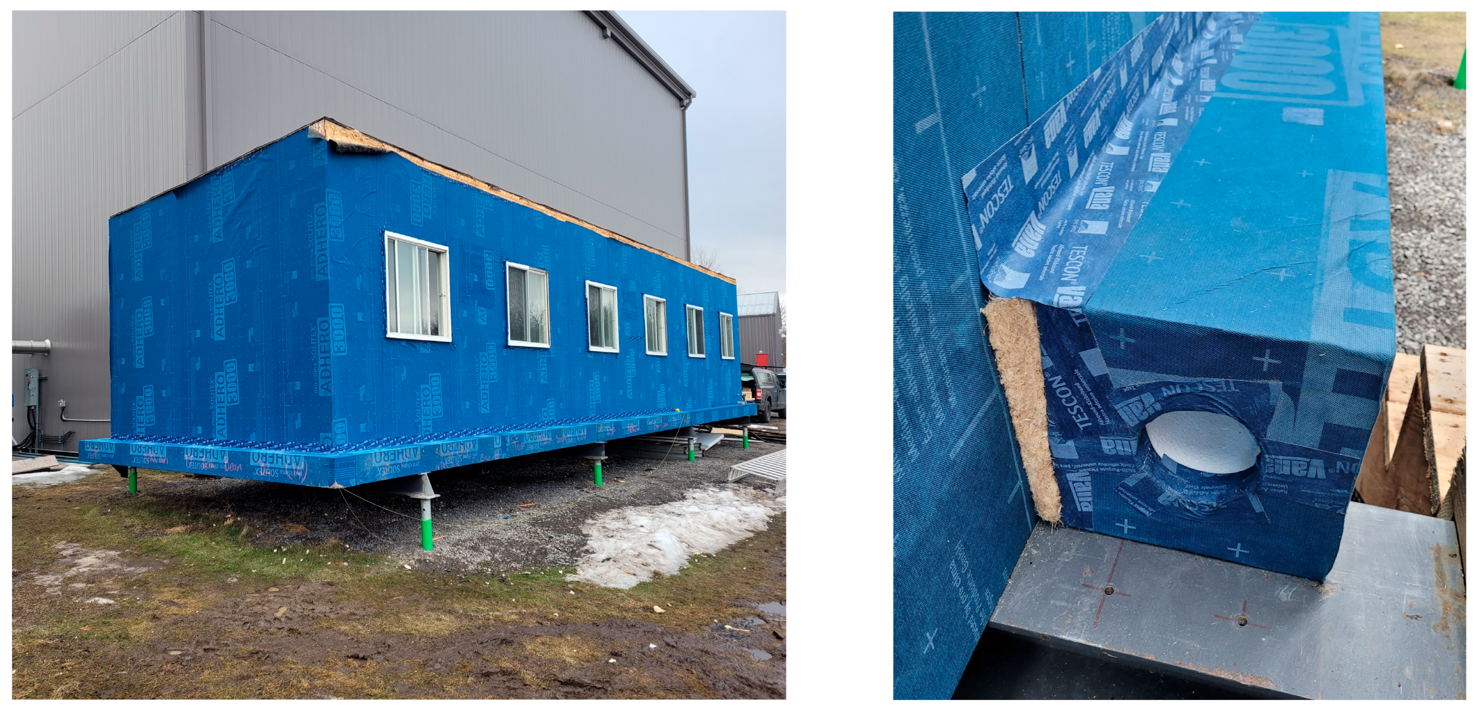
The original structure was an old office trailer (Figure 1). In preparation for the renovation, the trailer was moved into position, and the trailer chassis was removed and replaced with four steel beams supported by helical piles. The insulation under the floor of the trailer was limited and in need of replacement. Joist cavities were insulated with RSI 4.9 (R-28) mineral wool batts, and RSI 1.8 (R-10) high-density EPS foam was placed under the framing to support the batt insulation and further insulate the floor. Plywood sheathing was then installed outboard of the foam insulation and taped to serve as the primary airtight layer of the floor system and to protect the assembly from pests. Finally, the existing leaking cladding was removed, and the building was wrapped in a self-adhered vapour-open water-resistive barrier (WRB) to protect it until the retrofitting occurred.

2. Materials and Methods

2.1. Design Stage

2.1.1. Building Capture and Model Creation

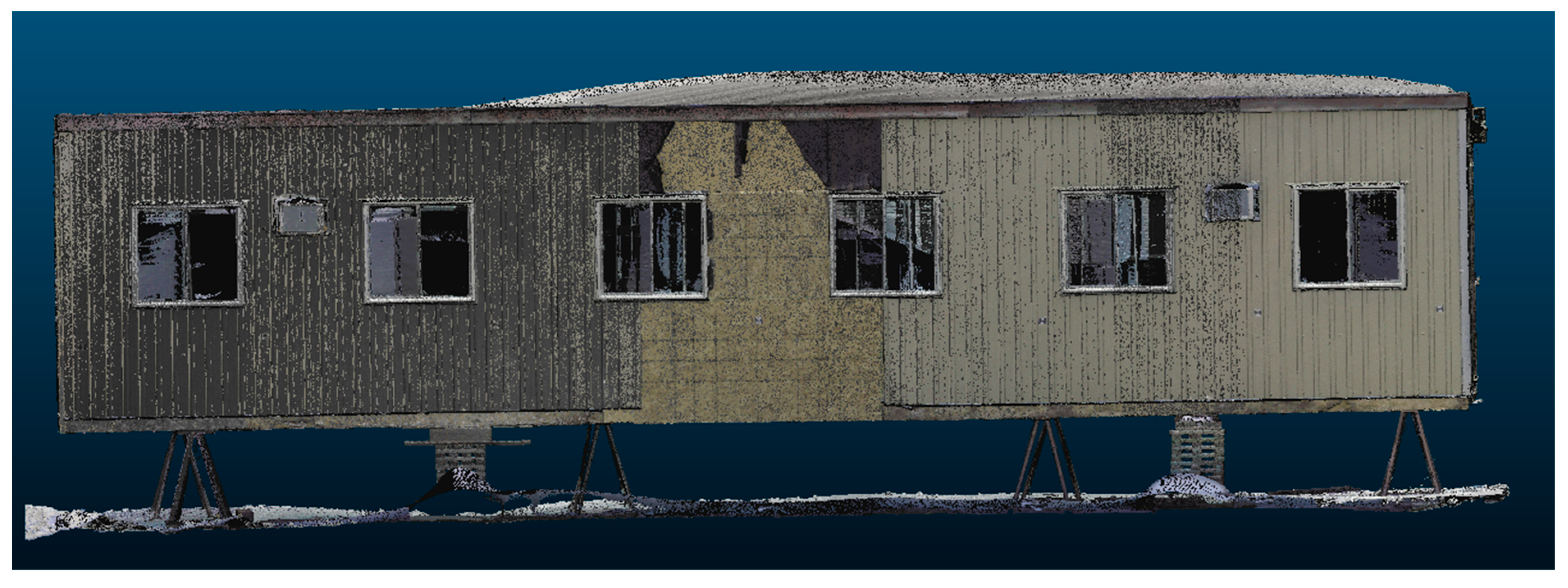
To design panels, accurate building dimensions were required. Even for a simple building, there are several dimensions that need to be captured accurately to ensure that panels fit when they arrive onsite. The building was measured using Light Detection and Ranging (LiDAR), photogrammetry, and hand measurements, and a point cloud of the building was developed (Figure 2). From the point cloud, the locations of points of interest (such as the corners of the building and rough openings) can be determined, and a model of the building can be created, which will in turn allow shop drawings to be designed. One comment that arose from the project partners and from others with experience using point clouds for retrofits was that the person manipulating the point clouds should be the same person creating the shop drawings. This is because some adjustments, assumptions, and fine-tuning are required when manipulating the point clouds and creating the shop drawings, so having the same person or firm perform both tasks reduces the impact of compounding errors.
Once all the building dimensions were confirmed, 3D models were created in Revit and SketchUp. The building dimensions were shared with the panel fabricators, and the 3D model was used for developing and illustrating construction details.

2.1.2. Panel Designs Developed

The panel design for this project was geared towards Part 9 residential buildings in the National Building Code of Canada. These residential buildings are 3 stories or less in height and under 600 m2 building area [21]. With these types of buildings, the panels are not required to support the building structure itself and only need to be able to support their own weight. In regard to fire performance, Part 9 buildings are allowed to be built out of combustible construction, so no fire testing was conducted. As the original structure had no below-grade foundation (as it was set on beams supported by piles), no below-grade retrofit was included in this project.
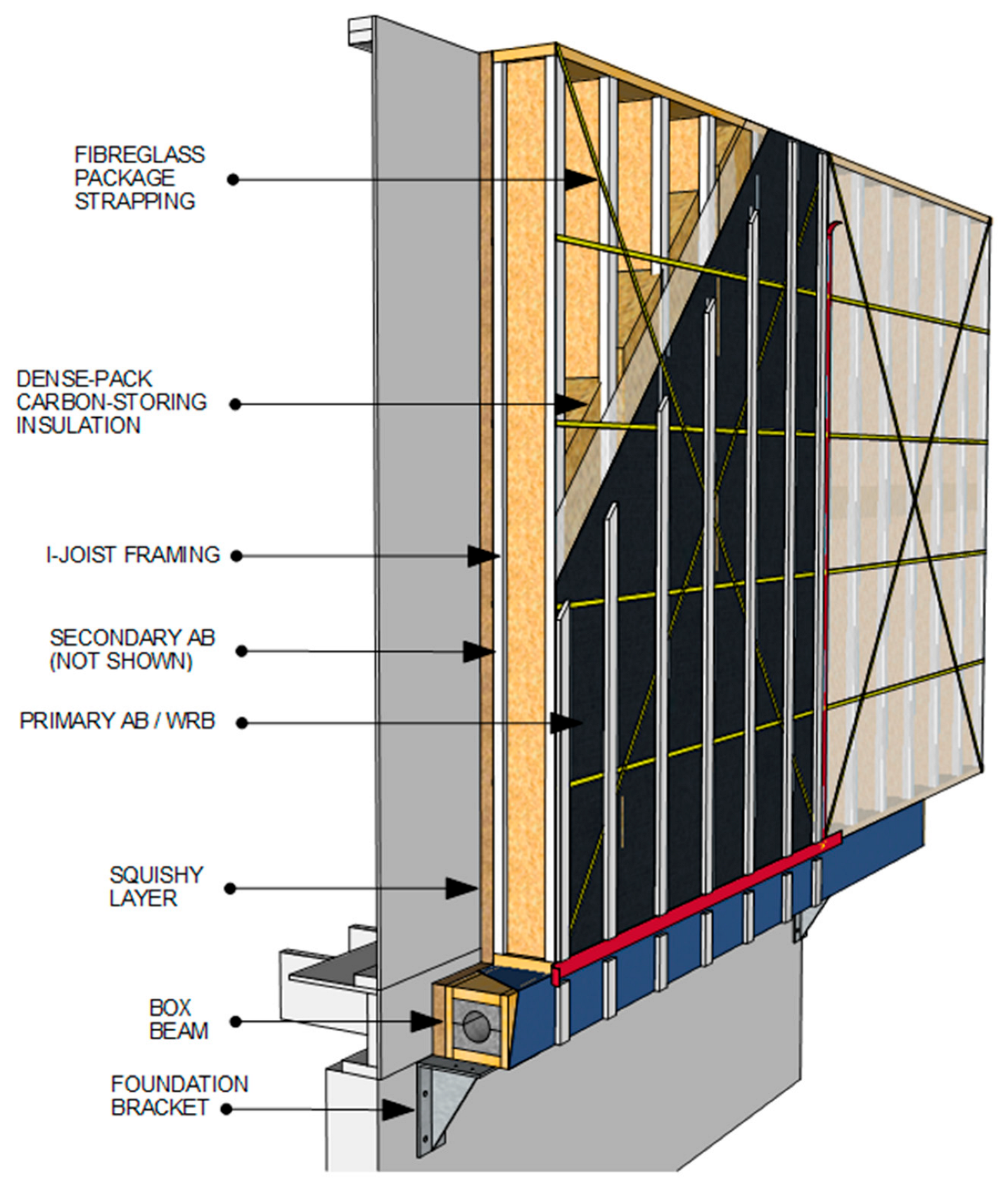
The retrofit design called for R40 (RSI 7.0) walls and R60 (RSI 10.5) roof post-retrofit. As the biogenic insulating materials used had lower thermal performance than traditional materials such as foam insulation, a deeper panel was required. To achieve this, panel designs were developed using I-joists as framing members to provide a deep “outlooker” cavity (Figure 3). I-joists are available in long straight lengths and offer a deep cavity with minimal thermal bridging, which makes them well suited for thick insulation panels. The framing cavities were dense-packed with chopped straw or cellulose. Wood fibre board insulation was used to insulate the web cavity at panel edges and in small cavities where dense packing would be difficult. The wall panels used 9 ½″ (241 mm) I-joists, and the roof panels used 14″ (356 mm) I-joists.
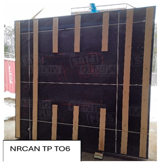
As the wall panels were not structural, and drying potential was a concern with biogenic materials, it was decided that the wall panels would be constructed without sheathing, and packing straps (which could be removed, if necessary, after the install) would be used to keep the panels from racking during transportation and installation. Without sheathing, the panels were less stiff, but they had increased drying potential. The panels included a primary Air Barrier and Water Resistive Barrier (AB/WRB) on the outside face, and a secondary AB/WRB on the inside face of the panel. These barriers helped to make the new structure more airtight and watertight and protected the moisture-sensitive biogenic cavity insulation during transit.
Steel brackets were used to support the panels (Figure 3). Normally, such brackets would be connected to the foundation, but, in the case of the LCCR, which sits on steel beams, the brackets were connected to the existing floor system rim. Insulated box beams span between brackets and support the panels (Figure 3). The box beams allow the brackets to be placed at regular intervals, which in turn allows the panel widths to be more flexible. The box beams could also be installed without the use of a crane, which can help to minimize the amount of time a crane is required onsite. The box beams can also include an MEP (mechanical, electrical, and plumbing) chase. The box beams were designed to be constructed with laminated strand lumber (LSL) rimboard web and dimensional lumber flanges, insulated with a two-piece Graphite Polystyrene (GPS) foam core, with an optional machined hole in the centre.
Because few existing buildings are perfectly level, plumb, and square, retrofitting projects present a greater amount of design uncertainty for prefabrication than for new construction. A variety of measures were implemented to increase tolerance and ensure the final retrofitted panels would fit. A 2″ (51 mm) hemp batt insulation was used as a “squishy” interface layer between the existing building and panels. This “squishy layer” would be installed on the structure or on the panels and was planned to be compressed to roughly 1″ (25 mm) to accommodate any irregularities in the building and to ensure the panels remain plumb.
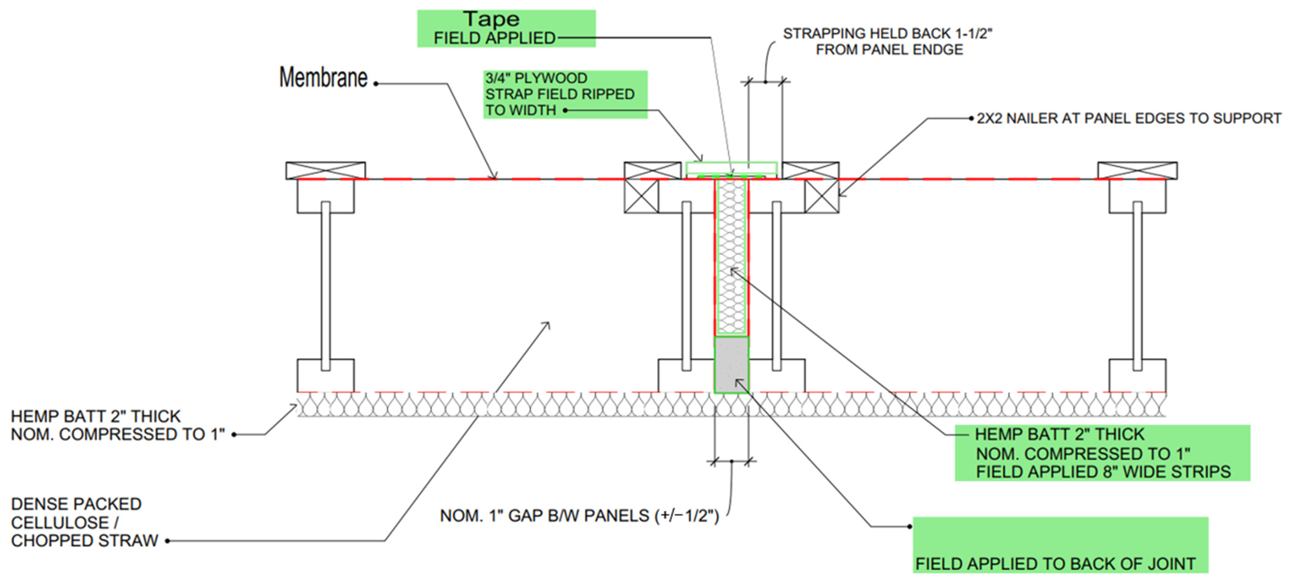
As there is also some uncertainty laterally, a nominal 1″ (25 mm) gap was designed between panels. This gap could expand or shrink by ½″ (13 mm) to increase the lateral tolerance when aligning the panels. This gap was filled with a 2″ (51 mm) hemp batt insulation, which could be compressed to size, as well as a gasket material to help air seal the vertical panel joint (Figure 4). To increase tolerance and to make it easier to align the panels to existing rough openings, the panel’s window rough openings were shrunk by ½″ (13 mm) on all 4 sides. The door rough opening was not shrunk, so this panel needed extra care when being installed. The other panels could be aligned around the door panel to ensure a good fit.
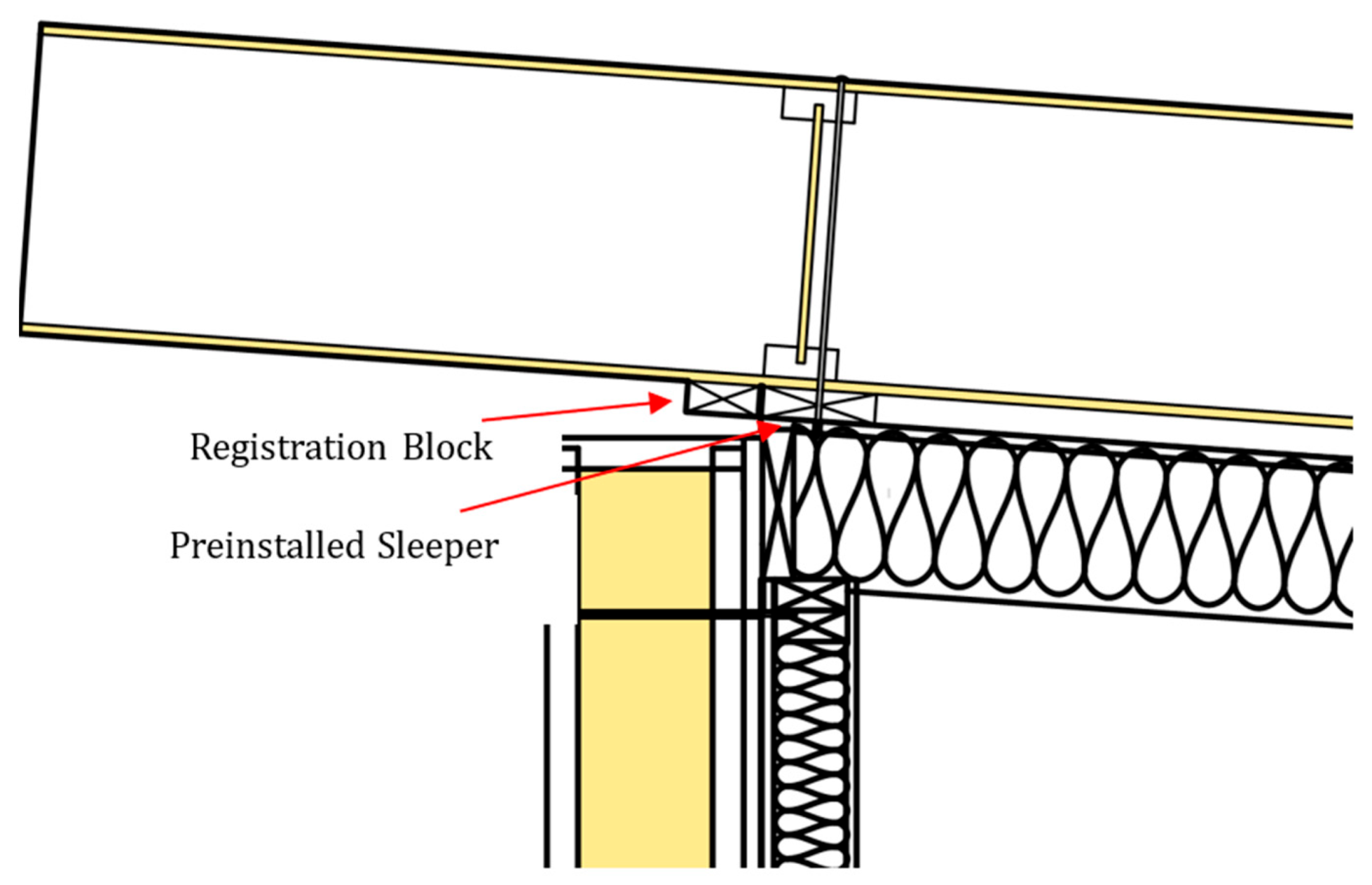
As the existing structure had a low-slope roof, roof panels were designed to span the whole width of the building, and additional overhangs were added. A 2 × 4 registration block was fastened to the underside of the roof panels to catch a 2 × 8 sleeper pre-installed on the existing roof (Figure 5). This facilitated panel alignment during installation. As the roof panels are unventilated and insulated with biogenic insulation, they are reliant on a very airtight installation to ensure warm moisture-laden air is not introduced into the assembly, where it could condense with no real drying mechanism. As the retrofitted roof panels were installed over the existing continuous modified bitumen roofing membrane, it is unlikely that interior air would reach the panels.

2.2. Fabricator Work

2.2.1. Shop Drawings Were Developed

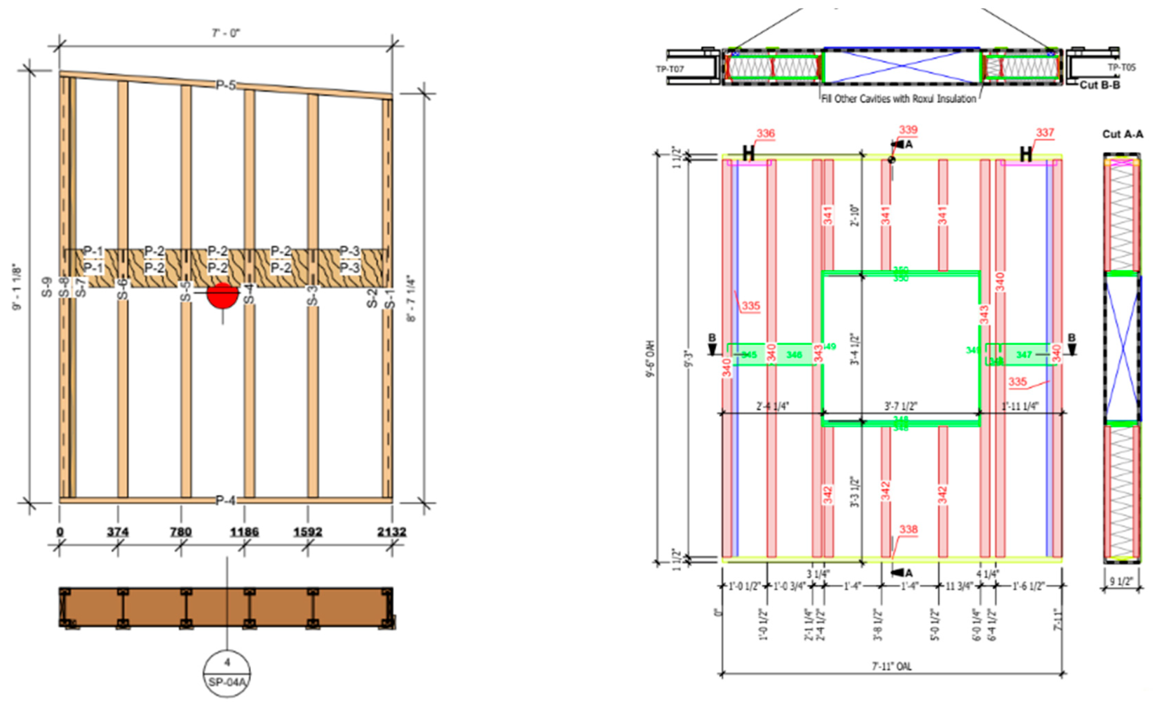
Both panel fabricators developed their own shop drawings for their respective panels, using their typical software and processes (Figure 6). To develop the shop drawings, fabricators first needed to determine panel sizes and layout, location of structural members and blocking, the location of rough openings within panels, etc. The final shop drawings included pick points for handling the panels, the centre of mass, as well as the location of framing and blocking.

2.2.2. Panel Fabrication

The panels were prefabricated offsite by two different manufacturers. The cellulose panels were connected using structural screws, with extra reinforcement around the pick points. The straw panels used nails, and there was no reinforcement around the pick points. Once framed, one side of the panel was covered in membrane. For the cellulose panels, an insulation retention mesh was placed on the other side of the panels, and cellulose was blown in, and then the WRB was added to finish wrapping the whole panel. For the chopped straw panels, no mesh was used, and initially the panel was fully closed with airtight WRB membrane before insulating. This prevented the escape of air while insulating, causing blow-out. The second attempt involved pre-filling the cavities with chopped straw to prevent buildup of air. Once the panels were insulated and sealed, the window opening rough sills were flashed, and the panels were strapped.
While the fabricators were able to prefabricate the panels offsite, the process was still mostly manual. With higher demand for prefabricated retrofits, investments in automated machinery would become more economically viable.

2.2.3. Panels Loaded and Shipped

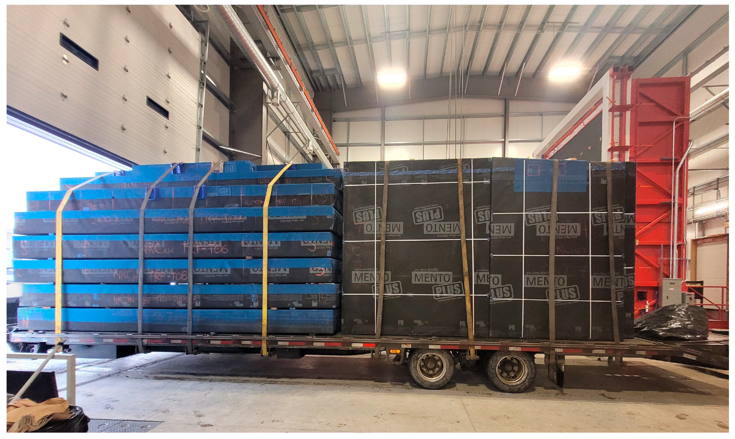
Part of the prefabrication process was to determine how best to lay out panels for transportation, so they fit efficiently (Figure 7). Panel heights (and sometimes widths) are dictated by the trucking restrictions. Keeping a panel height below 8’6 is required for panels that are being shipped horizontally [22,23]. If the panels are being shipped vertically, then the maximum panel height can be higher, depending on the height of the trailer that will be delivering it and local vehicle height restrictions [23]. Panels can be shipped horizontally if there are no windows, but, if windows or doors are pre-installed (factory installed), they need to be shipped vertically to reduce the likelihood of damage. Efficiency in stacking the panels is important to reduce the overall shipping costs. Ideally, the load order is the inverse of the desired install order. Panels can be loaded and unloaded with either a crane or a forklift with fork extensions.

2.3. Onsite Work

2.3.1. Building Preparation

The wall AC units, light fixtures, and attached deck were removed, and the penetrations were sealed. The old windows were left in place, but the trim was removed. In a typical structure, the existing cladding might need to be removed, but it is also possible for the panels to be installed over existing cladding with an appropriate squishy layer capable of accommodating the dimensional differences in the cladding. Installing the panels over existing cladding would also require that the substrates of the assembly are still in good condition (no mold, damage, etc.).

2.3.2. Brackets and Box Beam Installed

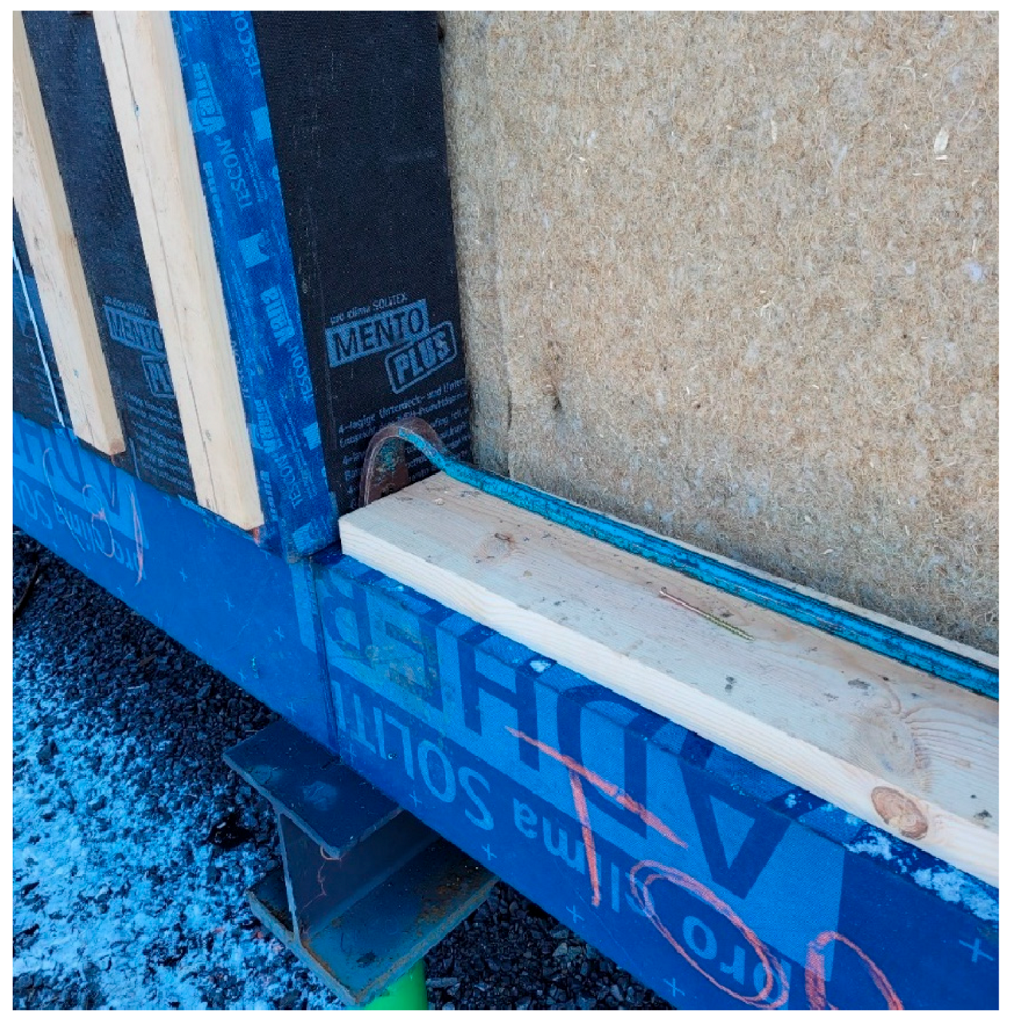
After the building preparation, the brackets and the box beams were installed. The brackets were positioned using a laser level and fastened with structural screws to the existing floor system. Next, the box beams were placed level on the brackets and fastened through the bottom of the bracket screws. The squishy layer was placed between the box beam and existing building and compressed during the alignment process. The box beam was then taped to the WRB to air seal the beam to the backup wall and to flash the hemp squishy layer temporarily (Figure 8).
The box beams were fabricated longer than required so they could be cut to size onsite. In a larger-scale project or if box beam retrofits become more commonplace, box beams could be prefabricated in set sizes and produced in bulk quantities. These box beams could then be shipped before the panels arrive so that the entire building could be prepared without using any crane time.

2.3.3. Wall Panel Installation—Hemp Squishy Layer

The 4′x′8′x2″ thick hemp batt squishy layer was tacked in place on the existing sheathing using 2″ staples. The hemp was cut using a track saw as it is too tough to be cut with an insulation knife. The hemp had to be installed on the day the panels were installed as it could not get wet, and if it was to be left out with potential wind more staples would have been required to tack it in place. The hemp layer was 2″ (51 mm) with a 35 kg/m3 density. The intent was to compress it by 1″ (25 mm) nominally during the panel installation. This ended up being difficult as the hemp was not easy to compress at this density.

2.3.4. Wall Panel Installation—Crane

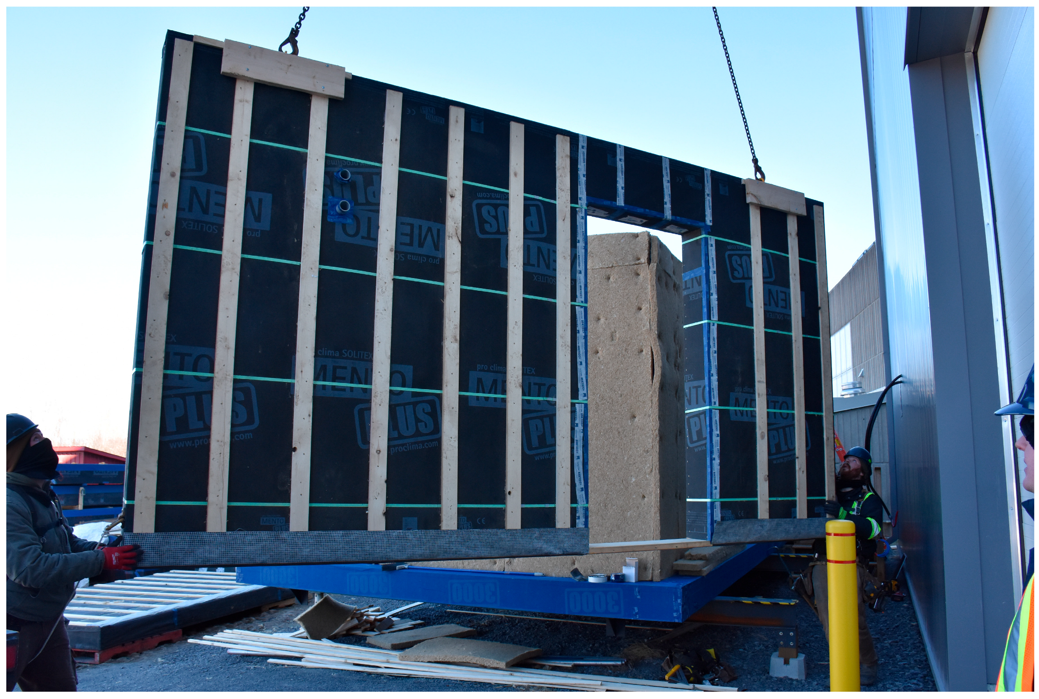
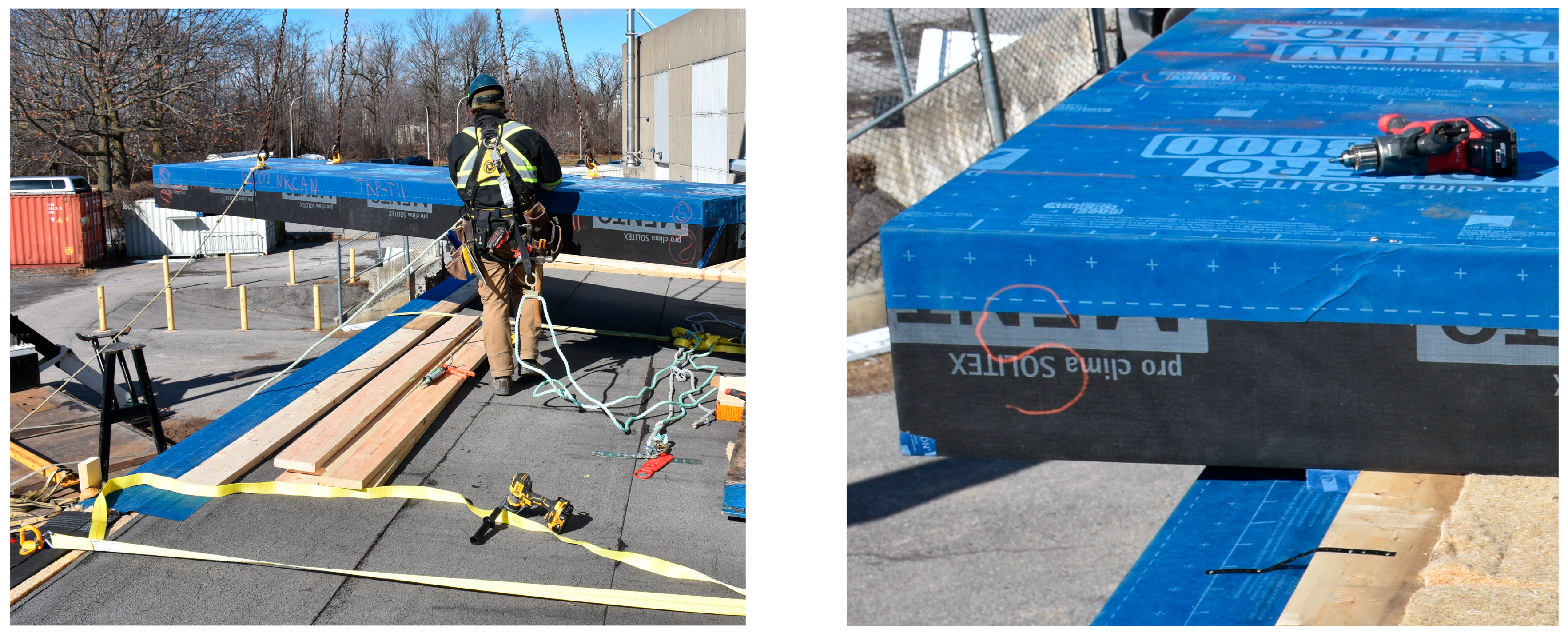
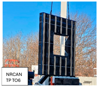
The panels were lifted by crane (Figure 9). The panels themselves had D-rings pre-installed to make hoisting them fast and simple. A bead of durable airtight adhesive was placed on the box beam to connect the secondary airtight plane at the interior panel face [24]. Panel registration was performed by aligning panel rough stud openings (RSOs) with existing RSOs. The vertical panel joints could easily grow or shrink as necessary.
A long prybar was used move the panels fore and aft (Figure 10), and rachet straps attached to the D-rings were used to pull the top of the panel into place. Aligning the panels took more time and required excessive racking force from the prybar since the hemp batt placed between panels was more difficult to compress than expected. The straw panels’ studs were connected to plates with nails, and it appears that the nails were sheared through the force applied to move the panels into position. The cellulose panels had screws connecting the framing, and they were able to withstand the forces used to pry the panels into position. It is expected that using a “panel puller” tool would have resulted in the same issue. A better solution would be specifying a more compressible material for the vertical panel joint or filling the joint after the panels are installed.
Once the panels were aligned properly, they were screwed into place at the top and the bottom. The panels were toe-screwed into the box beam at the bottom and connected into the top plate of the building using long stainless-steel screws with washers to prevent them from pulling through.
Stainless steel screws were specified for their lower thermal conductivity, but these have a relatively high cost (CAD 2.5–CAD 4/screw) and still result in some minor thermal bridging (Chi-values of roughly 0.000224 W/K). Using brackets connected at the panel edges that would later be concealed would be more cost-effective and would reduce thermal bridging. As an added advantage, if all connections could be made at panel joints, panels could be factory-clad more readily.
Most of the panels were of a similar size, being roughly 8 feet wide. These panels took a 3-person crew roughly 15–20 min each to install (rigging, hoisting, positioning, and fastening each panel, and preparing the joint for the next panel). Two of the panels were larger (~16 ft long). It was assumed that the larger panels would take roughly the same amount of time to install, but there were some difficulties with adjusting the larger panels to make them flush. They took 30–35 min, with most of that being panel adjustment time. The squishy layer had a significant impact on panel adjustment time, so it is likely that the time would be reduced with a less dense material/simpler detail.

2.3.5. Panel Joints

The vertical panel joints were detailed after the first panel was installed (Figure 11). A compressible foam gasket was placed at the back of the panel joint to air seal. The rest of the joint was filled with hemp insulation prior to placing the next panel. The second panel would then be pulled or pried into position, compressing the gasket and the hemp to the 1″ +/− ½″ spacing (25 mm +/− 13 mm). The vertical panel joints were then taped and strapped with field-ripped plywood to fit.
The box beam-to-panel joints did not have any squishy layer or gasket, and the panels were simply placed directly on top of the box beam. A bead of caulking was placed at the back of the box beam to help seal the joint. At the front of the box beam-to-panel joint, the joint was taped. One fabricator left a flap of WRB at the bottom of the panel, which allowed proper shingling of the WRB to shed water without relying on the leading edge of a taped WRB connection. Once D-rings were removed, a transition membrane was used to connect the WRB/AB at the top of the panels to the existing modified bitumen roofing (which was treated as the airtight layer for the roof).

2.3.6. Roof Panel Installation

There were 2 × 8 sleepers installed on the long edges of the existing roof. Further, 2″ thick hemp batts were laid on the roof to fill the cavity between the existing roof and the new roof panels. The roof panels had 4 pick points with D-rings so they were able to be lifted evenly. The registration block at the bottom of the panel lined up with the upper sleeper to align the panels together (Figure 12). Similar to the wall panels, ratchet straps were used to pull the panels into position. The roof panels were butted together flush with no hemp or gasket between them. The panels were fastened to the existing structure with long screws into the sleepers. The D-rings were then removed and holes taped, and the joints between panels were taped.

2.3.7. Window Installation

The old windows were removed just before the new windows were installed. The panel rough openings had already been taped and flashed, and the new windows were set at the mid-depth of the panel. The rough openings were shimmed.
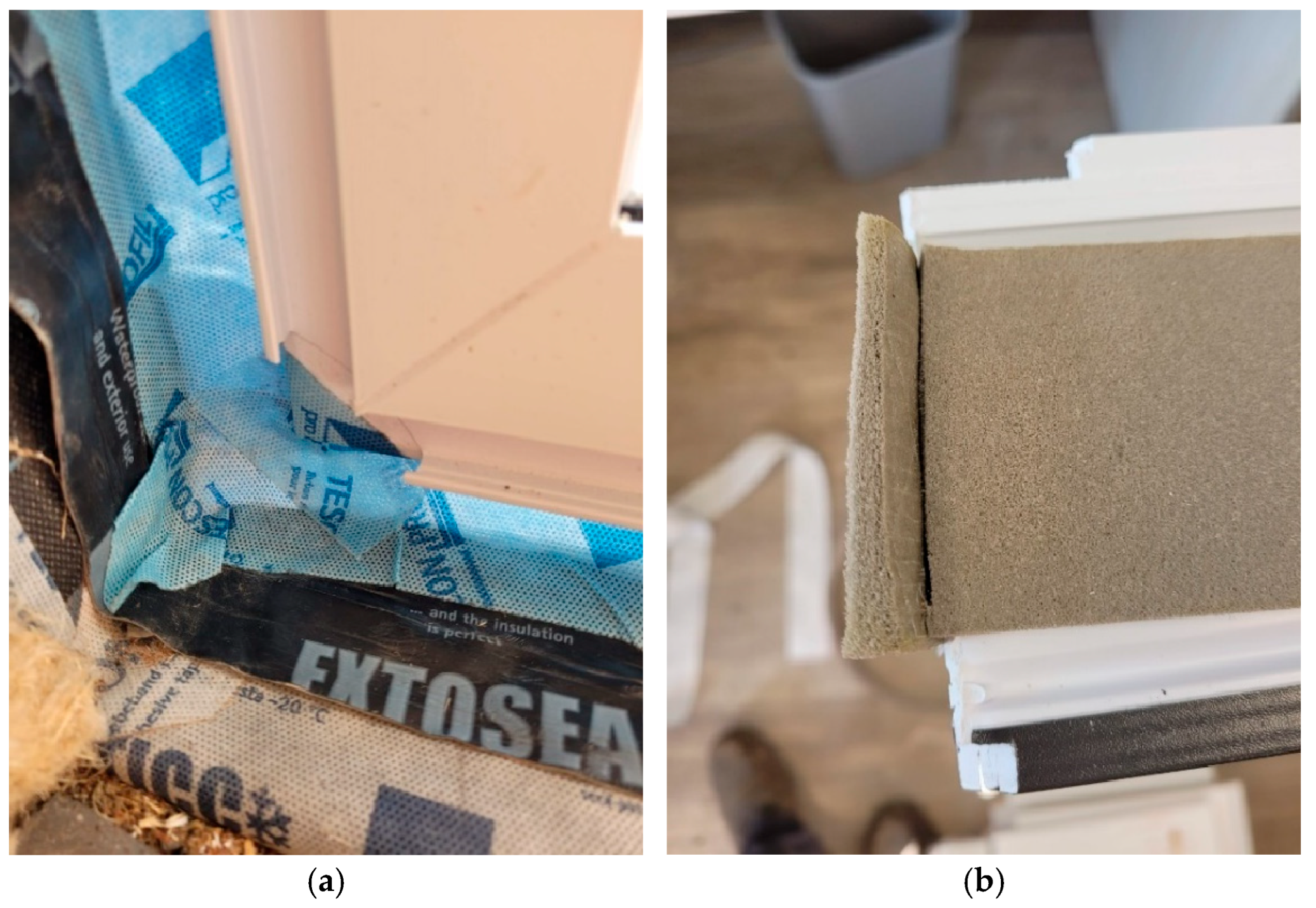
Air-sealing details using a tape and a gasket were trialed (Figure 13). For the taped method, the windows were taped all around the interior edge and along 3 sides of the exterior (bottom left open for drainage). The windows were connected to the RSO (rough stud opening) with screws through the frame, and the tape was connected to the air barrier membrane that was returned into the window openings, The head and jamb rough opening cavities were insulated with canned polyurethane foam.
For the gasket method, the gasket was placed around the perimeter of windows. The window was then connected to the RSO with screws through the frame and screwed into place. The gasket then expanded to fill the gap between the window frame and the RSO.
For all windows, bug screen was installed to terminate the rain screen cavity above and below the window, and aluminum sill flashing was installed. The windows were finished with jamb extensions on the exterior and interior and a picture frame casing on the inside.

2.3.8. Penetrations

The prefabricated panels had penetration holes for electrical and internet cables predrilled, and conduit was placed through and sealed. The larger penetrations for ERV and heat pump line set were left as uninsulated boxes so that conduit could be placed through after panel installation and sealed (Figure 14). Ideally, penetrations are located ahead of time so that they can be precisely located in the shop drawings and fabricated to the exact dimensions. The locations of new penetrations need to be determined within the existing building, and this may not be simple to locate once the panels are installed. One method of locating new penetrations would be to drill pilot holes through the structure from the interior or indicate positions using targets that will appear in LiDAR scans or photo surveys. This will make determining the locations more accurate as measurements for panels are taken from the outside of the structure, but existing framing and equipment placement are usually only located from the interior.

2.3.9. Interior and Exterior Finishing

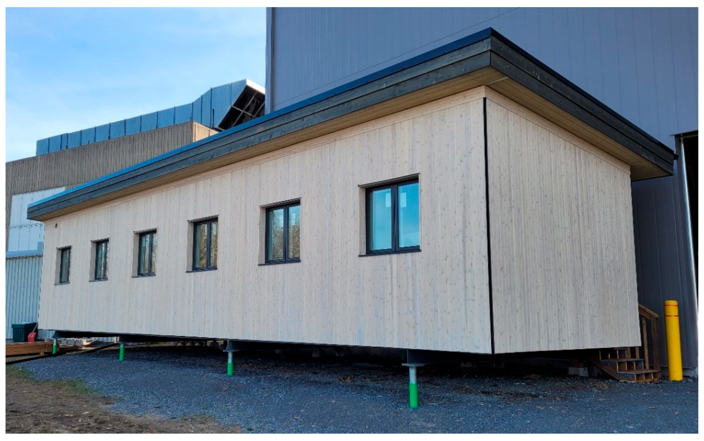
On the building interior, the windows and door were trimmed. On the exterior, the horizontal and vertical cladding, soffit, and facia were installed. One comment that arose was a need for a better nailing surface for the facia boards, which could have been fixed by either installing 2x rims or by using a facia material that was able to span the full depth of the panel in one piece (Figure 15). A new metal roof was installed, with a watertight and vapour-impermeable membrane to project the roof. The majority of the onsite time for the project was for the finishing process as the site preparation and panel installation took about a week and the finishing took roughly 3–4 weeks.

2.3.10. Mechanical Installation

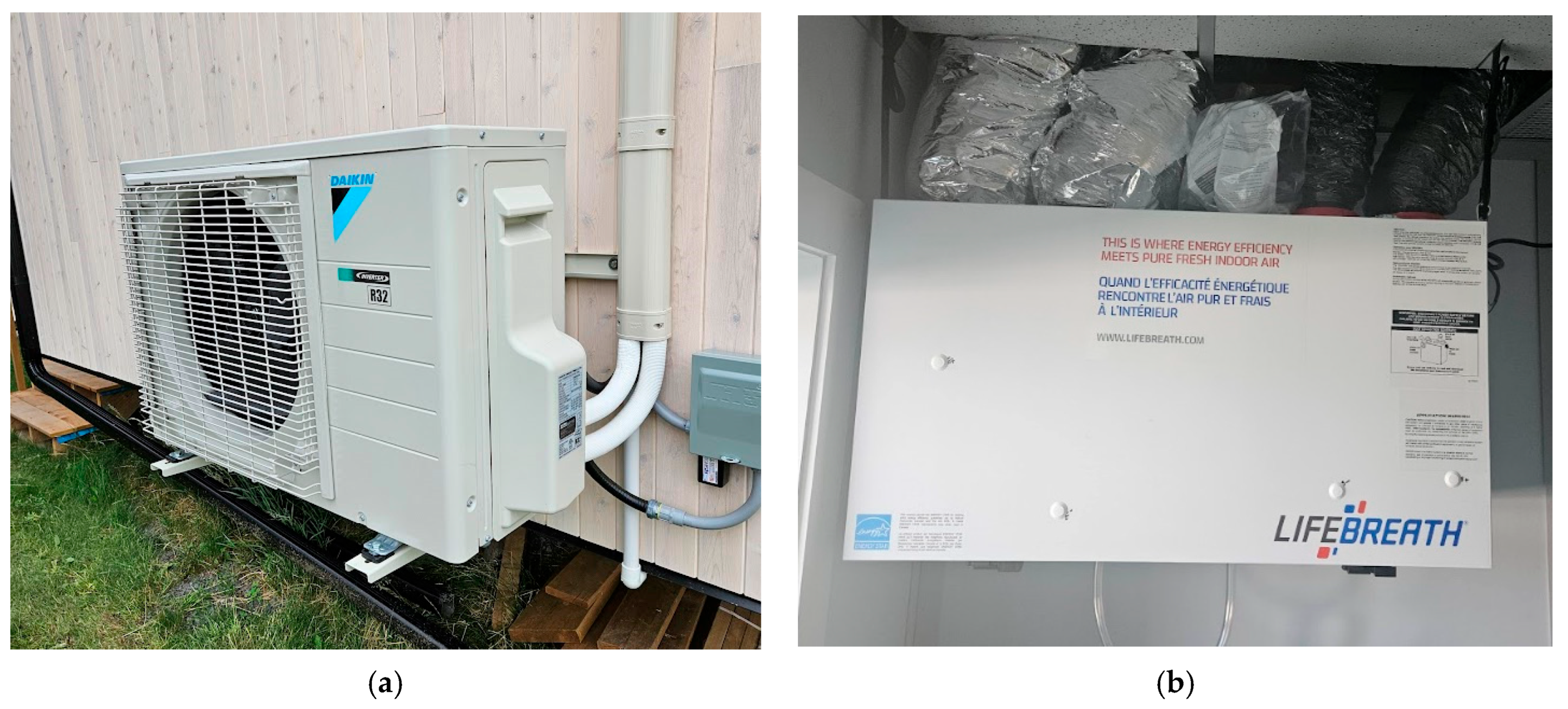
An ERV was installed and ducted to provide ventilation air to all three rooms as the new building would be too airtight to rely on natural ventilation. For heating and cooling, a low-GWP heat pump was installed, and transfer grills were installed in the interior doors to provide better air flow (Figure 16).

2.4. Modelling and Monitoring Methods

2.4.1. Thermal Performance Methodology

A blower door test was performed before retrofitting to establish a baseline, and a second blower door test was performed after the retrofitting process to measure the improvement in air tightness. The thermal performance and air tightness of the pre- and post-retrofit structure were modelled using HOT2000. This model was used to determine the air change rate, normalized leakage area, thermal resistance, design heat loss, and thermal energy demand intensity. The clear field thermal resistance, as well as Ψ-values of the linear thermal bridges and Χ-values of the point thermal bridges were calculated using Flixo Energy 8.2 modelling software. Thermal imaging was also conducted to qualitatively identify any thermal bridges or defects within the post-retrofit assembly.

2.4.2. Embodied Carbon Methodology

For this study, Environmental Product Declarations (EPDs) were used to calculate upfront greenhouse gas emissions associated with manufacturing materials (often simply “embodied carbon”). EPDs often report emissions in a variety of functional units (i.e., kg of CO2e per mass of the materials, volume of the material, assembly area, RSI/m2, R10/100 m2, etc.). In the case of this report, the total kg CO2e emissions were estimated, and the average amount per m2 of wall panel area is provided.
The embodied carbon of the panel designs was estimated using the Material Carbon Emissions Estimator (MCE2) tool. The MCE2 is a free tool developed by Natural Resources Canada and Builders for Climate Action [25]. This tool works similarly to a National Database in that it provides cradle-to-gate information on various building materials. This means the embodied carbon calculations include extraction/harvesting, manufacturing, and all of the transportation involved right up until the material is delivered to site. The source of the data is derived from EPDs, and the data is local to Canada. Users can input the materials they are looking to incorporate in their building to estimate the total embodied carbon. This tool is helpful for comparing the estimated embodied carbon emissions for various options.

2.4.3. Cost Analysis

Exact costing for pilot projects has some difficulties due to the smaller scale and the novel nature of the projects. Estimates for the labour and material costs were collected from the fabricators for the offsite work, and data on the onsite labour and materials were collected. As this is one of several prefabricated pilot projects, the cost/m2 of the past pilots was compared to the current pilot, as well as contractor estimates for conducting similar deep retrofits onsite and estimates for fully new construction.

2.4.4. Monitoring Plan

As the building was retrofitted with two different sets of panels, there were two sets of sensors placed within the new retrofitted panels (one in a cellulose panel and one in a straw panel). These sensors were capable of measuring temperature, wood moisture, and relative humidity. Each panel had three sensors, placed on the panel interior, panel exterior, and centre of the I-joist (Figure 17). There were also sensors placed inside the existing wall, in line with the new panels, and on the interior of the rooms. This allows for a better understanding of heat flow and drying through the assembly. The moisture sensors in particular are needed to ensure that the new panel design does not create any issues with drying to the exterior, and that no part of the assembly is at a point where mold growth is likely to occur.
Sensors for energy monitoring were also installed so that the amount of heating and cooling energy could be compared for each change to the windows (either when window sashes were swapped to a different solar heat gain coefficient or if shading was included in the future). This would allow for a comparison regarding the impact of these windows on the energy use for both the heating and cooling seasons.
One aspect of climate resilience is a building’s ability to remain safe and comfortable during power outages or equipment failure. To determine this building’s resilience, the heating and cooling were shut off during long unoccupied periods during the hottest and coldest periods of the year to determine the indoor floating temperature. The temperature was compared to the safe conditions’ thresholds and exterior temperature to see how long the interior space would remain safe to occupants. For the cooling season, the maximum safe temperature is defined as 26 °C [26]. For the heating season, the safe temperature for comfort is 18 °C, and for long-term safety it is 16 °C [27].

3. Results

3.1. Panel Design

The sheathing-less I-joist panel design was a viable way of producing a thick insulated panel. The panels arrived without significant racking, and the lack of sheathing had no major impact on the installation process. In relation to cost and time, however, both fabricators mentioned that I-joists were more expensive, and they were not as straight and simple to work with as had been anticipated. For this reason, the fabricators suggested modifying the design to a double-stud wall design, which they could fabricate easily and more cost-effectively while still maintaining a thick cavity for blown in insulation.
One question about the panel design that arose involved the necessity of the two air barriers. Having the panels fully wrapped with the membrane made shipping and storing the panels outside uncovered possible as they were fully protected. As moisture ingress into biogenic materials is a major concern, this is a great benefit. The two air barriers also helped to increase the air tightness of the building. Some of the issues of having the panels fully wrapped were the added material cost, labour, and embodied carbon. The membrane has a cost and embodied carbon associated with it, and fully wrapping the panels takes additional time as the panels need to be flipped to allow for proper fastening.
In addition to the membrane itself, this method requires a gasket material at the back of the panel joints to keep the back air barrier continuous. If only one air barrier was needed, this gasket could potentially be avoided, saving material cost, labour, and embodied carbon. However, with the front membrane as the only air barrier, it would have a higher likelihood of damage while installing the panels and cladding and would likely lead to a less airtight building.

3.2. Panel Construction

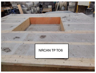
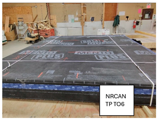
An outline of the fabrication steps for a cellulose panel can be found in Table 1. It provides a list of the steps in the process, the estimated amount of time to complete each step, and a picture. These estimates are rough and based on a 7′11″ (2.4 m) wide and 9′6″ (2.9 m) tall panel, but they provide a good baseline to compare time for offsite construction to onsite construction. The overall time for panel construction was roughly 16 people-hrs, or 2.29 people-hrs/m2.
The panel manufacturers both commented that, while a sheathing-less panel was possible to construct, and the sheathing-less panels were able to be transported without significant racking, the panels took more time and labour to construct, which outweighed any cost savings from not using sheathing. The lack of sheathing required more care to be taken to keep the panels square, and it also limited where the membrane could be attached to the panels. There were also issues with controlling the bulging of insulation once dense-packed, which would have been simpler to accomplish with sheathing (such as in a structurally insulated panel). For the straw panels in particular, there were problems with insulating as the manufacturer did not typically use an insulation retention mesh, and, without the rigidity of sheathing, the staples holding the membrane blew out.
Possible alternative designs to retain insulation while still promoting outward drying include let-in bracing, perforated sheathing (i.e., pegboard), or wood fibre board sheathing (which has a higher vapour permeance than OSB or plywood).

3.3. Installation

3.3.1. Box Beam

The box beams were a success, and they simplified panel installation. The contractors installing the panels found it much easier to install and prepare the box beams first, and then the panel installation/alignment process was more streamlined. As the crane time is costly, work that can be completed to make the installation with the crane faster helps to reduce the cost. As the box beam design relies on the thickness of the panel and is cut to size onsite, fabricators can begin making box beams while the panel designs are being finalized. This can reduce some of the lead time with projects.

3.3.2. Squishy Layer

The squishy layer installed between the panels and the original structure and within the panel joints worked, but there were some lessons learned to improve the process in future projects.
The hemp batt material was stiffer than expected and took more work to compress. This slowed down the installation process in some cases when panels needed to be adjusted. A lower-density material (25 kg/m3 or less) or a thicker hemp layer compressed less would improve panel installation; however, a lower-density material may not hold its shape and may tear when fastened.
The squishy layer was installed on the original structure before the panels were installed, which took some time. The squishy layer could have been pre-installed on the panels; however, as there was no sheathing, it would have been more difficult to attach it to the panels. If this pre-installation were completed by the fabricators, there is also a chance that the squishy layer may become damaged during shipping. For these reasons, installing this layer on the original structure was the optimal choice. However, for taller buildings or buildings with cladding still intact, pre-installing this layer on the panels would likely be the better choice.
The hemp batts that were used are not meant to experience high volumes of water. As such, the installation of the hemp had to be completed close to when the panels were being installed. A hydrophobic material that can tolerate moisture would be beneficial in case it needed to be left exposed overnight or for an extended period of time. A hydrophobic material would likely also be needed if the squishy layer was to be pre-installed on the panels as there is a higher likelihood of it getting wet during shipping or storage onsite.

3.3.3. Panel Installation and Joints

The gasket material used to air-seal the back of the panel joint was quite expensive, had a high embodied carbon content, and it took additional time to apply it to the joint. The self-adhered gasket material also had issues adhering at lower temperatures and when it was applied to the full vertical length of the panel (the weight of the gasket caused it to peel off the panel in some instances). Alternatives that were considered were to provide an intentionally large gap between panels, which would allow for manual taping at the back of the panel. The larger gap could then be filled with a thicker compressible batt material (such as the hemp).

3.3.4. Roof Panels

The registration blocks made panel alignment much faster, and panel adjustment was also much simpler. Once the first panel was set in place, all the subsequent panels could be placed rather quickly. As the roof panel joints were all butted together (no gasket or insulation needed to be installed between panels), a roof panel was installed in about 10 min, roughly half the time of a wall panel. This could be accomplished because the roof had no penetrations that needed to be worked around, and the final overhand depth was flexible.

3.3.5. Windows

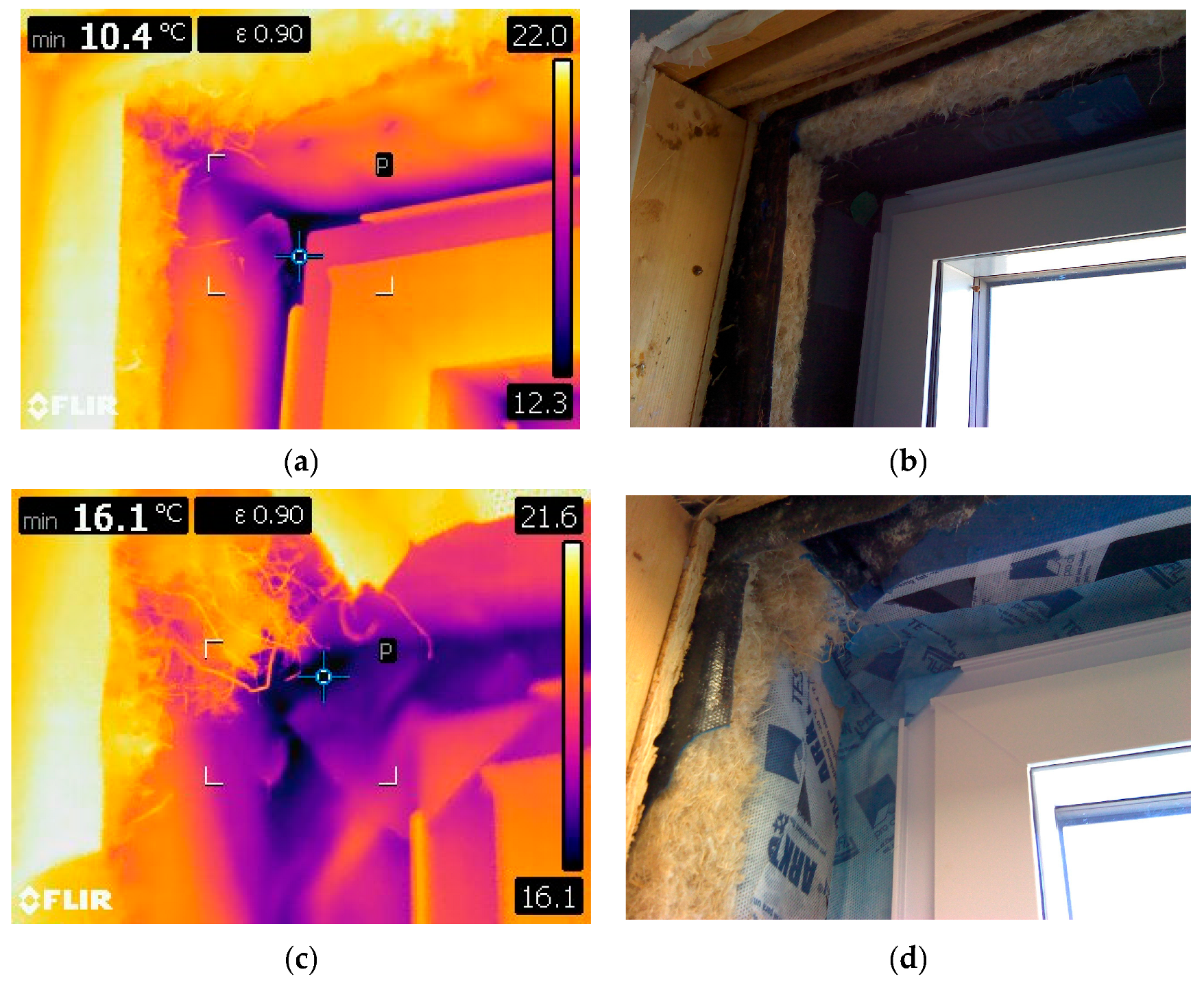
Two different air-sealing methods were trialed, and each had its own pros and cons relating to cost, installation, and thermal performance. The gasket material was about four times as expensive as the tape. The windows chosen had a low-profile design, which made taping difficult and required some trial and error to navigate corners. The tape also provided limited dimensional tolerance during the window installation. For the gasket option, the installation was fast and simple. The gasket provided some tolerance to adjust the position of the window in the RSO (+/− 3/16″ (5 mm)). With the gasket method, it would be possible to pre-install windows in the shop with the gasket and adjust them slightly once they arrive onsite. This would provide the field crew with a bit more flexibility to adjust window position. Through thermal imaging (Figure 18), it was found that the tape and spray foam performed better thermally than the gasket. The reduction in thermal performance could potentially be mitigated by using a wider gasket.

3.4. Thermal Performance

The retrofitting thermal results are summarized in Table 2. One focus of the retrofitting process was to improve the air tightness. Each of the panels was airtight, and every joint was taped and sealed. The number of penetrations was minimized to reduce air leakage. The pre- and post-retrofit building was modelled using HOT2000 V11.12 modelling software. The post-retrofit had a measured air change rate of 0.26 ACH@50Pa and a normalized air leakage area (NLA) of 0.074 cm2/m2. Typical air tightness for buildings ranges around 11–3 ACH@50Pa for buildings built pre-1946 to 2011, respectively [28]. While the national building code of Canada does not mandate air tightness, for new construction in Canada, under 3 ACH@50Pa is considered good, with high-performance homes like Passive House aiming below 0.6 ACH@50Pa [21,29].
Another project goal was to increase the thermal resistance of the walls and roof. New construction in Canada typically aims for above R20 walls and R30 roofs. For this project, the goal was R40 (RSI 7.0) for the walls and R60 (RSI 10.6) for the roof, and this goal was achieved (the chopped straw walls reached R40, and the cellulose wall panels performed slightly above R40). The overall thermal energy demand intensity (TEDI) was decreased by 97%, to approximately 8.0 kWh/m2a, which is within the typical net-zero or PHIUS performance range for most Canadian climate zones.
To determine the thermal performance of individual assembly pieces, thermal models were created using Flixo Energy 8.2. This included calculating the performance of the two different panel types, as well as accounting for the various linear and point thermal bridges (Ψ-values and Χ-values). The linear thermal bridges included the window-to-wall interface, the vertical panel joints, and the box beams. The point thermal bridges included the long screws, as well as the brackets that were used to support the box beams. The results can be found in Table 3. The vertical panel joint was found to be below 0.01 W/m·K; therefore, it can be considered thermal bridge-free. The box beam and windows were found to contribute some thermal bridging, accounting for roughly 2.7% and 5% decreases in overall thermal resistance, respectively. The foundation brackets were found to have a small amount of thermal bridging, and the long screws were found to have a negligible amount of thermal bridging. As they had low Χ-values and limited quantities used, their impact on the overall thermal performance was limited. If more brackets or screws were required to fasten panels into place, their impact could become more significant.
To gather qualitative information on thermal bridging and to obtain a visual representation of heat flow through the building, a thermal imaging camera was used (Figure 19). The interior of the building was set to 21 °C, and the exterior temperature was −4 °C. The thermal imaging clearly showed some thermal bridging along the framing (as is to be expected). The panel joints and the box beam did not demonstrate any thermal bridging. The window-to-wall interface had some thermal bridging, although the difference in emissivity of the glass does account for part of the temperature difference in the images.

3.5. Embodied Carbon

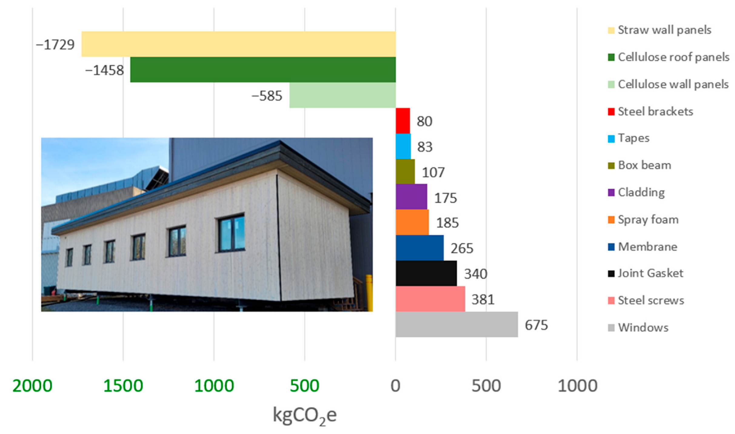
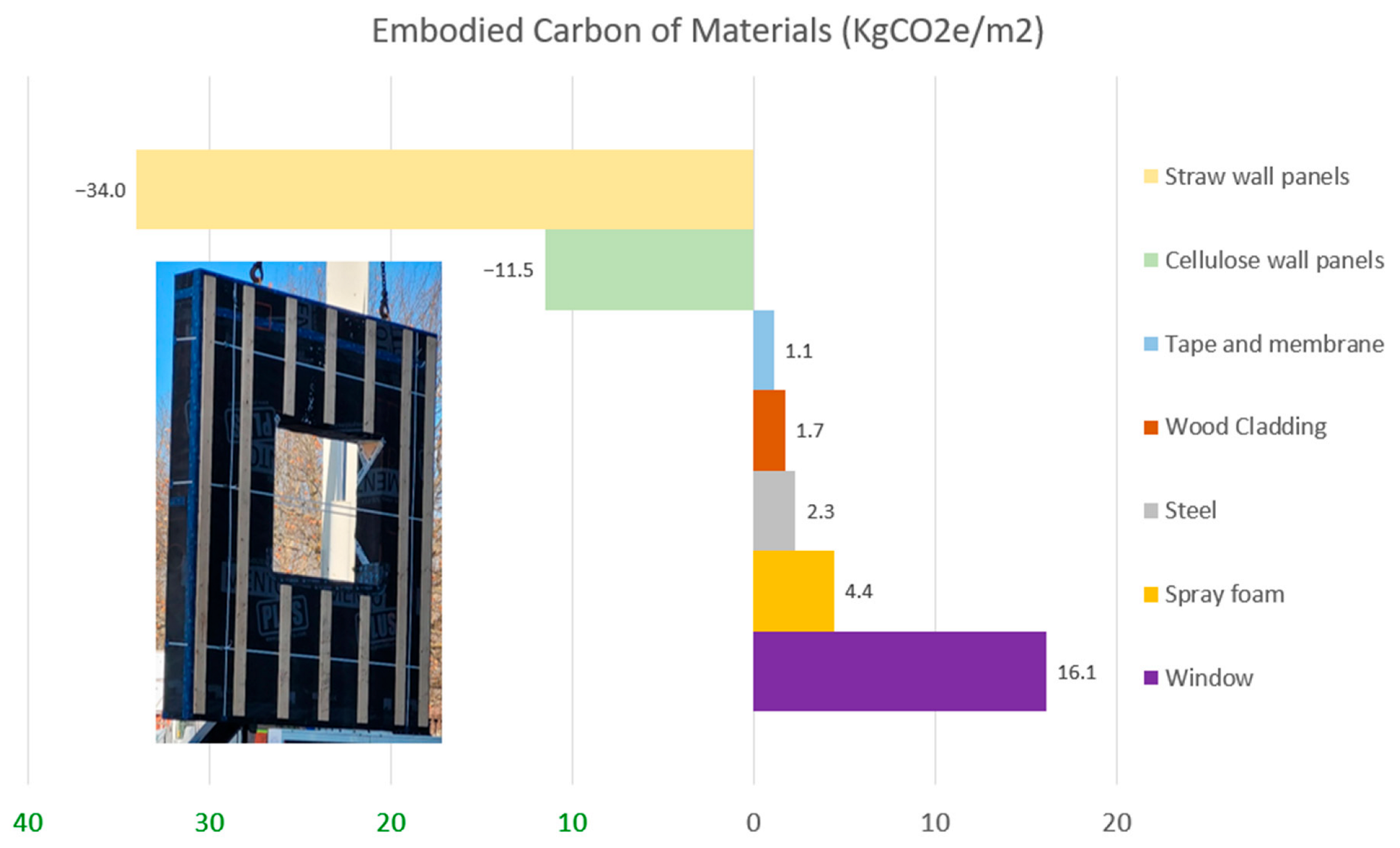
A total of 1480 kgCO2e net carbon storage was achieved during retrofitting from the addition of the new envelope panels and box beams. The contributions of each element can be found in Figure 20. When comparing different panel designs, it can be helpful to take an average value/m2 of panel area to make the comparison simpler. In this case, the cellulose wall panels stored 12 kgCO2e/m2, the cellulose roof panels stored 17 kgCO2e/m2, and the straw wall panels stored 34 kgCO2e/m2 (Figure 21).
It is worth noting that the building components with the highest impact on the embodied carbon are not necessarily those with the largest volume/area. The windows have a large impact on the embodied carbon, especially when combined with the spray foam needed to seal/insulate around the windows. The joint gasket material and membranes are also a large source of embodied carbon, which is another reason to eliminate the secondary air barrier. If only a single air barrier is needed, it would remove all the embodied carbon from the joint gaskets and halve the embodied carbon from the membranes. The steel screws also accounted for a large portion of the embodied carbon. This could be reduced slightly by not using stainless steel screws, or it could potentially be reduced more significantly by designing a method of attaching the panels that could be conducted with shorter screws.

3.6. Costing

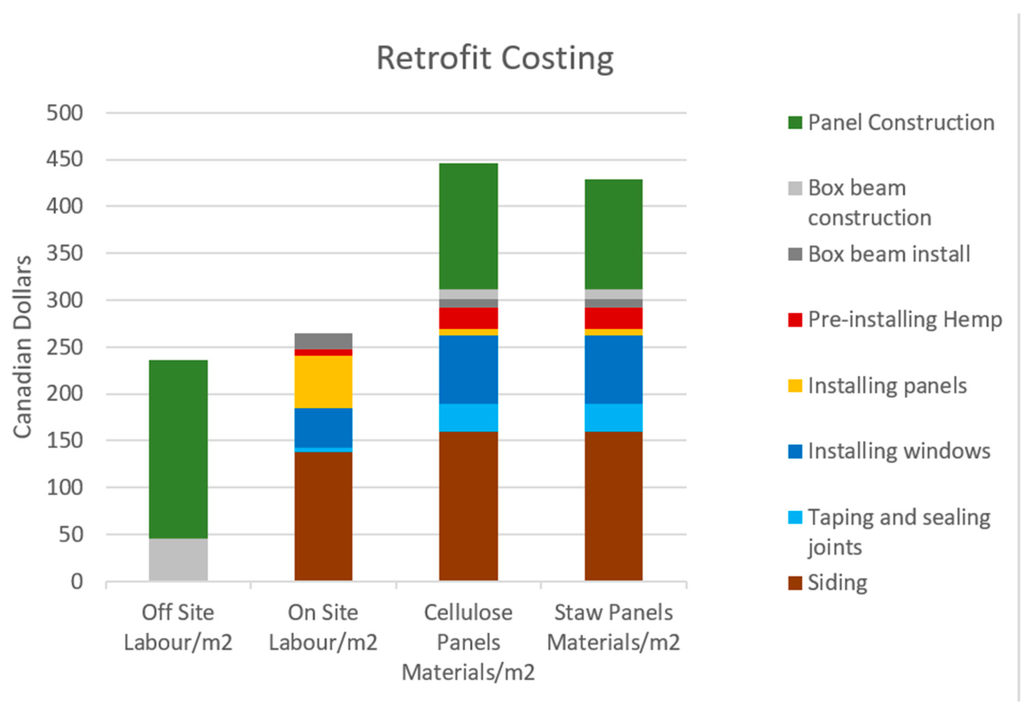
When looking into the costing of such a pilot, it is important to see how the costs break down in terms of the offsite labour cost, the onsite labour cost, and the material cost. The costs of each item can be found in Figure 22. The siding accounted for a large portion of the onsite labour, so, if there is a way to install siding offsite, it could have significant time and labour savings. However, with the current design, installing siding offsite would likely increase the total labour costs as the joints would need special care. In terms of materials, the straw insulation is less expensive than the cellulose, so the straw panels have a lower panel cost.
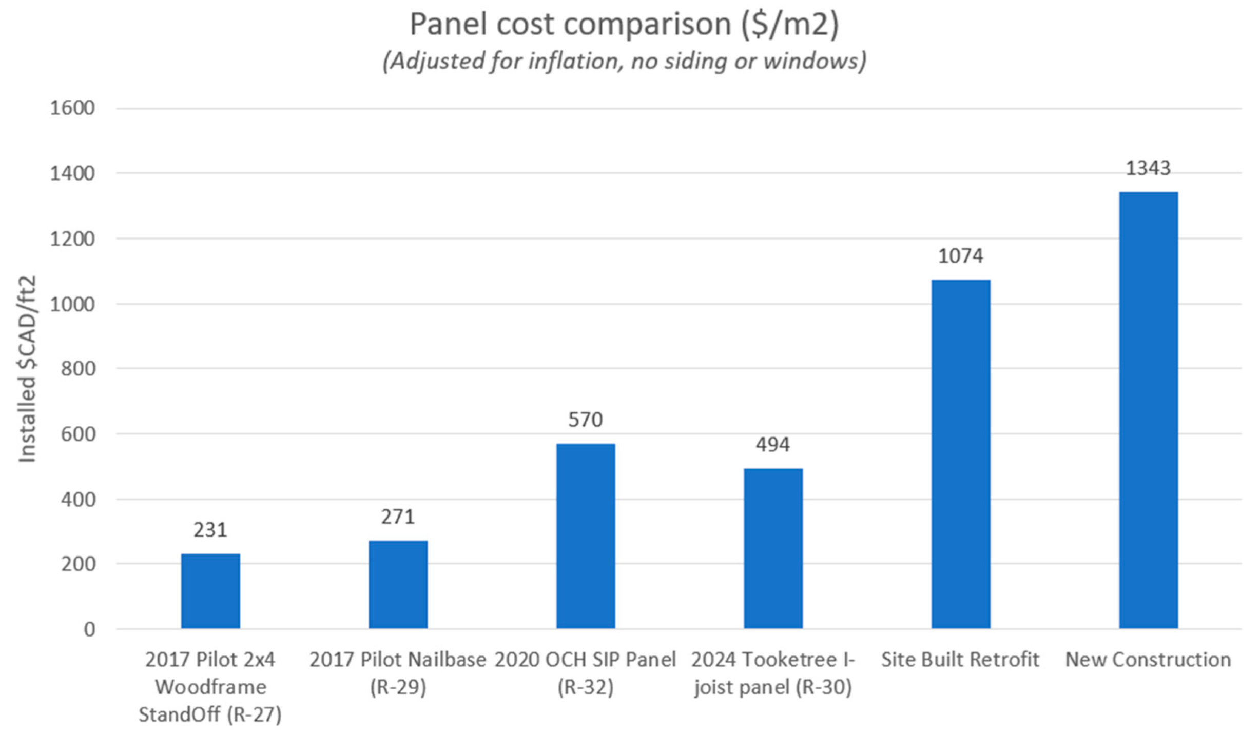
Figure 23 compares past PEER panel designs (adjusted for inflation) with this project’s panel design. These values calculated include all the materials and labour that went into constructing and installing the retrofitted panels (with some omissions noted). The figure also includes estimates for the costs of conducting a similar retrofit with existing onsite methods, or the cost of a new build. It is important to note that these estimates do not account for costs associated with design, which would likely be higher for the prefabricated approaches.
For the past projects, the prices were adjusted for inflation using the building construction price index [30]. For the site-built retrofit, the material costs would be similar to the prefabricated approaches, although increased waste onsite would somewhat increase the cost. The larger cost difference is related to setting up and tearing down equipment, as well as the increased labour cost of onsite work as it is less efficient compared to work completed in a factory and may be impacted by the weather. For new construction, the costs are higher still as there are even more materials that need to be purchased, and structural aspects need to be considered. New construction also requires finishing the interior, which adds a significant cost. As more retrofitting projects are completed, the estimates of overall costs will become more exact.

4. Conclusions

  • The sheathing-less I-joist panel design was found to be viable for lowrise residential buildings. The panels arrived without significant racking, and the lack of sheathing had no major impact on the installation process. As the I-joists were expensive, the fabricators suggested using a double-stud wall design, which they could fabricate easily and more cost-effectively.
  • Both fabricators mentioned that sheathing-less panels took more time to prepare, and that including sheathing should save time and money (even when accounting for the additional materials).
  • The box beams were a success and simplified the panel installation. The contractors installing the panels found it much easier to install and prepare the box beams first, and then the panel installation and alignment process was more streamlined.
  • A lower-density squishy layer is required to make panel installation easier. This could be accomplished by using a lower-density material or using a thicker hemp batt and planning for it to compress less.
  • Flat roof panels with registration blocks can be installed quite quickly. The first panel takes the most time to install correctly, but once installed, the other panels can be quickly placed, adjusted, and installed.
  • The thermal air tightness and thermal performance of the building were significantly improved post-retrofit. Thermal bridging was modelled, and Ψ-values of the linear thermal bridges and Χ-values of the point thermal bridges were calculated.
  • A total of 1480 kgCO2e net carbon storage was achieved during retrofitting from the addition of the new envelope panels and box beams.
  • The cost of labour and materials for the retrofitting process was outlined and compared to other retrofitting projects, onsite construction, and new construction.
  • The prefabricated wall panels have been instrumented, as well as the interior of the building itself. The thermal and hygrothermal performance of the wall panels will be monitored. The interior conditions of the building will be monitored to study occupant comfort and climate resilience. At certain points during the winter and summer, the power will be shut off to determine the building’s ability to maintain safe living conditions during an extended power outage.

Author Contributions

Writing—original draft, H.P.; writing—review and editing, supervision, and project administration, M.C.; conceptualization, J.A. All authors have read and agreed to the published version of the manuscript.

Funding

This research received no external funding.

Data Availability Statement

The original contributions presented in this study are included in the article. Further inquiries can be directed to the corresponding author(s).

Conflicts of Interest

The authors declare no conflicts of interest.

References

  1. Actions for a Zero Carbon Built Environment. Architecture 2030. 2023. Available online: https://architecture2030.org/why-the-building-sector/ (accessed on 7 July 2023).
  2. Wang, Y.; Ma, M.; Zhou, N.; Ma, Z. Paving the way to carbon neutrality: Evaluating the decarbonization of residential building electrification worldwide. Sustain. Cities Soc. 2025, 130, 106549. [Google Scholar] [CrossRef]
  3. Government of Canada. Canada’s 2030 Emissions Reduction Plan; Environment and Climate Change Canada: Gatineau, QC, Canada, 2022.
  4. Natural Resources Canada. National Energy Use Database (NEUD) Comprehensive Energy Use Database. 2019. Available online: https://oee.nrcan.gc.ca/corporate/statistics/neud/dpa/data_e/databases.cfm?attr=0 (accessed on 2 January 2024).
  5. HOME. Government of Canada. 2024. Available online: https://data-donnees.az.ec.gc.ca/data/substances/monitor/canada-s-greenhouse-gas-emissions-projections/Current-Projections-Actuelles/GHG-GES/detailed_GHG_emissions_GES_detaillees.csv (accessed on 7 July 2024).
  6. The Canada Green Buildings Strategy: Transforming Canada’s Buildings Sector for a Net-Zero and Resilient Future. Government of Canada, 8 July 2024. Available online: https://natural-resources.canada.ca/transparency/reporting-and-accountability/plans-and-performance-reports/departmental-strategies/the-canada-green-buildings-strategy-transforming-canadas-buildings-sector-for-net-zer/26065 (accessed on 20 July 2024).
  7. Residential Sector Canada Table 2: Secondary Energy Use and GHG Emissions by End-Use. Natural Resources Canada. 2024. Available online: https://oee.nrcan.gc.ca/corporate/statistics/neud/dpa/showTable.cfm?type=CP&sector=res&juris=ca&year=2021&rn=2&page=0 (accessed on 22 July 2024).
  8. BERTIM Consortium. BERTIM—Innovative wood prefabrication for energy efficient renovations: Project results booklet. European Union Horizon 2020 Research and Innovation Programme. 2019. [Google Scholar]
  9. CanmetENERGY. Prefabricated Exterior Energy Retrofit (PEER) Project Guide; Natural Resources Canada: Ottawa, ON, Canada, 2023.
  10. TAF the Atmospheric Fund. The Case for Deep Retrofits; The Atmospheric Fund: Toronto, ON, Canada, 2020. [Google Scholar]
  11. Government of Canada Promotes in-Demand Skilled Trades as a First-Choice Career Path. Government of Canada, 3 January 2022. Available online: https://www.canada.ca/en/employment-social-development/news/2022/01/skills-trade.html (accessed on 2 August 2023).
  12. Affordable and Adaptable Public Buildings Through Energy Efficient Retrofitting. CORDIS EU Research Results. 2018. Available online: https://cordis.europa.eu/project/id/609060/reporting (accessed on 1 January 2023).
  13. New Easy to Install and Manufacture PRE-Fabricated Modules Supported by a BIM based Integrated Design ProceSS. CORDIS EU Research Results. 2020. Available online: https://cordis.europa.eu/article/id/413460-old-meets-new-sustainable-retrofit-of-buildings-through-prefabricated-panels (accessed on 1 January 2023).
  14. BuildForce Canada. Construction and Maintenance Looking Forward; BuildForce Canada: Ottawa, ON, Canada, 2022. [Google Scholar]
  15. Industrialised Energy Efficient Retrofitting of Resident Buildings in Cold Climates. CORDIS EU Research Results. 2022. Available online: https://cordis.europa.eu/project/id/260058 (accessed on 1 January 2023).
  16. Make Net Zero Energy Refurbishments for Houses a Mass Market Reality. CORDIS EU Research Results. 2021. Available online: https://cordis.europa.eu/project/id/696186/reporting (accessed on 1 January 2023).
  17. Multifunctional Energy Efficient Façade System for Building Retrofitting. CORDIS EU Research Results. 2017. Available online: https://cordis.europa.eu/project/id/285411/reporting (accessed on 1 January 2023).
  18. Energiesprong. What Is Energiesprong. Energiesprong. 2025. Available online: https://www.energiesprong.org/what-is-energiesprong (accessed on 18 September 2025).
  19. Building Energy Renovation Through Timber Prefabricated Modules. CORDIS EU Research Results. 2022. Available online: https://cordis.europa.eu/project/id/636984 (accessed on 1 January 2023).
  20. Holistic Energy-Efficient Retrofitting of Residential Buildings. CORDIS EU Research Results. 2015. Available online: https://cordis.europa.eu/article/id/159896-energyefficient-technology-demonstrated-in-13-old-buildings (accessed on 1 January 2023).
  21. National Research Council Canada. National Building Code of Canada: 2020; National Research Council of Canada: Ottawa, ON, Canada, 2022.
  22. Guide to Oversize/Overweight Vehicles and Loads. Ontario. 2022. Available online: https://www.ontario.ca/page/guide-oversizeoverweight-vehicles-and-loads#:~:text=width%20of%203.70%20m%20on,height%20maximum%20of%204.26%20m (accessed on 6 June 2024).
  23. Mott, H. The good, the bad, and the hygge: Designing for prefab from a manufacturer’s perspective. In Passive House Canada Prefab Symposium; Passive House Canada: Victoria, BC, Canada, 2022. [Google Scholar]
  24. Proclima. System Products. Proclima. Available online: https://proclima.com/products (accessed on 12 December 2024).
  25. Material Carbon Emissions Estimator (MCE2). Government of Canada, 11 July 2022. Available online: https://natural-resources.canada.ca/maps-tools-and-publications/tools/modelling-tools/material-carbon-emissions-estimator/24452 (accessed on 8 July 2023).
  26. BC Building Codes and Standards Branch. BC Codes 2024. 2024. Available online: https://www2.gov.bc.ca/gov/content/industry/construction-industry/building-codes-standards/bc-codes/2024-bc-codes (accessed on 5 September 2025).
  27. Jevons, R.; Carmichael, C.; Crossley, A.; Bone, A. Minimum indoor temperature threshold recommendations for English homes in winter—A systematic review. Public Health 2016, 136, 4–12. [Google Scholar] [CrossRef] [PubMed]
  28. Purdy, J.; Parekh, A. Building Envelope Thermal and Air Leakage Characteristics of Canadian Housing. In CCBST 2017; Vancouver, BC Building Envelope Council: Delta, BC, Canada, 2017. [Google Scholar]
  29. Passive House Requirements. Passive House. 2025. Available online: https://passiv.de/en/02_informations/02_passive-house-requirements/02_passive-house-requirements.htm (accessed on 20 September 2025).
  30. Statistics Canada. Building Construction Price Index. Statistics Canada. 2025. Available online: https://www150.statcan.gc.ca/n1/en/surveys/2317 (accessed on 7 January 2025).
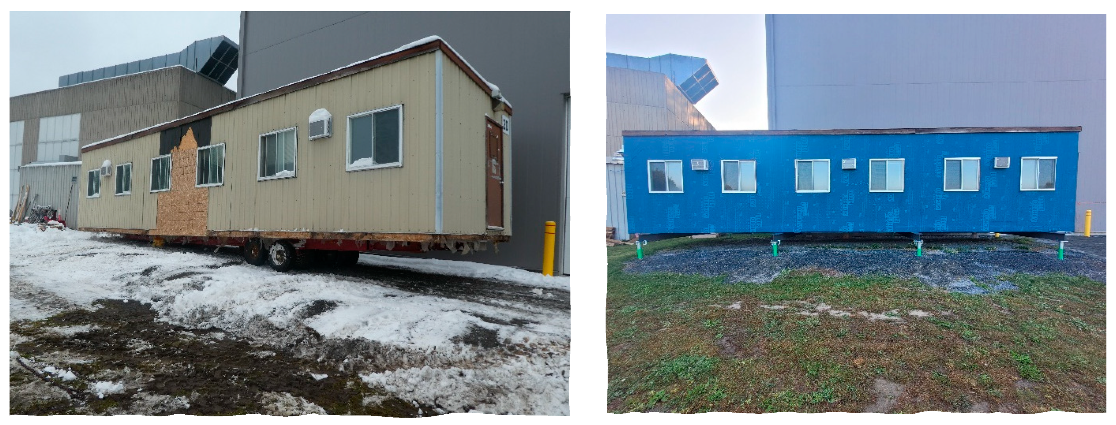
Figure 1. LCCR original structure (left); LCCR before panel installation (right).
Buildings 15 03666 g001
Figure 2. Original building point cloud.
Buildings 15 03666 g002
Figure 3. Retrofit panel design.
Buildings 15 03666 g003
Figure 4. Vertical panel joint detail (plan view). Green items installed on site.
Buildings 15 03666 g004
Figure 5. Roof panel installation detail, registration block, and sleeper.
Buildings 15 03666 g005
Figure 6. Fabricator shop drawings.
Buildings 15 03666 g006
Figure 7. Delivered panels.
Buildings 15 03666 g007
Figure 8. Box beam installation.
Buildings 15 03666 g008
Figure 9. Wall panel installation.
Buildings 15 03666 g009
Figure 10. Prybar panel adjustment.
Buildings 15 03666 g010
Figure 11. Vertical panel joint viewed from above.
Buildings 15 03666 g011
Figure 12. Roof panel installation.
Buildings 15 03666 g012
Figure 13. (a) Taped window detail; (b) gasket window detail.
Buildings 15 03666 g013
Figure 14. Penetration details.
Buildings 15 03666 g014
Figure 15. Finished building.
Buildings 15 03666 g015
Figure 16. Mechanical systems: (a) heat pump and (b) ERV.
Buildings 15 03666 g016
Figure 17. Sensor locations within retrofitted panels (plan view).
Buildings 15 03666 g017
Figure 18. Thermal imaging of the gasket method (a,b) as well as the taped method (c,d).
Buildings 15 03666 g018
Figure 19. Thermal imaging of the building after panel installation.
Buildings 15 03666 g019
Figure 20. Whole-building enclosure retrofit embodied carbon (kgCO2e).
Buildings 15 03666 g020
Figure 21. Embodied carbon of materials per m2 of panel area (for a typical 7 m2 (75 ft2) panel).
Buildings 15 03666 g021
Figure 22. Labour and material costs (CAD/m2 panel area).
Buildings 15 03666 g022
Figure 23. Cost comparison of past deep retrofit approaches compared to estimates for a similar site-built retrofit and new construction.
Buildings 15 03666 g023
Table 1. Construction steps and labour time.
Step Time (People-Hours) Picture
Processing/ripping plates and RSO plywood and cutting members to length0.75 hr × 2ppl
=1.5 ppl-hrs
Buildings 15 03666 i001
Assembling frames and installing blocking5 hrs × 2 ppl
=10 ppl-hrs
Buildings 15 03666 i002
Installing insulating mesh on both panel faces0.75 hrs × 1 ppl
=0.75 ppl-hrs
Buildings 15 03666 i003
Blowing in insulation to required density0.75 hr × 1 ppl
=0.75 ppl-hr
Buildings 15 03666 i004
Installing AB/WRB to fully wrap the panel1.5 hrs × 1 ppl
=1.5 ppl-hrs
Buildings 15 03666 i005
Installing strapping on the panel’s exterior side0.5 hr × 1 ppl
=0.5 ppl-hr
Buildings 15 03666 i006
Installing industrial package strapping/final Q/A1 hr × 1 ppl
=1 ppl-hr
Buildings 15 03666 i007
TOTAL16 people-hours
Table 2. Building modelling thermal results.
Performance MetricBaselineRetrofit% Improvement
Air Change Rate (ACH@50Pa)7.200.2696
Normalized Leakage Area @10Pa (cm2/m2)1.030.0793
Thermal Resistance (R-Value [RSI])Walls13 [2.3]40 [7.0]308
Roof20 [3.5]60 [10.6]300
Design Heat Loss (−25 °C) W3380161052
Thermal Energy Demand Intensity (kWh/m2a)2608.097
Table 3. Thermal performance of enclosure by assembly.
Clear FieldThermal ResistanceSurface Area% Area% Heat Flow
Assembly(m2·K/W)(hr·ft2·°F/BTU)(m2)(ft2)
Floor5.430.950.454222.7%29.8%
Cellulose Insulated Roof12.571.250.454222.7%12.9%
Cellulose Insulated Walls8.246.555.760023.7%22.8%
Straw Insulated Walls8.045.455.760023.7%23.4%
Linear Thermal BridgesΨ-valueTotal Length% Area% Heat flow
(W/m·K)(BTU/hr·ft·°F)(m)(ft)
Window-to-wall interface0.0380.02206.5625212.8%2.7%
Vertical panel Joint0.0040.002339.41261.0%1.0%
Box Beam0.0180.010442.51364.5%4.4%
Point Thermal BridgesΧ-valueQuantity% Area% Heat flow
(W/K)(BTU/hr·°F)
Foundation Bracket0.00630.0116484488-2.7%
Long Screws0.000220.00040677128-0.3%
Disclaimer/Publisher’s Note: The statements, opinions and data contained in all publications are solely those of the individual author(s) and contributor(s) and not of MDPI and/or the editor(s). MDPI and/or the editor(s) disclaim responsibility for any injury to people or property resulting from any ideas, methods, instructions or products referred to in the content.