Article

Effects of Incorporating Iron-Rich Slag on the Performance of Calcium Sulfoaluminate Cement: Strength Development, Hydration Mechanisms and Microstructure

1
School of Civil Engineering and Architecture, Wuyi University, Wuyishan 354300, China
2
Key Laboratory of Smart Town Construction of Hilly Mountains (Wuyi University), Fujian Province University, Wuyi University, Wuyishan 354300, China
3
School of Civil and Transportation Engineering, Guangdong University of Technology, Guangzhou 510006, China
*
Author to whom correspondence should be addressed.
Buildings 2025, 15(20), 3654; https://doi.org/10.3390/buildings15203654 (registering DOI)
Submission received: 18 September 2025 / Revised: 4 October 2025 / Accepted: 6 October 2025 / Published: 11 October 2025
(This article belongs to the Section Building Materials, and Repair & Renovation)

Abstract

Using solid waste from the non-ferrous metal industry as non-traditional supplementary cementitious material has attracted increasing attention. In this study, iron-rich slag (IRS) was incorporated into calcium sulfoaluminate cement (CSC) to improve its properties, and its strength development and hydration mechanism were systematically evaluated. Three types of IRS with distinct particle size characteristics were fabricated through mechanical grinding, and their effects on the strength development and hydration heat evolution of CSC-based materials were investigated. Furthermore, several solid-phase analysis methods were employed to characterize the hydration mechanisms and microstructural characteristics of IRS-containing CSC-based materials. The results show that mechanical grinding enhances the reactivity of IRS in CSC-based systems, which in turn facilitates the generation of hydrates like ettringite (AFt), AH3, and C–S–H gel, thereby improving their strength. The incorporation of IRS effectively decreases the total hydration heat released by CSC-based materials within 24 h. Furthermore, evidence from EDS analysis suggests the possible isomorphic substitution of Al3+ by Fe3+ in AFt, which, along with the slower reaction kinetics of Fe-AFt, may contribute to the improved late-age strength development of CSC-based materials. This study proposes a sustainable strategy for producing high-performance CSC-based materials and offers a potential approach for the high-value use of non-ferrous metal industry solid waste in construction materials, thereby demonstrating both scientific value and practical engineering significance.

1. Introduction

Calcium sulfoaluminate cement (CSC) is recognized as a high-performance building material suitable for marine engineering construction due to its exceptional properties, including fast setting, high early-age strength, corrosion resistance, and low permeability [1,2,3]. Although its production process offers environmental advantages including low carbon emissions, low energy consumption, and reduced CO2 footprint—contributing to a lower environmental burden—the need for large quantities of relatively expensive bauxite resources restricts its large-scale application [4,5]. The key characteristics of CSC (such as fast setting and accelerated strength development) are mainly attributed to the rapid reaction between calcium sulfoaluminate minerals and gypsum, which forms ettringite (AFt) as the primary hydrate [6,7,8]. While CSC demonstrates significant advantages in applications such as rapid repair and construction under low-temperature conditions, it is also limited by relatively weak long-term strength development.
The high-volume incorporation of supplementary cementitious materials (SCMs) offers an important strategy to reduce the preparation cost associated with CSC application, significantly contributing to the maximization of environmental benefits [9,10]. Conventional SCMs, such as natural pozzolans, ground granulated blast furnace slag, and fly ash, have been extensively adopted owing to their high reactivity and low carbon footprint [9,11,12]. However, their localized availability poses challenges in meeting the demands of large-scale engineering applications. With the advancement of industrial technologies, a series of new industrial by-products have emerged, sparking research interest in their potential use as non-traditional SCMs in cementitious blends [13,14].
Solid waste residues (such as copper, lead, and zinc slags) discharged from the non-ferrous metal smelting industry have rarely been reported in the existing literature as SCMs, representing a promising non-traditional SCM [15,16]. Owing to the difficulties in their utilization, the global annual accumulation of such solid wastes exceeds 200 million tons [17]. Although the current production volume of these metallurgical slags is relatively small compared to conventional SCMs, they represent a valuable potential resource in specific localized regions. A distinctive feature of these slags, compared to traditional SCMs, is their higher iron content—specifically higher Fe/Ca, Fe/Si, and Fe/Al ratios—hence being referred to as iron-rich slag (IRS) [18]. This compositional characteristic may influence their hydration behavior in cementitious systems. Relevant studies indicate that IRS typically exhibits low pozzolanic reactivity, which may impair the mechanical properties of cement-based materials [15,19]. Nevertheless, mechanical grinding stands as one of the most common and straightforward approaches to enhancing pozzolanic reactivity and is expected to improve the low reactivity of IRS [20,21]. Given the current trend toward high-volume usage of SCMs in cement clinker, enhancing the pozzolanic potential of metallurgical slags is highly necessary.
Previous studies have indicated that Fe3+ and Al3+ have comparable ionic sizes and identical +3 charges, which makes it plausible for Fe3+ to substitute for Al3+ within the AFt crystal structure without rearranging the lattice. This substitution leads to the generation of Fe-bearing AFt [22,23]. Therefore, the IRS may affect the properties of cement-based materials by altering the makeup and amount of AFt in the system. Furthermore, some studies have proved that the slower formation kinetics of Fe-bearing AFt (compared to Al-bearing AFt) allow other hydrates (e.g., C–S–H gel) to create a relatively stable framework within the cement-based materials [24,25]. As the formation and growth of Fe-bearing AFt gradually slow, the pre-existing skeletal framework can better accommodate induced local stresses. Based on these findings, it can be inferred that IRS has the potential to mitigate the formation rate of AFt, playing a positive role in reducing sulfate-induced expansion in CSC-based materials.
While previous studies have explored the use of IRS in ordinary Portland cement (OPC) systems, research on its application in CSC-based materials remains relatively limited [17]. Furthermore, the distinct hydration mechanisms and hydration product types of CSC (compared to OPC) create a compelling need for targeted performance optimization. Bertola et al. [26] investigated the effect of slag on the properties of CSC and suggested that slag could enhance early-age strength without compromising long-term performance. However, CSC inherently exhibits high early-age strength, and a more critical challenge lies in the effective regulation of its later-age mechanical and durability properties. To address this challenge, this study aims to investigate the incorporation of iron-rich solid waste (IRS) into CSC, with the goal of effectively mitigating its high initial heat release and achieving steady improvement of later-age performance, which necessitates a comprehensive evaluation of its properties. In summary, the combined effects of incorporating IRS in CSC-based systems are relatively complex, and the following research questions need to be clarified: (1) How does mechanical grinding facilitate the high-volume incorporation of IRS in CSC-based systems? (2) What is the mechanism by which high-volume IRS influences the strength development of CSC-based systems? (3) Through which mechanism does IRS affect the reaction kinetics of CSC-based systems?
To address the aforementioned research questions, three types of IRS with distinct particle size characteristics were fabricated through mechanical grinding. First, the influences of various grinding times on the particle size chemical bond reactivity, and morphology of IRS were investigated. Subsequently, by adjusting the dosages of these IRS (with varying particle sizes) in CSC-based materials, the changes in strength development and hydration heat evolution of IRS-containing CSC-based materials were systematically studied. Finally, through solid-phase analysis and microstructural characterization, the evolution of hydrates and microstructure in IRS-containing CSC materials was examined, and the mechanism by which IRS influences the main hydrates of CSC-based materials was further revealed. This study proposes a sustainable approach for the utilization of CSC-based materials and offers a potential approach for utilizing solid waste from the non-ferrous metallurgy industry in construction materials, thereby offering valuable insights for future research and practical applications.

2. Experimental Method

2.1. Raw Materials

The CSC was manufactured by Zhucheng Jiuqi Building Materials Co., Ltd. (Zhucheng, China). The chemical and mineral phase compositions of CSC quantified by X-ray fluorescence (XRF) and X-ray diffractometry (XRD), respectively, are summarized in Table 1 and Figure 1. It can be observed that large amounts of ye’elimite (C4A3Š), C12A4, and C2S minerals exist in the CSC. The basic performance of CSC is displayed in Table 2. The IRS used in this study originates from a lead–zinc plant, and its chemical and mineral phase compositions can also be found in Table 1 and Figure 1, respectively. The IRS production process included a post-treatment phase at a pilot-scale setup. This entailed a high-temperature treatment, which was then followed by a water-granulation quenching step. The ISO standard sand used in this study was supplied by Xiamen Aisiou Standard Sand Co., Ltd. (Xiamen, China).

2.2. Mechanical Grinding Treatment of IRS

Mechanical grinding was employed to prepare IRS with different particle sizes. The raw IRS was ground in a ball mill (SM-500) for 10, 20, 30, 60, and 120 min to achieve finer particle sizes, with the mill operating at a motor speed of 40 r/min.
A laser particle size analyzer (Mastersizer 2000, Malvern Panalytical, Malvern, UK) was applied to assess the particle size distributions of IRS with different mechanical grinding times. Notably, the IRS specimens underwent ultrasonic dispersion in ethanol for 10 min as a pre-test preparation step. Three types of IRS with representative particle sizes were derived from the five different grinding times. These IRS specimens with typical granularity ranging from large to small are denoted as IRS0, IRS1, and IRS2, respectively. The chemical bond activity and morphological characteristics of IRS were characterized via Fourier transform infrared spectroscopy (FT-IR, iN10, Thermo Fisher Scientific, Waltham, MA, USA) and scanning electron microscopy/energy-dispersive X-ray spectroscopy (SEM/EDS, SU8600, Hitachi, Tokyo, Japan and Ultim Extreme, Bruker, Billerica, MA, USA).

2.3. Mix Proportions and Specimens Preparation

The mix proportions were designed to assess the effects on the strength and hydration process of CSC-based materials incorporating IRS with different particle sizes, as shown in Table 3. Mortar specimens were fabricated using water-to-binder (W/B) and sand-to-binder (S/B) ratios of 0.5 and 3, respectively, in accordance with Chinese standard GB/T 17671-2021 [27]. The fluidity of the mortar specimens was evaluated in compliance with Chinese standard JC/T 958-2005 [28]. A market-sourced polycarboxylate superplasticizer was used to ensure that the flow spread of all mortar specimens was controlled within 160–180 mm. These mortar specimens were cast into molds (40 × 40 × 40 mm3) and cured in a standard curing room (20 ± 1 °C and 95% ± 2% RH).
Paste specimens were prepared using the same procedure as the mortar specimens. After curing, the paste specimens were crushed into small pieces and submerged in anhydrous ethanol to halt hydration. Then, the small pieces were vacuum-dried at 60 °C and prepared for SEM/EDS observation and mercury intrusion porosimetry (MIP) testing. The remaining paste was ground into powders that could pass through a 75-μm sieve; these powders were subsequently prepared for XRD, FT-IR, and TG/DTG tests.

2.4. Test Method

2.4.1. Compressive Strength Test

Compressive strengths at 3 and 28 d hydration age were determined on mortar specimens in accordance with the Chinese standard GB/T 17671-2021 [27]. The loading rate of compressive test machine was set at 2400 N/s. At least six mortar specimens were measured for each mix proportion, and the final compressive strength results were recorded by calculating their average value and standard deviation.

2.4.2. Hydration Heat Test

Early age (within 24 h) hydration behavior was investigated using an eight-channel isothermal conduction calorimeter (TAM Air) at a temperature of 20 °C. The binder and water were mixed in a disposable glass ampoule prior to insertion into the instrument. The hydration heat data were normalized with respect to per gram of the binder.

2.4.3. Solid-Phase Analyses

Powder specimens for solid-phase analyses were prepared following the procedure outlined in Section 2.3. Analyses of the solid phase used techniques such as XRD, FT-IR, and TG/DTG at the specific hydration ages. XRD test was conducted using an X-ray diffractometer (D8 Advanced) with Cu–Kα radiation. The scanning range was set from 5° to 70° (2θ) at a speed of 2°/min. TG/DTG test was performed using a thermal gravimetric analyzer (STA449F5, NETZSCH, NETZSCH-Gerätebau GmbH, Selb, Germany), with a temperature range of 30 °C to 800 °C and rising rate of 10 °C/min.

2.4.4. Microstructure Analyses

Small block specimens for microstructure analyses were also prepared following the procedure outlined in Section 2.3. The microstructure of the paste specimens was characterized using a SEM integrated with an EDS detector. Before observation, the block specimens were gold-coated to ensure good surface conductivity. The pore structure characteristics of specimens were assessed by a MIP (AutoPore IV 9500, Micromeritics Instrument Corporation, Norcross, GA, USA). The pressure range of MIP analysis is 0.23 to 33,000 psi, and the contact angle is 130°.

3. Results

3.1. Physical and Chemical Properties of IRS Treated by Mechanical Grinding

3.1.1. Particle Size Distribution of IRS

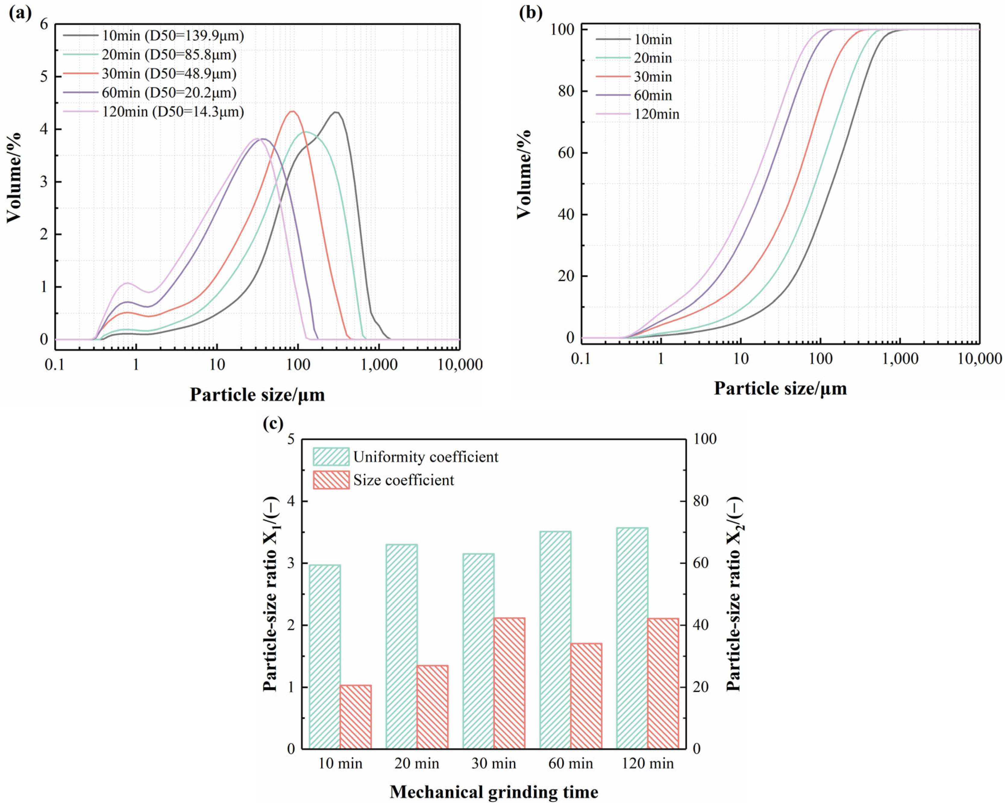
Figure 2a,b illustrate the effect of different mechanical grinding times (10, 20, 30, 60, and 120 min) on the particle size distribution and cumulative particle size distribution of IRS. The results indicate that the particle size of IRS decreases as grinding time gradually increases. After grinding for 120 min, the D50 value was reduced to 14.3 μm. It is worth noting that the grinding efficiency within the first 60 min is relatively high (i.e., the reduction in particle size per unit time is more significant), whereas beyond 60 min, the efficiency decreases markedly. This behavior is primarily due to the Fe-rich phase existed in IRS, which is a mineral that is difficult to grind. Under mechanical grinding, the particle size of this phase reaches a threshold beyond which further refinement becomes challenging. Similar findings have been reported in studies by Zhu et al. [29] and Li et al. [30].
According to previous studies [30,31], Equations (1) and (2) were adopted to calculate the uniformity coefficient and size distribution coefficient of IRS particles subjected to different grinding durations, with the results shown in Figure 2c. It can be observed that both the uniformity coefficient and size distribution coefficient of the IRS particles increase to some extent with prolonged grinding time. This indicates that extended grinding primarily reduces the particle size of the IRS but does not improve the particle uniformity or optimize the size distribution. This phenomenon may be attributed to the presence of significant amounts of refractory phases (e.g., Fe-rich minerals) in the IRS, hindering the further refinement of certain particles.
X 1 = ( D 90 D 10 ) / D 50
X 2 = D 90 / D 10
where D10, D50, and D90 stand for the 10%, 50%, and 90% of the particle size distribution, respectively.
To facilitate the exploration of how IRS particle size affects CSC-based materials, three representative IRS specimens with distinct particle size characteristics were selected from the five different grinding times: 20 min (D50 = 85.8 μm), 30 min (D50 = 48.9 μm), and 120 min (D50 = 14.3 μm). These specimens were labeled as IRS0, IRS1, and IRS2, respectively. Subsequent experiments focused on these three IRS variants with different particle sizes.

3.1.2. Chemical Bond Activity of IRS

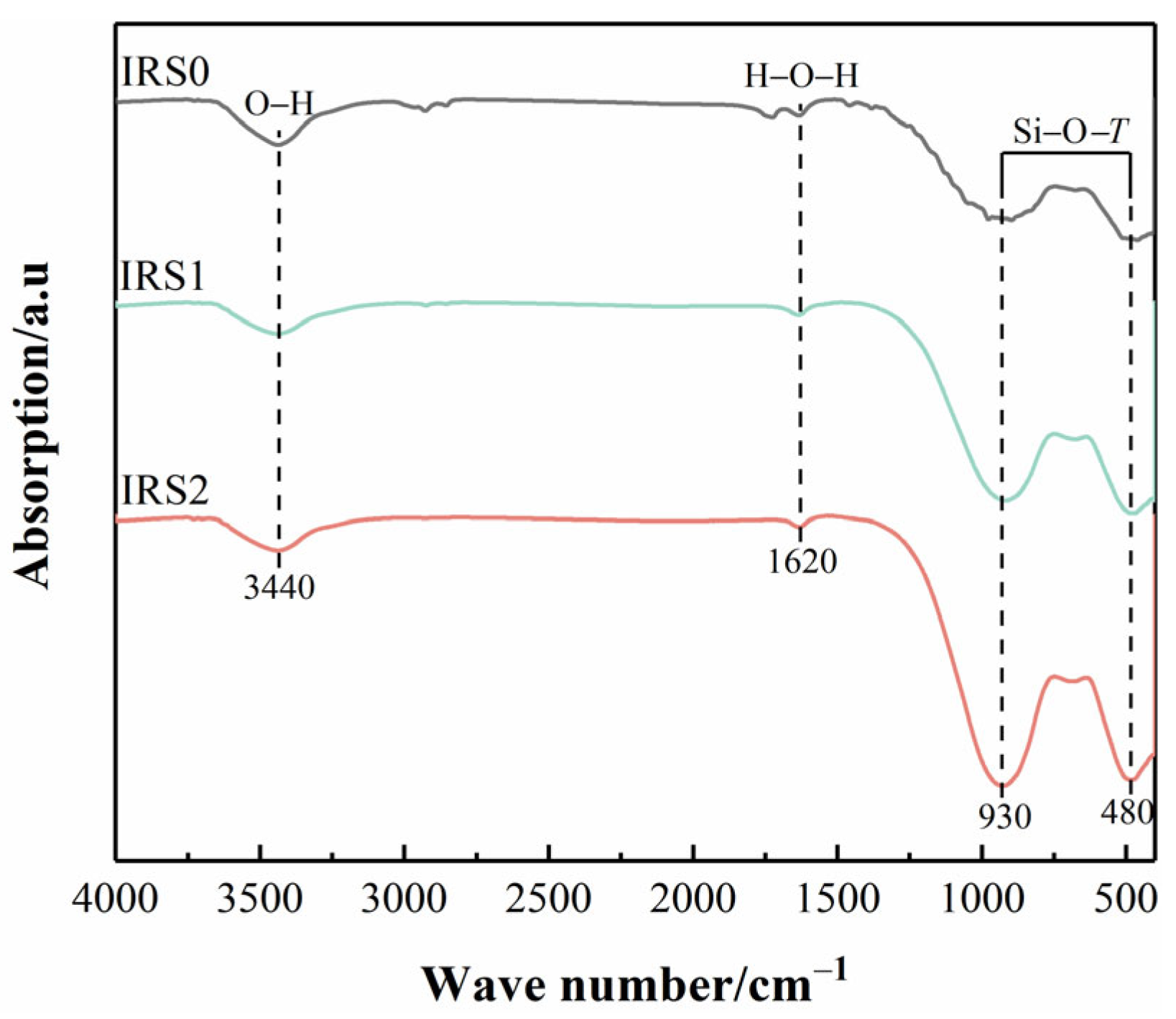
FT-IR was used to characterize the functional groups of IRS0, IRS1, and IRS2, as illustrated in Figure 3, to investigate their chemical bonding activity. The peaks at around 3440 cm−1 and 1620 cm−1 are attributed to the bending vibrations of O−H and H−O−H groups, respectively. The intensities of these peaks showed no obvious change as the grinding time increased, indicating that the chemical bonds associated with O−H and H−O−H groups remain relatively stable and are not markedly affected by mechanical forces. In contrast, the strong absorption bands around 930 and 480 cm−1 are mainly related to the Si−O−T vibrations (where T = Si, Al, or Fe tetrahedral cations) in silicate and aluminate tetrahedral structures [32,33]. The intensity of these vibrations increased noticeably with extended grinding, suggesting a decrease in the degree of polymerization of the silicate and aluminate networks and an increasing disordering of their long-range structure in IRS under mechanical grinding. Consequently, mechanical grinding enhances the bond-breaking activity of IRS, leading to improved hydration reactivity.

3.1.3. Morphological Characteristics of IRS

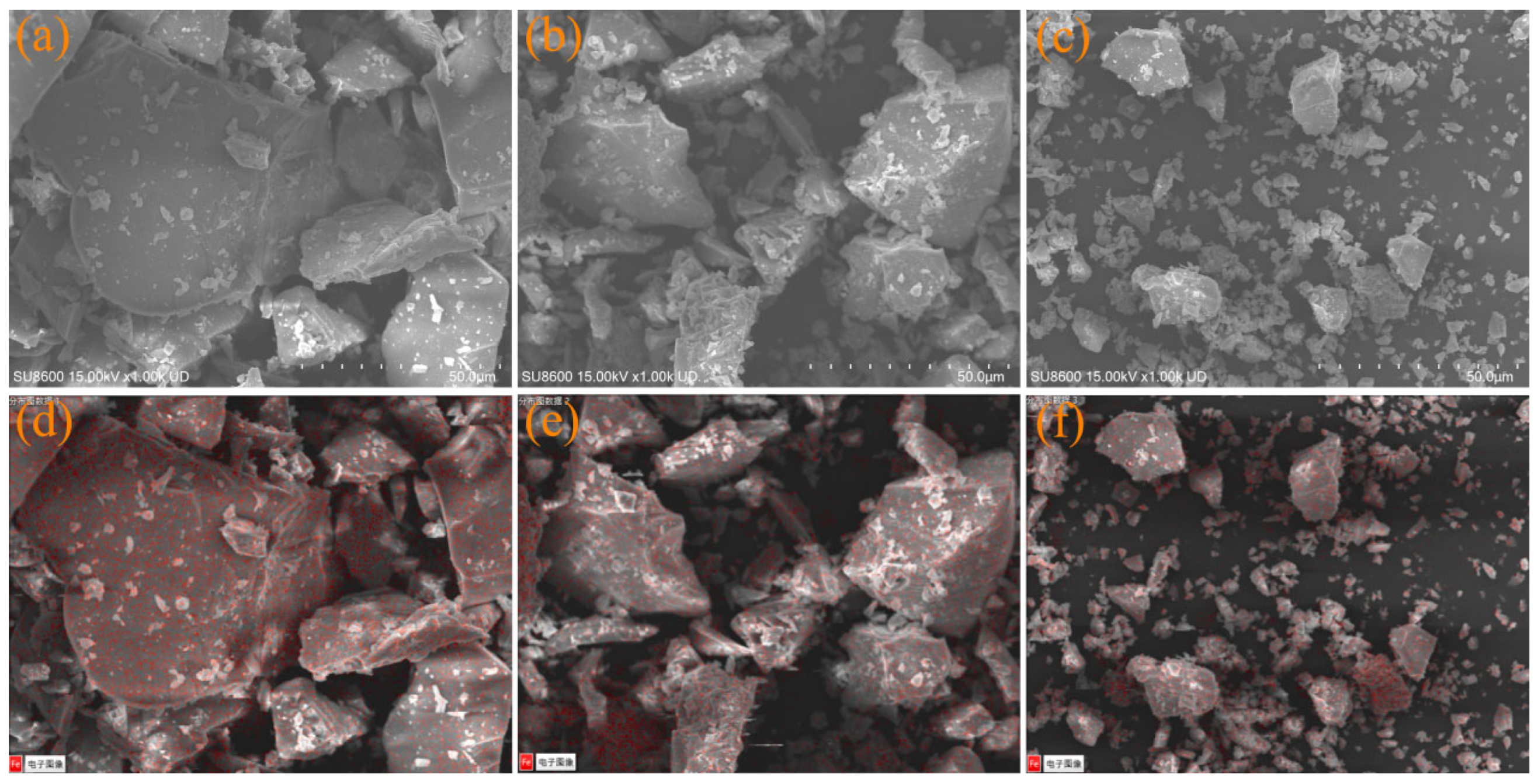
The morphologies of IRS0, IRS1, and IRS2 were characterized using SEM, as shown in Figure 4a–c. It can be seen that the particle size of IRS gradually decreases with extended grinding time. The IRS0 particles exhibit a sub-angular to angular morphology. After further grinding treatment, the edges of some particles are worn down under mechanical force, resulting in a gradually smoother appearance. Furthermore, the approximate particle size information of the various IRS samples can be roughly estimated from the images, which is consistent with the observations described in Section 3.1.1.
The distribution of Fe within the IRS samples was analyzed using EDS, as shown in Figure 4d−f. The results clearly confirm the presence of a significant amount of Fe-phase minerals in IRS. Finer particle sizes allow IRS to increase its contact area with water and cementitious hydrates in CSC-based materials, thereby facilitating the participation of Fe-phase minerals in the hydration reaction.

3.2. Compressive Strength

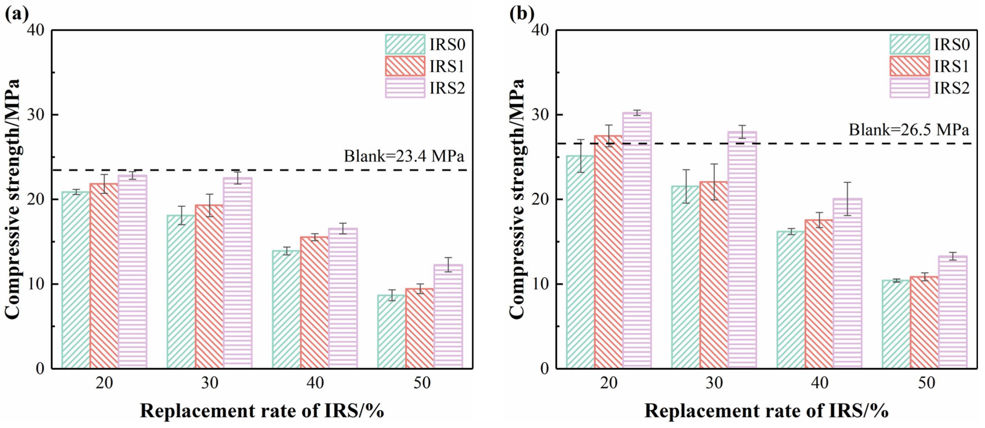
Figure 5a,b illustrate the influence of three types of IRS with different particle sizes on the compressive strength of CSC mortar at 3 d and 28 d. At 3 d, incorporating IRS caused compressive strength to decline to varying degrees, with the most significant reduction observed at a 40% dosage. This is primarily attributed to the notably low early-age reactivity of IRS. The reduction in active components responsible for early strength in CSC (i.e., the dilution effect) consequently weakens the early-age performance. However, the adverse effect of IRS2 on the 3 d compressive strength was less pronounced than that of IRS0 and IRS1. Moreover, when the dosage of IRS2 did not exceed 30%, the compressive strength of the CSC mortar (IRS2/20: 22.8 MPa; IRS2/30: 22.5 MPa) was almost comparable to that of the pure CSC mortar (23.4 MPa). At 28 d, the influence of the three types of IRS on compressive strength showed a trend similar to that at 3 d. Notably, the compressive strengths of IRS1/20, IRS2/20, and IRS2/30 exceeded that of the pure CSC mortar, reaching 27.5 MPa, 30.2 MPa, and 28.0 MPa, respectively. According to previous studies [25,34], Fe-bearing minerals facilitate the transformation of AFt into Fe-bearing AFt within CSC-based materials. Their slower reaction kinetics can effectively mitigate the excessive generation of AFt. In addition, the finer particle size of IRS2 contributes to a dense packing effect, which reduces porosity and thereby enhances strength.
The above results indicate that finely ground IRS2 can significantly contribute to the compressive strength of CSC-based materials. This enhancement is closely associated with its solid-phase composition and microstructural characteristics. Subsequent studies will focus on the IRS2/30 mixture to further investigate the underlying factors influencing the strength development mechanism of CSC-based materials.

3.3. Hydration Heat

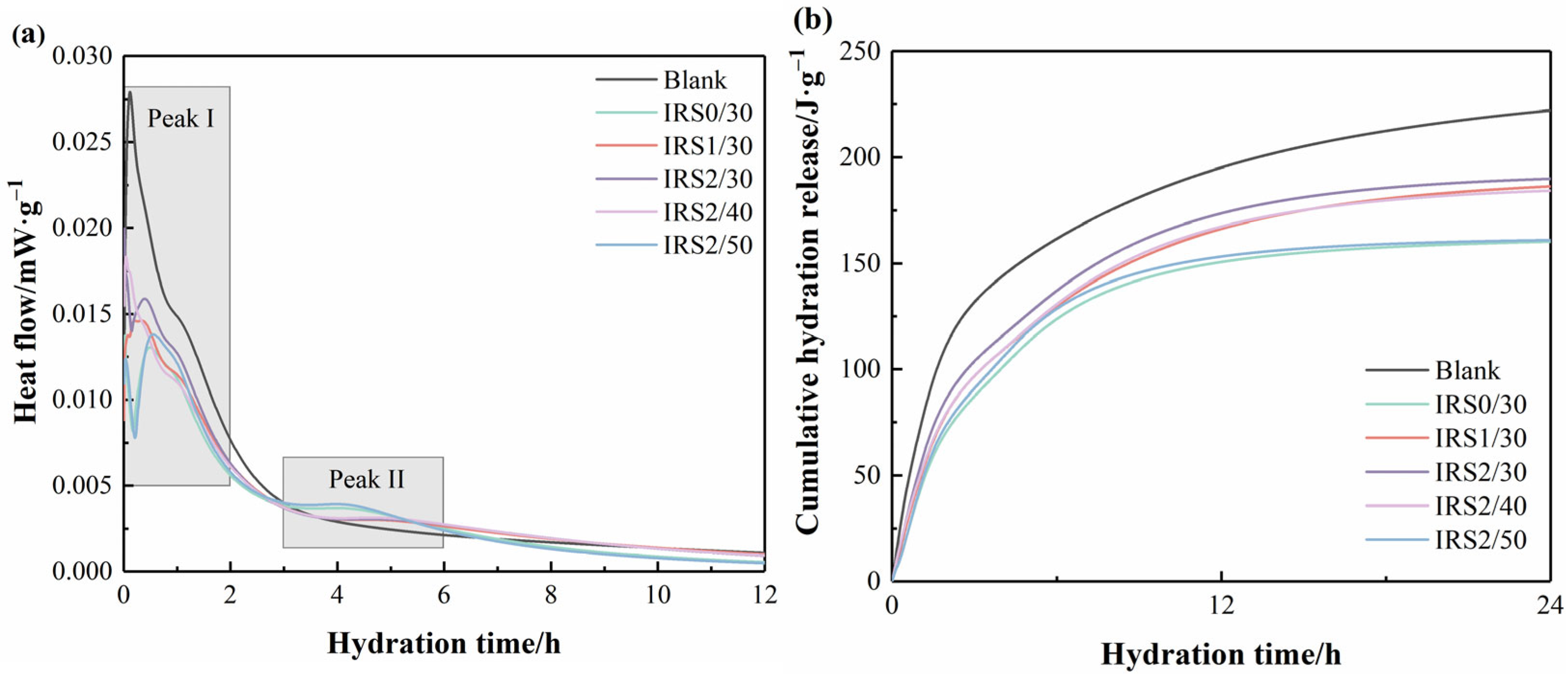
Figure 6 shows the hydration heat flow and cumulative heat release curves of several selected paste specimens. From Figure 6a, it can be observed that, except for the pure CSC paste specimen, all IRS-containing paste specimens exhibit two distinct peaks (namely Peak I and Peak II). This is because the pure CSC paste contains a significant amount of C4A3Š, which reacts rapidly with gypsum and lime to form AFt—releasing a substantial amount of heat during the early hydration stage and thereby resulting in Peak I [35]. Furthermore, the incorporation of IRS reduces the intensity of Peak I and promotes the formation of Peak II. The primary reason is that IRS dilutes the reactive components in CSC, thereby weakening the heat release associated with Peak I. Additionally, the Fe-rich phase in IRS—characterized by slow reaction kinetics—gradually facilitates the formation of Fe-containing hydrates within 3–6 h, leading to the emergence of Peak II.
Figure 6b displays the cumulative hydration heat within the 0–24 h range for several selected paste specimens. By comparing the Blank specimen, IRS2/30, IRS2/40, and IRS2/50, it can be seen that the cumulative heat release decreases as the dosage of IRS2 increases, which is consistent with the heat flow test results. Furthermore, the cumulative hydration heats within 24 h for IRS0/30, IRS1/30, and IRS2/30 are 160.30 J/g−1, 186.39 J/g−1, 189.92 J/g−1, respectively. This trend is because finer IRS particles can expose more reaction sites, significantly accelerating the release rate of Fe3+, which in turn hastens its reaction in CSC-based materials. According to research by Zhang et al. [24], delayed heat release during hydration can lead to a looser microstructure, thereby preserving a higher concentration of soluble ions. These high concentrations of ions may contribute to some extent to compensating for the later-stage microstructure development.

3.4. Solid Phase Analysis

3.4.1. XRD Analysis

The phase composition of paste specimens containing IRS was analyzed using XRD, as shown in Figure 7. The patterns demonstrate the presence of AFt, AFm, unreacted gypsum, calcite (CaCO3), and C2S phases.
At 3 d, as shown in Figure 7a,b, the incorporation of IRS into CSC led to a reduction in the peak intensities of almost all hydrates due to the dilution effect. As the primary early-age hydrate, AFt plays a decisive role in the early strength development of CSC-based materials [36,37]. It can be seen that the AFt peaks of IRS2/30 are higher than those of IRS0/30 and IRS1/30, indicating that IRS2 promotes the formation of early-age AFt more significantly compared to IRS0 and IRS1. Additionally, the peak intensities of CaCO3 and C2S in these samples showed no significant changes. At 28 d, as shown in Figure 7c,d, the types of hydrates remained almost unchanged compared to those at 3 d. However, the AFt diffraction peak intensities of IRS2/30 and IRS1/30 were similar and higher than that of IRS0/30, suggesting that at later hydration ages, IRS1 promotes the formation of AFt in CSC-based materials to an extent comparable to that of IRS2. It is worth noting that the highest peak intensity of CaCO3 was observed in IRS2/50, indicating significant carbonation during the curing process, which may be related to its pore structure (the increase in IRS content may have led to increased porosity).

3.4.2. TG/DTG Analysis

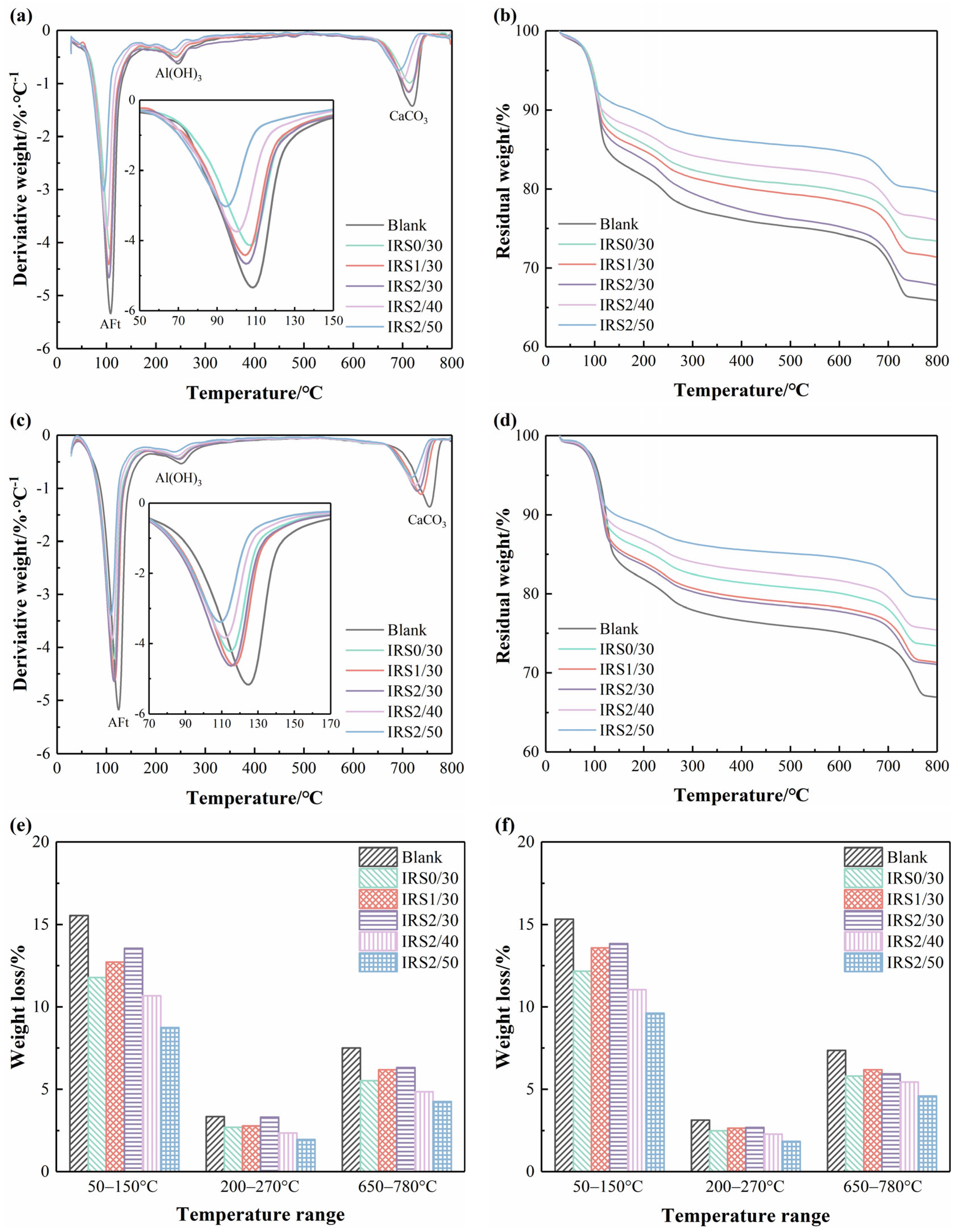
The hydrate content and thermal stability of paste specimens containing IRS were quantitatively analyzed using TG/DTG, as shown in Figure 8. During the heating process from 30 °C to 800 °C, three distinct thermal decomposition peaks were observed. Among them, the mass loss peaks in the ranges of 50−150 °C and 200−270 °C correspond to the dehydration and decomposition of AFt and Al(OH)3 (AH3), respectively, while the endothermic peak between 650−780 °C represents the decomposition of CaCO3 [38,39]. The quantitative results obtained from TG curves are displayed in Figure 8e,f.
At 3 d, as shown in Figure 8a,b, the mass losses in the range of 50−150 °C for IRS0/30, IRS1/30, and IRS2/30 were 11.78%, 12.72%, and 13.55%, respectively. This indicates that reducing the particle size of IRS effectively promotes the early formation of AFt in CSC-based materials, as mass loss in this temperature range is primarily attributed to the dehydration of AFt. This finding aligns with the results derived from XRD analysis. AH3 is mainly generated from the hydration of C4A3Š; the increase in AH3 content with decreasing IRS particle size suggests that finer IRS enhances the hydration reactivity of CSC. At 28 d, as shown in Figure 8c,d, the mass loss trends in the 50−150 °C range were similar to those at 3 d. However, the mass loss of IRS1/30 (13.58%) in this temperature interval was close to that of IRS2/30 (13.84%). This phenomenon indicates that the sensitivity of AFt content to IRS fineness decreases at later hydration ages compared to the early stage. Furthermore, regardless of the fineness and dosage of IRS, its incorporation reduced the CaCO3 content in CSC-based materials—implying that IRS has a possible positive effect on the carbonation resistance of CSC-based materials.
It is noteworthy that a distinct phenomenon was observed in the DTG curves: the mass loss peak of AFt shifted toward lower temperatures after the incorporation of IRS, especially during the later hydration stages. According to Chang et al. [23] and Ba et al. [38], the incorporation of heavy metal ions into the AFt structure can reduce its crystallinity. Therefore, the observed low-temperature shift in the AFt mass loss peak may be attributed to the extensive substitution of Al3+ by Fe3+ derived from IRS.

3.5. Microstructure

3.5.1. SEM

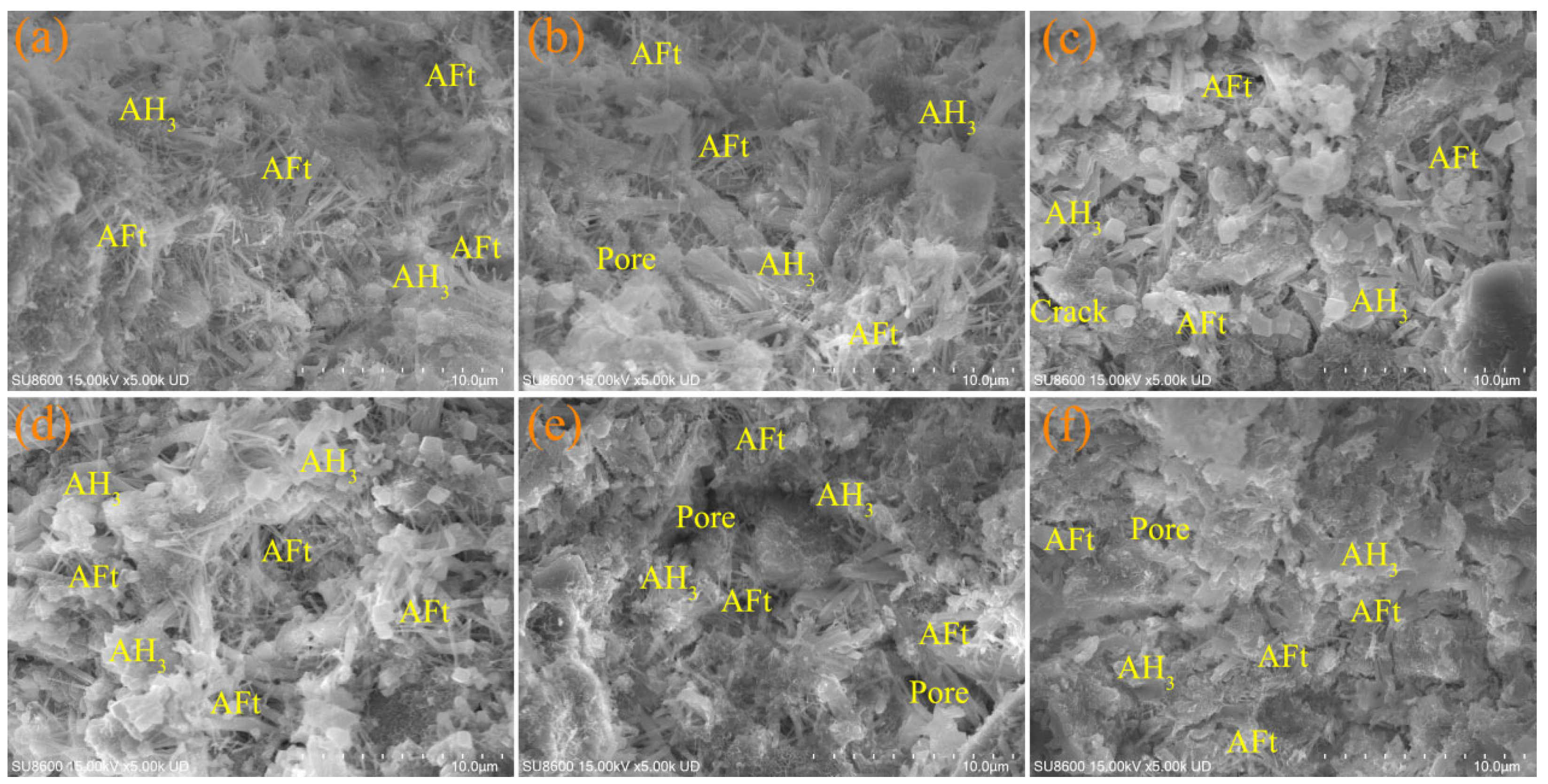
Figure 9 and Figure 10 illustrate the morphological characteristics of hydrates in IRS-containing paste specimens at 3 d and 28 d, respectively. The results show that the hydrates mainly consist of a large quantity of AFt crystals, AH3, and some pores.
At 3 d, a substantial quantity of needle-shaped AFt crystals, platelet-like AH3, and some gel hydrates were observed. These constitute the primary hydrates that form the early-age microstructure of CSC-based materials, which is consistent with the findings in Section 3.4.2. At the 30% dosage, a greater number of AFt crystals were observed in the IRS0/30, IRS1/30, and IRS2/30 specimens, as shown in Figure 9b−d. However, the crystal size decreased slightly with the reduction in IRS fineness. Furthermore, as the dosage of IRS2 increased, the number of observable AFt crystals decreased—this is mainly attributed to the high replacement ratio of CSC by IRS2.
At 28 d, as shown in Figure 10, IRS2/30 exhibited a denser microstructure compared to IRS0/30 and IRS1/30—an important factor contributing to its superior 28 d compressive strength. In contrast, specimens with a higher IRS2 dosage (IRS2/40 and IRS2/50) showed a more porous overall structure, indicating that even the finer particle size of IRS2 could not compensate for the reduction in structural density caused by excessive incorporation. It is worth noting that SEM observations alone did not allow direct determination of the influence of Fe3+ introduced by IRS on the internal chemical structure of AFt. Therefore, further analysis using EDS will be conducted to examine the detailed structure of the hydrates.

3.5.2. EDS

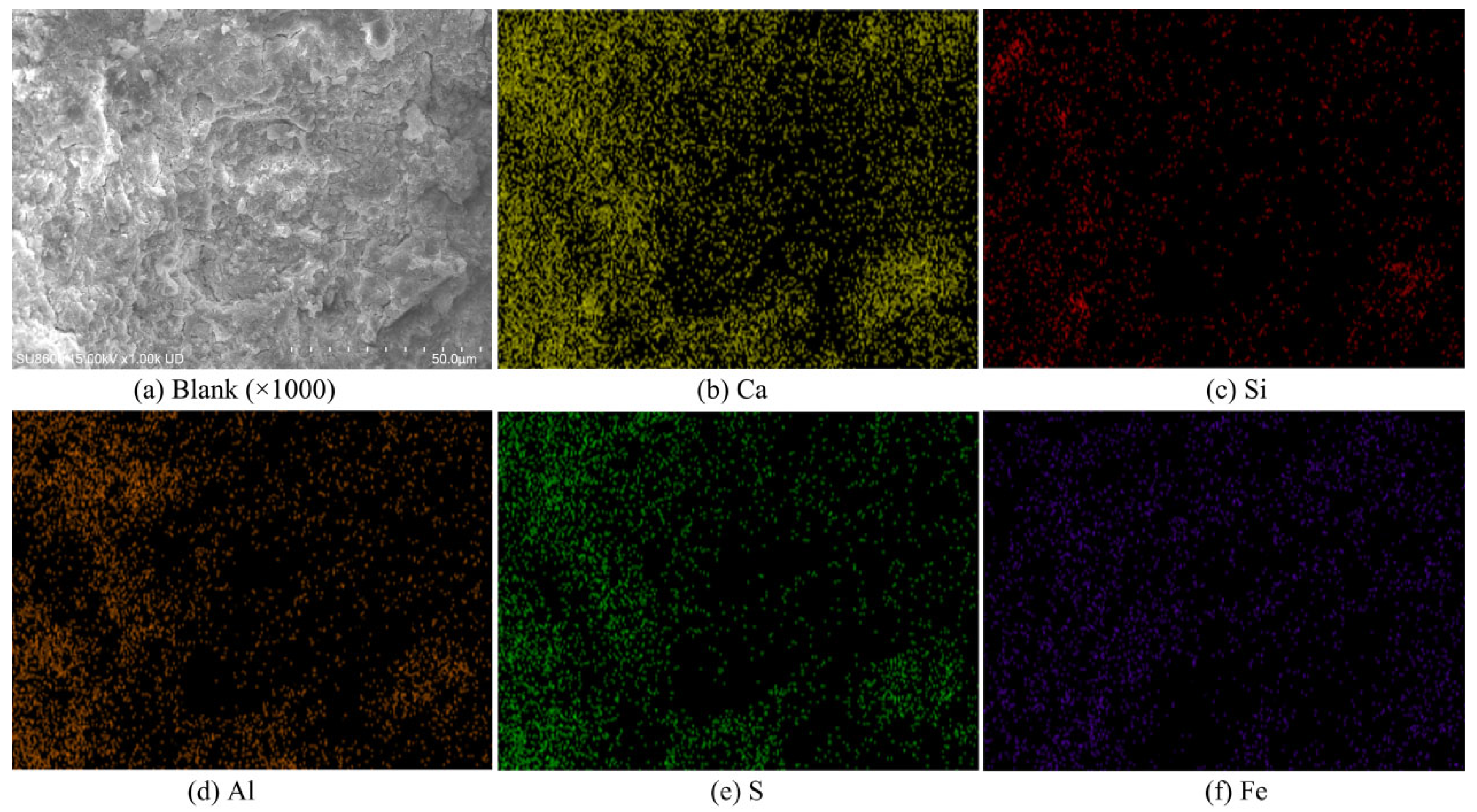
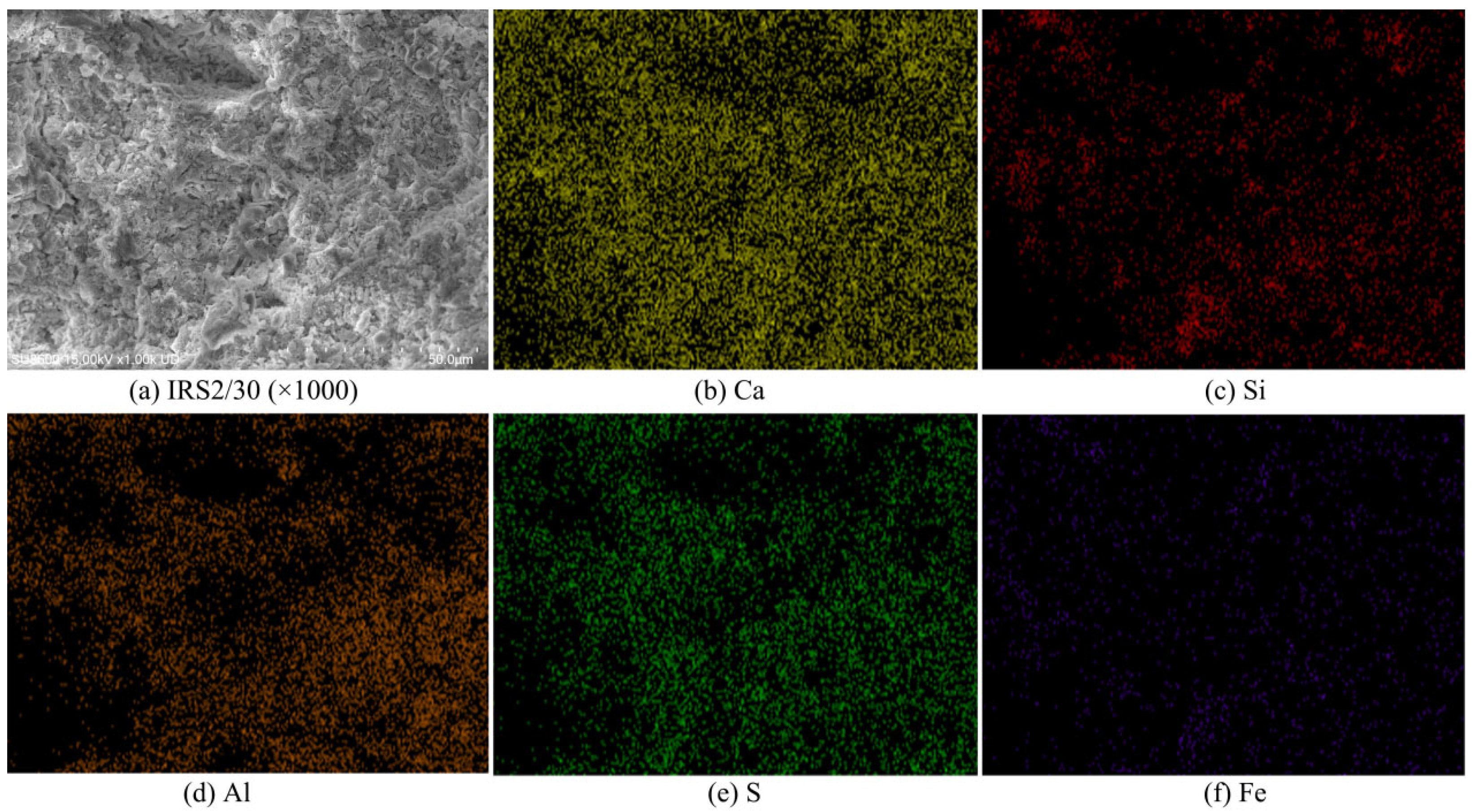
To elucidate the influence of Fe3+ from IRS on hydrates, EDS was conducted at low magnification (×1000) to characterize the chemical elemental distributions of the Blank and IRS2/30 specimens, as shown in Figure 11 and Figure 12. The results indicate that Ca, Si, Al, S, and Fe are the major constituent elements. Among these, Ca, Al, and S are primarily derived from the hydrates of C4A3Š, namely AFt and AH3. Si mainly originates from the hydrate of C2S—C−S−H gel. Fe is mainly attributed to Fe-bearing AFt and unreacted IRS particles. The elemental composition measurements of the Blank and IRS2/30 specimens are summarized in Table 4. The data show a higher Fe content in the IRS2/30 specimen, which may consequently affect the structural composition of AFt.
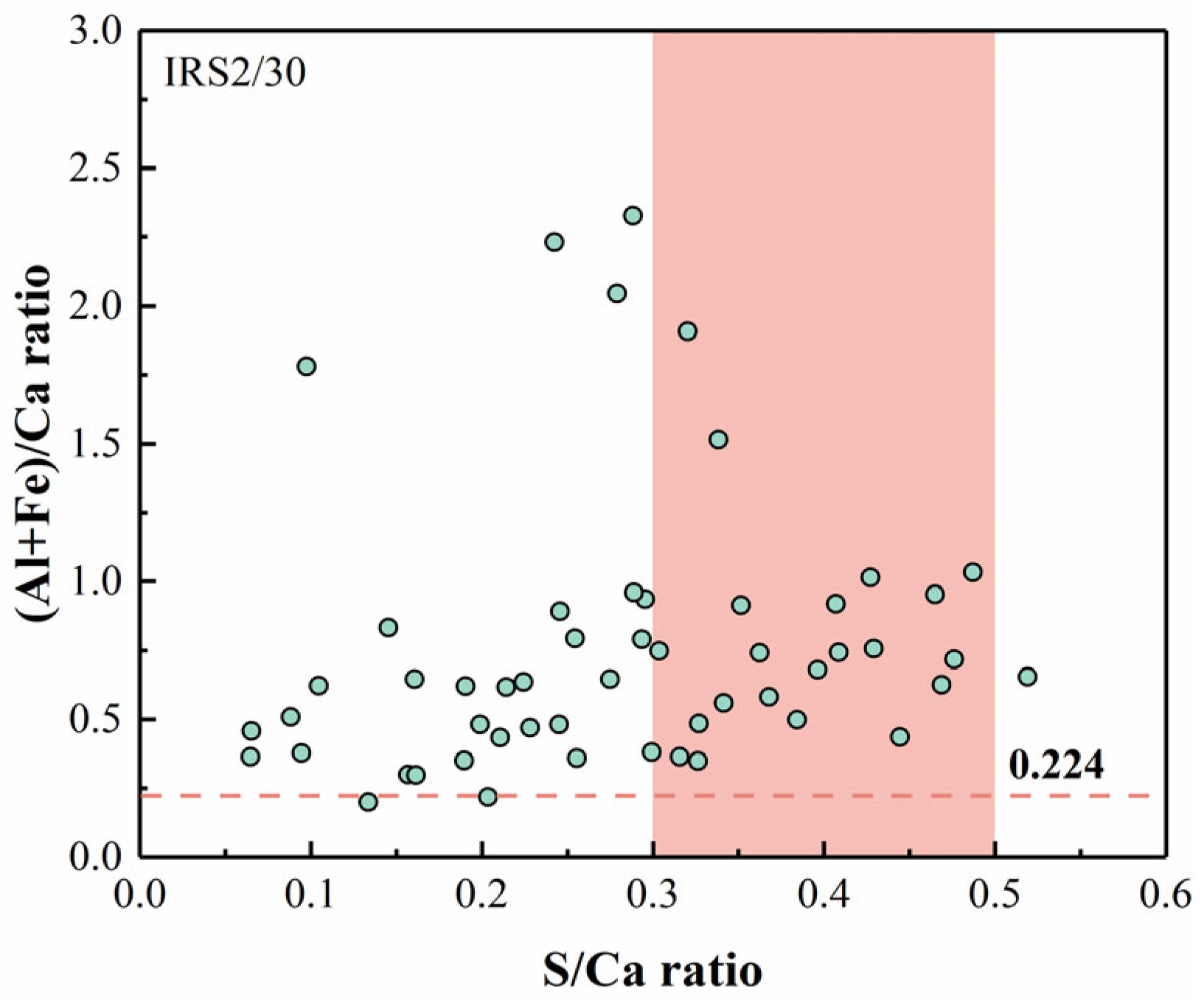
According to Zhang et al. [24] and Bouibes et al. [40], Fe3+ and Al3+ have comparable ionic sizes and identical valence states (+3 charge), which suggests that incorporating IRS may cause Fe3+ to substitute for Al3+ in AFt. To further investigate this phenomenon, EDS were performed at no fewer than 50 locations with typical AFt morphology in the IRS2/30 to determine the elemental composition ratios. Based on previous literature [22,24], the theoretical molar ratios of S/Ca and Al/Ca in pure Al-AFt (Al-rich AFt) are 1:2 and 1:3, respectively, corresponding to mass ratios of 0.4 and 0.224. Considering the isomorphic substitution of Al3+ by Fe3+, the theoretical mass ratios of S/Ca and Fe/Ca in pure Fe-AFt (Fe-rich AFt) would be 0.4 and 0.465, respectively. Therefore, the extent of Fe3+ substitution for Al3+ in AFt was evaluated by plotting S/Ca versus (Al + Fe)/Ca, as shown in Figure 13. The region with an S/Ca ratio between 0.3 and 0.5 was defined as the range most consistent with the theoretical stoichiometry of AFt. It was observed that all detected (Al + Fe)/Ca ratios exceeded 0.224, indicating partial to complete substitution of Al3+ by Fe3+ (derived from IRS) in the AFt structure. Notably, although many EDS measurement points exhibited (Al + Fe)/Ca ratios higher than the theoretical value of 0.465, this deviation may be attributed to the inclusion of high-Fe IRS particles within the EDS detection areas.

3.6. Discussion

Based on the characterization results of particle size distribution, FT-IR, and SEM/EDS for IRS with different grinding times, it is demonstrated that mechanical grinding reduces the particle size of IRS and enhances its chemical bond activity. However, mechanical grinding did not significantly improve the particle uniformity of IRS. Due to the presence of a substantial amount of refractory phases (i.e., Fe-containing minerals) in IRS, there exists a limiting threshold for particle size reduction—consistent with previous studies [30,41]. Furthermore, the increased reactivity of IRS achieved via mechanical grinding helps mitigate the strength loss caused by its high-volume replacement of CSC. Specifically, IRS2 at a 30% dosage exhibited a 28 d compressive strength comparable to that of the pure CSC mortar (Blank: 26.5 MPa; IRS2/30: 28.0 MPa).
CSC is extensively used in rapid repair projects owing to its high early-age reactivity. However, its intense heat release during hydration and limited long-term strength development remain critical constraints on its broader application [42,43]. This study demonstrates that the high-volume incorporation of IRS effectively reduces the hydration heat release of CSC-based materials while significantly promoting their later-age strength development. These findings have significant implications for expanding the applicability of CSC-based materials in practical engineering scenarios. Although the influence of iron-rich solid waste on AFt in cementitious systems has been reported in some studies [15,17,40], AFt remains the primary hydrate in CSC-based systems—and its performance evolution exerts a profound impact on the overall properties of CSC-based materials. Therefore, the core issue to be addressed in this study is how the iron-rich phases in IRS modify the performance of CSC-based materials, with the underlying mechanism elucidated via multiple analytical techniques.
Solid-phase analysis indicates that increasing the fineness of IRS promotes the formation of AFt in CSC-based materials, enhances the degree of hydration of CSC, and improves the carbonation resistance of the resulting composites. As confirmed by TG/DTG and EDS analyses (see Section 3.4.2 and Section 3.5.2), the Fe3+ in IRS facilitates the conversion of Al-AFt to Fe-AFt in CSC. According to previous studies [24,25], the isomorphic substitution of Al3+ by Fe3+ in AFt induces notable changes in the strength development process and hydrate formation of CSC-based materials. Based on these observations, the following conclusions can be summarized: (1) Compared to Al-AFt, Fe-AFt exhibits slower reaction kinetics, which favors the formation of a more stable skeletal structure when combined with other hydrates (e.g., C–S–H gel). (2) The larger ionic radius of Fe3+ relative to Al3+ contributes to a more stable crystalline structure of Fe-AFt, which may enhance the volumetric stability and durability of CSC-based materials. Notably, the analytical techniques employed in this study (EDS and TG) are insufficient to provide definitive evidence for the substitution of Al3+ by IRS-derived Fe3+ in the AFt structure. Further investigation utilizing analytical methods such as Mössbauer spectroscopy, X-ray Photoelectron Spectroscopy, or Nuclear Magnetic Resonance is therefore recommended to substantiate this conclusion and confirm the substitution mechanism. In recent years, data-driven approaches such as machine learning have emerged as powerful tools for understanding and predicting the key properties of cement-based materials, with numerous applications across other civil engineering domains, e.g., structural health monitoring and material design [44,45]. However, although this study primarily employs conventional experimental methods, the experimental data generated herein can provide a valuable foundation for machine learning models aimed at predicting the grinding processes proposed in this work or forecasting the long-term performance of CSC-based materials.
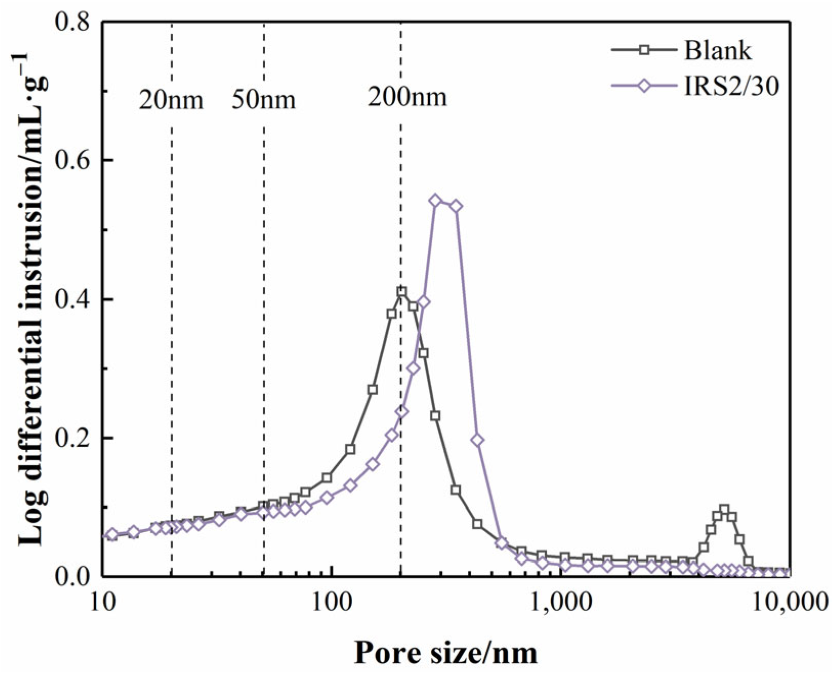
MIP was used to compare the pore size distributions of the blank and the IRS2/30 at 28 d, as shown in Figure 14. Generally speaking, pores in cement-based materials smaller than 50 nm cause minimal damage to mechanical properties, whereas those exceeding this size can significantly compromise performance. The results reveal that the pore size distribution curve of IRS2/30 shifted toward larger pore sizes compared to that of the blank. Nevertheless, IRS2/30 still maintained a 28 d compressive strength comparable to that of Blank. This observation further confirms the beneficial contribution of Fe-AFt to the late-age strength of CSC-based materials.
This study proposes a sustainable strategy for utilizing IRS—a representative solid waste from the non-ferrous metallurgical industry—in CSC. This approach not only effectively enhances the performance of CSC-based materials but also demonstrates the green utilization potential of such non-traditional solid wastes. It is noteworthy that a comprehensive evaluation of the benefits of IRS incorporation in CSC-based materials requires further investigation into their long-term performance. Therefore, subsequent research will focus on the evolution of long-term properties of IRS-containing CSC-based materials and their durability under special environmental conditions (e.g., freeze-thaw cycles, chloride ion erosion, or sulfate attack).

4. Conclusions

This study investigated the performance of CSC-based materials, including compressive strength, hydration, and microstructure, after incorporating IRS with different particle sizes. The following conclusions can be drawn:
(1)
Mechanical grinding effectively reduced the particle size of IRS. The D50 of IRS decreased to 85.8 μm, 48.9 μm, and 14.3 μm with grinding times of 20 min, 30 min, and 120 min, respectively. Although prolonged grinding did not improve the uniformity of IRS particles or optimize the size distribution, it significantly increased the contact area between IRS and other hydrates, thereby enhancing its reactivity.
(2)
Under the impact of the dilution effect, incorporating IRS reduces the 3 d compressive strength of CSC mortar. However, when the content of IRS2 does not exceed 30%, the 28 d compressive strength of these CSC mortars becomes comparable to that of the pure CSC mortar. Specifically, the IRS2/30 achieved a 28 d compressive strength of 28.0 MPa.
(3)
The incorporation of IRS reduced the hydration heat release of CSC. A decrease in IRS particle size exposed more reactive sites, which in turn accelerated the release efficiency of Fe3+. Moreover, increasing the fineness of IRS effectively promoted the hydration of C4A3Š in CSC, facilitated the formation of AFt and AH3, and enhanced the overall degree of hydration of CSC.
(4)
Increasing the fineness of IRS contributed to a denser microstructure in CSC-based material, especially at 28 days. EDS analyses indicated the potential substitution of Al3+ by Fe3+ in AFt, which is hypothesized to influence the strength development of CSC-based materials. However, further advanced characterization is required to confirm the extent and mechanism of this substitution.

Author Contributions

Conceptualization, H.L. (Huawei Li); methodology, R.W.; formal analysis, X.Y.; investigation, X.Y. and H.L. (Haixing Liu); resources, C.P. and T.W.; data curation, H.L. (Haixing Liu) and R.W.; writing—original draft preparation, R.W.; writing—review and editing, R.W. and H.L. (Huawei Li); supervision, X.Y.; visualization, C.P.; project administration, H.L. (Haixing Liu), X.Y., T.W. and C.P.; funding acquisition, T.W. and H.L. (Huawei Li). All authors have read and agreed to the published version of the manuscript.

Funding

The authors gratefully acknowledge the financial support provided by the Natural Science Foundation of Fujian Province (Grant Nos. 2024J01912 and 2023J011044).

Data Availability Statement

The raw data supporting the conclusions of this article will be made available by the authors on request.

Acknowledgments

The authors extend their gratitude to Scientific Compass (www.shiyanjia.com) for providing invaluable assistance with the hydration heat analysis with the service accessed on 15 April 2025.

Conflicts of Interest

The authors declare no conflicts of interest.

References

  1. Xin, X.; Duan, G.; Huang, Y.; Li, J.; Li, C.; Hou, P. Study on the hydration of slag-belite calcium sulfoaluminate-Portland cement composite cementitious system. Constr. Build. Mater. 2024, 433, 136713. [Google Scholar] [CrossRef]
  2. Chen, J.; Xie, B.; Lu, Z.; He, S.; Ma, S. Early hydration characteristics and kinetics model of ordinary portland cement-calcium sulfoaluminate cement composites. Materials 2025, 18, 2559. [Google Scholar] [CrossRef] [PubMed]
  3. Zhao, J.; Wang, Z.; Xiao, M.; Cui, C.; Liu, H. Utilization of marine-dredged sediment and calcium sulfoaluminate cement for preparing non-sintered ceramsites: Properties and microstructure. J. Mar. Sci. Eng. 2025, 13, 891. [Google Scholar] [CrossRef]
  4. Sun, H.; Lin, T.; Zhuo, K.; Qian, J.; Chen, X.; Zhang, J.; Sun, Y. Sulfate optimization in ettringite rich cements by SO3/Al2O3 molar ratio: A comparative study of calcium sulfoaluminate and aluminate cements. Case Stud. Constr. Mater. 2024, 21, e03701. [Google Scholar] [CrossRef]
  5. Tchekwagep, J.J.K.; Li, Z.; Shifeng, H.; Huang, J.; Tchakouté, H.K. Transforming waste into sustainable insulation: A novel thermal insulation board utilizing treated rice husk ash, bagasse ash, and expanded vermiculite in calcium sulfoaluminate cement composite. J. Clean. Prod. 2025, 512, 145699. [Google Scholar] [CrossRef]
  6. Ndiaye, K.; Samson, G.; Ginestet, S.; Rouviere, Y.; Cyr, M. Foamed calcium sulfoaluminate cement with controlled porous network for daily or seasonal heat storage in ettringite. J. Build. Eng. 2024, 98, 111284. [Google Scholar] [CrossRef]
  7. Leone, M.; Blasi, G.; Colonna, D. Long-term flexural response of reinforced calcium sulfoaluminate/cement concrete beams. Eng. Struct. 2023, 292, 116585. [Google Scholar] [CrossRef]
  8. Qiu, X.; Chen, W.; Yuan, J.; Zhang, Z.; Wu, G. Study on seawater corrosion resistance of calcium sulfoaluminate cement-based novel grouting materials. Mater. Lett. 2024, 366, 136509. [Google Scholar] [CrossRef]
  9. Cai, X.; Yang, D.; Zhang, D.; Cui, J.; Wang, W.; Liu, L. Development of high-early-strength low-carbon engineered cementitious composites with calcium sulfoaluminate cement incorporating high-volume fly ash. Case Stud. Constr. Mater. 2023, 18, e01959. [Google Scholar] [CrossRef]
  10. Li, H.; Liu, F.; Pan, Z.; Li, H.; Wu, Z.; Li, L.; Xiong, Z. Use of supplementary cementitious materials in seawater–sea sand concrete: State-of-the-art review. Constr. Build. Mater. 2024, 425, 136009. [Google Scholar] [CrossRef]
  11. Seo, J.; Park, S.; Kim, N.; Yoon, H.N.; Kim, S.; Bae, J.-H.; Jang, D.; Cho, A.; Lee, H.K. Characterization of hydrates in quaternary Portland cement-blast furnace slag-calcium sulfoaluminate clinker-limestone or gypsum systems: Experimental and thermodynamic modeling approaches. Cem. Concr. Compos. 2025, 162, 106126. [Google Scholar] [CrossRef]
  12. Alsaif, A.; Fares, G.; Alhozaimy, A. Effectiveness of ultra-high-performance concrete containing recycled tire steel fibers and high-volume scoria rock powder as natural pozzolan. Case Stud. Constr. Mater. 2024, 21, e03841. [Google Scholar] [CrossRef]
  13. Khamseh, B.; Shourijeh, P.T.; Binesh, S.M. Strength and deformation characteristics of cement-stabilized Fe-rich fine iron ore tailings. Constr. Build. Mater. 2025, 463, 140101. [Google Scholar] [CrossRef]
  14. Zeng, H.; Ramanathan, S.; Kim, H.J. Effect of copper mine tailings and copper slag on the hydration, microstructure, and mechanical property in Portland cement. Results Eng. 2025, 26, 104890. [Google Scholar] [CrossRef]
  15. Astoveza, J.; Trauchessec, R.; Migot-Choux, S.; Soth, R.; Pontikes, Y. Iron-rich slag addition in ternary binders of Portland cement, aluminate cement and calcium sulfate. Cem. Concr. Res. 2022, 153, 106689. [Google Scholar] [CrossRef]
  16. Astoveza, J.; Trauchessec, R.; Soth, R.; Pontikes, Y. Properties of calcium aluminate blended cement incorporating iron-rich slag: Evolution over a curing period of 1 year. Constr. Build. Mater. 2021, 282, 122569. [Google Scholar] [CrossRef]
  17. Liu, K.; He, B.; Wang, X.; Wang, L.; Jin, J.; Han, P.; Bai, X. Fabrication of iron-rich copper slag cement using low-concentration phosphoric acid as medium: Workability and mechanism. J. Build. Eng. 2025, in press. [Google Scholar] [CrossRef]
  18. Hallet, V.; Pedersen, M.T.; Lothenbach, B.; Winnefeld, F.; De Belie, N.; Pontikes, Y. Hydration of blended cement with high volume iron-rich slag from non-ferrous metallurgy. Cem. Concr. Res. 2022, 151, 106624. [Google Scholar] [CrossRef]
  19. Beersaerts, G.; Soete, J.; Giels, M.; Eykens, L.; Lucas, S.; Pontikes, Y. 3D printing of an iron-rich slag based hybrid mortar. A durable, sustainable and cost-competitive product? Cem. Concr. Compos. 2023, 144, 105304. [Google Scholar] [CrossRef]
  20. Lyu, K.; Qu, Y.; Liu, X.; Kou, F.; Xie, X.; Shi, J.; Shah, S.P. Mechanical activation of MSWIFA: Performance trade-offs between electric grinding and ball milling. Constr. Build. Mater. 2025, 493, 143110. [Google Scholar] [CrossRef]
  21. Jin, Z.; Wang, C.; Cui, C.; Su, Y.; He, X.; Zhi, Z.; Chen, S.; Yang, C.; Guan, S. Effect of ground granulated blast-furnace slag slurries by wet-grinding on the mechanical properties and hydration process of hemihydrate phosphogypsum. Mater. Today Commun. 2024, 41, 111006. [Google Scholar] [CrossRef]
  22. Zhong, H.; Yang, L.; Wang, F. Properties of (Al, Fe)-ettringite solid solution: Experiment, atomic simulation, and thermodynamics modeling. Cem. Concr. Res. 2024, 182, 107556. [Google Scholar] [CrossRef]
  23. Chang, J.; Zeng, T.; Li, J. Influence of iron substitution on the microstructure and properties of ettringite in calcium sulfoaluminate cement: A comprehensive study on the Al/(Fe+Al) ratios. J. Build. Eng. 2024, 86, 108855. [Google Scholar] [CrossRef]
  24. Zhang, M.; Chen, B.; Zhu, W. Performance and hydration mechanisms of ultrafine iron ore tailings enhanced supersulfated cement with high phosphogypsum content. Cem. Concr. Compos. 2025, 157, 105891. [Google Scholar] [CrossRef]
  25. Wang, Z.; Sun, T.; Ouyang, G.; Li, Z.; Deng, Y. Enhancement of polyferric sulphate on the carbonation resistance of phosphogypsum-based excess-sulphate slag cement: Focus on iron-doped ettringite and microstructure alteration. Constr. Build. Mater. 2025, 494, 143224. [Google Scholar] [CrossRef]
  26. Bertola, F.; Gastaldi, D.; Canonico, F.; Paul, G. CSA and slag: Towards CSA composite binders. Adv. Cem. Res. 2018, 31, 147–158. [Google Scholar] [CrossRef]
  27. GB/T 17671-2021; Test Method of Cement Mortar Strength (ISO Method). Standardization Administration of China: Beijing, China, 2021.
  28. JC/T 958-2005; Flow Table for Determine Mortar Fluidity. Standardization Administration of China: Beijing, China, 2005.
  29. Zhu, H.; Ma, M.; He, X.; Zheng, Z.; Su, Y.; Yang, J.; Zhao, H. Effect of wet-grinding steel slag on the properties of Portland cement: An activated method and rheology analysis. Constr. Build. Mater. 2021, 286, 122823. [Google Scholar] [CrossRef]
  30. Li, H.-W.; Wang, R.; Wei, M.-W.; Lei, N.-Z.; Sun, H.-X.; Fan, J.-J. Mechanical properties and hydration mechanism of high-volume ultra-fine iron ore tailings cementitious materials. Constr. Build. Mater. 2022, 353, 129100. [Google Scholar] [CrossRef]
  31. Kotake, N.; Kuboki, M.; Kiya, S.; Kanda, Y. Influence of dry and wet grinding conditions on fineness and shape of particle size distribution of product in a ball mill. Adv. Powder Technol. 2011, 22, 86–92. [Google Scholar] [CrossRef]
  32. Hu, Z.; Gu, X.; Li, Z.; Hu, Z.; Liu, J.; Wang, S.; Wang, H. Sustainable valorization of coal gasification slag through optimized grinding kinetics: Composite cement compressive strength enhancement and environmental assessment. Environ. Res. 2025, 277, 121601. [Google Scholar] [CrossRef]
  33. Gu, X.; Hu, Z.; Hu, Z.; Li, Z.; Liu, J.; Ge, X.; Wang, H. Coal gasification slag-based composite cement under the regulation of grinding speed grinding kinetics: Parameter optimization, hydration mechanism and properties analysis. Adv. Powder Technol. 2025, 36, 105029. [Google Scholar] [CrossRef]
  34. Möschner, G.; Lothenbach, B.; Winnefeld, F.; Ulrich, A.; Figi, R.; Kretzschmar, R. Solid solution between Al-ettringite and Fe-ettringite (Ca6[Al1−xFex(OH)6]2(SO4)3·26H2O). Cem. Concr. Res. 2009, 39, 482–489. [Google Scholar] [CrossRef]
  35. Huang, Y.; Qian, J.; Lu, L.; Zhang, W.; Wang, S.; Wang, W.; Cheng, X. Phosphogypsum as a component of calcium sulfoaluminate cement: Hazardous elements immobilization, radioactivity and performances. J. Clean. Prod. 2020, 248, 119287. [Google Scholar] [CrossRef]
  36. Jacques, K.T.J.; Fengzhen, Y.; Shoude, W.; Piqi, Z.; Shifeng, H.; Xin, C. Analysis of the phases and functions of the various compounds of calcium sulfoaluminate cement after exposure to high temperature. J. Mater. Res. Technol. 2023, 25, 4154–4170. [Google Scholar] [CrossRef]
  37. Yang, Z.; Xue, N.; Xu, L.; Yu, L.; Huang, L.; Wu, K. Evaluation of the efflorescence resistance of calcium sulfoaluminate cement mortar: From indoor accelerated testing to outdoor exposure. J. Mater. Res. Technol. 2023, 22, 2447–2461. [Google Scholar] [CrossRef]
  38. Ba, M.; Xie, J.; Ma, X.; Ma, H.; Ren, X.; Lin, R.; Shen, Y. Effects of secondary aluminum ash sintered ground powder on properties of calcium sulfoaluminate cement-based grouting materials. Constr. Build. Mater. 2025, 462, 140015. [Google Scholar] [CrossRef]
  39. Tanguler-Bayramtan, M.; Turk, S.; Yaman, I.O. Hydration characteristics of calcium sulfoaluminate cements synthesized using an industrial symbiosis framework. Constr. Build. Mater. 2024, 447, 138090. [Google Scholar] [CrossRef]
  40. Bouibes, A.; Laanaiya, M.; Lacarrière, L. Microscopic effect of iron dosage on the stability of Fe-doped ettringite. J. Am. Ceram. Soc. 2024, 107, 5127–5138. [Google Scholar] [CrossRef]
  41. Wang, Y.; He, X.; Su, Y.; Yang, J.; Strnadel, B.; Wang, X. Efficiency of wet-grinding on the mechano-chemical activation of granulated blast furnace slag (GBFS). Constr. Build. Mater. 2019, 199, 185–193. [Google Scholar] [CrossRef]
  42. Liu, H.; Liu, C.; Wu, J.; Gao, Y.; Shao, J.; Wang, C.; Su, T.; Cao, F.; Zhang, W.; Yang, Q.; et al. Preparation of high-belite calcium sulfoaluminate cement and calcium sulfoaluminate cement from industrial solid waste: A review. Sustainability 2025, 17, 4269. [Google Scholar] [CrossRef]
  43. Akerele, D.D.; Aguayo, F. A comparative evaluation of polymer-modified rapid-set calcium sulfoaluminate concrete: Bridging the gap between laboratory shrinkage and the field strain performance. Buildings 2025, 15, 2759. [Google Scholar] [CrossRef]
  44. Zhao, S.; Wang, F.-Y.; Tan, D.-Y.; Yang, A.-W. A deep learning informed-mesoscale cohesive numerical model for investigating the mechanical behavior of shield tunnels with crack damage. Structures 2024, 66, 106902. [Google Scholar] [CrossRef]
  45. Wang, F.; Zhai, W.; Zhao, S.; Man, J. A novel unsupervised PINN framework with dynamically self-adaptive strategy for solid mechanics. J. Comput. Phys. 2025, 542, 114373. [Google Scholar] [CrossRef]
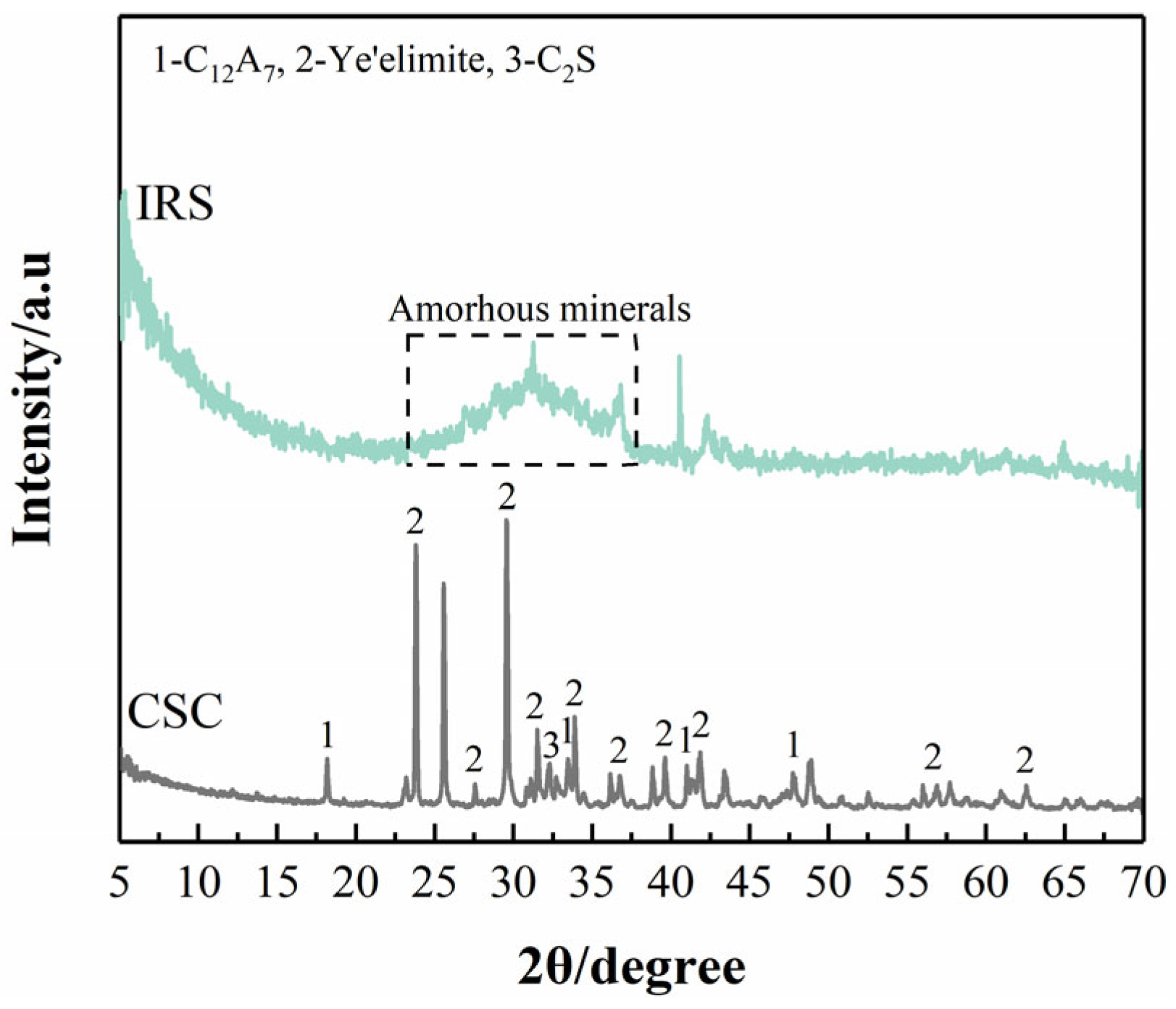
Figure 1. XRD patterns of CSC and IRS.
Buildings 15 03654 g001
Figure 2. Particle size distributions of IRS treated with different mechanical grinding time: (a) particle size distribution, (b) particle size passing, and (c) uniformity and size coefficient.
Buildings 15 03654 g002
Figure 3. FT-IR analysis of IRS treated with different mechanical grinding time.
Buildings 15 03654 g003
Figure 4. SEM/EDS analysis of IRS treated with different mechanical grinding time (a,d) for IRS0, (b,e) for IRS1, and (c,f) for IRS2.
Buildings 15 03654 g004
Figure 5. Compressive strength of mortar specimens containing IRS treated with different mechanical grinding time (a) 3 d, and (b) 28 d.
Buildings 15 03654 g005
Figure 6. Hydration heat of paste specimens containing IRS treated with different mechanical grinding time (a) heat flow (0–12 h), and (b) cumulative hydration heat (0–24 h).
Buildings 15 03654 g006
Figure 7. XRD analysis (a) 3 d, (b) 3 d (21–33°), (c) 28 d, and (d) 28 d (21–33°).
Buildings 15 03654 g007
Figure 8. TG/DTG analysis (a) DTG for 3 d, (b) TG for 3 d, (c) DTG for 28 d, (d) TG for 28 d, (e) quantitative results for 3 d, and (f) quantitative results for 28 d.
Buildings 15 03654 g008
Figure 9. SEM analysis at 3 d (a) Blank, (b) IRS0/30, (c) IRS1/30, (d) IRS2/30, (e) IRS2/40, and (f) IRS2/50.
Buildings 15 03654 g009
Figure 10. SEM analysis at 28 d (a) Blank, (b) IRS0/30, (c) IRS1/30, (d) IRS2/30, (e) IRS2/40, and (f) IRS2/50.
Buildings 15 03654 g010
Figure 11. SEM/EDS micrographs and elemental distribution maps of Blank.
Buildings 15 03654 g011
Figure 12. SEM/EDS micrographs and elemental distribution maps of IRS2/30.
Buildings 15 03654 g012
Figure 13. Atomic ratio of S/Ca vs. (Al + Fe)/Ca in IRS2/30.
Buildings 15 03654 g013
Figure 14. Pore size distributions of the blank and the IRS2/30 at 28 d.
Buildings 15 03654 g014
Table 1. Chemical compositions of CSC and IRS.
CaOAl2O3SO3SiO2Fe2O3MgOZnOK2OMnO
CSC/%56.0915.0216.784.514.031.130.020.320.05
IRS/%12.096.744.0920.3043.081.284.521.781.69
Table 2. Basic performance of CSC.
Fineness/m2·kg−1Setting Time/minCompressive Strength/MPa (w/b Raito = 0.42)Flexural Strength/MPa (w/b Raito = 0.42)
InitialFinal1 d3 d1 d3 d
40101537.245.16.16.5
Table 3. Mixture proportions.
Specimens IDCSC/gIRS0/gIRS1/gIRS2/gSand/gWater/g
Blank450///1350225
IRS0/2036090//1350225
IRS0/30315135//1350225
IRS0/40270180//1350225
IRS0/50225225//1350225
IRS1/20360/90/1350225
IRS1/30315/135/1350225
IRS1/40270/180/1350225
IRS1/50225/225/1350225
IRS2/20360//901350225
IRS2/30315//1351350225
IRS2/40270//1801350225
IRS2/50225//2251350225
Table 4. Elemental composition data obtained via SEM/EDS.
Specimens IDElements (%)
CaSiAlSFe
Blank66.153.3516.4013.920.00
IRS2/3052.245.9117.3715.928.55
Disclaimer/Publisher’s Note: The statements, opinions and data contained in all publications are solely those of the individual author(s) and contributor(s) and not of MDPI and/or the editor(s). MDPI and/or the editor(s) disclaim responsibility for any injury to people or property resulting from any ideas, methods, instructions or products referred to in the content.