Article

Vibration Control and Energy Harvesting of a Two-Degree-of- Freedom Nonlinear Energy Sink to Primary Structure Under Transient Excitation

School of Civil and Hydraulic Engineering, Chongqing University of Science and Technology, Chongqing 401331, China
*
Authors to whom correspondence should be addressed.
Buildings 2025, 15(19), 3561; https://doi.org/10.3390/buildings15193561
Submission received: 25 August 2025 / Revised: 19 September 2025 / Accepted: 29 September 2025 / Published: 2 October 2025

Abstract

Environmental vibrations may affect the functional use of engineering structures and even lead to disastrous consequences. Vibration suppression and energy harvesting based on Nonlinear Energy Sink (NES) and the piezoelectric effect have gained significant attention in recent years. The harvested electrical energy can supply power to the structural health monitoring sensor device. In this work, the electromechanical-coupled governing equations of the primary structure coupled with the series-connected 2-degree-of-freedom NES (2-DOF NES) integrated by a piezoelectric energy harvester are derived. The absorption and dissipation performances of the system under varying transient excitation intensities are investigated. Additionally, the targeted energy transfer mechanism between the primary structure and the two NESs oscillators is investigated using the wavelet analysis. The reduced slow flow of the dynamical system is explored through the complex-variable averaging method, and the primary factors for triggering the target energy transfer phenomenon are revealed. Furthermore, a comparison is made between the vibration suppression performance of the single-degree-of-freedom NES (S-DOF NES) system and the 2-DOF NES system as a function of external excitation velocity. The results indicate that the vibration suppression performance of the first-level NES (NES1) oscillator is first stimulated. As the external excitation intensity gradually increases, the vibration suppression performance of the second-level NES (NES2) oscillator is also triggered. The 1:1:1, high-frequency, and low-frequency transient resonance captures are observed between the primary structure and NES1 and NES2 oscillators over a wide frequency range. The 2-DOF NES demonstrates superior efficiency in suppressing vibrations of the primary structure and exhibits enhanced robustness to varying external excitation intensities. This provides a new strategy for structural vibration suppression and online power supply for health monitoring devices.

1. Introduction

Environmental vibrations may affect the functional use of structures and even lead to disastrous consequences. For instance, the breeze vibration of transmission conductors may induce fatigue breakage of conductors, damage to connection fittings, and even collapse of transmission towers. To mitigate these issues, the vibration absorber serves as a prevalent tool for vibration suppression for the primary structure. However, traditional linear vibration absorbers primarily operate within a limited frequency range centered around the primary structure’s natural frequency [1]. In recent years, nonlinear dynamic absorbers have been widely used for structural vibration suppression due to broadband vibration suppression performance [2]. On the other hand, structures in vibrating environments are often fitted with online monitoring sensors to monitor the vibration signals of the structure in real time. The piezoelectric effect can convert the environmental vibration energy into electrical energy to power the online monitoring sensors, reducing the use of chemical batteries in the sensors [3,4]. The study of combining nonlinear vibration absorbers with piezoelectric effects can not only achieve vibration suppression of the primary structure but also convert the vibration energy absorbed by the absorber into electrical energy to supply power for online monitoring sensors, ultimately promoting the development of integrated research on structural vibration suppression and online monitoring [5,6,7].
NES was introduced as a novel type of nonlinear dynamic vibration absorber by Vakakis and Gendelman [8,9] in 2001. An NES typically consists of cubic nonlinear stiffness, damping, and mass components. An NES is widely employed for vibration suppression in structures due to the advantages of targeted energy transfer [10], wideband vibration suppression [11], and strong robustness [12]. NESs have been widely used in fields such as aerospace [13,14], civil engineering [15,16], and vibration energy harvesting [17,18].
The phenomenon of targeted energy transfer was first identified and studied by Gendelman et al. [10,19]. They employed the method of numerical simulation to investigate a coupled model of a single-degree-of-freedom (S-DOF) primary structure with varying additional masses. Georgiades et al. [20] investigated the interaction between NES oscillator and a linear dispersive rod, employing an NES oscillator for the suppression of continuous structural vibrations. The methods of wavelet transforms, empirical mode decomposition, and Hilbert transforms were employed to process the transient response. These revealed the high effectiveness of the NES oscillator as a passive wideband energy absorber. Georgiadis et al. [21] discovered that the NES oscillator has the ability to absorb a significant portion of the input energy, thereby enhancing the vibration isolation performance of the primary structure under transient excitation. Chouvion [22] investigated the effect of the additional mass and cubic nonlinear stiffness of an NES oscillator on the vibration suppression efficiency for the primary structure using wavelet analysis. Qiu et al. [23] proposed a design criterion for optimizing NES oscillator, which not only predicts the optimal targeted energy transfer at the resonant frequency but also achieves the best performance over a range of frequencies. To enhance the application of a traditional NES oscillator over a wider ranging external forcing amplitude, Yang et al. [24] presented a time-varying NES oscillator that essentially provides nonlinear and time-varying inertia mass. The resonant frequency can be dynamically modulated by using the angular velocity to trigger controlled target energy transfer. The wavelet spectra show that the NES oscillator achieves fast vibration suppression of the primary structure mainly through 1:1, 1:2, and 1:3 resonance capture. Recently, Wang and Ding [25] investigated the performance of a bistable NES oscillator for the vibration suppression of a nonlinear oscillator using the analytical and numerical methods. The wavelet frequency spectra and energy dissipation efficiency revealed that this bistable NES oscillator performed better than the traditional one. Zhang et al. [26] explored the vibration suppression performance of an inertial NES on cantilever beams. The significant vibration suppression effects on the beam were observed under transient excitation. The tristable NES with time-varying potential barriers was proposed to enhance the vibration suppression effciency of the traditional one [27]. Song et al. [28] studied the approximate and numerical solutions of the NES with negative stiffness. The parameter analysis was conducted on its vibration suppression performance.
On the other hand, scholars have successfully combined nonlinear vibration theory with piezoelectric effects [29,30,31], giant magnetostrictive material [32], and electromagnetic effects [33], achieving dual objectives of vibration suppression and energy harvesting from the primary structure. Moreover, the harvested electrical energy can supply power to the structural health monitoring sensor device. Ahmadabadi and Khadem [34] were some of the first scholars to couple a piezoelectric vibration harvesting device to an NES oscillator for vibration suppression and harvesting from a simply supported beams. Subsequently, various forms of energy harvesters based on NES oscillators were proposed. Kremer and Liu [35] experimentally and theoretically investigated the performance of the vibration absorption and energy harvesting of an NES oscillator with an electromagnetic energy harvester under transient excitation. Their research results indicated that 1:1 resonance, targeted energy transfer phenomenon, and initial energy dependence were observed in this system [36]. Lin et al. [37] numerically and approximately investigated the output performance of a bistable NES-based piezoelectric system with combined damping. The results indicated that the introduction of damping nonlinearity can effectively improve the vibration suppression performance under large excitation. Li et al. [38] developed a novel piecewise linear NES oscillator for simultaneous vibration suppression and energy harvesting. The transient behaviors of the system were examined by time responses, wavelet transform spectra, and the frequency energy plots. Chen et al. [39] proposed a bistable NES oscillator coupled electromagnetic harvester that can achieve vibration suppression and energy harvesting by reducing the threshold required for targeted energy transfer. The energy dissipation rate was investigated with optimal stiffness under different transient excitations. The performance of the bistable NES coupled with an electromagnetic harvester under repeated impulses of varying amplitude was also analyzed [40]. Jin et al. [41] developed a non-traditional variant NES oscillator for vibration suppression and energy harvesting. The performance of this apparatus was investigated under transient excitation using numerical simulation. It revealed that this apparatus also exhibited characteristics such as initial energy dependence, 1:1 resonance, and targeted energy transfer. It showed better performance than the optimum non-traditional vibration absorber. Li et al. [42] investigated the transient response of an NES-based piezoelectric vibration energy harvesting system interfaced with a synchronized charge extraction interface. The initial input energy level and circuit parameters on the performance of the proposed system were explored. Xiong et al. [43] explored the influence of the electromechanical coupling of a piezoelectric device on the performance of nonlinear dynamic phenomena and output power under impulsive excitation. They revealed that the increase in electromechanical coupling ultimately leads to the failure of energy localization in NES and eventually affects the energy harvesting performance. Cai et al. [44] proposed a bistable energy-harvesting track NES for offshore wind turbines to simultaneously mitigate vibrations and harvest energy. Their results demonstrated that the device provides robust structural control and stable power output, outperforming a conventional energy-harvesting tuned mass damper under detuned conditions.
Compared to the S-DOF NES oscillator, the multi-degree-of-freedom NES absorber exhibits better robustness to system parameters, external excitation frequencies, and initial energy [45]. Du et al. [46] examined the vibration suppression performance of a multi-degree-of-freedom NES, and the results showed that the serial NES exhibited superior vibration suppression performance under large excitation. Zhang et al. [47] demonstrated that the target energy transfer efficiency and vibration suppression performance of the 2-DOF NES oscillators are superior to that of the S-DOF NES oscillator. Gendelman and Tsakirtzis et al. [48,49] explored the vibration suppression performance of the series-connected 2-DOF NES oscillators coupled to a primary structure. It revealed that compared to the S-DOF NES oscillator, the 2-DOF NES oscillators lowered the energy threshold and extended the range of the targeted energy transfer. The energy transfer of the system was mainly achieved through 1:1 transient resonance capture. The two NESs oscillators achieved an energy dissipation efficiency of up to 90% under specific initial conditions. Ahmadabadi and Khadem [50] presented an energy harvesting absorber that consists of the collocated two NESs oscillators and piezoelectric devices. The optimal vibration suppression and energy harvesting under transient excitation were examined. The results indicated that the energy dissipation performance was significantly superior to that of the S-DOF NES system. However, the targeted energy transfer efficiency and energy harvesting performance of the series-connected 2-DOF NES oscillators coupled with piezoelectric energy harvesting system under various initial transient excitations have not yet been clearly elucidated.
In this work, we explore the performance of vibration suppression and energy harvesting in a configuration consisting of series-connected 2-DOF NES oscillators coupled with a piezoelectric energy harvesting device, examining its response under varying transient excitation intensities. Our investigation is primarily focused on elucidating the mechanisms governing the initial energy transfer within the system, involving the primary structure, 2-DOF NES oscillators, and the piezoelectric device. The governing equations that describe the electromechanical coupling of this system are formulated in accordance with Newton’s second law and Kirchhoff’s voltage law. Subsequently, we investigate the impact of varying levels of external input energy on the vibration suppression and vibration energy harvesting capabilities of the system. To gain insights into the system’s behavior, we employ the complexification-averaging method to analyze the reduced slow flow. Additionally, we conduct a comparative analysis, examining the performance disparities between the S-DOF NES oscillator and the series-connected 2-DOF NES oscillators. The ultimate goal is to achieve the dual effects of structural vibration suppression and online monitoring sensor power supply.

2. Electromechanical-Coupled Dynamics Model

The primary structure coupled with the series-connected 2-DOF NES oscillators integrated with a piezoelectric energy harvester are depicted in Figure 1. The primary structure is modeled with the mass m 1 , linear stiffness k 1 , and linear damping coefficient c 1 . A typical NES generally consists of cubic stiffness, linear damping, and mass [8]. The first NES (NES1) oscillator, with a mass denoted as m 2 , is connected to the primary structure through the cubic nonlinear stiffness k 2 and a linear damping coefficient c 2 . The mass, cubic nonlinear stiffness, and linear damping coefficient of the second NES (NES2) oscillator are m 3 , k 3 , and c 3 , respectively. m 2 + m 3 m 1 . The external transient excitation satisfies the form of the Dirac function and is represented by P δ ( t ) . The piezoelectric device is embedded between the NES1 and NES2 oscillators. The piezoelectric device in Figure 1 is represented as an equivalent model, which consists of resistance R p , capacitance C p , electromechanical coupling coefficient θ , and equivalent linear stiffness k p . This method is commonly used to develop equivalent models of practical structures. Based on Newton’s second law and Kirchhoff’s voltage law, the system’s electromechanical-coupled governing equations can be obtained as follows:
m 1 x ¨ 1 + k 1 x 1 + k 2 ( x 1 x 2 ) 3 + c 1 x ˙ 1 + c 2 ( x ˙ 1 x ˙ 2 ) = P δ ( t ) , m 2 x ¨ 2 + k 2 ( x 2 x 1 ) 3 + k 3 ( x 2 x 1 ) 3 + c 2 ( x ˙ 2 x ˙ 1 ) + c 3 ( x ˙ 2 x ˙ 3 ) + k p ( x 2 x 3 ) θ u = 0 , m 3 x ¨ 3 + k 3 ( x 3 x 2 ) 3 + c 3 ( x ˙ 3 x ˙ 2 ) + k p ( x 3 x 2 ) + θ u = 0 , R p θ ( x ˙ 3 x ˙ 2 ) + R p C p u ˙ + u = 0 .
In the governing equations, u denotes the output voltage. x 1 , x 2 , and x 3 are the displacement responses of primary structure, NES1 oscillator and NES2 oscillator, respectively. For the convenience of derivation, the following variables are introduced:
ε 1 = m 2 m 1 , ε 2 = m 3 m 1 , α = k 1 m 1 , k n 1 = k 2 m 1 , k n 2 = k 3 m 1 , ζ 1 = c 1 m 1 , ζ 2 = c 2 m 1 , ζ 3 = c 3 m 1 , k p 1 = k p m 1 , θ p = θ m 1 , C p 1 = C p m 1 .
Substituting Equation (2) into Equation (1), the governing equations of the system can be written as
x ¨ 1 + α x 1 + k n 1 ( x 1 x 2 ) 3 + ζ 1 x ˙ 1 + ζ 2 ( x ˙ 1 x ˙ 2 ) = P δ ( t ) , ε 1 x ¨ 2 + k n 1 ( x 2 x 1 ) 3 + k n 2 ( x 2 x 1 ) 3 + ζ 2 ( x ˙ 2 x ˙ 1 ) + ζ 3 ( x ˙ 2 x ˙ 3 ) + k p 1 ( x 2 x 3 ) θ p u = 0 , ε 2 x ¨ 3 + k n 2 ( x 3 x 2 ) 3 + ζ 3 ( x ˙ 3 x ˙ 2 ) + k p 1 ( x 3 x 2 ) + θ p u = 0 , R p θ p ( x ˙ 3 x ˙ 2 ) + R p C p 1 u ˙ + u = 0 .
The transient excitation is represented as the initial velocity of the primary structure and is expressed as
x ˙ 1 ( 0 ) = η , x 1 ( 0 ) = x 2 ( 0 ) = x 3 ( 0 ) = x ˙ 2 ( 0 ) = x ˙ 3 ( 0 ) = 0 ,
where η represents the transient velocity suffered by the primary structure. The initial input energy of the system is defined as η 2 2 . The following formula is defined as
E d i s s 1 ( t ) = ζ 2 0 t [ x ˙ 1 ( τ ) x ˙ 2 ( τ ) ] 2 d τ η 2 / 2 × 100 % E d i s s 1 = lim t 1 E d i s s 1 ( t ) ,
E d i s s 2 ( t ) = ζ 3 0 t [ x ˙ 2 ( τ ) x ˙ 3 ( τ ) ] 2 d τ η 2 / 2 × 100 % E d i s s 2 = lim t 1 E d i s s 2 ( t ) ,
R 1 ( t ) = [ ε 1 x ˙ 2 ( t ) 2 + ( k n 1 / 2 ) [ x 2 ( t ) x 1 ( t ) ] 4 × 100 % ] / [ α x 1 2 ( t ) + x ˙ 1 ( t ) 2 + ε 1 x ˙ 2 ( t ) 2 + ( k n 1 / 2 ) [ x 2 ( t ) x 1 ( t ) ] 4 + ε 2 x ˙ 3 ( t ) 2 + ( k n 2 / 2 ) [ x 2 ( t ) x 3 ( t ) ] 4 ]
R 2 ( t ) = [ ε 2 x ˙ 3 ( t ) 2 + ( k n 2 / 2 ) [ x 2 ( t ) x 3 ( t ) ] 4 × 100 % ] / [ α x 1 2 ( t ) + x ˙ 1 ( t ) 2 + ε 1 x ˙ 2 ( t ) 2 + ( k n 1 / 2 ) [ x 2 ( t ) x 1 ( t ) ] 4 + ε 2 x ˙ 3 ( t ) 2 + ( k n 2 / 2 ) [ x 2 ( t ) x 3 ( t ) ] 4 ] ,
E h a r v e s t i n g ( t ) = 0 t [ u ( τ ) ] 2 d τ R p ,
where E d i s s 1 ( t ) and E d i s s 2 ( t ) represent the proportions of energy dissipated by the NES1 and NES2 oscillators to the input energy at different times t, respectively. The E d i s s 1 and E d i s s 2 , respectively, represent the proportion of energy dissipated by NES1 and NES2 oscillator to the input energy when the vibration response of the system stabilizes. The proportion of total energy dissipated by two NESs oscillators is E d i s s , and is expressed as E d i s s = E d i s s 1 + E d i s s 2 . R 1 ( t ) and R 2 ( t ) represent the proportions of transient energy stored in the two NESs oscillators at time t, respectively. The ratio of the total transient energy absorbed by the two NESs oscillators at time t is denoted as R ( t ) = R 1 ( t ) + R 2 ( t ) . E h a r v e s t i n g ( t ) represents the harvested power by the piezoelectric device from the NES2 oscillator at time t.

3. Approximation of the Reduced Slow Flow

To further investigate the cause of triggering the targeted energy transfer process, the complexification-averaging method is employed to analyze the reduced slow flow of the system. Complex variables are introduced as
ψ 1 = x ˙ 1 + j ω x 1 ; ψ 2 = x ˙ 2 + j ω x 2 ; ψ 3 = x ˙ 3 + j ω x 3 ; ψ 4 = u ˙ + j ω u ,
where j = 1 , ω is the circular frequency of the primary structure. The dot denotes the derivative with respect to time t. The displacements and accelerations of the primary structure and two NESs oscillators are rewritten in the form of complex variables
x ˙ 1 = 1 2 ( ψ 1 + ψ 1 ) , x ˙ 2 = 1 2 ( ψ 2 + ψ 2 ) , x ˙ 3 = 1 2 ( ψ 3 + ψ 3 ) ; x 4 = 1 2 ( ψ 4 + ψ 4 ) , x 1 = ψ 1 ψ 1 2 j , x 2 = ψ 2 ψ 2 2 j , x 3 = ψ 3 ψ 3 2 j ; x 4 = ψ 4 ψ 4 2 j , x ¨ 1 = ψ ˙ 1 1 2 j ( ψ 1 + ψ 1 ) , x ¨ 2 = ψ ˙ 2 1 2 j ( ψ 2 + ψ 2 ) , x ¨ 3 = ψ ˙ 3 1 2 j ( ψ 3 + ψ 3 ) , x 4 = ψ ˙ 4 1 2 j ( ψ 4 + ψ 4 ) .
Substituting Equations (10) and (11) into Equation (3) and then ignoring the influence of piezoelectric effect, the governing equation in the form of a complex variable can be written as
ψ ˙ 1 1 2 j ( ψ 1 + ψ 1 ) + α ( ψ 1 ψ 1 2 j ) + k n 1 ( ψ 1 ψ 1 2 j ψ 2 ψ 2 2 j ) + 1 2 ζ 1 ( ψ 1 + ψ 1 ) + 1 2 ζ 1 [ ( ψ 1 + ψ 1 ) ( ψ 2 + ψ 2 ) ] = 0 , ε 1 [ ψ ˙ 2 1 2 j ( ψ 2 + ψ 2 ) ] + k n 1 ( ψ 2 ψ 2 2 j ψ 1 ψ 1 2 j ) 3 + k n 2 ( ψ 2 ψ 2 2 j ψ 3 ψ 3 2 j ) 3 + 1 2 ζ 2 [ ( ψ 2 + ψ 2 ) ( ψ 1 + ψ 1 ) ] + 1 2 ζ 3 [ ( ψ 2 + ψ 2 ) ( ψ 3 + ψ 3 ) ] + k p 1 ( ψ 2 ψ 2 2 j ψ 3 ψ 3 2 j ) θ p ( ψ 4 ψ 4 2 j ) = 0 , ε 2 [ ψ ˙ 3 1 2 j ( ψ 3 + ψ 3 ) ] + k n 2 ( ψ 3 ψ 3 2 j ψ 2 ψ 2 2 j ) 3 + 1 2 ζ 3 [ ( ψ 3 + ψ 3 ) ( ψ 2 + ψ 2 ) ] + k p 1 ( ψ 3 ψ 3 2 j ψ 2 ψ 2 2 j ) + θ p ( ψ 4 ψ 4 2 j ) = 0 R p θ p [ 1 2 ( ψ 3 + ψ 3 ) 1 2 ( ψ 2 + ψ 2 ) ] + R p C p 1 1 2 ( ψ 4 + ψ 4 ) ) + ψ 4 ψ 4 2 j = 0 ,
where ∗ represents the conjugate complex. The previously introduced complex variables are approximately expressed in terms of the fast component e j t and modulated by slow varying amplitudes φ i , ( i = 1 , 2 , 3 , 4 ) , shown as
ψ 1 ( t ) = φ 1 e j t ; ψ 2 = φ 2 e j t ; ψ 3 = φ 3 e j t ; ψ 4 = φ 4 e j t .
Substituting Equation (13) into Equation (12), the governing equations are expressed as
φ 1 ˙ e j t + j φ 1 e j t 1 2 j ( φ 1 e j t + φ 1 e j t ) + α ( φ 1 e j t φ 1 e j t 2 j ) + k n 1 ( φ 1 e j t φ 1 e j t 2 j φ 2 e j t φ 2 e j t 2 j ) + 1 2 ζ 1 ( φ 1 e j t + φ 1 e j t ) + 1 2 ζ 2 [ ( φ 1 e j t + φ 1 e j t ) ( φ 2 e j t + φ 2 e j t ) ] = 0 , ε 1 [ φ 2 ˙ e j t + j φ 2 e j t 1 2 j ( φ 2 e j t + φ 2 e j t ) ] + k n 1 ( φ 2 e j t φ 2 e j t 2 j φ 1 e j t φ 1 e j t 2 j ) 3 + k n 2 ( φ 2 e j t φ 2 e j t 2 j φ 3 e j t φ 3 e j t 2 j ) 3 + 1 2 ζ 2 [ ( φ 2 e j t + φ 2 e j t ) ( φ 1 e j t + φ 1 e j t ) ] + 1 2 ζ 2 [ ( φ 2 e j t + φ 2 e j t ) ( φ 3 e j t + φ 3 e j t ) ] + k p 1 ( φ 2 e j t φ 2 e j t 2 j φ 3 e j t φ 3 e j t 2 j ) θ p ( φ 4 e j t φ 4 e j t 2 j ) = 0 , ε 2 [ φ 3 ˙ e j t + j φ 3 e j t 1 2 j ( φ 3 e j t + φ 3 e j t ) ] + k n 2 ( φ 3 e j t φ 3 e j t 2 j φ 2 e j t φ 2 e j t 2 j ) 3 + 1 2 ζ 3 [ ( φ 3 e j t + φ 3 e j t ) ( φ 2 e j t + φ 2 e j t ) ] + k p 1 ( φ 3 e j t φ 3 e j t 2 j φ 2 e j t φ 2 e j t 2 j ) + θ p ( φ 4 e j t φ 4 e j t 2 j ) = 0 , R p θ p [ 1 2 ( φ 3 e j t + φ 3 e j t ) 1 2 ( φ 2 e j t + φ 2 e j t ) ] + R p C p 1 1 2 ( φ 4 e j t + φ 4 e j t ) + φ 4 e j t φ 4 e j t 2 j = 0 .
Examining the slow variation component in Equation (14) and then averaging the fast variation component e j t , the influence of higher-order terms such as e 2 j t and e 3 j t are ignored. The slow varying amplitudes of governing equation are derived as
φ 1 ˙ + 1 2 j φ 1 1 2 j α φ 1 3 8 j k n 1 φ 1 φ 2 2 ( φ 1 φ 2 ) + 1 2 ζ 1 φ 1 + 1 2 ζ 2 ( φ 1 φ 2 ) = 0 , ε 1 ( φ 2 ˙ + 1 2 j φ 2 ) 3 8 j k n 1 φ 2 φ 1 2 ( φ 2 φ 1 ) 3 8 j k n 2 φ 2 φ 3 2 ( φ 2 φ 3 ) + 1 2 ζ 2 ( φ 2 φ 1 ) + 1 2 ζ 3 ( φ 2 φ 3 ) + k p 1 ( φ 2 2 j φ 3 2 j ) θ p φ 4 2 j = 0 , ε 2 ( φ 3 ˙ + 1 2 j φ 3 ) 3 8 j k n 2 φ 3 φ 2 2 ( φ 3 φ 2 ) + 1 2 ζ 3 ( φ 3 φ 2 ) + k p 1 ( φ 3 2 j φ 2 2 j ) + θ p φ 4 2 j = 0 R p θ p ( 1 2 φ 3 1 2 φ 2 ) + R p C p 1 1 2 φ 4 + φ 4 2 j = 0 .
In Equation (15), the φ i , ( i = 1 , 2 , 3 , 4 ) can be presented in the form of complex amplitudes. To obtain the approximate solution of the amplitudes, the polar form of the complex amplitudes is introduced
φ i ( t ) = ρ i ( t ) e θ i ( t ) , ( i = 1 , 2 , 3 , 4 ) ,
where ρ i ( t ) and θ i ( t ) denote the real amplitudes and phases. Substituting Equation (16) into Equation (15) and then separating the real and imaginary parts yield the following equation
ρ ˙ 1 + 3 8 k n 2 [ ρ 1 2 2 ρ 1 ρ 2 cos ( θ 1 θ 2 ) + ρ 2 2 ] ρ 2 sin ( θ 1 θ 2 ) + ζ 1 1 2 ρ 1 + 1 2 ζ 2 [ ρ 1 ρ 2 cos ( θ 1 θ 2 ) ] = 0 , ρ 1 j θ ˙ 1 + 1 2 j ρ 1 α j ρ 1 2 3 k n 1 j 8 ρ 1 3 3 8 k n 2 j [ ρ 1 2 2 ρ 1 ρ 2 cos ( θ 1 θ 2 ) + ρ 2 2 ] [ ρ 1 ρ 2 cos ( θ 1 θ 2 ) ] + 1 2 ζ 2 ρ 2 j sin ( θ 1 θ 2 ) = 0 , ε 2 ρ ˙ 2 3 8 k n 2 [ ρ 1 2 2 ρ 1 ρ 2 cos ( θ 1 θ 2 ) + ρ 2 2 ] ρ 1 sin ( θ 1 θ 2 ) + 3 8 k n 3 ( ρ 2 2 2 ρ 3 ρ 2 cos ( θ 2 θ 3 ) + ρ 3 2 ) ρ 3 sin ( θ 2 θ 3 ) + 1 2 ζ 2 [ ρ 2 ρ 1 cos ( θ 1 θ 2 ) ] + 1 2 ζ 3 [ ρ 2 ρ 3 cos ( θ 2 θ 3 ) ] + k p 1 2 ρ 3 sin ( θ 2 θ 3 ) θ p 2 ρ 4 sin ( θ 4 θ 2 ) = 0 , ε 2 ρ 2 θ ˙ 2 + ε 2 1 2 j ρ 2 3 8 k n 2 [ ρ 1 2 2 ρ 1 ρ 2 cos ( θ 1 θ 2 ) + ρ 2 2 ] [ ρ 2 ρ 1 cos ( θ 1 θ 2 ) ] 3 8 k n 3 ( ρ 2 2 2 ρ 3 ρ 2 cos ( θ 2 θ 3 ) + ρ 3 2 ) [ ρ 2 ρ 3 cos ( θ 2 θ 3 ) ] 1 2 ζ 2 ρ 1 sin ( θ 1 θ 2 ) + 1 2 ζ 3 ρ 3 sin ( θ 2 θ 3 ) k p 1 2 [ ρ 2 ρ 3 cos ( θ 2 θ 3 ) ] + θ p 2 [ ρ 4 cos ( θ 4 θ 2 ) ] = 0 , ε 3 ρ ˙ 3 3 8 k n 3 [ ρ 2 2 2 ρ 2 ρ 3 cos ( θ 2 θ 3 ) + ρ 3 2 ] ρ 2 sin ( θ 2 θ 3 ) + 1 2 ζ 3 [ ρ 3 ρ 2 cos ( θ 2 θ 3 ) ] k p 1 2 ρ 2 sin ( θ 2 θ 3 ) + θ p 2 ρ 4 sin ( θ 4 θ 3 ) = 0 , ε 3 ρ 3 θ ˙ 3 + ε 3 1 2 j ρ 3 3 8 k n 3 j [ ρ 2 2 2 ρ 2 ρ 3 cos ( θ 2 θ 3 ) + ρ 3 2 ] [ ρ 3 ρ 2 cos ( θ 2 θ 3 ) ] 1 2 ζ 3 ρ 2 sin ( θ 2 θ 3 ) k p 1 2 [ ρ 3 ρ 2 cos ( θ 2 θ 3 ) ] θ p 2 [ ρ 4 cos ( θ 4 θ 3 ) ] = 0 , 1 2 R p θ p [ ρ 3 cos ( θ 3 θ 4 ) ρ 2 cos ( θ 2 θ 4 ) ] + 1 2 R C p 1 ρ 4 = 0 , 1 2 R p θ p [ ρ 3 sin ( θ 3 θ 4 ) ρ 4 sin ( θ 2 θ 4 ) ] ρ 4 2 = 0 .

4. Results and Discussion

4.1. Analysis of Vibration Suppression and Energy Harvesting

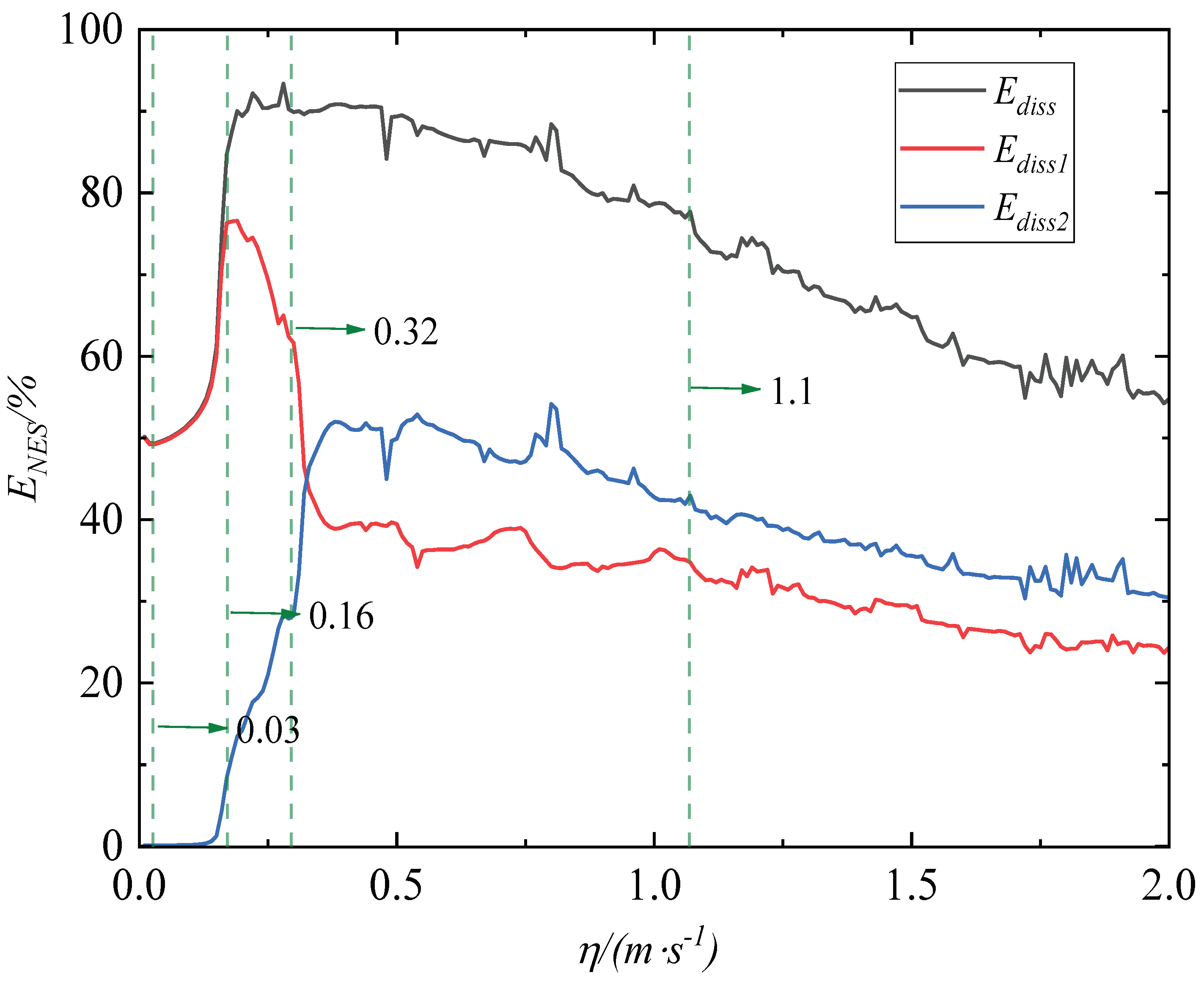
The parameters of the system are set as ε 1 = 0.09, ε 2 = 0.01, α = 1, k n 1 = 1, k n 2 = 0.008, ζ 1 = 0.01, ζ 2 = 0.01, ζ 3 = 0.002, R p = 8.2 × 10 5 , θ p = 8.0 × 10 7 , C p 1 = 1.0 × 10 8 , and k p = 2.1 × 10 8 . These parameters are not optimal but primarily intended to reflect the general principles of vibration control and vibration energy harvesting. The proportions of energy absorbed and dissipated by the two NESs oscillators for different initial velocities are calculated using the fourth-order Runge Kutta method, as shown in Figure 2.
As shown in the figure, the energy dissipation capacity of two NES oscillators is closely related to the input energy of the system. When the input energy of the system reaches a certain threshold, the energy dissipation performance of the NES1 oscillator is first triggered, and then the energy dissipation performance of the NES2 oscillator is triggered. Within the range of external excitation velocity less than 0.325 m/s, the NES1 oscillator shows better vibration suppression performance than the NES2 oscillator. Once the external excitation velocity exceeds 0.325 m/s, the NES2 oscillator exhibits better vibration suppression performance than the NES1 oscillator. The vibration suppression performance of two NES oscillators on the primary structure shows a trend of first increasing and then decreasing with the increase in the external excitation velocity.
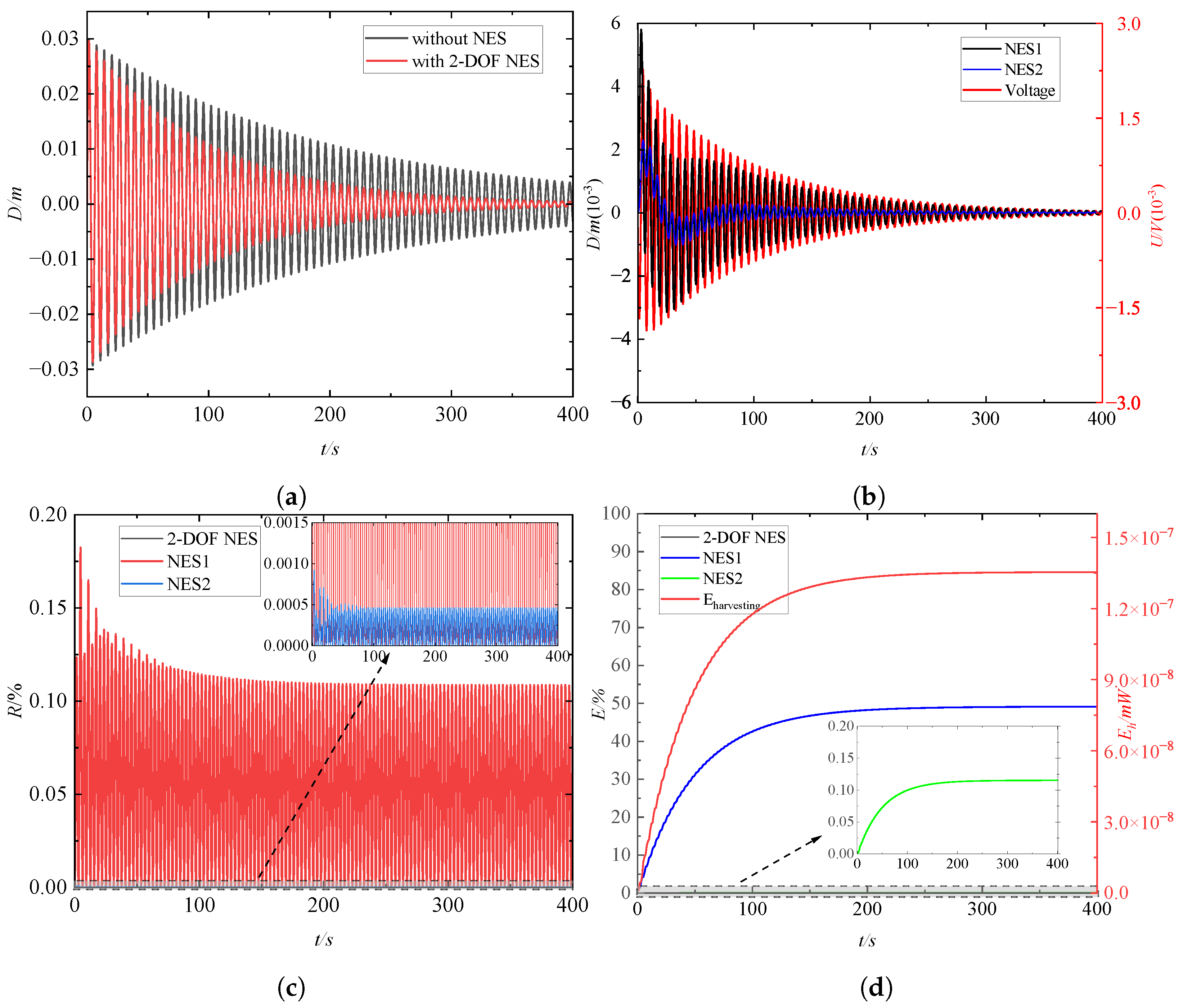
The effect of the initial velocity on the performance of the vibration suppression and energy harvesting of the two-NES–piezoelectric system is further discussed by selecting four different velocities, as shown in Figure 2. The four selected velocities are 0.03 m/s, 0.16 m/s, 0.32 m/s, and 1.1 m/s, respectively. The energy dissipation rates corresponding to two NES oscillators at the four excitation velocities mentioned above are 49.36%, 84.73%, 90.27%, and 77.67%, respectively. This behavior is common in such NES oscillators—their vibration suppression performance is relatively poor under both lower and higher excitation levels. There exists an optimal range of excitation intensity where they demonstrate superior vibration suppression performance. The dynamic time–history responses of the system at the velocity of η = 0.03 m/s are depicted in Figure 3.
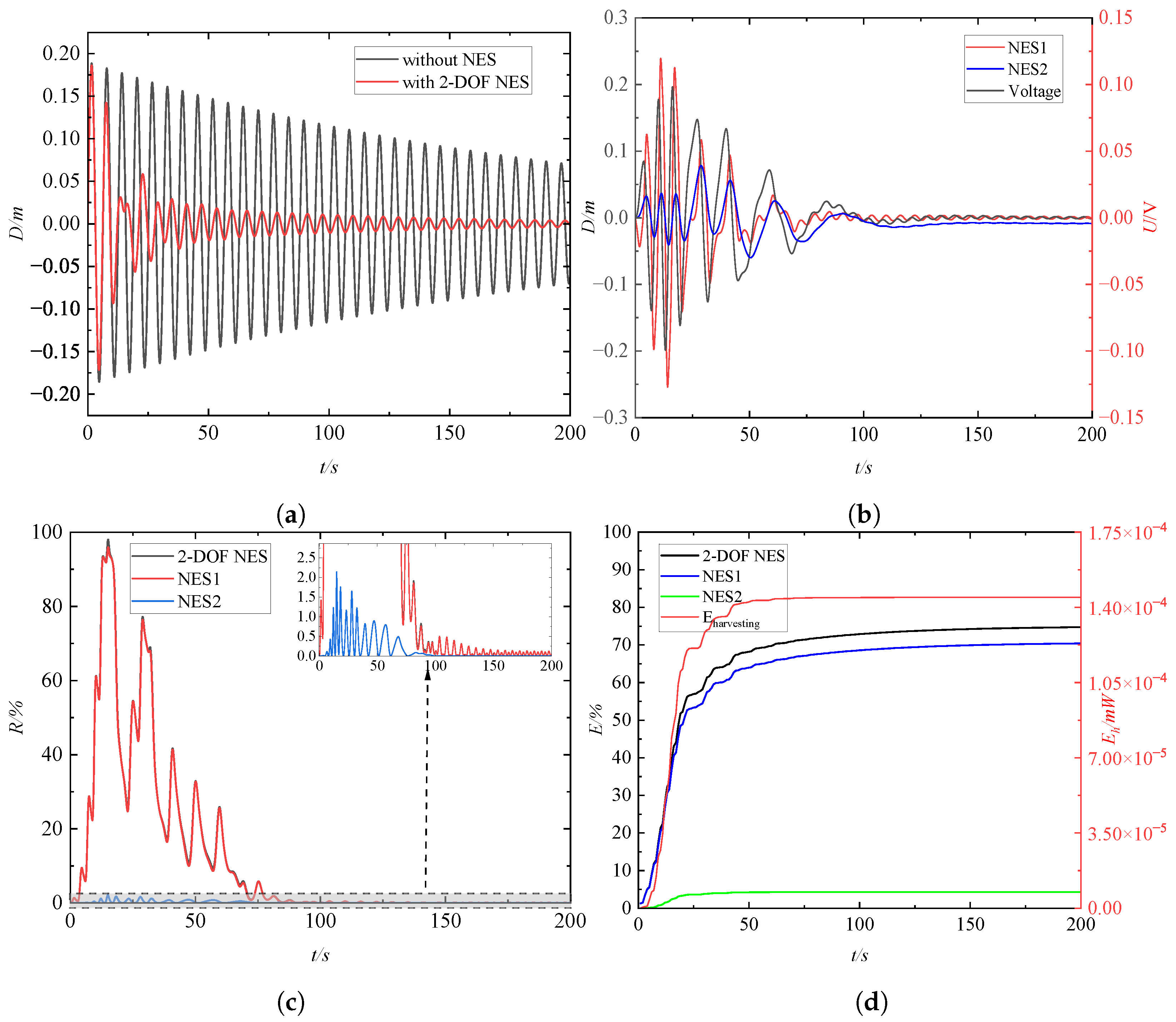
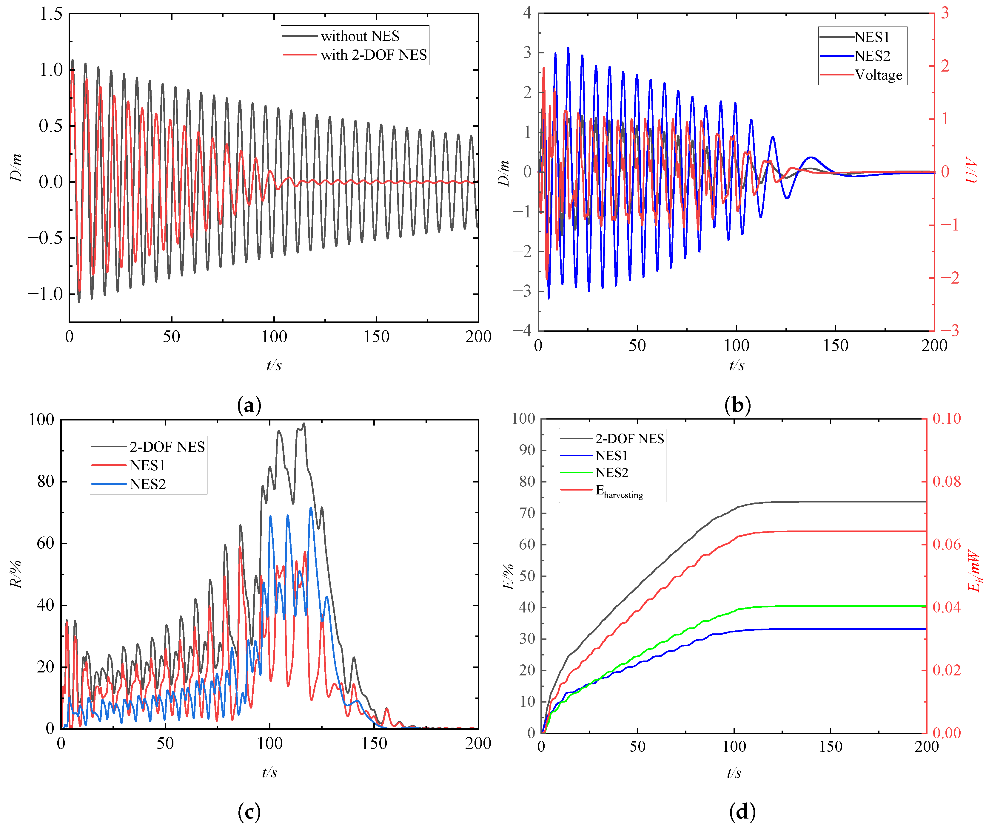
In Figure 3, Figure 4, Figure 5 and Figure 6, D denotes the displacement response of each level of the system, U denotes the voltage response of the piezoelectric device, and R denotes the instantaneous moment-to-moment energy share of each level, which is determined by Equations (7) and (8). E denotes the energy consumed by each level of the NES vibrator, and E h denotes the energy collected by the piezoelectric device.
At an excitation velocity of η = 0.03 m/s, Figure 3a,b indicate that the two-NES–piezoelectric device exhibits a certain degree of suppression on the primary structure’s amplitude. Notably, the amplitude of the primary structure significantly exceeds that of the NES1 and NES2 oscillators, and the voltage response harvested by the piezoelectric device can be essentially disregarded. Figure 3c highlights that the externally input energy primarily localizes within the primary structure, with transient energy within the two NES oscillators peaking at only around 0.18%. Furthermore, as depicted in Figure 3d, the system’s energy is primarily dissipated and absorbed by the primary structure, with only a minor portion being absorbed by the NES1 oscillator. On the other hand, the NES2 oscillator exhibit limited capacity for absorbing and dissipating external impact energy. Additionally, the piezoelectric energy harvesting system demonstrates minimal energy harvesting capabilities. These observations reveal that the vibration suppression and energy harvesting performance of the two-NES–piezoelectric device on the primary structure is not significant.
The excitation velocity was increased to η = 0.16 m/s, and the dynamic response of the system is illustrated in Figure 4. From Figure 4a,b, it can be observed that the two-NES–piezoelectric device exhibits a noticeable vibration suppression effect on the primary structure. The vibration displacement of the primary structure is significantly suppressed in a short period. In the initial phase, the amplitude of the NES1 oscillator is notably higher than that of the primary structure and NES2 oscillator. Figure 4c indicates that at t = 20 s, nearly 95% of the energy is transferred from the primary structure to the NES1 oscillator, with only a small portion of energy transmitted from the NES1 oscillator to the NES2 oscillator. In the subsequent period, energy is exchanged between the primary structure and the NES1 oscillator. The majority of the energy is unidirectionally transferred from the primary structure to the NES1 oscillator and stored therein. The NES2 oscillator is hardly involved in the vibration suppression of the primary structure. Figure 4d reveals that approximately 75% of the energy is absorbed and dissipated by the NES1 oscillator, while in contrast, the NES2 oscillator plays a minimal role in the dissipation of energy from the primary structure. Additionally, the piezoelectric device harvests only a small fraction of the energy.
The excitation velocity was increased to η = 0.32 m/s, and the system’s dynamic response is depicted in Figure 5. Figure 5a,b indicate a highly evident vibration suppression effect on the primary structure by the two-NES–piezoelectric device. The vibration displacement of the primary structure is significantly suppressed in the first 25 s, and the vibration displacement of the two NESs oscillators and the primary structure tends to stabilize after 75 s. In the first 20 s, the displacement of the NES1 oscillator is greater than that of the main structure and NES2 oscillator. After 20 s, the displacement of the NES2 oscillator significantly increases. Consequently, Figure 5 illustrates that at t = 6.7 s, nearly 70% of the energy has been transferred to the NES1 oscillator. In the range of 6.7 s to 25 s, although there is a brief energy oscillation transfer phenomenon between the primary structure and the NES1 oscillator, nearly 80% of the energy is ultimately targeted and transferred to the two NES oscillators. After 75 s, the energy transfer process between the primary structure and the two NES oscillators comes to a halt. Figure 5d shows that the energy dissipation efficiency of two NES oscillators under this condition approaches an optimal level, and the total energy of the two NES oscillators accounts for approximately 90% of the input energy from the primary structure. Compared to η = 0.16 m/s, the piezoelectric device harvests a greater amount of energy. The energy dissipation performance of the NES2 oscillator is notably enhanced, resulting in a significant overall improvement in the system’s energy harvesting capabilities.
The excitation velocity was increased to η = 1.1 m/s, and the dynamic response of the system is shown in Figure 6. Figure 6a,b reveal that in comparison to the case at an excitation velocity of η = 0.32 m/s, the two-NES–piezoelectric device requires a longer time for the vibration of the primary structure to stabilize. Additionally, the amplitude of the NES2 oscillator is significantly larger than that of NES1 and the primary structure. The voltage response harvested by the piezoelectric device also notably increases. As discerned in Figure 6c, a transient energy oscillation transfer occurs during the initial stage between the primary structure and the two NES oscillators. In the timeframe spanning approximately 90 s to 110 s, the targeted energy transfer phenomenon emerges between the two NES oscillators and the primary structure, ultimately localizing all energy within the two NES oscillators. It is evident that, in contrast to the excitation velocity of η = 0.32 m/s, the system necessitates a longer duration for targeted energy transfer, resulting in a relatively lower transfer efficiency. After 110 s, the energy transfer phenomenon concludes, with the two NES oscillators releasing a small amount of energy back to the primary structure. Since the energy transferred to the two NESsoscillators is predominantly dissipated by their damping, the energy returned to the primary structure can be considered negligible in comparison to the total input energy. Consequently, Figure 6d signifies that after 110 s, the energy absorbed and dissipated by the two NES oscillators stabilizes. The system’s energy dissipation primarily occurs within the two NES oscillators. The NES2 oscillator exhibits significantly superior energy dissipation performance than the NES1 oscillator within this dissipation process. Moreover, there is a substantial increase in the total energy harvested by the piezoelectric device.

4.2. Study of the Mechanism of Target Energy Transfer

The above analysis concluded that the efficiency of the targeted energy transfer determines the performance of vibration suppression and energy harvesting of the two-NES–piezoelectric device. The efficiency of targeted energy transfer depends on the initial input energy of the primary structure. In order to further investigate the intrinsic mechanism of targeted energy transfer, wavelet transform is used to conduct time–frequency analysis of the vibration displacement of primary structure and the two-NES–piezoelectric device at different initial velocities. The natural frequency of the primary structure is equal to 0.16 Hz.
Figure 7 shows the time–frequency response of the system’s vibration displacement at an initial excitation velocity of η = 0.03 m/s. As can be seen in Figure 3b and Figure 7b, the frequency components of the NES1 oscillator are consistent with the natural frequency of the primary structure, and the NES1 oscillator exhibits micro-amplitude vibration. This indicates that although there is a 1:1 transient resonance capture occurring between the primary structure and the NES1 oscillator, the role of nonlinear coupling between the primary structure and the NES1 oscillator is not obvious. Figure 7c shows that in addition to the frequency component that is the same as the natural frequency, there are also low-frequency components far from the natural frequency in the time–frequency response of the NES2 oscillator. Moreover, the contribution of these frequency components to the amplitude of the NSE2 oscillator is so insignificant that it can be almost ignored. Therefore, the vibrational displacement of the NES2 oscillator in Figure 3b is essentially negligible. This indicates that the coupling effect between the NES2 oscillator and the primary structure is not significant in this case, and the targeted energy transfer phenomenon between the NES1 and NES2 oscillators can be basically ignored.
The time–frequency response of the vibration displacement of the system is shown in Figure 8 when the initial excitation velocity is increased to η = 0.16 m/s. As can be seen in Figure 8b, the NES1 oscillator exhibits broadband phenomena around the natural frequency of the primary structure in the initial stage. Moreover, broadband phenomena also occur in the low-frequency range. The contribution of these frequency components to the vibrational displacements of the NES1 oscillator is also significantly larger. This suggests a stronger nonlinear coupling between the NES1 oscillator and the primary structure. The phenomenon of broadband transient resonance capture occurs near the natural frequency of the primary structure and in the low-frequency range. Figure 8c reveals that a similar broadband phenomenon to that of the NES1 oscillator also appears in the time–frequency spectrum of the NES2 oscillator. This indicates that a stronger nonlinear coupling between the NES2 and the NES1 oscillator also occurs. Part of the energy in the NES1 oscillator is transferred to the NES2 oscillator. Since the frequency component near the natural frequency of the primary structure is not obvious in Figure 8c, only part of the vibration suppression capability of the NES2 oscillator is excited. The corresponding energy dissipation performance of the NES2 oscillator is demonstrated in Figure 4d.
Figure 9 shows the time–frequency response of the system’s vibration displacement at an initial excitation velocity of η = 0.32 m/s. Compared with the initial excitation velocity η = 0.16 m/s, the significant broadband phenomenon near the natural frequency is observed. The significant high-frequency and low-frequency components are excited in the time–frequency spectra of both NES1 and NES2 oscillators in a short period of time. This indicates that strong nonlinear coupling between the primary structure and the NES1 oscillator, as well as between the NES1 and NES2 oscillators occurs. The 1:1:1 transient resonance capture phenomenon was observed between the primary structure and the NES1 and NES2 oscillators over a wide frequency range. The two NES oscillators and the primary structure quickly make synchronous motion with the same frequency, and the vibration energy of the primary structure flows unidirectionally into the two NES oscillators; then, the vibration suppression property of the two NES oscillators is excited.
Figure 10 shows the time–frequency response of the vibration displacement of the system at an initial excitation velocity of η = 1.1 m/s. Compared with the initial excitation velocity η = 0.32 m/s, the transient broadband resonance capture phenomenon between the primary structure and two NES oscillators disappears at this case. The transient resonance capture phenomenon of 1:1:1 only occurs near the natural frequency between the primary structure and two NES oscillators, resulting in a decrease in the efficiency of targeted energy transfer and vibration suppression.

4.3. Analysis of the Reduced Slow Flow

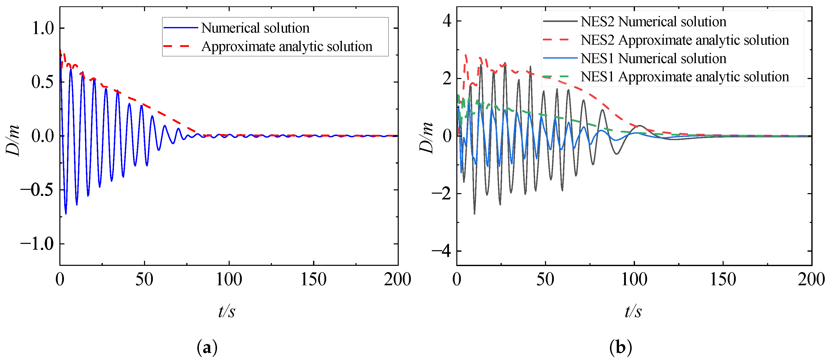
Before proceeding to the analysis of the reduced slow flow, we first verify the accuracy of the approximate analytical solution (Equation (17)). The initial conditions of the numerical solution are x 1 ( 0 ) = 0.8 , x 2 ( 0 ) = x 3 ( 0 ) = x ˙ 1 ( 0 ) = x ˙ 2 ( 0 ) = x ˙ 3 ( 0 ) = u ( 0 ) = 0 . The initial parameters of the approximate analytical solution are chosen as ρ 1 ( 0 ) = 0.8 ,   ρ 2 ( 0 ) = 0.0001 , ρ 3 ( 0 ) = 0.0001 , ρ 4 ( 0 ) = 0.0001 , ϕ 1 = 0 , and ϕ 2 = 0 . A comparison of the approximate and numerical solutions is shown in Figure 11.
As can be seen in Figure 11, the numerical solutions of the vibration displacements of the primary structure and NES1 are in good agreement with that of the approximate analytical solutions. Since the resonance capture mode between the primary structure and the NESs is accompanied by a certain amount of high-frequency and low-frequency resonance capture in addition to the 1:1:1 resonance capture at the initial stage, there is a certain amount of error between the numerical and approximate solutions. In general, the errors are small. Therefore, this approximate analytical solution can be used as a basis for the theoretical study of energy transfer within the system.
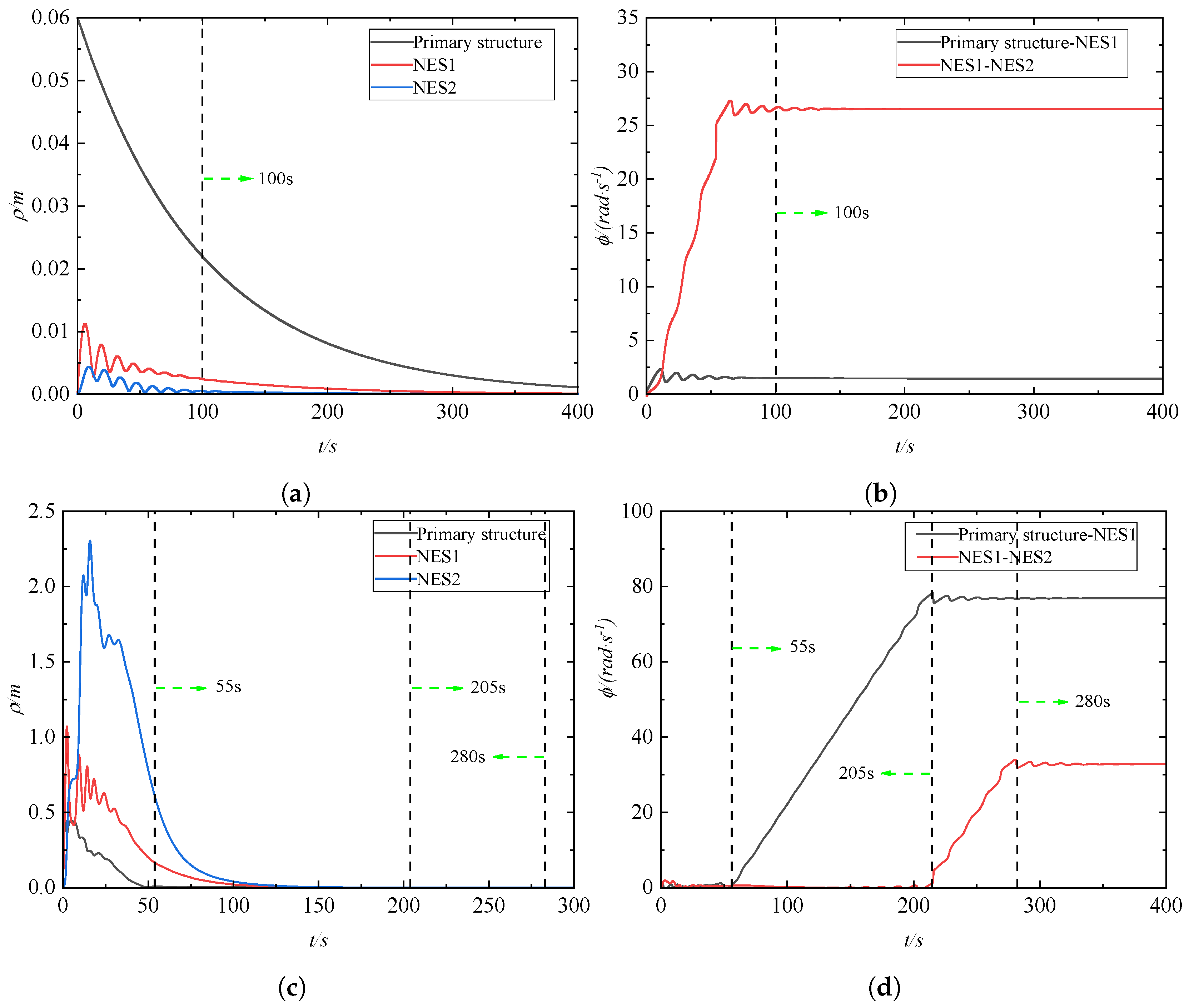
In the figure, ϕ 1 and ϕ 2 are the phase differences between the primary structure and NES1 oscillator and the NES1 and NES2 oscillators, respectively. They can be expressed as ϕ 1 = θ 1 θ 2 , ϕ 2 = θ 2 θ 3 . The variation curves of the slow-variable amplitude envelope and phase difference between the primary structure and the two NES oscillator with time for different initial displacements are depicted in Figure 12. The analysis parameters of the system are as follows: ρ 1 ( 0 ) = 0.06 , ρ 2 ( 0 ) = 0.0001 , ρ 3 ( 0 ) = 0.0001 , ρ 4 ( 0 ) = 0.0001 , ϕ 1 = 0 , ϕ 2 = 0 and ρ 1 ( 0 ) = 0.5 , ρ 2 ( 0 ) = 0.0001 , ρ 3 ( 0 ) = 0.0001 , ρ 4 ( 0 ) = 0.0001 , ϕ 1 = 0 , ϕ 2 = 0 .
Figure 12a,b indicate that when the initial input energy is small, the amplitudes of the two NES oscillators are much smaller than that of the primary structure, and the two NES oscillators show micro-amplitude vibration with time. The amplitude of the primary structure tends to stabilize around 400 s, and the phase difference between the primary structure and the two NES oscillators is always not equal to zero. Their phase difference tends to stabilize around 100 s. The coupling effect between the two NES oscillators and the primary structure is not significant, and it fails to stimulate the targeted energy transfer. As can be seen from Figure 12c,d, when the initial input energy increases, the amplitudes of the two NES oscillators increase sharply, and the amplitude of the primary structure decreases rapidly in the first 55 s. The phase difference between the primary structure and the two NES oscillators remains near the zero domain, resulting in the phase locking phenomenon. This indicates that a 1:1:1 transient resonance capture occurs between the primary structure and the NES1 and NES2 oscillators. The energy of the primary structure is efficiently transferred to the two NES oscillators, and the amplitude of the primary structure is effectively suppressed. In the range of 55 s to 205 s, since most of the energy of the primary structure is dissipated by the damping of two NES oscillators, the target energy transfer condition between the primary structure and the NES1 oscillator is destroyed. The motion state between the primary structure and the NES1 oscillator escapes from the 1:1 internal resonance state, while the 1:1 transient resonance capture state remains between the NES1 and NES2 oscillators. In the range of 205 s to 280 s, the energy between the NES1 and NES2 oscillators is not sufficient to satisfy the 1:1 internal resonance capture, and their motion states also escape from the 1:1 internal resonance state. The remaining energy of the system is already a very small fraction of the initial input energy.
In summary, it can be found that the initial impact energy is a key factor affecting the vibration suppression performance of two NES oscillators. Only when the initial energy reaches a certain threshold can the 1:1:1 transient resonance capture phenomenon between the primary structure and two NES oscillators quickly and efficiently absorb and dissipate the external impact energy, thereby enabling the primary system to stabilize quickly.

4.4. Comparison of the Performance Between the S-DOF NES System and the Series-Connected 2-DOF NES System

Relevant studies have demonstrated that the S-DOF NES oscillator provides better vibration suppression than conventional linear absorbers [51]. This section focuses on comparing the vibration suppression performance of series-connected 2-DOF NESs oscillators and an S-DOF NES oscillator for the primary structure under transient excitation. The governing equation of the primary structure coupled with an S-DOF NES oscillator is
u ¨ + α u + k ˜ n 1 ( u v ) 3 + ζ 1 u ˙ + ζ 2 ( u ˙ v ˙ ) = P δ ( t ) , ε 0 v ¨ + k ˜ n 1 ( v u ) 3 + ζ 2 ( v ˙ u ˙ ) = 0 ,
where the vibration displacements of the primary structure and NES oscillator are expressed as u and v, respectively. The proportions of energy absorbed and dissipated by the S-DOF NES oscillator to the input energy at different times t are expressed as
E = ζ 2 0 t [ u ˙ ( τ ) v ˙ ( τ ) ] 2 d τ η 2 / 2 × 100 . %
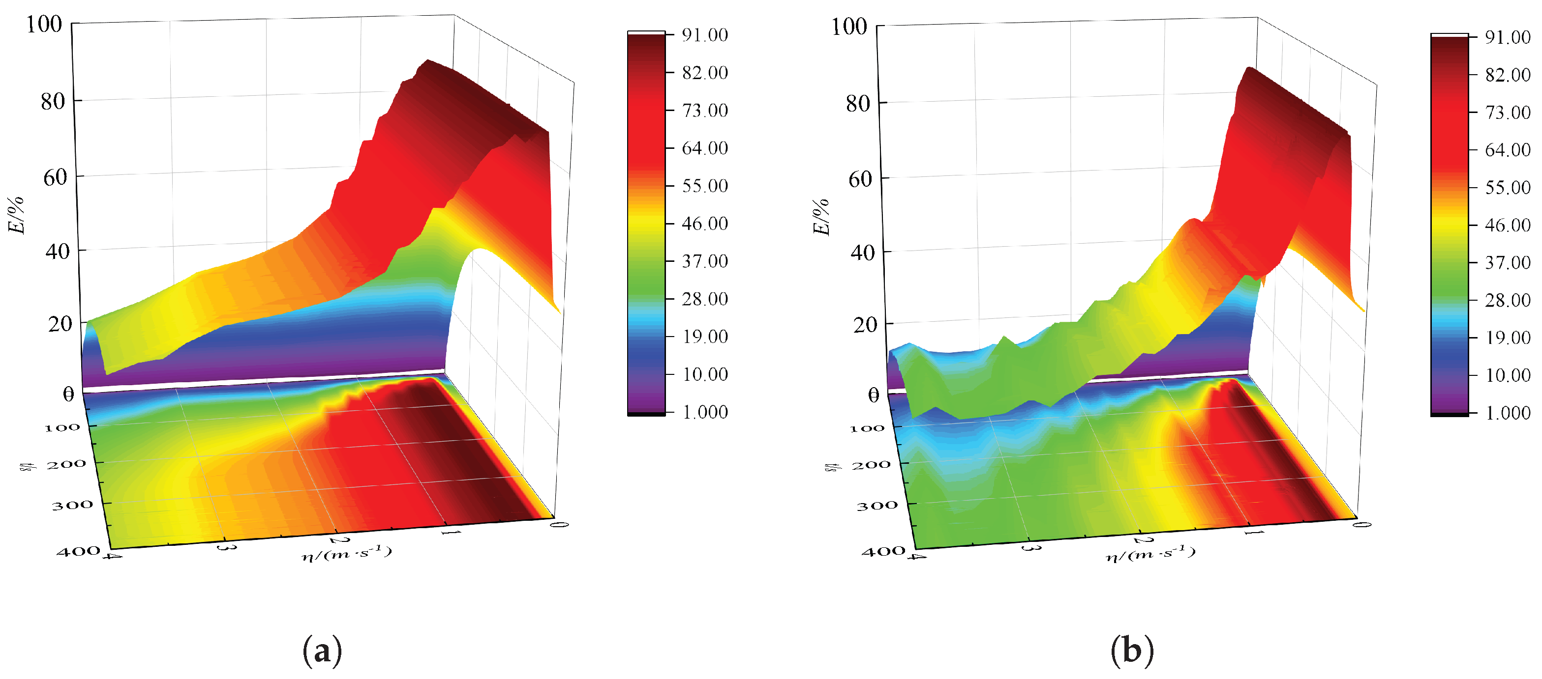
The analysis parameters of the system are as follows: ζ 1 = ζ 2 = 0.01 , k ˜ n 1 = 0.85 , ε 0 = 0.1 . Figure 13 shows the variation in the energy dissipation performance with different initial excitation velocities for the primary structure coupled with S-DOF NES and 2-DOF NES oscillators, where the mass, cubic stiffness, and damping parameters of the primary structure coupled with the S-DOF NES oscillator are selected to be the optimal ones after optimization [51]. The axes x, y, and z represent the external excitation velocity, time, and percentage of the energy dissipated by the NES oscillators.
Figure 13 reveals that both the S-DOF NES and 2-DOF NESs oscillators demonstrated excellent energy dissipation performance under small initial excitation, with a maximum energy dissipation rate of over 90%. As the external excitation velocity increases, the energy dissipation performance of the S-DOF NES oscillator significantly decreases, while the 2-DOF NESs oscillators still maintain a high energy dissipation rate. This is mainly due to the fact that the energy dissipation performance of the NES2 oscillator in the system of primary structure coupled with the 2-DOF NES oscillators is also excited, as the initial excitation exceeds a certain threshold. On the other hand, from the perspective of vibration suppression efficiency, when the initial excitation velocity is small, the energy dissipation capacity of both the S-DOF NES and 2-DOF NES oscillators can reach their maximum in a short period of time. As the external excitation velocity increases, the time required for the S-DOF NES oscillator to achieve maximum energy dissipation capacity becomes longer, while the 2-DOF NES oscillators can still achieve maximum energy dissipation performance in a short period of time. Therefore, compared with the vibration suppression performance of an S-DOF NES oscillator, the 2-DOF NES oscillators hold the advantages of robustness to the external excitation intensity and a high efficiency of energy dissipation.

5. Conclusions

On the one hand, an NES is a new type of nonlinear absorber with a wide bandwidth and high-efficiency vibration suppression performance. Compared with the conventional S-DOF NES, the series-connected 2-DOF NES demonstrates enhanced parametric robustness in the vibration suppression of primary structure. On the other hand, the piezoelectric effect can convert vibration energy in the environment into electrical energy, which can be used to provide electrical energy for structural health monitoring devices. The ultimate goal is to achieve the dual effects of structural vibration suppression and online monitoring sensor power supply. In this work, the electromechanically coupled governing equations for the primary structure coupled with a series-connected 2-DOF NES integrated with a piezoelectric energy harvester are derived using Newton’s second law and Kirchhoff’s voltage law. The performance of the vibration suppression and vibration energy harvesting of this coupled oscillator is explored under varying transient excitation intensities by numerical solution, wavelet transform, and the reduced slow flow method. The main conclusions are as follows:
(1)
When the transient excitation intensities are low, the vibration suppression primarily relies on 1:1 transient resonance capture and low-frequency transient resonance capture between the primary structure and the NES1 oscillator. However, as the transient excitation intensity surpasses a certain threshold, the vibration suppression of the structure by the NES oscillators is mainly achieved through 1:1:1 transient resonance capture, high-frequency transient resonance capture, and low-frequency transient resonance capture between the primary structure, the NES1 oscillator, and the NES2 oscillator over a wide frequency range. Under high transient excitation intensity, the vibration suppression of the NESs oscillator is predominantly achieved through the 1:1:1 transient resonance capture involving the primary structure, NES1 oscillator, and NES2 oscillator, albeit with a diminished level of performance.
(2)
The process of target energy transfer primarily arises from the strong nonlinear coupling between the primary structure and the two NESs oscillators. When the system enters the 1:1:1 transient resonance capture state, synchronous motion occurs between the primary structure and the two NESs oscillators, resulting in the phenomenon of target energy transfer. As the energy gradually dissipates, the strong nonlinear coupling diminishes, disrupting the targeted energy transfer condition and causing the system’s vibration state to deviate from the transient resonance capture state.
(3)
Compared with the vibration suppression performance of an S-DOF NES oscillator, the 2-DOF NES oscillators hold the advantages of enhanced robustness against external excitation intensity and efficiency of energy dissipation to the primary structure. The harvested energy can supply power to the structural health monitoring sensor device. In future work, a 2-DOF NES–piezoelectric system can be designed for a real-world structure, followed by further experimental studies on base excitation.

Author Contributions

Conceptualization, X.L. and X.N.; methodology, X.L. and X.N.; software, X.L.; validation, X.L., J.F. and Y.Q.; formal analysis, X.L. and J.F.; investigation, X.L., Y.Q., L.W. and Z.Y.; resources, X.L. and L.W.; data curation, X.L. and J.F.; writing—original draft preparation, X.L.; writing—review and editing, X.N. and L.W.; visualization, Y.Q.; supervision, X.N. and L.W.; project administration, X.N.; funding acquisition, X.N., L.W. and Z.Y. All authors have read and agreed to the published version of the manuscript.

Funding

This study was supported by the National Natural Science Foundation of China (Grant No.: 52178458), the Natural Science Foundation of Chongqing Science and Technology Commission (Grant No.: CSTB2022NSCQ-MSX0469), the Special Funding for Postdoctoral Research Projects of Chongqing (Grant No.: 2023CQBSHTB3009), and the Chongqing Graduate Research Innovation Project (Grant No.: CYS23749).

Data Availability Statement

The original contributions presented in the study are included in the article; further inquiries can be directed to the corresponding author.

Conflicts of Interest

The authors declare no conflicts of interest.

References

  1. Krenk, S.; Høgsberg, J. Tuned mass absorber on a flexible structure. J. Sound Vib. 2014, 333, 1577–1595. [Google Scholar] [CrossRef]
  2. Roberson, R.E. Synthesis of a nonlinear dynamic vibration absorber. J. Franklin Inst. 1952, 254, 205–220. [Google Scholar] [CrossRef]
  3. Wang, J.L.; Geng, L.F.; Ding, L.; Zhu, H.J.; Yurchenko, D. The state-of-the-art review on energy harvesting from flow-induced vibrations. Appl. Energy 2020, 267, 114902. [Google Scholar] [CrossRef]
  4. Jin, Y.; Xiao, S.; Zhang, Y. Enhancement of tristable energy harvesting using stochastic resonance. J. Stat. Mech. 2018, 267, 123211. [Google Scholar] [CrossRef]
  5. Nie, X.C.; Tan, T.; Yan, Z.M.; Yan, Z.T.; Zhang, W.M. Ultra-wideband piezoelectric energy harvester based on Stockbridge damper and its application in smart grid. Appl. Energy 2020, 267, 114898. [Google Scholar] [CrossRef]
  6. Yang, T.; Zhang, Y.Q.; Zhou, S.X. Multistage oscillators for ultra-low frequency vibration isolation and energy harvesting. Sci. China Technol. Sci. 2022, 65, 631–645. [Google Scholar] [CrossRef]
  7. Luo, H.; Liu, J.; Yang, T.; Zhang, Y.; Cao, Q. Dipteran flight-inspired bistable triboelectric nanogenerator for harvesting low frequency vibration. Nano Energy 2022, 103, 107755. [Google Scholar] [CrossRef]
  8. Vakakis, A.F. Inducing passive nonlinear energy sinks in vibrating systems. J. Vib. Acoust. 2001, 123, 324–332. [Google Scholar] [CrossRef]
  9. Gendelman, O.V.; Manevitch, L.I.; Vakakis, A.F. Energy pumping in nonlinear mechanical oscillators: Part I-Dynamics of the underlying Hamiltonian systems. J. Appl. Mech. 2001, 68, 34–41. [Google Scholar] [CrossRef]
  10. Gendelman, O.V. Transition of energy to a nonlinear localized mode in a highly asymmetric system of two oscillators. Nonlinear Dyn. 2001, 25, 237–253. [Google Scholar] [CrossRef]
  11. Qiu, D.H.; Seguy, S.; Paredes, M. Tuned nonlinear energy sink with conical spring: Design theory and sensitivity analysis. J. Mech. Design. 2018, 140, 011404. [Google Scholar] [CrossRef]
  12. Panagiotis, P.N.; Gendelman, O. Robustness of nonlinear targeted energy transfer in coupled oscillators to changes of initial conditions. Nonlinear Dyn. 2007, 47, 377–387. [Google Scholar]
  13. Lee, Y.S.; Vakakis, A.F.; Bergman, L.A.; McFarland, D.M.; Kerschen, G. Suppression aeroelastic instability using broadband passive targeted energy transfers, part 1: Theory. AIAA J. 2007, 45, 693–711. [Google Scholar] [CrossRef]
  14. Balaji, P.S.; SelvaKumar, K.K. Applications of nonlinearity in passive vibration control: A review. J. Vib. Eng. Technol. 2021, 9, 183–213. [Google Scholar] [CrossRef]
  15. Nucera, F.; Iocono, F.L.; McFarland, D.M. Application of broadband nonlinear targeted energy transfers for seismic mitigation of a shear frame: Experiment results. J. Sound Vib. 2008, 313, 57–76. [Google Scholar] [CrossRef]
  16. Wang, J.; Zheng, Y. Development and robustness investigation of track-based asymmetric nonlinear energy sink for impulsive response mitigation. Eng. Struct. 2023, 286, 116127. [Google Scholar] [CrossRef]
  17. Xiong, L.Y.; Tang, L.H.; Liu, K.F. Broadband piezoelectric vibration energy harvesting using a nonlinear energy sink. J. Phys. D Appl. Phys. 2018, 10, 1–19. [Google Scholar] [CrossRef]
  18. Yang, T.; Zhang, Y.; Zhou, S.; Fan, H.; Zhang, X. Wideband energy harvesting using nonlinear energy sink with bio-inspired hexagonal skeleton structure. Commun. Nonlinear Sci. 2022, 111, 106465. [Google Scholar] [CrossRef]
  19. Gendelman, O.V.; Gorlov, D.V.; Manevitch, L.I. Dynamics of coupled linear and essentially nonlinear oscillators with substantially different masses. J. Sound Vib. 2005, 286, 1–19. [Google Scholar] [CrossRef]
  20. Georgiades, F.; Vakakis, A.F.; Kerschen, G. Broadband passive targeted energy pumping from a linear dispersive rod to a lightweight essentially nonlinear end attachment. Int. J. Nonlinear Mech. 2007, 42, 773–788. [Google Scholar] [CrossRef]
  21. Georgiadis, F.; Vakakis, A.F. Shock isolation through passive energy pumping caused by nonsmooth nonlinearities. Int. J. Bifurcat. Chaos. 2005, 15, 1989–2001. [Google Scholar] [CrossRef]
  22. Chouvion, B. A wave approach to show the existence of detached resonant curves in the frequency response of a beam with an attached nonlinear energy sink. Mech. Res. Commun. 2019, 95, 16–22. [Google Scholar] [CrossRef]
  23. Qiu, D.; Seguy, S.; Paredes, M. Design criteria for optimally tuned vibro-transient nonlinear energy sink. J. Sound Vib. 2018, 442, 497–513. [Google Scholar] [CrossRef]
  24. Yang, T.; Hou, S.; Qin, Z.; Ding, Q.; Chen, L. A dynamic reconfigurable nonlinear energy sink. J. Sound Vib. 2021, 494, 115629. [Google Scholar] [CrossRef]
  25. Wang, T.; Ding, Q. Targeted energy transfer analysis of a nonlinear oscillator coupled with bistable nonlinear energy sink based on nonlinear normal modes. J. Sound Vib. 2023, 556, 117727. [Google Scholar] [CrossRef]
  26. Zhang, W.; Chang, Z.Y.; Chen, J. Vibration reduction for an asymmetric elastically supported beam coupled to an inertial nonlinear energy sink. J. Vib. Eng. Technol. 2023, 11, 1711–1723. [Google Scholar] [CrossRef]
  27. Zeng, Y.; Ding, H.; Ji, J.; Xiao, M.; Li, C. A tristable nonlinear energy sink with time-varying potential barriers. Commun. Nonlinear. Sci. 2025, 142, 108559. [Google Scholar] [CrossRef]
  28. Song, W.; Liu, Z.; Lu, C.; Li, B.; Zhu, D.; Nie, F. Analysis of vibration suppression performance of nonlinear energy sink with negative stiffness. J. Vib. Eng. Technol. 2022, 10, 1481–1493. [Google Scholar] [CrossRef]
  29. Tan, T.; Yan, Z.M.; Zou, Y.J.; Zhang, W. Optimal dual-functional design for a piezoelectric autoparametric vibration absorber. Mech. Syst. Signal Process. 2019, 123, 513–532. [Google Scholar] [CrossRef]
  30. Nie, X.C.; Tan, T.; Yan, Z.M.; Yan, Z.T.; Hajj, M.R. Broadband and high efficient L-shaped piezoelectric energy harvester based on internal resonance. Int. J. Mech. Sci. 2019, 159, 287–305. [Google Scholar] [CrossRef]
  31. Kremer, D.; Liu, K. A nonlinear energy sink with an energy harvester: Harmonically forced responses. J. Sound Vib. 2017, 410, 287–302. [Google Scholar] [CrossRef]
  32. Zhang, Y.W.; Gao, C.Q.; Zhang, Z.; Zang, J. Dynamic analysis of vibration reduction and energy harvesting using a composite cantilever beam with galfenol and a nonlinear energy sink. Int. J. Appl. Mech. 2021, 13, 2150089. [Google Scholar] [CrossRef]
  33. Hou, S.; Teng, Y.Y.; Zhang, Y.W.; Zang, J. Enhanced energy harvesting of a nonlinear energy sink by internal resonance. Int. J. Appl. Mech. 2019, 11, 1950100. [Google Scholar] [CrossRef]
  34. Ahmadabadi, Z.N.; Khadem, S.E. Nonlinear vibration control and energy harvesting of a beam using a nonlinear energy sink and a piezoelectric device. J. Sound Vib. 2014, 333, 4444–4457. [Google Scholar] [CrossRef]
  35. Kremer, D.; Liu, K. A nonlinear energy sink with an energy harvester: Transient responses. J. Sound Vib. 2014, 333, 4859–4880. [Google Scholar] [CrossRef]
  36. Zhang, Y.; Tang, L.; Liu, K. Piezoelectric energy harvesting with a nonlinear energy sink. J. Intell. Mat. Syst. Struct. 2017, 28, 307–322. [Google Scholar] [CrossRef]
  37. Lin, X.; Wang, L.; Wang, Z.; Yan, Z.; Qin, Y.; Nie, X. Vibration suppression and energy harvesting of nonlinear energy sink-based piezoelectric system with combined damping and bistability properties for nonlinear oscillator. Int. J. Struct. Stab. Dyn. 2024, 16, 2650017. [Google Scholar] [CrossRef]
  38. Li, X.; Liu, K.; Xiong, L.; Tang, L. Development and validation of a piecewise linear nonlinear energy sink for vibration suppression and energy harvesting. J. Sound Vib. 2021, 503, 116104. [Google Scholar] [CrossRef]
  39. Chen, L.; Liao, X.; Xia, G.; Sun, B.; Zhou, Y. Variable-potential bistable nonlinear energy sink for enhanced vibration suppression and energy harvesting. Int. J. Mech. Sci. 2023, 242, 107997. [Google Scholar] [CrossRef]
  40. Chiacchiari, S.; Romeo, F.; McFarland, D.M.; Bergman, L.A.; Vakakis, A.F. Vibration energy harvesting from impulsive excitations via a bistable nonlinear attachment. Int. J. Nonlinear Mech. 2017, 94, 84–97. [Google Scholar] [CrossRef]
  41. Jin, Y.; Liu, K.; Xiong, L.; Tang, L. A non-traditional variant nonlinear energy sink for vibration suppression and energy harvesting. Mech. Syst. Signal Process. 2022, 181, 109479. [Google Scholar] [CrossRef]
  42. Li, Z.; Tang, L.; Yang, W.; Zhao, R.; Liu, K.; Mace, B. Transient response of a nonlinear energy sink based piezoelectric vibration energy harvester coupled to a synchronized charge extraction interface. Nano Energy 2021, 87, 106179. [Google Scholar] [CrossRef]
  43. Xiong, L.; Tang, L.; Liu, K.; Mace, B.R. Effect of electromechanical coupling on dynamic characteristics of a piezoelectric nonlinear energy sink system. J. Vib. Eng. Technol. 2021, 9, 687–699. [Google Scholar] [CrossRef]
  44. Cai, Q.; Hua, Y.; Zhu, S.; Zhang, X.; Zuo, H. Bistable energy-harvesting track nonlinear energy sink in offshore wind turbines. Mech. Syst. Signal Process. 2024, 215, 111407. [Google Scholar] [CrossRef]
  45. Ding, H.; Chen, L.Q. Designs, analysis, and applications of nonlinear energy sinks. Nonlinear Dyn. 2020, 100, 3061–3107. [Google Scholar] [CrossRef]
  46. Du, T.; Ding, H.; Zhang, D. Series ness for suppressing strongly forced vibration. Int. J. Appl. Mech. 2024, 16, 2450030. [Google Scholar] [CrossRef]
  47. Zhang, Y.C.; Kong, X.R.; Tang, S.Y. Vibration suppression using targeted energy transfer in a two-degree-of-freedom unequal mass nonlinear vibration absorber. In Proceedings of the 61st International Astronautical Congress, Prague, Czech Republic, 27 September–1 October 2010; Volume 9, pp. 7373–7379. [Google Scholar]
  48. Gendelman, O.V.; Sapsis, T.; Vakakis, A.F.; Bergman, L.A. Enhanced passive targeted energy transfer in strongly nonlinear mechanical oscillators. J. Sound Vib. 2011, 330, 1–8. [Google Scholar] [CrossRef]
  49. Tsakirtzis, S.; Panagopoulos, P.N.; Kerschen, G.; Gendelman, O.; Vakakis, A.F.; Bergman, L.A. Complex dynamics and targeted energy transfer in linear oscillators coupled to multi-degree-of-freedom essentially nonlinear attachments. Nonlinear Dyn. 2007, 48, 285–318. [Google Scholar] [CrossRef]
  50. Ahmadabadi, Z.N.; Khadem, S.E. Optimal vibration control and energy scavenging using collocated nonlinear energy sinks and piezoelectric elements. In Proceedings of the ASME 2018 International Mechanical Engineering Congress and Exposition, Pittsburgh, PA, USA, 9–15 November 2018; p. 52040. [Google Scholar]
  51. Starosvetsky, Y.; Gendelman, O.V. Attractors of harmonically forced linear oscillator with attached nonlinear energy sink. II: Optimization of a nonlinear vibration absorber. Nonlinear Dyn. 2008, 51, 47–57. [Google Scholar] [CrossRef]
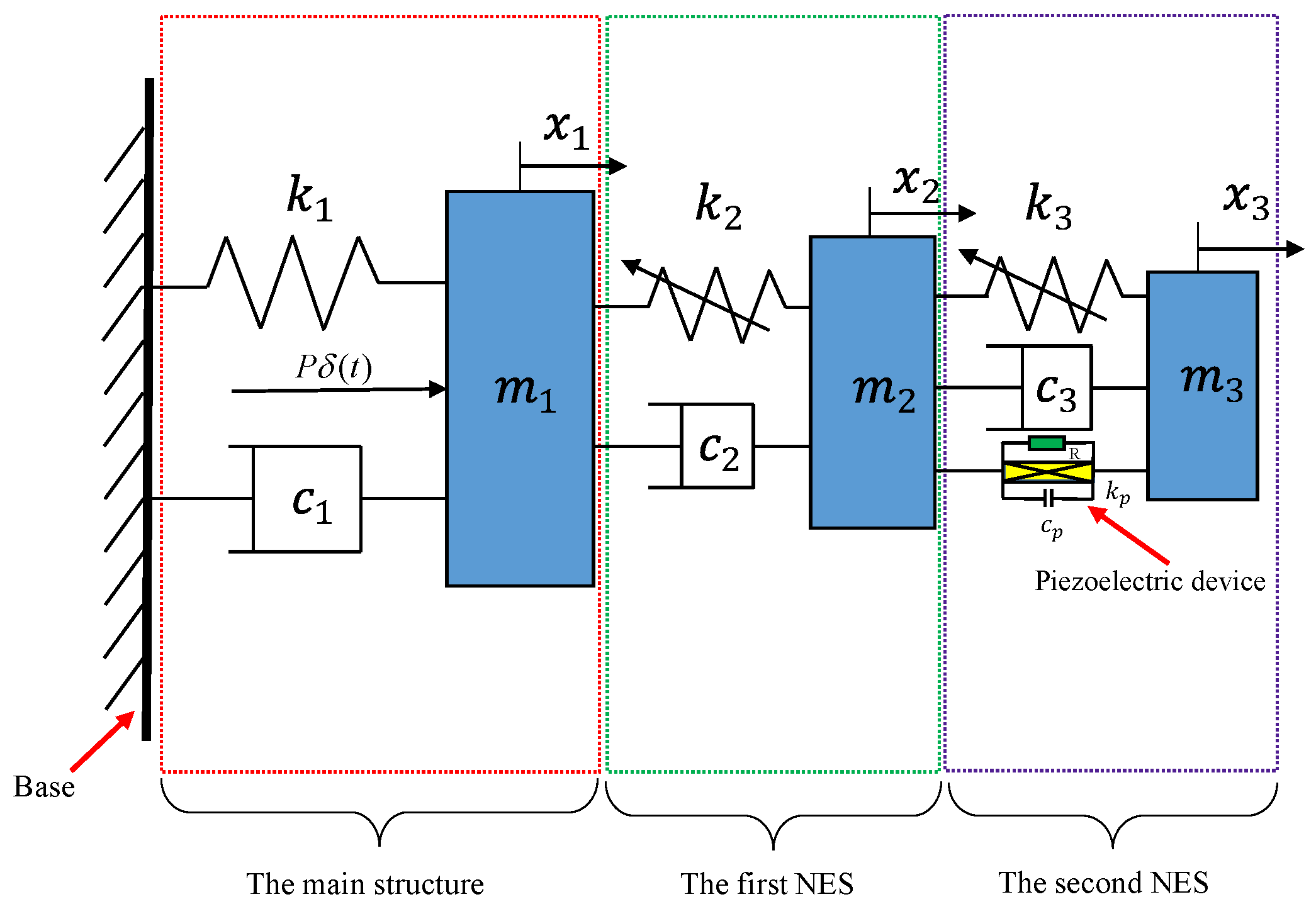
Figure 1. Schematic diagram of a series-connected 2-DOF NES coupled with a piezoelectric device system.
Buildings 15 03561 g001
Figure 2. The variation of energy absorbed and dissipated by two NES oscillators with initial velocity.
Buildings 15 03561 g002
Figure 3. The dynamic responses of the primary structure coupled with the two-NES–piezoelectric device system when the velocity of η = 0.03 m/s. (a) Displacement responses of the primary structure; (b) displacement and voltage responses; (c) transient energy stored by two NESs oscillators; (d) dissipated energy and haversted power.
Buildings 15 03561 g003
Figure 4. The dynamic responses of the primary structure coupled with the two-NES–piezoelectric device system when the velocity of η = 0.16 m/s. (a) Displacement responses of the primary structure; (b) displacement and voltage responses; (c) transient energy stored by two NESs oscillators; (d) dissipated energy and haversted power.
Buildings 15 03561 g004
Figure 5. The dynamic responses of the primary structure coupled with the two-NES–piezoelectric device system when the velocity of η = 0.32 m/s. (a) Displacement responses of the primary structure; (b) displacement and voltage responses; (c) transient energy stored by two NESs oscillators; (d) dissipated energy and haversted power.
Buildings 15 03561 g005
Figure 6. The dynamic responses of the primary structure coupled with the two-NES–piezoelectric device system when the velocity of η = 1.1 m/s. (a) Displacement responses of the primary structure; (b) displacement and voltage responses; (c) transient energy stored by two NESs oscillators; (d) dissipated energy and haversted power.
Buildings 15 03561 g006
Figure 7. The wavelet transform time–frequency spectrum of the system vibration displacement when the initial excitation velocity η = 0.03 m/s. (a) Primary structure; (b) NES1 oscillator; (c) NES2 oscillator.
Buildings 15 03561 g007
Figure 8. The wavelet transform time–frequency spectrum of the system vibration displacement when the initial excitation velocity η = 0.16 m/s. (a) Primary structure; (b) NES1 oscillator; (c) NES2 oscillator.
Buildings 15 03561 g008
Figure 9. The wavelet transform time–frequency spectrum of the system vibration displacement when the initial excitation velocity η = 0.32 m/s. (a) Primary structure; (b) NES1 oscillator; (c) NES2 oscillator.
Buildings 15 03561 g009
Figure 10. The wavelet transform time–frequency spectrum of the system vibration displacement when the initial excitation velocity η = 1.1 m/s. (a) Primary structure; (b) NES1 oscillator; (c) NES2 oscillator.
Buildings 15 03561 g010
Figure 11. Comparison between the numerical and approximate analytical solution. (a) Primary structure displacement response; (b) NES displacement response.
Buildings 15 03561 g011
Figure 12. Primary structure and NES oscillator response amplitude and phase difference. (a) ρ 1 ( 0 ) = 0.06 ; (b) ρ 1 ( 0 ) = 0.06 ; (c) ρ 1 ( 0 ) = 0.5 ; (d) ρ 1 ( 0 ) = 0.5 .
Buildings 15 03561 g012
Figure 13. Comparison of the performance between the S-DOF NES system and the series-connected 2-DOF NES system. (a) 2-DOF NES oscillators; (b) S-DOF NES oscillator.
Buildings 15 03561 g013
Disclaimer/Publisher’s Note: The statements, opinions and data contained in all publications are solely those of the individual author(s) and contributor(s) and not of MDPI and/or the editor(s). MDPI and/or the editor(s) disclaim responsibility for any injury to people or property resulting from any ideas, methods, instructions or products referred to in the content.