Article

Experimental Study on Bidirectional Bending Performance of Steel-Ribbed Composite Slabs for Electrical Substations

1
Shandong Electric Power Engineering Consulting Institute Co., Ltd., Jinan 250013, China
2
School of Civil Engineering, Shandong University, Jinan 250061, China
*
Author to whom correspondence should be addressed.
Buildings 2025, 15(19), 3540; https://doi.org/10.3390/buildings15193540
Submission received: 21 July 2025 / Revised: 9 September 2025 / Accepted: 29 September 2025 / Published: 1 October 2025
(This article belongs to the Section Building Structures)

Abstract

This study investigates the bidirectional bending performance of double- and triple-spliced steel-ribbed composite slabs for substation applications. Full-scale experiments and numerical parametric analyses were conducted to evaluate ultimate load, ductility, stiffness, failure modes, and load-transfer mechanisms. Results indicate that double-spliced slabs exhibit better performance than triple-spliced slabs, showing a 24.5% higher ultimate load and 65.3% greater ductility, with well-developed orthogonal cracks and yielding of both longitudinal prestressing steel and transverse reinforcement. Triple-spliced slabs display partial bidirectional behavior due to reduced transverse integrity, with stresses in edge slabs concentrated at the corners. Compared with monolithic slabs, spliced slabs show nearly identical stiffness at cracking onset but progressively reduced stiffness, load capacity, and ductility in the mid-to-late loading stages. Joint-crossing reinforcement is critical for transverse load transfer, and increasing its diameter is more effective than increasing its strength in preventing premature joint-controlled failure. These findings provide significant theoretical guidance and technical support for the prefabricated construction of high-voltage substation floor systems.

1. Introduction

With the deepening implementation of China’s “Dual Carbon” strategy, prefabricated construction has encountered rapid development opportunities in the field of power infrastructure [1,2,3]. As a critical node, electrical substations are transitioning toward a construction model characterized by “green and low-carbon, energy-saving and environmentally friendly, standardized design” [4,5,6]. Compared to civil buildings, substations endure harsher load conditions, particularly in floor slabs, which far exceed civil construction standards. Although traditional cast-in-place slabs feature mature techniques, they suffer from high resource consumption and low material utilization efficiency, making it difficult to meet the dual requirements of energy efficiency and construction speed in modern substation projects. Prefabricated composite slabs, which combine precast and cast-in-place techniques by pouring a layer of concrete over precast base slabs, have emerged as a key technological pathway for achieving green upgrades in substations. Their advantages, including factory production and efficient on-site assembly, make them an ideal solution.
In recent years, domestic and foreign scholars have engaged in extensive experimental studies and theoretical analyses concerning the mechanical properties of various composite slab types. Nie et al. [7] investigated the mechanical performance of precast slabs with steel lattice trusses, revealing that the truss reinforcement provides limited enhancement of bending stiffness. Zhou et al. [8] modified the composite slab by replacing the top truss chord with concrete-filled steel tubes and incorporating prestressing steel wires into the precast base slab. Key parameters, including anchorage methods, lapped reinforcement ratios, and overlay thickness of post-cast concrete, have been studied. Liu et al. [9] proposed a prestressed concrete composite slab featuring inverted T-shaped ribs and investigated the impact of rib configurations on bending performance. Hou et al. [10] further conducted twelve unidirectional bending tests to evaluate the influence of other parameters (e.g., concrete slab thickness, shear stud quantity, and longitudinal reinforcement ratio). Chen et al. [11] introduced a hollow concrete composite slab without protruding rebars on the slab side, and conducted bending performance tests on three tightly connected slabs and one seamless slab. Results indicate that tearing or brittle fracture failures are likely to occur at joint interfaces under ultimate conditions, leading to reduced flexural bearing capacity. Karimipanah et al. [12] performed experimental studies on the bending behavior of composite slabs with cold-formed profiled steel sheeting, demonstrating that the steel sheeting functions as tensile reinforcement alongside the concrete slab, with concrete crushing being the primary failure mode. Lu et al. [13,14,15] proposed a kind of prefabricated composite slab made from recycled aggregate concrete (RAC) and systematically investigated its flexural performance and longitudinal shear mechanism. A comprehensive design method incorporating bearing capacity, stiffness, and crack-width calculations were developed, contributing valuable guidance for sustainable design of composite slabs.
Regarding the bidirectional loading behavior of composite slabs and force transfer at joints, extensive studies have also been conducted. Stehle et al. [16] performed a series of tests on two-way spanning composite slabs with steel lattice trusses. Their findings confirm that sufficient supplementary reinforcement at the joints can effectively transfer bending moments and establish two-way load distribution mechanisms. Parallel research by Cheng et al. [17] involved stacking tests on four-edge supported, dense-spliced composite slabs with steel lattice trusses. These tests similarly verified that overlapping reinforcement at joints ensures dependable load transfer under bidirectional loading conditions, although minor discrepancies in crack patterns and stiffness characteristics were observed when compared with monolithic cast-in-place slabs. Wang et al. [18] further examined stress states at splicing joints, demonstrating that enhanced lap length and increased cross-sectional height at joints substantially improve structural integrity and flexural performance. Ciu et al. [19] systematically evaluated the influence of joint quantity, location, and cast-in-place layer thickness on the bidirectional bending behavior. Formulas for calculating bending stiffness reduction coefficients perpendicular to the joints were proposed. Chen et al. [20] improved the joint form by using grooves and closed-ring reinforcement, and Li et al. [21] proposed a new type of L-shaped joints. The structural performance of these new joint configurations demonstrates superior mechanical performance compared to conventional joints, yet imposes certain construction constraints. Shill et al. [22] compared the structural performances of two-way concrete slabs reinforced with conventional steel and FRP reinforcement, revealing that FRP-reinforced slabs exhibited greater crack propagation and deflection. Wang and Peng [23] introduced CFRP strip-reinforced dense-spliced joints, with experimental and numerical analyses confirming their enhanced stress transfer efficiency compared to traditional spliced systems.
The studies mentioned above primarily focused on the civil structures, with relatively limited exploration on prefabricated electrical substations. Lu et al. [24] addressed key design issues of precast concrete frame structures—including steel-truss composite slabs—in a 110 kV substation project, proposing relevant improvement measures. Liu et al. [25] implemented the prestressed steel-tube-truss composite slabs in an electrical substation, and quantitatively evaluated the influence of grouting strength, steel tube wall thickness, concrete strength, etc. Utilizing a 110 kV prefabricated substation project in Shenzhen as a case study, Li et al. [26] proposed technical measures covering prefabricated component production, assembly construction, and information management, along with recommendations to advance the adoption of prefabricated substations. Lei et al. [27] investigated the thermal–mechanical coupling evaluation of the panel performance of a prefabricated cabin-type substation based on machine learning. Li et al. [28] evaluated the performance of steel-ribbed composite slabs for a 500 kV substation project in China through numerical simulation, followed by a parametric analysis to identify the influence of key factors. The results indicate that the steel-ribbed composite slabs feature high cracking strength, post-crack stiffness, bearing capacity, and commendable ductility under both unidirectional and bidirectional loading conditions.
This study presents a new type of steel-ribbed composite slab based on the Daocheng (Huangbuling) 500 kV substation project in China. Full-scale experiments were carried out on double- and triple-spliced slabs to evaluate their bidirectional bending performance, with particular emphasis on failure modes, crack patterns, and load-transfer mechanisms at splicing joints. Subsequently, numerical parametric analyses were conducted to quantify the effects of key design variables. Based on these findings, conclusions and engineering implementation recommendations were given in the end.

2. Experimental Overview

2.1. Project Background

The Daocheng (Huangbuling) 500 kV substation, as illustrated in Figure 1a, represents Shandong Province’s first large-scale fully enclosed 500 kV substation. The substation was upgraded from an existing 220 kV facility. The evolution of the power grid structure and the introduction of new transformer equipment impose heightened structural requirements on substation floor slabs, with a design load of 34.2 kN/m2. In order to meet the stringent requirements, main and secondary beams are set beneath the floor slabs in high-load zones to provide edge support, as depicted in Figure 1b. The floor slabs enclosed by the main and secondary beams are subjected to typically bidirectional loading. The substation floor system employs steel-ribbed composite slabs, as shown in Figure 1c. The slabs offer higher stiffness, bearing capacity, and production efficiency compared with alternative slab systems. The composite slab consists of the precast base slab with inverted T-shaped ribs and post-cast concrete, with a total thickness of 130 mm after composition. The precast base slab measures 40 mm in thickness, with the inverted T-shaped ribs rising 70 mm in height. Each inverted T-shaped rib comprises a concrete upper flange and a Z-shaped steel web. The Z-shaped steel rib measures 67 mm in height and 1 mm in thickness, with its upper end anchored in a 150 mm × 40 mm concrete flange and lower end embedded in the precast base slab. Circular holes, 30 mm in diameter and spaced at 200 mm intervals, are perforated in the middle along the ribs to facilitate transverse reinforcement and utility routing. Longitudinal reinforcement in the precast base slab employs 1570-grade stress-relieved spiral-rib steel wires to enhance load-bearing capacity.

2.2. Specimen Design of Steel-Ribbed Composite Slabs

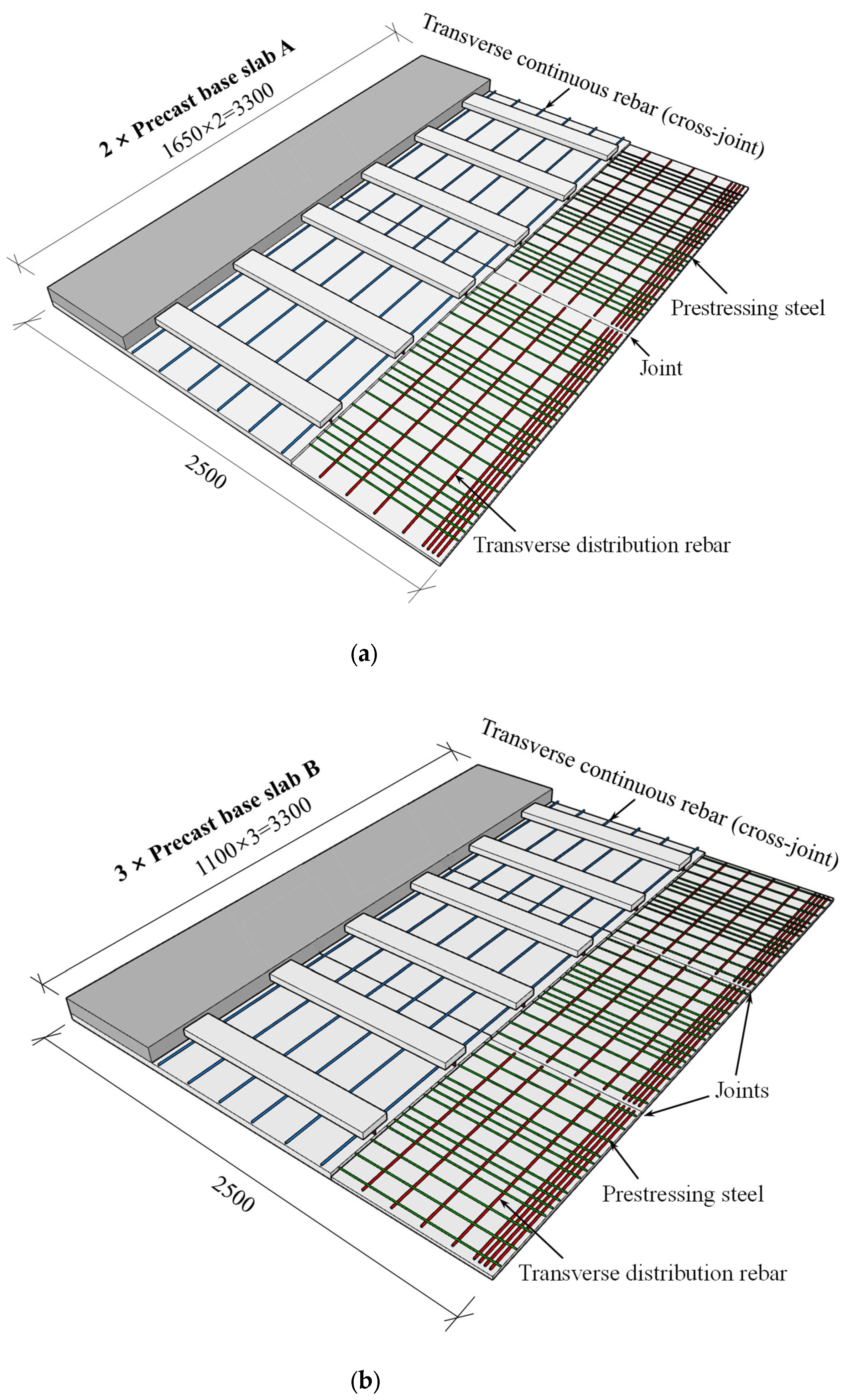
To investigate the bidirectional bending performance of the slabs after dense splicing, two test specimens, i.e., double-spliced and triple-spliced configurations, were designed based on the room dimensions, as shown in Figure 2. Both specimens shared identical overall dimensions of 3300 mm × 2500 mm × 130 mm. The double-spliced slab was assembled transversely by two precast base slabs (Type A) with a splicing joint at mid-width, while the triple-spliced slab comprised three precast slabs (Type B) with joints located at the one-third points. Transverse continuous rebars of C8@200 mm with a total length of (3300 + 120 × 2) mm were threaded through holes in Z-shaped steel ribs, providing additional reinforcement and enhancing transverse load transfer across the splicing joints.
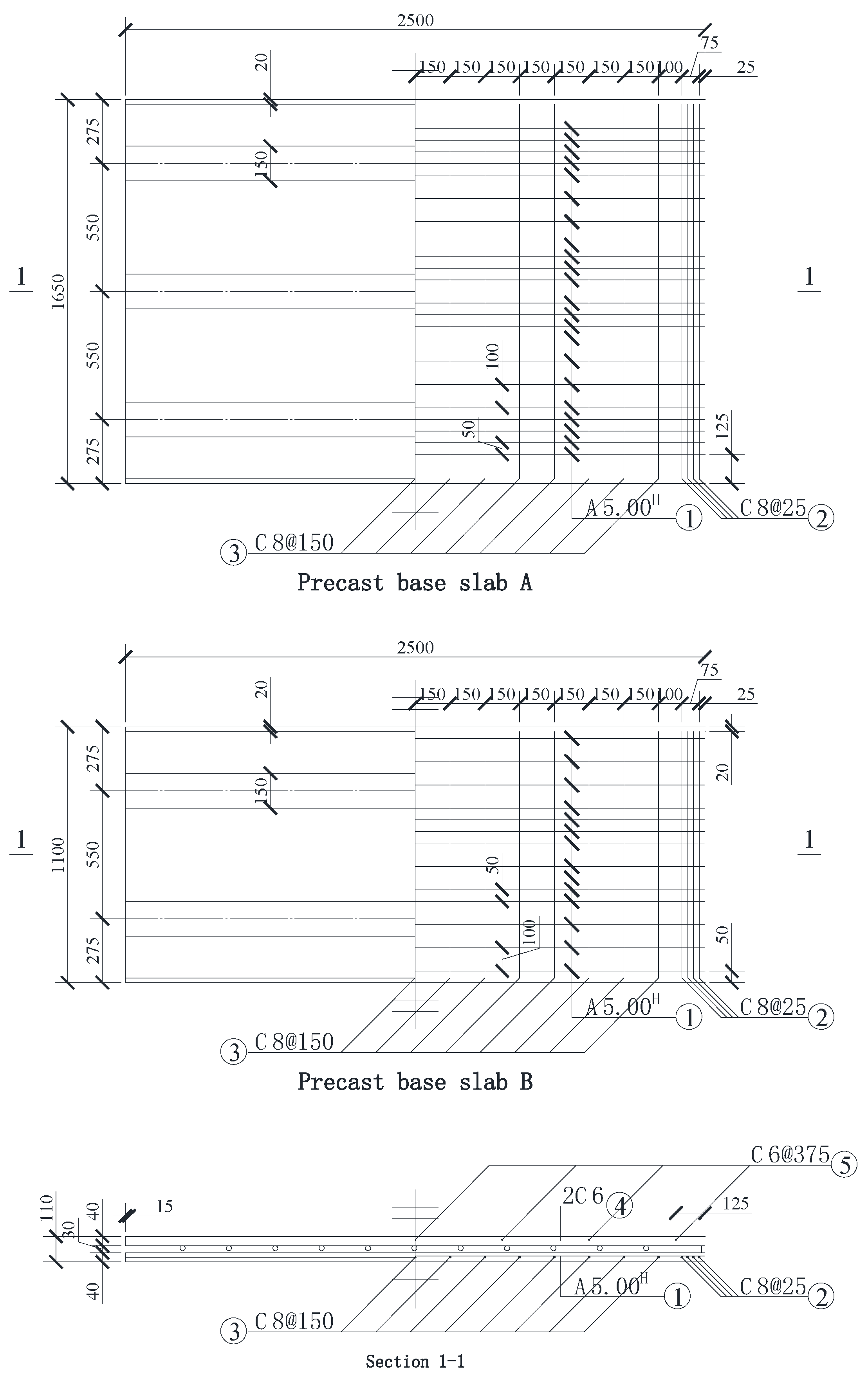
The detailed dimensions and reinforcement detailing of precast base slabs A and B are illustrated in Figure 3. Precast base slab A measures 1650 mm × 2500 mm and contains three T-shaped ribs, while precast base slab B measures 1100 mm × 2500 mm with two inverted T-shaped ribs. The center-to-center spacing between adjacent inverted T-shaped ribs is uniformly 550 mm in both slabs. Both the precast base slab and the post-cast concrete layer utilize C40 concrete. Prestressing steel (labeled as ① in Figure 3), composed of A5H 1570-grade stress-relieved spiral ribbed steel, is placed longitudinally in the precast slab, aligned with the direction of the steel ribs. The tension control stress of the prestressing steel is 1100 MPa, about 75% of the ultimate strength. Precast base slab A contains 22 prestressing steel wires (reinforcement ratio 0.201%), while slab B contains 14 wires (reinforcement ratio 0.192%). Transverse distribution rebars of diameter C8, spaced at 150 mm (labeled as ③ in Figure 3), are oriented perpendicular to the direction of prestressing. At the ends of the slab, the arrangement of the transverse distribution rebars is intensified, labeled as ② in Figure 3. Longitudinal steel rebars of 2C6 (labeled as ④ in Figure 3) and transverse steel rebars of C6 spaced at 375 mm (labeled as ⑤ in Figure 3) are placed in the concrete flange of steel ribs. The slanted cut at the edge of the precast base slab, aligned with the direction of the parallel prestressing steel, measures 20 mm × 20 mm.
To replicate the actual boundary conditions of the steel-ribbed bidirectional composite slab for substations, edge beams along the slab periphery were cast monolithically with the cast-in-place concrete topping, as depicted in Figure 4. The edge beams have a cross-section of 250 mm × 300 mm, reinforced with top/bottom flexural bars (3C16 & 4C20, labeled as ⑨ and ⑩), and C8 closed stirrups at 200 mm spacing (labeled as ⑫). To enhance the connectivity between the slab and the edge beams, transverse joint-crossing rebars (labeled as ⑥) extend 120 mm into the edge beams. Supplementary local rebars of C8 at 200 mm spacing (labeled as ⑪) are placed in the edge beams perpendicular to the prestressing steel, following the same configuration. Simultaneously, C8 connectors at 200 mm spacing (labeled as ⑦ and ⑧) are arranged on the top the inverted T-shaped ribs, with their ends anchored into the edge beams and mechanically bent.
The material parameters for steel and concrete components in the specimens are shown in Table 1.

2.3. Specimen Fabrication

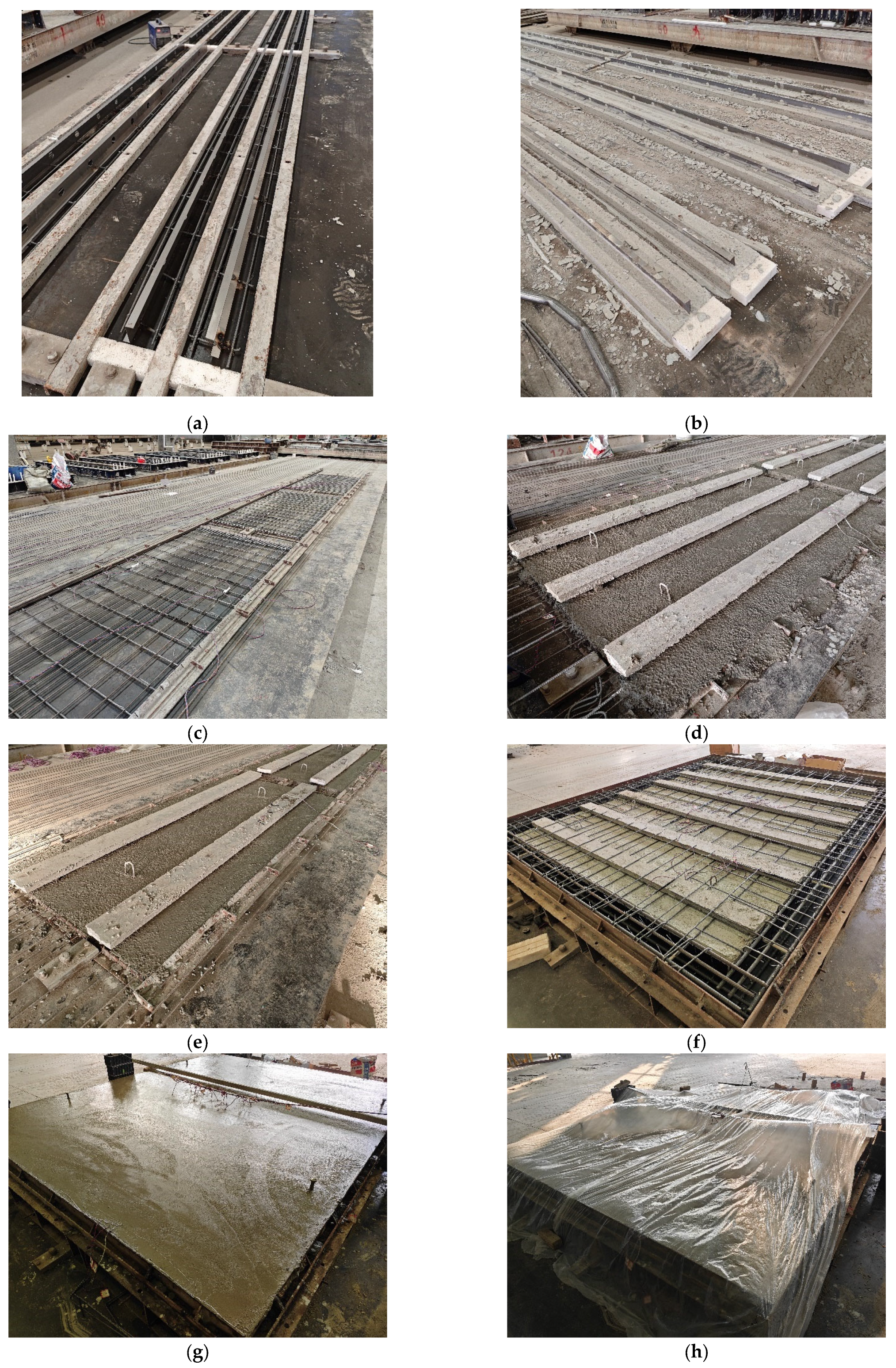
The fabrication process of the specimens is illustrated in Figure 5, and primarily includes the construction of inverted T-shaped ribs, fabrication of precast base slabs, casting of the composite overlay and edge beams, and curing of specimens.

2.4. Loading Apparatus and Instrumentation Layout

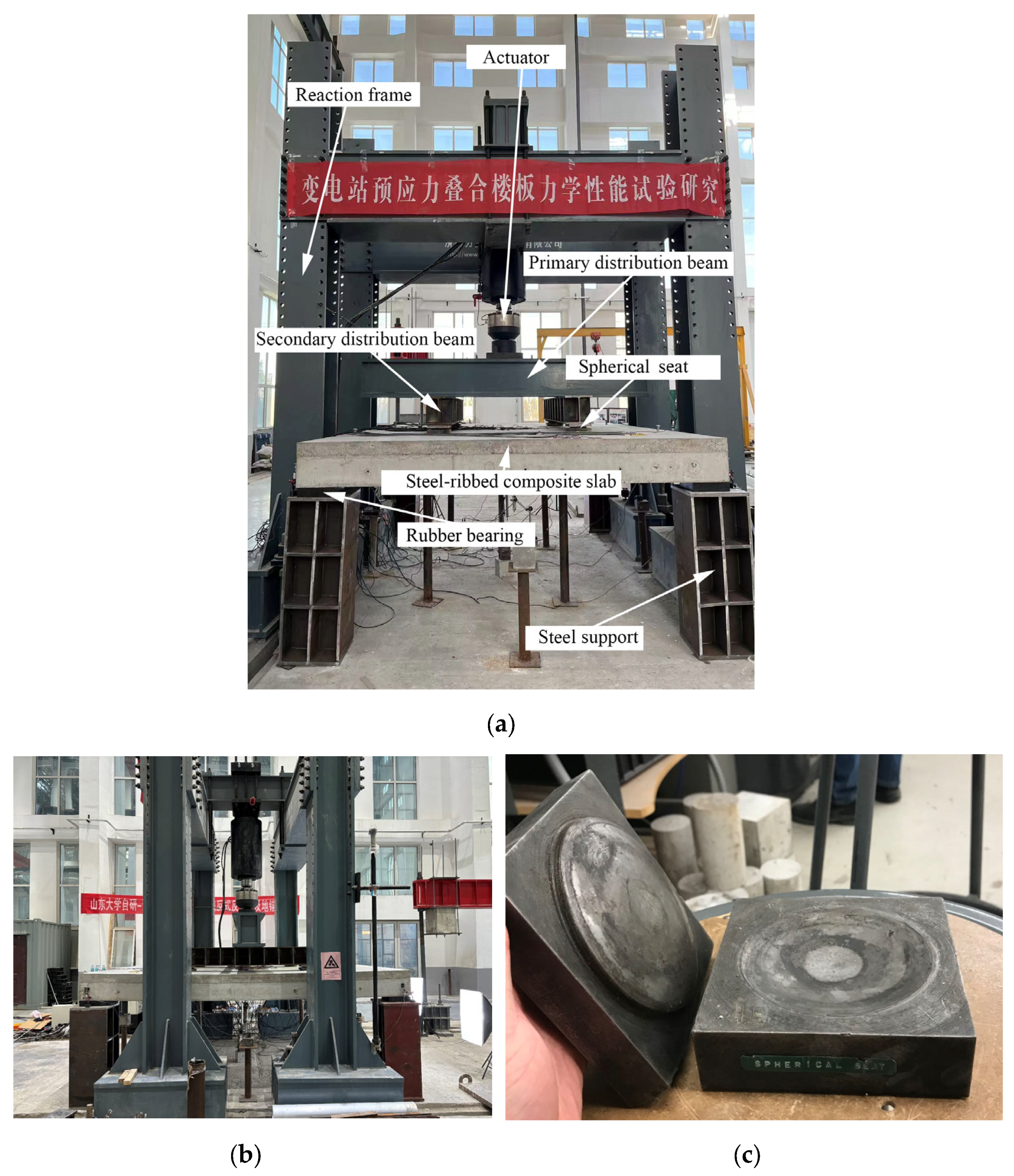
The front and side views of the loading system for the steel-ribbed composite bidirectional slab are shown in Figure 6a and Figure 6b, respectively. A 2000 kN reaction frame was employed for loading, with edge beam corners supported on steel piers via elastomeric bearings. The actuator applies vertical loads at four points through primary and secondary distribution beams. Spherical-hinge loading seats, as depicted in Figure 6c, are installed between the secondary distribution beams and the slab surface. During the initial and intermediate loading phases, load was applied at a rate of 5 kN/min. Prior to failure, the test switches to displacement-controlled loading at 0.5 mm/min.
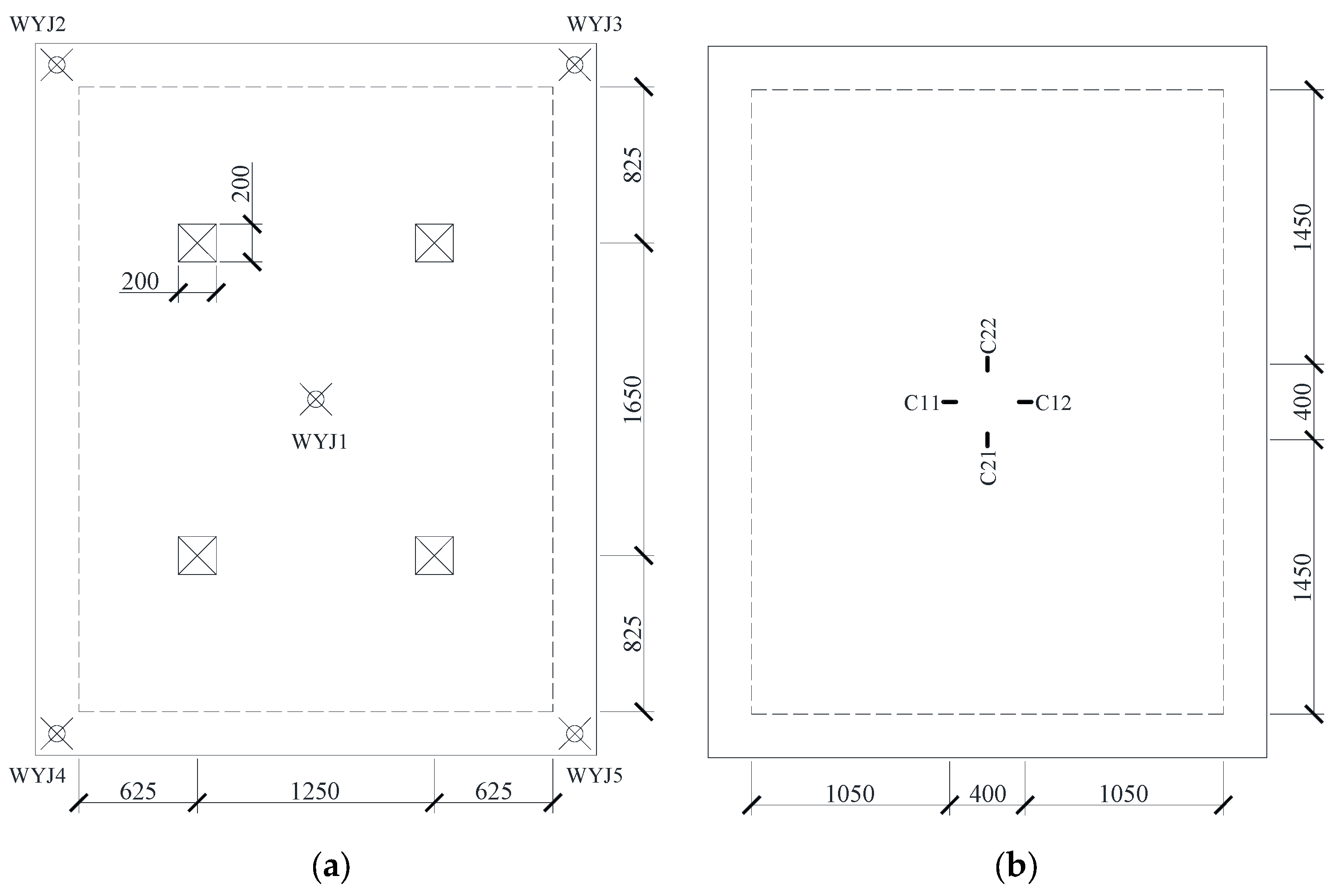
The loading points are positioned at the quarter-span locations of the slab, as shown in Figure 7a. A set of five displacement transducers WYJ1–WYJ5 (DongHua Testing Technology Co., Ltd, Jingjiang, China) were deployed at the midspan and corner points of the edge beams. Midspan deflection was calculated as the displacement at WYJ1 minus the average compression of elastomeric bearings at corners (i.e., the average of WYJ2–WYJ5 readings). Concrete strain gauges were installed on the top surface of the slab to capture bidirectional bending behavior, as illustrated in Figure 7b.
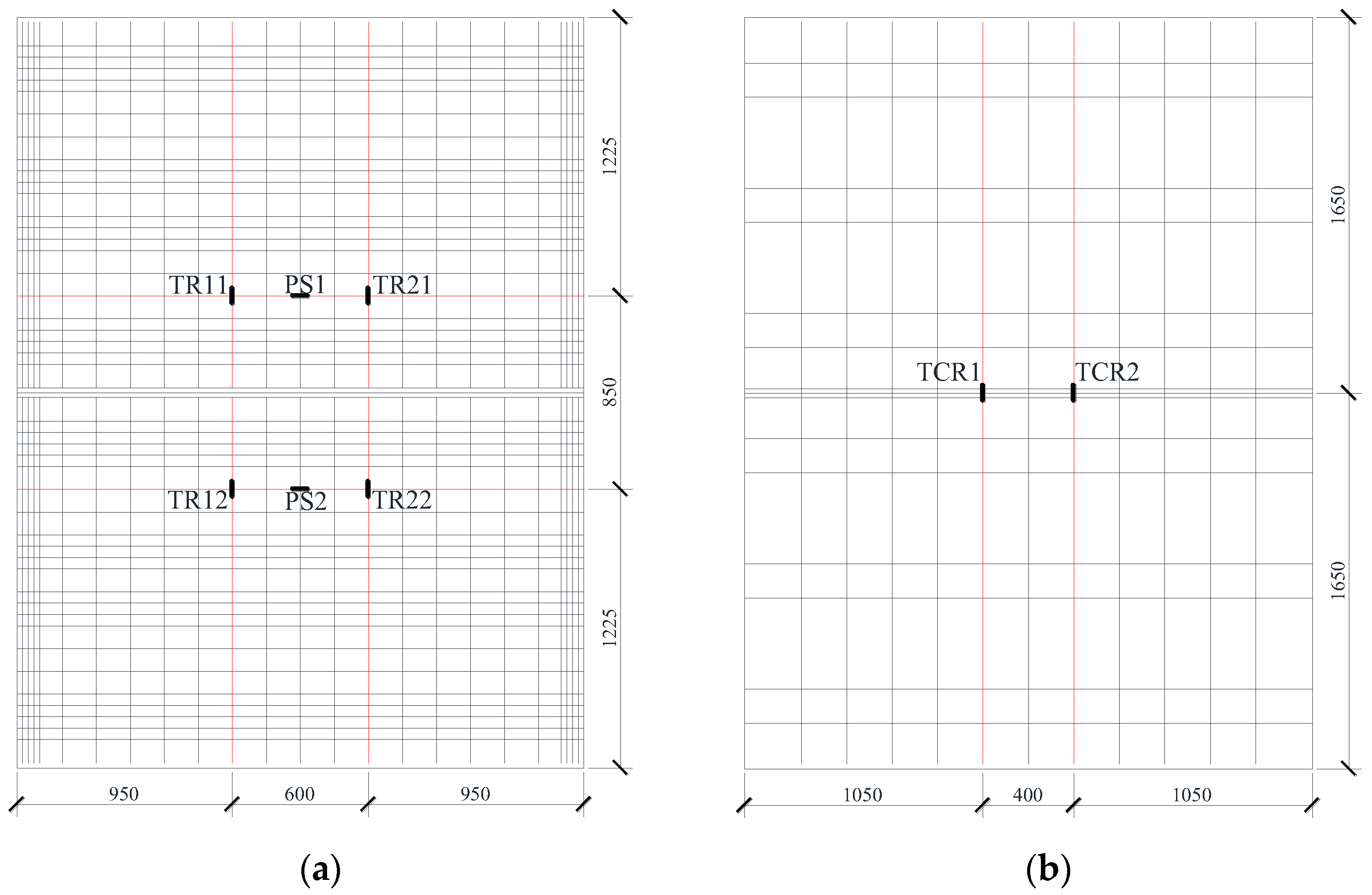
The strain gauge arrangement for reinforcement in the double-spliced slab is detailed in Figure 8. For clarity, the monitored reinforcement is highlighted in red. In the precast base slab, longitudinal prestressing steel was instrumented with strain gauges labeled as PS1 and PS2; transverse distribution rebars featured four measurement points, labeled as TR11, TR12, TR21, TR22, as shown in Figure 8a. Transverse distribution rebars were also monitored at TCR1 and TCR2, as shown in Figure 8b.
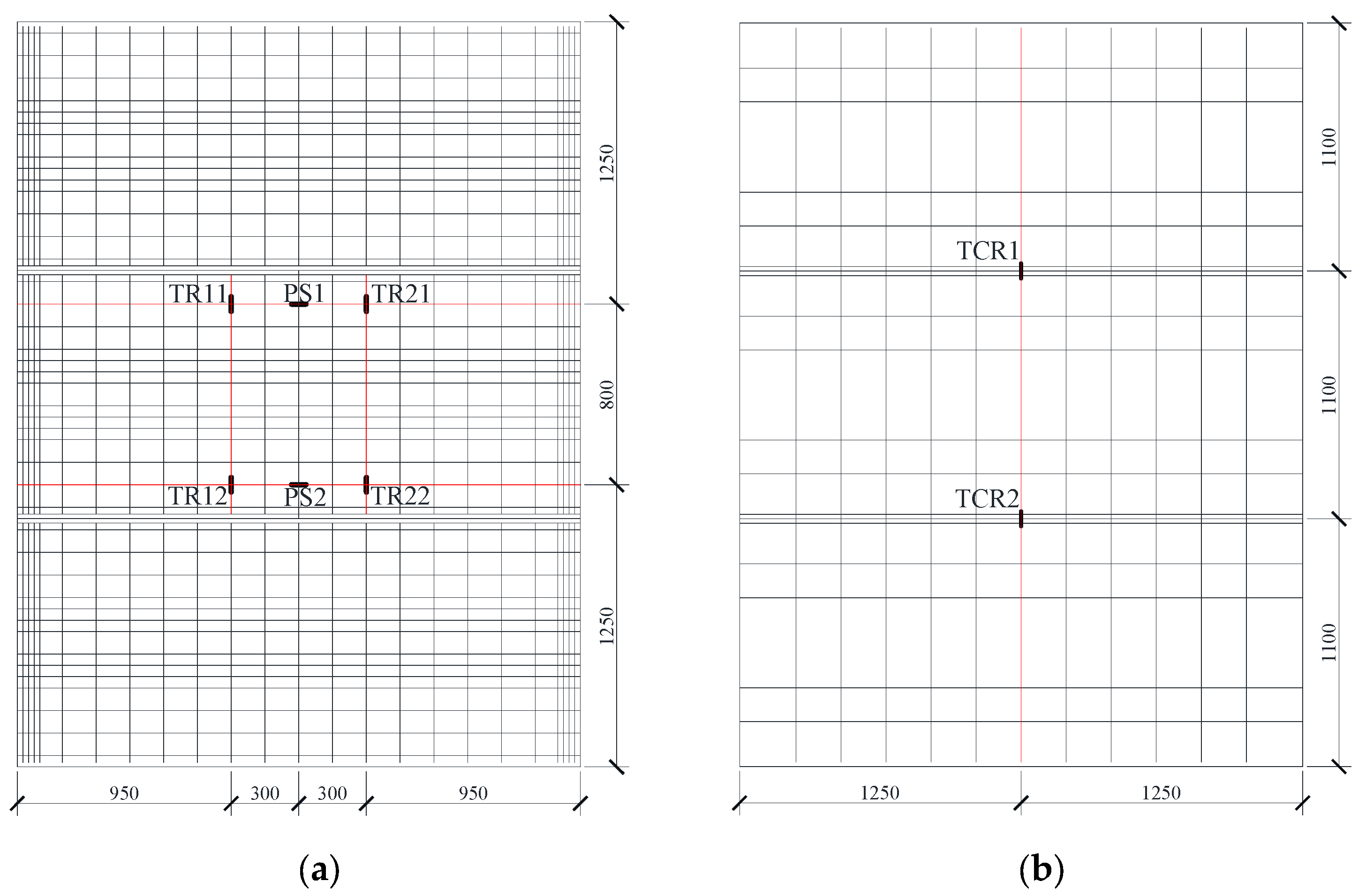
The strain gauge arrangement for reinforcement in the triple-spliced slab is shown in Figure 9. For clarity, the monitored reinforcement is highlighted in red. The instrumentation of longitudinal prestressing steel and transverse distribution rebars in the precast base slab is identical to that of the double-spliced slab. The joint-crossing continuous rebars were monitored at TCR1 and TCR across the splicing joints.

3. Experimental Results

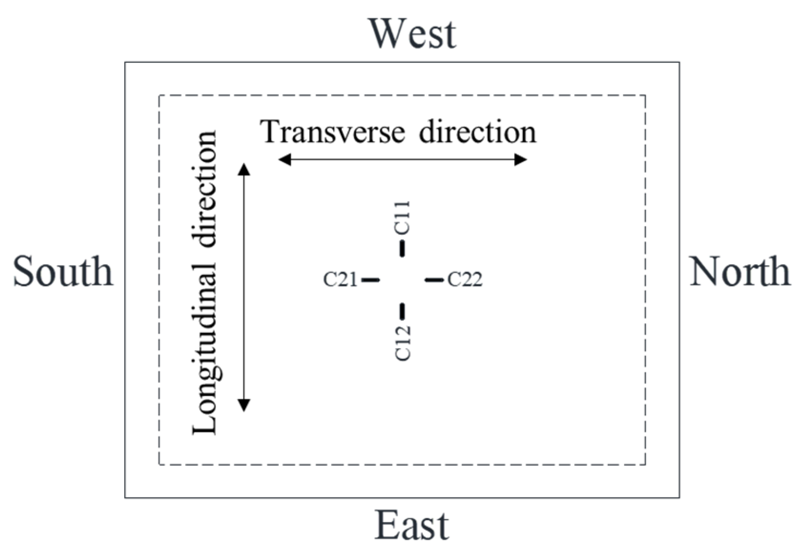
For clarity in subsequent experimental result descriptions, the orientation for bidirectional composite slabs is defined in Figure 10.

3.1. Double-Spliced Steel-Ribbed Bidirectional Composite Slab

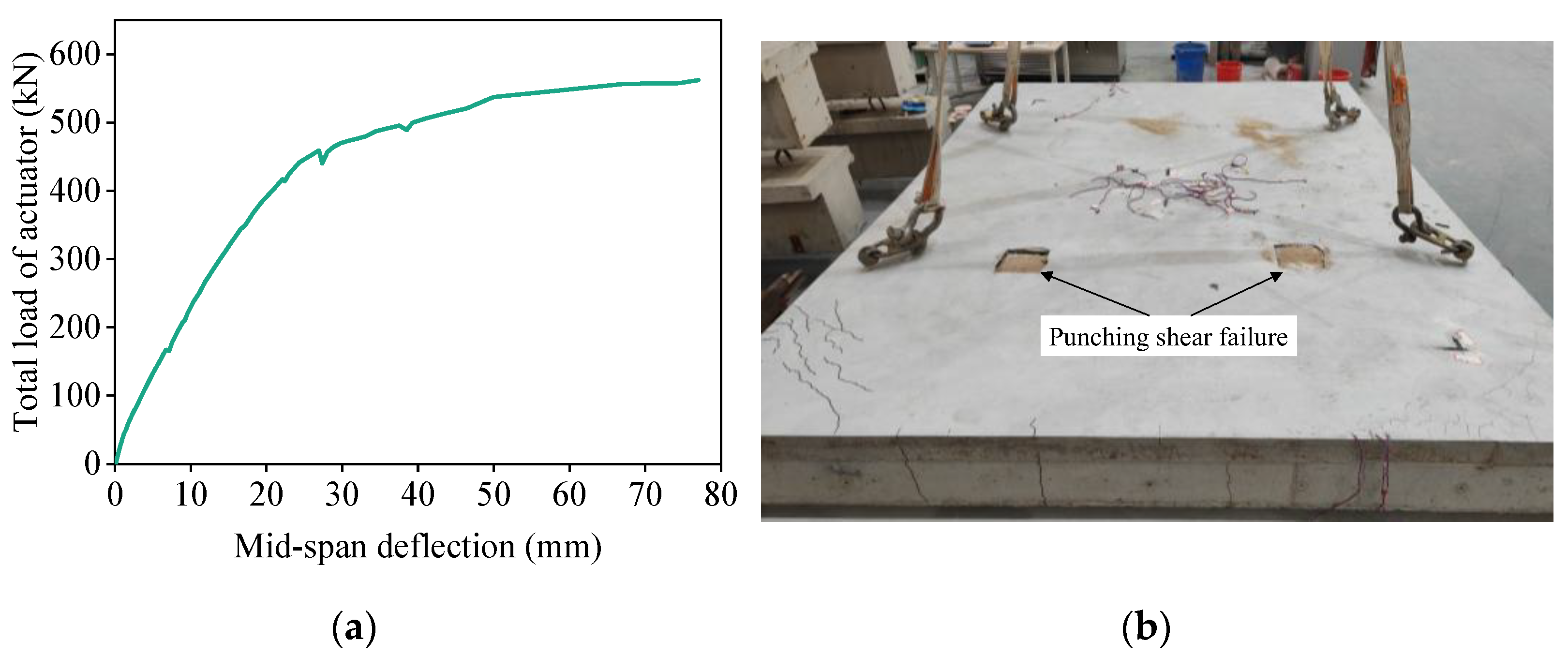
The load–midspan deflection curve of the double-spliced composite slab during loading is shown in Figure 11a, where the load represents the total actuator load (i.e., vertical resultant force at four loading points). As observed, the curve is approximately linear within the range of 0–250 kN, after which the stiffness gradually decreases. At around 420 kN, a distinct inflection point appears in the curve, indicating a marked reduction in stiffness. At 500 kN, the load–deflection curve begins to flatten, indicating that the slab stiffness was almost completely exhausted. Ultimate failure occurred at 565.3 kN, accompanied by a maximum midspan deflection of about 77.0 mm. The failure mode was dominated by punching shear beneath the north-side loading point on the slab’s top surface (Figure 11b), together with severe concrete spalling observed on the corresponding bottom surface.
Figure 12 presents bottom surface crack distribution of the double-spliced composite slab at failure. The midspan region exhibited an overall orthogonal crack pattern, with north–south cracks being denser than east–west cracks. Pronounced diagonal cracks were observed at all four corners. The crack propagation sequence was as follows: (1) At 250 kN, uniformly distributed east–west cracks initiated in the midspan and propagated with increasing load. (2) At 350 kN, east–west cracks extended toward edge beams, accompanied by new north–south and diagonal cracks at the northeast corner. (3) At 420 kN, cracks multiplied and extended further in both north–south and diagonal directions. (4) At 500 kN, intensified orthogonal cracking dominated the midspan, with diagonal cracks forming at all corners. (5) At 565.3 kN, concrete spalling occurred at the northern side (see red lines in Figure 12b), preceding the final failure. This cracking progression demonstrates a distinct bidirectional bending response, consistent with stiffness degradation reflected in Figure 11a.
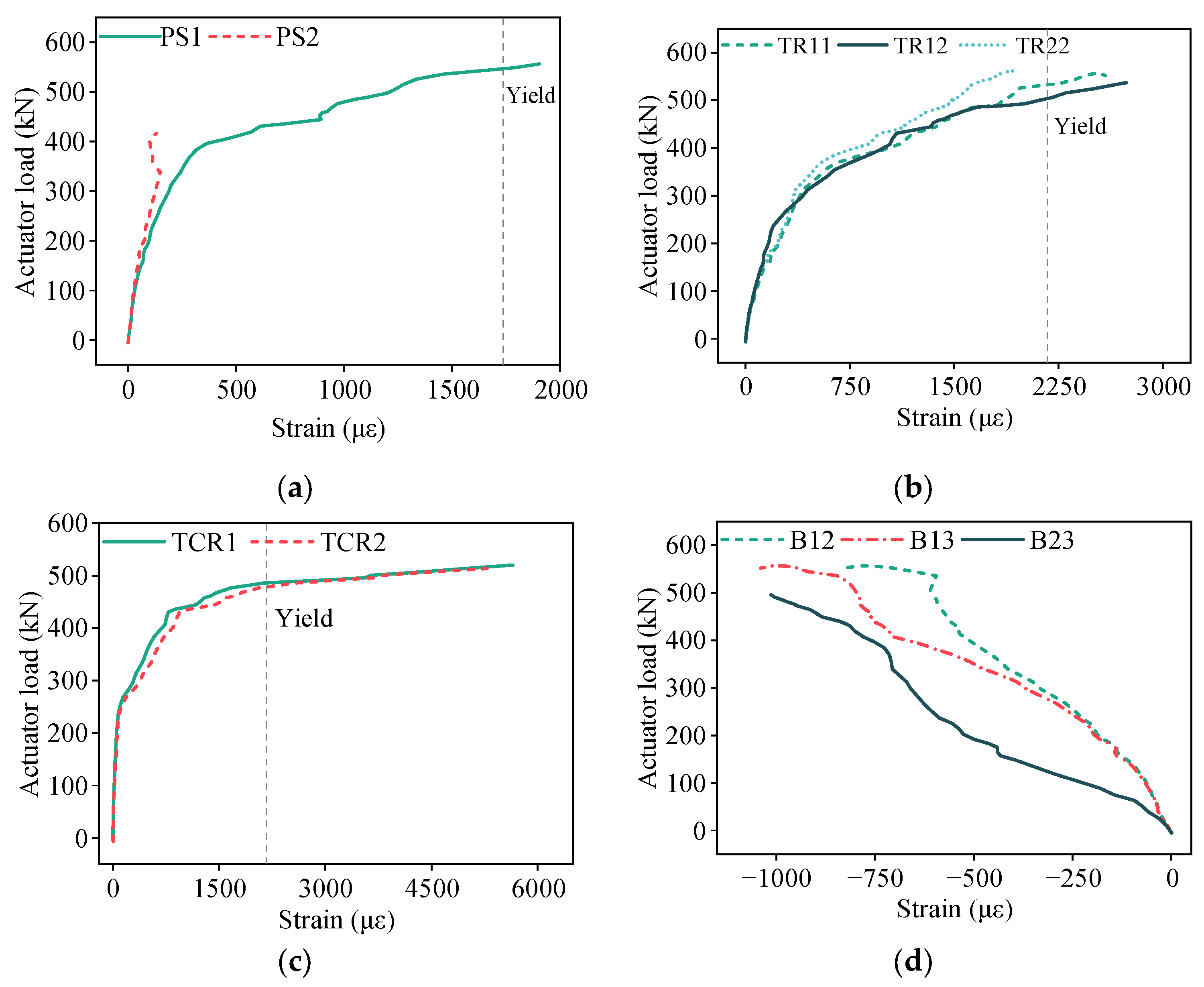
To further elucidate the failure mechanism and force-transfer behavior at joints, the load–strain responses of both reinforcement and concrete were plotted, as shown in Figure 13. Figure 13a shows the strain increments of prestressing steel during test, with initial effective tensile stress measured at 1136.589 MPa. During early loading stages, the prestressing steel strains of PS1 and PS2 increased linearly with loading. At around 100 kN, the strains began to rise more rapidly, indicating the initiation of micro-cracks in the north–south direction, perpendicular to the prestressing steel. Beyond 420 kN, measuring point PS2 failed while the load–strain curve of PS1 exhibited a pronounced inflection point with rapid strain escalation, corresponding to accelerated propagation of the north–south cracks. At failure, the maximum measured strain increment at PS2 reached 1904 με. The corresponding average stress σ P S was calculated in Equation (1), confirming the yielding of prestressing steel.
σ P S = 1136.589 + 1904 × 10 6 × 1.96 × 10 5 = 1509   MPa
Figure 13b illustrates the strain responses of the transverse distribution rebars in the precast base slab. Measuring point TR21 was damaged before testing. During early loading stages, TR11, TR12, and TR22 all exhibited nearly linear strain progression. When the applied load reached 250–300 kN, distinct inflection points emerged in their strain curves, followed by rapid strain growth under increasing load. This phenomenon corresponded to the development of east–west cracks in midspan regions. At failure, the maximum recorded strains at TR11, TR12, and TR22 were 2587 με, 2738 με, and 1928 με, respectively. The corresponding average stress σ T D R , calculated by Equation (2), indicated yielding of the transverse distribution reinforcement.
σ T D R = 2738 + 2587 + 1928 3 × 10 6 × 1.88 × 10 5 = 455   MPa
Figure 13c illustrates the strain measurements of the transverse continuous reinforcement across the joint interface. During early loading stages, the strain progressions of TCR1 and TCR2 were negligible. Upon reaching approximately 250 kN, distinct inflection points emerged in both load–strain curves, signifying the onset of cracking along the joint’s upper edge. Between 180 and 420 kN, the strains increased almost linearly. Beyond 420 kN, strain increments accelerated significantly and reached yielding at around 450 kN, after which the curves plateaued. At failure, strains at TCR1 and TCR2 reached 5650 με and 5285 με, respectively, well above the yield strain threshold.
Figure 13d illustrates the concrete strain distribution on the slab top surface. Measuring point C22 was damaged prior to testing. The remaining measuring points C11, C12, and C21 exhibited predominantly linear strain progression during loading. At failure, the maximum compressive strains were 840 με, 1040 με, and 1013 με, respectively—all below the crushing threshold. Notably, strain development at C21 was slightly more rapid than at C11 and C12, primarily due to the reduced transverse integrity induced by the splicing joint.

3.2. Triple-Spliced Steel-Ribbed Bidirectional Composite Slab

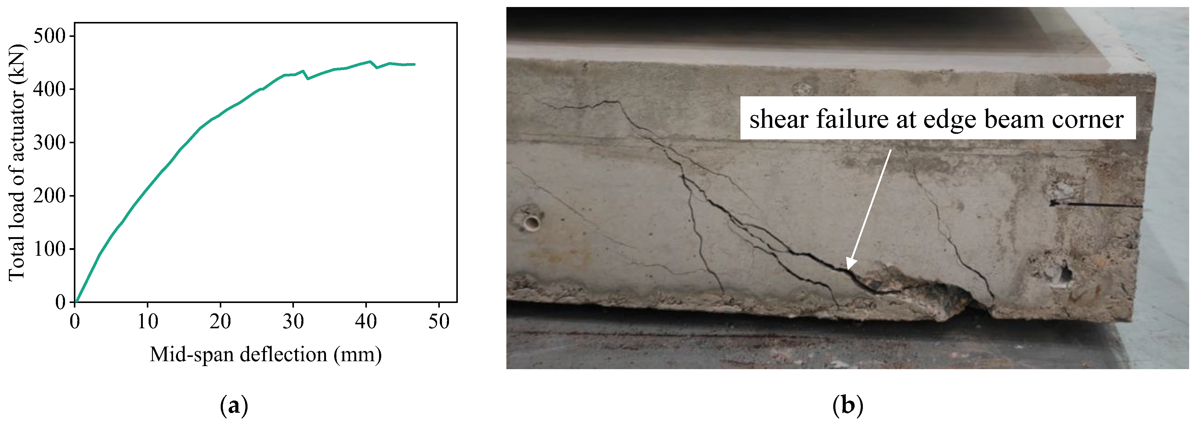
The load–midspan deflection curve of the triple-spliced slab is shown in Figure 14a. As observed, the curve exhibits s quasi-linear trend up to 140 kN, after which stiffness gradually decreases. Beyond 330 kN, the rate of stiffness degradation accelerates. Upon reaching 420 kN, a distinct inflection point emerges with the curve approaching a plateau, indicating near-total loss of structural stiffness. Ultimate failure occurred at 453.8 kN with a maximum midspan deflection of approximately 46.6 mm. The failure manifested as shear failure at the north support region, as depicted in Figure 14b.
Figure 15 depicts the bottom surface crack distribution of the triple-spliced slab at failure. The central slab primarily exhibited north–south oriented cracks, whereas the edge slabs developed diagonal cracks at corners. East–west cracks were sparsely distributed in the midspan region. The crack propagation sequence evolved as follows: (1) At 140 kN, uniformly distributed east–west cracks initiated in the midspan region; (2) At 300 kN, east–west cracks propagated further, with some extending to the edge beams; (3) At 330 kN, north–south cracks emerged, accompanied by diagonal cracks at all four corners; (4) At 400 kN, north–south and diagonal cracks intensified, with substantial length extension; (5) At 453.8 kN, shear failure occurred at the edge beam corner, accompanied by dense cracking at the slab-girder interface (see red lines in Figure 15b). The crack pattern indicates partial bidirectional bending response due to load transfer discontinuity between the central and edge slabs. The central slab primarily carried longitudinal bending moments, whereas the edge slabs exhibited significant stress concentrations at the corners. This cracking progression closely aligns with stiffness degradation reflected in Figure 14a.
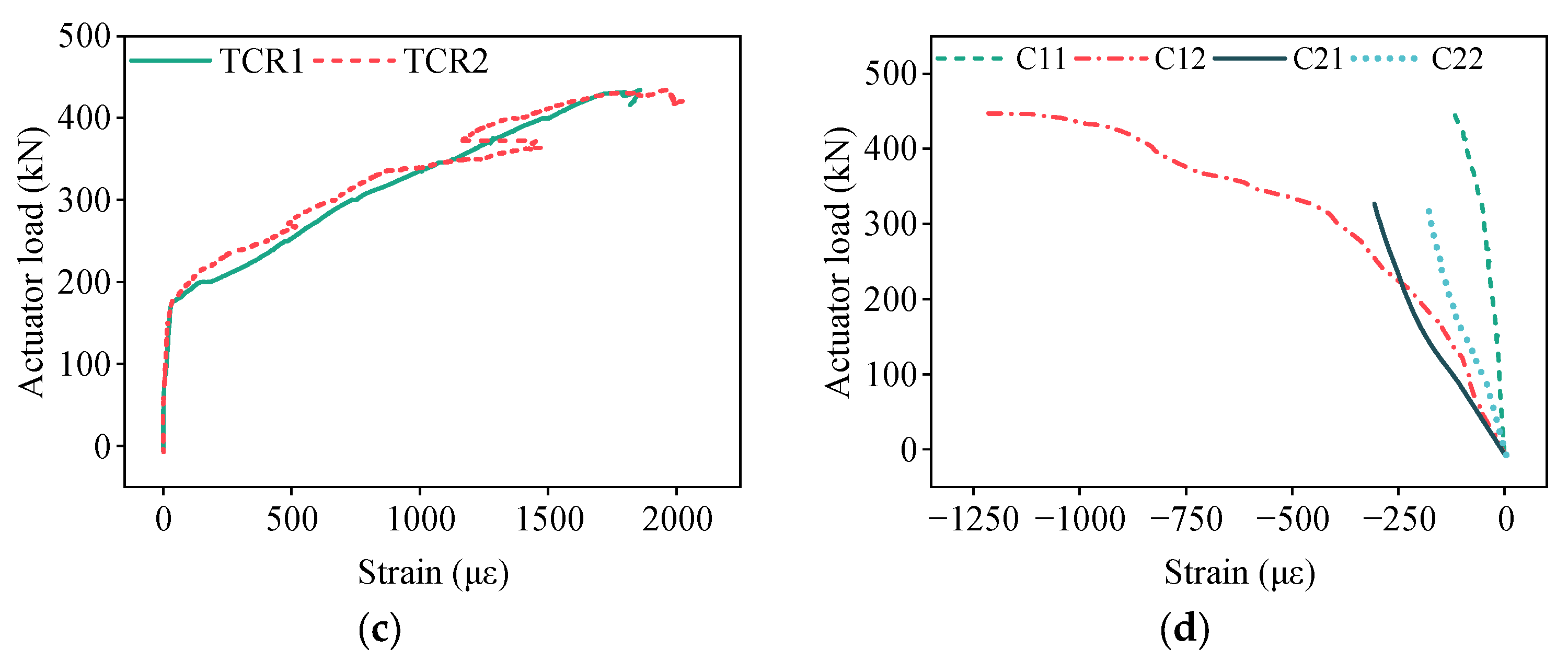
Figure 16 illustrates the load–strain responses of both reinforcement and concrete in the triple-spliced slab. Figure 16a displays the strain increments of prestressing steel during the test, with the initial effective tension stress measured at 1146.952 MPa. During early loading stages, the prestressing steel strains of PS1 and PS2 increased linearly. At 140 kN, the strains of PS1 and PS2 progressively increased, indicating the initiation of micro-cracks in the north–south direction, perpendicular to the prestressing steel. Beyond 320 kN, the load–strain curve of PS1 and PS2 exhibited pronounced inflection points with rapid strain escalation, corresponding to accelerated propagation of the north–south cracks. At failure, the maximum measured strain increment at PS1 and PS2 reached 1670 με, 1552 με, respectively. The corresponding average stress σ P S approached the yield strength, as computed via Equation (3).
σ P S = 1146.952 + 1670 + 1552 2 × 10 6 × 1.96 × 10 5 = 1463   MPa
Figure 16b illustrates the strain responses of the transverse distribution rebars in the precast base slab. During early loading stages, all measuring points exhibited essentially linear strain progression. At approximately 140 kN, inflection points appeared in the load–strain curves of measuring points TR11, TR12, TR21, and TR22, accompanied by transient strain accelerations coinciding with the east–west crack formation in the midspan region. Strain progression subsequently resumed near-linear progression, with deceleration observed beyond 250 kN, indicating reduced transverse load-bearing participation. At failure, the maximum recorded strains at TR11, TR12, TR21, and TR22 reached 685 με, 670 με, 535 με, and 628 με, respectively. The corresponding measured average stress σ T D R remained below the yield strain threshold, as computed via Equation (4).
σ T D R = 685 + 670 + 535 + 628 4 × 10 6 × 1.88 × 10 5 = 118   MPa
Figure 16c depicts the strain development in the transverse continuous reinforcement across joints. Initial strain increments were negligible until the test load reached approximately 180 kN. At this load, pronounced inflection points emerged in the load–strain curves of TCR1 and TCR2, indicating the onset of cracking along the joints. Subsequently, strains maintained essentially linear growth until failure. At failure, strains at TCR1 and TCR2 reached 1858 με and 2018 με, respectively. The corresponding measured average stress σ T D R , as computed via Equation (5), approached but did not exceed yield strength.
σ T C R = 1858 + 2018 2 × 10 6 × 1.88 × 10 5 = 364   MPa
Figure 16d illustrates the concrete strain distribution on the slab top surface. Initially, strain progression was predominantly linear across all measuring points. Beyond 320 kN, strain growth at C12 accelerated significantly compared to other measuring points, indicating longitudinal bending dominance in the midspan region. This behavior also corresponds to the predominance of north–south oriented cracks in this zone. At ultimate failure, the maximum compressive strain recorded was 1225 με without concrete crushing.

3.3. Discussion of Experimental Results

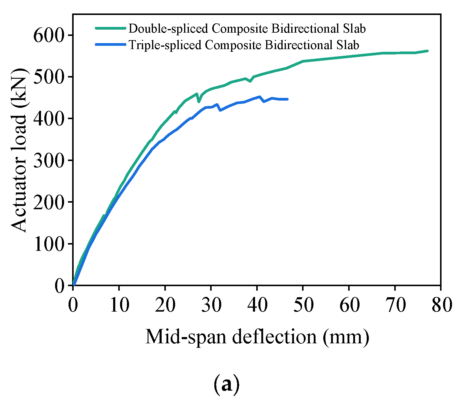
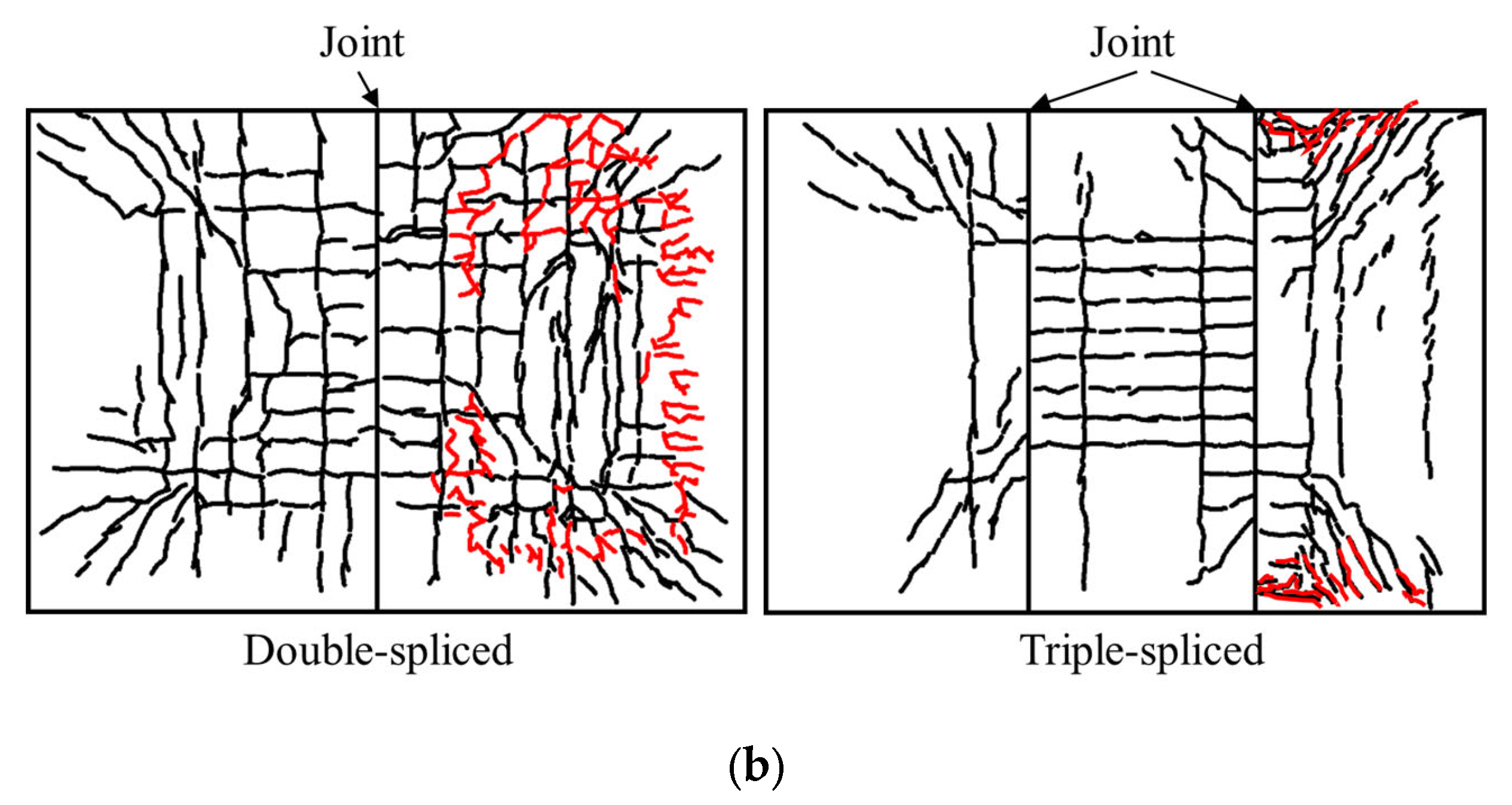
Figure 17 compares load–deflection curves and crack patterns for double-spliced and triple-spliced slabs. It can be seen that the double-spliced slab demonstrated superior overall mechanical performance versus triple-spliced composite bidirectional slabs, exhibiting a 24.5% increase in ultimate load-carrying capacity, 65.3% improvement in ductility, and significantly enhanced post-cracking stiffness beyond 200 kN. The double-spliced slab exhibited a clear bidirectional bending response, characterized by an orthogonal crack pattern in the midspan region and simultaneous yielding of both the longitudinal prestressing steel and the transverse distribution reinforcement at failure. In contrast, the triple-spliced slab, with reduced transverse continuity due to multiple joints, displayed a less pronounced two-way load-carrying mechanism. The central slab primarily resisted longitudinal bending with dense north–south oriented cracks, while stresses in the edge slabs concentrated at the corners triggered shear failure. At failure, longitudinal prestressing steel in the central slab approached yielding, yet transverse reinforcement averaged only 118 MPa stress (utilization rate: 29%). These findings indicate that increased joint quantity diminishes transverse continuity, reduces load-bearing capacity, and degrades structural behavior from bidirectional to unidirectional load-bearing.
Regarding the transverse load-transfer mechanisms at the splicing joints, both double- and triple-spliced slabs exhibit significantly higher strain in the transverse continuous reinforcement crossing the joints compared to the transverse distribution reinforcement within the precast base slab. The strain ratios, defined as the ratio of the maximum strain in the joint-crossing reinforcement to the corresponding strain in the transverse distribution reinforcement at failure, reach 2.3:1–3.1:1, as illustrated in Figure 18. Due to the maximum transverse bending moment at midspan, the double-spliced slab with single midspan splicing joint demonstrates synchronized strain development between joint-crossing and transverse distribution reinforcement during early-to-mid loading stages. Conversely, the triple-spliced slab exhibits lagged strain in joint-crossing reinforcement relative to midspan transverse distribution reinforcement, reducing transverse force transmission efficiency. For high-load zones in engineering practice, double-spliced slabs are recommended to enhance bidirectional force-bearing performance; if double-spliced slabs must be employed, transverse reinforcement at joints should be strengthened to improve transmission efficiency.

4. Finite Element Modeling and Parametric Analysis

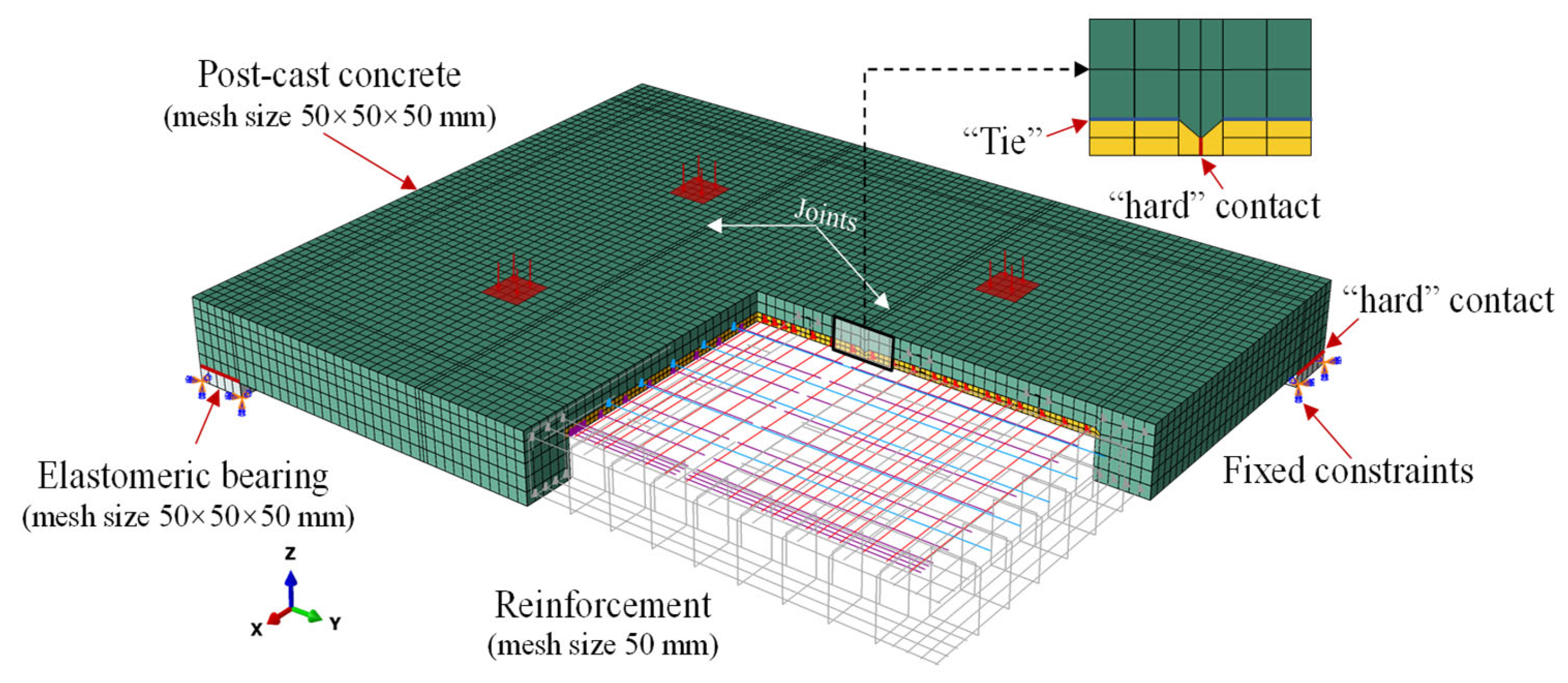
Due to practical constraints of full-scale specimen fabrication and testing in the 500 kV substation project, only one specimen for each joint type was tested. To provide deeper insights into the bidirectional bending performance, finite element (FE) models of the double-spliced, triple-spliced, and cast-in-place monolithic composite slabs were developed using Abaqus [29]. The modeling methodology is illustrated in Figure 19. In the models, the concrete parts, steel ribs, and elastomeric bearings were modeled using solid elements (C3D8R), while reinforcement (rebar and prestressing steel) was modeled with truss elements (T3D2). The reinforcement was “embedded” in the concrete with a mesh size of approximately 50 mm. Consistent mesh sizes of 50 × 50 × 50 mm were applied to the post-cast concrete layer, edge beams, and elastomeric bearings, while finer meshes of 20 × 25 × 25 mm, 1 × 10 × 20 mm, and 20 × 50 × 50 mm were applied to the precast base slab, steel ribs, and upper concrete flange, respectively. The structural integrity of the composite slabs under loading is particularly critical at the interfaces between the precast and post-cast concrete layers. Based on experimental results, the existence of the inverted T-shaped ribs and surrounding edge beams can effectively enhance the bonding between the laminated concrete layer. As a result, the interaction between the precast base slab and the post-cast concrete layer was set as “tied” with no relative slip. The elastomeric bearings are arranged at the corners of the edge beams, with the vertical interaction defined as “hard” contact and the tangential interaction modeled using a friction coefficient of 0.3. The joints of the spliced slabs were also modeled as “hard” contact and allowed separation. The bottom surfaces of the bearings were fixed during loading. The external load is applied to the top surface of the structure in the form of pressure.
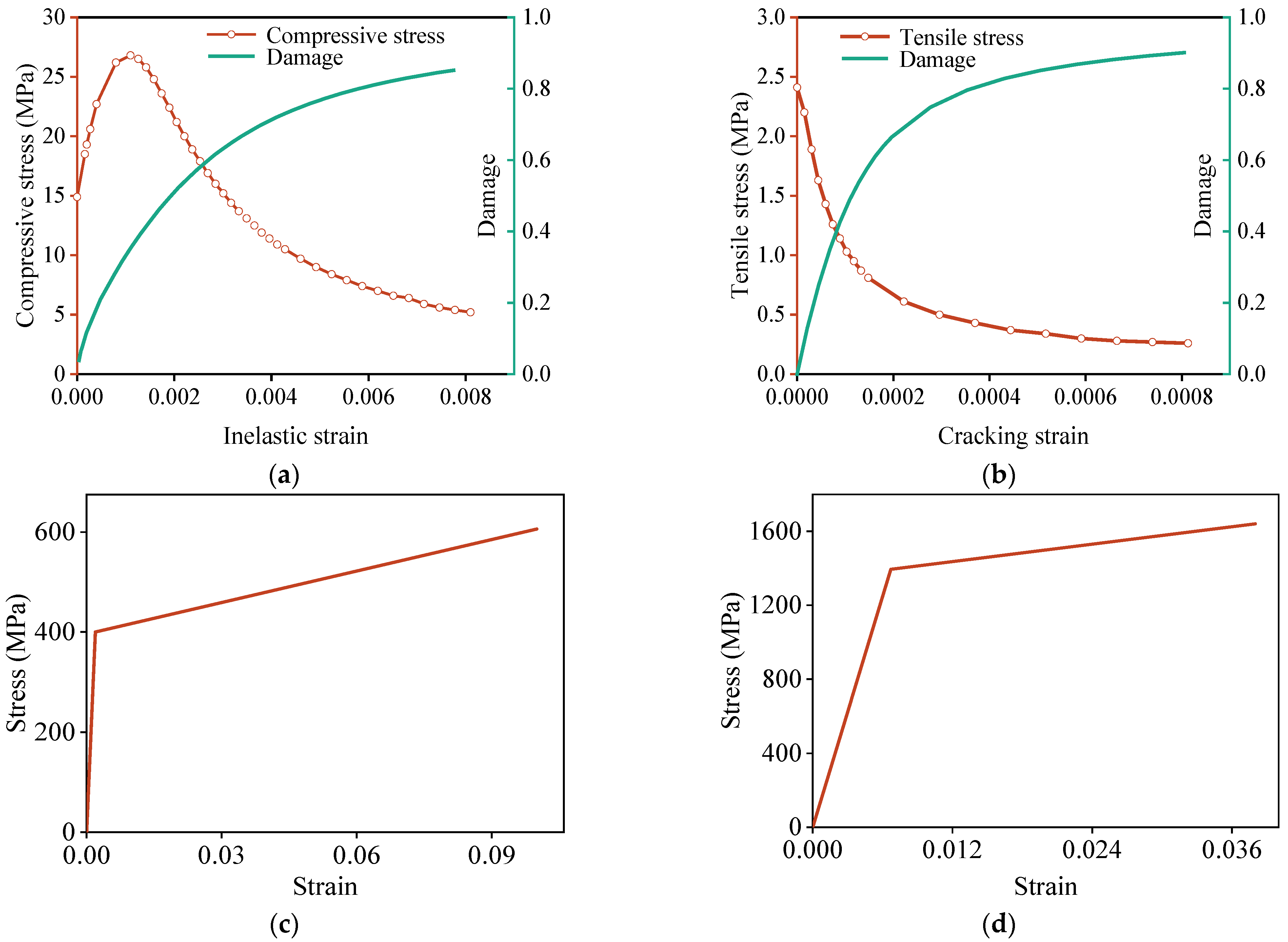
The constitutive model for concrete employs the concrete damage plasticity (CDP) model, with the required parameters specified in Table 2. The dilation angle was set to 30°, and the flow potential eccentricity to 0.1, indicating nearly constant dilation over a wide range of confining pressures. The parameter fb0/fc0 denotes the ratio of biaxial to uniaxial compressive yield stresses, reflecting the characteristics of the failure function. K represents the ratio of the second stress invariant on the tensile meridian to that on the compressive meridian at initial yield, reflecting the relative contribution of tensile and compressive stress states. The viscosity parameter is a numerical factor used to improve convergence during simulation of concrete softening and cracking. The responses and corresponding damage of concrete under uniaxial compression and tension are illustrated in Figure 20a,b, neglecting creep and shrinkage effects. For rebar and prestressing steel, the bilinear model is adopted with elastic modulus reduced to 1% in the plastic stage, as shown in Figure 20c,d. The elastomeric bearings experience relatively low stress throughout loading and remain linearly elastic, with an assigned elastic modulus of 30 MPa.
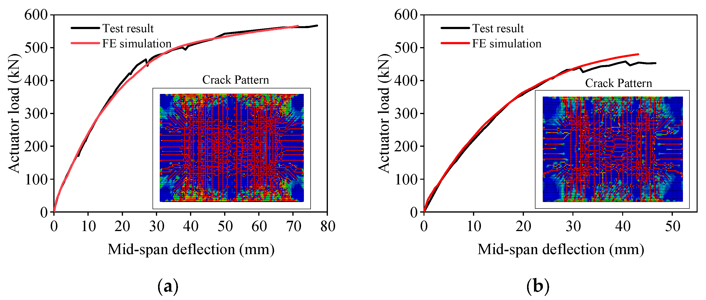
To verify the validity and accuracy of the FE modeling methodology, the calculated results of the double- and triple-spliced slabs are compared with the experimental data, as shown in Figure 21. The FE models demonstrate excellent agreement with experimental results in terms of stiffness and bearing capacity, showing an average error within 5%. For the ultimate deflection, the FE models exhibited a slightly smaller ultimate deflection compared with the test results, with a maximum deviation of approximately 7%. This discrepancy may be attributed to the assumption of perfect bonding between the precast and post-cast concrete layers in simulation analysis. The cracking patterns are also consistent with the experimental observations in Figure 17b.
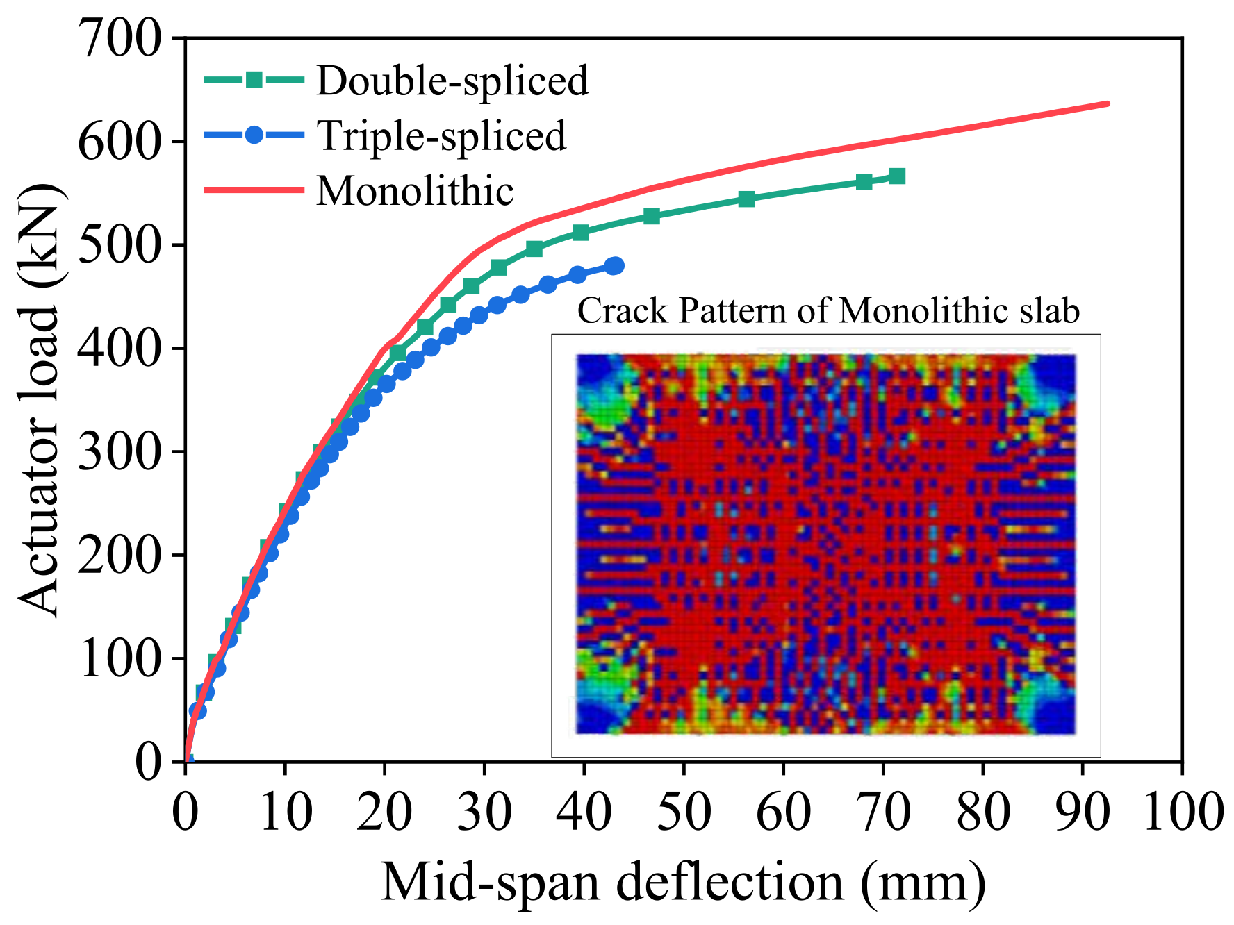
The load–deflection responses of the spliced and cast-in-place monolithic slabs are further compared in Figure 22. Overall, all specimens exhibit similar nonlinear characteristics, characterized by an initial nearly linear stage followed by stiffness degradation and progressive plastic deformation. With prestressing tendons arranged only in the east–west direction parallel to the splice joints, the slabs lack prestress restraint in the perpendicular direction. As a result, east–west cracks are the first to develop and dominate the cracking pattern in the initial loading stage for both monolithic and spliced slabs. Consequently, all specimens show nearly identical initial stiffness, indicating that splicing has little effect during the onset of cracking. With increasing deflection, however, north–south and diagonal cracks develop, resulting in notable differences between the monolithic and spliced slabs. For the monolithic slab, cracks are more sufficiently developed, more uniformly distributed, and extend in both directions, reflecting a more pronounced bidirectional load-bearing mechanism. By contrast, the presence of splice joints in composite slabs reduces overall integrity and accelerates localized damage, resulting in lower post-crack stiffness in the mid-to-late loading stage and failure load. Quantitatively, the double- and triple-spliced slabs reach ultimate loads of 567 kN (565.3 kN in the test) and 480 kN (453.8 kN in the test), respectively, compared with about 636 kN for the monolithic slab. In terms of ductility, the ultimate midspan deflections of the double- and triple-splice slabs are 43.14 mm (46.6 mm in the test) and 71.40 mm (77.0 mm in the test), respectively, also lower than that of the monolithic slab, which measures 92.4 mm. These results clearly demonstrate that increasing the number of splices leads to a progressive reduction in both load-bearing capacity and ductility. Notably, the ductility of the triple-spliced composite slab could be significantly improved if local reinforcement enhancement were provided at edge beam corners to prevent premature edge failures.
To capture multiple failure modes and quantify the effects of key design variables, a parametric study was carried out. Four parameters were considered here: prestressing ratio, concrete grade, strength and diameter of the joint-crossing reinforcement. Three distinct failure modes were identified first, as shown in Figure 23: (1) yielding of the longitudinal prestressing steel; (2) concrete crushing; (3) joint failure, i.e., yielding of the transverse joint-crossing reinforcement.
The parametric analysis results of the triple-spliced slab are presented in Figure 24a–d, while the double-spliced slab shows similar trends and is omitted for brevity. Failure labels P, C, and J denote the governing failure modes of prestressing steel yielding, concrete crushing, and joint-crossing reinforcement yielding, respectively. As can be seen from Figure 24, the longitudinal prestressing ratio exerts the greatest influence on slab behavior, followed by the diameter of the joint-crossing reinforcement and the concrete strength, while the effect of the joint-crossing reinforcement strength is comparatively minor. Specifically, as prestressing ratio rises from 0.072% to 0.394%, the ultimate bearing capacity increases monotonically, but the marginal gains gradually diminish at higher ratios. The governing failure mode transitions from prestressing tendon yielding to joint-controlled failure, as shown in Figure 24a. Insufficient yield strength (≤235 MPa) or small diameter (≤4 mm) triggers joint-controlled failure in the triple-spliced slab, leading to a marked reduction in both ultimate capacity and ductility, as illustrated in Figure 24b,c. Enhancing either the strength or diameter delays joint failure and shifts the governing mechanism back to prestressing steel yielding. Compared to the strength, diameter enlargement proves significantly more effective than strength enhancement in improving overall performance. Increasing the concrete strength brings only a limited improvement in the slab’s load-bearing capacity, especially for grades C30 and above, and causes a reduction in the slab’s ductility, as shown in Figure 24d. For the bidirectional slab made of C20 concrete, the concrete is close to collapse when the prestressed tendons yield, while the failure modes for C30, C40, and C50 are only controlled by the yielding of the prestressing steel. Maintaining an adequate prestressing ratio and avoiding undersized or low-grade joint reinforcement are the most effective measures to prevent premature joint-controlled failures and enhance structural performance. Accordingly, a concrete strength of C30 or higher is recommended.

5. Conclusions

This study examines the bidirectional bending performance of double-spliced and triple-spliced steel-ribbed composite slabs for substation applications. The following conclusions were drawn:
(1)
Compared to the triple-spliced slabs, double-spliced slabs exhibited a 24.5% increase in ultimate load-bearing capacity and a 65.3% improvement in ductility under given bidirectional bending conditions in this paper. Double-spliced slabs demonstrated typical bidirectional behavior, with well-developed orthogonal crack pattern and yielding of both longitudinal prestressing steel and transverse reinforcement at failure. Triple-spliced slabs showed only partial bidirectional bending response due to poorer transverse integrity. Upon failure, longitudinal prestressing steel approached yielding while transverse reinforcement exhibited low stress levels.
(2)
Compared with the monolithic spliced slabs, the spliced slabs exhibited nearly identical stiffness at the onset of cracking, but their stiffness progressively declined during the mid-to-late loading stages, ultimately leading to lower load-bearing capacity and ductility at failure. Joint-crossing reinforcement was confirmed to be the main path for transverse load transfer. The strains in the joint-crossing reinforcement at failure were significantly higher than those in the transverse distribution rebars, with a ratio of about 2.3:1–3.1:1. Increased joint quantity will reduce transverse continuity and load transfer, degrading load capacity and ductility.
(3)
Parametric analysis shows that the longitudinal prestress ratio has the greatest influence on the behavior of spliced slabs, followed by the diameter of the joint-crossing reinforcement and the concrete strength, while the effect of the joint-crossing reinforcement strength is comparatively minor. Increasing the prestressing ratio significantly enhances the ultimate bearing capacity and ductility, but the marginal gains diminish at higher ratios as the governing failure mode shifts from prestressing steel yielding to joint-controlled failure. Enlarging reinforcement diameter is more effective than increasing its strength in preventing premature joint failure. Increasing concrete strength offers limited capacity gains and may reduce ductility.
(4)
For engineering applications such as 500 kV prefabricated substations, double-spliced slabs are more preferable to enhance bidirectional bending performance, particularly in high-load zones. Triple-spliced slabs require careful attention to preventive measures, including local reinforcement at slab corners and optimized joint detailing. This study mainly focuses on the ultimate capacity and ductility of steel-ribbed composite slabs. Future work will address the serviceability and durability aspects of the floor system, including crack control under service loads, long-term joint slip, and rib corrosion, to ensure reliable life-cycle performance.

Author Contributions

Conceptualization, methodology, and writing—original draft, L.L. and Z.W.; investigation, and formal analysis, Y.L. and Y.J.; data curation, formal analysis, and writing—original draft, H.C.; supervision, writing—review and editing, funding acquisition, Y.Z.; validation, K.Z.; resources, project administration, K.R. and L.T. All authors have read and agreed to the published version of the manuscript.

Funding

This research was financially supported by the National Natural Science Foundation of China (52208178), and the Natural Science Foundation of Shandong Province (ZR2022QE128).

Data Availability Statement

The datasets generated during and/or analyzed during the current study are available from the corresponding author upon reasonable request.

Conflicts of Interest

Authors Lin Li, Zhenzhong Wei, Yong Liu and Yunan Jiang were employed by Shandong Electric Power Engineering Consulting Institute Co., Ltd. The remaining authors declare that the research was conducted in the absence of any commercial or financial relationships that could be construed as a potential conflict of interest.

References

  1. Luo, T.; Xue, X.L.; Wang, Y.N.; Xue, W.R.; Tan, Y.T. A systematic overview of prefabricated construction policies in China. J. Clean Prod. 2021, 280, 124371. [Google Scholar] [CrossRef]
  2. Bonamente, E.; Cotana, F. Carbon and energy footprints of prefabricated industrial buildings: A systematic life cycle assessment analysis. Energies 2015, 8, 12685–12701. [Google Scholar] [CrossRef]
  3. He, H.; Zhou, S.; Zhang, L.; Zhao, W.; Xiao, X. Dynamic accounting model and method for carbon emissions on the power grid side. Energies 2023, 16, 5016. [Google Scholar] [CrossRef]
  4. Bai, S.; Li, M.C.; Song, L.G.; Kong, R. Developing a common library of prefabricated structure components through graphic media mapping to improve design efficiency. J. Constr. Eng. Manag. 2021, 147, 04020156. [Google Scholar] [CrossRef]
  5. Jiang, Y.; Shu, J.P.; Ye, J.; Zhao, W.J. Virtual trail assembly of prefabricated structures based on point cloud and BIM. Autom. Constr. 2023, 155, 105049. [Google Scholar] [CrossRef]
  6. Zhao, Y.Y.; Li, R.; Yue, S.Y. Comparative Analysis of Modular Prefabricated Module Substation and Conventional Substation. In Proceedings of the 3rd International Conference on Cognitive Based Information Processing and Applications, Guangzhou, China, 2–3 November 2023. [Google Scholar] [CrossRef]
  7. Nie, J.G.; Jiang, Y.X.; Nie, X.; Zhuang, L.D. Effect of truss reinforcement on mechanical properties of prefabricated slabs. Build. Struct. 2021, 42, 151–158. [Google Scholar] [CrossRef]
  8. Zhou, G.Q.; Li, S.R.; Zhang, X.; Yang, X. Experimental study on mechanical behavior of prestressed concrete composite slab with steel-tube truss. Build. Struct. 2025, 55, 26–31. [Google Scholar] [CrossRef]
  9. Liu, J.P.; Hu, H.F.; Li, J.; Chen, Y.F.; Zhang, L. Flexural behavior of prestressed concrete composite slab with precast inverted T-shaped ribbed panels. Eng. Struct. 2020, 215, 110687. [Google Scholar] [CrossRef]
  10. Hou, H.T.; Liu, X.; Qu, B.; Ma, T.; Liu, H.; Feng, M.; Zhang, B. Experimental evaluation of flexural behavior of composite beams with cast-in-place concrete slabs on precast prestressed concrete decks. Eng. Struct. 2016, 126, 405–416. [Google Scholar] [CrossRef]
  11. Chen, X.D.; Ma, Q.Y. Experimental study on the flexural performance of concrete hollow composite slabs with tightly connected panel sides. Sci. Rep. 2024, 14, 20784. [Google Scholar] [CrossRef]
  12. Karimipanah, A.; Zeynalian, M.; Ataei, A. Structural performance of cold formed steel composite beams with profiled steel sheeting. Int. J. Civ. Eng. 2024, 22, 1099–1116. [Google Scholar] [CrossRef]
  13. Lu, L.F.; Ding, Y.Z.; Guo, Y.; Hao, H.L.; Ding, S.L. Flexural performance and design method of the prefabricated RAC composite slab. Structures 2022, 38, 572–584. [Google Scholar] [CrossRef]
  14. Lu, L.F.; Gao, M.; Guo, Y.; Wang, W.; Yan, H.W.; Jiang, T.S. Experiments on flexural behavior of the prefabricated RAC and NWC composite slab. Ain Shams Eng. J. 2022, 13, 101789. [Google Scholar] [CrossRef]
  15. Lu, L.F.; Wang, W.; Zhang, L.X.; Shao, Y.J. Longitudinal shear strength of recycled aggregate concrete prefabricated superimposed slabs. Eng. Struct. 2023, 281, 115745. [Google Scholar] [CrossRef]
  16. Stehle, J.; Kanellopoulos, A.; Karihaloo, B.L. Performance of joints in reinforced concrete slabs for two-way spanning action. Proc. Inst. Civil Eng. Struct. Build. 2011, 164, 197–209. [Google Scholar] [CrossRef]
  17. Cheng, Z.J.; Ma, Z.Z.; Hu, J.; Yu, S.L.; Zhao, Y. Experimental research on heap loading of reinforced concrete composite two-way slab with lattice girders and connected without gap. Build. Struct. 2021, 51, 111–119. [Google Scholar] [CrossRef]
  18. Wang, G.S.; Liu, J.H.; Zhang, Y.B.; Zhang, Z.Y.; Tao, J.W.; Wu, D.Y. Theoretical and experimental study on the stress state of joints in two-way composite slabs. Buildings 2024, 14, 3374. [Google Scholar] [CrossRef]
  19. Ciu, S.Q.; Liu, C.Q.; Liu, W.Z.; Shi, L. Research on experiment and calculating methods of flexural stiffness in direction perpendicular to separating-type joints for concrete composite slab. J. Build. Struct. 2018, 39, 75–84. [Google Scholar] [CrossRef]
  20. Chen, Y.H.; Lu, D.; Zhang, M.; Sun, H.W.; Xie, G.X. Research on connection technique for bidirectional composite floor slabs without gap. Ind. Constr. 2020, 50, 31–35. [Google Scholar] [CrossRef]
  21. Li, J.; Ni, D.Y.; Liu, X.; Zhang, J.R. Experimental study of mechanical properties of L-shaped joint laminated two-way slabs. Build. Struct. 2020, 50, 67–71+86. [Google Scholar] [CrossRef]
  22. Shill, S.K.; Garcez, E.O.; Al-Ameri, R.; Subhani, M. Performance of two-way concrete slabs reinforced with basalt and carbon FRP rebars. J. Compos. Sci. 2022, 6, 74. [Google Scholar] [CrossRef]
  23. Wang, Y.H.; Peng, Y.P. Force transfer mechanism analysis of CFRP-concrete two-way composite slab connected without gap under vertical load. Struct. Eng. 2024, 40, 107–115. [Google Scholar] [CrossRef]
  24. Lu, J.S.; Wu, J.H.; Zheng, Z.P. Structural design of precast reinforced concrete frame structure of Miaosan 110kV transformer substation. Build. Struct. 2014, 44, 24–28. [Google Scholar] [CrossRef]
  25. Liu, Y.; Wei, Z.Z.; Zheng, Y.C.; Jiao, J.F. Application exploration and practice of prestressed steel pipetruss floor slab in substation. Shandong Electr. Power 2021, 48, 39–43. [Google Scholar]
  26. Li, Z.D.; Tan, B.; Cheng, Z.; Xiong, M.Q. Application of prefabricated structure in substation industrialization project. Struct. Constr. 2021, 43, 228–231. [Google Scholar] [CrossRef]
  27. Lei, X.S.; Ouyang, J.W.; Wang, Y.F.; Wang, X.H.; Zhang, X.F.; Chen, F.; Xia, C.; Liu, Z.; Zhou, C.Y. Thermal–mechanical coupling evaluation of the panel performance of a prefabricated cabin-type substation based on machine learning. Fire 2021, 4, 93. [Google Scholar] [CrossRef]
  28. Li, L.; Liu, Y.; Wei, Z.Z.; Jiang, Y.N.; Chen, H.M.; Zhang, Y.; Liu, C.; Rong, K.J.; Tian, L. Numerical study on the bending performance of steel-ribbed composite slabs for substations. Appl. Sci. 2025, 15, 2876. [Google Scholar] [CrossRef]
  29. Abaqus, Computer Software. version 6.14. SIMULIA: Providence, RI, USA, 2014.
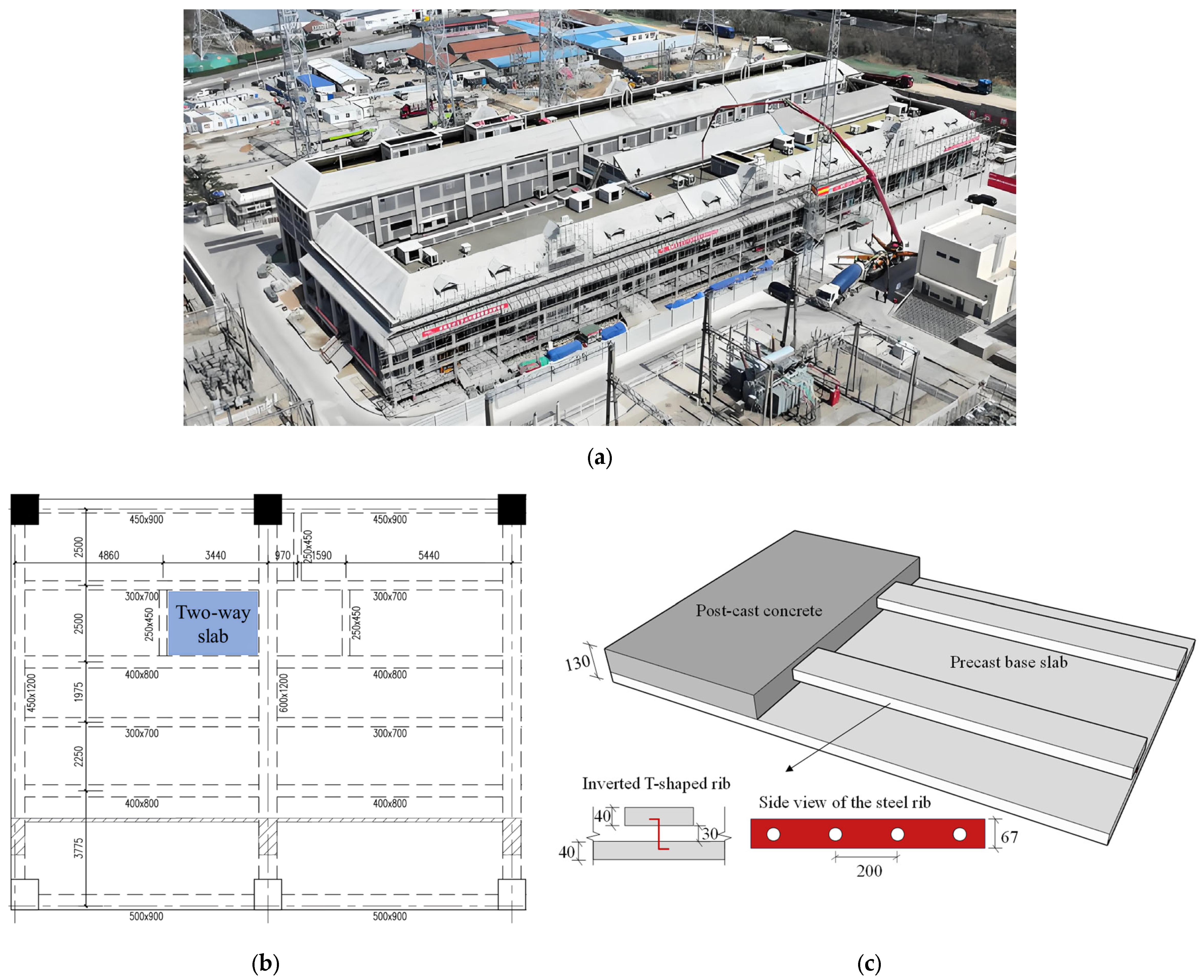
Figure 1. Daocheng (Huangbuling) 500 kV substation. (a) Aerial view. (b) Layout plan for the 8.800 m floor (mm). (c) Illustration of the steel-ribbed composite slab (mm).
Buildings 15 03540 g001
Figure 2. Design scheme of steel-ribbed bidirectional composite slabs. (a) Double-spliced slab. (b) Triple-spliced slab.
Buildings 15 03540 g002
Figure 3. Detailed drawing of precast base slabs A and B (mm).
Buildings 15 03540 g003
Figure 4. Edge beam detailing for steel-ribbed bidirectional composite slab (mm).
Buildings 15 03540 g004
Figure 5. Fabrication process of the specimens. (a) Shuttering for inverted T-shaped ribs. (b) casting of inverted T-shaped ribs. (c) Tensioning of prestressing steel and placement of transverse distribution reinforcement. (d) Assembly of steel ribs and casting of precast base slab A. (e) Assembly of steel ribs and casting of precast base slab B. (f) Formwork installation for edge beams. (g) Casting of edge beams and composite overlay. (h) Curing of specimens.
Buildings 15 03540 g005
Figure 6. Loading apparatus. (a) Front view. (b) Side view. (c) Spherical-hinge loading seat.
Buildings 15 03540 g006
Figure 7. Instrumentation Layout. (a) Loading points and displacement transducers. (b) Concrete strain gauges at the top surface.
Buildings 15 03540 g007
Figure 8. Strain gauge arrangement for reinforcement in the double-spliced slab. (a) Prestressing steel and transverse distribution rebars. (b) Transverse distribution rebars.
Buildings 15 03540 g008
Figure 9. Strain gauge arrangement for reinforcement in the triple-spliced slab. (a) Prestressing steel and transverse distribution rebars. (b) Transverse distribution rebars.
Buildings 15 03540 g009
Figure 10. Schematic diagram of specimen orientation.
Buildings 15 03540 g010
Figure 11. Structural behavior of the double-spliced slab. (a) Load–midspan deflection curve. (b) Failure mode (punching shear failure at loading points).
Buildings 15 03540 g011
Figure 12. Bottom surface crack distribution of the double-spliced slab at failure. (a) Photograph. (b) Schematic.
Buildings 15 03540 g012
Figure 13. Load–strain curves of measuring points in the double-spliced slab. (a) Prestressing steel. (b) Transverse distribution rebar. (c) Transverse continuous rebar. (d) Top concrete surface.
Buildings 15 03540 g013
Figure 14. Structural behavior of the triple-spliced slab. (a) Load–midspan deflection curve. (b) Failure mode (shear failure occurred at the edge beam corner).
Buildings 15 03540 g014
Figure 15. Bottom surface crack distribution of the triple-spliced slab at failure. (a) Photograph. (b) Schematic.
Buildings 15 03540 g015
Figure 16. Load–strain curves of measuring points in the triple-spliced slab. (a) Prestressing steel. (b) Transverse distribution rebar. (c) Transverse continuous rebar. (d) Top concrete surface.
Buildings 15 03540 g016aBuildings 15 03540 g016b
Figure 17. Comparison of double-spliced and triple-spliced slabs. (a) Load–deflection curves. (b) Crack patterns.
Buildings 15 03540 g017aBuildings 15 03540 g017b
Figure 18. Strain development comparison between joint-crossing and transverse distribution reinforcement. (a) Double-spliced slab. (b) Triple-spliced slab.
Buildings 15 03540 g018
Figure 19. FE modeling methodology.
Buildings 15 03540 g019
Figure 20. Constitutive models: (a) Response and damage of concrete in compression. (b) Response and damage of concrete in tension. (c) Response of rebar in tension. (d) Response of prestressing steel in tension.
Buildings 15 03540 g020
Figure 21. Comparison of load–deflection curves between test and FE results. (a) Double-spliced slab. (b) Triple-spliced slab.
Buildings 15 03540 g021
Figure 22. Comparison of load–deflection curves between spliced and cast-in-place monolithic slabs.
Buildings 15 03540 g022
Figure 23. Failure modes of dense spliced slabs: (a) Yielding of the longitudinal prestressing steel. (b) Concrete crushing. (c) Yielding of the transverse joint-crossing reinforcement.
Buildings 15 03540 g023
Figure 24. Parametric analysis results of the triple-spliced composite slab: (a) Longitudinal prestressing ratio. (b) Strength of the joint-crossing rebar. (c) Diameter of the joint-crossing rebar. (d) Concrete strength.
Buildings 15 03540 g024aBuildings 15 03540 g024b
Table 1. Material properties.
ComponentYoung’s Modulus (MPa)Poisson’s RatioYield Stress (MPa)
Prestressing steel196,0000.31477
Rebar188,0000.3408
Steel rib206,0000.3235
Concrete32,5000.22.4/26.8 1
1 Cracking/ultimate compressive strength for concrete.
Table 2. Parameters of concrete damage plasticity.
Dilation AngleEccentricityfb0/fc0KViscosity Parameter
300.11.160.66670.005
Disclaimer/Publisher’s Note: The statements, opinions and data contained in all publications are solely those of the individual author(s) and contributor(s) and not of MDPI and/or the editor(s). MDPI and/or the editor(s) disclaim responsibility for any injury to people or property resulting from any ideas, methods, instructions or products referred to in the content.