Article

Experimental Study of the Actual Structural Behaviour of CLT and CLT–Concrete Composite Panels with Embedded Moment-Resisting Joint

Department of Structures and Bridges, Faculty of Civil Engineering, University of Žilina, Univerzitná 8215/1, 010 26 Žilina, Slovakia
*
Author to whom correspondence should be addressed.
Buildings 2025, 15(19), 3534; https://doi.org/10.3390/buildings15193534
Submission received: 2 September 2025 / Revised: 23 September 2025 / Accepted: 29 September 2025 / Published: 1 October 2025
(This article belongs to the Special Issue Advances and Applications in Timber Structures)

Abstract

Timber structures and structural members have undergone rapid development in recent decades and are now fully competitive with traditional structures made of reinforced concrete or structural steel in many areas. Low self-weight, high durability, rapid construction assembly, and a favourable environmental footprint predispose timber structures for wider future use. A persisting drawback is the often-complicated joining of individual elements, especially when moment resistance is required. For CLT panels, this issue is more urgent due to their relatively small thickness and cross-laminated lay-up. This paper presents experimental research investigating parameters related to the actual behaviour of a moment-resisting embedded joint of CLT panels. The test programme consisted of four series (12 specimens) loaded in four-point bending to failure. The proposed and tested joint consists of high-strength steel rods glued into the two connected parts of the CLT panel. In addition to a detailed investigation of the resistance and stiffness of the joint, this research evaluates the effect of composite action with a reinforced-concrete slab on the performance of this type of joint. The experimental results and their detailed analysis are also extended to propose a framework concept for creating a theoretical (mechanical) model based on the component method.

1. Introduction

Cross-laminated timber, also named CLT, crosslam, or X-Lam, can be defined as a prefabricated engineered wood product made of an odd number (usually, three to seven) of orthogonal layers of graded sawn lumber or structural composite lumber that are laminated by gluing with structural adhesives. CLT is manufactured under controlled factory conditions by gluing laminations in layers, which are stacked crosswise, i.e., at 90 degrees, in a generally alternating manner. In typical CLT products, direction from the outer layers corresponds to the panel’s major strength direction, while those arranged perpendicular to the outer layers correspond to the panel’s minor strength direction. CLT panels vary in size depending on the manufacturer, although they can be made up to 18 m long by 5 m wide with a thickness of up to 500 mm, making them ideal for floors, walls, and roofs.
CLT is a relatively new and innovative mass timber product that is gaining popularity within the construction industry. Its development only dates to the early 1990s in Austria and Germany [1], with commercial production in Europe starting in the early 2000s. The use of CLT has subsequently spread throughout Europe, with particular growth in the UK [2] and Scandinavia [3], but also worldwide, particularly in North America [4], Australia, and New Zealand [5]. The use of CLT in buildings has increased remarkably in the second decade of the 21st century. Hundreds of impressive buildings and other structures built around the world using CLT [2] show the many advantages this product can offer to the construction sector. The worldwide experience shows that CLT construction can be competitive, particularly in mid-rise and high-rise buildings. Modern manufacturing techniques combined with good strength properties make CLT a useful construction material with unique properties [3]:
  • High strength in relation to the self-weight of the material.
  • Small manufacturing tolerances and good dimensional stability.
  • Good load-bearing capacity in fire.
  • Good thermal insulation capacity.
  • Low self-weight, which means lower transport and assembly costs, as well as lower foundation costs.
  • Good capacity to tolerate chemically aggressive environments.
  • Flexible production that even allows the manufacture of curved surfaces.
In connection with the advantages, it is also necessary to mention the environmental aspect of using cross-laminated timber or mass timber in general [6]. As a natural and renewable building material, timber has excellent ecological attributes. It acts as a carbon sink and has low embodied energy. The energy required to convert trees into wood, and subsequently into structural timber, is significantly lower than that needed for other structural materials, such as steel and concrete [6,7]. Whereas these conventional materials are responsible for vast amounts of CO2 during production, trees naturally remove around two tonnes of CO2 from the atmosphere to create one tonne of their own dry mass [8]. Hence, when mass timber products are used in buildings, the carbon sequestered during production is stored over their lifespan. As such, the use of mass timber to replace concrete and steel will drastically reduce the emissions embodied in buildings [9,10,11,12,13]. With the progressive mandatory implementation of standards for the environmental assessment of construction products and entire buildings (e.g., EN 15804:2012+A2:2019 [14]; EN 15978 [15]; ASTM E2921 [16]; ISO 14044:2006 [17]; ISO 21930:2017 [18]), the potential for wider use of CLT panels in the construction industry is significantly increasing.
CLT structures are characterised by fast and simple assembly of prefabricated surface and box units. The components can be joined using simple and traditional methods such as nailing and screwing. For more demanding structures, there are more advanced fixing methods. A CLT structure has full load-bearing capacity even before assembly and, as with other timber structures, minor changes can be made on site using simple hand tools. Wood has been used in buildings for centuries and is a material with excellent durability when used correctly.
The expansion of the use of CLT since the beginning of the 21st century has been supported by intensive global research and development in the field of production and construction of CLT panels. Research activities reflect a very wide range of related issues, from the design of CLT cross-sections and connections [3,4,19,20,21,22,23] through its combination with other building materials [24,25,26,27], global analysis [28], consideration of seismic effects [29], assembly procedures, development of structural details, fire resistance [30,31,32], acoustics in CLT structures [33], etc. The results of theoretical and applied research are gradually reflected in various recommendations, manuals, and national standards, serving as an aid for the design of structures from CLT panels. Currently, the final phase of preparation of the second generation of European timber design standards, known as Eurocode 5, is underway, the availability of which is scheduled for August 2025 [34]. One of the changes or extensions of the design procedures concerns the issue of designing structures from CLT panels.
Connections in mass timber structures, including those built with CLT, play an essential role in ensuring strength, stiffness, stability, and ductility to the structure [3,4]. A wide variety of fasteners and types of joints can be used for floor-to-floor, wall-to-wall, roof-to-wall, wall-to-floor, and inter-storey connections in CLT and mixed structures. While CLT manufacturers typically recommend long self-tapping screws, which are commonly used for connecting floor panels and walls to floors, standard dowel-type fasteners, such as wood screws, nails, bolts, and dowels, have also been effectively used in connecting panel elements together in many projects. Other traditional fasteners, including timber connectors, such as split rings, shear plates, spikes, and tooth plates, may have some potential; however, their use is expected to be limited to applications where high loads are involved. There are also several more innovative solutions, such as glued-in rods [35], and advanced package solutions that cover all corner solutions, including assembly fixings and systems for invisible load-transferring joints. The new systems often rely on a high degree of prefabrication of CLT panels and the fact that CNC machines are used to design fixings.
This article deals with a possible solution for a floor-to-floor moment-resisting connection of two CLT panels in their major strength direction. Due to dimensional restrictions, connections are required to establish continuity between adjacent CLT panels. Amongst metal dowel-type fasteners, self-tapping screws (STSs) have become the preferred choice because they can be installed without predrilling, making STSs a cost-efficient solution. These types of connections are typically assumed to be effective in transmitting primarily shear forces [36,37]. Flexural performance of splice connections in CLT panels is investigated in [38], where the moment capacity, rotational rigidity, and ductility of half-lap and single-spline CLT connections using STSs and bolts are compared. Similarly, the authors in [39] investigated the out-of-plane performance of edge-to-edge connections employing STSs in half-laps and single splines, when the direction of the applied moment is especially observed. In [40], the authors tested edge-connected CLT panels using screwed LVL splines under out-of-plane bending and used various diameters, lengths and angles of STSs.
For a moment-resisting connection of two CLT panels, glued-in rods are used, which provide an efficient and, at the same time, aesthetically very favourable method of connecting two wooden elements. This type of connection is well researched and used mainly in the field of glued laminated timber structures [41]. Its use in CLT panels is still less common. However, several authors have also addressed this issue [42,43,44,45]. In the mentioned works, the emphasis is placed on the resistance and/or stiffness of the glued rod under uniaxial stress (in tension or compression), considering the specifics of the CLT panel, especially the alternation of longitudinal and transverse lamellas [35]. The bending action of this type of connection has not yet been sufficiently investigated, which is an undeniable contribution of this paper.
The presented moment-resisting connection is usable both in areas of sagging bending moments and in areas of hogging bending moments (above internal supports). This article also deals with the use of such a moment-resistant connection in composite CLT-reinforced concrete panels, where primary use is expected in areas of sagging moments.

2. Experimental Investigation

2.1. Description of Specimens and Material

The experimental programme focused on investigating the actual performance and behaviour of moment-resisting, embedded, bonded joints in CLT panels (or CLT–concrete composite panels). The joint itself consisted of high-strength steel rods that were glued into prepared horizontal holes in two separate pieces of CLT panels using epoxy thixotropic adhesive, and these parts were then joined together.
In total, one CLT panel joint consisted of seven steel rods, with five rods installed at the bottom surface and two rods installed at the top surface of the panel. The geometry of the joint is shown in Figure 1. The primary reasons for such a structural joint design were the requirements to ensure sufficient moment resistance while using a minimum number of different components, and the architectural requirement that the joint should not be visible in exposed ceilings (i.e., be embedded), which also provides the additional benefit of increased fire resistance.
A total of 12 specimens were tested as part of the experimental programme, divided into four series, each containing three identical specimens:
  • Series A (CLT panel without joints and without a concrete slab);
  • Series AC (CLT panel without joints and with a concrete slab);
  • Series B (CLT panel with joints and without a concrete slab);
  • Series BC (CLT panel with joints and with a concrete slab).
The specimens were 2.9 m long and 0.4 m wide with a thickness of 120 mm (CLT panel) or 180 mm (CLT panel and concrete slab) and are shown together with their dimensions in Figure 2. Each CLT panel consisted of three layers of timber lamellae (L–T–L lay-up).
The epoxy adhesive consisted of two components: one was a dispersion of inorganic fillers and pigments in a mixture of modified epoxy resins and specialised additives, and the other was a mixture of amine hardeners. Based on experience from practical application, it is generally advisable to use adhesives with lower viscosity. The compressive strength of the used adhesive after 14 days is 85 MPa, and the compressive modulus of elasticity is 7800 MPa.
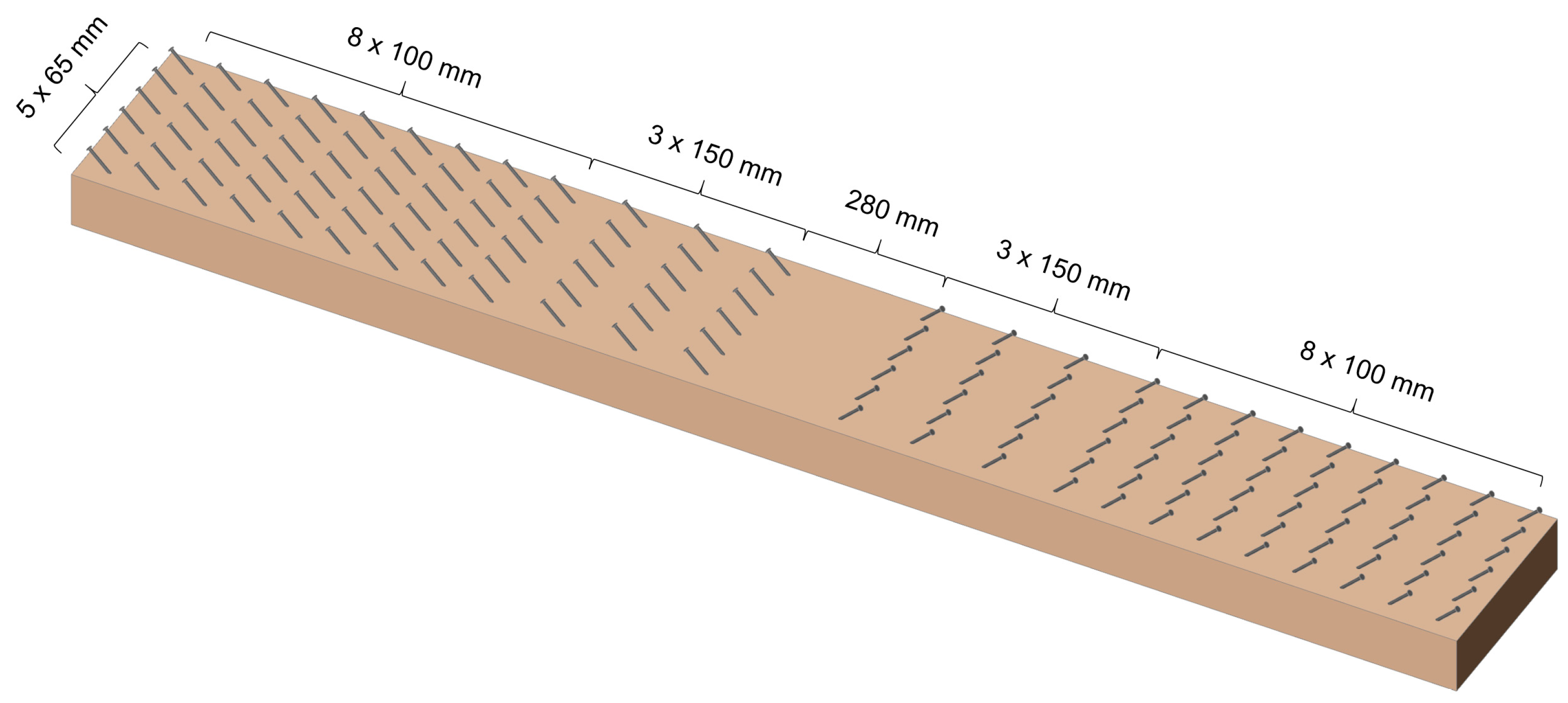
In the case of CLT panels with a 60 mm thick concrete slab, flat-head wood screws with a diameter of Ø8 mm and a length of 140 mm were used as shear connectors. The screws were installed in the CLT panels at a 45° angle, with a timber penetration of 80 mm. A total of 144 screws were used per panel. Their placement is shown in Figure 3. The primary purpose of using inclined screws is to ensure the transfer of shear flow at the concrete–timber interface. The anti-delamination effect of using these screws is limited due to the insufficient screw penetration into the middle (transverse) layer of the CLT panel, and the screws do not penetrate the bottom (longitudinal) layer at all. The number and layout of shear connectors were determined using a standard procedure according to Eurocode 5 [46] to ensure that shear connection failure would not occur during the experimental testing. The 45° screw angle was chosen to achieve the highest possible resistance and especially the stiffness of the composite CLT–concrete cross-section [47,48].
During the casting of the concrete slab, samples of concrete and reinforcement steel were taken for further laboratory testing of materials. Concrete cubes with dimensions 150 × 150 × 150 mm were properly measured, weighed, and subjected to destructive compressive testing. The average cube compressive strength of concrete at the time of testing the AC and BC series specimens was fcm,cube = 35.7 MPa. B500B concrete reinforcement was also used in the concrete composite slab, with four Ø8 mm reinforcement bars used in the longitudinal direction. According to the material tests preformation, the average yield strength of the reinforcement was fy = 560.0 MPa.

2.2. Test Set-Up and Loading Procedure

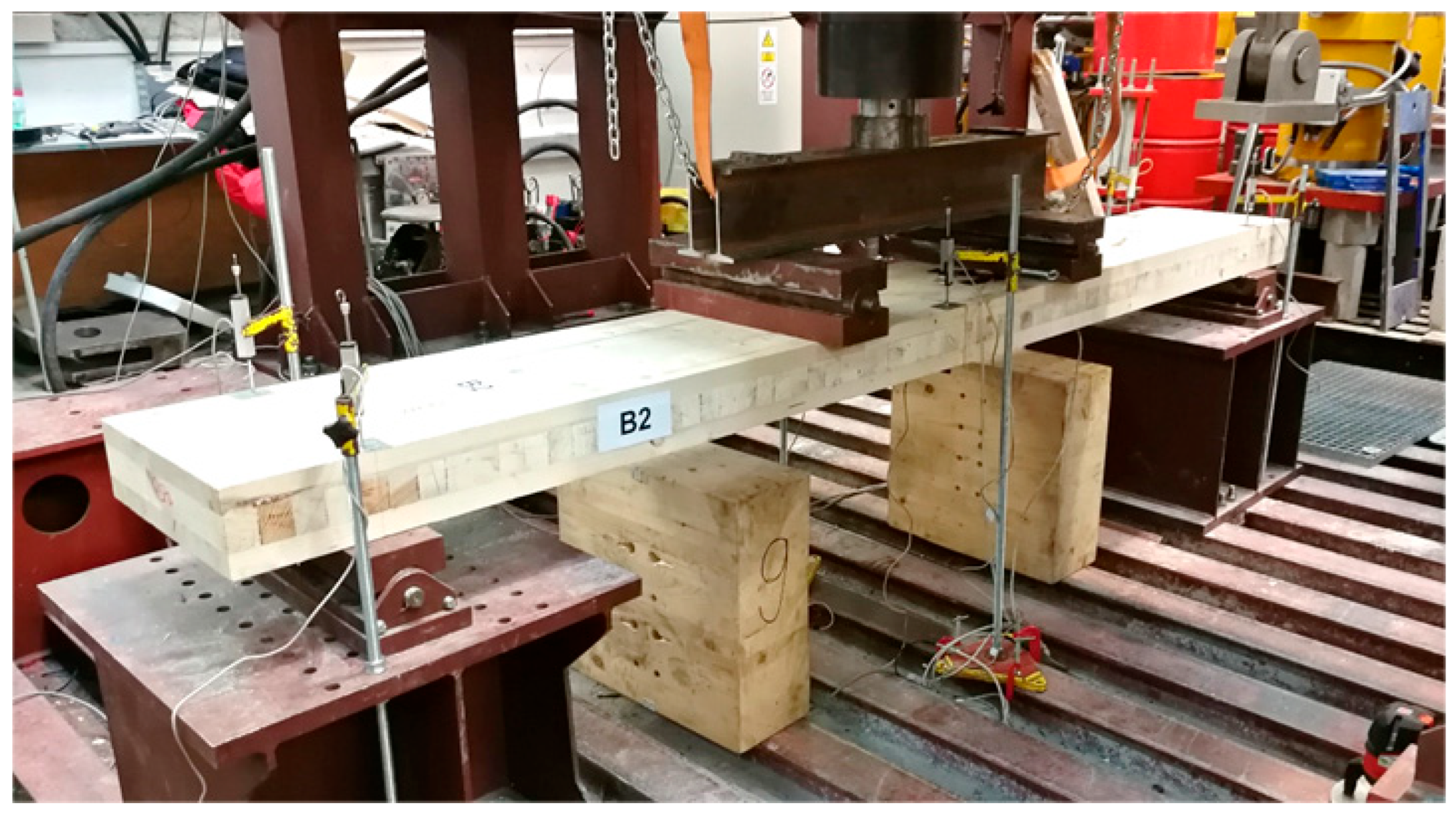
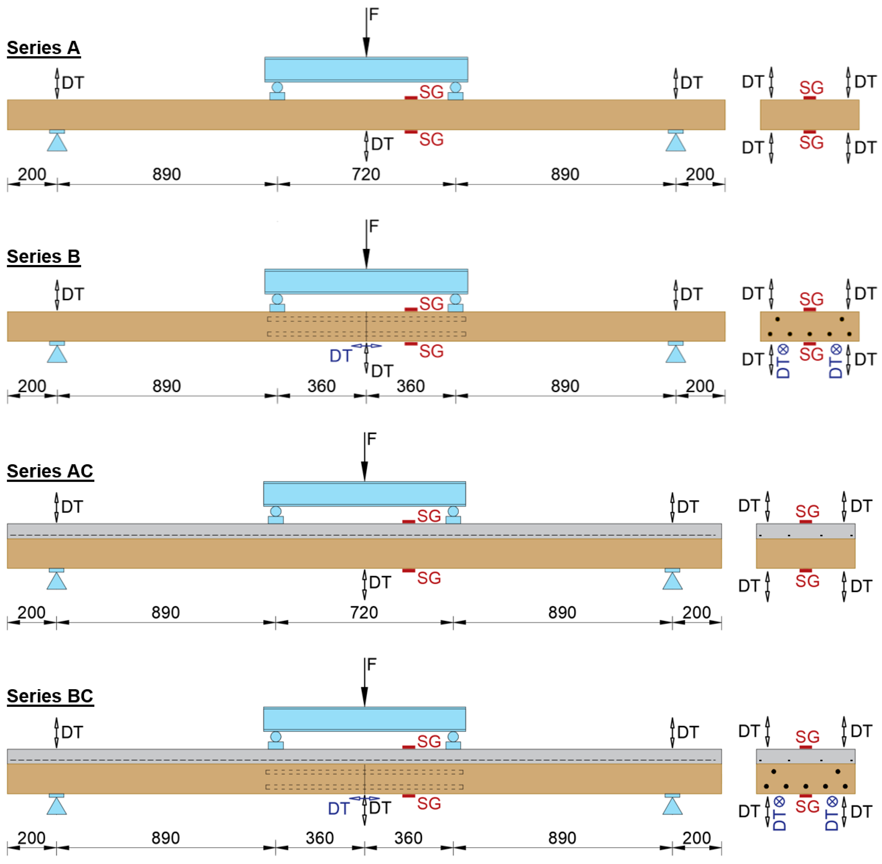
Individual specimens were tested in separate series. Each specimen was supported on a pair of steel bearings to ensure the most accurate static configuration of a simple supported beam with a span of 2.50 m. Two steel plates and rollers were placed on the upper surface of the specimens, on which a load-bearing crossbeam made of a pair of IPE 160 rolled profiles was placed. The specimens were thus subjected to four-point bending. A distribution plate with a modified hemispherical surface was placed at the mid-span on the upper surface of the crossbeam, against which the piston of the hydraulic cylinder rested during the test. The hydraulic cylinder, with a maximum capacity of 400 kN and its aggregate and electronic system, ensured controlled loading of the specimens by incremental deformation. The loading speed rate was 0.05 mm/s for all specimens. A photograph of the specimen under test is given in Figure 4. During the loading of the specimens, the load and its corresponding displacement were recorded for the specimens at the midpoint of the span and above the supports. In the case of selected specimens with joints, the opening of the joint-gap was also recorded. In addition to recording displacements, strains were also measured near the middle of the panel span, on both the upper and lower surfaces. Monitoring the strains was an important part of the experiment, primarily for the accurate control of the testing process and the prediction of the maximum load acting on the specimens. All displacement transducers and strain gauges, together with the output from the force sensor, were connected to a single data acquisition bus. The schematic arrangement of the test and the positions of the sensors for each series of tests are shown in Figure 5. The displacement transducers (marked as DS) record the vertical displacements and gap openings (in specimens with joints), while the strain gauges (labelled as SG) measure the strains on the top and bottom surfaces of the specimens.

3. Experimental Results

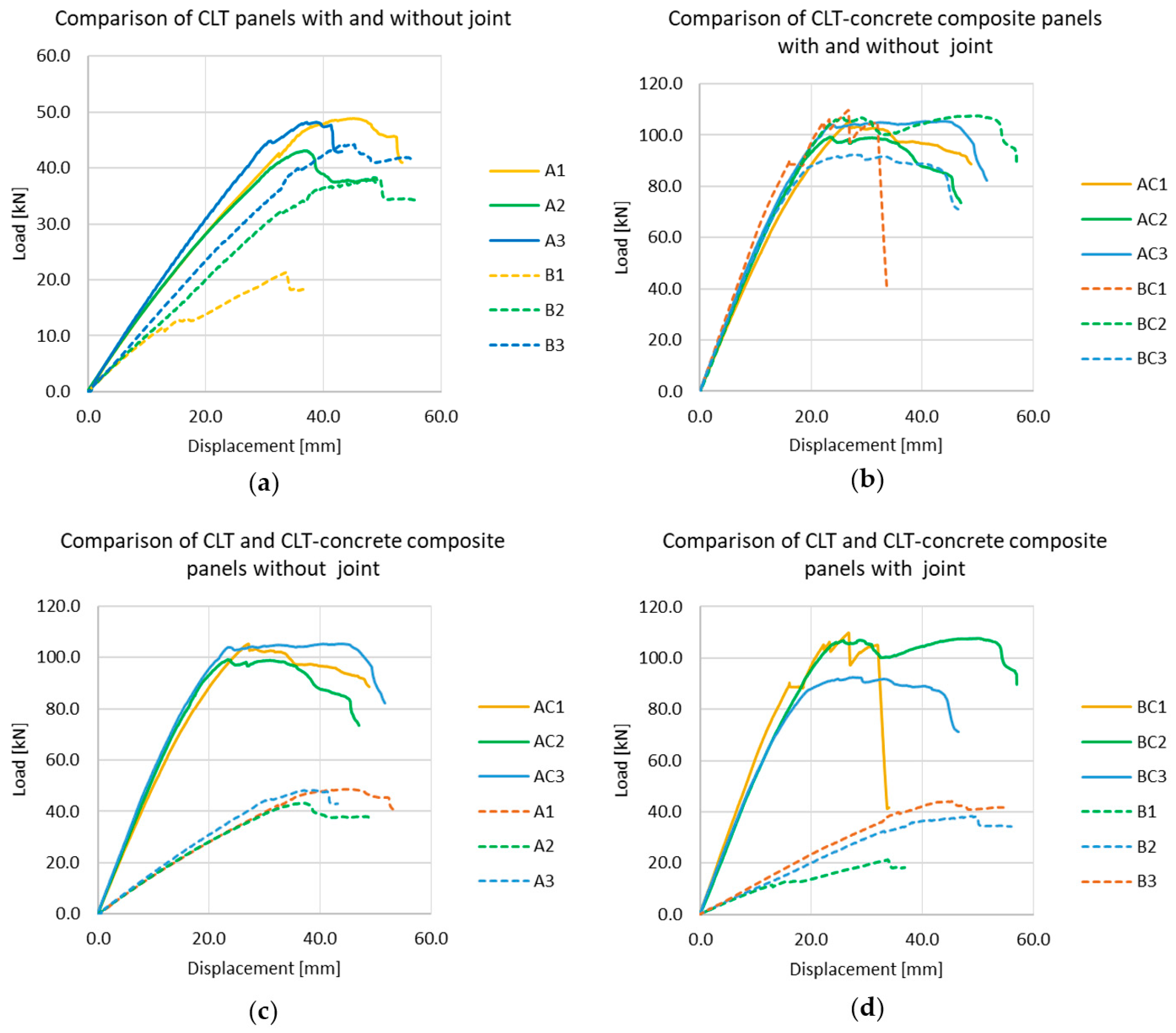
During the experimental programme, the applied load, strains on the surface, and displacements were recorded; for series B and BC, the opening of the joint-gap was also monitored, as described in Section 2. The experimental results are summarised in the figures below. The most important outcome is the set of load–displacement relationships, which—for clarity—are presented across multiple graphs in Figure 6. Based on the plots, the stiffness effect of individual specimens and significant differences in resistance between individual series (depending on structural design) are clearly visible.
In the case of specimens with a moment-resisting joint in the middle of their span, the joint-gap opening (s) was also recorded. Due to technical issues during the experimental testing of specimen B1, this piece of data (s) was not recorded for this specimen. For the purposes of this study, the missing values were reconstructed using second-degree polynomial regression with an interaction term. The model was calibrated on the complete datasets of specimens B2 and B3 (load F, mid-span displacement w, and joint-gap opening s) and then evaluated with the measured data of B1, consistent with its load–displacement curve. The regression model used to estimate the probable joint-gap opening was
Sgap = β0 + β1 · F2 · w + β3 · F2 + β4 · w2 + β5 · F · w
where
Sgap: reconstructed joint-gap opening (estimated from the regression model);
F: load;
W: mid-span displacement;
β0–β5: model coefficients determined by the least-squares method based on complex datasets of specimens B2 and B3.
The model was validated by comparing its outputs with the measured data of specimens B2 and B3 and achieved very good agreement (coefficient of determination R2 > 0.98). In all figures in this paper, the reconstructed (estimated) joint-gap opening data are clearly distinguished as B1* from the directly measured data. Figure 7 presents the load vs. joint-gap opening response, while Figure 8 illustrates the relationship between mid-span displacement and joint-gap opening.
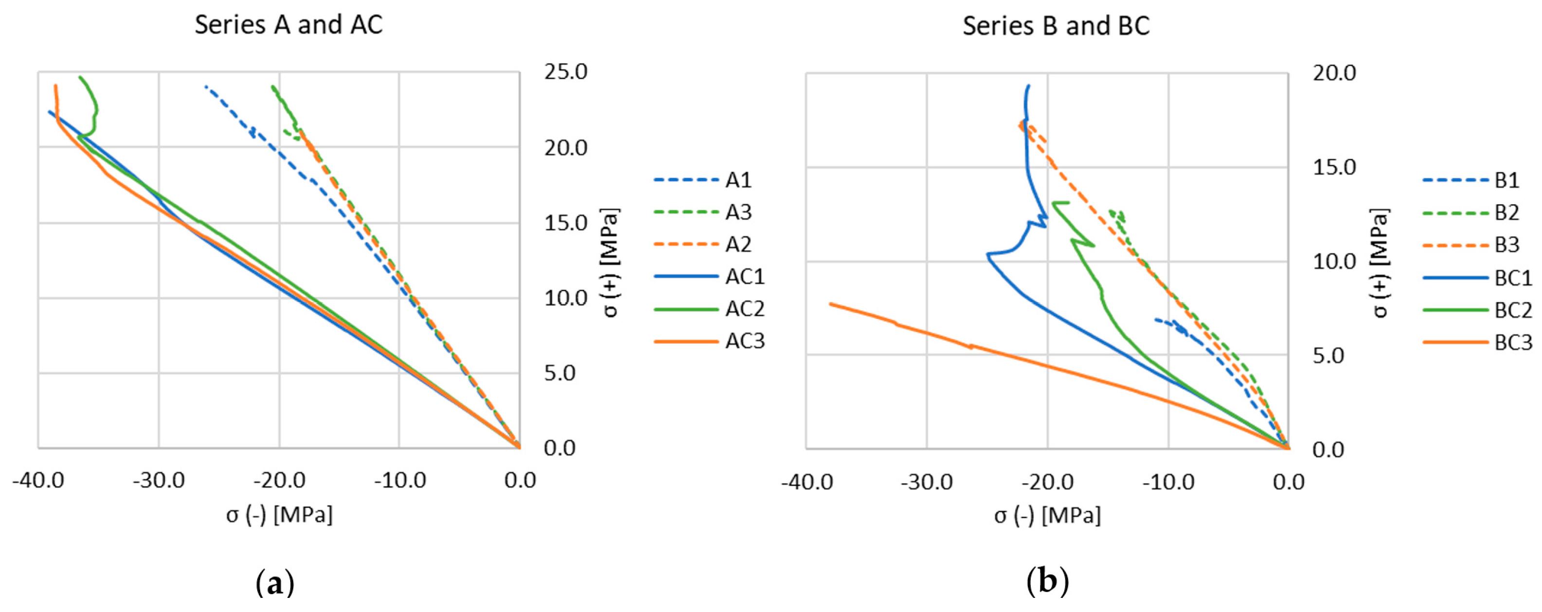
The outputs from the strain-gauge measurements (strains) were transformed into stress and, for better clarity, they are presented as surface stress on the top (compression, σ−) and bottom (tension, σ+) faces of the panels during the testing (Figure 9).
The curves were obtained by pairing synchronous σ− and σ+ readings throughout the test, so the trajectories directly reflect the relationship between the two surface stresses at the same load level. The primary purpose of the strain-gauge measurements was to indicate the stress levels during the experiments to enable proper test control.
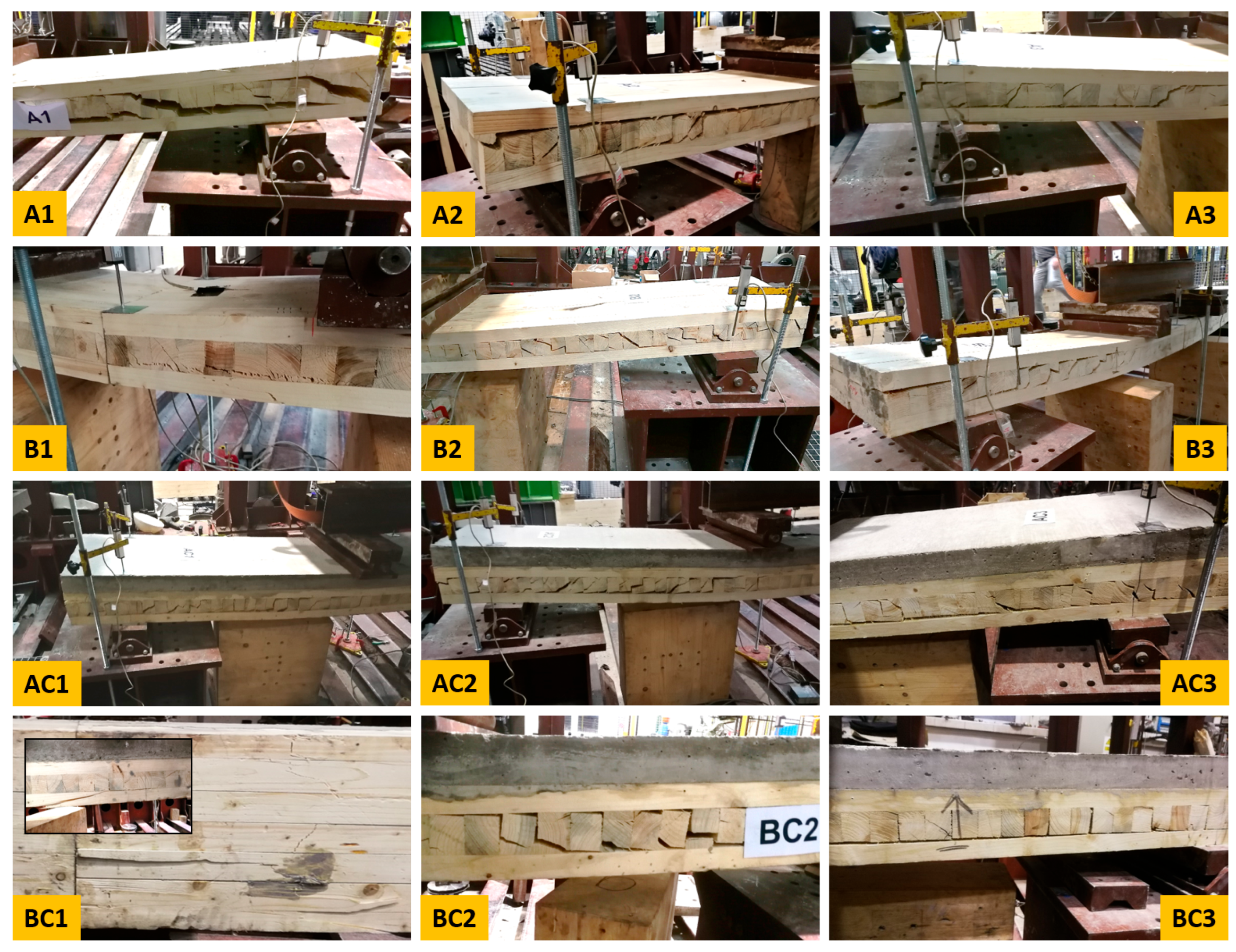
For each test, the failure mechanism of the specimen was documented. The specimens failed by rolling shear, delamination, joint failure, or a combination of flexural and joint failure. Table 1 summarises the ultimate load recorded during the test, the corresponding mid-span deflection, and the observed failure mode (documented in Figure 10).
It has been reaffirmed that rolling shear in the perpendicular layers of CLT panels is often a limiting factor in terms of the resistance of CLT panels subjected to out-of-plane loading [49,50,51]. This is related to the very low strength of wood under the shear stress acting on the radial–tangential plane perpendicular to the grain. The connection to the concrete slab appears to have no significant effect on this phenomenon.

4. Discussion

4.1. Observed Behaviour

The performed experimental measurements demonstrated a number of interesting dependencies related to both the action of the joint and its stiffness, as well as to the composite action between the CLT panel and the reinforced-concrete slab.
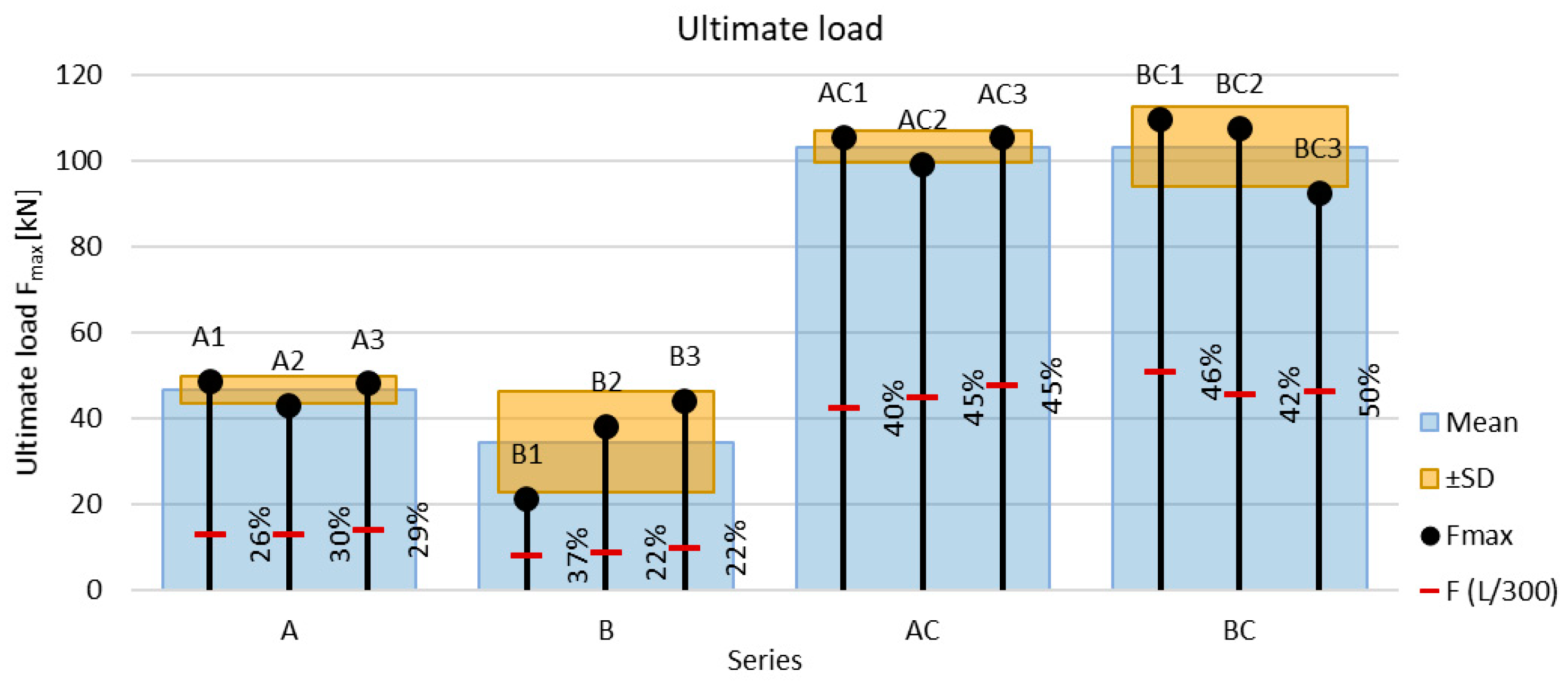
In each series, three specimens were tested, which represents the necessary minimum for a basic statistical assessment of the experimental programme. The ultimate load achieved during the test is analysed as the first and most important parameter. The graph in Figure 11 clearly presents the ultimate force value (Fmax) for each specimen, the average ultimate force value achieved within the individual series, as well as the standard deviation (SD).
In general, the series containing a moment-resisting joint exhibits a markedly higher SD, indicating greater variability in the ultimate load and failure mechanism. Since the failure modes included rolling shear, delamination, and joint failure (including flexural and joint failure combination), the larger SD indicates that some specimens with moment-resisting joints were probably close to joint failure. If there were no failure due to shear or due to delamination, probably even with a relatively small increase in the load, joint failure could occur.
In addition to the ultimate resistance of the system, a comparison from the point of view of limit deflections is also crucial. In the context of serviceability limit states, the limit value L/300, as specified in EN 1995 and its national annexe [46,52], is used as the criterion for deflection. The value of the load at the limit deflection level is shown in the graph in Figure 11 as a percentage of the ultimate load.
Another important investigated parameter is the determination of the initial stiffness and the comparison between individual specimens. Initial stiffness K0 was evaluated as the least-squares slope of the load–displacement (F-w) response within the linear range 10–40% of ultimate load (Fmax), following EN 408 [53] procedures for bending tests (and, by analogy, EN 26891 [54] for joints). For CLT panels, EN 16351 [55] refers to EN 408 for stiffness evaluation. The graph in Figure 12 documents the initial stiffness of individual specimens, the mean value within each series, and also the standard deviation.
In the case of CLT panels without a reinforced concrete slab (series A and B), the mean initial stiffness of the specimens with a joint is approximately 32% lower than that of the CLT panels without a joint. In the case of CLT panels with a reinforced concrete slab (series AC vs. BC), the average initial stiffness of the specimens with and without a joint is approximately the same (the difference is roughly at the level of the standard deviation).
The presence of the reinforced-concrete slab causes an average increase in initial stiffness of more than ~3.5 times for CLT panels without a joint and more than ~5.5 times for CLT panels with a joint.
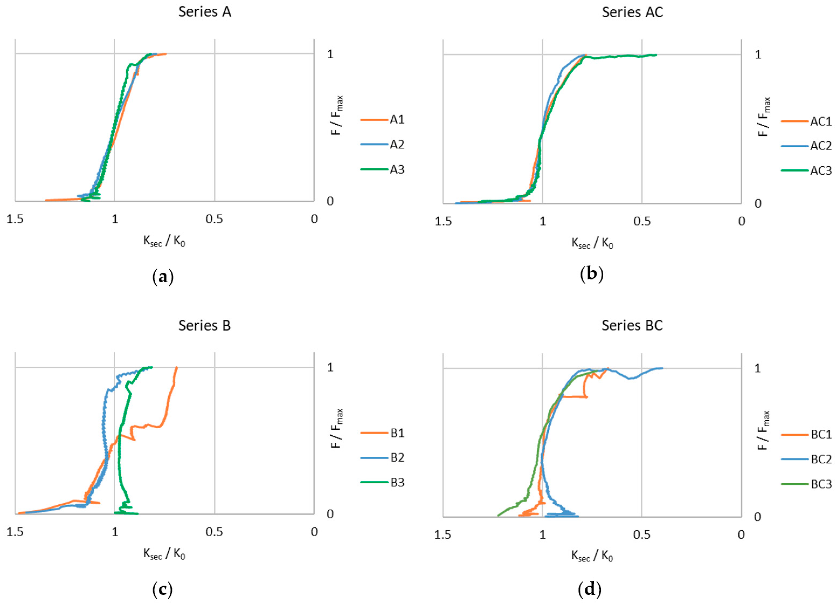
Another view of the stiffness of individual CLT panels is provided in Figure 13, which shows the normalised stiffness Ksec/K0 versus the normalised load F/Fmax. For specimens with a joint (series B and series BC), significant differences in the development of Ksec/K0 can be clearly observed between specimens within the same series, indicating considerable inter-specimen variability in the shape of the curves. In contrast, for the series without a joint (series A and AC), the inter-specimen variability is relatively small.
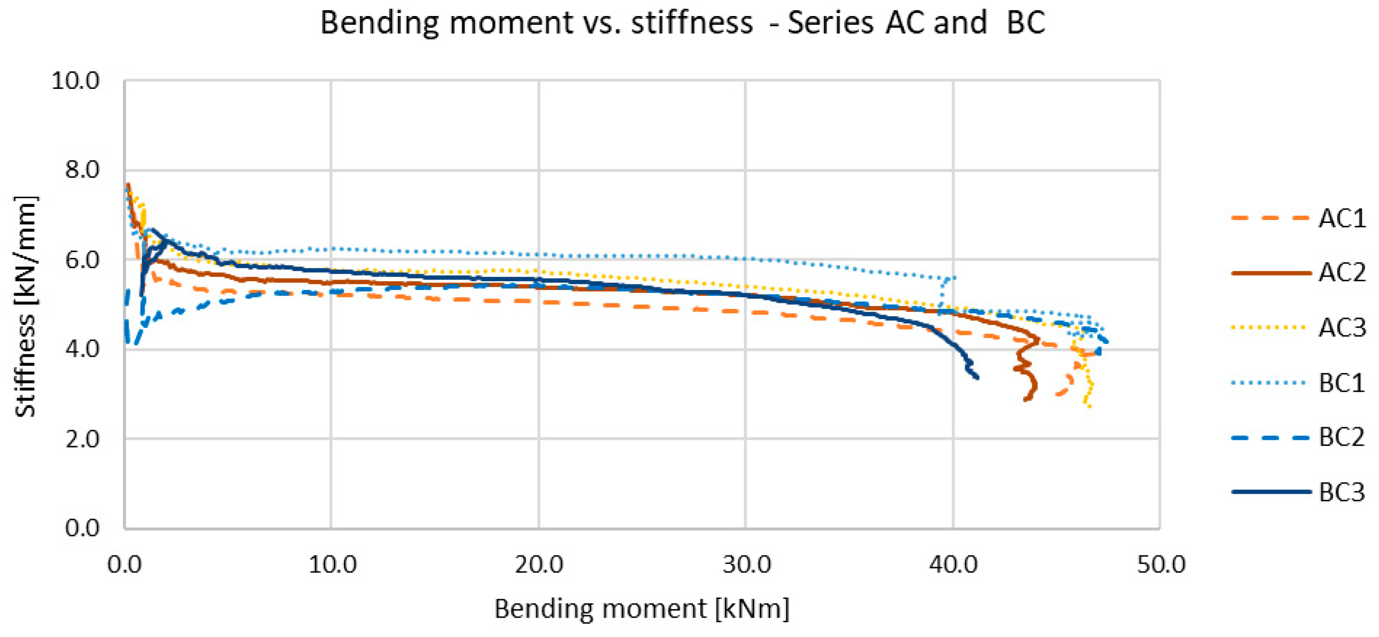
For completeness, Figure 14 and Figure 15 illustrate the gradual decrease in stiffness of the specimens from series A and B as well as series AC and BC, as a function of the increasing bending moment at midspan (M = (F/2 · a)). Pronounced differences in stiffness and its reduction are again particularly evident between specimens of series A and B.
Based on the normalised stiffness graphs (Ksec/K0F/Fmax) and the relationship between bending moment and secant stiffness (MKsec), the global stiffness was transformed into the apparent bending stiffness EIapp. As the deflection w is proportional to the ratio F/EI, for a given test arrangement geometry (L—distance between supports; a—distance from the support to the point of load application), the following expression can be written:
E I a p p = Δ g e o m ( L ; a ) F w ( F ) = Δ g e o m K s e c ( F )
where
EIapp: apparent bending stiffness;
Δgeom: geometric coefficient taking into account the position of the load and the boundary conditions;
F: load;
w: displacement;
Ksec: secant stiffness.
From the above, the specific EIapp for a specimen subjected to four-point bending can be determined, assuming the applied load F and displacement w are known, as follows:
E I a p p = F a ( 3 L 2 4 a 2 ) 48 w
EIapp includes not only the standard bending stiffness of the cross-section but also all system compliances (shear deformations of the CLT panel, slip at the CLT–concrete interface, joint behaviour, etc.). The EIapp values were subsequently compared directly with the joint-gap opening—see Figure 16 (note: the joint-gap opening of specimen B1, designated as B1*, was estimated using a regression model; see Section 3). For the specimens with a composite reinforced-concrete slab, a more significant decrease in EIapp stiffness can be observed with increasing joint-gap opening (s).
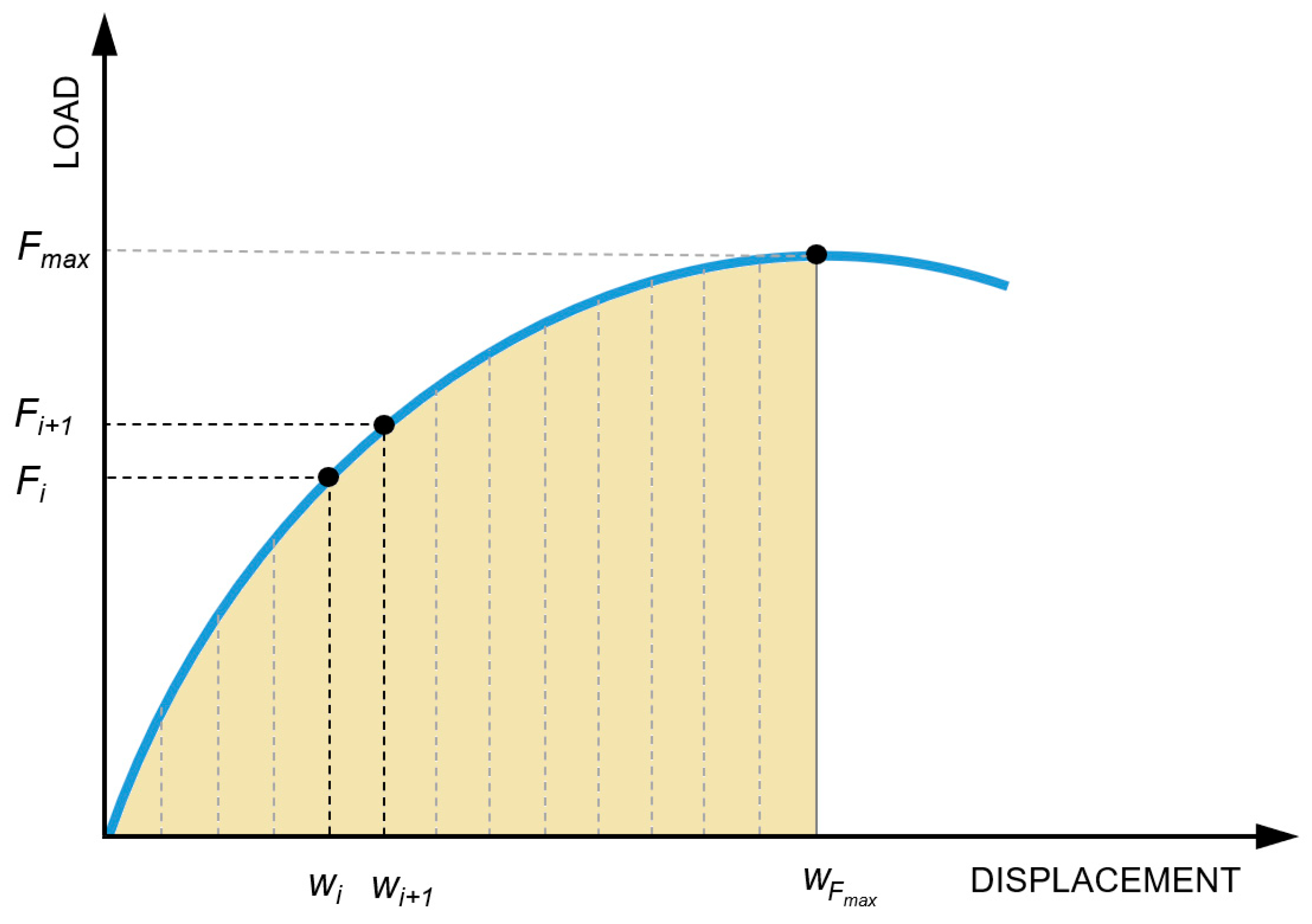
For a comprehensive assessment of the actual behaviour of the investigated specimens, it is not entirely sufficient to evaluate only the load capacity and stiffness of the system. A suitable integrated indicator is the energy U, i.e., the work performed by the load during the deformation of the specimen. While the dependencies Ksec/K0F/Fmax; MKsec; and EIapps (joint-gap opening) describe the changes in the stiffness of the element and the mechanical behaviour of the joint, the energy provides another comparable metric across the series of specimens and summarises the total work of the system (in this case, until Fmax is reached). This allows for a comparison of the usable deformation capacity and the total toughness of the system. The energy was determined as the area under the load–displacement curve (see Figure 17) for each specimen:
U = F d w 1 2 F i + 1 + F i w i + 1 w i
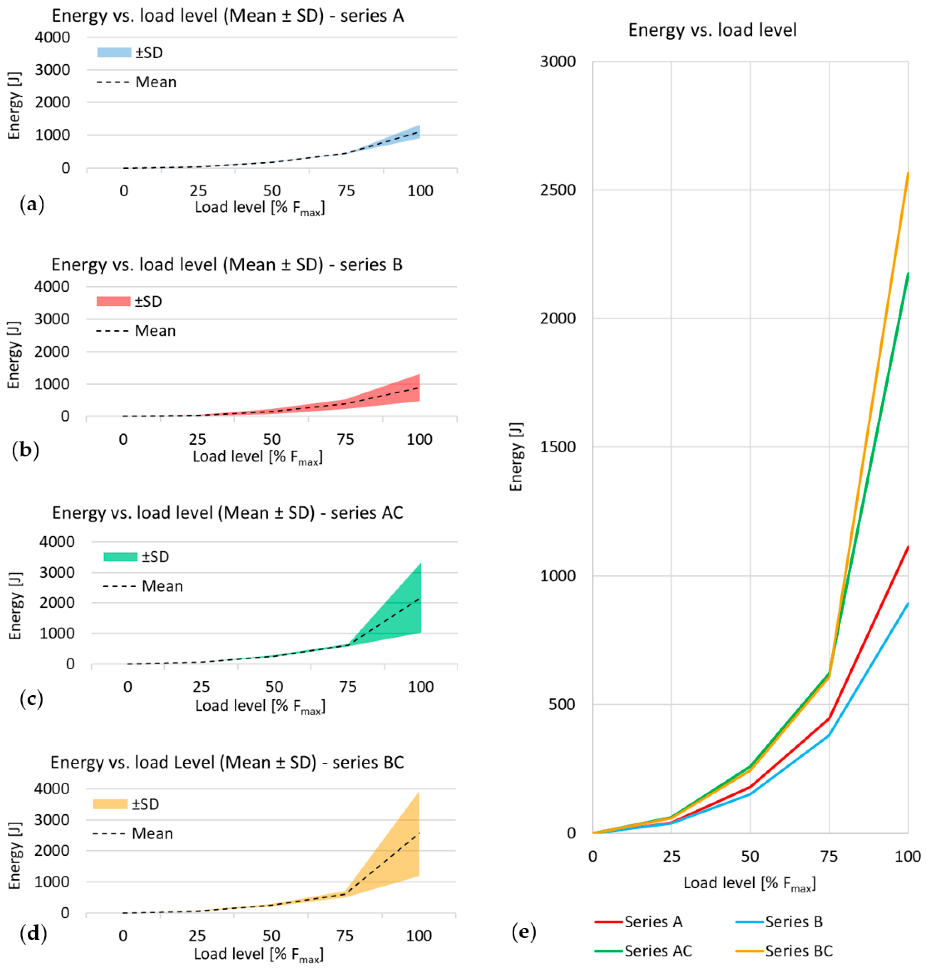
The calculations were performed by interpolating the load–displacement data at the target load levels {0, 25, 50, 75, 100% Fmax} for each specimen and subsequently computing the partial increments of ΔU over the corresponding intervals. The graphs in Figure 18 present the cumulative energy as a function of load level for each series. In graphs (a–d), the average value of the series is shown, along with the standard deviation, indicated by a coloured bar (±SD; n = 3). Plot (e) compares the energy increment between series. The bar chart in Figure 19 shows the energy increment within individual quartiles, as well as the total energy for each specimen.
The first two energy increments (ΔU0→25% Fmax; ΔU25→50% Fmax) primarily encompass the elastic phase of loading of the specimens. The subsequent intervals (ΔU50→75% Fmax; ΔU75→100% Fmax) already encompass the post-elastic phase under loading and the associated nonlinear redistribution of internal forces in the specimen during the test. For all specimens, the largest increment occurs in the final interval ΔU75→100% Fmax, which is also reflected by the sharp rise in the curves in Figure 18. As the load level increases, the magnitude of the standard deviation grows markedly.

4.2. Possible Concept of a Theoretical Model of the Joint

Experimental testing has demonstrated the actual behaviour of the moment-resisting, embedded joint of CLT panels from several aspects. The obtained measurements provide a solid basis for the successful application of the proposed solution in practice, particularly when used as part of CLT–concrete composite panels. However, for the practical design of the connection, it is first necessary to at least indicate the concept of a theoretical (mechanical) model, which will be addressed systematically in future analyses. Based on the premise that common, practical, engineering calculations of simple structural elements should not be primarily based on complex nonlinear numerical models (typically created in research-and-development software such as ANSYS, ABAQUS, ADINA, etc.), at this stage, a concept based on the generally known and widely used component method appears to be more suitable. The component method began to be applied in the 1970s and 1980s, initially on bolted moment-resisting joints of steel structures [56,57]. Later, it was elaborated in detail and became part of Eurocode 3—EN 1993-1-8 [58], where the component method is presented as a separate design framework. The method has also become part of the theory of connections of timber structures and is commonly used in it for the theoretical description of the actual action of connections [59,60,61]. The method utilises the decomposition of connections (joints) into basic components (compression, tension, and shear), which have their own defined stiffness, resistance, and deformation capacity. In the case we studied, a single type of connection is analysed (see Figure 1), which is, however, used in two different types of structures (ceiling slabs consisting only of CLT panels and CLT–concrete composite slabs). Figure 20 documents the concept of a joint defined using the component method and loaded with a bending moment, both in the case of separate CLT panels (a) and in the case of CLT panels coupled to a reinforced-concrete slab (b, c).
In the case of CLT–concrete composite slabs, the situation is more complicated, since the CLT panel is divided and the reinforced-concrete slab is solid. In addition to determining the stiffness of the connection between the CLT panel and the reinforced-concrete slab (component characterised by stiffness coefficient kSC), the position of the neutral axis of the composite cross-section must be evaluated. The degree of composite action (kSC) influences the neutral-axis position via the effective stiffness but does not determine it directly. In case the neutral axis lies in a reinforced-concrete slab (standard case), the entire CLT panel is stressed in tension, the compression is transmitted only by the reinforced-concrete slab, and the model uses only the stiffness coefficient kRT in this area (representing the action of glued-in steel rods in tension). If the neutral axis falls within the CLT, the timber compression component (characterised by stiffness coefficient kTC) becomes active in the upper part of the CLT; the lower row of glued-in rods is in tension (kRT), while the upper row may be in tension (kRT) or in compression (kRC), depending on the neutral axis position. Further research is needed for the experimental determination of the individual components, especially for the determination of kRT and kRC (predominantly bilinear behaviour [60,62,63]), which are significantly influenced not only by the materials used (steel, adhesive, timber) but also by the position of the glued-in rod within the individual layers of the panel (transverse/longitudinal lamellae) [35]. It will also be necessary to pay attention to the stiffness coefficient kTC, which describes the behaviour of the contact between timber elements parallel to the grain, where predominantly nonlinear behaviour is assumed [64,65,66].

5. Conclusions

The presented experimental research of the embedded moment-resisting joint of CLT panels with glued-in high-strength steel rods demonstrated sufficient resistance and stiffness of the designed solution.
In the case of simple CLT panels without a reinforced-concrete slab, the joint resistance is approximately 74% of their rolling shear/delamination capacity (pure bending failure of the CLT panels without joint did not occur in any case). The only specimen that significantly reduced the mean resistance of series B (CLT panels with a joint) was B1—it failed due to joint failure. This reduction in resistance can probably be associated with the potentially imperfect joint execution and/or defects in the timber (or in the CLT panel execution) near the joint. When comparing the initial stiffness K0, the stiffness of the specimens with the joint reaches approximately 68% of the initial stiffness of the whole CLT panel.
Another important part of this research was the implementation of composite action between the CLT panels and a reinforced-concrete slab, as well as its combination with the moment-resisting joint. The experimental results generally demonstrate the high efficiency of the composite action and its effect on increasing the resistance and stiffness of the tested structural members. For CLT–concrete composite panels without a joint, the ultimate load Fmax increased, on average, by 121%; for specimens with the joint, the resistance increased by up to 198%. When comparing loads at the serviceability limit deflection L/300 (i.e., 8.33 mm), the increase in load FL/300 due to composite action was up to 242% for specimens without a joint and 442% for specimens with the joint.
In the case of CLT–concrete composite panels, the moment-resisting joint does not significantly limit the resistance of the structural member (because the governing failure mode is again predominantly rolling shear or delamination). The essential finding is that the stiffness of CLT–concrete composite panels with a joint is practically identical to the CLT–concrete composite panels without a joint. The only specimen that failed due to bending stress of the element (in combination with joint failure) was BC1, which also reached the highest ultimate load value, Fmax = 109.71 kN, among all experimentally tested specimens. Based on the relatively low value of the standard deviation within the series, it is possible to predict that if specimens BC2 and BC3 had not failed in rolling shear/delamination, failure would have occurred due to a combination of bending and joint failure, even with a relatively small increase in load.
Based on the assessment of the energy required to achieve ultimate load Fmax, it is also necessary to point out the sufficient toughness demonstrated by the specimens with the joint compared to the whole CLT panels.
From a practical point of view, it is also necessary to highlight potential risks in joint fabrication based on experience from specimen production. These are primarily related to the joint geometry (maintaining the correct spacing and perpendicularity of the holes, proper alignment of the connected CLT panels), which can be ensured by precise machining and drilling. A second potential risk lies in the correct selection and application of the adhesive—appropriate viscosity must be ensured, together with proper (complete) injection into the holes.
From the perspective of further research, it will be necessary to focus primarily on developing a detailed theoretical model based on the component method and on analysing practical design procedures for this type of joint.

Author Contributions

Conceptualization, M.F.; methodology, M.F. and J.G.; software, M.F.; validation, J.G., P.K. and M.F.; formal analysis, J.G.; investigation, M.F. and J.G.; resources, P.K.; data curation, J.G.; writing—original draft preparation, M.F.; writing—review and editing, J.G.; visualisation, J.G.; supervision, P.K.; project administration, M.F.; funding acquisition, P.K. All authors have read and agreed to the published version of the manuscript.

Funding

This research is supported by the Slovak Research and Development Agency under contract No. APVV-23-0626 and by Research Project No. 1/0321/24 of the Slovak Grant Agency.

Data Availability Statement

The data presented in this study are available on reasonable request from the corresponding author.

Acknowledgments

The material for the specimens was provided by Femada, Ltd.

Conflicts of Interest

The authors declare no conflicts of interest.

References

  1. Schickhofer, G. Starrer und Nachgiebiger Verbund bei Geschichteten, Flächenhaften Holzstrukturen; Graz University of Technology: Graz, Austria, 2013; ISBN 978-3-85125-268-2. [Google Scholar]
  2. 100 Projects UK CLT. Produced by Waugh Thistleton Architects on behalf of the Softwood Lumber Board & Forestry Innovation Investment. Printed in Canada, 2018. Available online: https://waughthistleton.com/100-projects-uk-clt/ (accessed on 28 September 2025).
  3. Swedish Wood. The CLT Handbook. CLT Structures—Facts and Planning. Stockholm, May 2019. Available online: https://www.swedishwood.com/publications/list_of_swedish_woods_publications/the-clt-handbook/ (accessed on 28 September 2025).
  4. Karacabeyli, E.; Gagnon, S. Eds. Canadian CLT Handbook. 2019. Available online: https://web.fpinnovations.ca/clt/ (accessed on 28 September 2025).
  5. Kremer, P.D.; Guiver, J. Mass Timber Construction in Australia and New Zealand–Status, and Economic and Environmental Influences on Adoption. Wood Fiber Sci. 2018, 50, 128–138. [Google Scholar] [CrossRef]
  6. Abed, J.; Rayburg, S.; Rodwell, J.; Neave, M. A Review of the Performance and Benefits of Mass Timber as an Alternative to Concrete and Steel for Improving the Sustainability of Structures. Sustainability 2022, 14, 5570. [Google Scholar] [CrossRef]
  7. Structural Timber Association, Technical Bulletin 01—Timber as a Structural Material—An Introduction. Available online: https://www.structuraltimber.co.uk/ (accessed on 31 July 2025).
  8. Harte, A.M. Mass Timber–the Emergence of a Modern Construction Material. J. Struct. Integr. Maint. 2017, 2, 121–132. [Google Scholar] [CrossRef]
  9. Ibn-Mohammed, T.; Greenough, R.; Taylor, S.; Ozawa-Meida, L.; Acquaye, A. Operational vs. embodied emissions in buildings—A review of current trends. Energy Build. 2013, 66, 232–245. [Google Scholar] [CrossRef]
  10. Taylor, A.; Gu, H.; Nepal, P.; Bergman, R. Carbon Credits for Mass Timber Construction. Bioprod. Bus. 2023, 8, 1–12. [Google Scholar] [CrossRef]
  11. Andersen, J.H.; Rasmussen, N.L.; Ryberg, M.W. Comparative life cycle assessment of cross-laminated timber building and concrete building with special focus on biogenic carbon. Energy Build. 2022, 254, 111604. [Google Scholar] [CrossRef]
  12. Chen, C.X.; Pierobon, F.; Jones, S.; Maples, I.; Gong, Y.; Ganguly, I. Comparative life cycle assessment of mass timber and concrete residential buildings: A case study in China. Sustainability 2022, 14, 144. [Google Scholar] [CrossRef]
  13. Pierobon, F.; Huang, M.; Simonen, K.; Ganguly, I. Environmental benefits of using hybrid CLT structure in mid-rise non-residential construction: An LCA-based comparative case study in the U.S. Pacific Northwest. J. Build. Eng. 2019, 26, 100862. [Google Scholar] [CrossRef]
  14. EN 15804:2012+A2:2019; Sustainability of Construction Works—Environmental Product Declarations—Core Rules for the Product Category of Construction Products. European Committee for Standardization, CEN: Brussels, Belgium, 2019.
  15. EN 15978:2011; Sustainability of Construction Works—Assessment of Environmental Performance of Buildings—Calculation Method. European Committee for Standardization, CEN: Brussels, Belgium, 2011.
  16. ASTM E2921–22; Standard Practice for Minimum Criteria for Comparing Whole Building Life Cycle Assessments for Use with Building Codes, Standards, and Rating Systems. ASTM International: West Conshohocken, PA, USA, 2023.
  17. ISO 14044:2006; Environmental Management—Life Cycle Assessment—Requirements and Guidelines. International Organization for Standardization: Geneva, Switzerland, 2006.
  18. ISO 21930:2017; Sustainability in Buildings and Civil Engineering Works—Core Rules for Environmental Product Declarations of Construction Products and Services. International Organization for Standardization: Geneva, Switzerland, 2017.
  19. Wallner-Novak, M.; Koppelhuber, J.; Pock, K. Cross-Laminated Timber Structural Design—Basic Design and Engineering Principles According to Eurocode, 1st ed.; Working group of the Austrian timber industry for promotion of the application of timber; proHolz: Vienna, Austria, 2014; ISBN 978-3-902926-03-6. [Google Scholar]
  20. Stieb, T.; Maderebner, R.; Dietsch, P. A Timber–Concrete–Composite Edge Connection for Two-Way Spanning Cross-Laminated Timber Slabs—Experimental Investigations and Analytical Approach. Buildings 2023, 13, 3004. [Google Scholar] [CrossRef]
  21. Hosseini, A.; Shahnewaz, M.; Zhou, J.; Tannert, T. Structural performance of CLT moment connections in the minor strength axis. Eng. Struct. 2025, 328, 119788. [Google Scholar] [CrossRef]
  22. Ganjali, H.; Pace, A.; Tannert, T. Structural performance of adhesively bonded and hybrid screw-adhesive CLT panel-to-panel floor joints. Constr. Build. Mater. 2025, 475, 141139. [Google Scholar] [CrossRef]
  23. Lal, R.; Hashemi, A.; Quenneville, P. An innovative connection system for platform-type mass timber buildings. Resilient Cities Struct. 2025, 4, 14–29. [Google Scholar] [CrossRef]
  24. Piazza, M. Optimization Process in the Use of Wood and Wood-Based Materials in Hybrid and Composite Structures. In WCTE 2016 e-Book: Containing all Full Papers Submitted to the World Conference on Timber Engineering (WCTE 2016), Vienna, Austria, 22–25 August 2016; TU Verlag Wien: Vienna, Austria, 2016. [Google Scholar]
  25. Bajzecerová, V. Bending Stiffness of CLT-Concrete Composite Members—Comparison of Simplified Calculation Methods. Procedia Eng. 2017, 190, 15–20. [Google Scholar] [CrossRef]
  26. Bajzecerová, V.; Kanócz, J.; Rovňák, M.; Kováč, M. Prestressed CLT-concrete composite panels with adhesive shear connection. J. Build. Eng. 2022, 56, 104785. [Google Scholar] [CrossRef]
  27. Pang, S.J.; Ahn, K.S.; Jeong, S.M.; Lee, G.C.; Kim, H.S.; Oh, J.K. Prediction of bending performance for a separable CLT-concrete composite slab connected by notch connectors. J. Build. Eng. 2022, 49, 103900. [Google Scholar] [CrossRef]
  28. Zhao, X.; Zhang, B.; Kilpatrick, T.; Sanderson, I. Numerical Analysis on Global Serviceability Behaviours of Tall CLT Buildings to the Eurocodes and UK National Annexes. Buildings 2021, 11, 124. [Google Scholar] [CrossRef]
  29. Van de Lindt, J.; Amini, M.O.; Rammer, D.; Line, P.; Pei, S.; Popovski, M. Determination of Seismic Performance Factors for Cross-Laminated Timber Shear Walls Based on FEMA P695 Methodology; General Technical Report FPL-GTR-281; U. S. Department of Agriculture, Forest Service, Forest Products Laboratory: Madison, WI, USA, 2023; p. 515.
  30. Perković, N.; Skejić, D.; Rajčić, V. Numerical Analysis of Fire Resistance in Cross-Laminated Timber (CLT) Constructions Using CFD: Implications for Structural Integrity and Fire Protection. Forests 2024, 15, 2046. [Google Scholar] [CrossRef]
  31. Dúbravská, K.; Tereňová, Ľ.; Štefková, J. CLT Construction Performance Under Thermal Loading. Wood Res. 2020, 65, 605–614. [Google Scholar] [CrossRef]
  32. Xing, Z.; Zhang, J.; Aslani, F. CLT two-way slabs fire resistance test; numerical simulation analysis. J. Build. Eng. 2025, 105, 112529. [Google Scholar] [CrossRef]
  33. Di Bella, A.; Mitrovic, M. Acoustic Characteristics of Cross-Laminated Timber Systems. Sustainability 2020, 12, 5612. [Google Scholar] [CrossRef]
  34. Schenk, M.; Ohm, J.; Winter, S. Eurocode5: From Mandate to Second Generation—Review, Insight and Outlook. In Proceedings of the 14th World Conference on Timber Engineering 2025 (WCTE 2025), Brisbane, Australia, 22–26 June 2025; pp. 36–45. [Google Scholar] [CrossRef]
  35. Onishi, S.; Karube, Y.; Nasu, H. Study on Control Wooden Joint Rigidity, Strength and Ductility with Combinations of Wooden Fibre Directions. In WCTE 2016 e-Book: Containing all Full Papers Submitted to the World Conference on Timber Engineering (WCTE 2016), Vienna, Austria, 22–25 August 2016; TU Verlag Wien: Vienna, Austria, 2016; Available online: https://repositum.tuwien.at/handle/20.500.12708/172 (accessed on 28 September 2025).
  36. Joyce, T.; Ballerini, M.; Smith, I. Mechanical behaviour of in-plane shear connections between CLT wall panels. In Proceedings of the CIB Working Commission W18–Timber Structures. 44th Meeting, Alghero, Italy, 29 August–1 September 2011; Available online: https://www.researchgate.net/publication/267244948 (accessed on 28 September 2025).
  37. Hossain, A.; Danzig, I.; Tannert, T. Cross-laminated timber shear connections with double-angled self-tapping screw assemblies. J. Struct. Eng. 2016, 142, 04016099. [Google Scholar] [CrossRef]
  38. Subhani, M.; Shill, S.K.; Al-Deen, S.; Anwar-Us-Saadat, M.; Ashraf, M. Flexural Performance of Splice Connections in Cross-Laminated Timber. Buildings 2022, 12, 1124. [Google Scholar] [CrossRef]
  39. Sadeghi, M.; Ballerini, M.; Smith, I.; Pedrotti, E. Bending properties of connections in cross laminated timber. In Proceedings of the IABSE Conference: Elegance in Structures, Nara, Japan, 13–15 May 2015; pp. 366–367. [Google Scholar] [CrossRef]
  40. Asselstine, J.; Lam, F.; Zhang, C. New edge connection technology for cross laminated timber (CLT) floor slabs promoting two-way action. Eng. Struct. 2021, 233, 111777. [Google Scholar] [CrossRef]
  41. Tlustochowicz, G.; Serrano, E.; Steiger, R. State-of-the-art review on timber connections with glued-in steel rods. Mater. Struct. 2011, 44, 997–1020. [Google Scholar] [CrossRef]
  42. Ayansola, G.S.; Tannert, T.; Vallee, T. Experimental investigations of glued-in rod connections in CLT. Constr. Build. Mater. 2022, 324, 126680. [Google Scholar] [CrossRef]
  43. Shirmohammadli, Y.; Hashemi, A.; Masoudnia, R.; Quenneville, P. Experimental and numerical investigation of cross-laminated timber joints with multiple glued-in rods. In Proceedings of the World Conference on Timber Engineering (WCTE 2023), Oslo, Norway, 19–22 June 2023; pp. 1389–1396. [Google Scholar] [CrossRef]
  44. Ayansola, G.S.; Tannert, T.; Vallee, T. Glued-in multiple steel rod connections in cross-laminated timber. J. Adhes. 2021, 98, 810–826. [Google Scholar] [CrossRef]
  45. Azinović, B.; Danielsson, H.; Serrano, E.; Kramar, M. Glued-in rods in cross laminated timber—Numerical simulations and parametric studies. Constr. Build. Mater. 2019, 212, 431–441. [Google Scholar] [CrossRef]
  46. EN 1995-1-1:2004+A2:2014; Eurocode 5: Design of Timber Structures—Part 1-1: General—Common Rules and Rules for Buildings. European Committee for Standardization, CEN: Brussels, Belgium, 2014.
  47. Esmaeildoust, S.; Tomlinson, D.; Chui, Y.H. Performance of Timber-Concrete Composite (TCC) Systems Connected with Inclined Screws: A Literature Review. J. Compos. Sci. 2025, 9, 13. [Google Scholar] [CrossRef]
  48. Du, H.; Hu, X.; Xie, Z.; Wang, H. Study on shear behavior of inclined cross lag screws for glulam-concrete composite beams. Constr. Build. Mater. 2019, 224, 132–143. [Google Scholar] [CrossRef]
  49. Li, M. Evaluating rolling shear strength properties of cross-laminated timber by short-span bending tests and modified planar shear tests. J. Wood Sci. 2017, 63, 331–337. [Google Scholar] [CrossRef]
  50. Li, X.; Ashraf, M.; Subhani, M.; Kremer, P.; Li, H.; Anwar-Us-Saadat, M. Rolling shear properties of cross-laminated timber (CLT) made from Australian Radiata Pine–An experimental study. Structures 2021, 33, 423–432. [Google Scholar] [CrossRef]
  51. Sandoli, A.; Calderoni, B. The rolling shear influence on the out-of-plane behavior of CLT panels: A comparative analysis. Buildings 2020, 10, 42. [Google Scholar] [CrossRef]
  52. STN EN 1995-1-1/NA:2019-12; National Annex to EN 1995-1-1:2004+A2:2014 Eurocode 5: Design of Timber Structures—Part 1-1: General—Common Rules and Rules for Buildings. ÚNMS SR: Bratislava, Slovakia, 2019.
  53. EN 408:2010+A1:2012; Timber Structures—Structural Timber and Glued Laminated Timber—Determination of Some Physical and Mechanical Properties. European Committee for Standardization, CEN: Brussels, Belgium, 2012.
  54. EN 26891:1991; Timber Structures—Joints Made with Mechanical Fasteners—General Principles for the Determination of Strength and Deformation Characteristics. European Committee for Standardization, CEN: Brussels, Belgium, 1991.
  55. EN 16351:2021; Timber Structures—Cross Laminated Timber—Requirements. European Committee for Standardization: Brussels, Belgium, 2021.
  56. Zoetemeijer, P. A Design Method for the Tension Side of Statically Loaded, Bolted Beam-to-Column Connections. Heron 1974, 20, 1–59. Available online: https://resolver.tudelft.nl/uuid:f2dff8e5-dd92-4a3c-89db-c4fa945ea759 (accessed on 28 September 2025).
  57. Steenhuis, M.; Jaspart, J.-P.; Gomes, F.; Leino, T. Application of the Component Method to Steel Joints. In Proceedings of the Control of the Semi-Rigid Behaviour of Civil Engineering Structural Connections, Liège, Belgium, 17–19 September 1998. [Google Scholar]
  58. EN 1993-1-8; Eurocode 3—Design of Steel Structures—Part 1-8: Design of Joints. CEN: Brussels, Belgium, 2005.
  59. Tao, H.; Mao, M.; Yang, H.; Liu, W. Theoretical and experimental behaviour of a hybrid semi-rigid glulam beam-to-column connection with top and seat angles. Adv. Struct. Eng. 2020, 23, 891–904. [Google Scholar] [CrossRef]
  60. Yang, H.; Liu, W.; Ren, X. A Component Method for Moment-Resistant Glulam Beam–Column Connections with Glued-in Steel Rods. Eng. Struct. 2016, 115, 42–54. [Google Scholar] [CrossRef]
  61. Buchholz, L.; Kuhlmann, U.; Knobloch, M. Design of Timber Structures in View of Sustainability Based on the Component Method. In Proceedings of the 14th World Conference on Timber Engineering 2025 (WCTE 2025), Brisbane, Australia, 22–26 June 2025. [Google Scholar] [CrossRef]
  62. Hunger, F.; Stepinac, M.; Rajčić, V.; van de Kuilen, J.-W.G. Pull-Compression Tests on Glued-In Metric Thread Rods Parallel to Grain in Glulam and Laminated Veneer Lumber of Different Timber Species. Eur. J. Wood Wood Prod. 2016, 74, 379–391. [Google Scholar] [CrossRef]
  63. Oh, J.; Ahn, K.-S.; Lee, G.R.; Kim, M.-J.; You, S.-H.; Pang, S.-J.; Kim, C.-K.; Kim, K.-H.; Oh, J.-K. Theoretical Modeling of Pull-Out Stiffness of Glued-In Single Rod in Timber. Eng. Struct. 2025, 325, 119346. [Google Scholar] [CrossRef]
  64. Totsuka, M.; Jockwer, R.; Aoki, K.; Inayama, M. Experimental study on partial compression parallel to grain of solid timber. J. Wood Sci. 2021, 67, 39. [Google Scholar] [CrossRef]
  65. Totsuka, M.; Jockwer, R.; Kawahara, H.; Aoki, K.; Inayama, M. Experimental study of compressive properties parallel to grain of glulam. J. Wood Sci. 2022, 68, 33. [Google Scholar] [CrossRef]
  66. Flaig, M.; Schmidt, T.; Blas, H.J. Compressive strength and stiffness of end-grain contact joints in glulam and CLT. In Proceedings of the International Network on Timber Engineering Research (INTER), Meeting 52, Tacoma, WA, USA, 26–29 August 2019; pp. 313–325, ISSN 2199-9740. [Google Scholar]
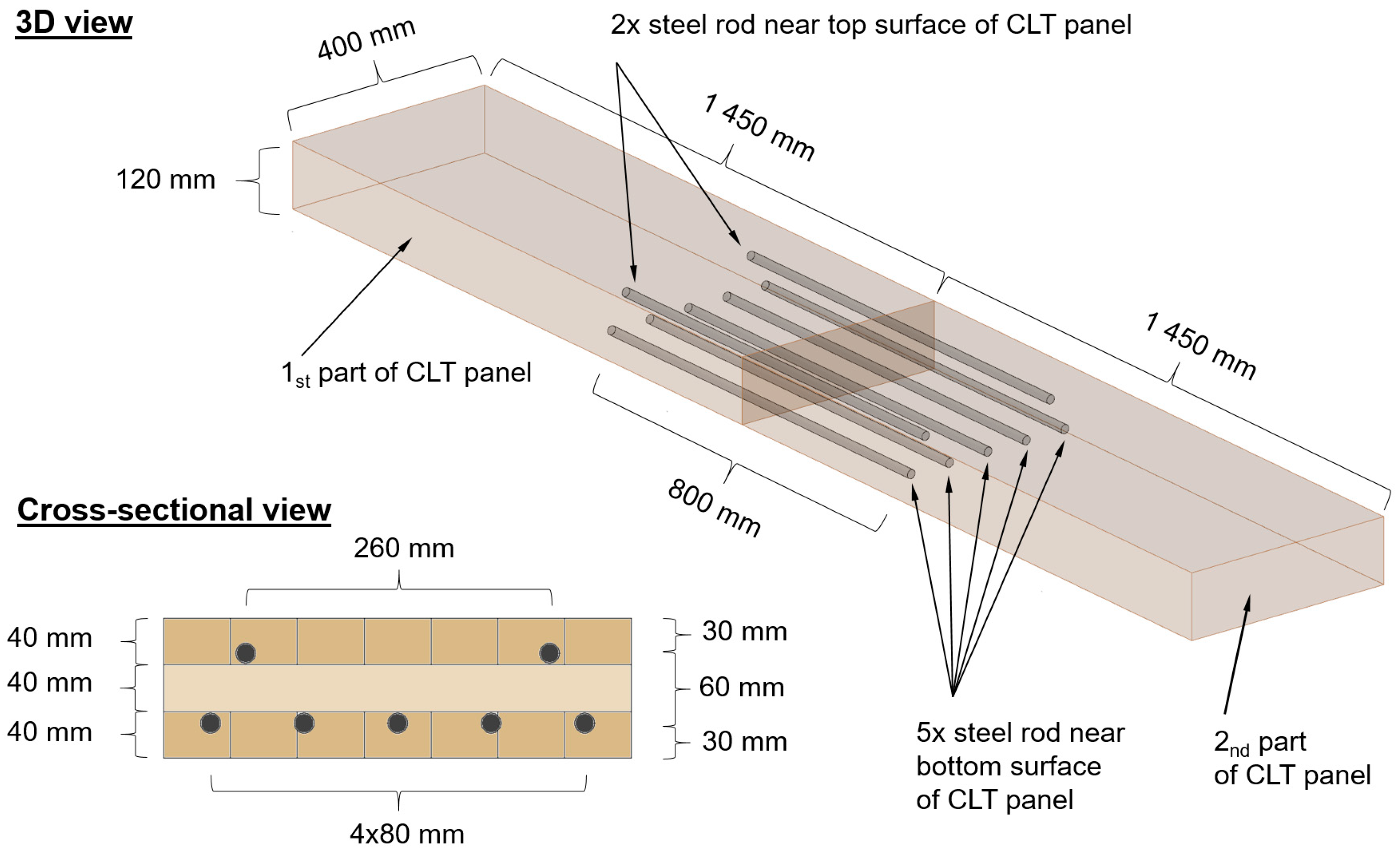
Figure 1. Embedded moment-resisting joint of CLT panels.
Buildings 15 03534 g001
Figure 2. Four series of tested specimens.
Buildings 15 03534 g002
Figure 3. Layout of shear connectors.
Buildings 15 03534 g003
Figure 4. Photograph of the specimen under test.
Buildings 15 03534 g004
Figure 5. Geometric scheme of test set-up for each series.
Buildings 15 03534 g005
Figure 6. Load–displacement behaviour: (a) CLT panels with and without joint; (b) CLT–concrete composite panels with and without joint; (c) CLT panels and CLT–concrete composite panels without joint; (d) CLT panels and CLT–concrete composite panels with joint.
Buildings 15 03534 g006
Figure 7. Relationship between load and joint-gap opening (B1*—estimated data).
Buildings 15 03534 g007
Figure 8. Relationship between min-span displacement and joint-gap opening (B1*—estimated data).
Buildings 15 03534 g008
Figure 9. Surface stress pairs from strain-gauge measurements during four-point bending. (a) Series A and AC. (b) Series B and BC.
Buildings 15 03534 g009
Figure 10. Failure of specimens during experimental testing.
Buildings 15 03534 g010
Figure 11. Ultimate load by series (Mean ± SD) with SLS Marker at L/300.
Buildings 15 03534 g011
Figure 12. Initial stiffness by series (Mean ± SD).
Buildings 15 03534 g012
Figure 13. Normalised stiffness Ksec/K0 versus normalised load F/Fmax: (a) CLT panel without joint; (b) CLT–concrete composite panel without joint; (c) CLT panel with joint; (d) CLT–concrete composite panel with joint.
Buildings 15 03534 g013
Figure 14. Bending moment versus stiffness for CLT panels without concrete slab without (series A) and with joint (series B).
Buildings 15 03534 g014
Figure 15. Bending moment versus stiffness for CLT–concrete composite panels without (series AC) and with joint (series BC).
Buildings 15 03534 g015
Figure 16. Joint-gap opening versus apparent bending stiffness EIapp (B1*—estimated data).
Buildings 15 03534 g016
Figure 17. Energy as area under load–displacement curve.
Buildings 15 03534 g017
Figure 18. Energy vs. load level: (a) CLT panel without joint; (b) CLT panel with joint; (c) CLT–concrete composite panel without joint; (d) CLT–concrete composite panel with joint; (e) comparison of all series.
Buildings 15 03534 g018
Figure 19. Energy build-up by load interval for all specimens.
Buildings 15 03534 g019
Figure 20. Schematic concept of the joint based on component-method model: (a) CLT panel; (b) CLT–concrete composite slab—neutral axis lies in concrete part; (c) CLT–concrete composite slab—neutral axis lies in CLT panel.
Buildings 15 03534 g020
Table 1. Ultimate load with corresponding mid-span deflection and failure mode for all specimens.
SpecimenUltimate Load FmaxDeflection at FmaxFailure Mode
-[kN][mm]-
A148.8045.21shear
A243.1237.26delamination and shear
A348.2437.16partial delamination and shear
B121.3133.71joint
B238.2948.97shear
B344.1445.26partial delamination and shear
AC1105.4327.16shear
AC299.1223.40shear
AC3105.4024.14partial delamination and shear
BC1109.7126.70joint and bending
BC2107.6528.91shear
BC392.4927.44delamination and shear
Disclaimer/Publisher’s Note: The statements, opinions and data contained in all publications are solely those of the individual author(s) and contributor(s) and not of MDPI and/or the editor(s). MDPI and/or the editor(s) disclaim responsibility for any injury to people or property resulting from any ideas, methods, instructions or products referred to in the content.