Article

Investigation on Static Performance of Piers Assembled with Steel Cap Beams and Single Concrete Columns

1
Department of Bridge Engineering, Tongji University, Shanghai 200092, China
2
Department of Urban Management, Kyoto University, Kyoto 602-8570, Japan
3
Shanghai Engineering Research Center of High Performance Composite Bridges, Shanghai 200092, China
4
Singapore Centre for 3D Printing, Nanyang Technological University, 50 Nanyang Avenue, Singapore 639798, Singapore
*
Author to whom correspondence should be addressed.
Buildings 2025, 15(19), 3476; https://doi.org/10.3390/buildings15193476
Submission received: 26 August 2025 / Revised: 19 September 2025 / Accepted: 23 September 2025 / Published: 26 September 2025

Abstract

To reduce the weight of prefabricated cap beams, a new type of hybrid pier with a steel cap beam and single concrete column with an innovative flange–rebar–ultra-high-performance concrete (UHPC) connection structure is proposed in this paper. Focusing on the static performance of hybrid piers, a specimen with a geometric similarity ratio of 1:4 was fabricated for testing. The results showed that the ultimate load-bearing capacity reached 960 kN, and the failure mode was characterized by an obvious overall vertical displacement of 70.2 mm at the cantilever end, accompanied by local buckling in the webs between transversal diaphragms and ribs. Due to the varying-thickness design, longitudinal strains were comparable between the middle section (thin plates) and the root section (thick plates) of the cantilever beam, showing a trend of an initial increase followed by a decrease from the end of the cantilever beam to the road centerline. Meanwhile, the cross-sections of the connection joint and concrete column transformed from overall compression to eccentric compression during the test. At the ultimate state, their steel structures remained elastic, with no obvious damage in the concrete or UHPC, verifying good load-bearing capacity. Furthermore, the finite element analysis showed the new connection joint and construction method of hinged-to-rigid could reduce the column top concrete compressive stress by 18–54%, tensile stress by 11–68%, and steel cap beam Mises stress by 10%. Finally, based on the experimental and numerical studies, the safety reserve coefficient of the new hybrid pier was over 2.7.

1. Introduction

With the rapid advancement of urban modernization and the new energy vehicle industry, traffic congestion in major cities continues to intensify. To address this challenge, elevated bridges, tunnels, and expressways are increasingly constructed to enhance transportation capacity. However, traditional cast-in-place construction methods, characterized by complex procedures, long construction periods, traffic disruptions, and environmental pollution, are no longer compatible with the principles of modern, green, and efficient urban infrastructure. In this context, prefabricated and rapid-assembly technologies have emerged as promising alternatives for large bridge projects [1,2,3].
Presently, prefabricated construction has been widely applied in the superstructures of small- and medium-span urban bridges. Yet, its adoption in substructures, especially cap beams and columns, remain limited. A major obstacle lies in the scale of modern urban expressways, which typically require prestressed concrete cap beams spanning 30–40 m and weighing up to 400 tons. Such massive members present difficulties in transportation, hoisting, and reliable connection to columns [4,5]. Hence, the development of lightweight cap beam design and optimized connection systems is critical for advancing prefabricated bridge substructures [6,7,8,9].
Recent studies have introduced high-performance materials as a potential solution to these challenges. Ultra-high-performance concrete (UHPC) is a steel-fiber-reinforced composite that provides exceptional compressive strength (compressive strength ≥ 150 MPa), high toughness, low permeability, and durability [10,11,12]. High-strength steel (yield strength ≥ 460 MPa) further offers reduced self-weight, high toughness, and favorable workability [5]. As shown in Figure 1, novel cap beams leveraging these materials, such as a fully prefabricated prestressed UHPC thin-walled cap beam [13], prefabricated UHPC shells with cast-in-place core concrete (NC) composite cap beams [14], and long-cantilever high-strength steel–UHPC hybrid cap beams [5], have achieved 40% weight reductions while maintaining robust mechanical performance. Despite these advances, the high cost of UHPC and high-strength steel has restricted widespread adoption, underscoring the need for economical hybrid solutions. Therefore, a hybrid pier combining steel cap beams with concrete columns is proposed in this paper.
Following the 1995 Great Hanshin Earthquake, Japanese engineers promoted steel cap beams for urban bridges due to their prefabrication efficiency and superior seismic performance, with applications in the Hanshin and Fukuoka Expressways [15]. In China, steel cap beams have primarily been used in railway and highway substructures, but their use in urban bridges is limited. Some scholars have conducted research through theoretical analysis and numerical simulations, focusing on the global dimensional parameters of steel cap beams [16], span-to-depth and width-to-depth ratios [17], overall longitudinal stiffness incorporating shear and torsional rigidity [18], seismic performance, and fatigue behavior. Moreover, in terms of experimental research, Shao Xudong et al. [5] performed four-point bending tests on high-strength steel–UHPC composite cap beams to study their flexural capacity and failure modes. Additionally, full-scale and scaled (1:5) tests were carried out on steel–concrete hybrid columns for the Hanshin Expressway, focusing on the mechanical behavior and load-transfer mechanisms [15].
Nevertheless, the connection between steel cap beams and concrete columns remains a critical challenge. Rigid connection forms such as embedded steel columns, steel shoes, bolts, and rebars are widely studied [19,20], while bolted or welded joints are typically used for CFST columns [21]. Recently, an innovative “hinged-to-rigid” method for connections has been proposed [22], enabling temporary hinges during erection that are later transformed into rigid joints, thereby improving load distribution and reducing stresses on columns.
In light of these gaps, this study proposes a novel hybrid pier system comprising a prefabricated steel cap beam and a single concrete column. A new flange–rebar–UHPC connection structure is introduced, constructed through the hinged-to-rigid method. To evaluate its mechanical behavior, a 1:4-scaled hybrid pier model was fabricated and tested under load, with strain and displacement monitored in real time. Complementary finite element analysis was performed to further assess stress transfer mechanisms and safety reserves. The findings aim to provide practical reference for the application of lightweight, prefabricated hybrid piers in urban bridge projects.

2. Test Scheme

2.1. Background Project

This study is based on the project of an Avenue Expressway in Hangzhou, Zhejiang Province, China. In this project, the superstructures of the bridges all adopt continuous beam systems, with three structural forms of prestressed concrete box girders, steel–concrete composite girders, and steel girders. When the main girder is arranged with four lanes, the substructure adopts the form of a single column.
Based on the construction of urban bridges in busy districts under spatial constraints, heavy traffic, and tight schedules, the adoption of prefabricated and assembled substructures becomes imperative. Comprehensive evaluation indicates that steel box cap beams offer advantages such as being lightweight and having high-strength properties, reduced carbon emissions, and high prefabrication potential. Additionally, on-site construction is convenient and efficient, reduces noise and pollution, and minimizes disruption to existing traffic. Therefore, this approach holds significant social value and aligns with the principles of green building development.

2.2. Scale Ratios

In structural mechanics experiments, the geometric similarity ratio serves as a critical parameter for evaluating dimensional correspondence between the model and prototype, which directly influences the simulation accuracy and reliability of test results.
This test model uses a geometric similarity ratio of 1:4 relative to the actual structure, which not only accurately simulates material properties, boundary conditions, and loading conditions but also addresses challenges related to fabrication, transportation, site constraints, equipment, and cost. Additionally, the similarity ratios for area, volume, concentrated load, bending moment, stress, and strain are 1:16, 1:64, 1:16, 1:64, 1:1, and 1:1, respectively.

2.3. Specimen Design

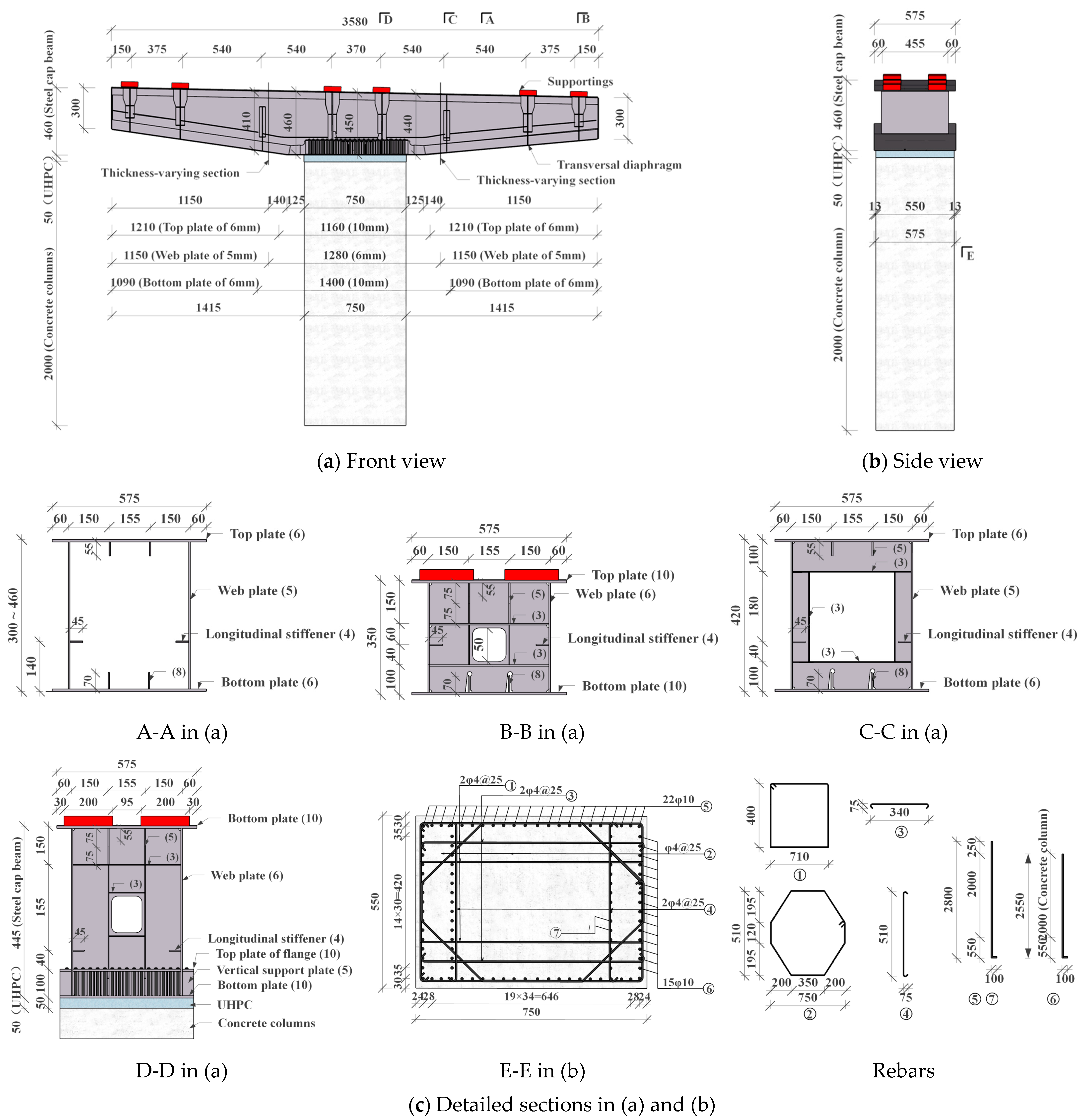
The specimen for testing was designated as SSM, primarily composed of a steel cap beam, a steel–concrete connection joint, and a reinforced-concrete pier, as shown in Figure 2.
(1)
Steel cap beam
The steel box cap beam was fabricated by welding Q355 steel plates of varying thicknesses, with a total longitudinal length of 3580 mm. This included the cantilever beam (1415 mm) extending beyond the concrete column and the beam of the connection joint over the column top (750 mm). The height of the cantilever webs increased linearly from 300 mm at the end sections to 440 mm/460 mm at the root sections, with the top plate featuring a 2% longitudinal slope. However, the beam above the column exhibited minimal height variation.
The width of both the top plate and bottom plate of the steel cap beam was 575 mm, while the spacing between the webs was 450 mm. This design served two purposes: (1) to reduce the on-site construction difficulty for rebar anchoring in the flange–rebar–UHPC connection; and (2) to position the webs directly beneath the support centers of the top plate, enabling them to directly resist and transfer the superstructure loads, thereby minimizing distortion and torsional effects in the steel box girder.
Furthermore, under concentrated loads, the bending moment and shear force diagrams of the cantilever beam exhibited a stepped distribution. The shear force surged abruptly beneath each support, accompanied by increased moment gradients, reaching their peak values simultaneously at the root section. A constant-thickness design would have resulted in the resistance at the cantilever end significantly exceeding the applied loads, leading to low steel utilization and material waste. Therefore, considering that shear forces between the end and root supports remained nearly constant (due to self-weight alone), implementing a varying-thickness section near section C was justified. The design principle required that longitudinal stresses in the top and bottom plates at the variable-thickness section (thinner plate side) and the cantilever root section approached equivalence, while the shear capacities of both webs satisfied the relevant code requirements.
Finally, longitudinal stiffeners were provided on the inner surfaces of the top plate, webs, and bottom plate to enhance structural stiffness and prevent local buckling. Additionally, rigid diaphragms were installed beneath each support, with transverse ribs positioned between the end and root supports.
(2)
Reinforced-concrete column
As shown in Figure 2c, the reinforced-concrete column of specimen SSM had a height of 2000 mm, with the rectangular cross-section measuring 550 mm (transverse) × 750 mm (longitudinal). The rebar cage consisted of multiple HRB400 rebars. Among these, the vertical main rebars (⑤, ⑥, ⑦) had a diameter of 10 mm. Since rebars ⑤ and ⑦ penetrated the bottom plate of steel cap beam and anchored into the flange, the rebar ⑥ was embedded in concrete column below the bottom plate. The remaining rectangular ties (①), diamond ties (②), and horizontal tensile bars (③, ④) had a diameter of 4 mm, all serving to confine the core concrete and reinforce the rebar cage. Consequently, the concrete column was cast in-place, with samples of concrete taken for material performance testing.
(3)
Connection joint
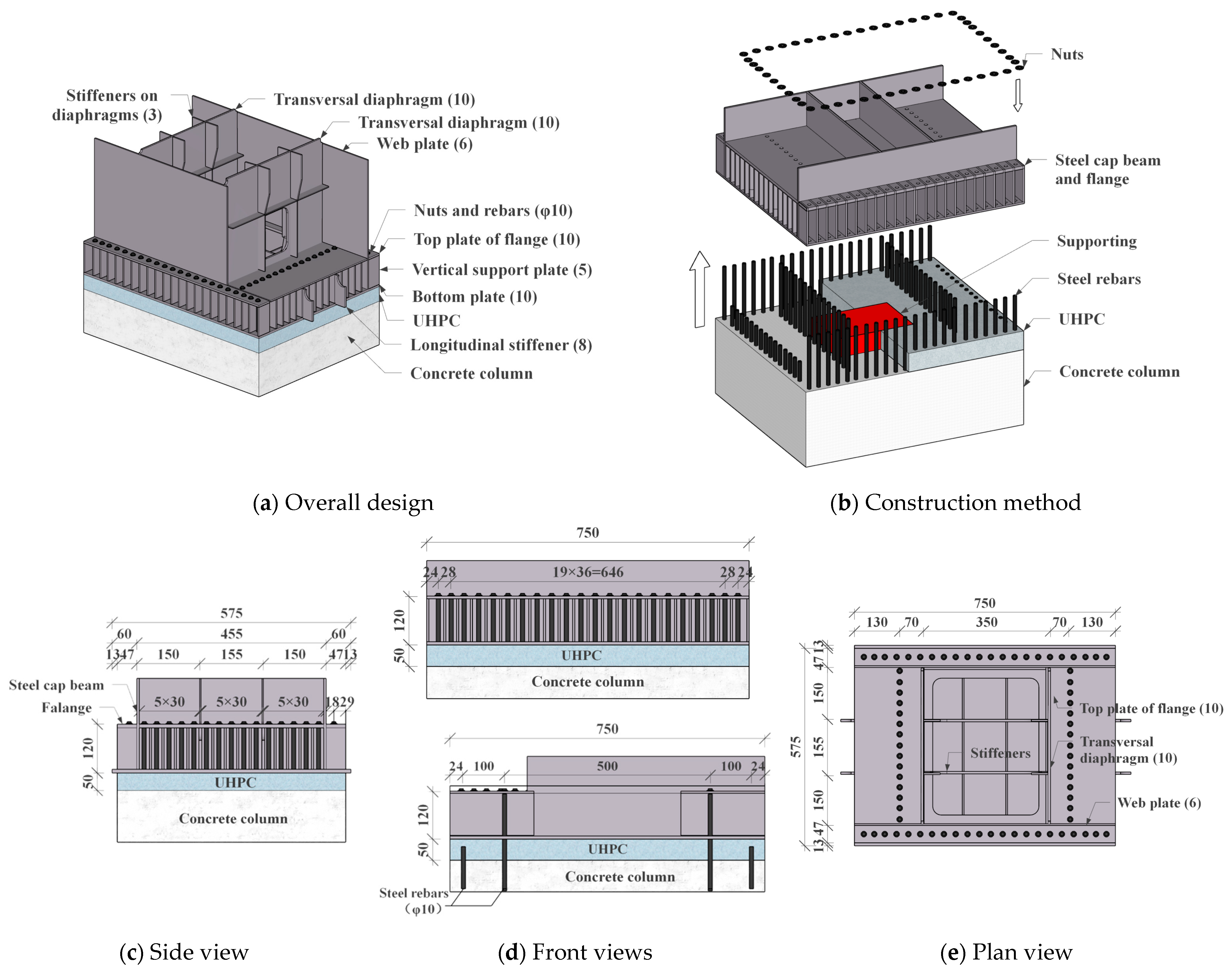
The connection joint employed the novel flange–rebar–UHPC structure, with the detailed design shown in Figure 3. The size of the flange was matched to the concrete column to facilitate the passage of rebars and the installation of the steel cap beam.
As shown in Figure 3b, the construction sequence in actual projects is as follows: (1) Place the elastomeric bearing on top of the concrete column. (2) Hoist the entire steel cap beam and position it on the bearing, threading the vertical rebars through its bottom plate and flange. (3) Preliminarily tighten the bolts to prevent the main girder from overturning. (4) After the substructure has stabilized under the self-weight of the superstructure, cast the UHPC at the connection joint and tighten the bolts. (5) Construct the bridge deck paving, parapets, and other ancillary components.
Moreover, the surface of rebars anchored to flange will be protected by coating to prevent corrosion. Meanwhile, steel plates will be used to seal the area between vertical support plates at connection joint, avoiding excessive contact between rebars and air, which could lead to corrosion.

2.4. Specimen Fabrication

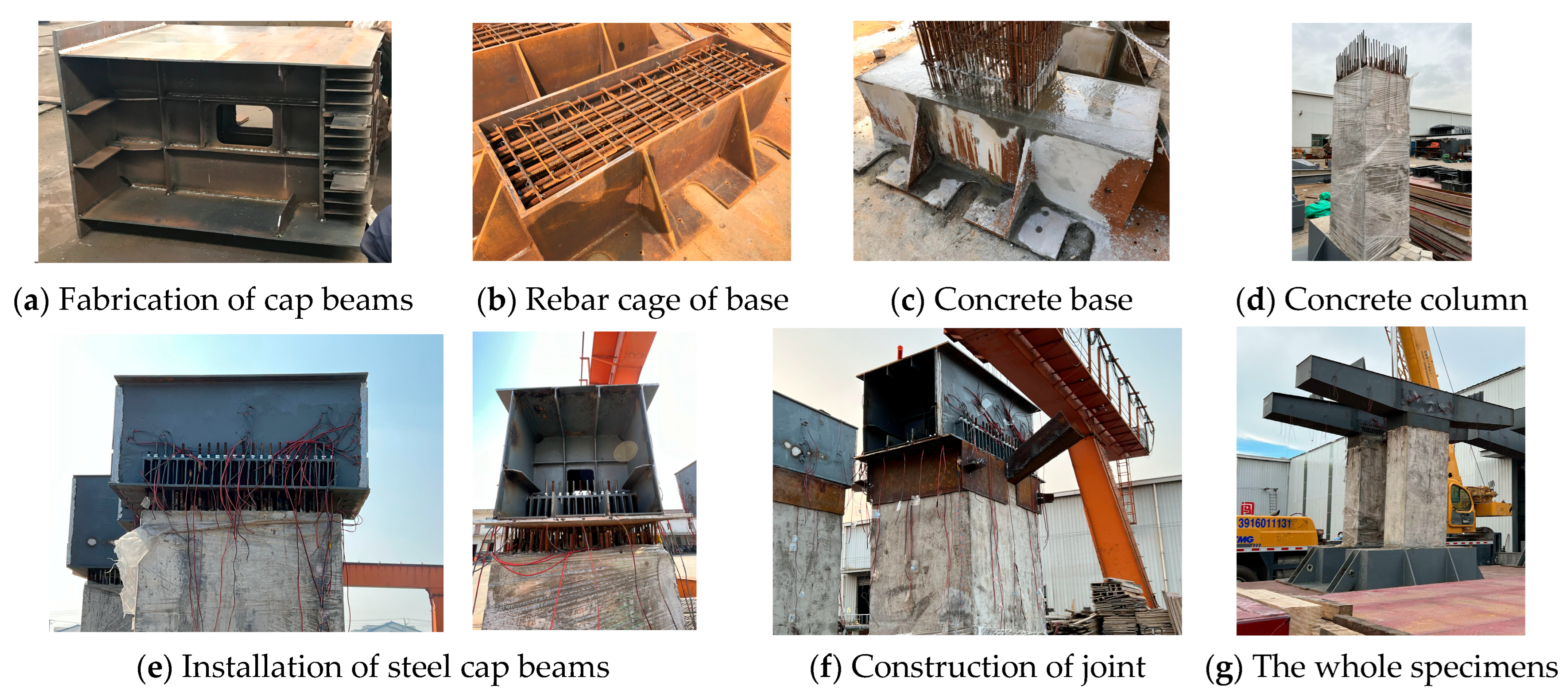
Specimen SSM was constructed as shown in Figure 4, with the construction sequence as follows: (a) Weld segments of the steel cap beam. (b) Assemble the rebar cage of the concrete base. (c) Assemble the rebar cage of the column and cast the concrete base. (d) Cast the concrete column. (e) Install the connection joint by tightening the bolts preliminarily. (f) Cast the UHPC and tighten the bolts finally. (g) Complete the specimen SSM.
However, due to the scale ratio of 1:4, the internal clearances of the steel cap beam were too small to tighten the bolts and weld the plates. During the fabrication, the bolts were tightened only once, and the conversion between hinged and rigid connections by casting the UHPC and tightening the bolts during loading was unachievable. Consequently, all loads were applied to hybrid piers with fully monolithic connections, and the hinged-to-rigid construction sequence could not be simulated in test but was carried out by the finite element method.

2.5. Test System and Scheme

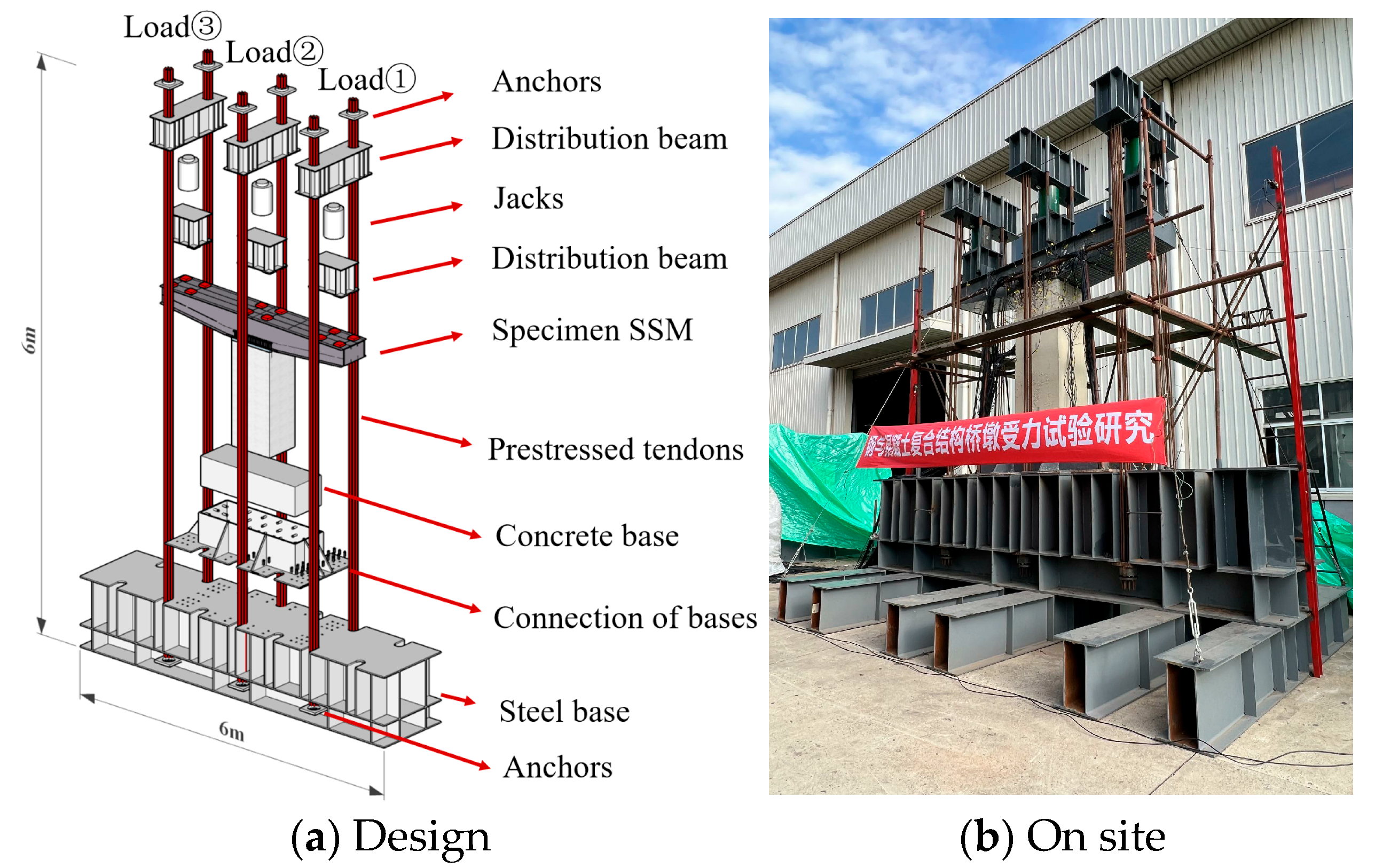
The loading in the test employed the self-reaction system shown in Figure 5. In this system, two ends of prestressing tendons were anchored to the upper distribution beams and reinforced steel base, and jacks could apply loads to the top plate of steel cap beam after tensioning prestressed tendons, during which all gaps in the device were eliminated. Moreover, each jack was controlled independently, so different loads could be distributed uniformly to support positions.
As shown in Figure 5a, Load ① was applied at the cantilever end on the side of lower height, Load ③ was on the opposite end, and Load ② was on the concrete column.
The loading scheme comprised five stages, as detailed in Table 1. The first was preloading, where all jacks were loaded to 40 kN and then unloaded to verify the specimen and equipment. Then, in step 1, the self-weight of the main girder was 148 kN, while that of auxiliary structures was 60 kN in step 2. Meanwhile, according to the actual bridge specifications outlined by the General Specifications for Highway Bridge Design (JTG D60-2015) [23], live vehicle loads under the serviceability limit state can only produce 8600 kN·m of bending moment and 2200 kN of vertical axial force at the top of the concrete column, which was equivalent to 134 kN·m and 138 kN in the test, respectively. Considering that the distance from the end to the root of cantilever beam was 0.99 m, Load ① of 138 kN generated a 137 kN·m bending moment at the column top. Thus, the total of Load ① was 346 kN, and that of Loads ② and ③ was 208 kN each in step 3. Additionally, steps 1, 2, and 3 were executed in 5, 10, and 20 equal increments, respectively, with data recorded after each increment, while step 4 continued loading until the specimen failure.

2.6. Measurement Scheme

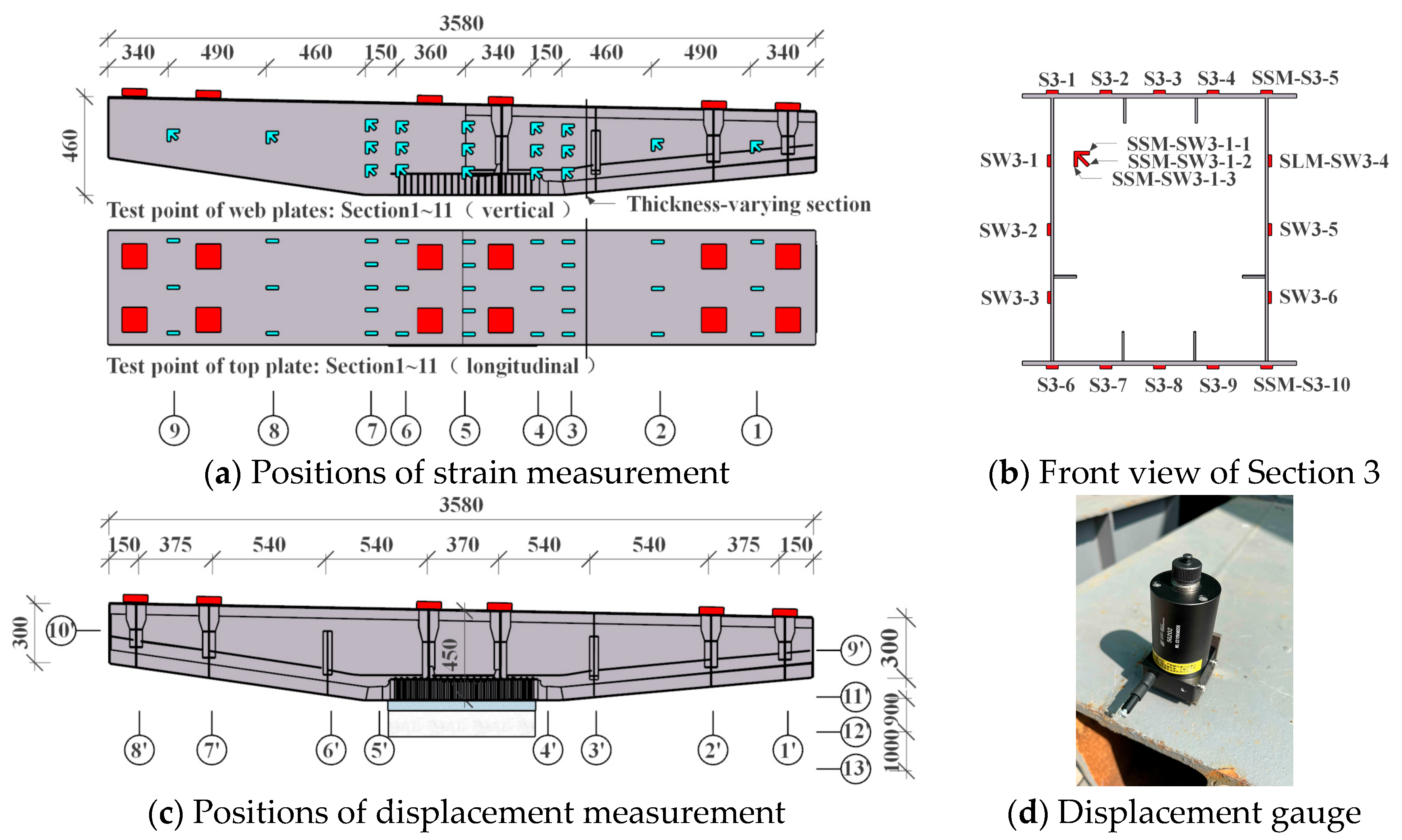
During the test, the jack loads, strain, and displacement at critical sections 1–9 were measured in real time for subsequent processing and analysis. For the steel cap beam, longitudinal strain gauges on the top and bottom plates, along with shear strain gauges on the web, are illustrated in Figure 6a,b, and as shown in Figure 6c,d, displacement gauges were used to measure the vertical displacements at sections 1′–8′ and horizontal displacements at sections 9′–13′.

3. Test Results

3.1. Material Property Testing

During the fabrication of specimen SSM, samples of the steel plate, concrete, and UHPC were retained for property testing. Material tests were conducted for each material, and mean values are reported in Table 2 and Table 3.
Steel tensile testing was performed according to the standards of Metallic Materials-Tensile Testing (GB/T 228.1-2021) [24], and the elastic modulus was taken as 206 GPa according to the Code for Design of Steel Structures (GB50017-2017) [25]. Additionally, the material properties of the rebars were provided by the professional testing institution.
The concrete for the column and the UHPC for the connection joint were tested in accordance with the standards of Test Methods of Physical and Mechanical Properties of Concrete (GB/T 50081-2019) [26]. It should be noted that the compressive strength of the C40 concrete measured through material performance tests was 27.5 MPa, which is lower than the standard strength of 40 MPa. On the premise that the concrete mix proportion was correct, the lower strength might have been caused by the influence of on-site environmental factors and pouring construction. However, it was clear that this compressive strength of 27.5 MPa is the actual data in this test, and subsequent specimen tests and finite element models were all carried out using this data.

3.2. Experimental Phenomenon and Failure Mode

The experimental phenomena of specimen SSM at different loading steps were as follows: (1) During loading steps 1–3, the hybrid pier remained in the elastic phase, and the cantilever beam was subjected to bending moment and shear force, with its top plate in tension and bottom plate in compression. (2) In step 4, when Load ① reached 919 kN and Loads ② and ③ reached 549 kN, both the top and bottom plates at section 2 of the cantilever beam yielded first, while the root section remained elastic. Then, the yielded zones of the steel plates expanded gradually, accompanied by a reduction in the flexural stiffness of the cantilever beam. (3) Finally, specimen SSM reached its ultimate load-bearing capacity when Load ① was 960 kN and Loads ② and ③ were 569 kN. Fracturing sounds emanated from the steel cap beam, significant overall deflection occurred at the end of the cantilever beam beneath the support of Load ①, and local buckling occurred in both side webs at section 2 between the transverse ribs and diaphragms.
As illustrated in Figure 7, the failure mode of specimen SSM primarily involved local buckling of the webs at section 2 of the steel cap beam. Specifically, buckling 1 manifested as localized out-of-plane deformation, which propagated from the mid-height of the transversal diaphragm toward the top of the transversal rib. Simultaneously, the other web at this section exhibited similar local buckling, buckling 2, while the top and bottom plates between these webs remained intact without localized deformation.
Furthermore, the results of the observation and measurement confirmed that the flange of the connection joint showed no significant deformation or damage, with no slippage in nuts or rebars. Concurrently, neither crushing nor tensile cracking were detected at the top of the concrete column or UHPC, as shown in Figure 7c.

3.3. Load–Displacement Response

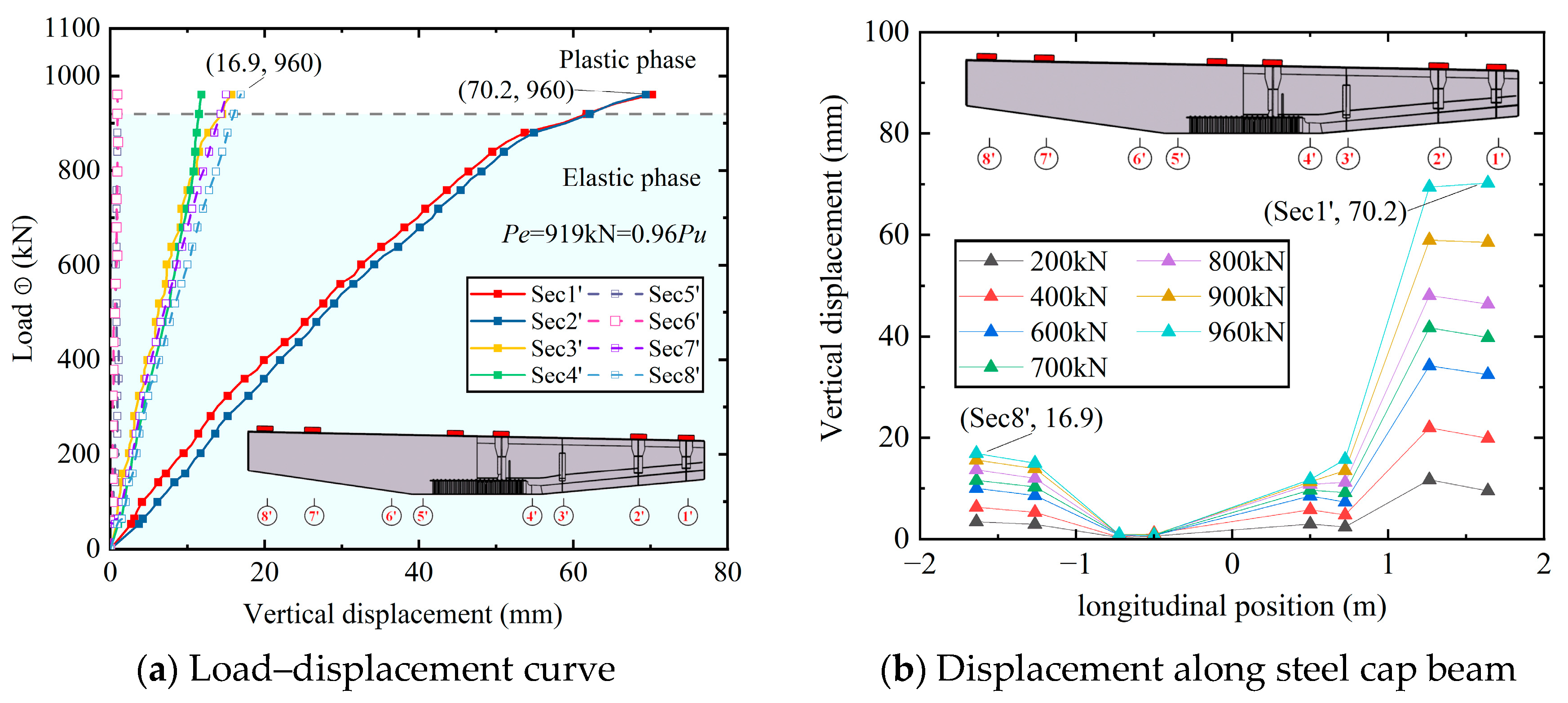
The load–vertical displacement response at various sections of the steel cap beam of specimen SSM is shown in Figure 8, with downward displacement defined as positive and upward as negative. However, the steel base under the hybrid pier exhibited sufficient stiffness, resulting in almost no vertical deformation.
During the elastic phase, the vertical displacement of the cantilevered beam exhibited linear growth with the increase in load. Notably, the growth rate of the displacement on the side subjected to higher loads (Load ①) significantly exceeded that on the opposite side. After reaching the plastic phase, the vertical displacements at sections 1′ and 2′ increased rapidly, and at the ultimate state, the maximum vertical displacement reached 70.2 mm at section 1′ and 16.9 mm at section 8′, corresponding to 1/18 and 1/76 of the cantilever length, respectively.
Moreover, combined with the failure mode shown in Figure 7, pronounced deflection was observed in the beam between end sections 1′ and 2′, and it can be concluded that there was discontinuous bending deformation of the entire cantilever beam. This can be attributed to the shear forces induced by the concentrated loads on the webs. Compared to the middle segment of the cantilever beam, which was reinforced solely by transverse ribs over a longer span, the end segment, featuring densely arranged diaphragms, exhibited higher localized stiffness, resulting in overall deflection under concentrated loads.
Lastly, the horizontal displacements measured at sections 9′ to 13′ did not exceed 6 mm throughout the entire loading process.

3.4. Load–Strain Response

(1)
Steel cap beam
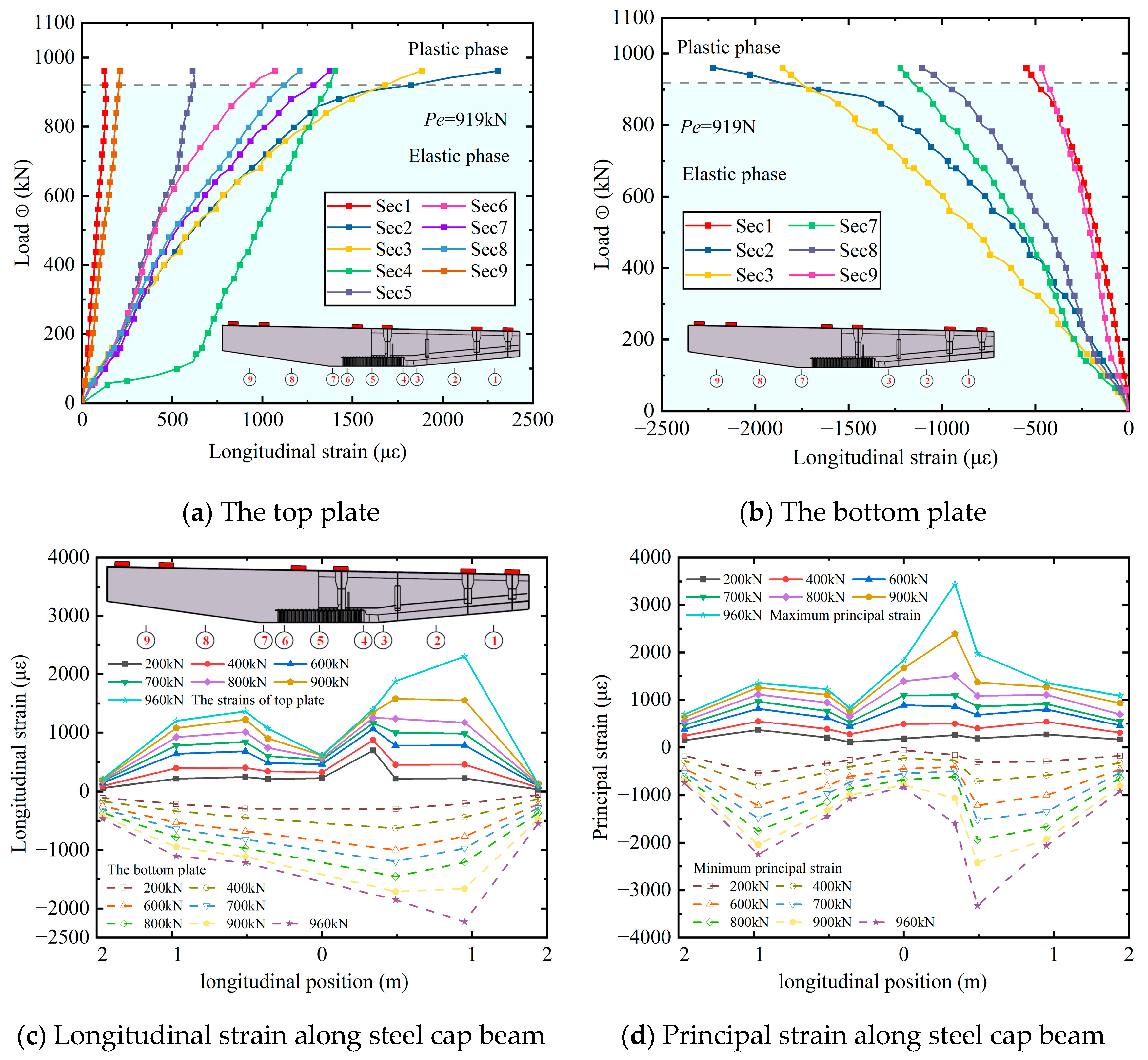
The load–strain response is shown in Figure 9, including the longitudinal strain of the top and bottom plates, along with the shear strain of the webs of the steel cap beam. Herein, longitudinal strain represented the maximum value measured from identical components at the same cross-section, while positive values indicated tension and negative values compression.
As shown in Figure 9a,b, during the elastic phase, the longitudinal strains of the top and bottom plates increased approximately linearly with the applied load. It was evident that the top and bottom plates at section 2 yielded first, after which the strain growth rate significantly increased. Ultimately, when Load ① reached 960 kN, specimen SSM failed. At this point, the maximum longitudinal strains at section 2 were 2305 με (top plate) and 2228 με (bottom plate).
Overall, the longitudinal strains of the top and bottom plates exhibited a pattern of an initial increase followed by a decrease from the cantilever end sections toward the road centerline section (sections 1–5, 9–5). Due to the varying-thickness design of the steel cap beam, the longitudinal strains at the varying-thickness sections (section 2, section 3) and the cantilever root section (section 4) were comparable, as confirmed by the test results. This design optimized material utilization and conserved steel.
Additionally, in accordance with the specifications of Code for Design of Steel Structures GB 50017-2017 [23], the design value of the shear strength for Q355 steel plates is τy = 175 MPa, so the proportional limit of the shear τp = 0.8τy = 140 MPa. The stress of shear buckling is calculated by the formula τ c r = χ s × 5.34 π 2 E 12 ( 1 ν 2 ) ( h 0 / t w ) 2 . For the constraint condition of the web, χ s = 1.23. The shear buckling stress of the web where local buckling occurs is calculated as follows: τ c r = 1.23 × 5.34 × π 2 × 206,000 12 ( 1 0.3 2 ) ( 355 / 5 ) 2 = 242   M P a > 140   M P a . Meanwhile, the elastoplastic shear buckling stress is calculated as τ c r = τ p τ c r = 184   M P a > 175   M P a . Therefore, elastoplastic buckling failure should not occur in theory. However, in the test, the first and third principal strains measured at both webs in this region were 1974 με and −2064 με, respectively, corresponding to an approximate stress of 350 MPa, which is much higher than the elastoplastic shear buckling stress. As a result, shear buckling failure occurred, as shown in Figure 9d.
(2)
Connection joint
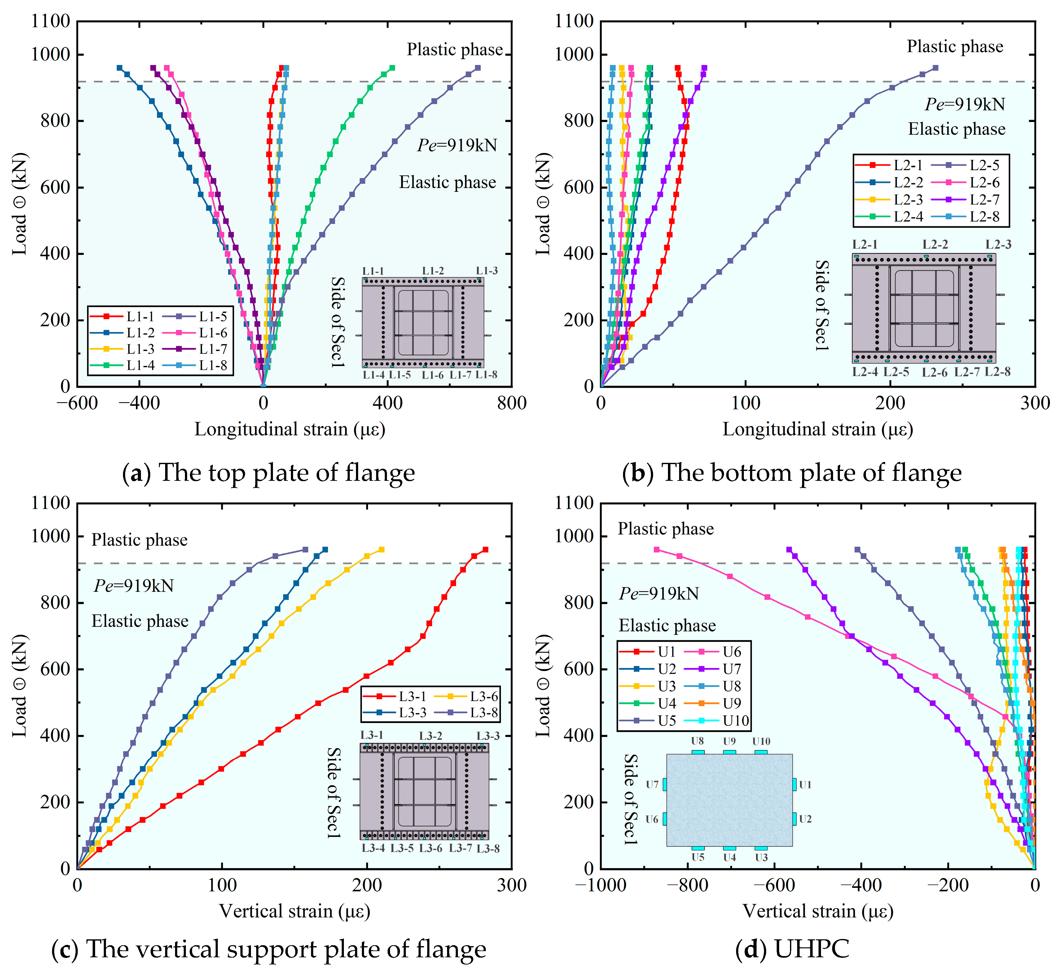
Specimen SSM employed a novel flange–rebar–UHPC connection joint, and the longitudinal strains of the top and bottom plates of the flange, along with the vertical strain of the vertical support plates and UHPC, were measured, as shown in Figure 10.
Figure 10c,d reveals that the flange and UHPC were subjected to eccentric compression, with the entire cross-section being in compression. The vertical compressive strain on the side of the higher load increased continuously, while that of the opposite measurement points (U1, U2, U3, and U10) increased initially and then decreased, with the transition occurring at loading step 2.
Furthermore, at the ultimate state, none of the steel plates in the connection joint yielded, indicating substantial safety reserves. Combined with the fact that no obvious deformation or damage to the connection joint was observed during the test, this novel structure demonstrated high load-bearing capacity.
(3)
Reinforced-concrete column
To investigate the mechanical behavior and load transfer mechanism of the reinforced-concrete column, sections 10, 12, 13, and 14 were selected for measuring the rebars, while sections 12, 14, and 15 were designated for the concrete surface. The load–strain response of the reinforced-concrete column is shown in Figure 11.
From the load–strain curves, it can be observed that the entire cross-section of the column top was in compression during symmetric loading in step 1. As Load ① increased in steps 2–4, the vertical compressive strains of both the rebars and the concrete surfaces on this side continuously increased. Conversely, the measurement points on the opposite side transitioned to tensile strain and increased gradually.
From the strain distribution along the concrete column, the load was gradually transferred from the rebars of the connection joint to the concrete column. The similar distribution patterns of vertical strains in both the rebars and the concrete indicated coordinated deformation and composite action between the materials.
Lastly, the maximum vertical compressive strain in the rebars at the ultimate state reached 1067 με (section 12-R9), remaining elastic. Although the vertical strain on the concrete surface was relatively large, no significant damage was observed during the test.

4. Numerical Study

4.1. Finite Element Model

According to the test results, the novel flange–rebar–UHPC connection joint demonstrated good load-bearing capacity. However, specimen SSM was unable to simulate the hinged-to-rigid construction process due to the small geometric similarity ratio. Therefore, to further investigate the enhancement effect of this new connection on the mechanical performance of concrete columns, and to facilitate its application in practical engineering, a three-dimensional finite element model of the hybrid pier was established using the ANSYS Mechanical APDL 2024R1 software, as shown in Figure 12.
In this finite element model, the steel plates of cap beam were simulated using Shell181 elements, the concrete column and UHPC were simulated by Solid65 elements, and the rebars were simulated by Link8 elements. Meanwhile, the following assumptions were made: (1) adopt the actual thickness of the steel plates shown in Table 2 and a nonlinear elastic–plastic constitutive model; (2) adopt a linear elastic constitutive model of the concrete and UHPC and consider the geometric nonlinear effects; (3) assume no slip between the rebars and concrete due to enough anchorage length; (4) ignore the restraining effect of horizontal rebars; and (5) consider the initial deformation of the specimen induced during transportation and installation. This deformation was calculated under the condition of first-order global buckling, with its maximum value specified as L/1000, where L represents the length of the cantilever beam. However, the global instability modes of the first to fifth orders were calculated, respectively, and introduced into the new finite element model as initial geometric imperfections. The difference in the ultimate load-bearing capacity obtained from the calculations was only 0.7%. Therefore, it is feasible to adopt the deformation of the first-order global instability mode.
To analyze the sensitivity of the mesh size, finite element models with mesh sizes of 300 mm and 400 mm were established, respectively, for the hybrid pier with a total length of 14,320 mm, as shown in Figure 13.
The comparison of the calculation results is shown in Table 4. At different loading steps of the two finite element models, the maximum compressive stress and tensile stress of the steel cap beams were quite close, and the difference in the ultimate load-bearing capacity was only about 1.5%. Therefore, a mesh size of 300 mm is reasonable.

4.2. Comparison Between Experiment and Finite Element Analysis

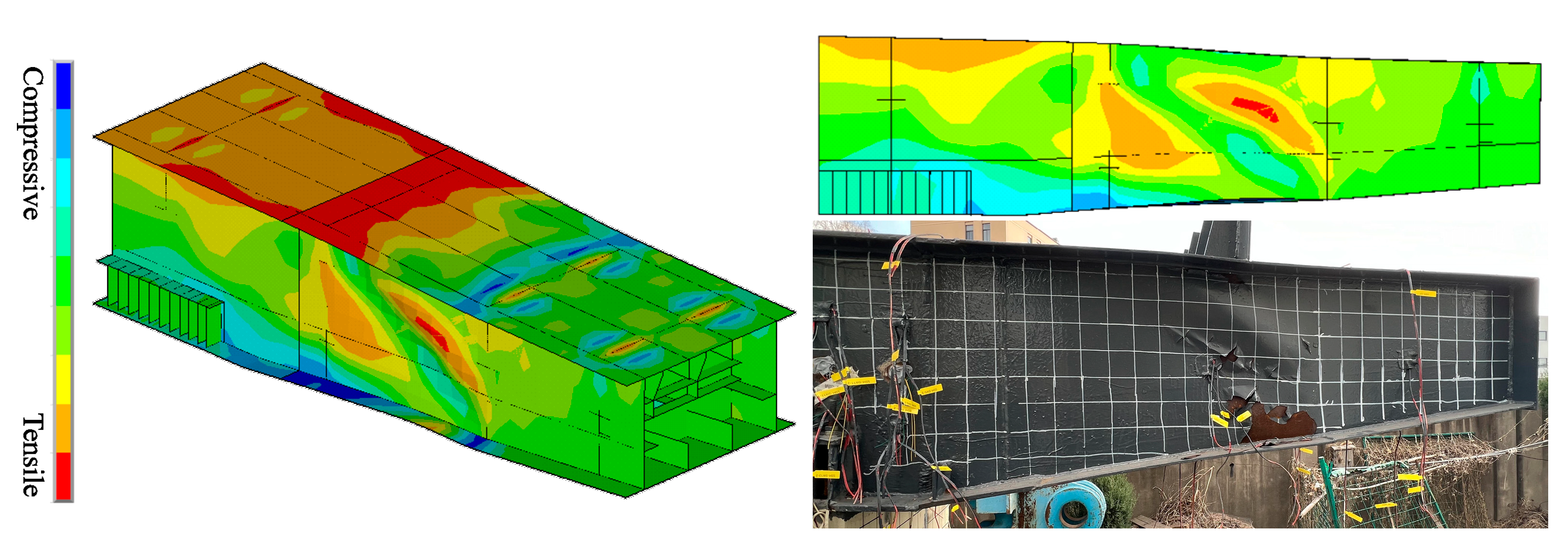
Using the loading scheme specified in Table 1, the ultimate load-bearing capacity of the finite element model SSM was calculated. The results showed that when Load ① reached 988 kN and Load ② and Load ③ reached 589 kN, the structure failed, with a deviation of only 3% from the test results. Meanwhile, the longitudinal strain contour plot of the steel cap beam at the ultimate state, shown in Figure 14, indicated that the failure mode of the finite element model was characterized by local buckling of the webs and overall deflection at the end of the cantilever beam, demonstrating strong similarity to the failure mode observed in the test. Therefore, the finite element model was considered accurate.
Assuming that the safety reserve coefficient is defined as the ratio of the ultimate load-bearing capacity (Pu) to the serviceability limit state load (Ps), the value for specimen SSM, as determined through both the test and finite element analysis, was over 2.7, indicating a highly safe design. Furthermore, it is worth noting that this safety reserve coefficient represents the multiple by which the dead load of the main girder and auxiliary structures and the live load are scaled-up simultaneously, instead of the scenario where only the live load is scaled-up while the dead load remains unchanged. Therefore, the safety coefficient proposed in this paper is both reasonable and conservative.

4.3. The Hinged-to-Rigid Construction Method

Based on the finite element model, the influence of the flange–rebar–UHPC connection with the hinged-to-rigid construction method on the mechanical properties of the single-column pier was analyzed. Detailed consideration was given to the construction steps, including the installation of the three main girders, as shown in Figure 15, the construction of auxiliary facilities of the superstructure, and the application of live loads. A comparison of different construction methods is presented in Table 5.
The comparison of the different construction methods is presented in Table 5. While installing the main girders in sequence, the new method could effectively reduce the vertical compressive stress on the concrete at the pier top by up to 54%, and it could reduce the vertical tensile stress by up to 44%. Furthermore, on the basis of reducing the stress and deformation of the concrete piers by releasing the bending moments, it could further reduce the vertical compressive stress by 43% and the vertical tensile stress by 68% during the construction of auxiliary facilities. In addition, the vertical stress could be reduced by approximately 31% at the serviceability limit phase. Moreover, the Mises stress of the steel cap beams was also reduced by 10% in each stage.
Overall, the new connection joint and construction method showed a significant improvement in terms of the mechanical performance of the hybrid piers during the construction and operation stages, which could solve the cracking problem caused by excessive tensile stress in the concrete at the pier top and connection joint. Therefore, this is of great significance to the design and construction of hybrid piers.
As shown in Table 5, the novel flange–rebar–UHPC connection joint and construction method significantly improved the mechanical performance of the steel cap beam and concrete column. Specifically, during the installation of the main girders, this method reduced the vertical compressive stress at the top of the concrete column by 18–54%, and more importantly, it reduced the vertical tensile stress by 11–68%. In addition, the Mises stress of the steel cap beam was reduced by approximately 10%. Therefore, this method is strongly recommended.

5. Conclusions

This paper proposes a new type of prefabricated steel cap beam–single-concrete-column hybrid pier, which adopts a novel flange–rebar–UHPC connection structure. Through experimental and numerical studies on the static performance of hybrid piers, the following conclusions were drawn:
(1) In the test of a 1:4-scale large-scale specimen SSM, the steel cantilever beam was subjected to bending moment and shear force, and the top and bottom plates of section 2 between the transverse diaphragms and ribs yielded first. Eventually, the ultimate load-bearing capacity of specimen SSM was 960 kN, with the failure mode characterized by an obvious overall vertical displacement of 70.2 mm at the cantilever end, and local buckling occurred in the webs on both sides of section 2.
(2) The load–strain response of the steel cap beam showed that the longitudinal strains of the top and bottom plates exhibited a pattern of an initial increase followed by a decrease from the cantilever end sections toward the road centerline section. Meanwhile, due to the varying-thickness design of the steel cap beam, the longitudinal strains at the varying-thickness section (thin plate) and the cantilever root (thick plate) were comparable, and the test results were consistent with this trend. In addition, the maximum and minimum principal strains of the webs peaked near the transverse ribs, which was consistent with the locations of local buckling.
(3) During the test, the cross-sections of the connection joint and concrete column transitioned from an overall compression state to an eccentric compression state. At the ultimate state, the steel structures of both remained elastic, and no obvious damage was observed in the concrete or UHPC during the test, which demonstrated the good load-bearing capacity.
(4) The finite element analysis indicated that the novel flange–rebar–UHPC connection joint and the hinged-to-rigid construction method could reduce the vertical compressive stress at the top of the concrete column by 18–54% during the installation of the main beam. Meanwhile, they could also reduce the vertical tensile stress by 11–68% and decrease the Mises stress of the steel cap beam by approximately 10%. Therefore, the new connection structure and construction method significantly improved the mechanical properties of the hybrid pier.
(5) Based on the experimental and numerical studies, the safety reserve coefficient of the new hybrid pier was over 2.7. Moreover, this study provides a valuable reference for similar bridge projects.
(6) In terms of future research, the hybrid pier with the steel cap beam and concrete column mentioned in this paper has been applied in urban viaduct bridges using rapid construction technology. On the basis of conducting experimental and numerical studies on the static performance of hybrid piers, future research may focus on the fatigue performance of the piers, especially that of the steel cap beam and connection joints, as well as the management, maintenance, repair, and renewal of the structure throughout its entire life cycle. For example, the lifespan of the hybrid pier can be extended by replacing the steel cap beam.

Author Contributions

C.S.: Conceptualization, Formal analysis, Data curation, Writing—original draft; Q.S.: Conceptualization, Funding acquisition, Project administration, Supervision, writing—review and editing; S.W.: Investigation, Supervision, writing—review and editing; F.O.M.: Software, writing—review and editing. All authors have read and agreed to the published version of the manuscript.

Funding

Support from the National Natural Science Foundation of China (52478197) is acknowledged. Support for Chong Shen from the China Scholarship Council (202306260161) is acknowledged. The authors also acknowledge the support and assistance from Tongji Architectural Design (Group) Co., Ltd., and Shanghai TXMEC Technology Co., Ltd.

Data Availability Statement

Most of the data have been provided in the manuscript, and others are available from the corresponding author upon reasonable request.

Conflicts of Interest

The authors declare no conflict of interest.

References

  1. Wang, X.; Li, W.S.; Liu, Z. Experimental investigation and fragility analysis on seismic performance of precast UHPC hollow piers under varying axial load. Soil Dyn. Earthq. Eng. 2025, 196, 109420. [Google Scholar] [CrossRef]
  2. Xie, W.; Zhang, B.J.; Yu, L.T.; Su, Q.; Matanmi, F.O. Flexural Performance of an Innovative Girder-to-Pier Joint for Composite Bridges with Integral Piers: Full-Scale Test. Materials 2025, 18, 1157. [Google Scholar] [CrossRef]
  3. Wang, S.Z.; Su, Q.T.; Jiang, X.; Michels, J.; Ghafoori, E. Fully bonded iron-based shape memory alloy for retrofitting large-scale bridge girders: Thermal and mechanical behavior. Structures 2024, 65, 106710. [Google Scholar] [CrossRef]
  4. Ge, J.P.; Mei, D.L.; Yan, X.F.; Wang, Z.Q. Comparison and analysis of construction method of precast pier cap. J. Technol. 2018, 18, 56–62. [Google Scholar] [CrossRef]
  5. Shao, X.D.; Zeng, H.Q.; Cao, J.H. Flexural behavior of fully prefabricated large-cantilevered high strength steel-UHPC composite bent caps. J. Constr. Steel Res. 2023, 204, 107856. [Google Scholar] [CrossRef]
  6. Hu, H.; Wang, J.W.; Yan, X.F.; Ge, J.; Zhang, D. Experimental research and numerical analysis on mechanical behavior of lightweight-design precast bent caps with large cantilevers. Structures 2022, 40, 536–554. [Google Scholar] [CrossRef]
  7. Hu, F.J.; Yang, C.H.; Zhou, P.M.; Hu, H.; Wang, Y.C. Experimental study on mechanical behavior of precast large-cantilevered UHPC bent caps with π-shaped cross-sections. Structures 2024, 62, 106333. [Google Scholar] [CrossRef]
  8. McKee, C.D.; Lee, J.D.; Birely, A.C.; Mander, J.B. Experimental Behavior of Pretensioned Bent Caps with Internal Voids for Weight Reduction. J. Bridge Eng. 2020, 25, 04019123. [Google Scholar] [CrossRef]
  9. Birely, A.C.; Yole, K.J.; Lee, J.D.; McKee, C.D.; Mander, J.B. Experimental Behavior of Reinforced Concrete and Pretensioned Concrete Bent Caps. J. Bridge Eng. 2019, 25, 04019137. [Google Scholar] [CrossRef]
  10. Ye, M.; Li, L.; Hu, F.J.; Wang, L.; Shao, X. UHPC-based precast large-cantilevered thin-walled bent caps: Design and experiments. Eng. Struct. 2022, 272, 114909. [Google Scholar] [CrossRef]
  11. Khan, M.; Uy, B.; Tao, Z.; Mashiri, F. Behaviour and design of short high-strength steel welded box and concrete-filled tube (CFT) sections. Eng. Struct. 2017, 147, 458–472. [Google Scholar] [CrossRef]
  12. Deng, E.; Zhang, Z.; Zhang, C.; Tang, Y.; Wang, W.; Du, Z.; Gao, J. Experimental study on flexural behavior of UHPC wet joint in prefabricated multi-girder bridge. Eng. Struct. 2023, 275, 115314. [Google Scholar] [CrossRef]
  13. Li, L.; Ye, M.; Hu, F.; Liao, R.; Tang, J.; Shao, X. Experimental study on the flexural behavior of a prefabricated large-cantilevered prestressed UHPC thin-walled bent cap. China Civ. Eng. J. 2020, 53, 92–104. [Google Scholar] [CrossRef]
  14. Li, J.W.; Xia, Z.H.; Sun, M.S.; Xia, J. Experimental Study on Mechanical Performance of UHPC Formwork-RC Composite Cap Beam. China J. Highw. Transp. 2021, 34, 157–167. [Google Scholar]
  15. Hayashi, H.; Horie, Y.; Mizobuchi, S.; Kamijo, T.; Abe, Y.; Kobayash, Y. The Behavior of Hybrid Pier with RC Column and Steel Beam under Quasi Practical Load. J. Struct. Eng. 1998, 44A, 1459–1466. [Google Scholar]
  16. Zhou, W.J. Analysis on Application of Steel Capping Beam in Municipal Elevated Bridge. Urban Roads Bridges Flood Control. 2021, 6, 313–317. [Google Scholar] [CrossRef]
  17. Lang, Y.; Yan, L. Design and Research on Composite Portal Piers with Railway Steel Cap Beams and Concrete Columns. High-Speed Railw. Technol. 2020, 11, 80–84. [Google Scholar]
  18. Yan, B.; Liu, C.; Du, K.; Dai, G. Bridge-rail Interaction of High-speed Railway Continuous Beams on Portal Piers. J. Huazhong Univ. Sci. Technol. (Nat. Sci. Ed.) 2012, 40, 81–84. [Google Scholar] [CrossRef]
  19. Liang, Q.; Guo, W. Optimal Design of Connection Structure Between Steel Cap Beam and Concrete Pier Column Based on the Integral Joint Concept. Bridge Constr. 2024, 54, 129–134. [Google Scholar] [CrossRef]
  20. Nie, X.; Yang, Y.; Fan, J.; Mo, Y.L.; Nie, J. Experimental Study on Steel Jacket–Concrete Composite Connections. J. Bridge Eng. 2016, 22, 04016138. [Google Scholar] [CrossRef]
  21. Rahnavard, R.; Rebelo, C.; Craveiro, H.D.; Napolitano, R. Understanding the Cyclic Performance of Composite Steel-concrete Connections on Steel Bridges. Eng. Struct. 2020, 224, 111213. [Google Scholar] [CrossRef]
  22. Chen, X. Study on Design Method and Mechanical Performance of Temporary Hinged Device for Composite Piers with Steel Cap Beams and Concrete Columns. Master’s Thesis, Nanchang University, Nanchang, China, 2023. [Google Scholar]
  23. JTG D60-2015; General Specifications for Design of Highway Bridge and Culvert. Ministry of Transport of the People’s Republic of China: Beijing, China, 2015.
  24. GB/T 228.1-2021; Metallic Materials—Tensile Testing—Part 1: Method of Test at Room Temperature. Standardization Administration of the People’s Republic of China: Beijing, China, 2021.
  25. GB 50017-2017; Code for Design of Steel Structures. China Architecture & Building Press: Beijing, China, 2017.
  26. GB/T 50081-2019; Standard for Test Methods of Physical and Mechanical Properties of Concrete. China Architecture & Building Press: Beijing, China, 2019.
Figure 1. Research on lightweight design of large cantilever cap beams.
Buildings 15 03476 g001
Figure 2. The design of specimen SSM (unit: mm). The annotation format is “name (plate thickness)”, and the same applies hereinafter.
Buildings 15 03476 g002
Figure 3. The flange–rebar–UHPC connection (unit: mm).
Buildings 15 03476 g003
Figure 4. The fabrication of specimen SSM.
Buildings 15 03476 g004
Figure 5. The self-reaction loading system.
Buildings 15 03476 g005
Figure 6. Measurement scheme.
Buildings 15 03476 g006
Figure 7. The failure mode of specimen SSM.
Buildings 15 03476 g007
Figure 8. The load–displacement response.
Buildings 15 03476 g008
Figure 9. The load–strain response of the steel cap beam.
Buildings 15 03476 g009
Figure 10. The load–strain response of connection joint.
Buildings 15 03476 g010
Figure 11. The load–strain response of reinforced- concrete column.
Buildings 15 03476 g011
Figure 12. Finite element model of specimen SSM.
Buildings 15 03476 g012
Figure 13. Finite element model of different mesh sizes.
Buildings 15 03476 g013
Figure 14. Comparison between the test and finite element analysis.
Buildings 15 03476 g014
Figure 15. Hinged-to-rigid construction method.
Buildings 15 03476 g015
Table 1. Steps of the test.
StepLoad ① (kN)Load ② and ③ (kN)RemarkLoads
Dead Loads of Main GirdersDead Loads of
Auxiliary Structures
Live Load
(Only Load ①)
04040*   P p
1148148 P w
2364208 P s
3740432 P e
4+17 kN/step+10 kN/step P u
*   P p : pre-loading, P w : dead load of main girders, P s : the load of the serviceability limit state, P e : the structural elastic limit capacity, P u : ultimate load-bearing capacity of the hybrid pier. ✓: it means the load was included.
Table 2. Material properties of steel (Q355).
SteelThickness in Actual (mm)Yield Strength (MPa)Ultimate Strength (MPa)Ultimate Strain (με)
Steel plates3 mm 2.69477582132,600
4 mm 3.62419566137,000
5 mm 4.59423533136,000
6 mm 5.50474634111,000
8 mm 7.60411578136,300
10 mm 9.55443615103,000
RebarsD 10 mm -400--
D 4 mm -400--
Table 3. Material properties of C40 concrete and UHPC.
ConcretePositionSize (mm)ContentsResults (MPa)
C40Column150 × 150 × 150Compressive strength27.5
150 × 150 × 150Flexural strength5.1
UHPCConnection joint100 × 100 × 100Compressive strength150.4
100 × 100 × 300Flexural strength139.0
100 × 100 × 300Elastic modulus47,700
Dog-boneTensile strength14.2
Table 4. Comparison of different mesh sizes.
Loading StepsMesh Sizes300 mm400 mm
Maximum Stress/MPaCompressiveTensileCompressiveTensile
1Pw −11793−111793
2Ps −161129−1162129
3Pe −282207−1282202
4PuUltimate load/kN9881003
Table 5. Comparison of different construction methods.
Loading SchemeHinged-to-RigidDirectly Rigid
ConcreteSteel
Mises
ConcreteSteel
Mises
CompressionTensionCompressionTension
Installing main beams1Load ② = 148 kN−10.50.2537−10.340.2436
2Load ③ = 148 kN−13.21.6178−13.91.8140
3Load ① = 148 kN−11.60.998−13.52.2108
Constructing auxiliary facilities4Load ①②③ = 60 kN−12.81137−14.93.1151
Live load5Load ① = 138 kN−14.83.4261−174.9293
Disclaimer/Publisher’s Note: The statements, opinions and data contained in all publications are solely those of the individual author(s) and contributor(s) and not of MDPI and/or the editor(s). MDPI and/or the editor(s) disclaim responsibility for any injury to people or property resulting from any ideas, methods, instructions or products referred to in the content.