Abstract
Friction dampers are widely used in building seismic protection due to their excellent shock-absorbing performance and reliable operation. To clarify the influence of friction plate material properties on the hysteretic behavior and stability of friction dampers, this study selected three materials with distinct physical properties (density, hardness, and stiffness)—titanium alloy, brass, and zirconia ceramic—as friction plate candidates. Three sets of low-cycle reciprocating load tests were designed to obtain the hysteretic curves of dampers with different friction plates and analyze their energy dissipation capacity and operational stability. Results show that the hysteretic curves of the copper-steel and titanium-steel plate specimens are close to the ideal rectangular shape, with symmetric force–displacement relationships and stable energy dissipation. The copper-steel plate exhibits strong energy dissipation capacity and high cost-effectiveness, while the titanium-steel plate has moderate energy dissipation capacity but stability comparable to that of the copper-steel plate. In contrast, the friction force of ceramic-steel plate specimens shows obvious divergence as displacement increases, leading to poor overall stability. The friction coefficient between the friction plate material and the main plate material exerts a significant influence on the damper’s energy dissipation, and a stable friction mode serves as a guarantee for its normal operation.
1. Introduction
The seismic reduction design of buildings is crucial for mitigating earthquake disasters. A reasonable seismic reduction design helps reduce structural damage, minimize casualties, protect lives, and lower the cost and time required for post-earthquake reconstruction, thereby ensuring social and economic stability. Seismic reduction technologies enhance the seismic performance of buildings by incorporating energy-dissipating devices such as dampers at key locations like supports, joints, and shear walls. These devices absorb seismic energy through mechanisms such as friction and bending. In particular, friction dampers strengthen the seismic resistance capacity through friction-based energy dissipation.
From 1982 to 1990, researchers Pall and Marsh [1], Aiken and IanD [2], as well as Filiatrault A [3], conducted extensive studies and experiments on friction dampers. Their work significantly promoted the application of friction dampers in actual buildings and laid a foundation for future research. In recent years, many scholars have continued to explore the performance of friction dampers. Jarrahi et al. [4] proposed an optimized design method suitable for seismic vibration control of inelastic single-story steel moment-resisting frames, but the study focused on structural parameter optimization and did not involve material performance improvement. Imad H. Mualla [5] developed a novel friction damping device (FDD), which is cost-effective, easy to manufacture and quick to install, and can effectively dissipate seismic energy. However, it did not explore the influence of friction plate materials on the stability of the device.
In the field of rotational friction dampers, Cantian Yang et al. [6] studied four methods to enhance the performance of rotational friction dampers, and found that the performance of fiber-reinforced rubber composites (FRRC) is superior to other materials, while also optimizing the configuration of bolt lug plates. Nevertheless, this study only compared composite materials with traditional metal materials, and did not systematically analyze the correlation between the basic physical properties (e.g., hardness, stiffness) of friction plate materials and the hysteretic stability of dampers. For self-centering friction dampers (SC-FD), a research hotspot in recent years, Jizhe Shi et al. [7] developed an SC-FD with stable hysteretic performance and verified its effectiveness through tests and simulations. However, the design focus was on the integration of self-centering mechanisms rather than the selection and optimization of friction plate materials. Yong Li et al. [8] further integrated shape memory alloy (SMA) rods into SC-FD, and found that the diameter and preload of SMA rods affect the bearing capacity and residual displacement, but ignored the impact of friction plate material properties on the consistency of frictional energy dissipation during cyclic loading. Canxing Qiu et al. [9] proposed a two-stage SMA sliding friction damper, which achieves adaptive performance for different seismic hazard levels through the series connection of disc springs and SMA rods. However, the study only focused on the cooperative work of structural components and did not explore the influence of friction plate material wear and friction coefficient variation on multi-stage performance. Wang J et al. [10] developed a ring spring-based self-centering friction damper (RS-SCFD), and verified its good self-centering and energy dissipation capabilities through experiments. Yet, it emphasized the structural design of ring springs and grooved plates, and did not deeply discuss how friction plate materials affect the coordination between self-centering and energy dissipation functions.
To address the seismic vulnerability of precast structures, Eleonora Grossi et al. [11,12] proposed a bidirectional rotational friction damper (BRFD) to improve the dynamic performance of precast reinforced concrete structures, and Ruisheng Ma et al. [13] developed a rotational amplified friction damper (RAFD), whose seismic control effect is superior to that of traditional models. Although these two studies innovated the force transmission mechanism and application scenarios of dampers, neither considered the influence of friction plate material selection on the long-term reliability of dampers under the condition of frequent micro-slip in precast structure joints.
In terms of the design of new damper models, Yongbin Liu et al. [14] proposed a lead shear damper that combines lead energy dissipation and X-shaped steel bar yielding, Zhenqin Huang et al. [15] designed a rotational two-stage friction damper (RTFD) using gap and lever mechanisms, and Yujie Lu et al. [16] developed a multiphase friction strip hybrid damper (MFSHD) integrating friction and plastic energy dissipation modules. These studies focused on optimizing the energy dissipation path and structural form of dampers, but did not investigate how the characteristics of friction plate materials (e.g., thermal conductivity, wear resistance) affect the stability of the damper’s force–displacement relationship under high-cycle fatigue loading. Kulaksizoglu Ahmet Ata et al. [17] proposed a compact rotational friction damper that operates using the friction torque between steel plates and aluminum gaskets, which is effective for small gap opening conditions. However, the study only selected aluminum as the friction gasket material and did not compare the performance differences in dampers with different friction plate materials under the same structural design. Ehsan S. Baraftabi et al. [18] designed a flat cylindrical friction damper and verified its effectiveness in reducing floor displacement, but the research focused on the optimization of geometric parameters (e.g., bolt size, cable diameter) rather than the influence of friction plate materials on the damping force amplification efficiency. Wenxue Zhang et al. [19] proposed a wire-rope fluid viscous damper (WRFVD) that amplifies the damping force through wire ropes. It belongs to a velocity-dependent damper, which is fundamentally different from the energy dissipation mechanism of friction dampers, so it does not involve research on friction plate materials.
In the direction of friction damper performance optimization, Dingbin Li et al. [20] found that the friction performance of GCr15 bearing steel is improved after grinding strengthening, but the study focused on the surface treatment technology of a single metal material rather than the systematic comparison of different types of friction plate materials. Gu Zi et al. [21] proposed an asymmetric self-locking mechanism (ASLM) to reduce interlayer displacement, which is a structural optimization measure and has no correlation with friction plate material properties. Jingwei Gao et al. [22] evaluated the influence of loading rate on five metal friction pairs (e.g., B-HS, B-SS) and recommended static friction coefficients, but only focused on the variation in friction coefficients of metal pairs under different loading conditions, and did not link it to the overall energy dissipation stability and service life of the damper. Shu Z et al. [23] evaluated five friction materials (e.g., steel, aluminum, graphite resin) for dual-layer friction dampers and found that the aluminum-graphite interface has a high friction coefficient. However, the study was limited to composite and non-metallic materials, and did not include ceramic materials with significantly different physical properties. Martina P et al. [24] conducted tests on non-metallic friction pads composed of fibers and phenolic resins, providing a reference for non-metallic friction materials, but lacked performance comparison with traditional metal and ceramic materials. Wang X et al. [25] studied the anti-stick-slip ability of Mn-Cu damping alloy, but only focused on the anti-stick-slip performance of a single alloy material and did not explore its application effect as a friction plate in friction dampers.
In the application of friction dampers in new fields, Li G et al. [26] studied the vibration reduction characteristics of elastic support dry friction dampers in dual-rotor systems, Jiang M et al. [27] analyzed the dynamic characteristics of active dry friction dampers (ADFDs) in complex rotor systems, and Huihui D et al. [28] proposed a multifunctional phased self-adaptive rotational friction (MFPSA-RF) damper. These studies expanded the application scenarios of friction dampers (e.g., aerospace, mechanical engineering), but none involved research on friction plate materials for building seismic friction dampers. Wang J et al. [29] applied replaceable friction dampers (RFDs) to precast self-centering shear walls and found that brass friction shims have higher energy dissipation efficiency than carbon-carbon (C/C) composites. However, only two materials were compared, and the mechanism by which material properties (e.g., density, stiffness) affect damper performance was not systematically revealed. Lee C et al. [30] developed a low-steel composite friction material for SAFE Dampers and verified its stable friction performance, but the research focused on the development of composite materials and did not compare the performance differences between composite materials and traditional metals/ceramics in practical damper applications.
In summary, although existing research on friction dampers has made significant progress in structural innovation, function integration, scenario expansion, and performance optimization, there remains a critical research gap: the influence of friction plate material properties on damper performance has not been fully explored. Most studies focus on structural design, mechanism optimization, and composite function integration (e.g., self-centering, force amplification), while neglecting in-depth research on the core component—the friction plate material. Specifically, there is a lack of systematic research on how the key physical properties of friction plate materials affect the hysteretic curve shape, friction force stability, energy dissipation capacity, and friction coefficient variation law of dampers under cyclic loading. This gap leads to the lack of scientific theoretical support for the selection of friction plate materials for friction dampers in engineering practice, making it difficult to ensure the long-term reliability and economy of friction dampers in building seismic protection.
To fill this gap, this study focuses on the influence of friction plate materials on the energy dissipation capacity and stability of friction dampers. Three materials with significantly different physical properties—titanium alloy (TC4, low density, medium stiffness), brass (H68, high thermal conductivity, good ductility), and zirconia ceramic (high hardness, high stiffness)—were selected as friction plate materials. Unlike existing studies that often compare only 1–2 materials or neglect material-property-stability mechanisms, this work systematically analyzes differences in energy dissipation capacity, friction stability, and coefficient variation, focusing on how material properties influence damper performance. By designing low-cycle reciprocating load tests, the hysteretic curves of dampers with different friction plates were obtained, and the differences in energy dissipation capacity, friction force stability, and friction coefficient variation law of the three types of dampers were systematically analyzed.
The theoretical value of this study lies in: (1) establishing a correlation model between friction plate material properties (density, hardness, stiffness) and damper hysteretic performance, filling the research gap in the “material-property-performance” chain of friction dampers; (2) clarifying the mechanism by which friction plate materials affect damper stability (e.g., oxidative wear of ceramics at high temperatures, evolution of brass surface roughness), enriching the theoretical system for friction plate material selection in friction dampers. The engineering significance is reflected in: providing clear criteria for the selection of friction damper materials in practical engineering (e.g., brass for high energy dissipation and cost-effectiveness, titanium alloy for medium energy dissipation and high stability requirements), avoiding blindness in material selection.
2. Design of Friction Dampers and Definition of Specimens
2.1. Design of Friction Damper Structure
To evaluate the influence of friction plate material properties on damper performance, a displacement-dependent friction energy-dissipating damper was designed, with its structural configuration and working mechanism as follows:
2.1.1. Component Geometric Design
The damper comprises four key components: sliding main plates, friction plates, auxiliary plates (including four upper plates and four lower plates), and high-strength bolt assemblies. Geometric dimensions of each component were determined by integrating the capacity of laboratory loading equipment and practical engineering application scenarios, with details shown in Figure 1.
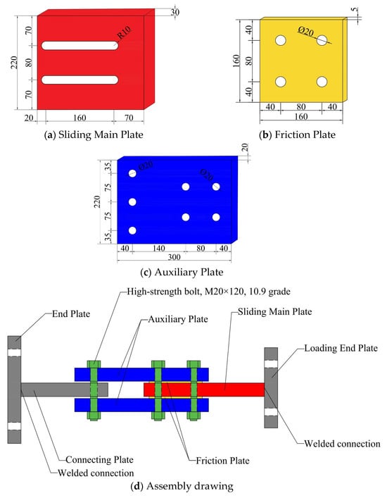
Figure 1.
Dimensions of Each Component of the Friction Damper and the Overall Assembly Drawing.
The sliding main plates are fabricated from Q355B steel. Each plate has a length of 300 mm, a width of 80 mm, and a thickness of 20 mm. Bolt holes (with a diameter of 20.5 mm) are drilled at both ends to match the high-strength bolts, ensuring stable connection and force transmission.
As the core variable component of the damper (material differences are defined in Section 2.2), the friction plates feature a unified geometric size to guarantee consistent contact area across all specimens. Specifically, each friction plate has a length of 160 mm, a width of 80 mm, and a thickness of 15 mm—this uniform design eliminates the interference of geometric differences on friction performance testing.
The auxiliary plates are also made of Q355B steel, sharing the same length (300 mm) and width (80 mm) as the sliding main plates, while their thickness is 15 mm. Their main function is to apply uniform preload to the friction plates through bolts, ensuring the friction interface receives stable and even pressure during the test.
For the high-strength bolt assemblies, 10.9-grade M20 × 120 bolts (compliant with the GB/T 1228-2006 [31] standard) are selected. To prevent preload attenuation during cyclic sliding of the damper, disc springs (meeting the DIN 2093 standard [32]) are installed together with the bolts, which helps maintain the stability of normal pressure on the friction interface throughout the test.
2.1.2. Working Mechanism
The damper operates based on Coulomb’s friction law: the normal pressure on the friction interface is provided by the preload of high-strength bolts, and relative sliding between the sliding main plate and friction plate (driven by external seismic displacement) generates friction force for energy dissipation. Since it is a displacement-dependent device, its energy dissipation effect is minimally affected by sliding speed.
The restoring force model of the damper was fitted using an ideal elastoplastic model, which aligns with the typical mechanical behavior of friction dampers in seismic engineering and ensures the comparability of performance data across different friction plate materials.
2.2. Definition of Specimen Components
To systematically investigate the influence of friction plate materials on the performance of friction dampers, three types of specimens were designed in this study. All specimens maintain identical structural configurations and assembly processes, with the only variable being the material of the friction plates. This design ensures that any differences in damper performance can be directly attributed to the intrinsic properties of the friction plate materials.
The first type of specimen is denoted as S-CO. Its friction plate is made of H68 brass that complies with the GB/T 5231-2012 [33] standard. The sliding main plates and auxiliary plates of the S-CO specimen, consistent with the structural design described in Section 2.1, are both fabricated from Q355B low-alloy high-strength steel (GB/T 1591-2018 [34]). This specimen is intended to characterize the friction behavior and energy dissipation capacity of brass-steel contact pairs under cyclic loading.
The second type, labeled S-CE, employs 3Y-TZP zirconia ceramic as the friction plate material. This ceramic material, stabilized with 3 mol% yttria (), meets the requirements of the GB/T 16536-2022 [35] standard. Similar to the S-CO specimen, the sliding main plates and auxiliary plates of S-CE are constructed from Q355B steel. The S-CE specimen is designed to evaluate the wear resistance and friction stability of ceramic-steel combinations, which are critical for long-term service in engineering applications.
The third type, designated S-T, uses TC4 titanium alloy (Ti-6Al-4V) for its friction plates, adhering to the GB/T 3620.1-2022 [36] standard. Its sliding main plates and auxiliary plates also utilize Q355B steel, maintaining consistency with the other two specimen types. The S-T specimen aims to assess the lightweight advantage of titanium alloys and their friction compatibility with steel, providing data support for applications requiring weight reduction.
By comparing the test results of these three specimens, the study quantitatively analyzes how material properties such as hardness, thermal conductivity, and wear resistance (as detailed in Table 1) affect key performance indicators of the damper, including hysteretic curve shape, energy dissipation coefficient, and cumulative wear.

Table 1.
Table of Material Properties of the Friction Damper.
After receiving the finished components, we assembled the damper in the laboratory. The assembled friction damper is shown in Figure 2.
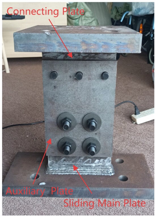
Figure 2.
Physical Diagram of the Friction Damper.
3. Test Design and Test Process
This section aims to investigate the relationship between the torque of the torque wrench and the bolt preload, design the loading scheme for the friction damper, and conduct cyclic loading tests to evaluate its performance.
3.1. Study on the Relationship Between Torque and Bolt Preload
The friction force in the energy-dissipating damper designed in this test is generated by the normal pressure exerted on the friction plates and sliding plates by the upper and lower auxiliary plates. This normal pressure originates from the preload applied by four 10.9-grade M20 high-strength bolts. To ensure the consistency of test results when replacing friction plates, it is crucial to control the bolt preload using a torque wrench. This can minimize pressure-induced variations and eliminate unnecessary interference. Strain gauges are used to monitor the relationship between the torque of the torque wrench and the bolt preload, ensuring that the pressure remains consistent in subsequent tests of different specimens.
The focus of this test is to apply preload to the upper and lower steel plates of the friction damper using four 10.9-grade M20 high-strength bolts. This generates pressure between the components, which produces friction when the sliding steel plates move, thereby achieving frictional energy dissipation. A torque wrench is used to control the preload of the high-strength bolts. In addition, disc springs are installed on the bolts to maintain the preload and prevent a decrease in preload during the frictional sliding of the steel plates.
The torque wrench used in this test is the NGJ340 digital display model, with an accuracy of grade 1 and an error range of ±2.5%. Its maximum torque range is 340 N m. The required maximum torque can be preset. After installing a suitable socket for the high-strength bolt, tighten the bolt. When the buzzer sounds, it indicates that the preset torque has been reached, and tightening should be stopped.
Before applying preload to high-strength bolts using a torque wrench, it is essential to establish the relationship between torque and preload. This enables precise control of the pressure applied to the friction damper during testing. Such a relationship is determined through steel pipe pressure tests. To prevent buckling during the test, Q345 circular hollow steel pipes with an inner diameter of 20 mm, a thickness of 5 mm, and a length of 50 mm are used. Four strain gauges are uniformly placed on each steel pipe, with a total of two test specimens. The DN3816 static strain testing system is employed to measure strain values, which provides the data required for calculating the bolt preload.
During the test, the high-strength bolt passes through the steel pipe, and preload is applied using a torque wrench. Since the screw of the high-strength bolt is 12 cm long, but the thread length is only 4 cm, it is not suitable for the 5 cm length of the steel pipe. Therefore, the bolt first passes through a 4 cm thick steel plate, then the steel pipe is installed, with gaskets placed at both ends. The test procedure is shown in Figure 3.
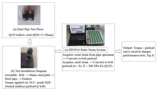
Figure 3.
Torque—Preload Test Workflow for Damper Bolt Specimens.
By fitting the test data, the fitting curves of the torque values of the torque wrench and the preload of the high-strength bolts for the two specimens in the test are shown in Figure 4. It can be seen from the figure that the curves of the torque-preload relationship obtained from the two specimens are almost overlapping. Based on the test results, the relationship between the torque of the torque wrench used in this test and the preload is as follows:
where P-pre-tightening force (kN); T-torque (N·m)
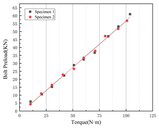
Figure 4.
Calibration curve of the torque wrench.
This test focuses on the relationship between the preload and torque of a single high-strength bolt. However, the friction damper test involves the combined operation of four high-strength bolts. Therefore, in the friction damper test, the preload acting on the friction damper is as follows:
F = 4P
In the friction damper test, the torque applied by the torque wrench is 80 N·m, the preload of the high-strength bolt is 45 kN, and the pressure received by the friction damper is 180.0124 kN.
3.2. Design Concept and Parameter Derivation of the Experimental Loading Scheme
To investigate the hysteretic performance and stability of friction dampers while addressing their practical requirement to withstand multi-level seismic actions in building scenarios, the experimental loading scheme (encompassing displacement amplitudes, cycle counts, and loading rate) was designed to “accurately simulate the working state of dampers under different seismic intensities”. These parameters were determined based on the following logic:
3.2.1. Determination of Displacement Amplitudes and Cycle Counts
Four displacement amplitudes (5 mm, 15 mm, 25 mm, 35 mm) were selected, with a loading pattern specifying 3 cycles for 5 mm, 15 mm, and 25 mm, and 30 cycles for 35 mm. This design aligns with the “minor-moderate-major earthquake” multi-level fortification principle in building seismic design, combined with the actual installation conditions of the friction damper.
For minor and moderate earthquake conditions, building seismic design requires structures to remain elastic under minor earthquakes and enter the elastoplastic stage under moderate earthquakes. For a typical building with a 3 m story height, the inter-story displacement under minor earthquakes (elastic stage) is approximately 5.45 mm, while those under moderate earthquakes (including near-major earthquakes, elastoplastic stage) are 15 mm and 25 mm. Accordingly, 5 mm, 15 mm, and 25 mm amplitudes were chosen to simulate small damper sliding under minor earthquakes and elastoplastic displacement demands under moderate earthquakes. Given that moderate earthquake main shocks typically involve 2–4 significant displacement cycles, 3 cycles were set to cover the damper’s typical operating frequency in this stage, ensuring accurate capture of its hysteretic energy dissipation behavior.
For major earthquake conditions, structures rely on plastic deformation for energy dissipation, with a corresponding inter-story displacement of approximately 60 mm for a 3 m story height. Considering that the relative displacement of damper plates accounts for 50–70% of structural inter-story displacement due to force transmission efficiency after installation, 35 mm amplitude was selected to simulate large-displacement operation under major earthquakes. Additionally, major earthquakes are often followed by aftershocks, requiring dampers to withstand multiple cyclic loads. To evaluate stability, 30 cycles were set to simulate the cumulative effect of main shocks and aftershocks, verifying the performance stability of friction plate materials (titanium alloy, brass, zirconia ceramic) under long-term cyclic loading.
3.2.2. Determination of Loading Rate
A loading rate of 0.2 mm/s was adopted in the displacement-controlled stage, with its selection guided by the damper’s displacement-dependent working mechanism and experimental setup constraints.
This loading rate is consistent with the displacement-dependent working mechanism of the damper—under this mechanism, the energy dissipation effect is minimally affected by the movement speed. When a rate of 0.2 mm/s is adopted, it not only accurately simulates the seismic load cycle path but also clearly captures the hysteretic characteristics of different friction plate materials, which aligns with the core research objective of “comparing the influence of materials on damper performance”. The final loading scheme is presented in Figure 5.
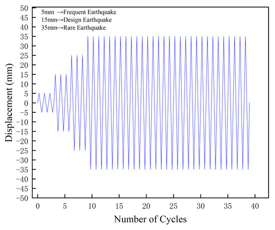
Figure 5.
Cyclic Loading Scheme.
3.3. Process and Results of Friction Damper Loading Test
Due to the different friction plate materials of the selected specimens in the test, the test phenomena of each specimen during operation are different. These three specimens are abbreviated as S-CO (copper-steel plate specimen), S-CE (ceramic-steel plate specimen), and S-T (titanium-steel plate specimen), respectively. The experimental setup is shown in Figure 6. In general, all three specimens produce relatively loud noise during operation. In particular, after the sliding main plate changes the displacement direction, the friction sound between metals can be clearly heard. When the S-CO specimen reaches the maximum displacement and changes direction, a relatively loud sound can be heard, accompanied by slight vibration, and the sound is relatively continuous. The test phenomenon of the S-T specimen is similar to that of the S-CO specimen, and a continuous and uniform friction sound can be heard. However, during the test of the S-CE specimen, the subsequent sound is relatively sharp and discontinuous.
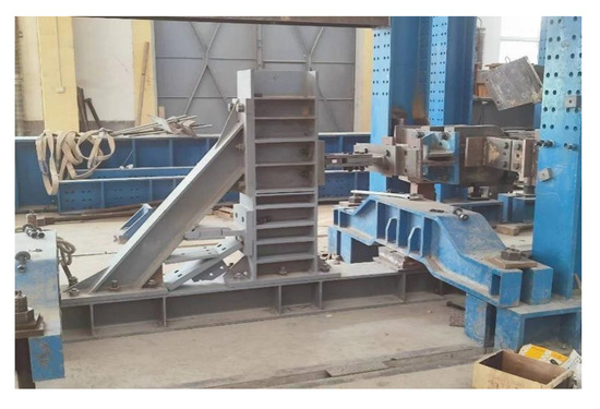
Figure 6.
Physical Diagram of the Loading Device.
To address the high hardness and low toughness of zirconia ceramic (the friction plate material of S-CE), this study specifically designed a “brittle material test protection measure” before the experiment—all judgment conditions are based on traceable test data and visible physical phenomena to ensure reliability. The core logic is: brittle ceramic materials are prone to cumulative damage under cyclic loading, which will lead to sudden changes in friction performance and even material fragmentation; therefore, two conditions for active loading stop were preset: (1) The friction force fluctuation amplitude within the same displacement cycle (calculated from real-time data of the DN3816 static strain testing system) exceeds 20% (a critical indicator of friction interface instability); (2) Visible damage (such as obvious scratches, local spalling, or white ceramic powder) is observed on the friction plate surface during loading. During the test of the S-CE specimen, when the 3rd cycle of 15 mm displacement was completed, real-time monitoring showed that the friction force fluctuated sharply from 95 kN to 130 kN and then fell back to 88 kN, with a fluctuation amplitude of 47.7% (far exceeding the 20% preset threshold); at the same time, obvious longitudinal scratches and white powder were observed on the ceramic friction plate surface. To avoid invalid data caused by further fragmentation of the ceramic plate and potential damage to the Q355B sliding main plate or strain sensors (accuracy ± 1με), we actively stopped the subsequent loading of 25 mm and 35 mm displacements in accordance with the preset protection measure. It is important to emphasize that there was no unexpected interruption during the entire test (e.g., equipment failure, sudden specimen breakage, or data acquisition failure); the active stop was a controllable operation based on objective data and visible phenomena.
After the loading of the three specimens is completed, by observing their friction plates, it is found that all three are seriously damaged, and the protective layers are all damaged.
After completing the tests on the three friction damper specimens and unloading the device, data such as the strains of the upper and lower auxiliary plates, the sliding displacement of the main plate, and its strain were successfully collected. In the data processing stage, these values were sorted out to construct the hysteretic curves as shown in Figure 7. In addition, indicators such as the average push-pull force were calculated.
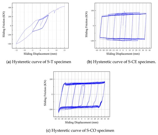
Figure 7.
Hysteretic Curves of the Three Specimens.
4. Comparative Analysis of Three Specimens’ Field Test Data
To study the influence of these three types of friction plates on the energy dissipation capacity and stability of friction dampers, it is necessary to analyze and compare the hysteretic curves of the three specimens, respectively.
As shown in Figure 7, the hysteretic curves of the three specimens from the field tests exhibit distinct characteristics that directly reflect their actual working performance. These curves serve as the core basis for evaluating differences in energy dissipation efficiency and operational stability among the copper-steel, titanium-steel, and ceramic-steel friction pairs, laying the foundation for subsequent quantitative analysis of friction coefficients and wear mechanisms.
The hysteretic curves obtained from the field tests directly reflect the real working states of the three specimens. From these curves, we derived the relationship between the sliding friction force of the main sliding plate and the friction coefficient of the friction material for each specimen, as presented in Table 2. To account for potential inconsistencies in friction force during positive and negative displacement cycles, as well as errors from equipment and specimen manufacturing variations, the average value of the two friction coefficients (calculated for positive and negative directions) was adopted to minimize test errors.
Table 2.
Numerical Table of the Sliding Friction Force of the Sliding Main Plate and the Friction Coefficient of the Friction Material.
4.1. Specimen-Specific Comparative Analysis of Hysteretic Curves
To further reveal the intrinsic links between hysteretic curve characteristics and friction plate material properties as well as test conditions, the following targeted analysis of the three friction pair specimens (titanium-steel, ceramic-steel, copper-steel) is conducted based on field test results:
4.1.1. Titanium-Steel Friction Pair (S-T Specimen)
The hysteretic curve of the S-T specimen (Figure 7a) is generally close to an ideal rectangular shape under most displacement amplitudes, but exhibits two notable features when the displacement reaches 25 mm: slight sliding force fluctuation and positive- negative asymmetry.
Post-test observations (Section 3.3) indicate that the titanium alloy friction plate surface has obvious friction marks: initial rough peaks are worn flat during cyclic sliding, while local protrusions form in later stages due to stress concentration. This dynamic change in surface morphology directly leads to fluctuations in the friction coefficient, resulting in unstable sliding force. In addition, minor alignment deviations of the loading equipment cause uneven stress distribution on the friction interface, further exacerbating the positive-negative asymmetry of the curve.
4.1.2. Ceramic-Steel Friction Pair (S-CE Specimen)
The hysteretic curve of the S-CE specimen (Figure 7b) shows distinct stage characteristics: at small displacements (≤15 mm), the curve is relatively flat and close to a rectangular shape; when displacement exceeds 15 mm, the curve diverges sharply—sliding force increases significantly with displacement, and the positive-negative symmetry of the curve is severely damaged.
The root cause lies in the physical properties of zirconia ceramic: its low thermal conductivity leads to local accumulation of frictional heat during sliding, triggering oxidative wear on the friction surface. The uneven distribution of the oxide layer causes irregular fluctuations in the friction coefficient. Meanwhile, the brittleness of ceramic induces microcracks on the surface under cyclic loading, destroying the uniformity of the friction interface. These two factors together lead to the sharp divergence of the hysteretic curve at large displacements.
4.1.3. Copper-Steel Friction Pair (S-CO Specimen)
Among the three specimens, the hysteretic curve of the S-CO specimen (Figure 7c) maintains the most stable rectangular shape throughout the test. The only deviation is slight force attenuation in the later cycles (after 20 cycles at 35 mm displacement), which is far less obvious than the instability of the S-CE and S-T specimens.
This stability is attributed to the high thermal conductivity of brass: frictional heat generated during sliding diffuses uniformly, avoiding local high-temperature oxidation and ensuring stable surface morphology of the friction plate. However, the overall temperature rise in the interface weakens the interaction force between friction pairs, leading to a slight decrease in the friction coefficient and thus minor force attenuation. Post-test observations also confirm that the protective coating on the brass surface is completely worn away—initial “running-in wear” reduces surface roughness, but this change is phased and mild, so it does not affect the overall stability of the curve.
4.2. Analysis of Hysteretic Curve Characteristics and Energy Dissipation Stability for Different Friction Pairs
It can be seen from the hysteretic curves that the curves of the friction dampers with titanium and copper friction plates are close to the standard “rectangle” and have good energy dissipation capacity, indicating that their energy dissipation performance is relatively stable. Under the same other conditions, the energy dissipation of the damper with titanium friction plates is about 10.43 KJ, and that with copper friction plates is about 18.45 KJ.
The ceramic friction plate showed stable performance in the initial stage, with a gentle hysteretic curve. However, as the sliding displacement increases, the hysteretic curve shows a divergent trend. This may be because under working conditions such as heavy load and high temperature, the ceramic material will release a lot of heat energy during the friction process, accelerating the frictional chemical reaction and converting mechanical wear into oxidative wear. As a result, the surface friction force changes, affecting the friction stability of the friction damper. Notably, the poor stability of the ceramic-steel friction pair (S-CE) is further exacerbated by the coupling effect between the highly polar surface of zirconia ceramics and environmental moisture—an interfacial mechanism rarely considered in previous friction damper studies. Yi et al. [37] systematically revealed through molecular dynamics (MD) simulations and ball-on-disc tribological experiments that polar material surfaces (e.g., hydroxylated , zirconia ceramics) exhibit significantly stronger adsorption capacity for water molecules compared to non-polar metals. Water molecules tend to form stable adsorbed layers on polar surfaces via hydrogen bonding with surface hydroxyl groups; when the local temperature rises due to frictional heat accumulation (local temperature of the ceramic-steel pair in this study may exceed 100 °C), the adsorbed water film undergoes tribochemical reactions with oxidation products on the ceramic surface (e.g., the hydroxylated layer of ). This reaction accelerates the formation and peeling of Si-O-Si network structures, which not only causes abrupt changes in surface roughness but also transforms the friction interface from direct ‘ceramic-steel contact’ to a complex ‘ceramic oxide layer-water film-steel’ contact. Consequently, sliding resistance fluctuates irregularly with water film thickness and oxide distribution, ultimately leading to friction force divergence and the destruction of hysteretic symmetry.
This microscopic mechanism also explains why the stability of the S-CE specimen during 35 mm large-displacement cycles (where frictional heat accumulation is more pronounced) is far inferior to that in small-displacement stages: larger displacements intensify the coupling effect between frictional heat and moisture, triggering more drastic dynamic changes in the interfacial chemical state. The low thermal conductivity of ceramics (240 GPa Young’s modulus, 6100 kg/m3 density; Table 1) further amplifies this local thermal-moisture effect, which aligns perfectly with the experimental phenomenon of the S-CE specimen being ‘stable at small displacements but divergent at large displacements’ in this study.
For the S-T specimen, when the displacement amplitude reaches 25 mm, obvious friction marks appear on the surface, and the friction coefficient increases, resulting in a large friction force on the sliding main plate. In addition, due to equipment errors, slight imbalance between tension and compression is observed. In contrast, the friction of the S-CO specimen is more stable. Under dry friction conditions, the lower the surface roughness, the larger the actual contact area, the greater the adhesive component of friction, and thus the larger the friction coefficient. With the progress of sliding friction, the temperature of the brass surface rises, which weakens the interaction between the friction pairs, reduces the mutual obstruction between rough peaks and the shear resistance at the contact points, leading to a decrease in the friction coefficient. Under the combined influence of these two effects, the friction coefficient first increases with the decrease in surface roughness, and tends to be stable after the surface roughness decreases to a certain extent, thus making the friction stability of the S-CO specimen relatively good.
4.3. Predictive Analysis of Material Performance Under High-Cycle/Whole Service Life Conditions
Based on low-cycle test results (Section 3.3 and Section 4.2), material physical properties (Table 1) and final average friction coefficient data (Table 2), the long-term performance of the three friction pairs under high-cycle conditions (≥100 cycles) and whole service life is predicted.
4.3.1. Copper-Steel Friction Pair (S-CO)
Under high-cycle conditions, the copper-steel pair is expected to undergo running-in within 1–50 cycles, after which the friction coefficient stabilizes around the final average value of 0.399. Its wear rate is predicted to be 0.5–1 μm per 100 cycles, with friction coefficient fluctuation controlled within 5% and energy dissipation attenuation not exceeding 10%.
Over the whole service life, the pair is estimated to withstand 3000–5000 medium earthquake cycles, corresponding to 20–30 years of building service. Regular maintenance every 5 years, such as surface grinding or pre-coating with , can further extend its service life.
4.3.2. Titanium Alloy-Steel Friction Pair (S-T)
For the titanium alloy-steel pair, the dense film on the titanium alloy surface helps maintain a stable friction coefficient under high cycles, with the value expected to stay within 0.213 ± 3%. Its wear rate is predicted to be 0.2–0.4 μm per 100 cycles, approximately 50% of that of the copper-steel pair, and energy dissipation attenuation is controlled within 5%.
The whole service life of this pair is estimated to reach 8000–12,000 cycles, corresponding to 40–60 years of building service. It requires low maintenance, with only bolt preload checks needed every 10 years, and no anti-rust treatment is necessary due to titanium alloy’s corrosion resistance.
4.3.3. Ceramic-Steel Friction Pair (S-CE)
Under high-cycle conditions, the ceramic-steel pair can only maintain stability at small displacements (≤15 mm) and low cycles (≤20 cycles). When displacement exceeds 25 mm, local heat accumulation of ceramics triggers accelerated wear, with the wear rate surging to 5–8 μm per 100 cycles and friction coefficient fluctuation exceeding 30%.
Over the whole service life, this pair is estimated to only withstand 500–800 small-displacement cycles, corresponding to 5–8 years of building service. It is unsuitable for strong earthquake scenarios, and comprehensive microcrack detection is required every 1–2 years.
5. Conclusions and Prospects
5.1. Core Findings
This study tested three friction plate materials (titanium alloy TC4, brass H68, zirconia ceramic) via low-cycle reciprocating load tests to explore their effects on friction damper performance. Results show that brass-steel (S-CO) and titanium-steel (S-T) pairs have hysteretic curves close to ideal rectangles, with symmetric force–displacement relationships and stable energy dissipation. S-CO has the strongest energy dissipation (≈18.45 kJ), while S-T (≈10.43 kJ) maintains comparable stability. Zirconia ceramic-steel (S-CE) only performs stably at small displacements (≤15 mm); larger displacements cause significant friction force divergence, damaging curve symmetry and reducing stability.
The friction coefficient between friction and main plates is critical: S-CE has the highest average coefficient (0.518) but unstable friction due to ceramic oxidative wear. S-CO (0.399) and S-T (0.213) have stable coefficients that stabilize with appropriate surface roughness, ensuring reliable damper operation.
5.2. Engineering Implications
For building seismic protection, brass-steel pairs are recommended for high energy dissipation and cost-effectiveness (e.g., multi-story steel structures). Titanium-steel pairs suit lightweight demands (e.g., large-span structures) due to lower density (4470 kg/m3 vs. brass’s 8920 kg/m3) and stable performance. Ceramic-steel pairs should be avoided in high-intensity seismic or large-displacement scenarios.
In bolt preload control, 10.9-grade M20 bolts require torque wrench calibration per Formula (1), with 80 N·m torque (single-bolt preload ≈45 kN, total ≈180 kN per Formula (2)) and disc springs to prevent preload attenuation. For maintenance, inspect friction surfaces regularly; grind/repair when roughness exceeds 30% of initial value, and apply MoS2; coating to brass-steel pairs to extend service life.
5.3. Research Limitations
This study has certain limitations in the test process and research scope. Affected by the centering deviation of the loading equipment and the connection gap of the specimens, all three specimens have slight tension–compression imbalance; in addition, the friction plates suffered severe wear (with the protective layer completely damaged) after the test, and the impact of wear on the performance attenuation of the damper under long-term cyclic loads was not fully considered. The test only conducted low-cycle reciprocating load tests, without covering the impact of high cycle times (such as more than 100 cycles) and high-temperature environments (where friction heat release may cause local temperature to exceed 100 °C) on material friction performance under extreme seismic scenarios, making it difficult to fully simulate the complex working conditions in actual strong earthquakes. Moreover, only three types of single metal/ceramic materials were explored in the study, without involving new materials such as fiber-reinforced rubber composites (FRRC) and shape memory alloy (SMA) composite friction layers, which limits the reference value for the selection of high-performance friction materials.
5.4. Future Research Directions
To address the existing limitations and further improve the research on friction dampers, future work will focus on several aspects. In terms of error control and specimen optimization, the centering adjustment mechanism of the loading equipment will be optimized, and laser centering technology will be adopted to ensure that the loading direction is consistent with the specimen axis; the specimen connection method (such as adding positioning pins) will be improved to reduce the tension–compression imbalance caused by connection gaps. For long-term performance and extreme working condition research, wear tests under 100–500 high-cycle loads will be conducted to establish a correlation model of “cycle number—wear amount—friction coefficient” and clarify the service life and maintenance cycle of the damper; a high-low temperature environmental chamber (−20~150 °C) will be designed to study the changes in hysteretic performance of the three friction pairs at different temperatures, and a design scheme of temperature-compensated friction dampers with built-in heat dissipation channels or thermal insulation layers will be proposed. In material expansion and performance improvement, the performance of fiber-reinforced composites (FRRC) and SMA-metal composite friction plates will be tested to explore new friction pairs with high energy dissipation, high stability, and long service life; the zirconia ceramic formula (such as doping alumina to improve toughness) will be improved or a metal transition layer will be prepared on the ceramic surface to address the heat release and wear problems of ceramics during friction and enhance their stability under large displacements. Additionally, combined with actual precast concrete frames and steel structures, shaking table tests on the overall structure with friction dampers will be conducted to verify the seismic effect of the damper in real structures and break through the limitations of component-level tests; the engineering design specifications of dampers will be optimized based on test data, and the friction pair selection, bolt preload parameters, and installation acceptance standards for different seismic intensity areas will be clarified.
Author Contributions
Conceptualization, F.J. and C.G.; methodology, F.J.; software, F.J.; validation, F.J., G.X. and J.L.; formal analysis, G.X.; investigation, J.L.; resources, S.D. and Z.I.; data curation, Y.Y.; writing—original draft preparation, F.J. and G.X.; writing—review and editing, F.J. and C.G.; visualization, F.J.; supervision, C.G.; project administration, C.G.; funding acquisition, C.G. All authors have read and agreed to the published version of the manuscript.
Funding
1. China Construction Seventh Engineering Division Installation Engineering Co., Ltd. Application R&D Project of Intelligent Vibration Damping Products, Project No.: 202403137; 2. Shaanxi Provincial Key R&D Program Project: Study on Dynamic Characteristics and Design Theory of New Prefabricated Steel-Concrete Wind Power Tower Drum (Project No.: 2024SF-YBXM-625).
Data Availability Statement
The data that support the findings of this study are available from the corresponding author upon reasonable request.
Conflicts of Interest
The authors declare no conflict of interest.
References
- Pall, A.S.; Marsh, C. Response of Friction Damped Braced Frames. J. Struct. Div. 1982, 108, 1313–1323. [Google Scholar] [CrossRef]
- Aiken, I.D.; Kelly, J.M. Earthquake Simulator Testing and Analytical Studies of Two Energy—Absorbing Systems for Multistory Structures; Report No. UCB/EERC 90/03; University of California: Berkeley, CA, USA, 1990. [Google Scholar]
- Filiatrault, A.; Cherry, S. Seismic Design of Friction Damped Braced Steel Plane Frames by Energy Methods; Report No. UBC/SEEL 88-01; University of British Columbia: Vancouver, BC, Canada, 1988. [Google Scholar]
- Jarrahi, H.; Asadi, A.; Khatibinia, M.; Etedali, S. Optimal design of rotational friction dampers for improving seismic performance of inelastic structures. J. Build. Eng. 2020, 27, 100960. [Google Scholar] [CrossRef]
- Mualla, H.I.; Belev, B. Performance of steel frames with a new friction damper device under earthquake excitation. Eng. Struct. 2002, 24, 365–371. [Google Scholar] [CrossRef]
- Yang, C.; Xie, L.; Li, A.; Liu, B.; He, Y. Experimental study of rotational friction damper for seismic response control: Friction material comparison and configuration optimization. Case Stud. Constr. Mater. 2024, 21, e03825. [Google Scholar] [CrossRef]
- Shi, J.; Zhang, W.; Zhang, C.; Zheng, Y. Development and validation of a hysteretic model for a novel self-centering friction damper. Structures 2024, 64, 106620. [Google Scholar] [CrossRef]
- Li, Y.; Zhang, H.X.; Wang, J.B.; Wang, J.; Yu, H.; Ma, K.; Zhang, X.; Ji, W.; Li, R. Experimental investigation on the seismic behavior of a novel self-centering friction damper. J. Build. Eng. 2023, 76, 107384. [Google Scholar] [CrossRef]
- Qiu, C.X.; Li, J.W.; Jiang, T.Y.; Du, X. Tests of double-stage SMA slip friction damper. Eng. Struct. 2023, 288, 116171. [Google Scholar] [CrossRef]
- Wang, J.; Han, J.; Xu, J. Development of an innovative ring spring-based self-centering friction damper. J. Constr. Steel Res. 2025, 227, 109363. [Google Scholar] [CrossRef]
- Grossi, E.; Zerbin, M.; Aprile, A.; De Risi, R.; De Luca, F. Conceptual study of an innovative friction damper for the seismic retrofit of precast RC structures with poor connections. Structures 2024, 67, 106960. [Google Scholar] [CrossRef]
- Grossi, E.; Aprile, A.; Zerbin, M.; Livieri, P. Preliminary experimental tests of a novel friction damper for seismic retrofit of RC precast structures. Eng. Struct. 2024, 305, 117718. [Google Scholar] [CrossRef]
- Ma, R.; Cheng, Z.; Zhang, X.; Bi, K.; Jiang, S. Mechanical behaviors and seismic performance of a novel rotary amplification friction damper (RAFD): Experimental and analytical studies. J. Constr. Steel Res. 2024, 223, 109051. [Google Scholar] [CrossRef]
- Liu, Y.B.; Jiang, T.; Pang, H.; Dai, J. Design, simulation and energy dissipation evaluating of a new lead shear damper. J. Build. Eng. 2024, 91, 109459. [Google Scholar] [CrossRef]
- Huang, Z.Q.; Huang, W.; Zhang, C.; Yu, T.; Lin, Z.; Lie, W.; Zhao, F. Design and experiment of an innovative rotational two-level friction damper. Eng. Struct. 2024, 308, 118030. [Google Scholar] [CrossRef]
- Lu, Y.J.; Lv, Q.; Liu, Y.; Sun, T.; Yan, H. A friction-strip hybrid damper with multi-phase energy dissipation mechanism: Cyclic test and numerical verification. Thin-Walled Struct. 2024, 200, 111913. [Google Scholar] [CrossRef]
- Ata, A.K.; Yilmaz, C.; Yildirim, C. Analytical and experimental investigation of a motion amplified rotational friction damper. Eng. Struct. 2023, 288, 115987. [Google Scholar] [CrossRef]
- Baraftabi, S.E.; Elizei, H.M.; Esmaeilabadi, R. Numerical and experimental investigation of a new model of friction damper in diagonal brace under cyclic loading. Structures 2024, 61, 105830. [Google Scholar] [CrossRef]
- Zhang, W.X.; Cheng, Z.; Sun, L.J.; Zheng, Y.; Du, X. Experimental study on the dynamic performance of a winding rope fluid viscous damper. Eng. Struct. 2023, 281, 115786. [Google Scholar] [CrossRef]
- Li, D.B.; Zou, Y.; Liu, X.C.; Simpson, B.G.; Xiao, J. Experimental testing of GCr15 bearing steel with different surface treatments as passive friction energy-dissipative shims. Constr. Build. Mater. 2023, 408, 133628. [Google Scholar] [CrossRef]
- Gu, Z.; Liu, W.S.; Wang, W.L.; Qaiser, Z. Investigating the feasibility of a novel asymmetrical friction damper. Mech. Syst. Signal Process. 2024, 208, 110980. [Google Scholar] [CrossRef]
- Gao, J.W.; Wang, C.L.; Meng, S.; Zeng, B. Performance evaluation of friction dampers considering different metal pairs and loading rates. J. Constr. Steel Res. 2023, 204, 107859. [Google Scholar] [CrossRef]
- Shu, Z.; Lu, Z.; Shi, W.; Li, W.; Liu, J.; He, T. Experimental evaluations of friction materials for high performance dual-layer friction dampers with dismountable friction pads. Constr. Build. Mater. 2025, 489, 142351. [Google Scholar] [CrossRef]
- Pellegrino, M.; De Luca, G. Experimental study of sliding friction damper with composite materials for earthquake resistant structures. Eng. Struct. 2021, 248, 113123. [Google Scholar] [CrossRef]
- Wang, X.; Mo, J.; Ouyang, H.; Huang, B.; Lu, X.; Zhou, Z. An investigation of stick-slip oscillation of Mn–Cu damping alloy as a friction material. Tribol. Int. 2020, 146, 106024. [Google Scholar] [CrossRef]
- Li, G.; Cao, S.; Ouyang, X.; Hou, Y. Vibration reduction characteristics of elastic support dry friction dampers in a dual-rotor system under maneuvering flight. Int. J. Non-Linear Mech. 2025, 173, 105041. [Google Scholar] [CrossRef]
- Jiang, M.; Zhang, P.; Gao, X.; Zhu, C. Dynamic characteristics of a complex rotor system supported on active dry friction dampers considering friction-stiffening effects. Int. J. Non-Linear Mech. 2025, 172, 105042. [Google Scholar] [CrossRef]
- Du, H.H.; Wang, Y.D.; Bi, K.; Du, X.; Han, Q. Hysteretic Behavior of a Multifunctional Phased Self-Adaptive Rotational Friction Damper. J. Struct. Eng. 2025, 151, 04025031. [Google Scholar] [CrossRef]
- Wang, J.; Zhou, W. Seismic behavior evaluation of precast self-centering shear walls with replaceable friction dampers through shaking table test. Eng. Struct. 2025, 328, 119711. [Google Scholar] [CrossRef]
- Lee, C.; Ryu, J.; Oh, J.; Yoo, C.-H.; Ju, Y.K. Friction between a new low-steel composite material and milled steel for SAFE Dampers. Eng. Struct. 2016, 122, 279–295. [Google Scholar] [CrossRef]
- GB/T 1228-2006; High-Strength Hexagon Head Bolts for Steel Structures. China Standards Press: Beijing, China, 2006.
- DIN 2093:2013-12; Disc Springs-Quality Specifications-Dimensions. Deutsches Institut für Normung e.V. (DIN): Berlin, Germany, 2013.
- GB/T 5231-2012; Wrought Copper and Copper Alloys-Designations and Chemical Compositions. China Standards Press: Beijing, China, 2012.
- GB/T 1591-2018; Low Alloy High Strength Structural Steels. China Standards Press: Beijing, China, 2018.
- GB/T 16536-2022; Stainless Steel Wire Rods for Welding. China Standards Press: Beijing, China, 2022.
- GB/T 3620.1-2022; Titanium and Titanium Alloys-Part 1: Designations and Chemical Compositions. China Standards Press: Beijing, China, 2022.
- Yi, X.B.; Xu, H.; Jin, G.; Lu, Y.; Chen, B.; Xu, S.; Shi, J.; Fan, X. Boundary slip and lubrication mechanisms of organic friction modifiers with effect of surface moisture. Friction 2024, 12, 1483–1498. [Google Scholar] [CrossRef]
Disclaimer/Publisher’s Note: The statements, opinions and data contained in all publications are solely those of the individual author(s) and contributor(s) and not of MDPI and/or the editor(s). MDPI and/or the editor(s) disclaim responsibility for any injury to people or property resulting from any ideas, methods, instructions or products referred to in the content. |
© 2025 by the authors. Licensee MDPI, Basel, Switzerland. This article is an open access article distributed under the terms and conditions of the Creative Commons Attribution (CC BY) license (https://creativecommons.org/licenses/by/4.0/).