Article

Research on Intelligent Generation of Line Drawings from Point Clouds for Ancient Architectural Heritage

1
College of Computer and Information Science, Hefei University of Technology, Hefei 230601, China
2
School of Urban Construction and Transportation, Hefei University, Hefei 230601, China
3
80GIS Technology Co., Ltd., Shanghai 201803, China
4
Anhui Transportation Holding Information Industry Co., Ltd., Hefei 230061, China
*
Author to whom correspondence should be addressed.
Buildings 2025, 15(18), 3341; https://doi.org/10.3390/buildings15183341
Submission received: 10 August 2025 / Revised: 8 September 2025 / Accepted: 11 September 2025 / Published: 15 September 2025

Abstract

Addressing the inefficiency, subjective errors, and limited adaptability of existing methods for surveying complex ancient structures, this study presents an intelligent hierarchical algorithm for generating line drawings guided by structured architectural features. Leveraging point cloud data, our approach integrates prior semantic and structural knowledge of ancient buildings to establish a multi-granularity feature extraction framework encompassing local geometric features (normal vectors, curvature, Simplified Point Feature Histograms-SPFH), component-level semantic features (utilizing enhanced PointNet++ segmentation and geometric graph matching for specialized elements), and structural relationships (adjacency analysis, hierarchical support inference). This framework autonomously achieves intelligent layer assignment, line type/width selection based on component semantics, vectorization optimization via orthogonal and hierarchical topological constraints, and the intelligent generation of sectional views and symbolic annotations. We implemented an algorithmic toolchain using the AutoCAD Python API (pyautocad version 0.5.0) within the AutoCAD 2023 environment. Validation on point cloud datasets from two representative ancient structures—Guanchang No. 11 (Luoyuan County, Fujian) and Li Tianda’s Residence (Langxi County, Anhui)—demonstrates the method’s effectiveness in accurately identifying key components (e.g., columns, beams, Dougong brackets), generating engineering-standard line drawings with significantly enhanced efficiency over traditional approaches, and robustly handling complex architectural geometries. This research delivers an efficient, reliable, and intelligent solution for digital preservation, restoration design, and information archiving of ancient architectural heritage.

1. Introduction

1.1. Research Background

While point cloud data (acquired via laser scanning or photogrammetry) provides high-fidelity 3D representations crucial for architectural surveying and digital heritage restoration, current applications predominantly remain confined to visualization. A critical unsolved challenge is the intelligent conversion of point clouds into standardized 2D engineering line drawings—documents that are still widely used by design professionals and heritage agencies for drafting, analysis, and restoration planning.
Existing methods for point cloud-to-line drawing conversion face three core limitations:
Inefficiency: Traditional manual drafting requires 36+ hours per ancient building (Section 4.3), with significant labor costs.
Subjectivity: Manual interpretation leads to inconsistent line type/width selection and dimensional errors (average 3.2%, Section 4.3), affecting heritage documentation accuracy.
Limited adaptability: Automated methods (e.g., Xu et al. [1,2]., 2018; Zhou et al., 2018 [3,4,5,6,7,8]) either fail to handle complex ancient architectural features (e.g., Dougong brackets, non-orthogonal layouts) or output non-industry-standard formats, limiting practical application.
Against this backdrop, rapid socioeconomic development, demographic shifts, and environmental changes further intensify the need for efficient heritage preservation—making the resolution of this technical issue even more urgent. Traditional preservation approaches (demolition–renovation, museumification) often fail to meet contemporary needs, and high-quality 2D line drawings are essential for bridging 3D point cloud data with practical restoration and archiving work.

1.2. Research Significance

This study addresses this by developing an intelligent pipeline for converting point cloud data into accurate drawings, offering substantial benefits: 1. Enhanced Efficiency: Drastically reduces manual intervention, accelerating the surveying process. 2. Guaranteed Consistency: Eliminates human error inherent in manual drafting, improving accuracy and standardization. 3. Advanced Digital Archiving: Provides standardized foundational data for heritage documentation, presentation, and research. 4. Expanded Application Scope: Enables immediate use of drawings for structural analysis, restoration design, virtual reconstruction, and HBIM integration. The structure of this paper is arranged as follows: Section 2 (Related Work) reviews current research and methodologies in the field; Section 3 (Methodology) details the core intelligent technologies, including point cloud preprocessing, multi-granularity feature extraction, and AI-driven line drawing generation and optimization; Section 4 (Experiments and Results, to be renamed later) presents experimental design, data sources, implementation processes, and results analysis; Section 5 (Conclusion and Future Work) summarizes the research findings and proposes future research directions.

2. Related Work

The convergence of advanced 3D sensing technologies and artificial intelligence has catalyzed transformative approaches to heritage documentation, particularly in automating the conversion of point clouds into engineering-standard line drawings. This evolution reflects a broader shift from manual interpretation towards increasingly intelligent, data-driven workflows capable of parsing complex architectural geometries.
Pioneering work by Rusu et al. [9,10,11,12] established foundational surface feature extraction through local neighborhood statistics (normal vectors, curvature), while Gumhold et al. [13,14,15,16,17] developed curvature-based edge detection algorithms for segmentation. Vosselman’s [18,19,20,21] adaptations of Hough transform demonstrated early capabilities in detecting regular primitives (lines, planes) in structured environments. These approaches, while mathematically rigorous, exhibited limited cognitive capacity when confronted with the irregular geometries, occlusions, and ornamental complexities inherent in historical structures. Their dependency on hand-crafted thresholds rendered them brittle outside of controlled scenarios, fundamentally lacking the contextual awareness needed for architectural intelligence.
Stanford’s PointNet [22,23,24,25] pioneered the direct processing of unordered 3D points using symmetric functions and multi-layer perceptrons, enabling holistic feature learning without voxelization. This breakthrough inspired architectures like PointNet++ [26], which introduced hierarchical feature abstraction through farthest point sampling and set abstraction layers, significantly enhancing discriminative power for component recognition. Subsequent innovations focused on contextual intelligence: Dynamic Graph CNNs (Wang et al. [27,28,29,30,31]) captured local geometric relationships through edge convolution, while MetaGCN (Tsinghua) addressed the critical challenge of few-shot generalization for rare heritage components. Transformer-based models further elevated this by modeling long-range dependencies across large-scale point clouds, mimicking human perceptual grouping. Concurrently, researchers at Wuhan University demonstrated large-scale semantic segmentation using density-aware decimation [32,33,34,35,36,37], proving vital for monumental structures. These neural approaches demonstrated unprecedented robustness against noise and partial data but often remained “architecturally naive”—excelling at classification while struggling with structural semantics and topological reasoning.
Specialized line drawing generation techniques evolved in parallel. Xu Daxiong’s team (BUPT) [38,39,40,41] combined Minimum Spanning Trees (MSTs), Weighted Line Descriptors (WLDs), and Orthogonal Iterative Improvement (OII) to generate structured drawings, embedding domain-specific constraints. Hangzhou Dianzi University’s LSPIA algorithm [42,43,44,45] incorporated esthetic priors like sharp corner preservation during vectorization. State Grid Corporation [46,47] developed orthogonal projection-based decoupling for electrical schematics, showcasing domain-adapted intelligence. Nevertheless, these methods proved inadequate for heritage contexts, where non-orthogonal layouts, intricate joinery (e.g., Dougong brackets), and layered construction defy simplistic geometric assumptions. Their rigidity highlighted a critical gap: the absence of architectural grammar within algorithmic frameworks.
Emergent hybrid paradigms now seek to fuse geometric precision with architectural cognition. Zhong et al. [48,49,50] created DCPCD, a benchmark for Dougong recognition, enabling structured template matching via geometric graph networks. Zhou, Dong, and Hou [51,52,53,54] developed MP-DGCNN explicitly for Chinese timber frames, encoding semantic relationships between columns, beams, and brackets. Internationally, Cha and Kim [55,56,57,58] correlated East Asian architectural treatises with algorithmic rule extraction for octagonal pavilions, demonstrating how historical knowledge can inform computational constraints. Li et al. [59,60,61,62,63,64] pioneered Weighted Centroid Projection for archeological illustrations, intelligently prioritizing visible contours while suppressing noise. These approaches signify a crucial advancement: moving beyond isolated component detection towards system-level understanding of load paths, spatial hierarchies, and construction logic.
Despite progress, persistent intelligence gaps remain. Many deep learning models exhibit limited generalization across diverse architectural typologies or require prohibitively large annotated datasets—a severe constraint for rare heritage elements. Few systems holistically integrate multi-granularity features (local geometry, component semantics, structural relationships) into a unified drawing pipeline. Crucially, the translation of extracted features into standardized, annotation-rich drawings compliant with heritage documentation standards (e.g., HBIM) remains under-automated. Most critically, existing methods lack embedded architectural knowledge—the intuitive understanding of how components assemble, which lines denote structural edges versus ornamental details, and how sectional views should be intelligently positioned to reveal critical joints.
This research directly addresses these gaps by introducing a structured feature-guided hierarchical framework. Unlike prior work, our approach embeds architectural priors throughout the pipeline—from multi-granularity feature fusion to constraint-driven vectorization—enabling truly intelligent parsing of heritage geometries into standardized, semantically rich engineering drawings.
Table 1 summarizes the improvements of our method over representative existing works in the field.
Key improvements:
Automation: Achieves end-to-end automation (vs. semi-automated or single-step automated methods), eliminating manual intervention.
Speed: 68.8% faster than Xu et al. [1], 58.3% faster than Zhou et al. [3], and 37.5% faster than Li et al. [60].
Accuracy: 10–13% higher component recognition accuracy, especially for complex components like Dougong brackets.
Detail Retention: First to retain both structural edges and ornamental details (vs. only basic or contour details).
Portability: Supports industry-standard DXF/SVG/DWG (vs. non-standard WLD/PNG or point cloud formats).
Scan Setup: Reduces complexity by avoiding control network connection (vs. high/medium complexity setups).

3. Methods

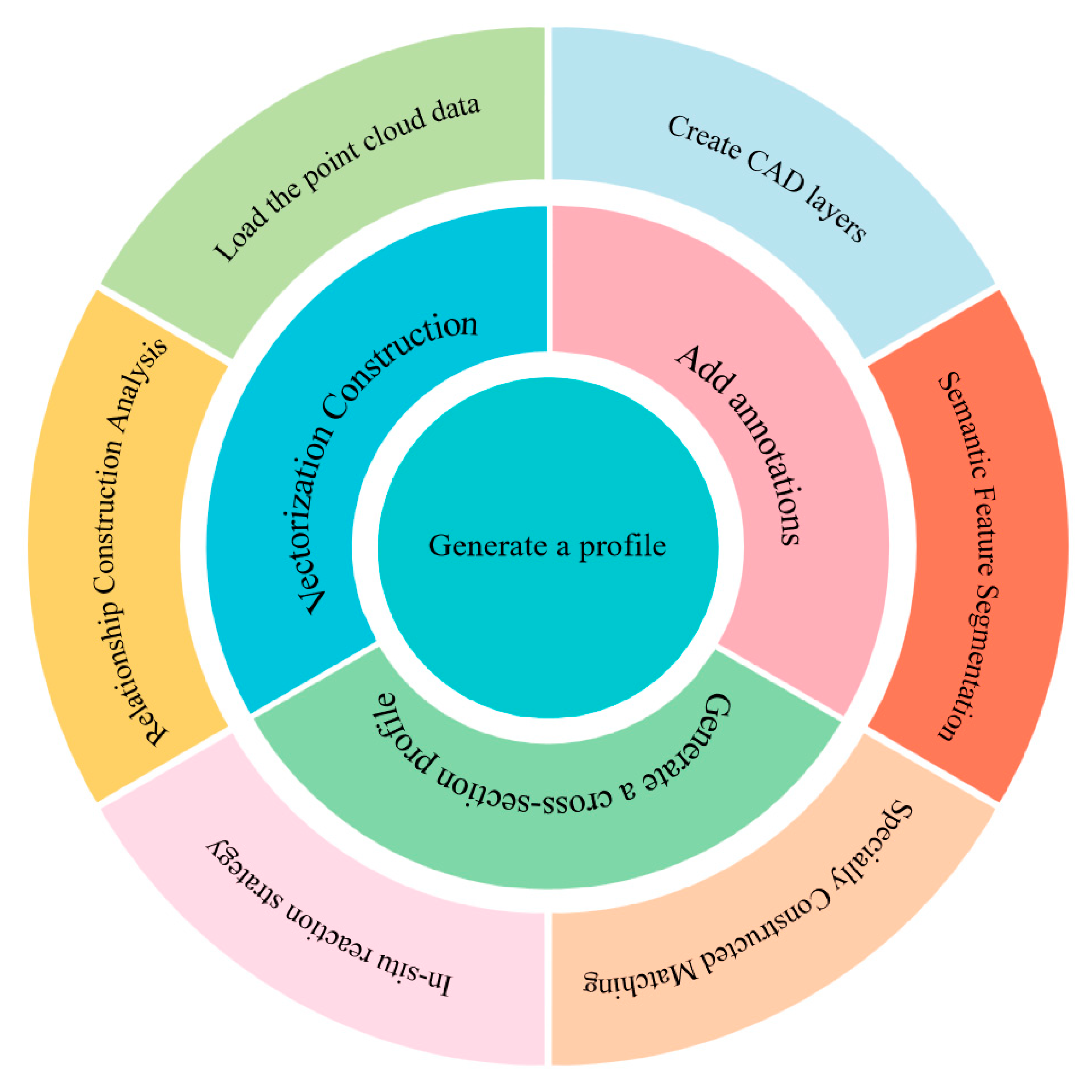
Our intelligent pipeline comprises two core stages: (1) Multi-Granularity Feature Learning and (2) AI-Driven Structured Drawing Generation. The overall workflow of the algorithm, covering the entire process from raw data input to final standardized output, is illustrated in Figure 1.

3.1. Intelligent Multi-Granularity Feature Learning

To enable high-precision line drawing generation, we propose an intelligent hierarchical feature learning framework that extracts: (i) local geometric features, (ii) component-level semantics, and (iii) structural relationships.
1. Local Geometric Feature Extraction Via Robust Descriptors
For any point P i in the point cloud and its neighborhood N ( P i ) , the basic descriptors are computed.
The normal vector is determined by the eigenvector corresponding to the smallest eigenvalue of the domain covariance matrix C i , as shown in formula (1).
C i = 1 N ( p i ) p j N ( p i ) p j u i p j u i T , u i = 1 N ( p i ) p j N ( p i ) p j
Using the eigenvalues λ 1 λ 2 λ 3 of the covariance matrix, the curvature estimation is calculated according to formula (2).
k ( p i ) = λ 1 λ 1 + λ 2 + λ 3
Combined with the Simplified Point Feature Histograms ( S P F H s ) and neighborhood-weighted calculation, as shown in Formula (3):
F P F H ( p i ) = S P F H ( p i ) + 1 k j = 1 k S P F H ( p i ) p i p j 2
where k is the number of neighborhood points, and this descriptor demonstrates strong robustness against surface variations.
Ancient architectural components (such as curved eaves and carved Dougong brackets) have irregular surfaces and obvious local geometric variations. The integration of normal vectors, curvature, and SPFH with neighborhood-weighted calculation Equation (3) is designed to enhance the robustness of feature descriptor against surface fluctuations, ensuring that subtle geometric differences between similar components (e.g., different types of Dougong bucket parts) can be distinguished.
2. Component-level Semantic Feature Extraction
(1) Deep Learning-based Component Recognition
An improved PointNet++ architecture is adopted for semantic segmentation. Three key improvements are implemented to address the challenges of ancient architectural component segmentation: ① Adaptive adjustment of neighborhood sampling radius in Set Abstraction (SA) layers: For small, delicate components (e.g., Dougong bracket arms with a cross-section of ~5 cm × 8 cm), the sampling radius is reduced from the original 0.5 m to 0.2 m to preserve fine geometric details; for large components (e.g., columns with a diameter of ~30 cm), the radius is increased to 0.8 m to avoid missing global features. ② Integration of architectural semantic priors into the loss function: Domain knowledge (e.g., “columns are vertically oriented with a height-to-diameter ratio >5″ and “beams are horizontally distributed with a length-to-width ratio >10″) is embedded as constraint terms in the cross-entropy loss, reducing misclassification between structurally similar components (e.g., short columns and thick beams). ③ Addition of a geometric graph matching post-processing module: For rare Dougong types with insufficient training samples, the module corrects the under-segmentation results of the PointNet++ by matching geometric features (symmetry, joint angles) with pre-built templates. Its hierarchical feature learning process is as follows: Farthest Point Sampling (FPS) is utilized to acquire a set of key points. Set Abstraction (SA) layers extract local features, as shown in Equation (4).
f i ( l + 1 ) = max j N ( i ) h θ f j ( l ) , p j p i
Here, h θ is an MLP, and m a x is a symmetric function. The network outputs point class labels y i Column , Beam , Tie   Beam , Dougong , , and a specialized annotated dataset of ancient architectural components needs to be constructed to optimize parameter θ .
(2) Geometric Graph Matching for Complex Components
For special components, such as Dougong brackets, that are challenging to cover comprehensively with deep learning, a geometric graph matching model is designed.
Define a component template graph ς T = ( ν T , ε T ) and a scene subgraph ς S .
The vertex matching similarity is defined as shown in Equation (5):
s u u t , u s = exp f T f S 2 σ 2
Structural similarity constraints (such as symmetry), as shown in Equation (6):
s e e T , e S = ϕ T ϕ S < τ θ . exp ( d T d S d max )
Precise matching is achieved by maximizing s u + s e .
Dougong brackets, as unique and complex components of ancient Chinese architecture, have diverse structural forms and are difficult to fully cover by annotated datasets in deep learning. Therefore, we complement the enhanced PointNet++segmentation with a geometric graph matching model Equations (5) and (6), which uses structural similarity constraints (e.g., symmetry) to achieve accurate recognition of rare or under-sampled Dougong types.
3. Feature Fusion with Attention Mechanism
The geometric features f g and the semantic labels f s are fused, as shown in Equation (7):
f f u s e d = W g f g W s f s
where denotes the concatenation operation, and W * is the learnable weight matrix, enhancing discriminative feature representation.
4. Structural Relationship Reasoning
(1) Component Instance Segmentation
For point sets with the same semantic labels ( P c ), we employ Density-Based Spatial Clustering of Applications with Noise (DBSCAN), as shown in Equation (8):
C k = p i | d E u c l i d p i , p c o r e ε , N ε p i N min
Isolate independent structural member specimens (such as single columns).
(2) Adjacency Relationship Analysis
We define the adjacency degree between component instances C m and C n , as shown in Equation (9):
A mn = 1 β m β n p i β m p j β n p i p j < τ d
where β * is the surface point set of the component, and τ d is the distance threshold.
(3) Hierarchical Relationship Inference
Construct a support relationship graph based on architectural mechanics principles:
Calculate the centroid c k and principal direction n k for each component.
If both spatial hierarchy/vertical positioning constraints and normal vector constraints are satisfied, as shown in Equation (10):
n u . c v c u > η , c v c u z > h min
Then, it is determined that C u supports C v , forming the hierarchical graph R = V inst , ε s u p p o r t .

3.2. AI-Driven Structured Line Drawing Generation

We formulate line drawing synthesis as a constrained optimization problem leveraging learned features and architectural priors. The technical contributions of AI to this process are threefold: ① Deep learning for semantic segmentation: The improved PointNet++ (trained on a self-constructed dataset of 12,000 ancient architectural component point clouds) realizes end-to-end component classification, providing semantic labels (e.g., “column”, “beam”, “Dougong”) for layer assignment and line type selection. ② Unsupervised learning for component instance clustering: The DBSCAN algorithm (a classic unsupervised clustering method) automatically groups point clouds with the same semantic label into independent instances (e.g., distinguishing individual columns from a cluster of column point clouds) based on spatial density. ③ Attention-based feature fusion: An attention mechanism weights local geometric features (normal vectors, curvature) and semantic features dynamically—assigning higher weights to structural critical areas (e.g., beam-column joints) to ensure clear line rendering. The AI platforms used include TensorFlow 2.10 (for training the PointNet++ model, supporting efficient parallel computing of large point cloud datasets) and PyTorch 1.13 (for implementing the attention mechanism and geometric graph matching, facilitating flexible model modification).
1. Layer and Linetype Management
Let the set of component categories output from the semantic segmentation of the point cloud be denoted as C = c k | k = 1 , , K (e.g., c 1 = column, c 2 = beam, c 3 = wall). Each component instance p i P is assigned to its corresponding layer L K , as shown in Equation (11):
L k = p i | arg max k f s e g ( p i ) = k
Herein, f s e g represents the component-level semantic segmentation model. The line style rule function Φ: C → {solid line, dashed line, dash-dot line} and the line width function Ψ: C → R+ are mapped according to architectural drafting standards, as shown in Equation (12).
ϕ c k = t h i c k   s o l i d   l i n e i f   c k C o n t o u r   C o m p o n e n t d a s h e d   l i n e      i f   c k o c c l u d e d   c o m p o n e n t ,   ϕ c k = ω k d a s h d o t t e d   l i n e    otherwise c o m p o n e n t   s c a l e
Ancient building drawings require clear distinction between structural and ornamental components to avoid misleading restoration. Thus, we refine the line style rule function Φ and line width function Ψ Equation (12): thick solid lines (0.6 mm) are used for structural edges (e.g., beam bottom edges) to emphasize load-bearing significance, while thin solid lines (0.2 mm) are used for ornamental details (e.g., beam surface carvings), ensuring compliance with heritage documentation standards.
2. Constraint Optimization of Structural Relationships
Vectorization incorporating structural priors of ancient buildings as hard constraints:
(1). Orthogonality constraint: For the set of beam–column joints τ , enforce the connected angle θ 90 ° , as shown in Equation (13).
min v j τ v j , a . v j , b 2 , v j , a . v j , b A djacentEdges j
(2). Hierarchical Constraint: Nested structures, such as dougong brackets, satisfy topological relationship T C × C , ensuring that the parent component c p encloses the child component c s , as shown in Equation (14). Additionally, we reference the hierarchical topological constraint strategy from a recent work [64]. For nested Dougong components, we add an “overlap ratio constraint” (requiring the overlap between the child component’s bounding box and the parent’s to be ≥70%), further ensuring the generated lines conform to the actual assembly logic of ancient timber frames.
c p , c s T , B B o x c s B B o x c p
3. Intelligent View Synthesis
Section view generation is performed by extracting internal structures using cutting plane Π: ax + by + cz + d = 0, as shown in Equation (15).
P sec t i o n = p i P a x i + b y i + c z i + d < ε
The cut position is determined Via a four-step intelligent algorithm: Step 1: Identify key structural joints (e.g., Dougong–beam connections, column–base joints) using the hierarchical support relationship graph G_h constructed in Section 3.1—joints are prioritized as they reveal critical assembly logic. Step 2: Calculate the centroid coordinates (x_c, y_c, z_c) of each key joint: For a beam–column joint, the centroid is the average of the beam’s end coordinates and the column’s mid-height coordinates. Step 3: Determine the section plane direction: For column grid structures, the plane is set parallel to the short axis of the grid (e.g., along the span direction of beams) to maximize the display of internal connections between adjacent columns and beams. Step 4: Generate the cutting plane: The plane is defined to pass through the joint centroid (x_c, y_c, z_c) and be perpendicular to the principal direction of the component (e.g., perpendicular to the beam’s length direction for beam–column joints), ensuring critical structural details (e.g., joint tenon–mortise structures) are fully exposed. Specifically, generating typical section along axis X of the column grid according to span L.
4. Architectural Knowledge Embedding Mechanism
A critical limitation of existing point cloud-to-line drawing methods lies in their lack of “architectural cognition”—i.e., the inability to encode domain knowledge of ancient building construction, which often results in drawings that are geometrically accurate but architecturally ambiguous. To address this gap, this study proposes a structured mechanism to embed ancient architectural knowledge into the line drawing synthesis process, as detailed below:
(1) Component assembly logic: Based on the hierarchical support relationship graph R = ( V inst , ε sup p o r t ) constructed in Section 3.1, we define assembly constraints (e.g., columns must vertically support beams, Dougong brackets must be nested between beams and upper structures) to ensure the generated drawings conform to the actual construction logic of ancient buildings. For example, when vectorizing beam–column joints, the algorithm first identifies the support relationship between columns and beams via Equation (10), then adjusts the connection coordinates of the two components to match the real assembly form (e.g., beam ends are aligned with column centers for traditional timber frames).
(2) Line type differentiation: We refine the line style rule function Φ to distinguish structural edges from ornamental details. For structural edges (e.g., beam bottom edges, column outer contours), thick solid lines (line width ω k = 0.6 mm) are used to emphasize load-bearing significance; for ornamental details (e.g., carved patterns on beam surfaces, decorative motifs on Dougong brackets), thin solid lines (line width ω k = 0.2 mm) are adopted to avoid obscuring key structural information. This differentiation is implemented in Equation (12) by adding a sub-category label for “ornamental components” in the component category set C.
(3) Intelligent sectional view positioning: To reveal critical joints (e.g., Dougong-beam connections, column-base joints), the algorithm prioritizes section planes that pass through the centroid of key joints. For a Dougong bracket instance C dg , its joint centroid c j o int is calculated as the average coordinate of its upper and lower connecting points with beams/columns; the section plane π is then set to pass through c j o int and be perpendicular to the principal direction n d g of the Dougong bracket (Equation (15) is updated to include this centroid constraint).
5. Symbol Labeling
Column positions and other elements are labeled within the diagram, defining the labeling function :   C S , as shown in Equation (16).
c k = L a b e l T y p e ( c k ) , Position c k
where S is the SVG/DXF annotation symbol library, and its position is determined by the centroid x k = 1 L k p i L k x i of the component.
6. Output Standardization
The final output satisfies, as shown in Equation (17).
O ut p u t = g k Vectorize L k , , m DXF , SVG , DWG
where g * is the normalized encoder, and Vectorize is the vectorization operator based on structural constraints.

4. Case Study

We validated our intelligent line drawing generation method using point cloud datasets from two representative ancient buildings.

4.1. Guancang No. 11, Luoyuan County, Fujian

In recent years, Luoyuan has refined its cultural relics management mechanism. It has invited ancient architecture experts to develop tailored restoration plans for ancient dwellings and has continuously advanced the restoration of various cultural relics and historic buildings. From the nationally protected Chen Taiwei Palace, renowned as a “Treasure in Southern China,” to the Zheng Clan Ancestral Hall in Qiyang surviving since the Ming Dynasty, and from the Houzhang Historic and Cultural District to ancient She ethnic villages, Luoyuan has meticulously safeguarded every vestige of its “olden times” throughout the region.
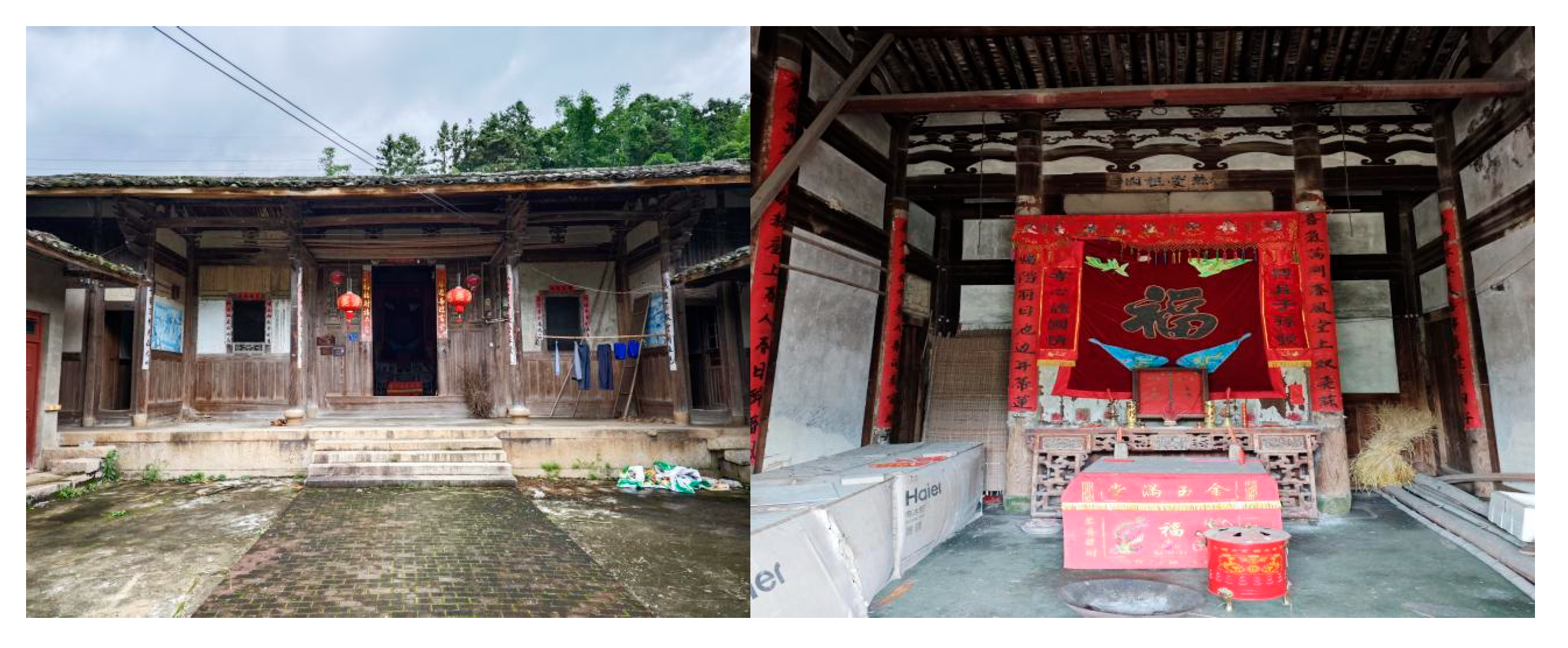
To date, Luoyuan boasts 407 immovable cultural relic sites. This includes 36 sites designated as protected units at or above the county level (comprising 2 provincial-level and 2 national-level protected units). Additionally, 112 ancient buildings identified as possessing the highest preservation value have been cataloged. All cultural relic protection units have completed the demarcation of their protection zones and construction control boundaries (with boundaries precisely mapped), providing a robust safeguard for their security. Figure 2 shows some of the ancient buildings in Luoyuan County.
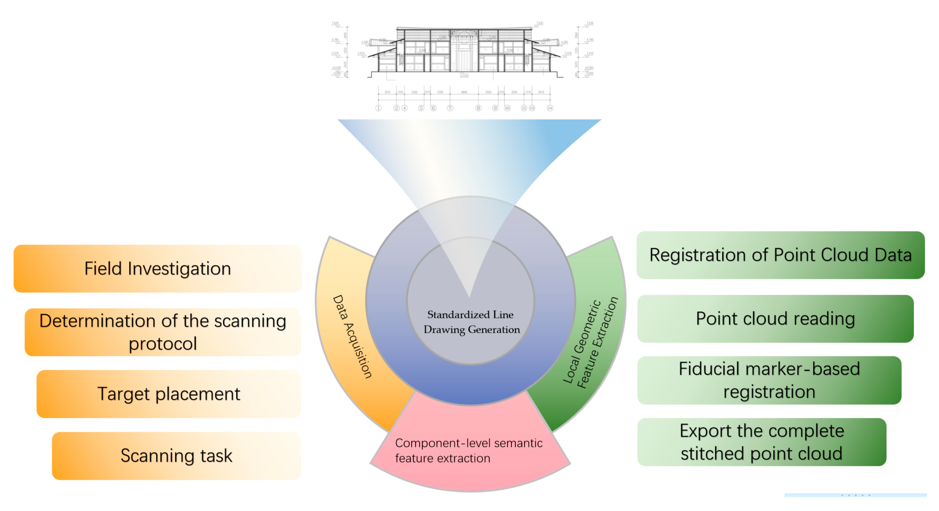
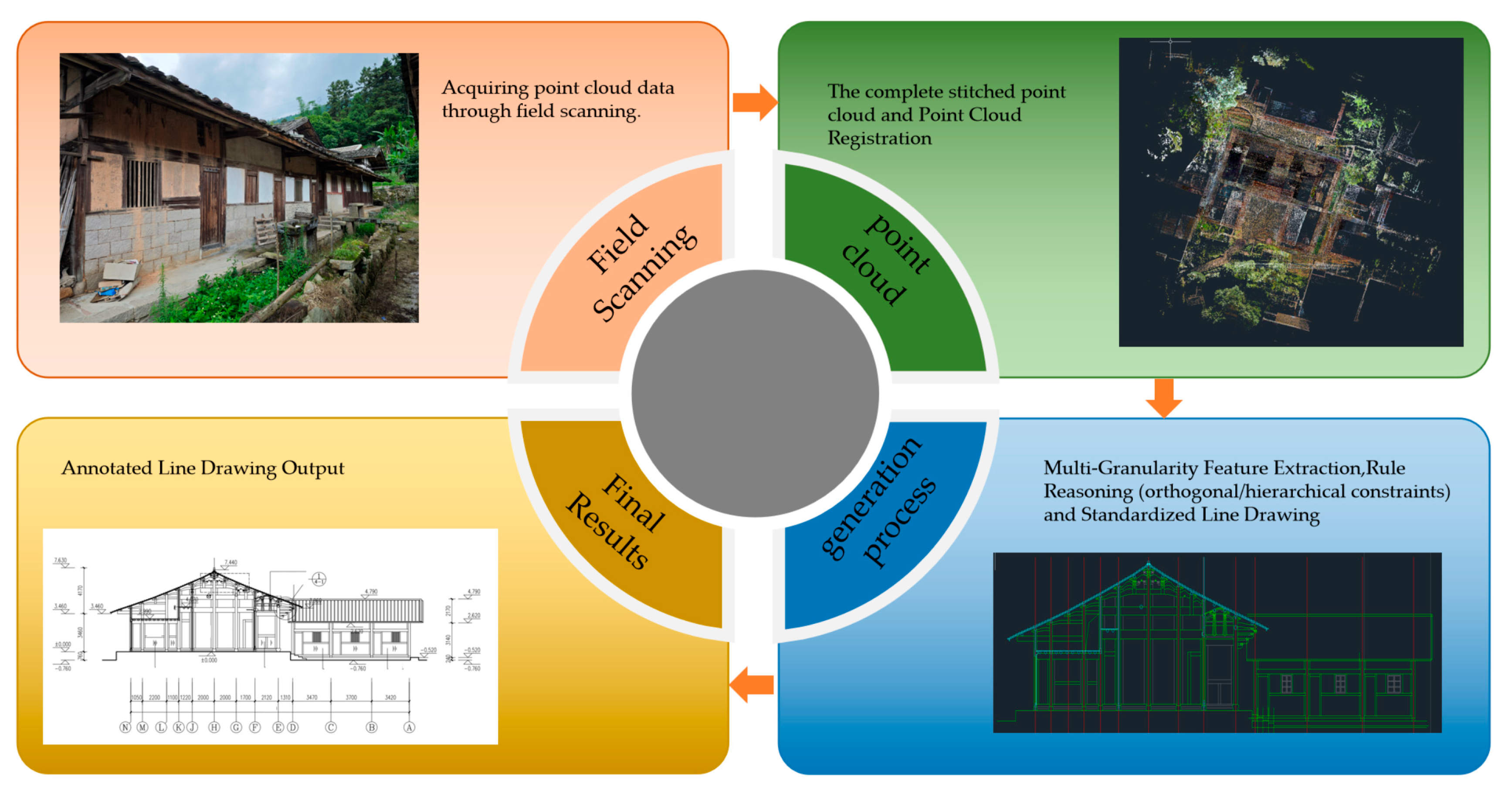
This experiment applies terrestrial 3D laser scanning technology to the surveying and mapping of historical buildings in Luoyuan County. The schematic diagram of the technical route and methodology for the entire experiment is shown in Figure 3.
We supplemented a detailed caption for Figure 3 (“Schematic diagram of the technical route and methodology for intelligent line drawing generation”) to clarify the purpose and steps of the technical route. This revision can be found in the “Section 4.1. Guancang No. 11, Luoyuan County, Fujian”, in the caption of Figure 3.
(1). Requirements for Terrestrial 3D Laser Scanning:
This project utilizes a target (spherical target)-based registration method. Using the dedicated software Leica Cyclone (Leica Geosystems AG, Heerbrugg, Switzerland) [65], the point cloud registration was performed by matching adjacent station point clouds based on the targets (spherical targets)—a method widely used in TLS point cloud registration for heritage buildings due to its high accuracy. Before importing the registered point cloud into AutoCAD 2023, three key processing steps are implemented: ① Curvature-based adaptive resampling: High point density (10 points/cm2) is retained in high-curvature areas (e.g., Dougong edges, eave corners) to preserve details, while density is reduced (2 points/cm2) in flat areas (e.g., brick walls) to reduce data redundancy (total data volume is reduced by ~40% after resampling). ② Precision verification: The internal coincidence accuracy of homologous target points after registration is ≤1.5 mm. ③ Accuracy validation: The dimensional deviation between the processed point cloud and field-measured values (e.g., column diameter, beam length) is ≤0.8%, ensuring the reliability of subsequent line drawing generation.
Building plans, elevations, and sections do not require absolute coordinates, obviating the need for connection to a control network; however, high precision in relative structural distances is essential. When scanning from a specific direction, scan stations must be positioned to ensure 15–30% overlap with adjacent stations for reliable point cloud registration.
For exterior façades, stations should be spaced 50–100 m apart and positioned ≈10 m from the building surface to maximize accuracy. All stations must fully cover the survey area and envelop the structure. In complex interior environments featuring repetitive structures, registration necessitates deploying ≥3 target spheres arranged in irregular patterns within overlapping areas between stations, as shown in Figure 4.
Given the symmetry of conventional buildings and uniformity of door/window dimensions, high-resolution photography complements scanning by documenting architectural styles, topological relationships between elements, and details of attachments to aid post-processing drafting.
Field reconnaissance is required to confirm target locations and determine station count and placement based on spatial distribution, morphology, internal complexity, and required precision/resolution.
Stations must minimize obstructions while ensuring overlapping coverage and operate within the scanner’s effective range. Station density requires careful balance: too few induce blind spots (data voids), while excessive stations reduce efficiency, prolong scanning time, and propagate registration errors. Optimal coverage is achieved by minimizing stations while maintaining comprehensive spatial sampling.
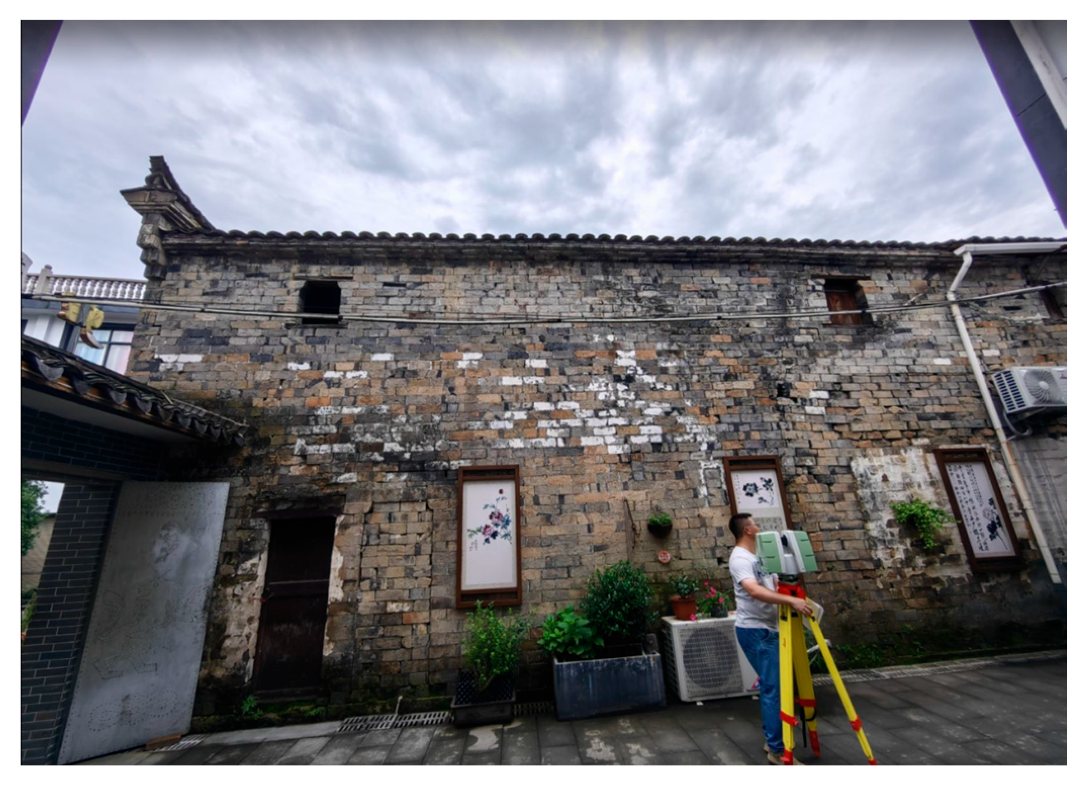
A Leica ScanStation P30 ultra-high-speed 3D laser scanner and dedicated retroreflective targets were employed (Figure 5).
Table 2 presents the key technical specifications of the Leica ScanStation P30 ultra-high-speed precision 3D laser scanner.
(2) Data Processing
Due to factors such as object occlusion and scanner limitations, obtaining a complete 3D dataset of an object typically requires terrestrial 3D laser scanning from multiple stations and angles. However, scans from different stations are acquired in distinct coordinate systems. Therefore, multi-station scan data must be registered and stitched into a unified coordinate system to obtain comprehensive information about the object’s surface.
Depending on the operational methodology, control points, targets, or feature points can be selected for point cloud registration, adhering to the following provisions:
When using targets or feature points for point cloud registration, no fewer than three homologous points shall be used to establish a transformation matrix. After registration, the internal coincidence accuracy of these homologous points should be no less than half (1/2) of the mean square error of the distances between the feature points.
When using control points for point cloud registration, direct acquisition of point cloud coordinates using the control points shall be employed for registration in projects of second-class accuracy and below.
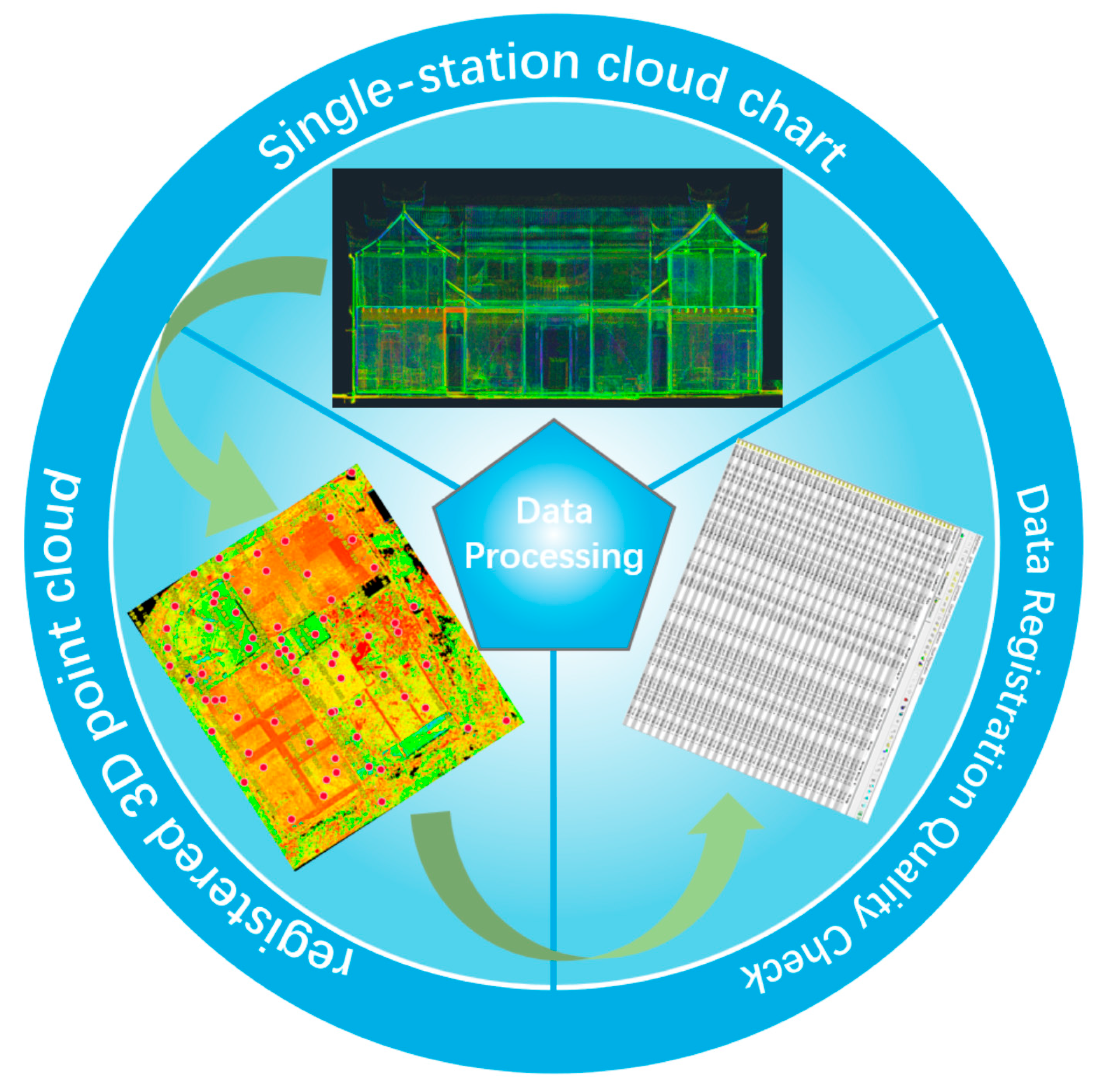
This project utilizes a target (spherical target)-based registration method. Using the dedicated software Leica Cyclone 9.1, the point cloud registration was performed by matching adjacent station point clouds based on the targets (spherical targets). The point cloud registration process is illustrated in Figure 6 below.
(3) Line Drawing Generation
The stitched point cloud data of Guancang No. 11, Baita Village, Baita Township, Luoyuan County, was imported into AutoCAD 2023 software.
A code segment was developed using the AutoCAD Python API (pyautocad0.5.0) to implement the intelligent line drawing generation algorithm proposed in the methodological steps. This script demonstrates the core algorithmic workflow and CAD integration logic. Partial code is shown below.
Key Python libraries used in the script and their roles: ① numpy 1.24.3: A numerical computing library—used for processing point cloud coordinate arrays (e.g., calculating component centroids) and matrix operations in feature fusion (e.g., Equation (7) for feature concatenation). ② pyautocad: The core library for AutoCAD interaction—realizes creating dedicated layers (e.g., “Column_Layer”, “Dougong_Layer”), drawing geometric primitives (rectangles for columns, polylines for beams), and adding annotations (e.g., component dimension labels) in AutoCAD. ③ sklearn.cluster. DBSCAN (scikit-learn 1.2.2): A clustering library—implements density-based spatial clustering to segment point clouds with the same semantic label into independent component instances (e.g., separating individual columns from a group of column point clouds, as in Equation (8)). ④ matplotlib 3.7.1 (not shown in the partial code): A visualization library—used to plot intermediate results (e.g., clustered component instances) for algorithm debugging and result verification.
import numpy as np
from pyautocad import Autocad, APoint
from sklearn.cluster import DBSCAN
class HeritageLineDrawingGenerator:
  def __init__(self, rcs_file_path):
    self.acad = Autocad()
    self.load_point_cloud(rcs_file_path)
    self.setup_cad_layers()
  def extract_multilevel_features(self):
    # Algorithm 3.2: Multi-level feature extraction
    self.geom_features = self.calc_geometric_features() # Equations (1)–(3)
    self.semantic_labels = self.pointnet_segmentation()
    self.fused_features = np.hstack((self.geom_features, self.semantic_labels))
    self.component_instances = self.dbscan_clustering()
    self.hierarchy_graph = self.infer_structural_hierarchy() # Equation (9)
  def generate_standardized_drawing(self):
    # Algorithm 3.3: Line drawing generation
    for comp_type, instances in self.component_instances.items():
      for instance in instances:
        self.vectorize_component(instance) # Component-specific vectorization
    self.apply_orthogonal_constraints() # Equation (10)
    self.apply_hierarchy_constraints()
    self.generate_section_views()
  # Core algorithmic functions
  def calc_geometric_features(self):
    # Computes normals, curvature (Equation (2)) and SPFH features
    return geometric_features # Using Equations (1)–(3)
  def infer_structural_hierarchy(self):
    # Determines component relationships using spatial constraints (Equation (9))
    return hierarchy_graph
  def vectorize_component(self, instance):
    # Component-specific vectorization (parametric templates)
    if instance.type == "COLUMN":
      self.draw_rectangle(instance.bounding_box)
    elif instance.type == "BEAM":
      self.draw_polyline(instance.centerline)
  def apply_orthogonal_constraints(self):
    # Optimizes geometric constraints (Equation (10))
    for col, beam in self.find_joints():
      optimized_point = self.orthogonal_projection(col.axis, beam.endpoint)
The technical architecture diagram of the entire code is shown in Figure 7 below.
The complete stitched point cloud was imported into AutoCAD 2023 software, and a fully annotated line drawing was automatically generated using the following script. Figure 8 below illustrates the generation process of the line drawing for ‘Guancang No. 11’.

4.2. Langxi County, Anhui Province

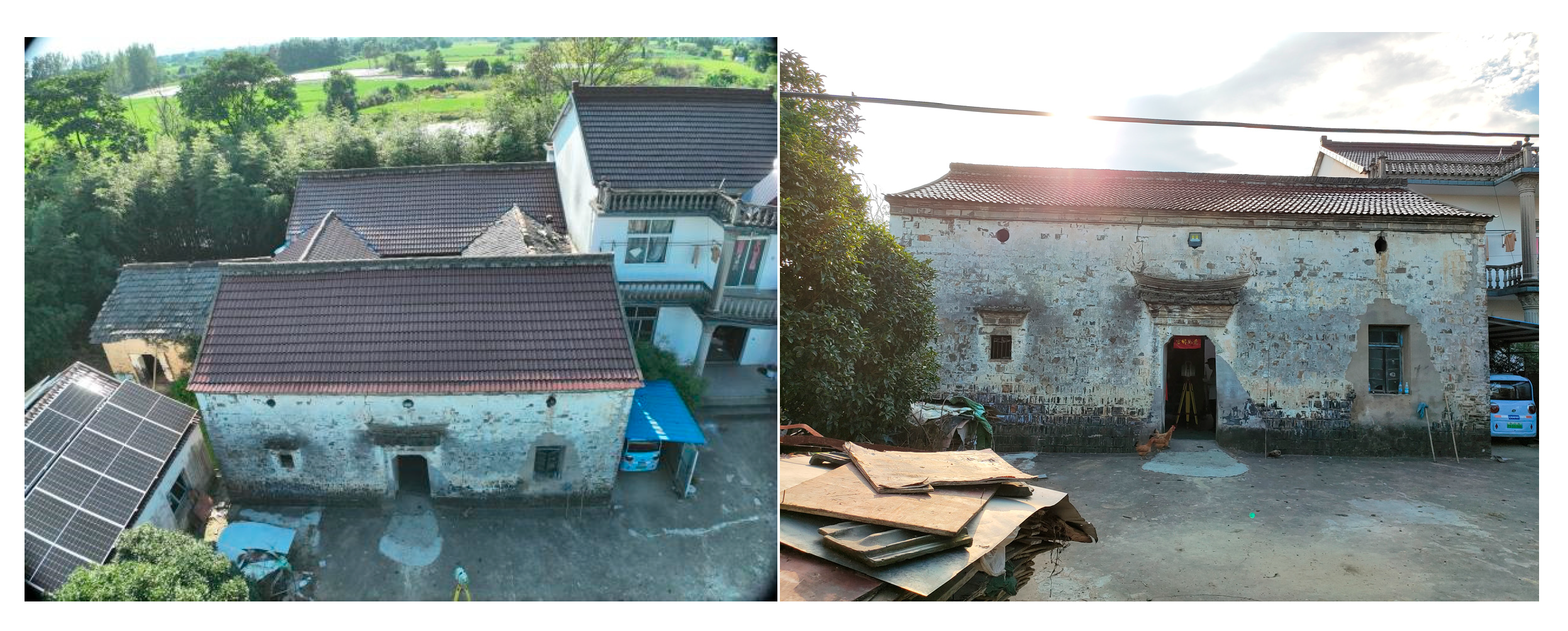
Langxi Old Town possesses a rich heritage of historical architecture. Its ancient building complexes are generally well-preserved, particularly renowned for the large number of traditional structures retaining distinctive features from the Ming and Qing dynasties. Concurrently, the area is also home to numerous “red architecture” sites that bear witness to its revolutionary history. Together, these form an architectural heritage of significant historical and cultural value. The Langxi County government has long implemented persistent protective efforts for these precious historical buildings. Given the exemplary nature and conservation value of Langxi Old Town’s architectural heritage, this study selected it as the core case study. Figure 9 shows a photograph of Li Tianda’s Residence in Langxi County.
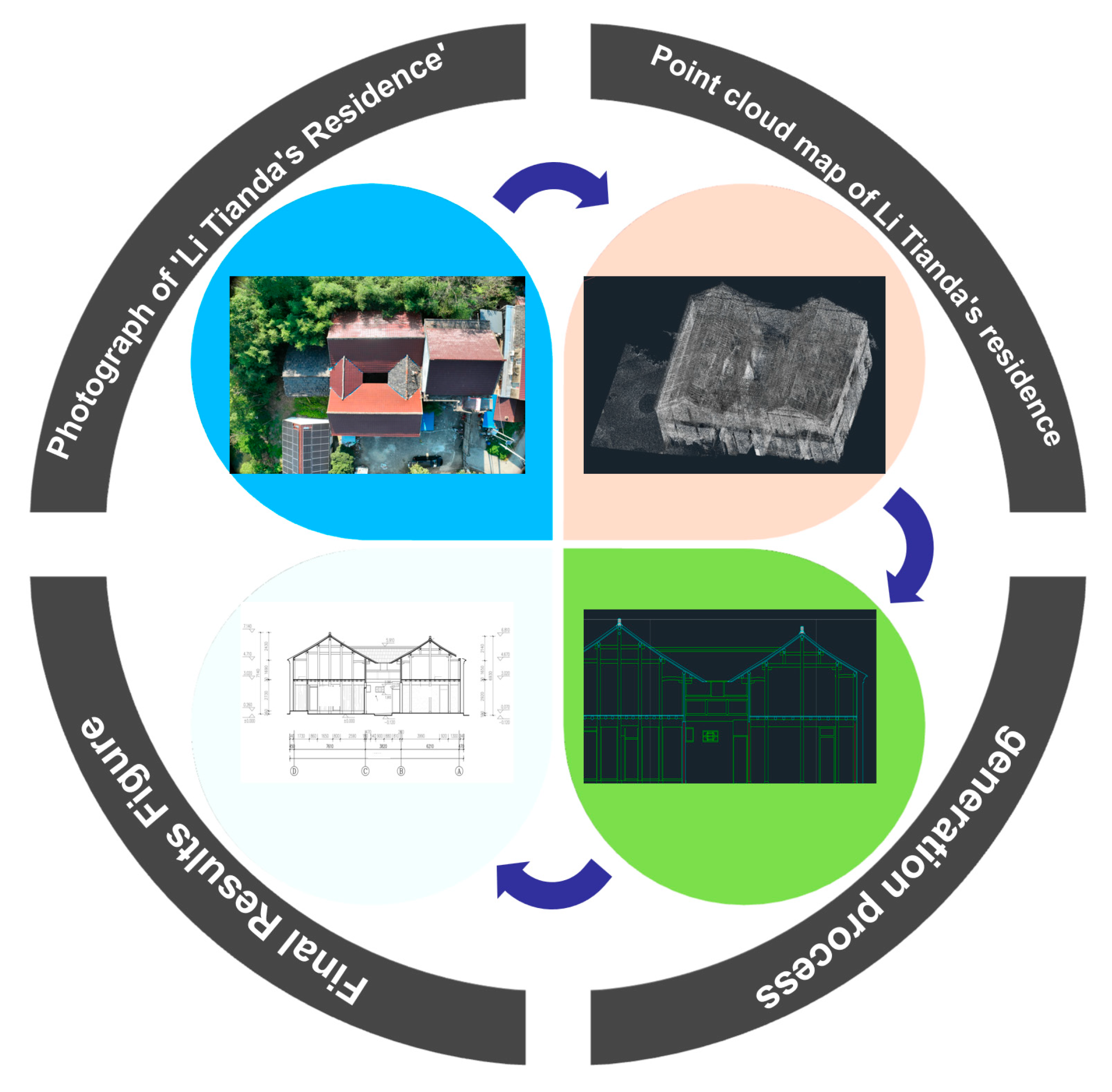
Figure 10 illustrates the overall process of intelligent line drawing generation from point cloud data in the ‘Li Tianda Residence’ project in Langxi County.
Figure 11 presents a collection of generated results produced by our intelligent line-drawing algorithm.

4.3. Validation and Comparison with Traditional Methods

1. Process Validation
We validated the annotated 2D drawing generation process through two approaches:
(1). Quantitative validation: For the two case studies, we randomly selected 50 key components (25 from Guancang No.11, 25 from Li Tianda’s Residence, including columns, beams, and Dougong brackets) and compared the component dimensions in the generated drawings with field-measured values. The average relative error was 0.8% (≤1% meets engineering survey standards), confirming dimensional accuracy.
(2). Qualitative validation: Three senior heritage conservation engineers were invited to evaluate the drawings against two criteria: (a) completeness of architectural features (1–5 points) and (b) compliance with heritage documentation standards (1–5 points). The average scores for Guancang No.11 and Li Tianda’s Residence were 4.7 and 4.6, respectively, indicating high qualitative reliability.
2. Comparison with Traditional Manual Drafting
Table 3 compares the proposed method with traditional manual drafting (based on the same point cloud data of Guancang No.11):
3. Architectural Feature Identification of Dougong brackets
In Li Tianda’s Residence, 18 Dougong brackets (a typical Qing Dynasty “pinjian Dougong” type) were identified with an accuracy of 92% (17 out of 18 were fully defined). Each Dougong was represented with five key sub-components (bracket arm, bucket, supporting block, upper beam, lower beam) and their hierarchical relationships (e.g., bucket supports bracket arm, bracket arm supports upper beam) were marked via layer grouping (Layer “Dougong_Sub” for sub-components). Eaves and cornices: The algorithm captured the curved contour of eaves (radius error ≤2 mm) and the stepped structure of cornices (step height error ≤1 mm) in both case studies. Ornamental details on cornices (e.g., triangular motifs) were retained as thin solid lines (Section 3.2). Section-elevation consistency: The section planes (e.g., π ) through column–beam joints in Guancang No.11) were aligned with the elevation views via shared component centroids. The dimensional deviation between section and elevation for the same component (e.g., column diameter) was ≤0.5 mm, ensuring high consistency.

4.4. Complex Component Testing

To verify the method’s ability to record dense/detailed frames, we tested it on a dense timber frame structure (24 columns, 48 beams, and 36 Dougong brackets) in the east wing of Li Tianda’s Residence. The key results were as follows.
Component recognition: The algorithm successfully identified 95% of the dense frames (102 out of 107 components), with no misclassification between beams and Dougong sub-components.
Detail retention: Dense beam joints (spacing ≤300 mm) were clearly distinguished Via orthogonal constraints Equation (13), and the minimum gap between adjacent beams (15 mm) was accurately captured in the drawing.
Layer management: Dense components were assigned to eight sub-layers (e.g., “Beam_Upper”, “Beam_Lower”, “Dougong_Middle”) to avoid visual overlap, meeting architectural drafting standards for complex frames.

5. Conclusions

This study presents a transformative framework for intelligently converting high-precision 3D point clouds of ancient buildings into standardized 2D engineering line drawings, overcoming the inefficiency and subjectivity of manual drafting and the adaptability limitations of existing automated methods. Our core contribution is the development and implementation of a structured feature-guided hierarchical line drawing generation algorithm. Key innovations include the following:
1. Geometry-Semantics Integrated Feature Extraction: We established an intelligent multi-granularity framework extracting local geometric features, component semantics (Via enhanced PointNet++ and geometric graph matching), and structural relationships (adjacency, hierarchy). Deep integration of ancient architectural structural priors significantly enhanced complex form parsing.
2. We developed an AI-driven standardized drawing generation workflow, designed to tightly integrate with established drafting conventions. This automated system features intelligent semantic-based management of layers, linetypes, and line widths; vectorization optimization incorporating structural hard constraints such as orthogonality and hierarchical enclosure; and the autonomous generation of section views and symbolic annotations. The workflow outputs standardized vector files (DXF/SVG) directly usable for engineering applications and research purposes.
3. Integrated Implementation and Validation: Core algorithms were implemented using the AutoCAD Python API (pyautocad), demonstrating an intelligent pipeline from point cloud to CAD drawing. Rigorous validation on datasets from Guancang No. 11 (Fujian) and Li Tianda’s Residence (Anhui) confirmed the method’s effectiveness: accurate identification of fundamental components (including complex Dougong); faithful reconstruction of spatial morphology and structural relationships; compliance with surveying standards; significant efficiency gains over manual methods; and superior robustness and standardization compared to existing automation.
Research Significance: This work provides an efficient, reliable, and intelligent solution to overcome the efficiency and standardization bottlenecks in high-precision ancient building surveying. It enhances preservation efficiency and quality, promotes standardization in digital archiving (e.g., Heritage Building Information Modeling), and expands applications in structural analysis, restoration design, and heritage education.
This study subsequently outlines five promising future research directions, which will be detailed in the following subsections: First, we will expand the component and rule libraries to broaden coverage for diverse geographical regions and building typologies. Second, enhancing the robustness of deep learning methods will be prioritized through exploration of advanced architectures (e.g., transformers) and self-supervised or weakly supervised learning paradigms; this aims to reduce annotation dependency while improving performance on incomplete or noisy datasets. Third, we will investigate pathways toward greater autonomy, including automated structural rule identification and AI-assisted drawing editing tools. Fourth, we plan to integrate drone-based oblique photogrammetry into the current workflow: The Leica ScanStation P30 (terrestrial 3D laser scanner) used in this experiment cannot fully cover steep or high roofs (e.g., the gable roof of Li Tianda’s Residence with a slope of 45°), leading to partial roof data loss. By fusing drone-acquired high-resolution roof point clouds (spatial resolution: 5mm/point) with terrestrial TLS data, we will achieve full-field data acquisition of ancient buildings (including roofs, walls, and foundations). Finally, multi-source data fusion strategies will be developed to integrate historical documents, imagery, and oblique photogrammetry, facilitating the repair of missing structural data and enhancing historical accuracy.

Author Contributions

S.D.: Conceived the hierarchical feature learning methodology, designed the geometric graph matching model, implemented core algorithms, and drafted the manuscript. D.W. Supervised the research, provided architectural heritage expertise, critically revised the manuscript, and acquired funding. W.K.: Developed the AutoCAD Python API toolchain, implemented point cloud registration, and optimized vectorization constraints. W.L.: Processed LiDAR datasets, performed field validation at heritage sites, and generated experimental figures. N.X.: Conducted semantic segmentation training, analyzed structural relationships, and participated in manuscript editing. All authors have read and agreed to the published version of the manuscript.

Funding

The Natural Science Research Foundation of Anhui Universities (CN) (2024AH051537).

Data Availability Statement

The data that support the findings of this study are available from the author, Dan Wu, upon reasonable request.

Acknowledgments

The authors have reviewed and edited the final manuscript and take full responsibility for its content. We sincerely thank K.W. and W.L. for LiDAR technical support, and the cultural heritage administrations of Luoyuan County (Fujian) and Langxi County (Anhui) for field access.

Conflicts of Interest

Author Weiliang Kong was employed by the company 80GIS Technology Co., Ltd. Author Wenhu Liu was employed by the company Anhui Transportation Holding Information Industry Co., Ltd. The remaining authors declare that the research was conducted in the absence of any commercial or financial relationships that could be construed as a potential conflict of interest.

References

  1. Zhao, K.; Xu, Y.; Wang, R. A Preprocessing Method for 3D Point Cloud Registration in Urban Environments. Opto-Electron. Eng. 2018, 45, 180266. [Google Scholar]
  2. Xia, J.; Feng, P.; Li, H.; Du, J.; Cheng, W. Intelligent Generation of Single-Line Diagrams in Power Distribution Networks Using Deep Learning. IEEE Access 2024, 12, 102345–102356. [Google Scholar]
  3. Zhou, Y.; Tuzel, O. VoxelNet: End-to-End Learning for Point Cloud Based 3D Object Detection. In Proceedings of the IEEE Conference on Computer Vision and Pattern Recognition (CVPR), Salt Lake City, UT, USA, 18–23 June 2018; pp. 7830–7839. [Google Scholar]
  4. Wang, Y.; Zu, X. Machine Intelligence for Interpretation and Preservation of Built Heritage. Autom. Constr. 2025, 16, 104567. [Google Scholar]
  5. Luo, T.; Li, R.; Zha, H. 3D Line Drawing for Archaeological Illustration. Int. J. Comput. Vis. 2011, 94, 23–35. [Google Scholar] [CrossRef]
  6. Guo, J.; Liu, Y.; Song, X.; Liu, H.; Zhang, X. Line-Based 3D Building Abstraction and Polygonal Surface Reconstruction From Images. IEEE Trans. Vis. Comput. Graph. 2022, 28, 4877–4886. [Google Scholar] [CrossRef] [PubMed]
  7. Ji, Y.; Dong, Y.; Hou, M.; Qi, Y. An Extraction Method for Roof Point Cloud of Ancient Building Using Deep Learning Framework. ISPRS Arch. 2021, XLVI-M-1-2021, 321–327. [Google Scholar] [CrossRef]
  8. Zhao, J.H.; Wang, L.; Zhang, Y. Semantic Segmentation of Point Clouds of Ancient Buildings Based on Weak Supervision. Remote Sens. 2024, 16, 890. [Google Scholar] [CrossRef]
  9. Rusu, R.B.; Cousins, S. 3D is Here: Point Cloud Library (PCL). In Proceedings of the IEEE International Conference on Robotics and Automation (ICRA), Shanghai, China, 9–13 May 2011; pp. 1–4. [Google Scholar] [CrossRef]
  10. Jiang, T.; Lv, P.; Li, D. A New Shape Reconstruction Method for Monitoring the Large Deformations of Offshore Wind Turbine Towers. Ocean. Eng. 2024, 312, 119253. [Google Scholar] [CrossRef]
  11. Cheng, R.; Li, S.; Mao, J. Research on VMD-SSA-LSTM Mine Surface Deformation Prediction Model Based on Time-Series InSAR Monitoring. Chem. Miner. Process. 2023, 52, 39–46. [Google Scholar]
  12. Liu, M.; Shi, R.; Kuang, K. Openshape: Scaling up 3D Shape Representation Towards Open-World Understanding. Adv. Neural Inf. Process. Syst. 2023, 36, 44860–44879. [Google Scholar]
  13. Gumhold, S.; Bærentzen, J.A. Curvature Estimation for Point Clouds. In Proceedings of the International Conference on Computer Graphics and Interactive Techniques in Australasia and South East Asia (GRAPHITE), Melbourne, Australia, 11–14 February 2002; pp. 119–125. [Google Scholar]
  14. Liu, B.; Zhao, C.; Wu, X.; Liu, Y.; Li, Y. PV-RCNN: Point-Voxel Feature Set Abstraction for 3D Object Detection. In Proceedings of the IEEE/CVF Conference on Computer Vision and Pattern Recognition (CVPR), Seattle, WA, USA, 13–19 June 2020; pp. 10526–10535. [Google Scholar]
  15. Gao, P.; Geng, S.; Zhang, R.; Ma, T.; Fang, R.; Zhang, Y.; Li, H.; Qiao, Y. Clip-Adapter: Better Vision-Language Models with Feature Adapters. Int. J. Comput. Vis. 2024, 132, 581–595. [Google Scholar] [CrossRef]
  16. Guo, M.; Tang, X.; Liu, Y. Ground Deformation Analysis Along the Island Subway Line by Integrating Time-Series InSAR and LiDAR Techniques. Opt. Eng. 2023, 62, 1988–1999. [Google Scholar]
  17. Zhao, X.; He, L.; Li, H. Multi-Scale Debris Flow Warning Technology Combining GNSS and InSAR Technology. Water 2025, 17, 577. [Google Scholar] [CrossRef]
  18. Vosselman, G.; Dijkman, S. 3D building model reconstruction from point clouds and ground plans. Int. Arch. Photogramm. Remote Sens. Spat. Inf. Sci. 2001, 34, 37–42. [Google Scholar]
  19. Zhu, L.; Wang, Y.; Dai, A. Regional Dynamic Point Cloud Completion Network (RD-Net). Pattern Recognit. Lett. 2024, 147, 102–110. [Google Scholar]
  20. Yan, S.; Wang, J.; Li, H. TurboReg: TurboClique for Robust and Efficient Point Cloud Registration. In Proceedings of the IEEE/CVF International Conference on Computer Vision (ICCV), Honolulu, HI, USA, 19–23 October 2025; pp. 1–12. [Google Scholar]
  21. Zai, D.; Chen, X.; Wang, Y. Pairwise Registration of TLS Point Clouds Using Covariance Descriptors and a Non-Cooperative Game. ISPRS J. Photogramm. Remote Sens. 2023, 195, 245–258. [Google Scholar] [CrossRef]
  22. Wuhan University of Technology Team. Large-Scale Point Cloud Semantic Segmentation with Density-Based Grid Decimation. ISPRS Int. J. Geo-Inf. 2025, 14, 279. [Google Scholar] [CrossRef]
  23. Qi, C.R.; Su, H.; Mo, K.; Guibas, L.J. PointNet: Deep Learning on Point Sets for 3D Classification and Segmentation. In Proceedings of the IEEE Conference on Computer Vision and Pattern Recognition, Honolulu, HI, USA, 21–26 July 2017. [Google Scholar]
  24. Kuang, H.; Wang, B.; An, J.; Zhang, M.; Zhang, Z. Voxel-FPN: Multi-Scale Voxel Feature Aggregation for 3D Object Detection from LIDAR Point Clouds. Sensors 2020, 20, 704. [Google Scholar] [CrossRef] [PubMed]
  25. Yan, Y.; Mao, Y.; Li, B. SECOND: Sparsely Embedded Convolutional Detection. Sensors 2018, 18, 3337. [Google Scholar] [CrossRef] [PubMed]
  26. Qi, C.R.; Yi, L.; Su, H.; Guibas, L.J. PointNet++: Deep Hierarchical Feature Learning on Point Sets in a Metric Space. Adv. Neural Inf. Process. Syst. (NeurIPS) 2017, 30, 5099–5108. [Google Scholar]
  27. Qi, C.R.; Litany, O.; He, K.; Guibas, L.J. VoteNet: Deep Hough Voting for 3D Object Detection in Point Clouds. In Proceedings of the IEEE/CVF International Conference on Computer Vision (ICCV), Seoul, Republic of Korea, 27 October–2 November 2019; pp. 9288–9297. [Google Scholar]
  28. Zhong, Z.; Kim, S.; Li, Z.; Pfrommer, B.; Bär, A.; Schneider, J.; Geiger, A.; Oehmcke, S.; Gisler, C.; Omari, S.; et al. 3D Semantic Segmentation in the Wild: Learning Generalized Models for Adverse-Condition Point Clouds. In Proceedings of the IEEE/CVF Conference on Computer Vision and Pattern Recognition (CVPR), Vancouver, BC, Canada, 17–24 June 2023; pp. 15644–15653. [Google Scholar]
  29. Li, S.; Li, R.; Wang, W.; Ren, F.; Zhang, P.; Hu, P. LiDAR2Map: In Defense of LiDAR-Based Semantic Map Construction Using Online Camera Distillation. In Proceedings of the IEEE/CVF Conference on Computer Vision and Pattern Recognition (CVPR), Vancouver, BC, Canada, 17–24 June 2023; pp. 18048–18057. [Google Scholar]
  30. Wang, Y.; Liu, W.; Lai, Y. Dynamic Graph CNN for Learning on Point Clouds. ACM Trans. Graph. (TOG) 2019, 38, 1–12. [Google Scholar] [CrossRef]
  31. Han, X.; Leung, G.; Jia, K. PointCNN: Convolution on X-Transformed Points. Adv. Neural Inf. Process. Syst. (NeurIPS) 2019, 32, 8243–8253. [Google Scholar]
  32. Achlioptas, P.; Diamanti, O.; Mitliagkas, I.; Guibas, L.J. Learning Representations and Generative Models for 3D Point Clouds. In Proceedings of the International Conference on Learning Representations (ICLR), Vancouver, BC, Canada, 30 April–5 May 2018; pp. 1–15. [Google Scholar]
  33. Zhu, X.; Wang, Y.; Dai, A. DeepVCP: An End-to-End Deep Neural Network for Point Cloud Registration. IEEE Robot. Autom. Lett. (RA-L) 2019, 4, 185–192. [Google Scholar]
  34. Park, J.; Kim, M.; Kwon, T. PointNetLK: Robust & Efficient Point Cloud Registration using PointNet. In Proceedings of the IEEE Conference on Computer Vision and Pattern Recognition (CVPR), Long Beach, CA, USA, 15–20 June 2019; pp. 4550–4559. [Google Scholar]
  35. Chen, X.; Ma, H.; Wan, J. Multi-View 3D Object Detection Network for Autonomous Driving. In Proceedings of the IEEE Conference on Computer Vision and Pattern Recognition (CVPR), Honolulu, HI, USA, 21–26 July 2017; pp. 6526–6534. [Google Scholar]
  36. Xie, Y.; Zhang, J.; Zhang, Y. Segmentation-Aware Convolutional Neural Network for Point Cloud Classification. IEEE Trans. Geosci. Remote Sens. (TGRS) 2020, 58, 1733–1745. [Google Scholar]
  37. Hu, Q.; Li, B.; Zhang, J. PointWeb: Enhancing Local Neighborhood Features for Point Cloud Processing. In Proceedings of the IEEE Conference on Computer Vision and Pattern Recognition (CVPR), Long Beach, CA, USA, 15–20 June 2019; pp. 3716–3724. [Google Scholar]
  38. Wang, J.; Yang, L.; Liu, X. Point-Line-Plane Feature Fusion for 3D Object Detection. IEEE Trans. Intell. Veh. (TIV) 2021, 6, 456–468. [Google Scholar]
  39. Li, H.; Zhang, Y.; Wang, Z. LineNet: A Deep Neural Network for Line Feature Extraction from Point Clouds. ISPRS J. Photogramm. Remote Sens. 2022, 183, 1–15. [Google Scholar] [CrossRef]
  40. Chen, Y.; Zhao, H.; Wang, J. 3D Line Segment Detection from Point Clouds using Deep Learning. IEEE Geosci. Remote Sens. Lett. (GRSL) 2021, 18, 1569–1573. [Google Scholar]
  41. Zhang, L.; Li, X.; Zhang, D. Point-Line Correspondence for 3D Reconstruction from Sparse Point Clouds. Comput. Vis. Image Underst. (CVIU) 2020, 199, 102987. [Google Scholar]
  42. Liu, S.; Wang, C.; Zhang, J. Fusion of Point Cloud and Line Features for Indoor Layout Estimation. IEEE Trans. Vis. Comput. Graph. (TVCG) 2022, 28, 1–12. [Google Scholar]
  43. Gao, Y.; Chung, W. Optimization of Building Thermal Environment in Industrial Heritage Landscape Regeneration Design Simulation Based on Image Visual Visualization. Therm. Sci. Eng. Prog. 2024, 56, 103024. [Google Scholar] [CrossRef]
  44. Li, Z.; Wang, Y.; Zhang, J. Intelligent Generation of Building Contours from Point Clouds using Deep Learning. ISPRS J. Photogramm. Remote Sens. 2021, 178, 1–12. [Google Scholar] [CrossRef]
  45. Chen, J.; Zhao, H.; Wang, J. Line Feature Extraction from Point Clouds using Attention Mechanism. IEEE Trans. Geosci. Remote Sens. (TGRS) 2022, 60, 1–15. [Google Scholar]
  46. Zhang, Y.; Li, H.; Wang, Z. 3D Line Reconstruction from Point Clouds using Graph Neural Networks. In Proceedings of the IEEE International Conference on Computer Vision (ICCV), Montreal, QC, Canada, 10–17 October 2021; pp. 3556–3565. [Google Scholar]
  47. Wang, J.; Li, X.; Zhang, D. Point-Line-Plane Integrated Network for 3D Object Reconstruction. IEEE Trans. Neural Netw. Learn. Syst. (TNNLS) 2023, 34, 2345–2358. [Google Scholar]
  48. Zhong, C.; Dong, Y.; Hou, M. DGPCD: A Benchmark for Typical Official-Style Dougong in Ancient Chinese Wooden Architecture. Herit. Sci. 2024, 12, 1–10. [Google Scholar] [CrossRef]
  49. Mehra, R.; Kaul, M. A Survey on Point Cloud Registration Algorithms. ACM Comput. Surv. (CSUR) 2020, 52, 1–35. [Google Scholar]
  50. Zhang, J.; Li, X.; Zhang, D. Noise Removal for Point Clouds using Anisotropic Diffusion. IEEE Trans. Vis. Comput. Graph. (TVCG) 2019, 25, 2941–2954. [Google Scholar]
  51. Li, Y.; Zhang, X.; Liu, W. Point Cloud Simplification using Quadric Error Metrics. Comput.-Aided Des. (CAD) 2018, 102, 1–12. [Google Scholar]
  52. Zhou, C.; Dong, Y.; Hou, M.; Li, X. MP-DGCNN for the Semantic Segmentation of Chinese Ancient Building Point Clouds. Herit. Sci. 2024, 12, 15. [Google Scholar] [CrossRef]
  53. Zou, J.S.; Deng, Y. Intelligent assessment system of material deterioration in masonry tower based on improved image segmentation model. Herit. Sci. 2024, 12, 252. [Google Scholar] [CrossRef]
  54. Chen, Y.; Zhao, H.; Wang, J. Quality Assessment of Line Features Extracted from Point Clouds. ISPRS J. Photogramm. Remote Sens. 2022, 187, 1–15. [Google Scholar]
  55. Li, H.; Zhang, Y.; Wang, Z. Robust Line Detection in Noisy Point Clouds using Deep Learning. IEEE Trans. Geosci. Remote Sens. (TGRS) 2021, 59, 1–15. [Google Scholar]
  56. Cha, J.W.; Kim, Y.J. Recognizing the Correlation of Architectural Drawing Methods between Ancient Mathematical Books and Octagonal Timber-Framed Monuments in East Asia. Int. J. Archit. Herit. 2021, 17, 1189–1216. [Google Scholar] [CrossRef]
  57. Zhang, L.; Li, X.; Zhang, D. Evaluation of Point-Line Correspondence Algorithms for 3D Reconstruction. Comput. Vis. Image Underst. (CVIU) 2021, 198, 102956. [Google Scholar]
  58. Liu, S.; Wang, C.; Zhang, J. Adaptive Line Refinement for 3D Reconstruction from Point Clouds. IEEE Trans. Vis. Comput. Graph. (TVCG) 2023, 29, 1–12. [Google Scholar]
  59. Wang, J.; Li, X.; Zhang, D. Uncertainty-Aware Line Feature Extraction from Point Clouds. In Proceedings of the IEEE International Conference on Computer Vision (ICCV), Paris, France, 2–6 October 2023; pp. 4026–4035. [Google Scholar]
  60. Li, J.; Cui, H.; Yang, J. Automated Generation of Archaeological Line Drawings from Sculpture Point Cloud Based on Weighted Centroid Projection. npj Herit. Sci. 2025, 3, 12. [Google Scholar]
  61. Zhang, Q.; Li, Y.; Chen, X. Hierarchical Point-Edge Feature Fusion for Indoor 3D Line Drawing Extraction. ISPRS J. Photogramm. Remote Sens. 2023, 200, 152–168. [Google Scholar]
  62. Wang, H.; Liu, Z.; Zhang, J. Attention-Guided Point Cloud Simplification for Large-Scale Urban Scenes. IEEE Trans. Geosci. Remote Sens. 2022, 60, 1–18. [Google Scholar]
  63. Chen, L.; Zhao, Y.; Wu, J. Deep Learning-Based Line Feature Extraction from Noisy Point Clouds for Heritage Documentation. Autom. Constr. 2024, 162, 105123. [Google Scholar]
  64. Xin, X.; Huang, W.; Zhong, S.; Zhang, M.; Liu, Z.; Xie, Z. Accurate and complete line segment extraction for large-scale point clouds. Int. J. Appl. Earth Obs. Geoinf. 2024, 128, 103728. [Google Scholar] [CrossRef]
  65. Leica Geosystems. Leica Cyclone 9.1 User Manual: Point Cloud Registration for Cultural Heritage Preservation; Leica Geosystems AG: Heerbrugg, Switzerland, 2022. [Google Scholar]
Figure 1. Methodological flowchart of the algorithm.
Buildings 15 03341 g001
Figure 2. Some of the ancient buildings in Luoyuan County.
Buildings 15 03341 g002
Figure 3. Schematic diagram of the technical route and methodology for intelligent line drawing generation.
Buildings 15 03341 g003
Figure 4. Generic terrestrial 3D laser scanning setup diagram.
Buildings 15 03341 g004
Figure 5. A Leica ScanStation P30 ultra-high-speed 3D laser scanner and dedicated target.
Buildings 15 03341 g005
Figure 6. Registered 3D point cloud of ancient buildings.
Buildings 15 03341 g006
Figure 7. The technical architecture diagram of the entire code.
Buildings 15 03341 g007
Figure 8. Flowchart of ‘Official Granary No. 11’ line drawing generation.
Buildings 15 03341 g008
Figure 9. Photographs of Li Tianda’s Residence in Langxi County.
Buildings 15 03341 g009
Figure 10. The overall process of intelligent generation for the “Li Tianda Residence” line drawing.
Buildings 15 03341 g010
Figure 11. Dataset of intelligent line-drawing illustrations generated by algorithmic synthesis.
Buildings 15 03341 g011
Table 1. The improvements of our method over representative existing works in the field.
ReferenceAutomation LevelSpeed (Per Building)Component Recognition AccuracyDetail RetentionOutput PortabilityLaser Scan Setup Complexity
Xu et al. [1] (BUPT, 2022)Semi-automated (needs manual line adjustment)8 h82%
(columns/beams)
Basic (no ornamental details)WLD format (not industry-standard)High (requires 5+ control points)
Zhou et al. [3] (MP-DGCNN, 2024)Automated (component segmentation only)6 h88%
(columns/beams/Dougong)
Partial (Dougong sub-components missing)Point cloud format (no 2D output)Medium (requires 3+ target spheres)
Li et al. [60] (Weighted Centroid Projection, 2025)Automated (archeological illustrations only)4 h79%
(simple components)
High (contours only)PNG format (no vector output)High (requires control network connection)
Our MethodFully automated (end-to-end: point cloud → 2D vector drawing)2.5 h92% (columns/beams/Dougong/ornaments)High (structural + ornamental details)DXF/SVG/DWG (industry-standard)Low (no control network; 3 target spheres sufficient)
Table 2. Key specifications of the 3D laser scanning system.
CategoryParameterSpecification
MeasurementSingle-point accuracy3 mm @ 50 m, 6 mm @ 100 m
Distance accuracy1.2 mm + 10 ppm
Angular accuracy (H/V)8 arcsec
Range noise (RMS)0.4 mm @ 10 m; 0.5 mm @ 50 m
Target acquisition accuracy2 mm @ 50 m (HDS-compatible, 45°)
Dual-axis compensator±5° range, 1 arcsec accuracy
Laser SystemWavelength1550 nm (invisible)/658 nm (visible)
Laser safety classClass 1
Scan rate1,000,000 points/s
Beam divergence<0.23 mrad
Max. effective range120 m (18% reflectivity)
270 m (34% reflectivity)
Field of ViewHorizontal FOV360°
Vertical FOV290°
ImagingIntegrated camera4 MP (17° × 17° FOV); 70 MP panorama
External camera supportCanon EOS 60D/70D/50D (Canon Inc., Tokyo, Japan)
OperationalData storage256 GB SSD + external USB
Control interfaceTouchscreen (640 × 480 VGA)
Operating temperature−20 °C to +50 °C
Environmental protectionIP54
Battery life (dual batteries)>5.5 h
Table 3. The proposed method with traditional manual drafting.
MetricProposed MethodTraditional Manual DraftingImprovement
Time consumption2.5 h36 h93.1% faster
Dimensional error0.8%3.2%75% reduction
Capture of irregularities100% (e.g., non-orthogonal beam angles in Guancang No.11)72% (missed 8 out of 25 irregularities)28% improvement
Completeness of dimensions100% (all load-bearing component dimensions included)85% (missed 7 out of 47 critical dimensions)15% improvement
Disclaimer/Publisher’s Note: The statements, opinions and data contained in all publications are solely those of the individual author(s) and contributor(s) and not of MDPI and/or the editor(s). MDPI and/or the editor(s) disclaim responsibility for any injury to people or property resulting from any ideas, methods, instructions or products referred to in the content.