Article

Influence and Bearing Mechanisms of Thorn Shape on Compressive Characteristics of Thorn Piles

1
School of Civil and Environmental Engineering, Changsha University of Science & Technology, Changsha 410114, China
2
Yaha School of Design & Engineering, Haikou University of Economics, Haikou 571127, China
3
School of Civil Engineering, Nanyang Institute of Technology, Nanyang 473004, China
*
Author to whom correspondence should be addressed.
Buildings 2025, 15(18), 3328; https://doi.org/10.3390/buildings15183328
Submission received: 19 June 2025 / Revised: 25 August 2025 / Accepted: 2 September 2025 / Published: 15 September 2025
(This article belongs to the Section Building Structures)

Abstract

A new type of thorn pile is proposed to address the poor bearing capacity of the foundation. The design of five thorn piles is presented, and the numerical simulation of pile–soil interaction under a uniform silt foundation is performed using ABAQUS software. The influence of thorn shape on the compressive bearing capacity of thorn piles is elucidated, and the mechanism of thorn structure on the soil around piles is analyzed. The results showed that the thorn pile can significantly increase pile shaft resistance and reduce pile top settlement compared with the smooth pile. The ultimate bearing capacity of the 5# pile is 1.6 times higher than that of the smooth pile, while the pile top settlement is reduced by 82.9%. The addition of a thorn structure effectively changes the mechanical characteristics of pile shaft resistance softening. Due to the unique characteristic of the divergent conical surface, the truncated conical thorns exert a powerful radial pressure on the surrounding soil under load, thereby increasing the effective stress of the soil around the pile, expanding the influence range of the soil around the pile, and fully mobilizing the shear resistance of the soil, thus improving the bearing capacity of the foundation pile. The optimal shape of the taper thorn is a cone under the same conditions of length and volume. The research results can provide a theoretical foundation for the design and construction of the thorn pile.

1. Introduction

Driven by rapid urbanization, the engineering application of special-shaped piles owing to their high bearing capacity, small settlement, energy saving, and carbon reduction has expanded from traditional high-rise building construction to cutting-edge fields such as cross-sea bridges and automated ports. Piles can be categorized based on the shape of their cross-section into transverse section and longitudinal section piles. Typical types of longitudinal section piles include bamboo joint piles, squeezed branch piles, and screw piles. The compressive bearing capacity of the pile is influenced by the properties of the surrounding soil and the structural form and arrangement of the abnormal section, among which the structural form of the abnormal section structure is the most critical.
At present, researchers at home and abroad have carried out extensive theoretical and experimental investigations on the structural forms of the abnormal part and have achieved significant results. Fu et al. [1,2] and Du et al. [3] designed a multi-toothed pile with a small, modified cross-section, incorporating plain concrete convex structures of different shapes on the side surface of the traditional pile through a hydraulic squeezing and rotating tooth-forming device to solve the bearing behavior reduction caused by mud skin on the pile side. The model test results indicated that the multi-toothed pile exhibited better bearing capacity than the smooth pile. Xiong et al. [4], Fang et al. [5], Guo et al. [6], and Wang et al. [7] designed a new ribbed prestressed bamboo joint pile by symmetrically adding four longitudinal ribs to the outer wall of the traditional bamboo joint pile to connect the circumferential convex ribs. Their research shows that the ultimate bearing capacity of a single pile is increased by more than 15%, and the production cost is reduced by about 10% compared with pipe piles with the same diameter and length. Based on the traditional cast-in-place pile, the squeezed branch pile is constructed by adding several bearing plates or branches at different depths of the pile body via special extrusion and expansion mechanisms, thereby maximizing the pile body end-bearing capacity in order to increase the load-bearing capacity of a single pile [8,9,10]. The extrusion and expansion forms of the device are divided into one-way extrusion and two-way extrusion, corresponding to two geometric bearing plates. Shi et al. [11] analyzed the force characteristics and applicable conditions. They concluded that a one-way extrusion pile is suitable for a compressive pile, whereas a two-way extrusion pile is suitable for an uplift pile. A screw pile is a geometrically optimized deep foundation with continuous threads along its shaft. Its bearing capacity is primarily affected by the structural parameters of threads such as screw spacing [12,13,14], thread width [15,16], and pile outer diameter [17], and there is an optimal screw pitch [18,19]. In recent years, the screw micropiles [20,21,22] and half-screw piles [23,24,25], which are advancements based on screw piles, have gained popularity and been applied in practical projects. The tapered pile is like a wedge wedged into the foundation, making full use of the side of the pile wedge to play the interaction between pile and soil. Wei and El Naggar [26], El Naggar and Wei [27], He [28], and Liu et al. [29] showed that the axial capacity of tapered piles can be effectively enhanced by increasing the side wall inclination angle with an optimal wedge angle range. A step-tapered pile [30,31,32] is a variable cross-section pile characterized by a progressively decreasing pile section with the depth, consistent with the distribution characteristics of axial force along the direction of pile depth. Fang [33] performed indoor model static load tests under vertical load for four types of step-tapered piles with variable diameter ratios and found an optimal variable cross-section ratio of about 0.8. The under-reamed pile [34,35,36,37] is a uniquely shaped pile that expands the pile diameter at the end of the traditional constant section pile, which effectively improves the ultimate tip resistance. Liu et al. [38] and Majumder and Chakraborty [39] examined the impact of the height and angle of the expanded head on the uplift bearing capacity of the under-reamed pile. Their results indicated that increasing the height and angle of the expanded head was beneficial to the improvement of the bearing capacity of the pile foundation.
Inspired by the soil-stabilizing biomechanics of tree roots, discrete and non-continuous convex structures are added to the surface of a thorn pile, which consists of two parts: the pile body and numerous pile thorns. Depending on the different requirements of the project, its shape may be conical, truncated conical, cylindrical, etc. On the one hand, the thorn pile addresses critical limitations of conventional piles, such as sediment-induced axial capacity reduction, inadequate tip resistance in soft ground, and difficulties of entering the rock during installation. On the other hand, the thorn structure can modify soil stress distribution to mitigate the settlement of the pile foundation. It is a technological advancement for pile foundations characterized by a flexible structure, ease of construction, and broad applicability.
Unlike the traditional special-shaped piles, the thorn pile mainly manifests in the following aspects: First, the thorn pile belongs to the mid-bearing pile. The tip resistance of the pile body is enhanced by adding the convex thorn structure, which fully mobilizes the bearing capacity of the pile material and the foundation soil, effectively improving the shaft resistance of the pile. Second, the pile belongs to the discontinuous variable cross-section pile, implying that the force interface of the thorn–soil is discontinuous in the plane of the thorn, and the influence of the horizontal pressure [40] is not considered in the stress process. Third, the convex thorn is geometrically designed to be elongated, and the length can exceed the pile diameter, which makes the influence range of the soil around the pile wider, resulting in the special-shaped effect of the thorn and the long-term performance of the interaction between the pile and the soil different from the traditional special-shaped pile. The prefabricated thorn pile is equipped with a core tube, and the multi-segment sleeve is bolted to the core tube. The pile body can be driven into the soil by static pressure or the hammer method, and then the thorn is pushed out by hydraulic pressure or air pressure. This is a novel pile type enhanced from a standard prefabricated pile, and its construction apparatus has received national patent approval [41,42], as illustrated in Figure 1.
At present, there is little research on thorn piles. Wu and Wu [43], Cao [44], and Gou and Liu [45] have carried out some theoretical research on thorn pile construction technology and forming machine design, laying a foundation for the popularization and application of thorn piles. Yin et al. [46], Dai and Gong [47], Wang et al. [48], and Gong et al. [49] tested the bearing capacity of the root caisson foundation in a practical application. They found that the root caisson foundation was significantly more effective than the standard caisson foundation with the same diameter in improving the bearing capacity and reducing the settlement. In recent years, some scholars have separately investigated the effects of root length [50], number of layers [51], position [52], and interlayer spacing [53] on the vertical bearing capacity of root pile foundation. The research results indicate that the number and position of roots significantly affect the ultimate bearing capacity. Liu et al. [54] and Ji et al. [55] respectively used tests and numerical simulations to explore the impact of horizontal arrangement patterns of roots on the bearing capacity of root pile foundations. The results showed that compared to a parallel arrangement, a staggered arrangement of roots can reduce stress overlap, allowing stress to propagate over a wider range in the soil around the pile, thereby fully utilizing the bearing potential. Currently, most studies focus on parameters such as the number, location, and spacing of thorns, while systematic research on thorn shapes has not been reported. This paper simulates static load tests on five types of thorn piles using the ABAQUS (version 6.14-2) finite element software, conducting a detailed comparative analysis of the compressive bearing characteristics, load transfer patterns, and the interaction mechanisms between pile and soil. This provides a theoretical basis and design guidance for selecting the optimal thorn shape, offering specific pathways and methods to maximize pile bearing capacity and achieve cost-effectiveness, aiming to offer insights for further theoretical research and engineering applications of thorn piles.

2. Numerical Simulation

2.1. Numerical Model

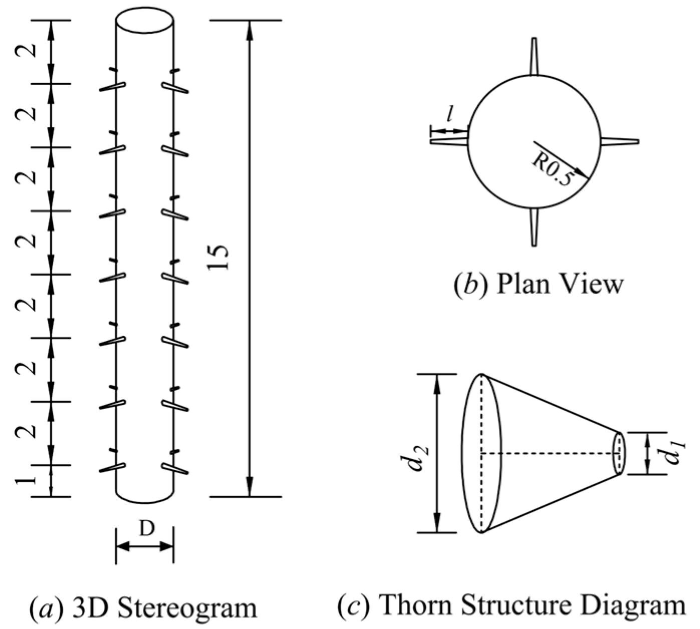
To elucidate the mechanism of pile–soil interaction and consider the boundary effect, the soil model is set as a homogeneous cylinder measuring a diameter of 20 m and a height of 20 m, with a bearing layer thickness of 5 m. In the pile model, the pile diameter (D) is 1 m, the pile length (L) is 15 m, the shape of the pile thorn is set as a cylinder and circular truncated cone, the thorn length is 0.5 m (0.5 D), and the pile body comprises seven layers of pile thorns. The layer spacing of the thorns is 2 m, and the bottom layer is 1 m away from the pile end. Figure 2 depicts the calculation model. Considering the convenience of the construction, a section is set up with four symmetrically arranged thorns. To investigate the influence of the thorn shape on the compressive bearing capacity of the pile, based on the principle of equal-volume special-shaped peripheral expansion, five types of circular truncated cones with different tapers are set, respectively, and compared with the smooth pile. Figure 3 presents the structure schematic diagram of the thorn pile, and the dimensions of the pile thorn are illustrated in Table 1.
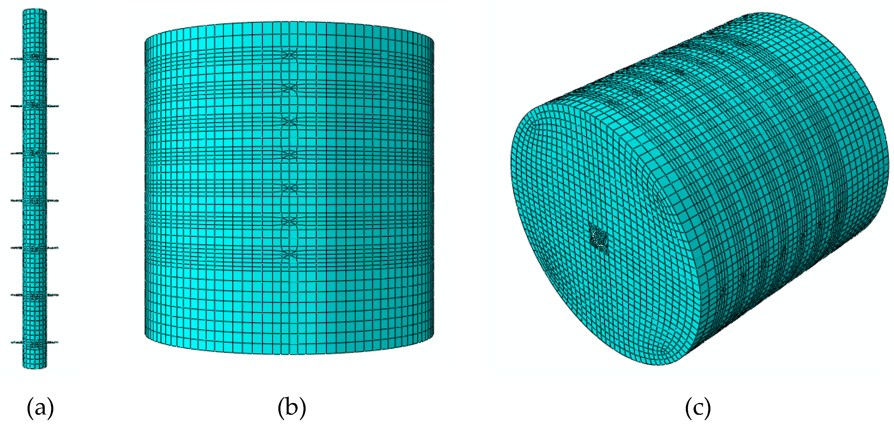
Due to the complexity of the pile thorn geometry, techniques such as cutting sections, structured meshing, and local refinement were used to divide the pile–soil model. The global mesh sizes of soil and pile are 0.63 and 0.2, respectively. Local densification was applied to the soil around the piles and pile thorns with five grid points distributed along the contact edge to ensure calculation accuracy. C3D8R eight-node linear hexahedral elements were used for both soil and foundation piles. A fixed displacement constraint is applied to the bottom of the model, a ZASYMM antisymmetric constraint is applied to the side, and the ground surface is set as a free surface. Figure 4 depicts the grid cell model of the 3# pile.

2.2. Material Parameters

It is assumed that the pile body is C30 concrete, and a linear elastic model is adopted. Since the root of the pile thorn is a stress concentration zone, Q355 steel is used for the thorn with a bilinear kinematic hardening model. According to the actual measurement results [56], the yield strength is 380.2 MPa, the ultimate strength is 538.5 MPa, and the ultimate strain is 15%. The soil is considered an elastoplastic material using the Mohr–Coulomb yield criterion. Referring to the actual engineering geological conditions [57], the material mechanical parameters of pile–soil are proposed and described in Table 2.
The pile–soil interaction was simulated using the master-slave contact algorithm in ABAQUS. The pile and soil were set as the primary control and subordinate surface, respectively. The normal interaction was set as “hard contact”, and the tangential interaction was defined as the friction model. Due to the lack of measured data, as stated in the application of ABAQUS in geotechnical engineering [58], the friction coefficient of the pile–soil interface is proposed to be 0.34 (tan (0.75φ)).

2.3. Numerical Analysis

Before the numerical analysis, it is necessary to design a reasonable analysis step, such as setting the boundary conditions of the model, balancing the initial geostress, adding contact pairs, and applying loads [59]. The analysis process of this model is as follows:
(1) Initial analysis step: Define the boundary conditions for the initial state of the model.
(2) Initial ground stress equilibrium: Using model change technology, temporarily remove the pile so that the model consists solely of the soil layer, applying only gravitational force to the soil to balance the initial stress. The stress and displacement nephograms of the smooth pile and 3# pile after ground stress equilibrium are shown in Figure 5.
(3) Activate the pile, apply gravitational force to the pile, and simultaneously add contact between the pile and soil.
(4) Apply a vertical displacement load of 0.07 m to the pile top.

2.4. Model Verification

According to the technical code of building pile foundations, the empirical parameter method is used to estimate the ultimate bearing capacity of a single pile. The specific formula is as follows:
Q u k = Q s k + Q p k = u Σ q s i k l i + q p k A p
where Qsk and Qpk are the standard values of total ultimate shaft resistance and total ultimate tip resistance, respectively; u is the circumference of the pile body; li is the thickness of layer i soil; Ap is the area of the pile end; and qsik is the standard value of ultimate shaft resistance of layer i soil on the pile side. Since this model does not consider the soil-squeezing effect of pile foundation, the value range can be taken as 24~42 kPa according to Table 5.3.5-1 in the standard [60]. qpk is the standard value of ultimate tip resistance. Since the pile-end soil is medium-dense silt, the value range can be taken as 500~650 kPa according to Table 5.3.5-2. Thus, Quk is determined to be 1522.9 to 2488.45 kN.
Through the numerical simulation of the load test of a smooth pile using ABAQUS, the ultimate vertical bearing value of a single pile is 1651.7 kN, which falls within the range of empirical solutions, thereby validating the reliability of the numerical simulation method in this paper. Although factors such as mesh size, contact behavior, and material constitutive models may affect the accuracy of the results, the thorn piles were set up using the exact same method as the smooth piles, ensuring the validity of the comparative study.

3. Analysis of Results

3.1. Load-Settlement Analysis

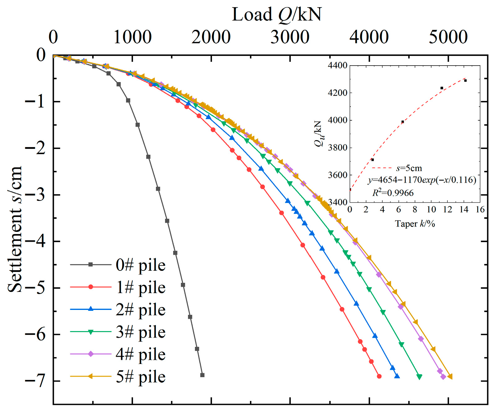
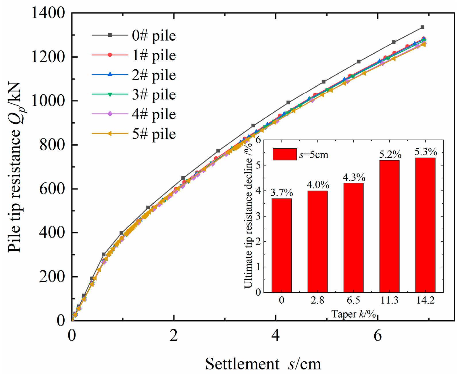
Figure 6 depicts the pile top load settlement curves of smooth piles and different thorn piles, and the Q-s curves show a slow variation with obvious rules. Analysis reveals that:
(1) Under the same load, the bearing capacity of the thorn pile is better than that of the smooth pile, and the settlement of the pile top decreases with the increase in the thorn taper. According to the technical code for testing building foundation piles [61], for the Q-s curve of slow variation, when the pile diameter is greater than 800 mm, the load value corresponding to settlement s = 0.05 D can be used as the ultimate compressive capacity of a single pile. When s = 5 cm, the ultimate compressive bearing capacity of a single pile increases exponentially with the increase in thorn taper, and the ultimate bearing capacity of a 5# pile is 1.6 times greater than that of the smooth pile. Therefore, considering the mechanical performance and construction convenience, the pile with conical thorns is recommended in practical engineering design.
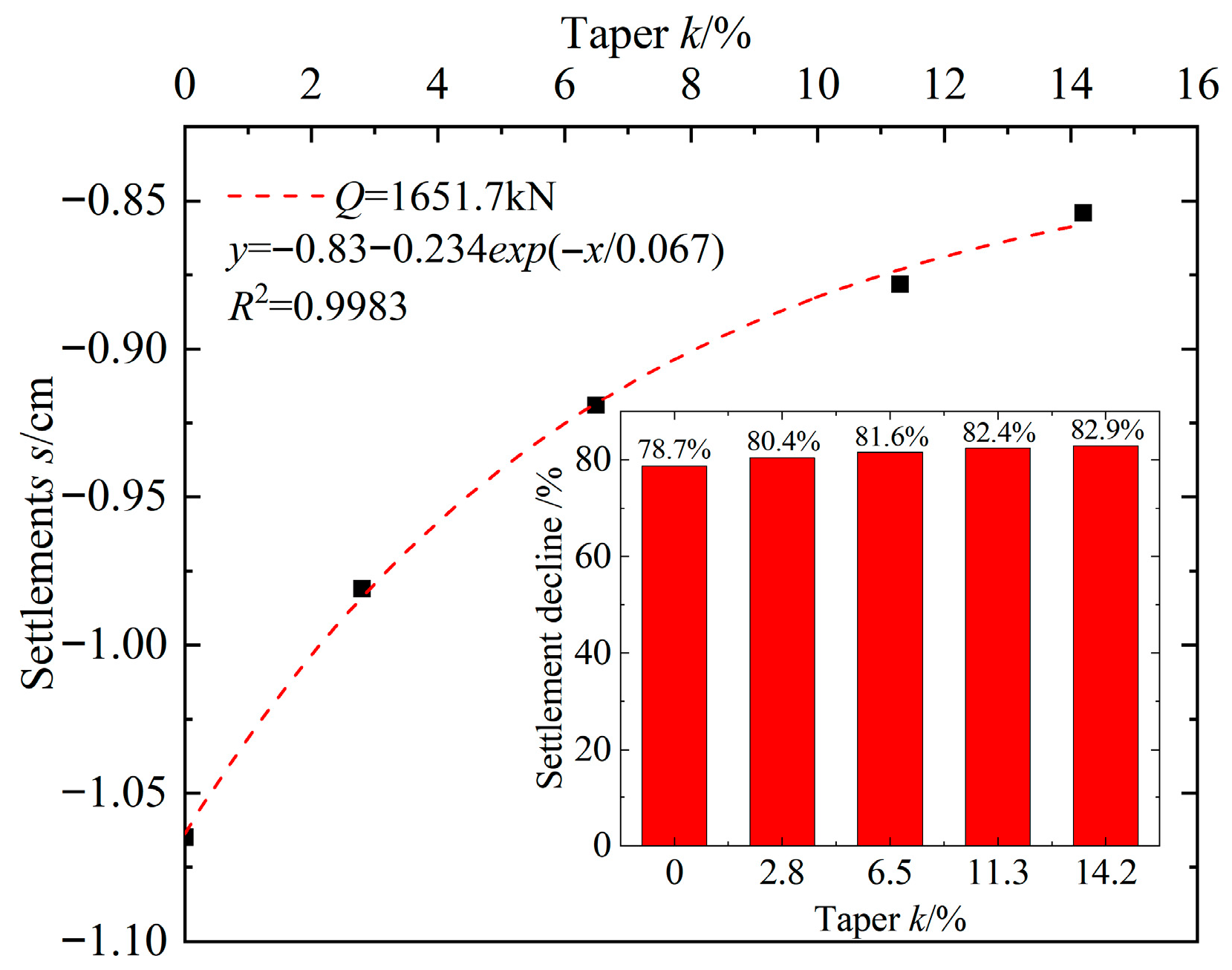
(2) When the ultimate bearing capacity of smooth pile Qu = 1651.7 kN is selected, the relationship curve between pile top settlement and pile thorn taper is obtained, as shown in Figure 7. With the increase in taper, the displacement of the pile top decreases exponentially, and the settlement of the 5# pile is the smallest, which is 82.9% lower than that of the smooth pile, indicating that the increase in thorn structure can effectively reduce the settlement of the pile foundation.
(3) The influence of thorn shape on the bearing capacity of the pile and pile top settlement is not significant. When the thorn taper is greater than 0.113, the increase in ultimate bearing capacity and the decrease in pile top settlement tend to be gentle.

3.2. Influence of Thorn Shape on Pile Tip Resistance

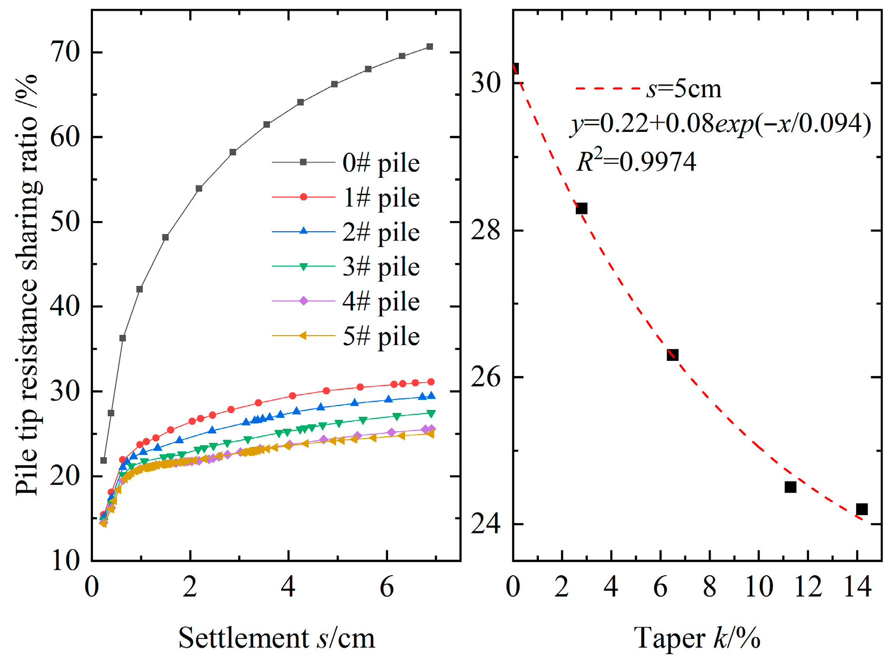
Figure 8 and Figure 9 depict the influence of different thorn shapes on pile tip resistance. The analysis is as follows:
(1) Under the same pile top displacement, the pile tip resistance of the thorn pile is significantly lower than that of the smooth pile. The pile tip resistance decreases with the increase in the thorn taper, and the ultimate tip resistance of a 5# pile is 5.3% lower than that of a smooth pile. In the limit state (s = 5 cm), the pile top load of a 5# pile is much larger than that of a smooth pile, which makes the elastic compression of its pile body larger and the actual penetration settlement at the pile tip relatively small. As a result, the tip resistance is slightly underutilized, resulting in a minor difference in the tip resistance.
(2) The influence of different thorn shapes on the pile tip resistance sharing ratio is the same, and the pile tip resistance sharing ratio increases with the increase in pile top settlement. Under the same displacement of the pile top, the resistance sharing ratio of the pile tip is smaller than that of the smooth pile. It decreases with the increase in the thorn taper, indicating that the role of the pile tip is gradually weakening.
(3) In the limit state, the resistance sharing ratio of the pile tip decreases exponentially with the increase in the taper. Compared with a smooth pile, a 5# pile tip resistance sharing ratio decreases by 42.2%. This indicates that the thorn structure alters the load transfer mechanism of the thorn pile, dispersing stress into the shallow soil through the thorns, significantly reducing the pressure requirements on the soil at the pile tip, and enhancing adaptability to the foundation soil.

3.3. Influence of Thorn Shape on Pile Shaft Resistance

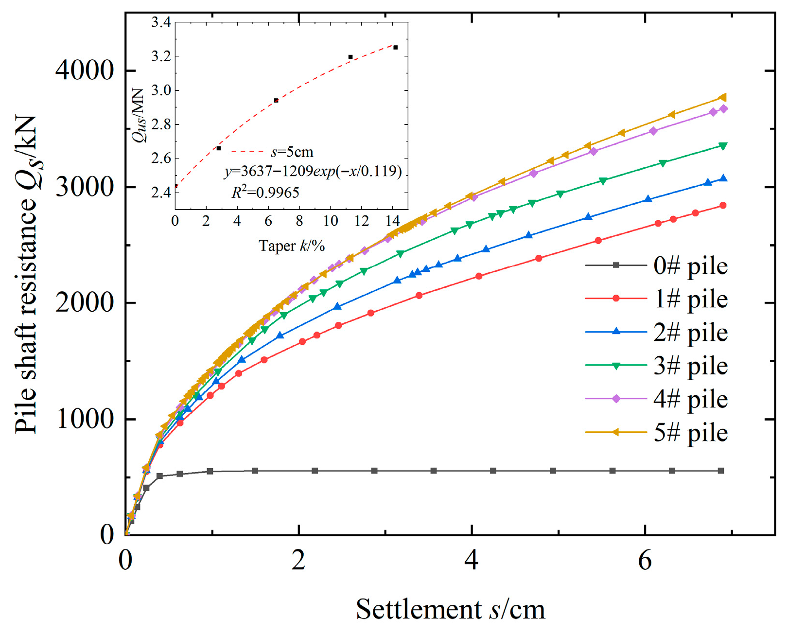
Since the thorns are located on the lateral surface of the pile body, the impact of the thorn structure is summarized as the pile shaft resistance. Figure 10 and Figure 11 show the influence of different thorn shapes on pile shaft resistance. The analysis shows that:
(1) The shaft resistance of a smooth pile tends to be gentle after 0.5 cm of pile top settlement, and the shaft resistance softening phenomenon appears. However, the shaft resistance of the thorn pile and the pile top settlement show a hardening law, and the hardening trend becomes more significant with the increase in the thorn taper, indicating that the softening mechanical characteristics of the pile shaft resistance can be effectively changed by adding the thorn structure of the lateral surface of the pile.
(2) The impact of pile thorns on pile shaft resistance is significant. The ultimate shaft resistance of a single pile increases exponentially with the increase in the thorn taper, and the ultimate shaft resistance of a 5# pile is 4.85 times higher than that of a smooth pile. In practical engineering, for bad geological conditions such as deep soft or karst foundations, it is not necessary to blindly increase the pile length to drive the pile end into the bearing layer but to increase the shaft resistance of the pile by increasing the pile thorns and make full use of the mid-bearing effect of the pile to improve the overall bearing capacity of the pile.
(3) The share ratio of pile shaft resistance decreases with the increase in pile top settlement, indicating that the pile tip resistance is continuously playing a role. In the limit state, it increases exponentially with the increase in the thorn taper, and the pile shaft resistance sharing ratio of a smooth pile and a 5# pile is 33.6% and 75.8%, respectively. The increase in thorn structure changes the bearing property of the pile foundation and gradually transforms it from an end-bearing pile to a mid-bearing pile.

3.4. Influence of Thorn Shape on Pile Axial Force

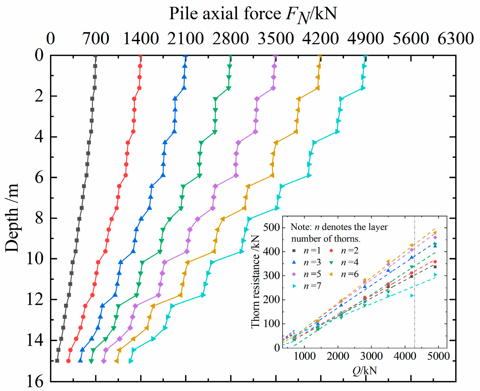
Figure 12 illustrates the axial force distribution diagram of the pile body with different thorn shapes when the load Q = 1700 kN. Figure 13 shows the axial force distribution diagram of a 5# pile under the 7-level load (700–4900 kN). The analysis is as follows:
(1) As illustrated in Figure 12, the influence of thorn shape on the pile axial force is not significant, but the axial force distribution of the thorn pile differs from that of the smooth pile. Due to the mid-bearing effect of the pile thorns, the axial force changes sharply at the upper and lower ends of the thorns, and the axial force decreases significantly. The axial force loss is fully borne by the pile thorns and transferred to the soil around the pile so that the pile tip resistance decreases significantly. This is the outstanding feature of the load transfer and the reason for the high bearing capacity of the thorn pile.
(2) Figure 13 shows that at the initial loading stage, the pile top load of the 5# pile is mainly borne by pile side friction resistance. With the increase in pile top load, the pile axial force is gradually transmitted downward, among which the pile thorn bears most of the load. At the limit state, the sharing ratio of pile thorn resistance and pile side friction resistance is 56.3% and 19.4%, respectively. Therefore, the thorn pile can be characterized as a friction mid-bearing pile.
(3) Under the action of the load, the play of pile thorns in each layer is not synchronous, which has an obvious space–time effect. In the limit state, the resistance of each layer of thorn is ranked 6-5-3-4-2-1-7, from largest to smallest. Evidently, the middle and lower thorns are the main load-bearing components, and the bearing capacity of the sixth layer thorns is maximized, while that of the seventh layer is minimized. Due to the high overburden pressure, high confining pressure, and thick bearing layer, the middle and lower thorns become the most efficient load-bearing areas. However, the thorn at the seventh layer is 1 m from the pile tip and is located in the strong interference zone at the pile tip. Affected by factors such as weak lateral confinement and a thin bearing layer, its bearing capacity is severely constrained. Therefore, in actual engineering design, the focus should be on optimizing the middle and lower thorns. It is recommended that the lowermost thorns be left with sufficient distance to avoid the strong interference zone at the pile tip.

4. Discussion

4.1. Pile and Soil Interaction Mechanism

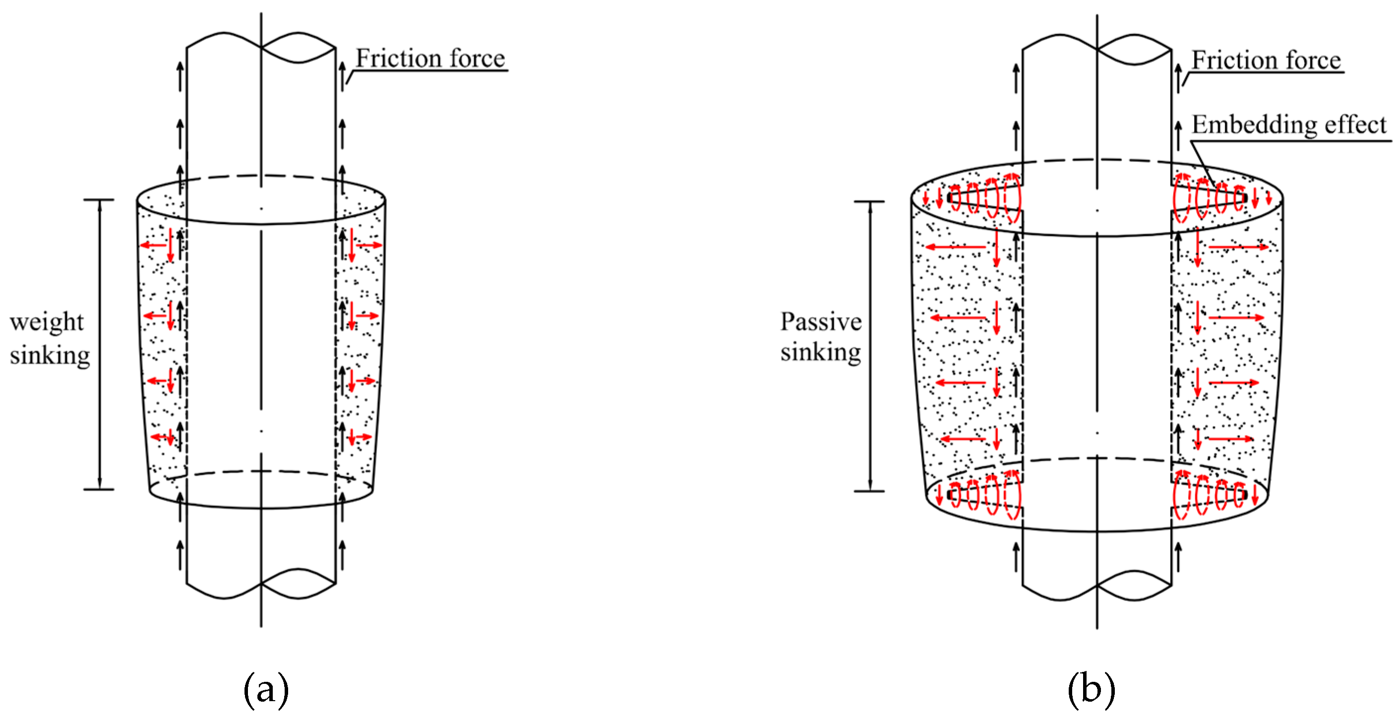
According to the force analysis, compared with the smooth pile, the pile shaft resistance of the thorn pile increases the complex embedding effect at the thorn–soil interface, primarily manifested by the end bearing force of the thorn and the friction force at the thorn–soil interface. During the initial loading stage of the smooth pile, the interface between the pile and soil is subjected to static frictional force, causing the surrounding soil to settle synchronously with the pile body. With the increase in load, the soil particles near the pile top first appear to be damaged. At this time, the pile–soil interface will be affected by sliding friction, and the pile and soil will produce relative displacement. Subsequently, the upper soil particles will sink with the downward movement of the lower soil. Figure 14a depicts the stress analysis. For the thorn pile, the effect of adding the thorn structure on the side surface of the pile is similar to the soil reinforcement by roots. When the pile top load is small, the pile and soil sink synchronously. With the increase in load, the pile body will move down and compress. The soil between the thorns will be passively compressed due to the limiting effect of the thorns, which increases the effective stress of the soil, thereby improving the critical friction of the pile–soil interface. Furthermore, the friction increases with the increase in the pile body displacement, which then improves the shear strength of the pile–soil interface. Conversely, in the loading process, the soil below the thorn will have upward flow due to the downward movement of the pile body, as illustrated in Figure 14b, while the soil above the thorn is compressed laterally. These two effects promote the rearrangement of the soil particles, increase the compactness of the soil around the thorn, and improve the restraining reaction force of the soil on the thorn structure to provide higher pile thorn resistance under the load.
Under the load, the soil particles around the pile will move downward together with the pile, showing two forms: vertical movement and rotation. When the load is small, the soil particles adjacent to the pile sink synchronously with the pile, resulting in a collective downward movement of the soil particles. As the pile displacement increases, the soil particles adjacent to the pile must move away from the pile after squeezing and tumbling, thus driving the soil particles within a certain thickness range around the pile to move downward. The embedding effect of the thorn–soil interaction results in greater thickness than that of the smooth pile under the same conditions, thereby extending the influence range of the surrounding soil and optimizing the load transfer pathway, which markedly enhances the bearing capacity and stability of the thorn pile. Figure 15 illustrates that at the limit state, a “disc-shaped” displacement mutation zone is formed around the thorn, and the influence range of the soil around the pile increases as the thorn taper increases.
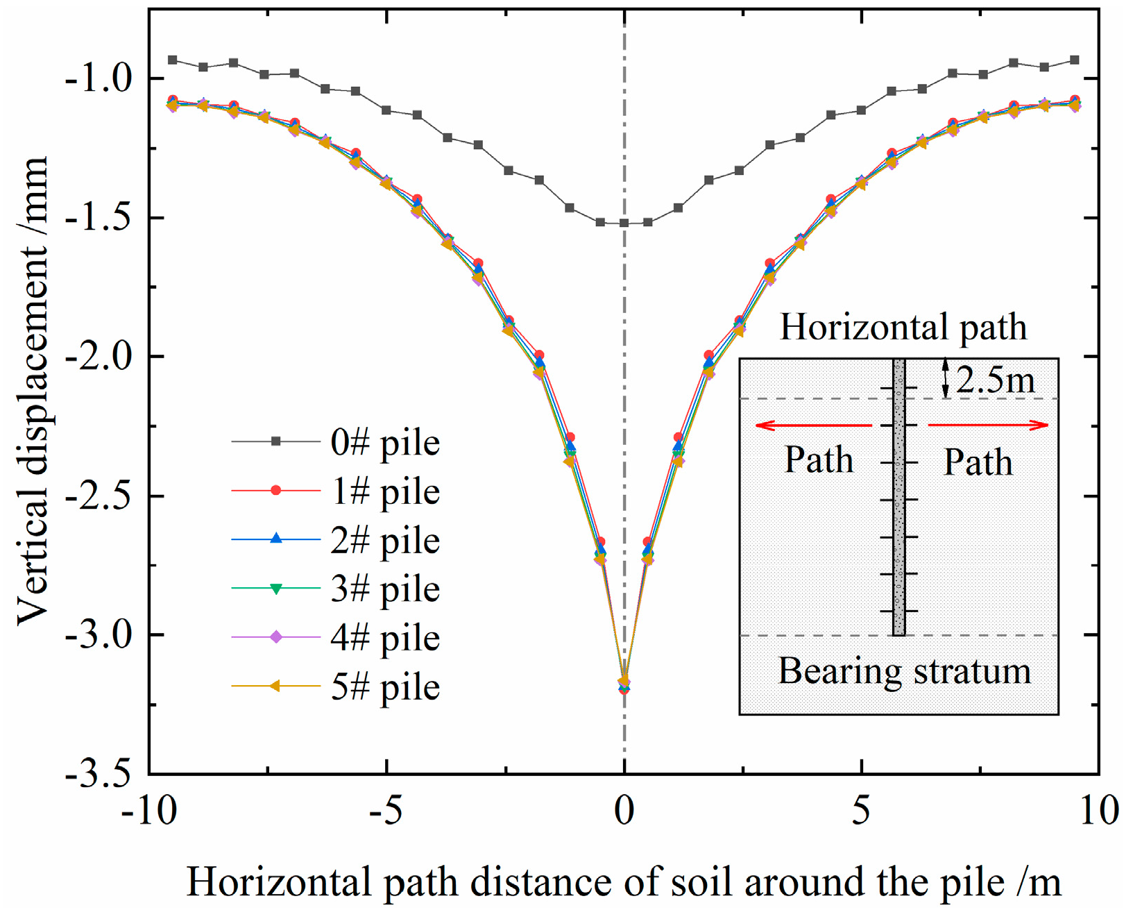
Taking the pile top load Q = 1700 kN as an example, the soil particles at the position 2.5 m away from the pile top are selected to explore further the variation law of the vertical deformation of the soil around the pile along the horizontal path and the relative displacement of the pile and soil, as illustrated in Figure 16 and Figure 17.
(1) The soil settlement around the pile decreases along the radial direction, showing an inverted triangle distribution. The settlement of the soil around the thorn pile is significantly greater than that around the smooth pile, which verifies that the existence of the thorn structure can effectively expand the influence range of soil around the pile.
(2) As the thorn taper increased, the relative displacement of pile and soil decreased exponentially, although the reduction was minimal. When Q = 1700 kN, the relative displacement between the smooth pile and soil measures about 52 mm, whereas the 5# pile exhibits only 5.6 mm of displacement. This further substantiates that the thorn structure facilitates the simultaneous downward displacement of the surrounding soil, thereby effectively transferring the upper load to the soil around the pile. At this time, the soil is similar to the enlarged body of the pile, and its capacity is fully utilized so that the shaft resistance of the pile is effectively improved.
(3) In practical engineering involving soft soil foundation, post-grouting technology at the pile side can enhance the shear strength of the surrounding soil. The embedded effect of the thorn soil redistributes and bears the upper structural loads, thereby diminishing the settlement displacement of the pile foundation and enhancing the bearing capacity of the thorn pile, effectively addressing the bearing issues associated with poor foundation.

4.2. Analysis of Influencing Factors

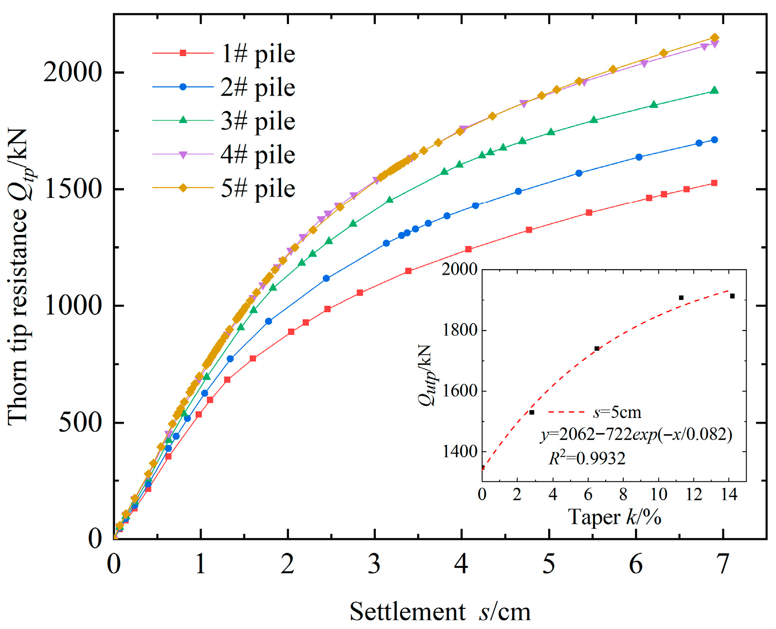
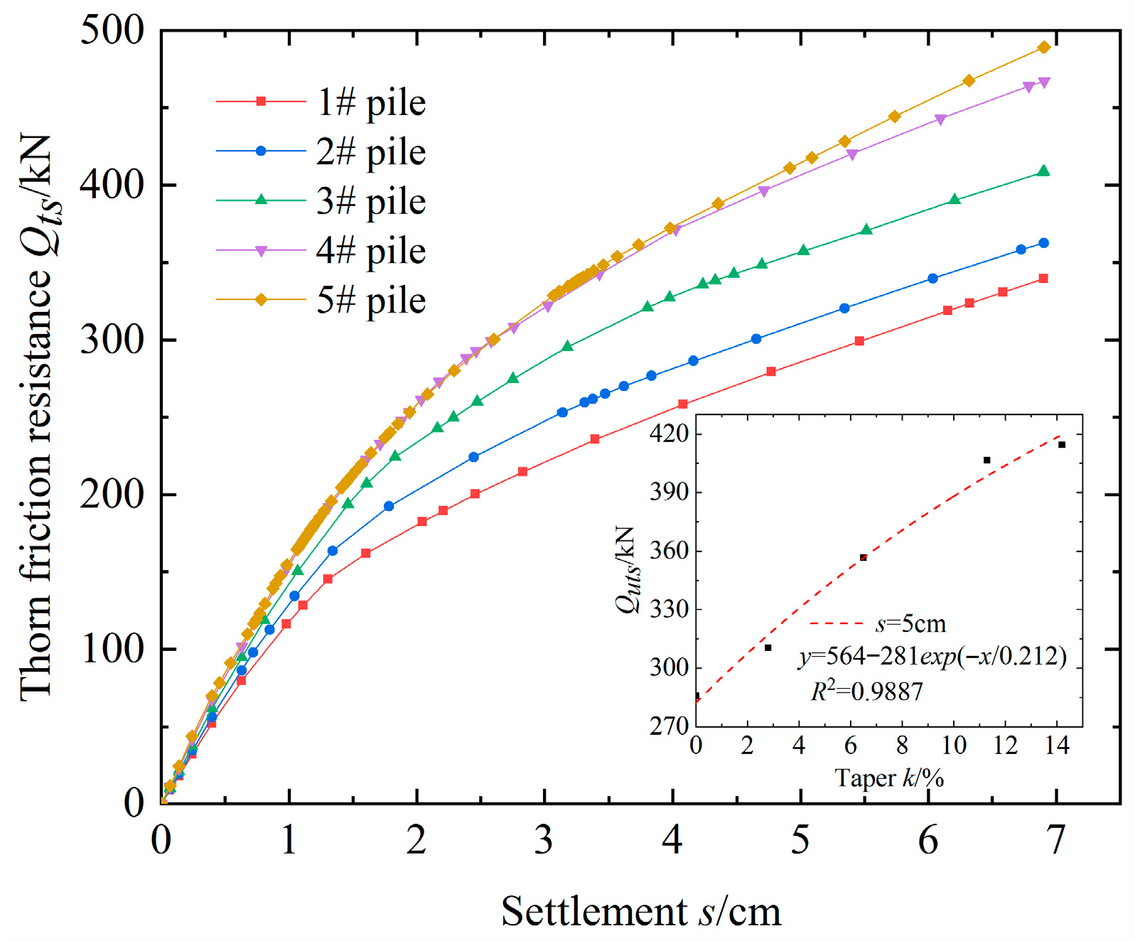
To further analyze the influence of the thorn shape on the bearing mechanism of thorn piles, the following sections present the influence law of the thorn taper on the thorn tip resistance Qtp, thorn friction resistance Qts, and pile body friction resistance Qbs. The analysis reveals the following:
(1) Under the same conditions of pile top settlement, both the thorn tip resistance and the thorn friction resistance increase with the increase in thorn taper, and their respective ultimate values increase exponentially with the thorn taper, as illustrated in Figure 18 and Figure 19. Compared to the 1# pile, the 5# pile increases by 41.9% and 45% for Qutp and Quts, respectively, further confirming that the optimal shape for the pile thorn is a cone. The high tapered thorn has the unique advantage of a divergent conical surface. When loaded, they can convert the vertical load into tangential and normal components, exerting powerful radial thrust on the surrounding soil. This causes lateral compression of the soil around the thorn structure, significantly increasing soil density and effective stress. Additionally, this thrust can more effectively stimulate the deeper soil, transmitting the load to a wider range.
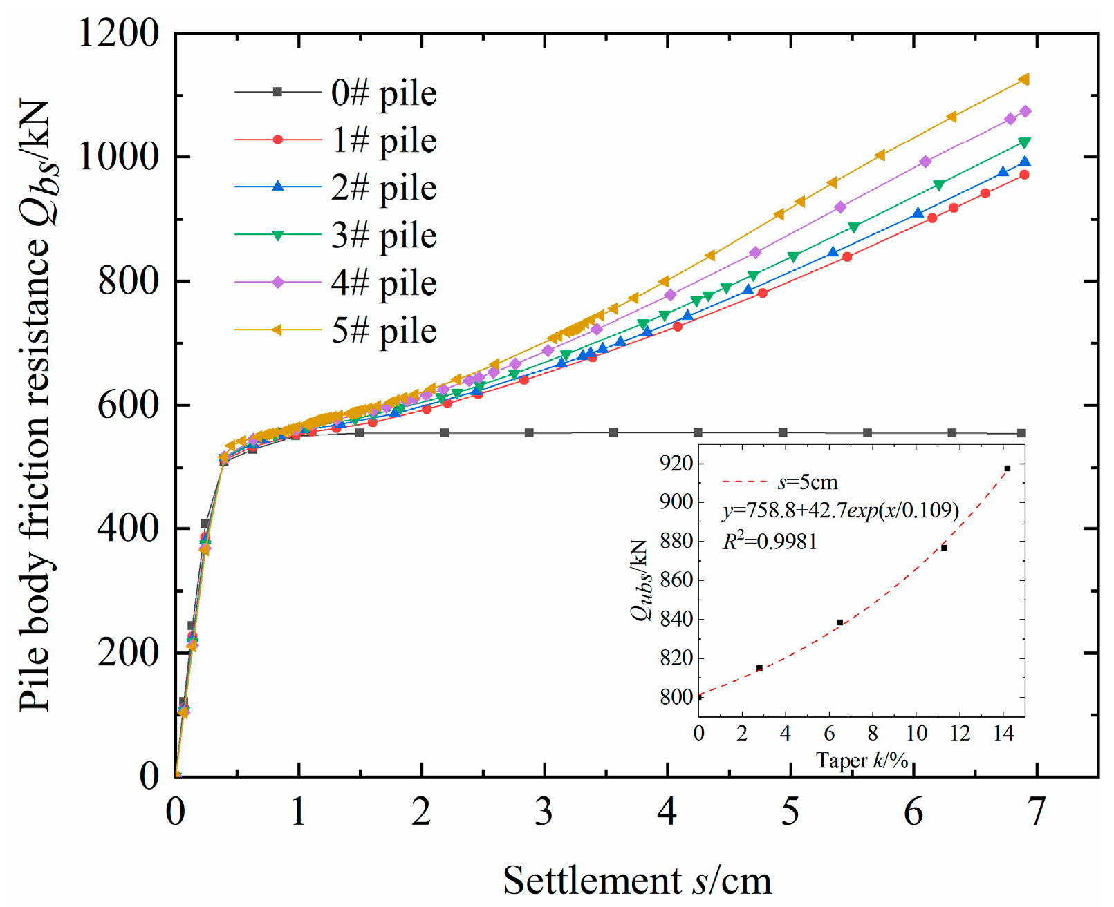
(2) Compared to the smooth pile, the pile body friction resistance and pile top settlement exhibit a linear hardening pattern, as illustrated in Figure 20. In the limit state, the pile body friction resistance increases exponentially with the thorn taper. The 5# pile increased by 14.7% and 65.1% for Qubs compared to the 1# pile and the smooth piles, respectively. The results indicate that the significant increase in the pile body friction resistance verifies the phenomenon of increased effective stress of the soil around the pile during loading.
(3) According to the force analysis, the shaft resistance Qs of the thorn pile can be expressed as follows:
Q s = Q t p + Q t s + Q b s
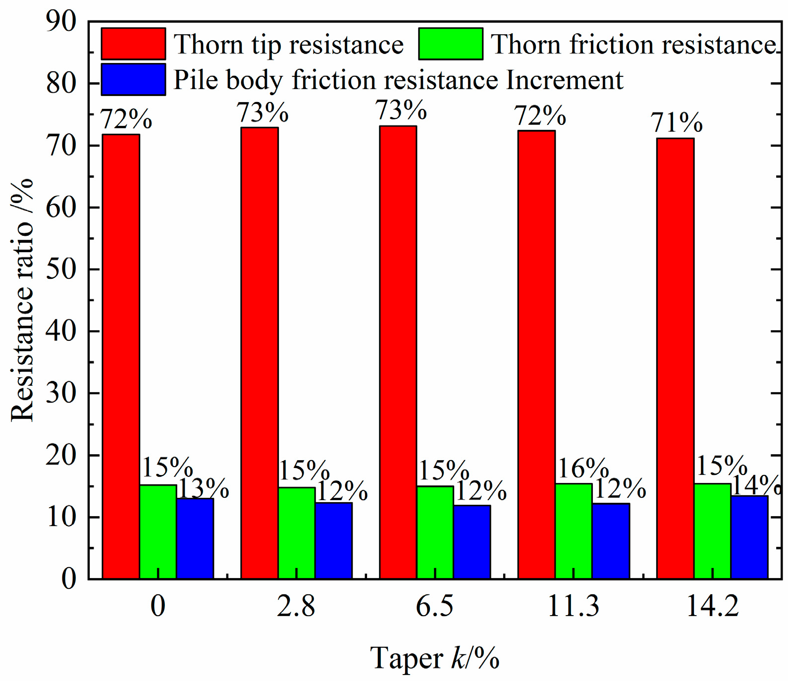
Figure 21 shows the contribution patterns of the three-phase resistances Qtp, Qts, and Qbs of different tapered thorn piles to the increase in shaft resistance. The results indicate that the contribution patterns of the three-phase resistances are generally consistent. Among the additional bearing capacity, the thorn tip resistance accounts for the largest proportion, while the increase in the pile body friction resistance accounts for the smallest proportion, with average proportions of 72%, 15%, and 13%, respectively. This indicates that a thorn pile is a foundation form that primarily relies on end-bearing effects and secondarily on friction effects. Its core value lies in effectively transferring loads to deeper and wider soil layers through the thorn structure, while simultaneously improving the compaction of the soil around the pile. Therefore, the focus in engineering design should be on optimizing the thorn tip resistance, with thorn design emphasizing the expansion of the end area and gradual variable cross-section, such as a truncated conical thorn.

5. Conclusions

In this paper, five pile–soil interaction models with different thorn shapes are established to study the bearing capacity and action mechanism of thorn piles under a homogeneous silt foundation. The main conclusions are as follows:
(1) Compared with the smooth pile, the thorn pile exhibits significant advantages in compressive bearing capacity and deformation resistance. Furthermore, the ultimate bearing capacity of the 5# pile is 1.6 times higher than that of the smooth pile, while the pile top settlement is reduced by 82.9%.
(2) The addition of a thorn structure on the pile side surface can effectively change the mechanical characteristics of pile shaft resistance softening and significantly enhance the pile shaft resistance. The shaft resistance of the 5# pile is 4.85 times higher than that of the smooth pile.
(3) The outstanding characteristic of the thorn pile load transfer is the significant reduction in the axial force at both the upper and lower ends of the thorn. In the limit state, the load at the pile top is borne by pile tip resistance, pile side friction resistance, and pile thorn resistance, with the pile thorn resistance accounting for the largest proportion, exceeding 50%, thereby characterizing it as a friction mid-bearing pile.
(4) Due to the unique characteristic of the divergent conical surface, the truncated conical thorns exert a powerful radial pressure on the surrounding soil under load, increasing the effective stress of the soil around the pile, expanding the influence range of the soil around the pile, and fully mobilizing the shear resistance of the soil, thereby enhancing the bearing capacity of the thorn pile through an increase in pile shaft resistance.
(5) The high tapered thorn can significantly enhance the pile shaft resistance. Consequently, it is recommended to give priority to the utilization of the conical thorn in engineering design. Focus on optimizing the middle and lower thorns, and ensure that the lowermost thorns are kept at a sufficient distance from the pile tip to avoid strong interference zones, thereby optimizing bearing performance.
Further research is required on the microscopic motion law of soil particles around the pile and the interaction mechanism between the thorn and the soil. There is a lack of research on the seismic performance of thorn piles in poor foundations [62,63,64].

Author Contributions

Conceptualization, P.D. and X.L.; methodology, X.L. and C.F.; software, P.D.; validation, P.D.; formal analysis, P.D. and X.L.; investigation, X.L.; resources, D.Z.; data curation, P.D.; writing—original draft preparation, P.D.; writing—review and editing, X.L.; visualization, P.D.; supervision, D.Z.; project administration, C.F.; funding acquisition, P.D. and X.L. All authors have read and agreed to the published version of the manuscript.

Funding

This work was financially supported by the Natural Science Youth Foundation of Hainan Province (521QN266), the Education Department of Hainan Province (Hnjg2025-144 and Hnky2022-47), and the Haikou College of Economics Teaching Reform Project (Hjyj2024093), which are all greatly appreciated.

Data Availability Statement

Data will be made available on request.

Conflicts of Interest

The authors declare no competing interests.

References

  1. Fu, Y.; Zhang, Y.; Li, G.; Xie, S.; Shi, J. Experimental study on characteristics of tooth pile under vertical load. Yangtze River 2020, 51, 184–190. [Google Scholar]
  2. Fu, Y.; Du, P.; Zhang, Y.; Li, G.; Cao, Z.; Liu, X. Model Test on Pullout Resistance Characteristics of Multi-tooth Pile in Sand. J. Yangtze Riv. Sci. Res. Inst. 2021, 38, 121–126. [Google Scholar]
  3. Du, P.; Fu, Y.; Liu, X.; Li, G. Model Test Study on the Load-bearing Behaviour of Multi-tooth Piles under Different Bearing Layers. KSCE J. Civ. Eng. 2023, 27, 955–965. [Google Scholar] [CrossRef]
  4. Xiong, H.; Niu, Z.; Jang, Y.; Yang, J.; Zhou, Z. Experimental study of bearing characteristics of new ribbed prestressed pipe piles. China Concr. Cem. Prod. 2009, 32–35. [Google Scholar] [CrossRef]
  5. Fang, P.; Qi, J.; Zhou, Z. Comparative study on bearing capacity of enhanced pretensioned spun concrete piles and conventional pipe piles. Chin. J. Geotech. Eng. 2013, 35 (Suppl. S2), 1020–1023. [Google Scholar]
  6. Guo, Z.; Wei, L.; Feng, S.; He, Q. Load-settlement behavior and simulation analysis of enhanced prestressed pipe piles. Build. Struct. 2014, 44, 77–81. [Google Scholar]
  7. Wang, Z.; Fang, P.; Xie, X.; Wang, K.; Wang, W.; Li, J. Analysis of effected factors for vertical compressive bearing capacity of ribbed bamboo joint pile. Rock. Soil. Mech. 2018, 39, 381–388. [Google Scholar] [CrossRef]
  8. Gao, X.; Wang, J.; Zhu, X. Static load test and load transfer mechanism study of squeezed branch and plate pile in collapsible loess foundation. J. Zhejiang Univ. Sci. A 2007, 8, 1110–1117. [Google Scholar] [CrossRef]
  9. Zhang, M.; Xu, P.; Cui, W.; Gao, Y. Bearing behavior and failure mechanism of squeezed branch piles. J. Rock. Mech. Geotech. Eng. 2018, 10, 935–946. [Google Scholar] [CrossRef]
  10. Ma, H.; Wu, Y.; Tong, Y.; Jiang, X. Research on bearing theory of squeezed branch pile. Adv. Civ. Eng. 2020, 2020, 6637261. [Google Scholar] [CrossRef]
  11. Shi, D.; Xiao, J.; Yang, C.; Liu, B. Research on the Plate Cavity Geometry of the Squeezed Branch Pile. Procedia Eng. 2014, 73, 29–34. [Google Scholar] [CrossRef][Green Version]
  12. Chen, Y.; Deng, A.; Lu, F.; Sun, H. Failure mechanism and bearing capacity of vertically loaded pile with partially-screwed shaft: Experiment and simulations. Comput. Geotech. 2020, 118, 103337. [Google Scholar] [CrossRef]
  13. Shao, K.; Su, Q.; Liu, J.; Liu, K.; Xiong, Z.; Wang, T. Optimization of inter-helix spacing for helical piles in sand. J. Rock. Mech. Geotech. Eng. 2022, 14, 936–952. [Google Scholar] [CrossRef]
  14. Ma, J.; Wang, R.; Hu, Z.; Mu, T.; Liu, A.; Olusegun, V.T. Limit equilibrium theory in calculating screw pile bearing capacity under compression. Proc. Inst. Civ. Eng.-Geotech. Eng. 2023, 177, 468–481. [Google Scholar] [CrossRef]
  15. Meng, Z.; Chen, J.; Wang, J. Numerical analysis of bearing capacity of drilled displacement piles with a screw-shaped shaft in sand. Mar. Georesources Geotechnol. 2017, 35, 661–669. [Google Scholar] [CrossRef]
  16. Ma, H.; Liu, L.; Wang, P.; Yuan, S.; He, Q.; Yang, X. Calculation method and mechanism of ultimate side resistance of screw pile. Mar. Georesources Geotechnol. 2023, 41, 99–113. [Google Scholar] [CrossRef]
  17. Dou, D.; Gao, Q. Research on Influential Factors and Vertical Bearing Capacity of Screw Piles. Port. Eng. Technol. 2020, 57, 55–58. [Google Scholar]
  18. Ma, J.; Luo, L.; Mu, T.; Guo, H.; Tang, Y. Experimental study on characteristics of pile-soil interaction in screw piles. Buildings 2022, 12, 2091. [Google Scholar] [CrossRef]
  19. Yang, T.; Zheng, W.; Xie, Y.; Zhang, H.; Yue, X. Evaluating screw-shaft pile composite foundations in round Gravelly soil: A study using model tests and numerical simulations. Heliyon 2023, 9, e20887. [Google Scholar] [CrossRef] [PubMed]
  20. Khidri, M.; Deng, L. Field axial cyclic loading tests of screw micropiles in cohesionless soil. Soil Dyn. Earthq. Eng. 2021, 143, 106601. [Google Scholar] [CrossRef]
  21. Khidri, M.; Deng, L. Field axial loading tests of screw micropiles in sand. Can. Geotech. J. 2022, 59, 458–472. [Google Scholar] [CrossRef]
  22. Sanzeni, A.; Danesi, E.G. Field tests and interpretation of screw micropiles subjected to axial loading in cohesive soil. Int. J. Geotech. Eng. 2022, 16, 391–399. [Google Scholar] [CrossRef]
  23. Fang, C.; Zhang, X.; Peng, G. Discussion on the Bearing Force Characteristic and the Failure Behavior of a New Kind Half-screwed Filling Pile. Geotech. Eng. Techn. 2006, 20, 316–319. [Google Scholar]
  24. Wang, S.; Feng, Z.; Tang, J.; Zhao, Z. Experimental study on bearing mechanism of screw cast-in-place piles under vertical loads. Chin. J. Geotech. Eng. 2021, 43, 383–389. [Google Scholar]
  25. Chen, Y.; Yu, Y.; Dong, Y.; Sun, H.; Gong, C. Experimental Study on Working Behavior of Vertically Loaded Screw-shaft Pile. Chin. J. Undergr. Sp. Eng. 2022, 18, 860–867. [Google Scholar]
  26. Wei, J.; El Naggar, M.H. Experimental study of axial behaviour of tapered piles. Can. Geotech. J. 1998, 35, 641–654. [Google Scholar] [CrossRef]
  27. El Naggar, M.H.; Wei, J. Axial capacity of tapered piles established from model tests. Can. Geotech. J. 1999, 36, 1185–1194. [Google Scholar] [CrossRef]
  28. He, J. Behavior Characteristics Research on TaperedPile in Soft Clay Foundation. Master’s Thesis, Hunan University of Technology, Hunan, China, 2008. [Google Scholar]
  29. Liu, J.; He, J.; Min, C. Contrast research of bearing characteristic for composite foundation with tapered piles and cylindrical piles. In Proceedings of the 18th East Asia-Pacific Conference on Structural Engineering and Construction, Guangzhou, China, 28 November 2009; School of Civil Engineering and Architecture, Hunan University of Technology: Zhuzhou, China, 2009; pp. 301–307. [Google Scholar]
  30. Wang, N.; Le, Y.; Hu, W.; Fang, T.; Zhu, B.; Geng, D.; Xu, C. New interaction model for the annular zone of stepped piles with respect to their vertical dynamic characteristics. Comput. Geotech. 2020, 117, 103256. [Google Scholar] [CrossRef]
  31. Jiang, S.; Huang, M.; Fang, T.; Chen, W.; Xing, S. A new large step-tapered hollow pile and its bearing capacity. Proc. Inst. Civ. Eng.-Geotech. Eng. 2020, 173, 191–206. [Google Scholar] [CrossRef]
  32. Zhang, X.; Wang, J.; Yang, Z.; Gong, X.; Xu, R. Analytical solutions for laterally loaded step-tapered piles by state space method. Chin. J. Geotech. Eng. 2023, 45, 1944–1952. [Google Scholar]
  33. Fang, T. Study on Deformation and Load-Bearing Characteristics of Segmentally Variable Cross-Section Pile. Ph.D. Thesis, Chongqing University, Chongqing, China, 2012. [Google Scholar]
  34. Dickin, E.A.; Leung, C.F. The influence of foundation geometry on the uplift behaviour of piles with enlarged bases. Can. Geotech. J. 1992, 29, 498–505. [Google Scholar] [CrossRef]
  35. Chae, D.; Cho, W.; Na, H.Y. Uplift capacity of belled pile in weathered sandstones. Int. J. Offshore Polar 2012, 22, 297–305. [Google Scholar]
  36. Yang, Y.; Qiu, L. MPM simulation of uplift resistance of enlarged base piles in sand. Soils Found 2020, 60, 1322–1330. [Google Scholar] [CrossRef]
  37. Schafer, M.; Madabhushi, S. Uplift resistance of enlarged base pile foundations. Indian Geotech. J. 2020, 50, 426–441. [Google Scholar] [CrossRef]
  38. Liu, W.; Zhou, J.; Mengke, T. Uplift Tests and Calculations of Under-reamed Piles. Ind. Constr. 2003, 33, 42–45. [Google Scholar]
  39. Majumder, M.; Chakraborty, D. Uplift capacity and failure mechanism of under-reamed piles in clay based on lower bound finite element limit analysis. Proc. Natl. Acad. Sci. India Sect. A Phys. Sci. 2021, 92, 647–658. [Google Scholar] [CrossRef]
  40. Li, L.; Li, X.; Cheng, X.; Huang, H. Load transfer method for squeezed and branch piles considering cavity ex-pansion theory. Chin. J. Highw. Transp. 2018, 31, 20–29. [Google Scholar]
  41. Du, P.; Liu, X.; Zhou, D.; Huang, Z. Pneumatic Thorn Pile. Patent CN202222633702.6, 3 February 2023. [Google Scholar]
  42. Du, P.; Zhou, D.; Liu, X.; Hai, J. Pneumatic Temperature Controlled Thorn Pile. Patent CN202211210972.4, 31 October 2023. [Google Scholar]
  43. Wu, W.; Wu, X. Construction technology of thorn-shaped-cast-in-situ pile and its form squeezing machine. Constr. Mach. 2007, 94–98. [Google Scholar]
  44. Cao, X. Design and Research of Forming Machine for Thorn-shaped Cast-in-situ Pile. Mech. Eng. Autom. 2012, 95–96+99. [Google Scholar]
  45. Gou, J.; Liu, Y. Mechanical Analysis and Stability Design of Extrusion Forming Machine of Thorn Pile. J. Shanxi Datong Univ. Nat. Sci. 2013, 29, 49–51. [Google Scholar]
  46. Yin, Y.; Sun, D.; Gong, W. Experiment and numerical simulation of the bearing characteristics of root foundations. Chin. Civ. Eng. J. 2009, 42, 162–169. [Google Scholar]
  47. Gong, W.; Yang, C.; Dai, G.; Yin, Y. In-situ test on vertical compressive bearing characteristic of rooted caisson with grouting at caisson side. J. Build. Struct. 2018, 39, 164–173. [Google Scholar]
  48. Wang, L.; Gong, W.; Yin, Y.; Tong, X. Field experimental study on vertical bearing capacity of root-caisson foundation. Adv. Soil Dyn. Found. Eng. 2014, 274–283. [Google Scholar]
  49. Dai, G.; Gong, W. Application of bi-directional static loading test to deep foundations. J. Rock Mech. Geotech. Eng. 2012, 4, 269–275. [Google Scholar] [CrossRef]
  50. Wang, Z. Field Test and Numerical Simulation of Vertical Bearing Capacity of Root Foundation. J. Civ. Eng. Manag. 2021, 38, 119–125+139. [Google Scholar]
  51. Sun, Y.; Ge, N.; Hou, C.; Zhu, D. Model test study on vertical bearing capacity of root foundation. J. Hefei Univ. Technol. (Nat. Sci.) 2019, 42, 1251–1257. [Google Scholar]
  52. Sun, Y. Experimental Study and Numerical Simulation of Vertical Foundation Bearing Behavior of Foot Foundations. Master’s Thesis, Hefei University of Technology, Hefei, China, 2018. [Google Scholar]
  53. Feng, X. Experimental Study on the Uplift Bearing Characteristics of Roots Foundation Based on Transparent Soil Technology. Master’s Thesis, Lanzhou University of Technology, Lanzhou, China, 2021. [Google Scholar]
  54. Liu, Z.; Zhu, D.; Yin, Y.; Zou, B.; Hou, C. Model Test Study on Vertical Load Action of Root Foundation. J. Anhui Jianzhu Univ. 2019, 27, 29–35. [Google Scholar]
  55. Ji, H.; Yu, Y.; Ren, W.; Yin, Y. Influence of roots arrangement on vertical bearing capacity of root piles. J. Hefei Univ. Technol. (Nat. Sci.) 2023, 46, 204–211. [Google Scholar]
  56. Wei, L.; Yang, F.; Yan, R.; Duan, L. Study on the whole process true stress-strain relationship of structural steels. Eng. Mech. 2025, 42, 216–225+272. [Google Scholar]
  57. Wang, J.; Wang, B.; Gao, Y. Study onload transfermechanism of bored piles. J. Hohai Univ. (Nat. Sci.) 2007, 35, 430–433. [Google Scholar]
  58. Fei, K.; Zhang, J. Application of ABAQUS in Geotechnical Engineering; China Water & Power Press: Beijing, China, 2010; pp. 282–286. [Google Scholar]
  59. Li, J.; Xing, Y.; Cui, W.; Fang, K. Bearing Characteristics of Single Pile Under Vertical Load in Karst Area. J. Jinan Univ. (Sci. Technol.) 2020, 34, 417–422. [Google Scholar]
  60. JGJ94-2008; Ministry of Housing and Urban-Rural Development of the People’s Republic of China. Technical Code for Building Pile Foundations. China Architecture & Building Press: Beijing, China, 2008.
  61. JGJ106-2014; Ministry of Housing and Urban-Rural Development of the People’s Republic of China. Technical Code for Testing of Building Foundation Piles. China Architecture & Building Press: Beijing, China, 2014.
  62. Bagheri, M.; Jamkhaneh, M.E.; Samali, B. Effect of seismic soil–pile–structure interaction on mid-and high-rise steel buildings resting on a group of pile foundations. Int. J. Geomech. 2018, 18, 04018103. [Google Scholar] [CrossRef]
  63. Asgari, A.; Bagheri, M.; Hadizadeh, M. Advanced seismic analysis of soil-foundation-structure interaction for shallow and pile foundations in saturated and dry deposits: Insights from 3D parallel finite element modeling. Structures 2024, 69, 107503. [Google Scholar] [CrossRef]
  64. Asgari, A.; Ranjbar, F.; Bagheri, M. Seismic resilience of pile groups to lateral spreading in liquefiable soils: 3D parallel finite element modeling. Structures 2025, 74, 108578. [Google Scholar] [CrossRef]
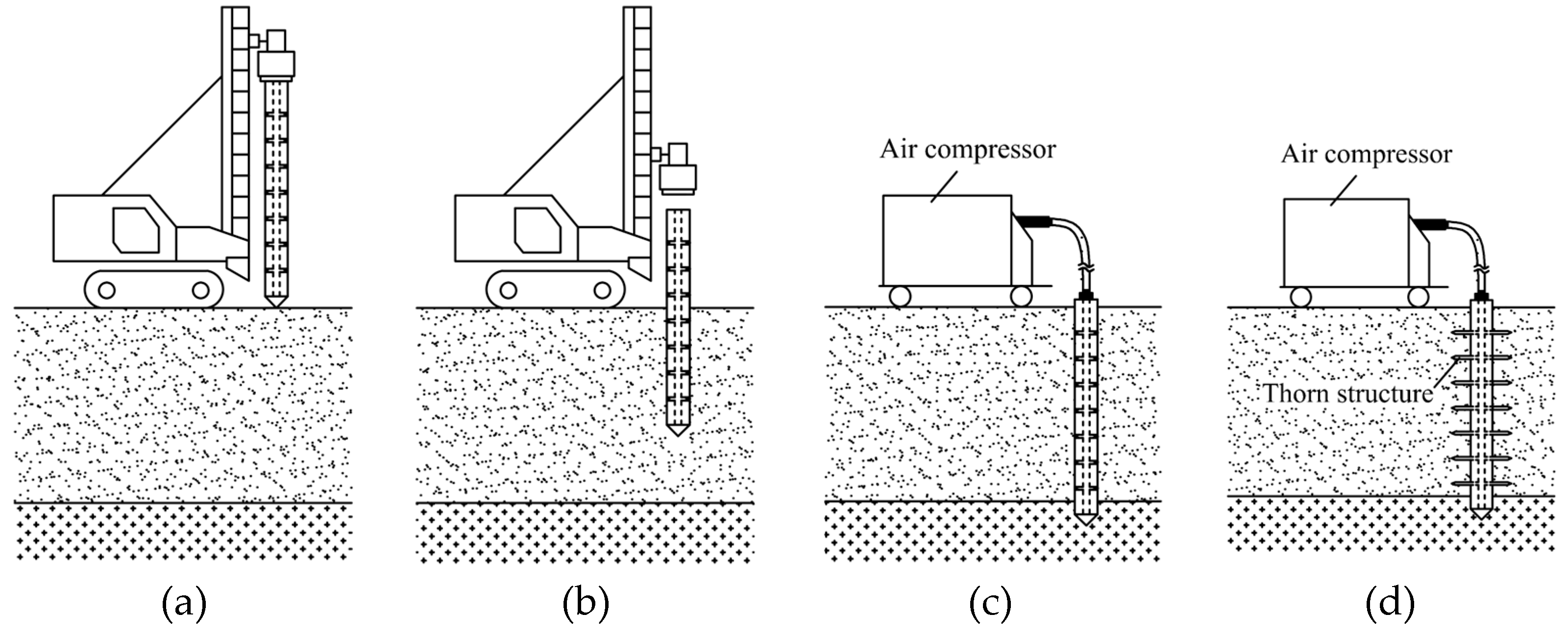
Figure 1. Construction process flow chart of prefabricated thorn pile. (a) Pile in place; (b) hammer the pile; (c) install apparatus; (d) push into thorns.
Buildings 15 03328 g001
Figure 2. Schematic diagram of the model (unit: m).
Buildings 15 03328 g002
Figure 3. Diagram of the thorn pile (unit: m).
Buildings 15 03328 g003
Figure 4. Grid cell model of the 3# pile. (a) Thorn pile; (b) soil; and (c) pile and soil assembly diagram.
Buildings 15 03328 g004
Figure 5. Stress and displacement nephograms after initial ground stress equilibrium. (a) Smooth pile S33; (b) Smooth pile U3; (c) 3# pile S33; and (d) 3# pile U3.
Buildings 15 03328 g005
Figure 6. Q-s curve of the pile top.
Buildings 15 03328 g006
Figure 7. Curve of the pile top settlement and taper at Q = 1651.7 kN.
Buildings 15 03328 g007
Figure 8. Relationship curve between the pile tip resistance and pile top settlement.
Buildings 15 03328 g008
Figure 9. Relationship between the pile tip resistance sharing ratio and pile top settlement.
Buildings 15 03328 g009
Figure 10. Relationship curve between the pile shaft resistance and pile top settlement.
Buildings 15 03328 g010
Figure 11. Relationship between the pile shaft resistance sharing ratio and pile top settlement.
Buildings 15 03328 g011
Figure 12. Axial force distribution of different thorn piles at Q = 1700 kN.
Buildings 15 03328 g012
Figure 13. Axial force distribution of the 5# pile with depth when Q = 700–4900 kN.
Buildings 15 03328 g013
Figure 14. Schematic diagram of pile–soil interaction (the red line represents the movement direction of soil particles). (a) Smooth pile; (b) Thorn pile.
Buildings 15 03328 g014
Figure 15. Displacement nephograms of different piles at s = 5 cm. (a) Smooth pile; (b) 1# pile; (c) 3# pile; and (d) 5# pile.
Buildings 15 03328 g015
Figure 16. Vertical displacement of soil around the pile along the horizontal path at Q = 1700 kN.
Buildings 15 03328 g016
Figure 17. Vertical displacement of pile side soil and the pile body at Q = 1700 kN.
Buildings 15 03328 g017
Figure 18. Curve of thorn tip resistance and pile top settlement.
Buildings 15 03328 g018
Figure 19. Curve of thorn friction resistance and pile top settlement.
Buildings 15 03328 g019
Figure 20. Curve of pile body friction resistance and pile top settlement.
Buildings 15 03328 g020
Figure 21. Bar chart of three-phase resistance increment and thorn taper.
Buildings 15 03328 g021
Table 1. Structure dimensions of the pile thorn.
TypePile Diameter
D (mm)
Thorn Length
l (mm)
d2
(mm)
d1
(mm)
d2/d1Taper
k = (d2d1)/l
Number
Smooth pile1000/////0# pile
Thorn pile50050.00 50.00 10.0%1# pile
56.95 42.71 0.752.8%2# pile
65.46 32.73 0.56.5%3# pile
75.59 18.90 0.2511.3%4# pile
81.09 10.14 0.12514.2%5# pile
Table 2. Mechanical parameters of materials.
TypeElastic Modulus
(Pa)
Poisson’s RatioDensity (kg/m3)Cohesion (Pa)Internal Friction Angle (φ°)Dilation Angle (°)
Silt3.6 × 1070.2518001600258
Pile body3.0 × 10100.22500///
Pile thorn2.1 × 10110.37850///
Disclaimer/Publisher’s Note: The statements, opinions and data contained in all publications are solely those of the individual author(s) and contributor(s) and not of MDPI and/or the editor(s). MDPI and/or the editor(s) disclaim responsibility for any injury to people or property resulting from any ideas, methods, instructions or products referred to in the content.