Article

New Insight into the Phenomenon of Buckling in Compressed Beams with Firm Support

by
Mikel Goñi
,
Faustino N. Gimena
and
José-Vicente Valdenebro
*
Department of Engineering, Campus Arrosadía, Public University of Navarre, 31006 Pamplona, Navarre, Spain
*
Author to whom correspondence should be addressed.
Buildings 2025, 15(18), 3279; https://doi.org/10.3390/buildings15183279
Submission received: 30 July 2025 / Revised: 1 September 2025 / Accepted: 9 September 2025 / Published: 11 September 2025
(This article belongs to the Section Building Structures)

Abstract

This work presents a new insight into the buckling phenomenon to approach the calculation of the compressed bar with the following firm supports: bi-pinned, bi-fixed, and fixed-pinned. Buckling is redefined as the result of second-order deformations in the real bar by gradually applying the compression load, thus dismissing Euler’s critical load. The analytical results are obtained from the differential equation of the directrix beam with sinusoidal deformation associated with each type of support. The bending moment is generated only by the compression load acting on the initial geometric imperfection. These analytical solutions are associated with first-order effects, applying the entire compressive load, and with second-order effects, applying the load gradually. The analytical solutions are continuous functions. In this paper, the Finite Transfer Method was applied to obtain numerical results. The bending moments, transverse displacements, and normal stresses are presented as the results. Beams with different initial imperfections in the directrix are studied: with sinusoidal deformation, with deformation produced by a specific transverse load, and with deformation produced by a uniform transverse load. The results obtained through the analytical expressions derived from the gradual application of the load are compared with those results obtained numerically when calculating the beam under second-order conditions. It is concluded that in structural practice, they are equivalent.

1. Introduction

The combination of normal force and bending moment appears in most beams that make up rigid structures, and even in pinned structures. This issue is inevitable in practice. Compressed real beams are always subject to compound bending effects. The maximum stress is obtained by adding the stresses due to the normal force and the bending moment. In the structural calculation of compressed beams, the influence of the bending moment depends on its relationship with the normal force. The way to measure the relative importance of both solicitations is to calculate their quotient or eccentricity. If it is very large, the normal force is irrelevant, and if it is very small, the bending moment is not important.
A real beam necessarily presents an initial eccentricity that depends both on the perfection of the construction and installation, and on the possibility of measuring it. Execution can be made more precise as long as imperfections can be measured. What cannot be verified cannot be demanded. Under traction load, the initial transverse displacement is reduced. On the other hand, under compression load, the initial transverse displacement is amplified, and this implies an increase in stress and deformation. In structural analysis, this bending deformation produced in the compressed beam is called buckling [1].
Currently, buckling is defined as a phenomenon of elastic instability that occurs in a compressed beam and is manifested by the appearance of displacements transverse to the direction of compression [2,3,4,5]. These displacements are not proportional to the loads applied. Although these displacements are insignificant, an increase in stress occurs due to the appearance of bending moments. The stresses generated by compression and bending effects have been coupled [6,7].
Leonhard Euler, in 1744, while developing examples of differential equations, gave a possible answer to the technical problem of buckling, where the bending moment was generated by compression load acting on the transverse displacements [8].
The solution to the problem begins by imagining an ideal beam with a perfectly centered force load. There is no difference in stress between an extended beam and a compressed one, except in the sign. But if the beam is slightly separated from its perfect shape, causing an initial eccentricity. In the extended beam, a bending moment appears that tends to make the beam straight. The less rigid it is, the straighter it will become, the lower the initial eccentricity, and the lower the resulting over stress. Hence, the advantage of cables, as traction elements, is that by dividing the section, the rigidity is minimized, making it easier for the stressed cable to be completely straight. On the contrary, when the beam is compressed, the bending moment resulting from the initial eccentricity tends to bend the beam with an additional transverse deformation [9].
In structural engineering, the question of stress increase in compression elements is a matter of great practical importance and great complexity. The study of the unsteady elastic behavior of compression beams has attracted the attention of numerous technicians and researchers [10,11,12,13,14,15,16,17,18,19,20,21,22]. The work of Emam and Lacarbonara [23] reviews models and solutions for buckling and post-buckling of beams available from the 1950s until practically the present day. Even so, the problem of buckling in its initial approach has not changed over time [24,25,26,27,28,29,30].
A beam is defined as a linear structural element with a straight guideline, manufactured without geometric imperfections, heterogeneities, or initial stresses. When an ideal beam is subjected solely to compression, longitudinal displacement occurs. The directrix of a real beam is a curved line, and its manufacture contains heterogeneities and initial stresses. In a real beam, the compression load generates both longitudinal and transverse displacements. The addition of transverse displacements to the initial geometric imperfection is called second-order effects. As the compression load increases, the transverse displacements increase more rapidly. Under this second-order effect, the superposition principle is not valid. Elastic instability is generated [31,32,33].
In the work of Gimena et al. [34], the calculation of the compression of the real beam was addressed under second-order effects by assimilating its directrix to a curved line. This second-order incremental analysis consists of dividing the load into increments; applying each load increment and obtaining the deformations and solicitations; modifying the shape of the directrix by adding the obtained transverse and longitudinal displacements; and recalculating the deformations and solicitations with the next load increment. It is an iterative process applicable until the load increments are exhausted.
This calculation of the real beam was performed with the entire compression load applied instantaneously, first-order analysis, and applying the compression load gradually, second-order analysis. Numerical values were obtained by applying the numerical procedure called the Finite Transfer Method [35,36,37,38]. The absence of elastic instability in a real compressed beam was demonstrated.
An analytical formulation was also obtained from the differential equation of the elastic sinusoidal deformation associated with the bi-pinned support, in which the bending moment is generated only by the initial imperfection.
This new approach to buckling resulted in a final expression for the beam’s deformation using second-order analysis. The values obtained using the new analytical formulation were compared with the numerical values.
In this paper, the calculation of the compressed beam with firm supports is addressed under a first- and second-order analysis, both analytically and numerically. The following firm supports are studied: bi-pinned, bi-fixed, fixed-pinned, and fixed-free. As a novelty, to obtain analytical results, the elastic equation associated with each type of support is used, where the bending moment is generated only by the initial sinusoidal imperfection. To perform the second-order analysis, the iterative procedure presented in the work by Gimena et al. [34] is used. The results are presented as bending moments, transverse displacements, and normal stresses under second-order analysis. Beams with different initial imperfections in the directrix are studied by the numerical procedure: with sinusoidal deformation and with deformation produced by a transverse load. The results of the compression beam calculations obtained using analytical expressions are compared with those obtained numerically. It is concluded that in structural practice, these results are equivalent, and that with this analysis, the buckling phenomenon is reproduced without the need to use the Euler critical load.

2. Compressed Beams with Firm Support and Sinusoidal Directrix

The analysis of a beam, in terms of its shape, is carried out by means of the great simplification of considering its curved directrix as straight. There is always a deviation or geometric imperfection from the directrix of the beam. Determining the true structural behavior of the beam would mean analyzing a piece with a curved directrix. In this section, the beam is analyzed with its usual hypotheses, but considering its sinusoidal directrix instead of a straight one [39].

2.1. Expressions of First-Order and Second-Order Effects

The sinusoidal shape of the beam’s directrix is associated with and adapted to the support. As can be seen in Figure 1, for each firm support (bi-pinned, bi-fixed, fixed-pinned, and fixed-free), the shape and equation of the beam’s directrix line are different.
The generic analytical notation of the initial sinusoidal directrix of the beam is as follows:
f z = η f m sin η 1 z / l + η 2 + η 3 z / l + η 4
where η , η 1 , η 2 , η 3 , η 4 are the parameters dependent on the support conditions and f m is the maximum initial imperfection or deformation.
Table 1 shows the values of the parameters of the generic sinusoidal equation of the beam’s directrix associated with the four firm supports.
For the real beam, the effect of the deviation or geometric imperfection of the directrix implies not considering its directrix as straight, even when the equilibrium and deformation equations of the ideal beam are applicable.
The differential expression of transverse displacement of the compression beam under a specific load at the end P can be noted as follows [34]:
d 4 δ 1 z d z 4 = 1 E I d 2 M 1 z d z 2 = P E I d 2 f z d z 2 = P E I η 1 / l 2 η f m sin η 1 z / l + η 2
The analytical result of Equation (2) is proportional to the initial sinusoidal directrix of the beam and represents the transverse displacement of the same. Its expression is as follows:
δ 1 z = P P k f z = P P k η f m sin η 1 z / l + η 2 + η 3 z / l + η 4
where P k = E I π 2 π / η 1 2 l 2 is noted as the traditional Euler’s critical load.
The displacement expressed in Equation (3) is continuous along the entire length of the directrix of the beam. The critical load does not produce any type of discontinuity.
In the structural model of the beam, the rotation is the derivative of the displacement if no indirect loads act and the deformation due to shear stress is not considered. In this case, and by means of these simplifications, the rotation is determined by the following expression:
θ 1 z = d δ 1 z d z = P η 1 P k l f z = P η 1 P k l η f m cos η 1 z / l + η 2 + η 3
Once the transverse displacement is known, the bending moment can be determined, whose equation is as follows:
M 1 z = P η f m sin η 1 z / l + η 2
The transverse displacement Equation (3), the rotation Equation (4), and the bending moment Equation (5) are first-order effects, i.e., the load has been applied instantaneously.
To determine the second-order deformation δ z = δ 2 z , load P must be applied gradually.
To do this, the load is divided into n equal parts, and the calculation is performed by applying the first increment of the same. From this calculation, the deformation produced is deduced, and a new directrix is generated. By repeating this calculation i times, the deformation is as follows:
δ z i = 1 + P n P K i 1 η f m sin η 1 z / l + η 2 + η 3 z / l + η 4
By applying the entire load gradually and taking this division to the limit, the second-order deformation is obtained, whose expression is as follows:
δ 2 z = [ e P P K 1 ] η f m sin η 1 z / l + η 2 + η 3 z / l + η 4
The first-order deformation Equation (3) and second-order Equation (7) represent continuous functions.
The second-order bending moment can be noted as follows:
M 2 z = P K [ e P P K 1 ] η f m sin η 1 z / l + η 2
There is no discontinuity in the formulation of the bending moment, as noted in the deformation equation under second-order analysis.

2.2. Numerical Example of a Compression Beam

The numerical analysis of the four beams presented above is performed under compression loading and firm support using the Finite Transfer Method [38].
To perform the structural calculation under first-order analysis, a computer program is used that applies the Finite Transfer Method to the initial sinusoidal directrix of the beam with the full compression load.
To obtain values under a second-order analysis, the load is divided into 10,000 equal parts. First, numerical design values are obtained on the initial geometry of the directrix with the first portion of the load. With these values, the new shape of the beam’s directrix is determined, and the numerical procedure is applied a second time. This process is iterated until the full load is applied. Therefore, a second-order analysis is performed on the real beam with a sinusoidal directrix.
A compressed steel beam with a hollow circular section ϕ 200.8 was chosen for the common analysis in construction (Figure 2).
Table 2 presents the shape and material characteristics of the type of beam studied.
In this structural analysis, the shear coefficients are considered to be zero. In addition to the geometric imperfection of the directrix, it is considered that the beam has no initial manufacturing stresses, that its material is homogeneous and isotropic, and that the section is absolutely constant. The load involved in the calculation represents the maximum load that this beam without imperfections, or an ideal beam, can support, and the calculation is performed without using safety coefficients to determine the strength of the material. The value of this load is P 0 = f y A = 1713 kN (with the elastic exhaustion limit stress being f y = 355 N / mm 2 ) [39]. The four firm support beams described in Equation (1) are analyzed with the values in the table. The initial maximum deformation f m is 5 mm, which represents an arrow-span ratio of l / 1000 . It is a common building tolerance in steel construction [40].
Table 3 presents the results of the first-order and second-order bending moments of these four firmly supported beams, obtained by the application of the Finite Transfer Method numerical process.
There is a variation between the values of the first- and second-order bending moments, which are 64.77% in the bi-pinned beam, 12.54% in the bi-fixed beam, 26.53% in the fixed-pinned beam, and 974.71% in the fixed-free beam. Table 4 shows the results of the first-order and second-order transverse displacements of the four firmly supported beams, obtained by applying the Finite Transfer Method.
The variation between the values of the first- and second-order transverse displacements is practically equal to the variation in the values of the bending moments. Bi-fixed support involves a smaller variation between first- and second-order effects than other types of support. In contrast, in fixed-free support, this variation between effects is greater.

2.3. Maximum Normal Stress of First- and Second-Order Effects

The highest normal stress of the beam occurs at the section where the absolute value of the bending moment is highest and at the furthest point from the centroid. Its value obtained by the analytical formulation’s Equations (5) and (8) for first- and second-order effects is as follows:
σ 1 P = P A + M 1 max W = P A + P K η f m W P P K ;   σ 2 P = P A + M 2 max W = P A + P K η f m W [ e P P K 1 ]
By analyzing the expressions in Equation (9), it is possible to detect the relationship between the stress produced by the first- and second-order bending moments. This relationship indicates that the increase in stress due to second-order effects e P P K 1 is greater than that due to first-order effects P P K . It is the second-order analysis that will determine the maximum load that a compressed beam can withstand until its elastic exhaustion.
It should be noted that the stress depends on the load, the initial geometric imperfection of the directrix, and the shape of the section. This stress must be less than that allowed by the beam material. Therefore, the expressions in Equation (9) are applicable at the structural design level.
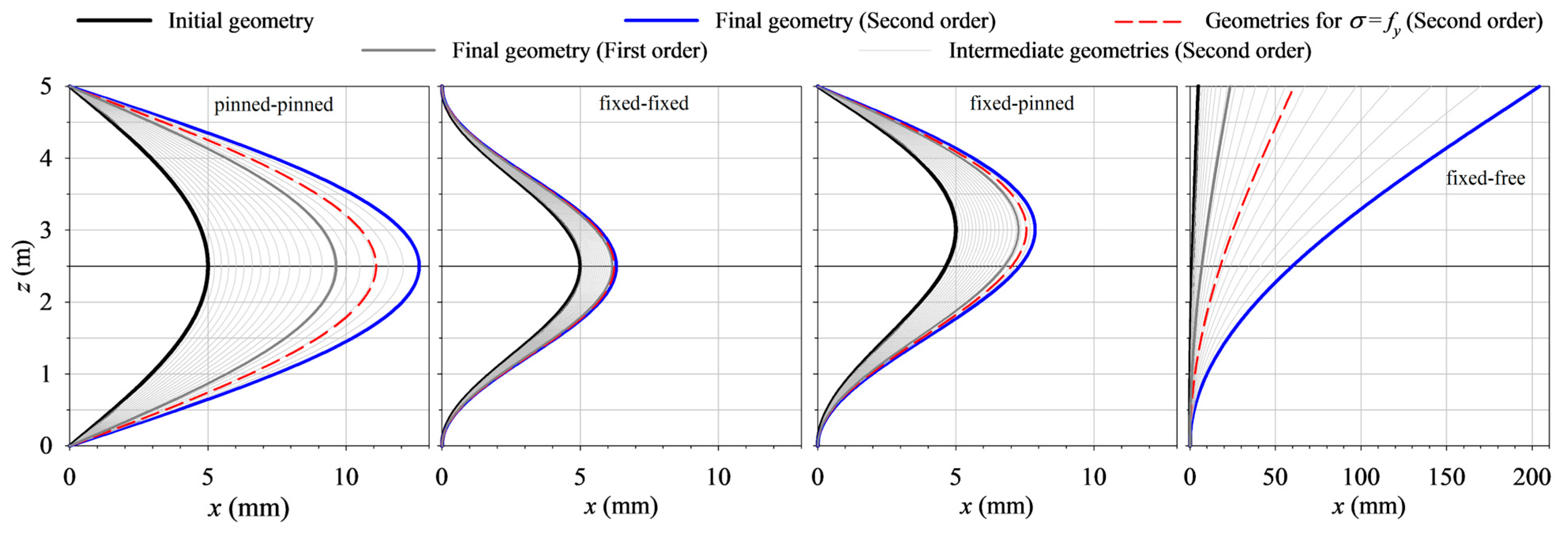
Figure 3 shows the initial geometry of the sinusoidal directrix of the compressed beam with firm support. The geometry acquired by the beam’s directrix under first- and second-order effects is also shown, and the final geometry of the directrix associated with the elastic exhaustion stress. The geometry of the directrix for second-order effects is included in Figure 3, associated with a percentage of the maximum exhaustion load for the ideal beam.
It can be observed in Figure 3 that although the maximum initial deformation of the beam is the same for the four firm supports, the geometry associated with the elastic exhaustion stress is totally different.
Under the load of elastic exhaustion, for the bi-pinned beam, the maximum initial deformation of 5 mm reaches a final deformation of 11.082 mm.
For the bi-fixed beam, the maximum final deformation is 6.222 mm, and for the fixed-pinned beam, it is 7.556 mm. In the fixed-free beam, the maximum final deformation occurs at the free end, and its value is 60.895 mm.

2.4. Analysis of the Type Beam with Different Sag-to-Span Ratios

A study of the behavior of the type beam is carried out, with a sinusoidal directrix and length l = 5 m, with different maximum initial deformations of 50 mm, 20 mm, 10 mm, 20/3 mm, and 5 mm or arrow-span ratios of l/100, l/250, l/500, l/750, and l/1000, respectively.
Table 5 shows the results obtained from the second-order effects, bending moment Equation (8) and transverse displacement Equation (7), both when applying the analytical expressions and the Finite Transfer Method, of the beams with firm support.
The values obtained by the analytical formulas are equivalent to the values obtained by the numerical procedure. It can be observed in Table 5 that the resulting values of the bending moments and the second-order transverse displacements are proportional to the initial deformation.
Table 6 shows the values of the punctual loads, P2, to reach the elastic exhaustion limit in beams with firm support and with sinusoidal imperfection under different initial deformations. The percentage of these punctual loads versus the elastic exhaustion load of the beam without initial imperfection is also presented.
It can be observed that the elastic exhaustion load depends on the initial deformation. There is no load that produces instability in the beam. In the case of the beam with fixed-free support with high slenderness, the exhaustion load, in the cases presented, is higher than the traditional critical load.
Figure 4 shows the graphs of normalized stresses with respect to the exhaustion load, in the ideal beam and in the beams with the arrow-span ratio of l/250 and l/1000.
Figure 4 shows that the stress in the ideal beam with respect to the exhaustion load is linear. In the case of the type beam, the stress depends on the initial imperfection and the type of support, and it is easy to determine from the graph the percentage of the exhaustion load.

3. Compressed Beams with Firm Support and Initial Deformation Generated by Transverse Loads

As discussed in the previous section, the directrix of the real beam always has a deviation or geometric imperfection. This initial deformation produced in the directrix can be due to different causes, such as imperfections in the construction or the influence of transverse loads. In this section, the transverse load is analyzed in the geometric imperfection of the straight directrix of the beam, and is compared with the analytical results offered when the initial deformation is sinusoidal.
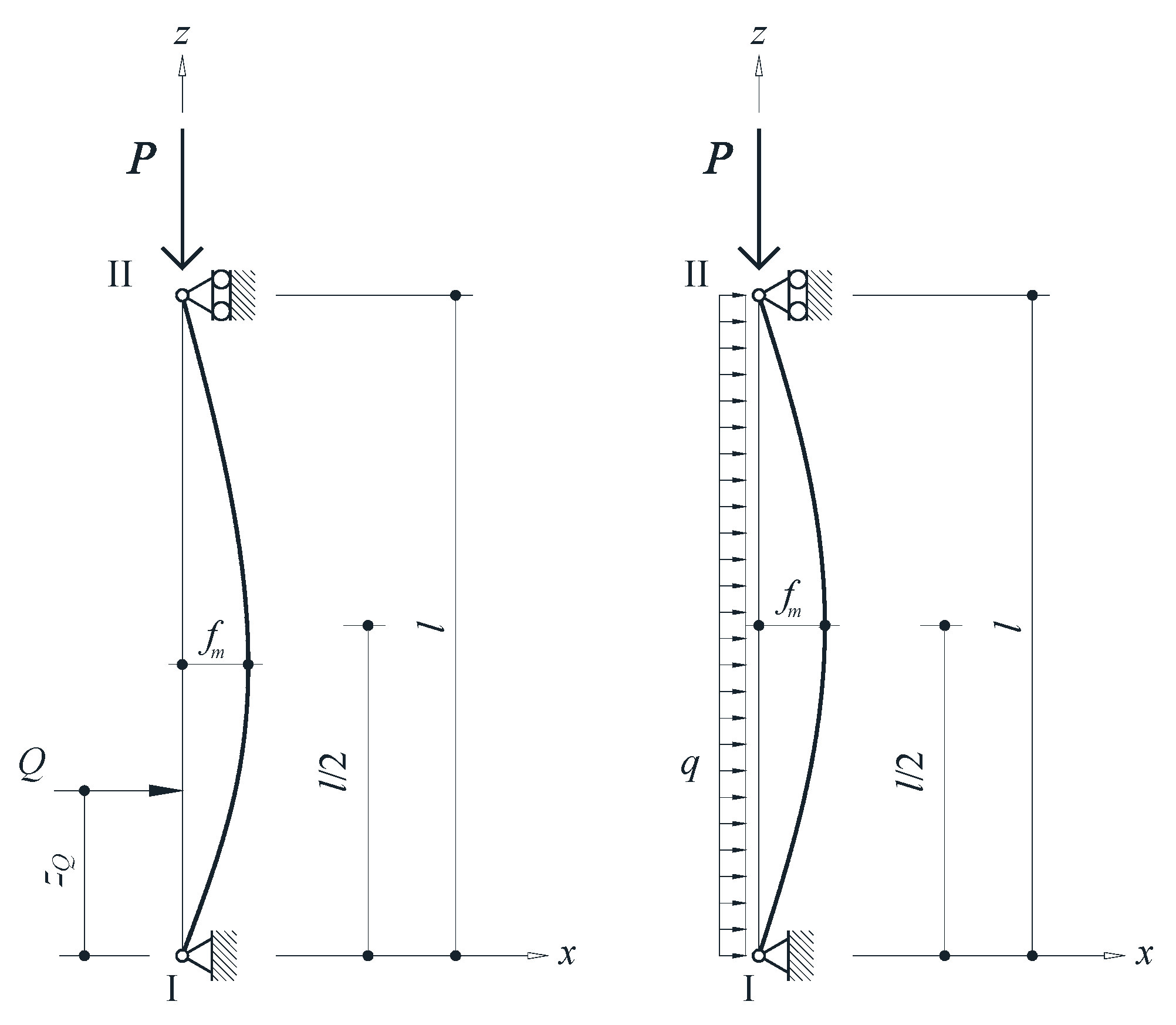
Figure 5 shows the initial deformation of the directrix due to punctual and uniform transverse loads. These two cases are discussed in the following sections.

3.1. Beams with Initial Deformation Produced by a Punctual Transverse Load

The second-order effects that occur in the type beam are analyzed, with an initial deformation of the directrix due to a punctual transverse load Q . The maximum deformation in the initial directrix, before gradually applying the punctual compression load P 0 = 1713 kN , occurs at the point z f m , and its value is 5 mm. Table 7 shows that the point of application of the punctual transverse load Q does not have to coincide with the point of maximum initial deformation z f m .
In the isostatic case of the bi-pinned beam, for all the initial geometries due to a transverse punctual load, there is very little variation in the value of the maximum bending moment. For the fixed-free beam, the maximum bending moment always occurs at the fixed point, and there are significant differences in the initial deformations. In the two cases of hyperstatic beams, bi-fixed support and fixed-pined support, the initial shapes of the directrix due to the transverse load are very different. This implies a large variation in the value of the maximum bending moment.
Figure 6 shows three graphs similar to influence lines. The horizontal axis represents the point of application of the punctual transverse load that generates the initial deformation of the directrix. This non-unitary load causes the maximum initial deformation to be 5 mm. The vertical axes represent the maximum bending moments in absolute value, the maximum transverse displacements, and the maximum stresses. In each of the three graphs, the four functions associated with each of the four firm supports are represented. Also, the analytical functions associated with each type of support are represented.
It can be observed that the values associated with the fixed-free support are much higher than the values associated with other supports.
Analyzing Figure 6, it can be noted that it is in the compressed beam with bi-pinned support where the influence lines are equivalent to those presented analytically for a sinusoidal initial deformation.

3.2. Beam with Initial Deformation Produced by a Uniform and Constant Transverse Load

The second-order effects that occur in the type beam are analyzed, with an initial deformation of the directrix due to a uniform and constant transverse load. The value of the maximum deformation in the initial directrix is 5 mm, before gradually applying the punctual compression load P 0 = 1713 kN .
Table 8 shows the highest transverse displacement values, the minimum and maximum bending moments, and the maximum stresses in the type beam with an initial directrix generated by a punctual transverse load and by a uniform transverse load, and with a sinusoidal initial directrix. These second-order values are presented for the four cases of firm support. The position of the punctual transverse load is the one that makes the point of maximum initial transverse deformation coincide with the point of maximum sinusoidal deformation.
It can be seen by analyzing the values in Table 8 that the results for each type of initial directrix and type of support are practically equivalent.
To determine the second-order values of the transverse displacements, bending moments, and stresses in a real beam with firm support, the formulas noted in Equations (7)–(9) can be applied. The application of the formulas facilitates the possibility of obtaining results of second-order effects in real beams, knowing the value of the maximum initial deformation. It is verified that the initial geometry of the beam’s directrix can be approximated to the sinusoidal line associated with the support as stated in the regulations [39,40].
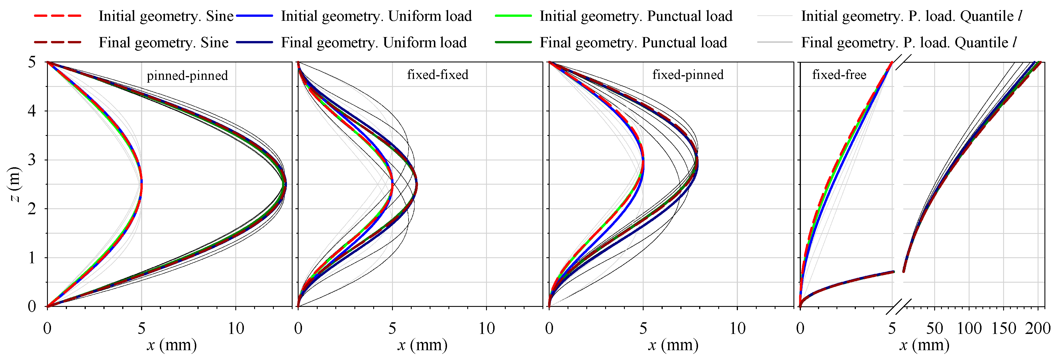
Figure 7 shows four graphs of the beam’s directrix geometry associated with the firm support conditions. Each graph represents the initial and final geometry of the real beam’s directrix. This final geometry has been obtained by adding the second-order deformation to the initial geometry. For each support, different directrix geometries are represented: those generated by transverse, punctual, and uniform loads, and sinusoidal ones.
If we start from similar directrices for the real beam, we obtain in turn very similar final geometries. Therefore, similar values of the bending moments and the maximum admissible stress.
In both cases of isostatic beams, the difference between the initial and final geometry is greater. This difference is reduced in both cases of hyperstatic beams.
From the above, it is concluded that for the calculation of vertical structural elements subjected to compression, a sinusoidal initial imperfection with a sag-to-span ratio of 1/1000 can be used.

4. Conclusions

From the differential expression of the transverse displacement of the real beam under compression, Equation (2), under a punctual load, and with initial sinusoidal imperfection, the analytical formulations of the transverse deformation Equation (7) and the bending moment Equation (8) have been deduced. These two expressions are associated with second-order effects and represent continuous functions at all their points. It is concluded that the collapse of the structure does not occur under any specific critical load, but is due to the exhaustion that originates in the beam due to the increase in the bending moments. The second-order analysis, consisting of the gradual application of the load, is the one that will determine the maximum point load that a compressed beam can withstand until reaching the exhaustion stress, Equation (9).
From the differential expression of the elastica in the real compressed beam with an initial sinusoidal imperfection, Equation (2), the analytical formulations associated with the transverse deformation, Equation (7), and the bending moment, Equation (8), have been deduced.
These two analytical expressions, obtained under second-order analysis, represent functions without discontinuities. It is concluded that under no specific critical load does the structure collapse. This collapse is due to the fatigue that originates in the beam due to the increase in bending moments. The second-order analysis, consisting of the gradual application of the load, will determine the maximum point load that a compressed beam can withstand until reaching the fatigue stress expressed in Equation (9).
These real beams with firm support: bi-pinned, bi-fixed, fixed-pinned, and fixed-free, under the first- and second-order analyses, have the same expressions to obtain the transverse deformation, the bending moment, and the maximum normal stress.
It should be noted that the ratio of first- and second-order effects is P P K divided by e P P K 1 .
Therefore, the second-order analysis is the one that will determine both the maximum load that a compressed beam can withstand until its elastic exhaustion and the maximum transverse deformation.
It should be noted that we need to know the initial imperfection of the real beam’s directrix to determine the effects it has on it. The exhaustion load of a compressed beam depends on its shape, length, initial imperfection of the directrix, and its cross-section and material.
To determine its value, the numerical procedure Finite Transfer Method can be used, using the gradual application of the load developed in this work.
In structural practice, the results obtained for different initial geometries of the directrix are equivalent: sinusoidal line and lines generated by transverse, punctual, and uniform loads. This statement can be verified by analyzing the values in Table 8.
Also, as can be seen from Figure 7, if we start from similar initial directrices for the real beam, we obtain very similar final geometries. Therefore, we obtain equivalent values for the bending moments and the maximum admissible stress.
By applying the expression noted in Equation (9) associated with second-order effects, the maximum punctual load of exhaustion of a real compressed beam can be determined accurately enough.

Author Contributions

Conceptualization, M.G., F.N.G. and J.-V.V.; methodology, M.G., F.N.G. and J.-V.V.; software, M.G.; validation, M.G., F.N.G. and J.-V.V.; formal analysis, M.G., F.N.G. and J.-V.V.; investigation, M.G., F.N.G. and J.-V.V.; writing—original draft preparation, F.N.G.; writing—review and editing, M.G. and J.-V.V.; visualization, M.G., F.N.G. and J.-V.V. All authors have read and agreed to the published version of the manuscript.

Funding

This research received no external funding.

Data Availability Statement

Data sharing is not applicable.

Conflicts of Interest

The authors declare no conflicts of interest.

References

  1. Lahuerta Vargas, J. Estructuras de Edificación; Escuela Técnica Superior de Arquitectura de la Universidad de Navarra: Pamplona, Spain, 1985. [Google Scholar]
  2. Ortiz Berrocal, L. Resistencia de Materiales; McGraw-Hill: Madrid, Spain, 2007. [Google Scholar]
  3. Ikeda, K.; Murota, K. Imperfect Bifurcation in Structures and Materials; Springer: New York, NY, USA, 2002. [Google Scholar]
  4. Areiza-Hurtado, M.; Aristizábal-Ochoa, J.D. Second-order analysis of a beam-column on elastic foundation partially restrained axially with initial deflections and semirigid connections. Structures 2019, 20, 134–146. [Google Scholar] [CrossRef]
  5. Ikeda, K.; Murota, K. Bifurcation and Buckling in Structures; CRC Press: Boca Raton, FL, USA, 2021. [Google Scholar]
  6. Love, A.E.H. A Treatise on the Mathematical Theory of Elasticity; Dover Publications Inc.: Garden City, NY, USA, 1944. [Google Scholar]
  7. Horton, W.H.; Bailey, S.C.; McQuilkin, B.H. An introduction to instability. In Proceedings of the ASTM Annual Meeting, Atlantic City, NJ, USA, June 1966. Stanford University Paper No. 219. [Google Scholar]
  8. Euler, L. Sur la force des colonnes. Mémoires L’acad. Sci. Berl. 1759, 13, 252–282. [Google Scholar]
  9. Aroca Hernández-Ros, R. Flexión Compuesta y Pandeo en Barras Rectas. In Cuadernos de Apoyo a la Docencia del Instituto Juan de Herrera; Instituto Juan de Herrera, ETS de Arquitectura: Madrid, Spain, 2001. [Google Scholar]
  10. Todhunter, I. A History of the Theory of Elasticity and of the Strength of Materials from Galilei to the Present Time; The Syndics of the University Press: Cambridge, UK, 1893. [Google Scholar]
  11. Timoshenko, S.P. History of Strength of Materials; McGraw-Hill: Tokyo, Japan, 1953. [Google Scholar]
  12. Komarakul-na-Nakorn, A.; Arora, J.S. Stability criteria: A review. Comput. Struct. 1990, 37, 35–49. [Google Scholar] [CrossRef]
  13. Johnston, B.G. Column buckling theory: Historic highlights. J. Struct. Eng. 1993, 109, 2086–2096. [Google Scholar] [CrossRef]
  14. Elishakoff, I. Uncertain buckling: Its past, present and future. Int. J. Solids Struct. 2000, 37, 6869–6889. [Google Scholar] [CrossRef]
  15. Elishakoff, I. Essay on the Contributors to the Elastic Stability Theory. Meccanica 2005, 40, 75–110. [Google Scholar] [CrossRef]
  16. Ortega, M.A.; Romero, J.L.; de la Rosa, E. Un estudio histórico del problema de las piezas prismáticas rectas sometidas a compresión. parte I. Inf. Constr. 2007, 59, 69–81. [Google Scholar]
  17. Ortega, M.A.; Romero, J.L.; de la Rosa, E. Un estudio histórico del problema de las piezas prismáticas rectas sometidas a compresión. parte II. Inf. Constr. 2007, 59, 61–71. [Google Scholar]
  18. Melissianos, V.E.; Gantes, C.J. Buckling and post-buckling behavior of beams with internal flexible joints resting on elastic foundation modeling buried pipelines. Structures 2016, 7, 138–152. [Google Scholar] [CrossRef]
  19. Shen, C.H.; Yu, H.S.; Wang, X.J.; Tang, K.; Asiedu-Kwakyewaa, C.; Zhang, H.Y. Determining the critical buckling load of locally stiffened U-shaped steel sheet pile using dynamic correlation coefficient method. Sci. Rep. 2022, 12, 12970. [Google Scholar] [CrossRef]
  20. Rodrigues, M.A.C.; Burgos, R.B.; Martha, L.F.C.R. A unified approach to the Timoshenko 3D beam-column element tangent stiffness matrix considering higher-order terms in the strain tensor and large rotations. Int. J. Solids Struct. 2021, 222, 111003. [Google Scholar] [CrossRef]
  21. Sun, Y.; Song, D.A.; Sun, S.; Guo, Y. Behavior of large-size and high-strength steel angle subjected to eccentric load. Structures 2023, 57, 105161. [Google Scholar] [CrossRef]
  22. Barszcz, A.M.; Giżejowski, M.A.; Papangelis, J.P. Investigations into the Flexural-Torsional Buckling Behavior of Steel Open-Section Beam-Columns. Buildings 2023, 13, 307. [Google Scholar] [CrossRef]
  23. Emam, S.; Lacarbonara, W. A review on buckling and postbuckling of thin elastic beams. Eur. J. Mech. A/Solids 2022, 92, 104449. [Google Scholar] [CrossRef]
  24. Timoshenko, S.P.; Gere, J.M. Theory of Elastic Stability; McGraw-Hill: Tokyo, Japan, 1961. [Google Scholar]
  25. Zeeman, E.C. Euler Buckling. In Structural Stability, the Theory of Catastrophes, and Applications in the Sciences; Springer: Berlin, Germany, 1976. [Google Scholar]
  26. Trahair, N.S.; Bradford, M.A.; Nethercot, D.; Gardner, L. The Behaviour and Design of Steel Structures to EC3; Springer: Berlin, Germany, 2008. [Google Scholar]
  27. Luo, L.; Zhang, Y. A new method for establishing the total potential energy equations of steel members based on the principle of virtual work. Structures 2023, 52, 904–920. [Google Scholar] [CrossRef]
  28. Falope, F.O.; Lanzoni, L.; Tarantino, A.M. Lateral buckling of the compressed edge of a beam under finite bending. Eur. J. Mech. A/Solids 2024, 107, 105373. [Google Scholar] [CrossRef]
  29. Hussein, A.B. Structural behaviour of built-up I-shaped CFS columns. Sci. Rep. 2024, 14, 25628. [Google Scholar] [CrossRef]
  30. Botis, M.; Imre, L.; Conțiu, M. Numerical method of increasing the critical buckling load for straight beam-type elements with variable cross-sections. Appl. Sci. 2023, 13, 1460. [Google Scholar] [CrossRef]
  31. Trahair, N.S. Flexural–Torsional Buckling of Structures; CRC Press: Boca Raton, FL, USA, 1993. [Google Scholar]
  32. Yang, Y.B.; Kuo, S.R. Theory and Analysis of Nonlinear Framed Structures; Prentice Hall: Singapore, 1994. [Google Scholar]
  33. Eslami, M.R. Buckling and Postbuckling of Beams, Plates, and Shells; Springer International Publishing: Cham, Switzerland, 2018. [Google Scholar]
  34. Gimena, F.N.; Goñi, M.; Gonzaga, P.; Valdenebro, J.V. Alternative approach to the buckling phenomenon by means of a second-order incremental analysis. Sci. Rep. 2023, 13, 16146. [Google Scholar] [CrossRef]
  35. Gimena, F.N.; Gonzaga, P.; Gimena, L. Numerical transfer-method with boundary conditions for arbitrary curved beam elements. Eng. Anal. Bound. Elem. 2009, 33, 249–257. [Google Scholar] [CrossRef]
  36. Sarria, F.; Gimena, F.N.; Gonzaga, P.; Goñi, M.; Gimena, L. Formulation and Solution of Curved Beams with Elastic Supports. Teh. Vjesn. 2018, 25 (Suppl. S1), 56–65. [Google Scholar] [CrossRef]
  37. Gimena, F.N.; Gonzaga, P.; Valdenebro, J.V.; Goñi, M.; Reyes-Rubiano, L.S. Curved beam through matrices associated with support conditions. Struct. Eng. Mech. 2020, 76, 395–412. [Google Scholar] [CrossRef]
  38. Gimena, L.; Gonzaga, P.; Gimena, F.N. Boundary equations in the finite transfer method for solving differential equation systems. Appl. Math. Model. 2014, 38, 2648–2660. [Google Scholar] [CrossRef]
  39. European Committee for Standardization. Eurocode 3: Design of Steel Structures-Part 1-1: General Rules and Rules for Buildings; European Committee for Standardization: Brussels, Belgium, 2005. [Google Scholar]
  40. Real Decreto 470/2021, de 29 de Junio, por el que se Aprueba el Código Estructural. Available online: https://www.boe.es/eli/es/rd/2021/06/29/470 (accessed on 10 September 2025).
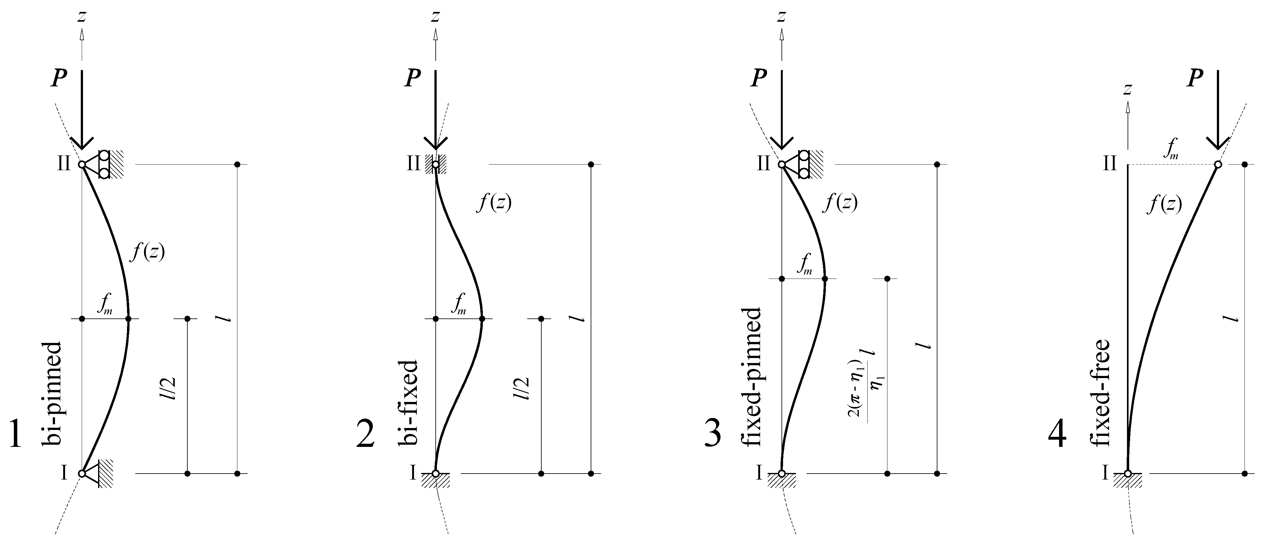
Figure 1. Shape of the sinusoidal directrix of the beam associated with each firm support: (1) bi-pinned, (2) bi-fixed, (3) fixed-pinned, and (4) fixed-free.
Buildings 15 03279 g001
Figure 2. Type beam with bi-pinned sinusoidal directrix.
Buildings 15 03279 g002
Figure 3. Initial and final geometry of the sinusoidal directrix of the type beam with firm support.
Buildings 15 03279 g003
Figure 4. Normalized stresses with respect to the exhaustion load in the ideal beam and other beam types.
Buildings 15 03279 g004
Figure 5. Initial form of the directrix under punctual and uniform transverse loads.
Buildings 15 03279 g005
Figure 6. Influence lines of the maximum bending moments in absolute value, the maximum transverse displacements, and the maximum stresses.
Buildings 15 03279 g006
Figure 7. Initial and final geometries of the directrix of the real beam with firm support.
Buildings 15 03279 g007
Table 1. Values of the parameters of the sinusoidal equation of the beam directrix associated with the firm support.
ηηηηη
bi-pinned−1ππ00
bi-fixed−0.52ππ/20−1
fixed-pinned−0.732644134.493409471.789775840.97611964−0.97611964
η1/(2πsin(η1))η1 + tan(2πη1) = 02πη1sin(2πη1)sin(η1)
fixed-free−1π/2π/20−1
Table 2. Shape and material characteristics of the type beam.
Beaml
(m)
fm
(mm)
SteelE
(kN/mm2)
G
(kN/mm2)
55S35521081
Circular
hollow sections
de
(mm)
di
(mm)
A
(cm2)
W
(cm3)
I = Ib = Iy
(cm4)
ϕ200.820018448.25222.742227.44
Table 3. First- and second-order bending moments of the standard beam with firm support.
My
(kN·m)
Bi-PinnedBi-FixedFixed-PinnedFixed-Free
z
(m)
First
Order
Second
Order
First
Order
Second
Order
First
Order
Second
Order
First
Order
Second
Order
00.000.004.284.826.137.758.5792.05
0.625−3.28−5.403.033.414.465.648.4090.28
1.25−6.06−9.980.000.001.421.807.9185.04
1.875−7.91−13.04−3.03−3.41−2.05−2.607.1276.54
2.5−8.57−14.11−4.28−4.82−4.90−6.196.0665.09
3.125−7.91−13.04−3.03−3.41−6.23−7.894.7651.14
3.25−7.63−12.57−2.52−2.83−6.28−7.944.4848.10
3.75−6.06−9.980.000.00−5.66−7.163.2835.23
4.375−3.28−5.403.033.41−3.34−4.231.6717.96
50.000.004.284.820.000.000.000.00
Table 4. First- and second-order transverse displacement of the type beam with firm support.
My
(kN·m)
Bi-PinnedBi-FixedFixed-PinnedFixed-Free
z
(m)
First
Order
Second
Order
First
Order
Second
Order
First
Order
Second
Order
First
Order
Second
Order
00.000.000.000.000.000.000.000.00
0.6251.772.920.170.190.240.300.363.83
1.253.275.390.580.650.841.061.4115.16
1.8754.287.050.981.111.551.963.1333.55
2.54.637.631.151.302.102.665.4358.31
3.014.397.241.041.172.262.867.6982.56
3.1254.287.050.981.112.252.858.2488.47
3.753.275.390.580.651.902.4011.45122.87
4.3751.772.920.170.191.081.3714.93160.20
50.000.000.000.000.000.0018.55199.02
Table 5. Second-order effects of the type beam with firm support and different initial deformations.
Second-OrderBi-PinnedBi-FixedFixed-PinnedFixed-Free
My
(kN.m)
δx
(mm)
My
(kN.m)
δx
(mm)
My
(kN.m)
δx
(mm)
My
(kN.m)
δx
(mm)
l/100analytical−141.1476.43−48.2013.05−79.4028.69−920.511993.91
numeric−141.1176.22−48.2012.96−79.4028.58898.781857.41
l/250analytical−56.4530.57−19.285.22−31.7611.48−368.21797.56
numeric−56.5330.62−19.285.18−31.7611.43366.55787.50
l/500analytical−28.2315.29−9.642.61−15.885.74−184.10398.78
numeric−28.2315.26−9.642.59−15.885.72183.80397.17
l/750analytical−18.8210.19−6.431.74−10.593.83−122.74265.85
numeric−18.8210.17−6.431.73−10.593.81122.60265.20
l/1000analytical−14.117.64−4.821.31−7.942.87−92.05199.39
numeric−14.117.63−4.821.30−7.942.8691.96199.02
Table 6. Elastic exhaustion loads P2 of the type beam with firm support and different initial deformations.
Second
Order
Bi-PinnedBi-FixedFixed-PinnedFixed-Free
P2
(kN)
P2/P0
(%)
P2
(kN)
P2/P0
(%)
P2
(kN)
P2/P0
(%)
P2
(kN)
P2/P0
(%)
l/100735.0742.91%1081.9763.16%903.2752.73%553.7432.32%
l/2501078.4262.95%1383.4480.76%1244.9572.67%794.6346.39%
l/5001302.9876.06%1529.0489.26%1435.8083.82%979.1257.16%
l/7501408.0582.20%1585.3592.55%1515.7288.48%1083.1963.23%
l/10001469.7385.80%1615.2694.29%1559.8091.05%1154.0267.37%
Table 7. Points of maximum initial deformation and second-order moments of the directrix type beam generated by a punctual transverse load with firm support.
zQ
(m)
Bi-PinnedBi-FixedFixed-PinnedFixed-Free
z (fm)
(m)
|MyMax|
(kN.m)
z (fm)
(m)
|MyMax|
(kN.m)
z (fm)
(m)
|MyMax|
(kN.m)
z (fm)
(m)
|MyMax|
(kN.m)
02.11314.071.6678.202.11310.245.00076.39
0.252.11714.071.7247.832.16310.015.00077.50
0.52.12814.071.7867.452.2159.785.00078.58
0.752.14614.071.8527.092.2699.555.00079.61
12.17214.061.9236.732.3279.325.00080.61
1.252.20514.062.0006.382.3899.095.00081.57
1.52.24614.052.0836.042.4548.875.00082.49
1.752.29614.052.1745.712.5248.655.00083.37
22.35414.042.2735.402.5988.445.00084.20
2.252.42214.042.3815.102.6788.255.00085.00
2.52.50014.042.5004.812.7648.075.00085.75
2.752.57814.042.6195.102.8577.915.00086.45
32.64614.042.7275.402.9587.805.00087.11
3.252.70414.052.8265.713.0087.985.00087.73
3.52.75414.052.9176.043.0508.135.00088.30
3.752.79514.063.0006.383.1278.255.00088.82
42.82814.063.0776.733.1918.345.00089.30
4.252.85414.073.1487.093.2438.415.00089.74
4.52.87214.073.2147.453.2838.465.00090.13
4.752.88314.073.2767.833.3118.495.00090.48
52.88714.073.3338.203.3288.505.00090.79
Table 8. Maximum transverse displacements, minimum and maximum bending moments, and maximum stresses of the initial directrix type beam generated by a uniform, punctual transverse load, and a sinusoidal directrix with firm support.
Initial Directrix Shape
Second
Order
Firm
Support
Punctual Transverse Load zQ(sin)Uniform
Transverse Load
Sinusoidal
(Numerical)
Sinusoidal
(Analytical)
bi-pinned7.6567.5257.6287.643
δxbi-fixed1.2781.2781.2961.305
(mm)fixed-pinned2.8832.8202.8582.869
fixed-free190.174196.172199.015199.391
bi-pinned−14.13−14.04−14.11−14.11
MyMinbi-fixed−4.52−4.81−4.82−4.82
(kN·m)fixed-pinned−7.02−7.90−7.94−7.94
fixed-free0.000.000.000.00
bi-pinned0.000.000.000.00
MyMaxbi-fixed5.114.814.824.82
(kN·m)fixed-pinned8.497.717.757.75
fixed-free88.3090.7991.9692.05
bi-pinned418.45418.02418.36418.36
σMaxbi-fixed377.92376.61376.64376.64
(N/mm2)fixed-pinned393.135390.459390.645390.646
fixed-free751.401762.573767.87768.26
Disclaimer/Publisher’s Note: The statements, opinions and data contained in all publications are solely those of the individual author(s) and contributor(s) and not of MDPI and/or the editor(s). MDPI and/or the editor(s) disclaim responsibility for any injury to people or property resulting from any ideas, methods, instructions or products referred to in the content.