Abstract
Since statistics show a growing trend in blindness and visual impairment, the development of navigation systems supporting Blind and Visually Impaired People (BVIP) must be urgently addressed. Guiding BVIP to a desired destination across indoor and outdoor settings without relying on a pre-installed infrastructure is an open challenge. While numerous solutions have been proposed by researchers in recent decades, a comprehensive navigation system that can support BVIP mobility in mixed and unprepared environments is still missing. This study proposes a novel navigation system that enables BVIP to request directions and be guided to a desired destination across heterogeneous and unprepared settings. To achieve this, the system applies Computer Vision (CV)—namely an integrated Structure from Motion (SfM) pipeline—for tracking the user and exploits Building Information Modelling (BIM) semantics for planning the reference path to reach the destination. Audio Augmented Reality (AAR) technology is adopted for directional guidance delivery due to its intuitive and non-intrusive nature, which allows seamless integration with traditional mobility aids (e.g., white canes or guide dogs). The developed system was tested on a university campus to assess its performance during both path planning and navigation tasks, the latter involving users in both blindfolded and sighted conditions. Quantitative results indicate that the system computed paths in about 10 milliseconds and effectively guided blindfolded users to their destination, achieving performance comparable to that of sighted users. Remarkably, users in blindfolded conditions completed navigation tests with an average deviation from the reference path within the 0.60-meter shoulder width threshold in 100% of the trials, compared to 75% of the tests conducted by sighted users. These findings demonstrate the system’s accuracy in maintaining navigational alignment within acceptable human spatial tolerances. The proposed approach contributes to the advancement of BVIP assistive technologies by enabling scalable, infrastructure-free navigation across heterogeneous environments.
1. Introduction
According to the World Health Organization (WHO), approximately 2.2 billion individuals globally suffer from visual impairment or low vision, a figure that increases by about 2 million every decade. Of these, at least 1 billion experience visual impairment, while the remaining 1.2 billion live with low vision [1]. Vision is widely regarded as one of the most critical human senses, as it plays a fundamental role in spatial perception and environmental understanding. It enables individuals to interpret the layout of an environment and locate specific destinations.
While Blind and Visually Impaired People (BVIP) may develop orientation strategies for familiar places, navigating unknown environments becomes considerably more difficult, especially when environments are mixed, involving both indoor and outdoor spaces. Transitions between such settings introduce abrupt changes in spatial structure, sensory cues, and technological reliability. For instance, the shift from outdoor to indoor settings is often accompanied by a loss of GNSS (Global Navigation Satellite System) coverage, significant variations in acoustic environments, and the absence of standardized wayfinding infrastructure. These challenges become even more critical in complex environments, where the lack of adaptive, context-aware systems significantly increases the risk of disorientation. Examples are shopping malls, train stations, and airports, where frequent layout changes and environmental distractions further increase cognitive load and the likelihood of disorientation [2].
Moreover, many of the environments BVIP need to navigate are unprepared since they lack dedicated infrastructures required by conventional assistive navigation systems [3,4]. Preparing an environment for navigation purposes is labor-intensive and costly, involving extensive measurement, calibration, and maintenance. Furthermore, many users may not have the means, authority, or technical skills to customize public or shared environments to meet their needs. As a result, systems that depend on prior environmental setup present major barriers to widespread adoption.
In light of these challenges, ensuring reliable navigation across mixed and unprepared environments emerges as a fundamental requirement for navigation systems intended for BVIP [2]. However, to the best of the authors’ knowledge, no existing solution currently meets both the requirements simultaneously, leaving a significant portion of the BVIP population underserved. To address them, Hypotheses (Hs) and Research Questions (RQs) have been formulated to guide the development of a novel navigation system for BVIP.
H.1.
While seamless transitions between heterogeneous environments are common, current navigation systems for BVIP are typically specialized for either indoor or outdoor environments [2]. This underpins the following RQ.1:
RQ.1.
How can BVIP be effectively guided to a desired destination while seamlessly navigating across heterogeneous mixed environments?
H.2.
Installing the infrastructure that current navigation systems rely on is time-consuming, costly, and frequently unfeasible, thereby reducing the scalability and inclusivity of these systems [3,4]. This underpins the following RQ.2:
RQ.2.
What strategies can enable reliable navigation for BVIP in unprepared environments while avoiding the need to install a dedicated infrastructure?
H.3.
Assuming the feasibility of a navigation system for BVIP capable of operating in mixed and unprepared environments, its reliability in supporting users in reaching a target destination should be quantitatively evaluated and benchmarked against the performance of sighted individuals. This underpins the following RQ.3:
RQ.3.
What is the effectiveness of a navigation system that meets the requirements defined by the previous RQs?
This paper, extending the work presented at the 24th International Conference on Construction Applications of Virtual Reality (CONVR 2024), answers the RQs by proposing a novel navigation system for BVIP. The system is specifically designed to work both indoors and outdoors, enable seamless transitions across heterogeneous spatial contexts, and function independently of pre-installed infrastructure, thus supporting navigation in unprepared environments. To achieve these objectives, the proposed system integrates multiple enabling technologies to provide core functionalities, such as user pose tracking, reference path planning, and directional guidance delivery. Accurate user localization in mixed and unprepared environments is enabled by registration engines based on Computer Vision (CV). The reference path to the target destination is computed, on demand, by an engine leveraging semantics encoded in BIM models. Finally, Audio Augmented Reality (AAR) technology is employed to convey navigation instructions through intuitive spatialized audio cues. Experiments conducted on a university campus yielded highly promising results. The remainder of this paper is structured as follows. In Section 2, the scientific background is presented. Section 3 presents the methodology, describing the system architecture, while Section 4 focuses on system implementation. In Section 5, experiments and result discussions are reported, and Section 6 is devoted to conclusions. Finally, Appendix A reports the complete set of experimental results, including figures omitted from the main text.
2. Scientific Background
White canes are traditional and widely used navigation aids for BVIP. They allow users to directly sense the ground through tactile feedback, improve sensory awareness, and assist with obstacle detection, echolocation, and shore lining, helping users better understand their surroundings [2,5]. While cost-effective, reliable, and easy to use, white canes have some limitations. For instance, they cannot provide orientation in complex or unfamiliar environments, do not detect obstacles at head, trunk, or overhead levels, and require physical contact to identify obstacles. To address these limitations and improve BVIP mobility, several assistive solutions have been proposed over the years. Existing navigation systems can be grouped into two categories, namely Electronic Travel Aids (ETAs) and Electronic Orientation Aids (EOAs), supporting mobility and orientation respectively [3,6]. Mobility is the ability to travel from one place to another safely and efficiently, while orientation refers to the ability to recognize one’s current location and intended destination [5]. ETAs aid users in safely exploring their surroundings by providing obstacle detection support. EOAs, on the other hand, help users by identifying a route and delivering navigational instructions. Since this study focuses on enhancing BVIP mobility, current EOAs-based navigation systems will be analyzed in the following subsections with a focus on their key functionalities, such as user tracking, reference path planning, and directional guidance delivery [7].
2.1. User Tracking
Tracking user position and orientation is a preliminary task necessary to support BVIP mobility. Considering the wide range of sensing technologies applied for this purpose, existing EOAs navigation systems can be classified into vision-based and non-vision-based approaches [1,6]. Non-vision-based systems rely on various sensors to guide users along a safe path. Smartphone-based systems, for example, utilize technologies such as Near-Field Communication (NFC) [8], Infrared (IR) [9], Radio-Frequency Identification (RFID) [10], Ultra-Wideband (UWB) [11], Wireless Fidelity (Wi-Fi) [12], and Bluetooth Low-Energy (BLE) [13]. NFC-based systems provide contextual object and location information via smartphone apps and environmental tags [8]. They offer high accuracy but suffer from very short range (limited to centimeters), making tag detection challenging for BVIP. Other technologies, such as IR, RFID, UWB, Wi-Fi, and BLE, offer longer operating distances, ranging from several meters to dozens of meters. IR solutions detect nearby obstacles and guide users through auditory feedback [9]. RFID systems combine wearable or AR devices with passive tags to enable indoor localization and guidance [10]. However, IR- and RFID-based systems often incur high installation costs. BLE-based systems, while they can provide turn-by-turn navigation through beacon-based localization, suffer from significant localization errors, often spanning several meters, and require pre-installed beacons [13]. Wi-Fi-based methods enable user localization using existing infrastructure and signal processing techniques [12]. They are low-cost but not accurate and are sensitive to environmental changes. UWB, on the other hand, offers centimeter-level accuracy for real-time indoor positioning and can effectively penetrate obstacles such as walls, making it a strong option for positioning and orientation [11]. Still, their adoption is limited by the need for environment pre-configuration and specific infrastructure. Despite some advantages, non-vision-based systems are less frequently adopted, likely due to the requirement to pre-configure the environment by setting up specific infrastructure [6].
Vision-based systems, by contrast, rely on cameras and CV to interpret visual data [1,6]. An example is an indoor navigation system using ceiling-mounted IP cameras to track the user and send navigational instructions via a mobile device [14]. IP cameras require prior environmental preparation and are associated with high installation costs. Another solution is the wearable navigation system that applies visual SLAM based on RGB-D cameras [15]. Visual-SLAM (Simultaneous Localization and Mapping) integrated with RGB-D cameras shows great potential for localization and mapping, but it is prone to accumulating errors over time and distance, limiting its application to short-range scenarios. Some vision-based systems employ monocular cameras and focus on specific tasks. For example, RGB camera-based visual marker detection is applied as a line-following method for path guidance [16]. These systems, despite their applicability in both indoor and outdoor scenarios, require environmental preparation and manual route input. Exceptions to this are Structure-from-Motion-based (SfM) navigation assistants [17], which can operate in unprepared environments as they do not require special infrastructure. SfM is a CV technique that reconstructs a three-dimensional structure of a scene from a set of two-dimensional images. While classical SfM reconstruction approaches have been employed thus far in BVIP navigation assistants [17], recent advancements have introduced more robust SfM pipelines. In fact, recent developments propose deep-learning-based SfM approaches, notably employing Convolutional Neural Networks (CNNs) to extract and match, across provided images, feature points to be included in the 3D reconstructed model. This model, created once for each explored area, serves as the localization reference and is georeferenced by defining the geographic coordinates of at least three key feature/shot points [18]. Recent developments have demonstrated the applicability of this solution, even in low-light conditions, with only limited reductions in performance [19,20]. However, SfM requires image datasets for 3D reconstruction; while this may limit scalability, it does not involve significant efforts or technical skills for environment preparation. Despite their potential, the application of these techniques within assistive navigation systems for BVIP remains largely unexplored. ARCore-based navigation systems, originally reliant on visual-inertial SLAM techniques for user tracking, are known to experience drift over extended trajectories [21]. More recently, the introduction of the ARCore Geospatial API—a SfM-based solution powered by Google’s Visual Positioning System (VPS)—has shown promise in mitigating such drift issues. VPS leverages CV techniques to determine a device’s location based on visual data from Google Maps’ Street View images for localization [22]. VPS builds its localization model by using Deep Neural Networks (DNNs) to extract key visual features– such as the outlines of buildings or bridges—from Street View images, creating a highly scalable and rapidly searchable index. Although its performance may be affected, this solution is still applicable in low-light conditions. When the device attempts to localize itself, VPS compares the extracted features from the current view with those in the reference model. By leveraging Street View data from over 93 countries, the system has access to trillions of visual reference points, allowing for triangulation that significantly improves positional accuracy [23]. As already noted for the most advanced deep learning-based SfM approaches, ARCore Geospatial API presents strong potential for developing navigation systems for BVIP in areas where VPS coverage is available, although, to date, no academic studies have reported practical applications of Google’s VPS for BVIP navigation.
To conclude, both state-of-the-art deep learning-based Structure-from-Motion (SfM) approaches and the ARCore Geospatial API enable applicability in unprepared environments, meaning they do not require any preliminary infrastructure installation. However, when considered individually, neither guarantees the development of a navigation assistant that operates seamlessly across both indoor and outdoor settings. Specifically, while deep learning-based SfM can function in both indoor and outdoor contexts, its scalability in large-scale outdoor environments is limited due to the burden placed on the user to collect image data. Conversely, the ARCore Geospatial API depends on the availability of the Visual Positioning System (VPS), which is primarily accessible in outdoor environments. For this reason, as further detailed in the methodology section, the integration of these two technologies emerges as a promising solution to achieve robust user tracking in mixed and unprepared environments.
2.2. Reference Path Planning
Planning the reference path is crucial to support BVIP mobility towards a given destination. Path planning for EOAs-based navigation systems is based on the definition of optimization factors, procedures, algorithmic approaches, and spatial information [7]. The most common optimization factor is traveling distance, which leads to calculating the route with the shortest distance to travel [7]. Among procedures and algorithmic approaches, the A* is the most popular graph traversal and pathfinding algorithm in the existing literature [6,7,11,15,21,24].
Path planning is strongly coupled with the way spatial information is represented [7]. Among existing studies, some navigation systems rely on ready-made routes, whereas others ensure real-time path planning. In the first group, all possible routes connecting rooms within a building are defined in advance. These systems require a preliminary training phase [14] or, in the case of vision-based approaches, the installation of markers on the ground to help identify the reference path [16]. These approaches, despite their ease of use, suffer from the need to pre-configure the targeted environment and manually input all the possible routes. In addition, a limited path adaptability to contextual changes requires manual adaptation for each scenario variation. Studies in the second group apply different technologies for describing space and computing routes in real-time. Spatial information is provided by a dedicated infrastructure installed across the facility based on UWB [11] and BLE [13] technologies. These solutions, even if they overcome the need to manually input all the possible routes into the system, suffer from the need to preinstall infrastructure in the environment. This limitation is overcome by using the spatial mapping generated through SLAM [10]. This spatial mapping is provided as an input to a local route search module. Alternatively, a 2D probabilistic grid map is computed based on RGB-D data for dynamic path planning [25]. Similarly, a virtual guide path is generated using visual SLAM and a stereo camera [15,24]. These solutions are impractical, since BVIP are often asked to use heavy wearable configurations that include cameras and processing units. These issues are overcome by retrieving the route model from collected images processed using SfM [17] or 2D CAD models [21]. A limitation affecting these approaches is the lack of spatial semantics to support destination queries based on user intent. In addition, while 2D CAD conveys planimetric layouts, they lack explicit representation of height and volumetric features. To enable assistive navigation of BVIP, it is crucial to compute paths toward the intended destination without relying on predefined routes, the installation of dedicated infrastructure, or the need for users to wear bulky or obtrusive equipment, while still ensuring access to the full semantic understanding of 3D environments. A solution that meets the aforementioned requirements is retrieving spatial information from existing BIM models. Providing semantic, topological, and geometrical information together, they are particularly well-suited for supporting advanced navigation tasks [7]. BIM models are commonly shared using the Industry Foundation Classes (IFC), an open and international ISO standard specifically developed to enable interoperability and standardized exchange of building information [26,27].
2.3. Directional Guidance Delivery
Once the user pose and the reference path are determined, directions must be communicated to the user. Current navigation systems deliver information to BVIP through audio signals [11,14,15], haptic feedback [9,16], or a combination of both [21]. Haptic feedback can help mitigate distractions caused by environmental noise, yet it may also confuse users or slow them down as they interpret vibration patterns in real time. Audio feedback offers a richer communication channel but can overwhelm users if too much information is delivered, or it may mask important environmental sounds [3]. In this field, a promising solution is AAR technology, which has been gaining increasing attention in recent research due to the possibility of providing intuitive and non-intrusive guidance [28]. AAR is intuitive because it allows users to “follow the sound” toward their destination, reducing the cognitive load associated with exclusively interpreting verbal instructions. This is possible since AAR enhances the user’s real-world auditory environment by spatializing virtual sounds to simulate realistic cues for direction and distance. Such guidance is enabled by spatial sound synthesis that leverages head-related transfer functions (HRTFs) [28]. HRTF is typically formulated as a function of the sound source position and its spectral distribution. More specifically, an HRTF describes how a sound emitted from a location in space will reach the eardrum after the sound waves interact with the listener’s anatomical structure, such as head and torso. In addition, AAR ensures non-intrusive delivery of information via audio, allowing users to keep their hands free and maintain the use of traditional mobility aids like white canes or guide dogs. Hence, AAR-based guidance does not interfere with existing navigation methods. Integrating AAR with technologies discussed in the previous subsections has the potential to improve situational awareness and assist BVIP in navigation tasks [28].
3. Methodology
This paper proposes a novel AAR navigation system (hereinafter referred to as the “system”) designed to assist BVIP in navigating heterogeneous and unprepared environments following spatial audio directions towards the desired destination. It delivers real-time directional guidance through spatialized audio cues aligned with the planned route, allowing users to maintain orientation and make informed navigation decisions. The proposed system contributes to the body of knowledge by enabling seamless transitions across heterogeneous spatial contexts and operating independently of pre-installed infrastructure. To achieve these objectives and enable key functionalities, such as user pose tracking, reference path planning, and directional guidance delivery, the system integrates multiple technologies. As discussed in Section 2.1, user pose tracking can be achieved in mixed and unprepared environments through the application of CV technologies. To this purpose, an integrated SfM pipeline enables the reconstruction of custom 3D models based on user-provided images. In addition, ARCore Geospatial API is applied to exploit VPS capabilities, ensuring scalability across large-scale environments when Street View image data is available. Both methods rely solely on visual input, requiring no pre-installed infrastructure. Their integration enables seamless operation across mixed environments. While both perform best under well-lit conditions, they remain applicable in low-light environments, albeit with a reduction in accuracy and performance. This drawback is mitigated by the growing availability of low-cost compact cameras that perform well even in low-light conditions. As outlined in Section 2.2, BIM models can be utilized to support reference path planning and, offering rich semantic, topological, and geometric data, do not require any infrastructure. Finally, as discussed from Section 2.3, AAR can serve as the interface for directional guidance delivery due to its intuitive and non-intrusive nature, making it especially effective for BVIP navigation and compatible with traditional mobility tools (e.g., white canes or guide dogs).
Given this premise, a system architecture has been defined to describe the integration of the aforementioned technologies (Figure 1). It is built upon three core components: (i) a custom cloud platform, and (ii) the Google Cloud Platform, both interfaced with (iii) the proposed AAR navigation assistant (hereinafter also referred to as the “assistant”). The custom and Google Cloud platforms, which respectively host image-based and ARCore-based registration engines, enable seamless user tracking in mixed environments through the application of CV technologies. The ARCore-based registration engine—hosted on Google Cloud—utilizes ARCore based on Google’s outdoor Street View imagery. The image-based registration engine—hosted on the custom cloud platform—applies SfM to image datasets collected by users and stored within the same platform. This allows the system to extend tracking capabilities beyond areas covered by Google services, including indoor spaces. The result is a seamless registration service that functions in both indoor and outdoor environments, hence answering RQ.1. The adoption of CV technologies in the form of SfM and ARCore ensures the application of the proposed system also in unprepared environments. In addition, the custom cloud platform hosts a BIM-based path planning engine for computing on demand the reference path to the target destination without the need to install any infrastructure. This answers RQ.2. Finally, the assistant, based on the aforementioned engines for user pose tracking and reference path planning, supports BVIP during navigation through spatial audio cues provided by the AAR interface.
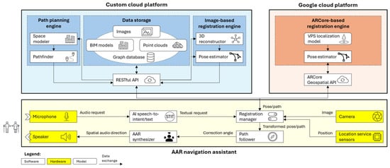
Figure 1.
System architecture of the proposed AAR navigation system including the custom cloud platform (light blue), the Google Cloud Platform (light orange), and the AAR navigation assistant (light yellow).
The proposed methodology is compatible with any portable device that has internet access and is equipped with basic hardware such as a camera, location service sensors, a microphone, and speakers. The camera captures visual information, condensed into images, which are used by CV engines for registration purposes. Location service sensors, including GNSS, Wi-Fi, Bluetooth, and cellular network data, help devices determine their raw location. The combination of multiple localization technologies makes the system more robust; as not all of them are always available, others can still contribute to an approximate location estimate. This is useful for verifying the availability of geolocated resources—such as nearby image dataset and 3D models—that can serve as reference during registration procedures. Finally, the microphone and speakers form the communication interface with BVIP. This paper focuses on a smartphone-based implementation of the system. The choice is made possible by the proposed system architecture (Figure 1), which delegates most of the computationally intensive tasks to cloud-based services. Consequently, the computational load and battery consumption are comparable to those of a smartphone collecting photos and delivering them to cloud-based services. The following subsections describe each component of the system architecture, providing an overview of the proposed methodology. The actual system implementation is detailed in Section 4.
3.1. Custom Cloud Platform Component
The custom cloud platform acts as a decentralized hub for data processing, storage, and distribution, utilizing a RESTful API as its core communication interface. This API enables seamless interaction with multiple navigation assistant clients over the internet. The custom platform supports two essential system functionalities: user pose tracking and reference path planning. These are facilitated by (i) the image-based registration engine, and (ii) the path planning engine, both supported by (iii) a data storage (Figure 1). The data storage component is responsible for hosting and managing geolocated resources applied by the two engines. These resources, including both unstructured data (e.g., images, point clouds) and structured data (e.g., BIM models), provide the necessary contextual information (Figure 1). A key feature of the platform is its ability to geolocate and align images, point clouds, and BIM models within a shared geospatial framework (WGS-84 standard), allowing precise mapping of virtual assets to real-world coordinates and supporting the integration of virtual and physical environments. Additionally, a graph database serves as the system’s backbone, ensuring robust data management. It enables efficient storage and powerful querying of interconnected heterogeneous data elements. Unstructured data are organized in a dedicated data lake and linked to structured information within the graph database to allow easy access and retrieval.
The image-based registration engine leverages CV algorithms to achieve accurate positioning in environments with limited access to the device location services, such as indoor areas or urban canyons, further addressing RQ.1. This engine applies SfM techniques and operates through two main phases supported by the 3D reconstructor and pose estimator modules (Figure 1). The 3D reconstructor, given a dataset of reference images, employs CNNs to extract feature points and generate a 3D model of the environment in the form of a point cloud. The pose estimator performs a 6-DoF localization of a single frame captured from the user’s current view (query image). Like the 3D reconstructor, it applies CNN-based feature extraction on the query image and matches these features against those from the 3D reconstruction. Notably, this approach does not require any preparatory infrastructure and relies solely on the acquisition of reference images. As such, it is suitable for deployment in unprepared environments, thereby addressing RQ.2.
The path planning engine consists of a headless simulation environment that can compute the shortest path connecting the user and the destination. To make this possible, two modules have been included: the space modeler and the pathfinder (Figure 1). The space modeler gets spatial information from georeferenced BIM models hosted by the data storage. The BIM model of the target environment can be queried based on the user position, which is continuously tracked based on a combination of device location services and CV technologies. Given the scenario made available by the space modeler, the pathfinder computes the reference path to the desired destination by applying a pathfinding algorithm. The A* algorithm, being one of the most popular in literature, has been assumed in this study as a reference for the implementation of the path planning engine. The possibility of retrieving the path to the desired destination in real-time enables the applicability of the system in unprepared environments. In fact, there is no need to predefine routes or install physical markers, answering RQ.2.
3.2. Google Cloud Platform Component
The ARCore-based registration engine, hosted on the Google Cloud Platform, complements the custom cloud platform by enhancing user tracking capabilities, particularly in outdoor environments where it improves upon device location services. Specifically, it refines the estimation of user poses beyond what device location services can offer, addressing RQ.1. For example, in dense urban areas, where tall structures obstruct the sky and signals reflect off surfaces, the accuracy of device location services often degrades. Another inherent limitation of device location services is their inability to determine device orientation [23]. Although the image-based registration engine could technically function outdoors, collecting large-scale reference image datasets presents significant challenges.
To overcome these limitations, the Google Cloud Platform offers a global localization service that operates without the need for prior environmental setup, thus contributing to RQ.2. By combining several advanced techniques, it enables accurate estimation of the smartphone camera pose. Communication between this engine and the rest of the system occurs through the ARCore Geospatial API (Figure 1). During a localization request, data from the device location services and a real-time image (query image) captured by the smartphone are transmitted to the Google Cloud Platform. Upon receiving the data, CV algorithms within the ARCore-based registration engine analyze the query image to detect and match distinct environmental features against Google’s extensive Street View image repository. This process is enabled by the VPS localization model. Ultimately, the CV algorithms determine both the 6-DoF position and orientation of the device.
3.3. AAR Navigation Assistant Component
The proposed assistant, as outlined earlier in this section, is implemented as a smartphone-based application. As shown in Figure 1, the assistant relies on a combination of hardware components (yellow boxes) and software modules (white boxes). Standard hardware found in commercially available smartphones—such as the camera, location service sensors (i.e., GNSS, Wi-Fi, Bluetooth, and cellular network data), microphone, speakers, and internet connectivity—is sufficient for system operation. The camera captures visual data for CV-based registration performed by the two cloud platforms, while device location sensors provide raw positioning to verify geolocated resources. The microphone and speakers enable communication with BVIP. On the software side, the assistant integrates four key modules: (i) an AI speech-to-intent/text converter, (ii) a registration manager, (iii) a path follower, and (iv) an AAR synthesizer. Once the assistant is launched, it starts listening to the user through the smartphone microphone. The AI speech-to-intent/text module oversees decoding the user speech and identifying the intent to navigate, and, if this is the case, converting the audio request for directions into a textual request. The latter is delivered to the registration manager.
To generate spatial guidance, user pose and reference path must be determined. The registration manager is responsible for retrieving this information, also by involving other components. The registration manager collects camera frames and raw location from the location service sensors of the smartphone. Based on this raw location, the manager continuously queries the custom cloud platform to retrieve any available image datasets or 3D reconstructed models located near the user position. The same module decides which cloud platform—custom or Google—will handle the pose estimation, relying either on the image-based registration engine (centimeter-level accuracy [29,30]) or the ARCore-based registration engine (meter-level accuracy [22]). The registration manager prioritizes the more accurate image-based system when available. In practice, if available, the custom platform is engaged to compute the user pose via the image-based engine. If no dataset is found nearby, the Google Cloud Platform and the ARCore-based engine take over. This further addresses RQ.1. The reference path must also be determined. To do so, the registration manager delivers the textual request, received from the AI speech-to-intent/text converter and including information about the destination, to the custom cloud platform. The latter returns the reference path computed by the path planning engine. At this point, the registration manager ensures both the user pose and the reference path are aligned within a consistent coordinate system. While the user’s position is continuously updated, the reference path is computed only when explicitly requested by the user.
The path follower module then utilizes the pose and path to calculate corrective angles that guide the user along the reference path toward the target destination. By adjusting the heading based on these corrections, the user progressively reduces both the distance to the path and the angular deviation from it [31]. To this end, an adapted form of the Line-Of-Sight (LOS) path following algorithm has been considered [31]. The geometric illustration of the LOS method adapted from [31] is reported in Figure 2. Given a path from the user current position to the set destination, discretized as a sequence of n points (i.e., from P1 to Pn), the path follower module logic can be described as a path-follower-controller procedure repeated for every discrete time k. In addition, the realistic situation in which the user may diverge from the reference path while navigation is considered. The path-follower-controller procedure computes the minimum distance, named the cross-tracking error , between the user current position and the reference path trajectory to find the reference point Pclose along the trajectory. Assuming Pnext as the successor of Pclose along the trajectory, the look-ahead distance Δh connecting Pclose and Pnext can be retrieved. The correction angle ψc, formed by the linear velocity vector v and the direction connecting the user position to Plos, can be computed as follows:
where as . It must be noted that, with respect to the z axis, ψlos is the angle formed by the direction connecting the user position to Plos, ψ is the angle formed by the linear velocity vector v, and ψp is the angle formed by the tangent line r, that is approximated by the straight line for two successive points Pclose and Pnext.
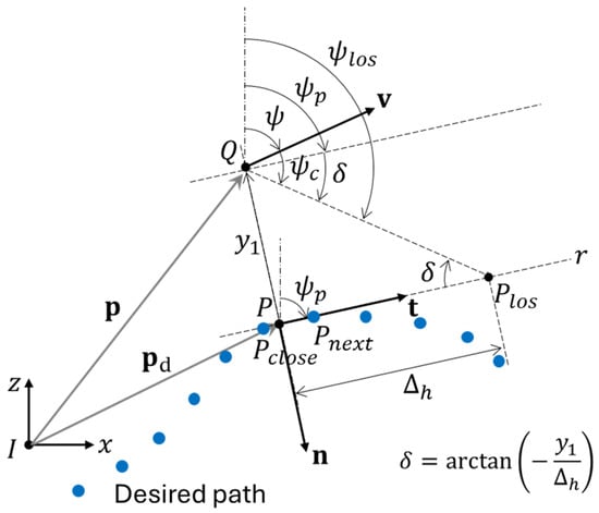
Figure 2.
Geometric illustration of the LOS method, adapted from [31], with blue dots representing the discretized path as a sequence of n points, from P1 to Pₙ.
Finally, the computed correction angle is passed to the AAR synthesizer, which delivers directional audio cues based on HRTFs. These cues follow an internal policy that links specific steering angles, falling within predefined ranges, to spatial audio directions (Table 1). This approach places virtual sound sources directly along the intended trajectory, ensuring that audio cues are consistently aligned with the user’s direction of travel, thereby reducing cognitive load and minimizing distractions from environmental noise.

Table 1.
Relationship between correction angle ranges and turn-by-turn directional audio cues.
4. System Implementation
In this section, the implementation of the system architecture is described with a focus on the key components directly developed by the authors. These are the main components hosted by the custom cloud platform and the AAR navigation assistant. Figure 3 depicts the information model that regulates their functioning and guides the system implementation. The Google Cloud Platform is not considered in this section since it is based on services made available by Google. For further details, please refer to the “GeospatialMode” method in the official documentation [32].
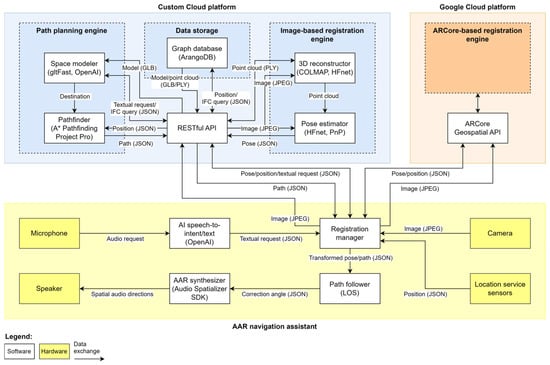
Figure 3.
Information model of the developed AAR navigation system including the custom cloud platform (light blue), the Google Cloud Platform (light orange), and the AAR navigation assistant (light yellow).
4.1. Custom Cloud Platform Implementation
The custom cloud platform has been implemented as a set of micro-services deployed using state-of-the-art containerization technologies, namely Docker [33]. At the core there is a backend web-service exposing a RESTful API that allows managing structured and unstructured data and running micro-services, such as the image based-registration engine and the path planning engine. The RESTful API has been implemented to enable communication between the custom cloud platform and its components (i.e., the image-based registration engine, the data storage, and the path planning engine) with the assistant, and the Google Cloud Platform. In addition, the backend web service stores permanent information using volumes provided by a Network-Attached Storage (NAS): while source files (e.g., images and BIM models) are stored in their original format, processed information (e.g., feature points and 3D point clouds) are stored using one database for each project.
The image-based registration engine has been developed as a micro-service including the 3D reconstructor and the pose estimator. The 3D reconstructor has been developed by implementing a SfM pipeline based on COLMAP [18] and Hierarchical Feature Network (HF-Net) [34] libraries (Figure 3). COLMAP, combined with learned local and global features provided by HF-Net, enables robust 3D reconstruction in the form of a sparse point cloud to be used as a reference during the following pose estimation. The pose estimator, instead, applies the same HF-Net combined with the Perspective-n-Point (PnP) algorithm [35] to retrieve the device’s pose by solving correspondence between 2D image points and 3D reconstruction points, enabling accurate camera localization within the pre-built 3D reconstruction.
The image-based registration engine performs user tracking supported by the data storage. It is assumed that 3D reconstructed models have been previously generated by the 3D reconstructor and stored within the data storage as PLY files. Each pose estimation call to the image-based registration engine provides a query image as a JPEG and location service sensors data as a JSON document (Figure 3). The location service sensors data are used to query the data storage for the closest 3D reconstructed model to the user (i.e., point cloud) to be used as a reference. Once identified, the 3D reconstructed model is delivered to the 3D reconstructor and made available to the pose estimator. The query image, which contains visual information, is processed by the pose estimator that returns the pose of the user as a JSON document.
The path planning engine, on the other hand, has been developed using the Unity3D game engine (version 2022.3) as a headless micro-service (Figure 3). When the assistant is launched, an executable Unity3D instance is initialized on a server. Unity3D has been selected because it embeds a physics engine that enables realistic path computation [36]. The path planning engine includes a space modeler and a pathfinder. The first one has been implemented using the gltFast library [37] that enables space modeling based on GLB models. GLB is the de facto standard for importing large scenes, like the ones related to BIM models, within Unity3D game engine. The second one, instead, implements the A* algorithm provided by the A* Pathfinding Project Pro library [38].
The path planning engine computes the reference path supported by the data storage. Path planning calls are triggered by the registration manager of the assistant. Each call to the path planning engine provides location service sensors data and the textual request for direction as a JSON document (Figure 3). Location service sensors data are used to query the data storage for the closest BIM model to the user to be used for path planning. Data storage is responsible not only for storing BIM models as IFC files, but also for extracting and returning the corresponding GLB files, which are more compact in size and therefore more portable on mobile devices. Hence, the selected BIM model is provided to the path planning engine. In particular, the space modeler oversees defining the spatial context according to the BIM models. Also, the textual request for directions is delivered to the space modeler to retrieve the destination. This is possible in two steps. First, the space modeler queries the data storage for the list of all IfcSpace entities with their associated names and GUIDs (globally unique identifiers) included in the selected BIM model. Second, the space modeler, implementing OpenAI-Unity library for Unity3D [39], enables the search of the destination’s GUID whose name matches the textual request for directions. At this point, the GUID of the identified IfcSpace can be used to retrieve the destination space. The geometric center corresponding to the filtered destination space is returned to the pathfinder. The latter, by using A*, can compute the shortest path connecting the user position and the destination and returns it to the registration manager of the assistant as a list of points in JSON format. During the navigation task, this will be used as the reference path by the path follower module included within the assistant.
4.2. AAR Navigation Assistant Implementation
The development of the proposed assistant requires a platform that supports Extended Reality (XR). The AAR navigation assistant has been developed in Unity3D (version 2022.3) and built as an Android application. Unity3D has been chosen for the first release to facilitate debugging and rapid development, taking advantage of its integrated spatial audio tools and efficient testing environment. Nevertheless, other platforms supporting XR development (e.g., Android Native XR) will be considered for future versions to achieve higher performance, reduced resource consumption, deeper system integration, and a more optimized, scalable application.
Once the application is launched, the assistant is initialized, and the microphone starts listening to the vocal request. The audio request is then delivered to the AI speech-to-intent/text module, developed using the speech-to-text and OpenAI libraries for Unity3D [39,40]. The vocal request is processed and, if a navigation intent is recognized, a textual request for directions is returned to the registration manager as a JSON document. Future studies will assess the performance of the AI speech-to-intent/text module. However, any potential latency due to the integration of OpenAI with Unity3D does not limit the system applicability. This is because the latency occurs only at the beginning of each vocal request for directions and does not affect navigation, as the module operates before navigation starts.
The registration manager, once it receives a textual request for directions, starts collecting images from the smartphone camera as JPEG files and location service sensor data as a JSON document. The latter is used to query the custom cloud platform and the Google Cloud Platform about the existence, in the vicinity of the user location, of any 3D reconstructed model based on custom image dataset or VPS model respectively. In the first case, collected data is delivered to the image-based registration engine, whereas in the second one to the ARCore-based registration engine. If both are available, the image-based registration engine has priority. At the same time the textual request is delivered to the custom cloud platform for path planning purposes. The registration manager receives from the custom cloud platform a JSON document including the user pose and the reference path. The manager checks for the consistency of received data with respect to the coordinate reference system of the assistant developed within Unity3D. The user pose, referring to a point cloud aligned with the BIM model, is expressed in the GLB coordinate reference system and must be converted into the Unity3D coordinate reference system. The reference path, on the other hand, originating from a Unity3D scene is already consistent with the assistant environment. Both the converted user pose and the reference path are delivered to the path follower module. This module has been developed in Unity3D by implementing using C# an adapted form of the LOS path following algorithm. Table 2 reports the pseudocode of the developed scripts and the related description. The “Main()” function initializes the path follower by loading the reference path, welcoming the user, and triggering the computation of the correction angle. The last action calls another function, namely “UpdateNavigationAssistant()”, that, once it verifies that the user is being tracked, starts and updates the computation of the correction angle. Also, this function informs the user about a successful or failed localization and, in the first case, provides directions. The last action calls another function, namely “GetDirections(correctionAngle)”, that provides the user with navigation directions, given the correction angle and after a frequency check is performed.

Table 2.
Pseudocode of the path follower module along with the related description.
The AAR synthesizer, once received the correction angle ψc, compares it with the angles ranges reported in Table 1 to identify the corresponding audio direction. For this study, HRTFs have been implemented in the AAR synthesizer using the Unity Audio Spatializer SDK [41]. This enables a spatial contextualization of turn-by-turn instructions with cues emitted by speakers so that they appear to come from the same direction of the followed trajectory.
5. Experiment and Result Discussions
5.1. Experiment Design
The developed assistant was tested on the university campus of Polo Monte Dago at Università Politecnica delle Marche in Ancona, Italy, which was used as a case study (Figure 4a). The Polo Monte Dago campus hosts the faculties of Engineering, Agriculture, and Sciences, distributed across several buildings comprising classrooms, offices, and laboratories. The main building, which houses the Faculty of Engineering, labels its floors according to their elevation above sea level: the lowest floor is called elevation 140 (140 m above sea level), while the highest floor, located at the top of the tower, is elevation 195. Each floor has a height of 5 m, with the faculty extending across eleven levels.
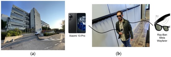
Figure 4.
(a) View of the university campus used as a case study, and (b) the experimental set up including the Xiaomi 13 Pro and the Ray-Ban Meta Glasses.
The overall experiment aims to test the effectiveness of the proposed navigation system in computing the reference path according to an audio request of the user (path planning tests) and guiding the user accessing the main building following turn-by-turn audio instructions (navigation tests). The experiments setup includes the smartphone Xiaomi 13 Pro and the Ray-Ban Meta Glasses (Figure 4b). The developed assistant built as an Android application has been installed on the selected smartphone. The Ray-Ban Meta Glasses with embedded speakers have been connected via Bluetooth with the smartphone for audio cues reproduction. The experiment design is based on the following assumptions:
- -
- The proposed system aligns with the category of EOAs, whose primary function is to support users in path planning and directional guidance, rather than obstacle avoidance or detection. This distinguishes it from ETAs, which are designed to assist users in safely exploring their surroundings by detecting obstacles.
- -
- The reference path is computed prior to the start of the navigation and the environment remains static throughout the traversal, with no new obstacles appearing during navigation.
- -
- The starting point is the same for all the path planning tests, since the user launches the assistant in the same position outdoors.
- -
- The destination point, on the other hand, corresponding to the geometric center of the classroom assumed as a destination, varies according to it. As a result, the shortest path connecting the user and the destinations is returned and applied as reference paths by the assistant to provide turn-by-turn audio instructions to the user during navigation tasks.
- -
- The existence of at least a path connecting the starting and the destination points is a prerequisite for the execution of both the path planning and the navigation tests. Hence, the existence of no paths is considered as a failure of the system.
Given these assumptions, the following sequence of tasks defines the procedure for executing the tests:
- Reach the defined starting point.
- Launch the developed navigation assistant application by a manual tap or vocally using the Google assistant (e.g., “Hey Google, open the AAR navigation assistant”).
- Provide an audio request for path planning (e.g., “Please, provide the directions to reach (name of the room)”).
- Frame the surroundings area with the smartphone camera.
- Start the navigation following turn-by-turn audio instructions provided by the assistant until reaching the destination. The application collects user positions during navigation and measures time elapsed to reach the destination.
The first part of the experiment consists in executing path planning tests. The effectiveness of the proposed navigation system in computing the reference path according to an audio request of the user was evaluated. To this purpose, task no. 1–4 have been executed for the following classrooms at elevation 140 selected as destinations: “Classroom 140/1”, “Classroom 140/2”, “Classroom 140/3”, “Classroom 140/D3”, and “Classroom 140/4”. Results of these tests have been reported and discussed in Section 5.3.1.
The second part of the experiment consists of executing navigation tests. The effectiveness of the proposed system in guiding the user accessing the main building following turn-by-turn audio instructions was evaluated. To this purpose, tasks no. 1–5 have been executed with respect to just one destination, namely “Classroom 140/3”. Tests have been executed by 20 users (10 male and 10 female) ranged in age from 24 to 64 including undergraduate, graduate, and PhD students, researchers, and professors. Owing to their academic roles, all participants were familiar with the testing environment. Each user performed the test twice, both times using the proposed AAR navigation system: first under blindfolded conditions, and then under sighted conditions to provide a benchmark. The blindfolded condition has been considered to assess system performance and identify potential shortcomings before extending its applicability to BVIP. The sighted condition, on the other hand, has been considered to provide a baseline. Results of these tests have been reported and discussed in Section 5.3.2.
5.2. Evaluation Metrics
To assess the effectiveness of the proposed assistant, this study aims to measure its performance by quantifying how a user, under its guidance, diverges from a reference path. Computing trajectory similarity is a fundamental operation in movement analytics, required for search, clustering, and classification of trajectories [42]. Among a broad range of applications, a plethora of methods for measuring trajectory similarity has emerged. Three key characteristics are especially useful in classifying these similarity measures: their metric properties, trajectory granularity, and spatial and temporal reference frames [42]. Literature reports the most important and commonly used similarity measures: Dynamic Time Warping (DTW), Edit Distance on Real sequences (EDR), Longest Common Subsequence (LCSS), Discrete Fréchet Distance (DFD), and Continuous Fréchet Distance (CFD) [42]. For this study, the Fréchet Distance in its continuous variant (i.e., CFD) is preferred over the others. It has been selected to compute the maximum distance between two trajectories. First, it is a metric that ensures high flexibility, as it evaluates spatial similarity while ignoring time shifts. Since this study considers human trajectories recorded at different times and speeds, flexibility is a key requirement. Furthermore, the continuous variant (i.e., CFD) is preferable to the discrete one (i.e., DFD) because the latter only aligns the measured locations, which can lead to issues with non-uniform sampling. In contrast, CFD considers continuous alignments between all points in both trajectories by interpolating them. In this study, CFD has been computed using the Curvesimilarities Python library (version v0.4.0a4) [43].
To carry out a detailed and informative analysis beyond the maximum divergence provided by the CFD, it is useful to also consider average and local deviations. For this purpose, the CFD has been complemented with the Average Continuous Fréchet Distance (ACFD)—already established in the literature [42]—which measures the mean deviation between two trajectories. ACFD was computed as the arithmetic mean of the minimum perpendicular distances from each point on the user trajectory to the closest line segment of the reference trajectory. This metric provides a robust quantification of the mean lateral deviation between the user and reference paths over their entire spatial extent.
Finally, by applying the CFD to moving windows along the two trajectories, it becomes possible to estimate local deviations between them. In this study, and for consistency with the previously introduced metrics, this localized measure is referred to as the Local Continuous Fréchet Distance (LCFD). Specifically, within each window, the LCFD is computed as the minimum perpendicular distance from each point on the user trajectory to the nearest line segment of the reference trajectory.
To gain deeper insight into the behavior of the LCFD, potential relationships between LCFD values and the local curvature of the user trajectory were investigated. Curvature, in this context, provides a measure of how sharply the path changes direction, which may influence deviations from the reference trajectory. Rather than employing the classical geometric definition of curvature based on the radius of the osculating circle—typically computed from the unique circumcircle passing through three consecutive points—curvature has been estimated using a discrete, time-aware formulation tailored to sampled trajectory data with possibly irregular temporal resolution [44]. This choice is motivated by the need for robustness and computational efficiency in the presence of noisy or discretely sampled motion data, where classical differential estimators may become unstable or ill-defined. Specifically, for each triplet of consecutive trajectory points, the angle between the two adjacent displacement vectors was calculated, capturing the instantaneous turning behavior of the trajectory at that location. To incorporate the temporal dimension and reflect how quickly the direction changes, the angular difference between consecutive triplets was divided by the corresponding time interval. This yields a measure of the temporal rate of change of direction, which serves as a practical proxy for local curvature dynamics in the trajectory.
Providing the aforementioned metrics to measure the effectiveness of the developed navigation system, a methodology to answer RQ.3 is established.
5.3. Result Discussion
In this section, the results of both experiments are reported and discussed. In particular, the results of the path planning tests are presented in Section 5.3.1, whereas the results of the navigation tests are presented in Section 5.3.2.
5.3.1. Path Planning Tests
This section discusses the results of the path planning tests, aimed at assessing the effectiveness of the proposed navigation system in computing the reference path. A summary of the path planning tests towards the five destinations is reported in Table 3, and Figure 5 depicts the shortest path connecting the starting point and the destination “Classroom 140/3”, assumed as the reference path during navigation tests (Section 5.3.2). The remaining reference paths to destinations “Classroom 140/1”, “Classroom 140/2”, “Classroom 140/D3”, and “Classroom 140/4” have been reported in Figure A1 (Appendix A.1). The five classrooms can be accessed through more than one door, highlighted in orange for each classroom (Figure 5 and Figure A1). It must be noted that, for each pathfinding task, the computed path crosses the door that ensures the shortest path. In the path planning tests no. 1 and 2, the computed reference paths cross a classroom (Figure A1a,b). This may represent a limitation in case the classroom cannot be crossed (e.g., is locked or occupied). Future studies will try to overcome this limitation by leveraging BIM semantics to prioritize routes along dedicated pathways. Overall, a path planning engine exploiting standard building representations provided by BIM models avoids the need to carry out preliminary surveys to manually define available paths, preparing the environment and wearing heavy technological configurations to scan the environment and process collected data during navigation tasks. Technical solutions adopted in this study make it possible by integrating such a path planning engine with the assistant for BVIP. In addition, since reference paths can be computed according to the building topology in real-time, any BIM model update can be considered by the path planning engine with minimal effort. This is enabled by the choice of modelling the space within a Unity3D headless instance based on BIM models. This answers RQ.2. Real-time pathfinding is achieved by delegating the computation to a path planning engine embedded within the custom cloud platform, rather than running this computation locally within the smartphone-based assistant. The custom cloud platform processes the request and returns a simple list of vectors. The efficiency of such a technical solution is confirmed by computing times for the five path planning tests in the order of tens of milliseconds (Table 3). The performance will be even higher on field applications, since the graphic rendering, required for the experimental and debug purposes of the study, will be disabled. This answers RQ.3.

Table 3.
Result overview for the path planning tests.
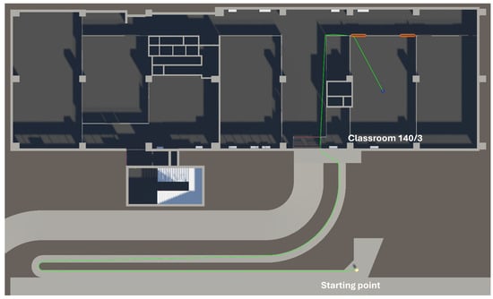
Figure 5.
Example of reference path to destination “Classroom 140/3” obtained during the path planning test no. 1.
5.3.2. Navigation Tests
Results of the navigation tests, aimed at assessing the effectiveness of the proposed navigation system in guiding users to access the main building by following turn-by-turn audio instructions, are reported and discussed in this section.
Table 4 and Table 5 provide an overview of navigation test results conducted in blindfolded and sighted conditions, respectively, with the latter serving as a benchmark. CFD and ACFD, both computed by comparing the user trajectory with the reference path, as well as the user trajectory length and the duration of the navigation are reported. Figure 6a and Figure 7a refer to navigation test no. 1 in blindfolded and sighted conditions, respectively, and show a comparison between the clockwise user trajectory (blue line with dots) and the reference trajectory to destination “Classroom 140/3” (dashed orange line). The point on the user trajectory where the CFD is registered is indicated (red dot). The indoor–outdoor boundary, indicating the transition point between indoor and outdoor areas, is also reported (black X). The remaining trajectory comparison charts for navigation tests no. 2–20 in blindfolded and sighted conditions are presented in Figure A2 and Figure A3, respectively, (Appendix A.2). On one hand, a qualitative comparison of the trajectories in the outdoor area (above the black X) and in the indoor area (below the black X) shows that the user’s trajectory does not exhibit noticeable patterns or discontinuities near the boundary point (black X). This indicates that the behavior of the navigation assistant remains stable and consistent across both indoor and outdoor environments. On the other hand, a qualitative comparison of the trajectories in both blindfolded and sighted conditions, compared with each other and with the reference path, does not reveal any significant differences or patterns that can be directly attributed to one condition or the other. In addition, a quantitative comparison of navigation performance between blindfolded and sighted conditions was conducted using the Wilcoxon Signed-Rank test (Table 6). The resulting p-values for CFD, ACFD, user path length, and duration were 14.29%, 16.50%, 20.24%, and 12.31%, respectively. In all cases, the p-values exceed the commonly adopted significance threshold of 5%, indicating that no statistically significant differences were observed between the two conditions across the evaluated metrics. These results suggest that blindfolded users, supported by the proposed navigation assistant, achieved performance comparable to sighted users, highlighting the effectiveness of the developed system. Figure 6b and Figure 7b, referring to navigation test no. 1 in blindfolded and sighted conditions, respectively, present trajectory analysis based on the curvature of the user trajectory (blue line with dots), the CFD (red point), the ACFD (dotted green line), the LCFD (green line with crosses), and the shoulder width threshold (dashed green line). The remaining trajectory analysis charts for navigation tests no. 2–20 in blindfolded and sighted conditions are reported in Figure A4 and Figure A5 (Appendix A.3). Generally, an increase in curvature is associated with a corresponding increase in LCFD. This pattern is also observable across all the tests, suggesting a general trend that applies to both sighted and blindfolded navigation conditions. Therefore, users in blindfolded conditions do not exhibit poorer performance compared to sighted users. This behavior can thus be considered independent of the presence or absence of visual feedback. It can be explained by the difficulty, sometimes encountered by users, in decoding the difference between qualitative audio directions such as “turn slightly left/right” versus “turn left/right”. Future studies will focus on providing audio cues that better represent correction angles. Figure 8 and Figure 9 present data from navigation tests in blindfolded and sighted conditions, respectively, the results of a descriptive statistical analysis in the form of extended boxplots including the Interquartile Range (IQR) (light blue boxplot with grey line), whiskers (black line), median (blue line), mean (red triangle), 95% confidence intervals (red dashed line), standard deviation (red dotted line), and the distribution of values (green dots) of (a) CFD, (b) ACFD, (c) user path length, and (d) duration. Overall, the proximity between mean and median values suggests that the distribution of the values is approximately symmetric, with no strong skewness or outlier influence (Figure 8 and Figure 9). This reinforces the representativeness of the mean as a central descriptor and supports the reliability of the reported statistical summary. Additionally, the relatively narrow boxplots suggest that the IQR encompasses data points with limited variability, indicating that most observations are clustered closely around the median. Additionally, the relatively small values of both the standard deviation and the confidence interval further support the conclusion that the dataset exhibits low overall variability. This also implies that the estimate of the mean is both precise and reliable, reinforcing the robustness of the observed central tendency. In blindfolded conditions, mean CFD values over 20 tests were equal to 1.46 m, with mean ACFD equal to 0.43 m (Figure 8a,b). This finding indicates that, except for sporadic deviations averaging 1.46 m, blindfolded users typically deviate from the reference path by approximately 0.43 m on average, a value that remains well within the shoulder width threshold of 0.60 m. In sighted conditions, the values are higher, suggesting that sighted users tend to navigate more independently and approximate the reference trajectory more loosely. As a consequence, while in blindfolded conditions (Table 4) the ACFD values consistently remained below the shoulder width threshold in 100% of the tests; in sighted conditions (Table 5) the threshold is met in 15 out of 20 tests (75%), indicating greater variability in user adherence to the reference path. Specifically, the mean CFD and ACFD are 1.57 m and 0.52 m, respectively, which are approximately 0.10 m higher than the corresponding values observed under blindfolded conditions (Figure 9a,b). This observation is further supported by the notably shorter navigation times recorded under sighted conditions compared to blindfolded ones, despite the path being of comparable length. These results indicate that blindfolded users, who must devote greater cognitive effort to interpret AAR messages, tend to move more slowly than sighted users when covering the same distance. Indeed, in blindfolded conditions, a mean user path length of 125.99 m is covered in an average duration of 164.55 s (Figure 8c,d). Conversely, under sighted conditions, a very similar mean path length of 125.51 m is completed in just 151.30 s on average—over 10 s less (Figure 9c,d). This further highlights the impact of the additional cognitive load required to interpret AAR messages on navigation speed in blindfolded users. Nevertheless, and most importantly, this condition ultimately results in lower average CFD and ACFD values compared to the sighted condition. Therefore, despite a slower navigation pace, users under blindfolded conditions exhibit greater conformity to the reference path compared to those navigating under sighted conditions. The results obtained demonstrate that the effectiveness of the developed assistant remains consistent across different tests and users. Specifically, given a reference path, multiple users followed the turn-by-turn audio instructions provided by the proposed system with comparable levels of divergence, path length, and navigation duration. This answers RQ.3.

Table 4.
Result overview of the navigation tests in blindfolded conditions.

Table 5.
Result overview of the navigation tests in sighted conditions.

Figure 6.
Error analysis of navigation test no. 1 in blindfolded conditions. (a) Comparison between the user trajectory (blue line with dots) and the reference trajectory to destination “Classroom 140/3” (dashed orange line). The CFD point (red dot) and the indoor–outdoor boundary (black X) are also indicated. (b) Trajectory analysis based on the curvature of the user trajectory (blue line with dots), highlighting the CFD (red dot), the ACFD (dotted green line), the LCFD (green line with crosses), and the shoulder width threshold (dashed green line).

Figure 7.
Error analysis of navigation test no. 1 in sighted conditions. (a) Comparison between the user trajectory (blue line with dots) and the reference trajectory to destination “Classroom 140/3” (dashed orange line). The CFD point (red dot) and the indoor–outdoor boundary (black X) are also indicated. (b) Trajectory analysis based on the curvature of the user trajectory (blue line with dots), highlighting the CFD (red dot), the ACFD (dotted green line), the LCFD (green line with crosses), and the shoulder width threshold (dashed green line).

Table 6.
Comparison of navigation test results using the Wilcoxon Signed-Rank test.

Figure 8.
Statistical analysis of navigation tests in blindfolded conditions: extended boxplots including the IQR, whiskers, median, mean, 95% confidence intervals, standard deviation, and the distribution of values for (a) CFD, (b) ACFD, (c) user path length, and (d) duration.

Figure 9.
Statistical analysis of navigation tests in sighted conditions: extended boxplots including the IQR, whiskers, median, mean, 95% confidence intervals, standard deviation, and the distribution of values for (a) CFD, (b) ACFD, (c) user path length, and (d) duration.
6. Conclusions
The evolution of navigation tools for BVIP reflects a transition from traditional mechanical aids (e.g., white canes) to sophisticated electronic systems that leverage sensing, processing, and feedback technologies to improve mobility and orientation. Addressing this gap—and the research questions outlined in Section 1—this paper introduces a novel AAR navigation system for BVIP, expanding on work presented at the 24th International Conference on Construction Applications of Virtual Reality (CONVR 2024). AAR technology is used to provide spatial audio guidance, seamlessly overlaying auditory cues within the user’s real-world 3D environment to support intuitive navigation for BVIP. This positions the proposed system not as a replacement, but as a complementary tool to traditional mobility aids such as white canes and guide dogs. While these conventional solutions provide localized obstacle detection and immediate tactile or behavioral feedback, the proposed system enhances spatial awareness and extends navigational capabilities by delivering high-level guidance toward both familiar and unfamiliar destinations. To this end, the proposed AAR navigation system—which falls into the EOAs category—integrates BIM and CV technologies, with the aid of device location services, to support key functionalities: user pose tracking, reference path planning, and direction communication. Specifically, CV technologies are utilized to develop two complementary registration engines—the image-based and ARCore-based engines—that together enable seamless user tracking across both indoor and outdoor environments. This integration has the potential to significantly enhance BVIP independence by eliminating the need for prior environmental preparation, such as installing infrastructure or markers, which has traditionally been a barrier to adoption. Notably, this preparation-free approach extends beyond user tracking to include BIM-based path planning. In fact, the path planning engine leverages semantic data embedded within BIM models, allowing for real-time generation of navigation paths without requiring activities such as environmental scanning or predefined route mapping. A basic BIM model is sufficient for this purpose, as the system does not rely on highly detailed geometric modeling to perform path planning. Any updates to BIM models are automatically detected and incorporated by the path planning engine to provide updated paths. The availability of Google VPS data and BIM models no longer constitutes a limiting factor in terms of environmental preparation. On the contrary, the growing digitalization of the AEC sector and the built environment—through platforms such as Google VPS and the increasing availability of BIM models for both existing and new structures—further enhance the applicability and scalability of the system.
A limitation of the system lies in areas where neither custom image datasets nor Street View images are available, resulting in reduced localization accuracy. However, this limitation is expected to diminish as global digitization progresses. Another limitation concerns the reliability of employed CV technologies during light transitions. Although they remain functional in low-light conditions, a drop in localization performance may occur. Nevertheless, this is compensated by increasingly high-performing cameras available on the market at affordable prices. Finally, as the proposed solution falls within the category of Electronic Orientation Aids (EOAs), its primary function is to support navigation by determining a path and delivering directional cues. As such, it does not address obstacle detection, a functionality typically associated with Electronic Travel Aids (ETAs). Therefore, to ensure comprehensive and safe navigation in real-world contexts, the system would benefit from integration with obstacle detection technologies or complementary use alongside traditional mobility aids—such as a white cane or guide dog—thereby enhancing its overall applicability and safety for BVIP.
In future studies, the path planning engine will be enhanced by leveraging BIM semantics to prioritize routes along dedicated indoor (e.g., hallways) and outdoor (e.g., sidewalks) communication pathways, while avoiding unnecessary traversal through spaces like rooms or roadways. In addition, the AAR assistant will be assessed and enhanced across various facets and modules. First, potential latency related to the AI speech-to-intent/text module, although it does not affect navigation as it runs prior to the process, will be assessed in future studies. Second, the path follower module and the AAR synthesizer will be improved to provide audio cues that better represent correction angles, thereby helping users distinguish between qualitative audio directions. This would ensure a limited divergence of navigation trajectories along curved sections. Third, future studies will focus on optimizing the implementation of the AAR navigation assistant by analyzing computing times and battery consumption. In line with this, other platforms supporting XR development (e.g., Android Native XR) will be considered for future versions to achieve higher performance, reduced resource consumption, deeper system integration, and a more optimized and scalable application. Also, future studies will involve an expanded experimental campaign encompassing a wider range of navigation scenarios, with particular attention to indoor–outdoor transitions, to further assess the assistant’s robustness and continuity across environmental changes. The possibility of making the system available to BVIP will be explored in future studies to gather user feedback, support system scalability and generalizability in real-world environments, and define appropriate fallback mechanisms. Finally, future studies will also address data ethics considerations, particularly regarding the collection, processing, and storage of visual and spatial data, to ensure compliance with ethical standards and user privacy regulations.
Author Contributions
Conceptualization, L.M. and M.V.; methodology, L.M. and M.V.; software, L.M. and M.V.; validation, L.M., M.V. and L.B.; formal analysis, L.M. and M.V.; investigation, L.M. and M.V.; resources, L.M. and M.V.; data curation, L.M., M.V. and L.B.; writing—original draft preparation, L.M.; writing—review and editing, L.M., M.V., A.C. (Alessandra Corneli), A.C. (Alessandro Carbonari) and L.B.; visualization, L.M. and M.V.; supervision, A.C. (Alessandra Corneli) and A.C. (Alessandro Carbonari); project administration, A.C. (Alessandra Corneli); funding acquisition, A.C. (Alessandra Corneli) and A.C. (Alessandro Carbonari). All authors have read and agreed to the published version of the manuscript.
Funding
This research has received funding from the project Vitality—Project Code ECS00000041, CUP I33C22001330007—funded under the National Recovery and Resilience Plan (NRRP), Mission 4 Component 2 Investment 1.5—‘Creation and strengthening of innovation ecosystems,’ construction of ‘territorial leaders in R&D’—Innovation Ecosystems—Project ‘Innovation, digitalization and sustainability for the diffused economy in Central Italy—VITALITY’ Call for tender No. 3277 of 30/12/2021, and Concession Decree No. 0001057.23-06-2022 of Italian Ministry of University funded by the European Union—NextGenerationEU.
Institutional Review Board Statement
The study was conducted in accordance with the Declaration of Helsinki, and approved by the Research Ethics Committee (Comitato Etico per la Ricerca) of Università Politecnica delle Marche (UNIVPM) (protocol code: 0197787, approval date: 8 September 2025).
Informed Consent Statement
Informed consent was obtained from all subjects involved in the study.
Data Availability Statement
The raw data supporting the conclusions of this paper will be made available by the authors on request.
Acknowledgments
This paper is an extended version of our previous work entitled “Audio Augmented Reality Seamless Navigation Assistant Based on GNSS and Computer Vision for Blind and Visually Impaired People”, which was presented at the 24th International Conference on Construction Applications of Virtual Reality (CONVR 2024), in Sydney, Australia. The authors acknowledge the support and feedback from the chairs and co-chairs of CONVR 2024.
Conflicts of Interest
The authors declare no conflicts of interest. The funders had no role in the design of the study, in the collection, analyses, or interpretation of data, in the writing of the manuscript, or in the decision to publish the results.
Appendix A
Appendix A.1
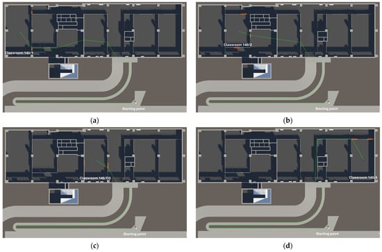
Figure A1.
Summary of the reference paths to destinations (a) “Classroom 140/1”, (b) “Classroom 140/2”, (c) “Classroom 140/D3”, and (d) “Classroom 140/4”, obtained during the path planning tests no 2–5.
Appendix A.2
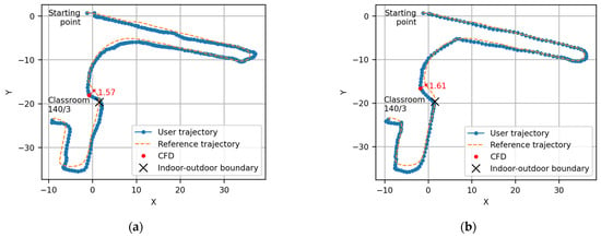
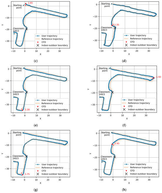
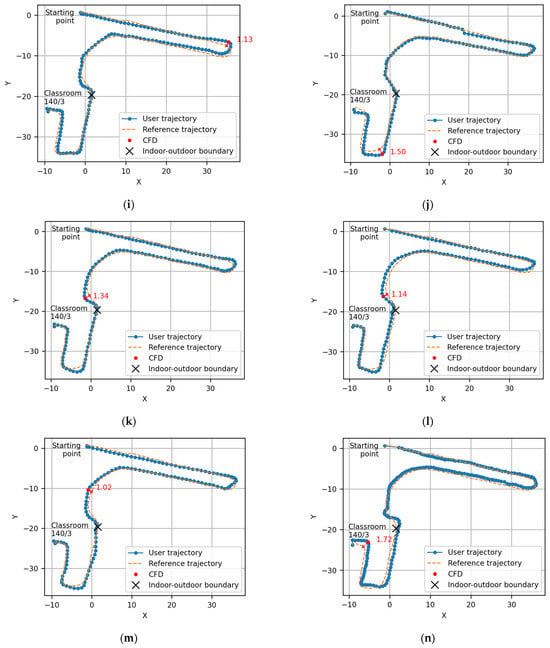
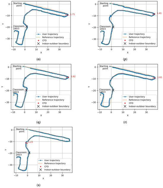
Figure A2.
(a–s) Summary of the results for navigation tests no. 2–20 in blindfolded conditions: comparison between the user trajectory (blue line with dots) and the reference trajectory to destination “Classroom 140/3” (dashed orange line). The CFD point (red dot) and the indoor–outdoor boundary highlighted (black X) are also indicated.
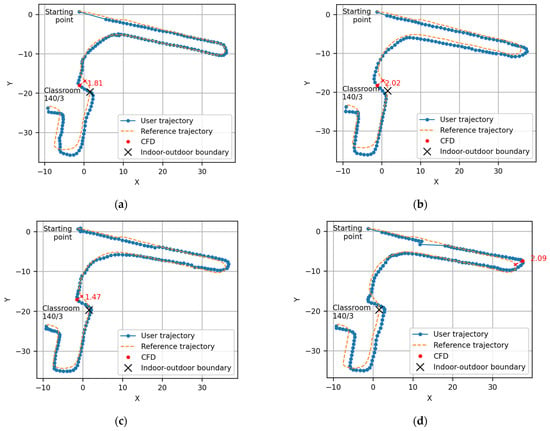
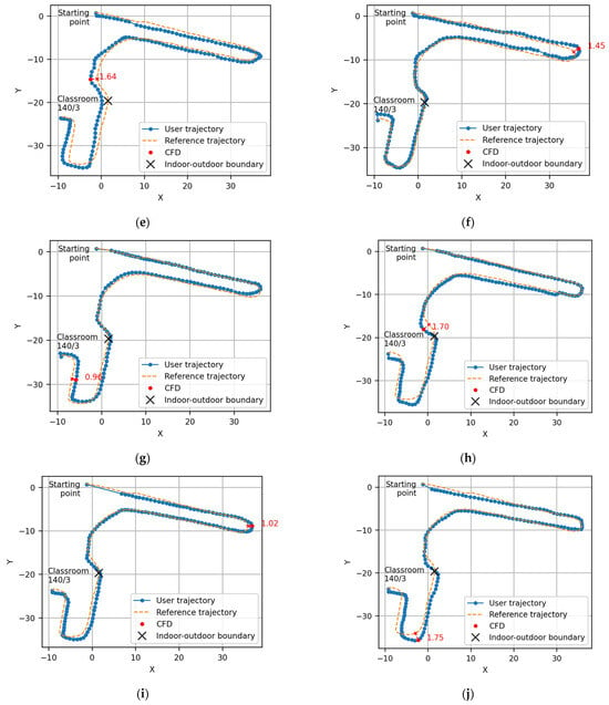
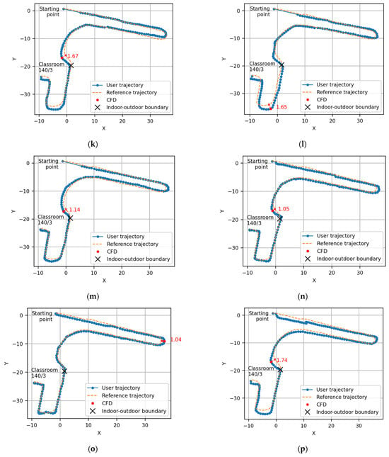
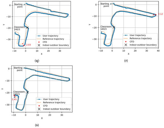
Figure A3.
(a–s) Summary of the results for navigation tests no. 2–20 in sighted conditions: comparison between the user trajectory (blue line with dots) and the reference trajectory to destination “Classroom 140/3” (dashed orange line). The CFD point (red dot) and the indoor–outdoor boundary remarked (black X) are also indicated.
Appendix A.3
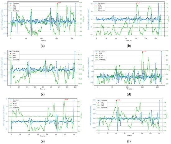
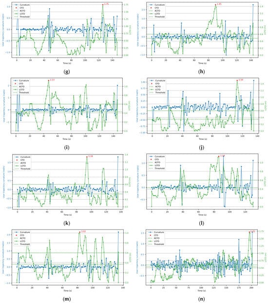
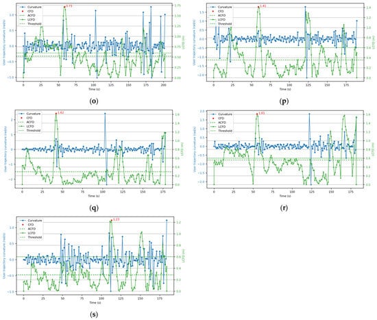
Figure A4.
(a–s) Summary of the results for navigation tests no. 2–20 in blindfolded conditions: trajectory analysis based on the curvature of the user trajectory (blue line with dots), the CFD (red dot), the ACFD (dotted green line), the LCFD (green line with crosses), and the shoulder width threshold (dashed green line).

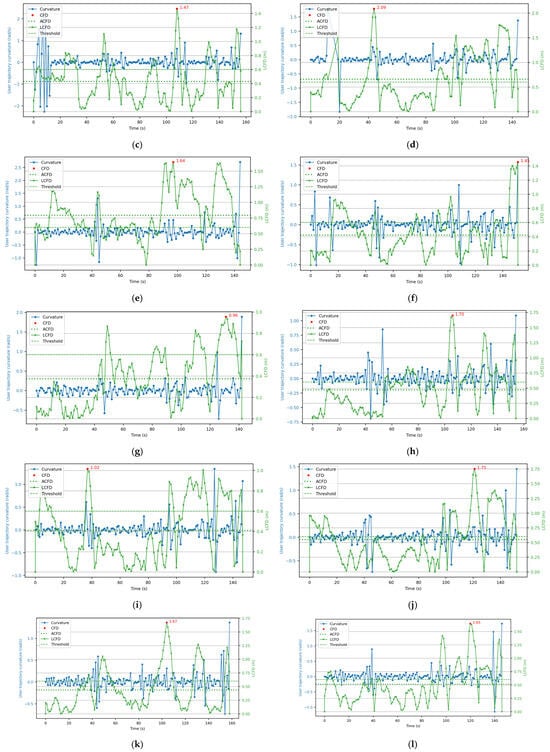
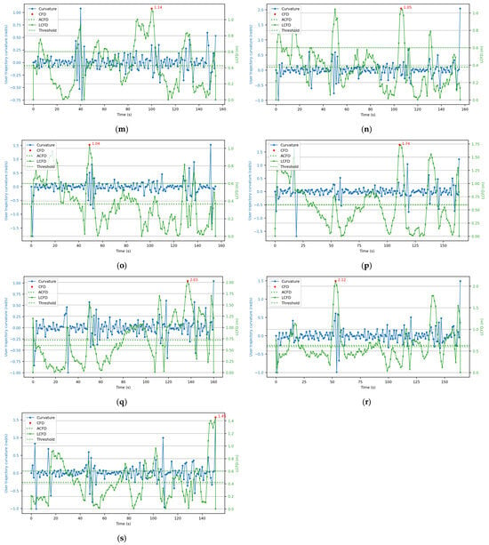
Figure A5.
(a–s) Summary of the results for navigation tests no. 2–20 in sighted conditions: trajectory analysis based on the curvature of the user trajectory (blue line with dots), the CFD (red dot), the ACFD (dotted green line), the LCFD (green line with crosses), and the shoulder width threshold (dashed green line).
References
- Zafar, S.; Asif, M.; Bin Ahmad, M.; Ghazal, T.M.; Faiz, T.; Ahmad, M.; Khan, M.A. Assistive Devices Analysis for Visually Impaired Persons: A Review on Taxonomy. IEEE Access 2022, 10, 13354–13366. [Google Scholar] [CrossRef]
- Messaoudi, M.D.; Menelas, B.A.J.; Mcheick, H. Review of Navigation Assistive Tools and Technologies for the Visually Impaired. Sensors 2022, 22, 7888. [Google Scholar] [CrossRef] [PubMed]
- Kuriakose, B.; Shrestha, R.; Sandnes, F.E. Tools and Technologies for Blind and Visually Impaired Navigation Support: A Review. IETE Tech. Rev. 2022, 39, 3–18. [Google Scholar] [CrossRef]
- García-Pereira, I.; Casanova-Salas, P.; Gimeno, J.; Morillo, P.; Reiners, D. Cross-Device Augmented Reality Annotations Method for Asynchronous Collaboration in Unprepared Environments. Information 2021, 12, 519. [Google Scholar] [CrossRef]
- Abidi, M.H.; Noor Siddiquee, A.; Alkhalefah, H.; Srivastava, V. A Comprehensive Review of Navigation Systems for Visually Impaired Individuals. Heliyon 2024, 10, e31825. [Google Scholar] [CrossRef] [PubMed]
- Kim, I.J. Recent Advancements in Indoor Electronic Travel Aids for the Blind or Visually Impaired: A Comprehensive Review of Technologies and Implementations. Univers. Access Inf. Soc. 2024, 24, 173–193. [Google Scholar] [CrossRef]
- Fernando, N.; McMeekin, D.A.; Murray, I. Route Planning Methods in Indoor Navigation Tools for Vision Impaired Persons: A Systematic Review. Disabil. Rehabil. Assist. Technol. 2023, 18, 763–782. [Google Scholar] [CrossRef] [PubMed]
- Lim, K.Y.; Ho, Y.L. NFC Label Tagging Smartphone Application for the Blind and Visually Impaired in IoT. In Information Science and Applications, Lecture Notes in Electrical Engineering; Kim, H., Kim, K.J., Park, S., Eds.; Springer: Singapore, 2021; pp. 305–315. [Google Scholar]
- Bendanillo, B.J.B.; Orteza, V.J.P.; Palad, J.P.B.; Samonte, M.J.C. Sight-Man: A Smart Infrared Technology That Guides the Visually Impaired. In ACM International Conference Proceeding Series; Association for Computing Machinery: New York, NY, USA, 2020; pp. 61–65. [Google Scholar]
- Yamashita, A.; Sato, K.; Matsubayashi, K. Pedestrian Navigation System for Visually Impaired People Using HoloLens and RFID. In Proceedings of the 2017 Conference on Technologies and Applications of Artificial Intelligence (TAAI), Taipei, Taiwan, 1–3 December 2017. [Google Scholar]
- Martinez-Sala, A.S.; Losilla, F.; Sánchez-Aarnoutse, J.C.; García-Haro, J. Design, Implementation and Evaluation of an Indoor Navigation System for Visually Impaired People. Sensors 2015, 15, 32168–32187. [Google Scholar] [CrossRef] [PubMed]
- Narupiyakul, L.; Sanghlao, S.; Yimwadsana, B. An Indoor Navigation System for the Visually Impaired Based on RSS Lateration and RF Fingerprint. In Smart Homes and Health Telematics, Designing a Better Future: Urban Assisted Living; Springer International Publishing AG: Cham, Switzerland, 2018. [Google Scholar]
- Ahmetovic, D.; Gleason, C.; Ruan, C.; Kitani, K.; Takagi, H.; Asakawa, C. NavCog: A Navigational Cognitive Assistant for the Blind. In Proceedings of the 18th International Conference on Human-Computer Interaction with Mobile Devices and Services, Florence, Italy, 6–9 October 2016; Association for Computing Machinery, Inc.: New York, NY, USA, 2016; pp. 90–99. [Google Scholar]
- Chaccour, K.; Badr, G. Novel Indoor Navigation System for Visually Impaired and Blind People. In Proceedings of the 2015 International Conference on Applied Research in Computer Science and Engineering (ICAR), Beiriut, Lebanon, 8–9 October 2015. [Google Scholar]
- Bai, J.; Lian, S.; Liu, Z.; Wang, K.; Liu, D. Virtual-Blind-Road Following-Based Wearable Navigation Device for Blind People. IEEE Trans. Consum. Electron. 2018, 64, 136–143. [Google Scholar] [CrossRef]
- Croce, D.; Giarré, L.; Pascucci, F.; Tinnirello, I.; Galioto, G.E.; Garlisi, D.; Lo Valvo, A. An Indoor and Outdoor Navigation System for Visually Impaired People. IEEE Access 2019, 7, 170406–170418. [Google Scholar] [CrossRef]
- Jonas, S.M.; Sirazitdinova, E.; Lensen, J.; Kochanov, D.; Mayzek, H.; De Heus, T.; Houben, R.; Slijp, H.; Deserno, T.M. IMAGO: Image-Guided Navigation for Visually Impaired People. J. Ambient. Intell. Smart Environ. 2015, 7, 679–692. [Google Scholar] [CrossRef]
- Schönberger, J.L.; Frahm, J.-M. Structure-from-Motion Revisited. In Proceedings of the 2016 IEEE Conference on Computer Vision and Pattern Recognition (CVPR), Las Vegas, NV, USA, 27–30 June 2016. [Google Scholar]
- Sarlin, P.-E.; DeTone, D.; Malisiewicz, T.; Rabinovich, A. SuperGlue: Learning Feature Matching with Graph Neural Networks. arXiv 2019, arXiv:1911.11763. [Google Scholar]
- Lindenberger, P.; Sarlin, P.-E.; Pollefeys, M. LightGlue: Local Feature Matching at Light Speed. In Proceedings of the 2023 IEEE/CVF International Conference on Computer Vision (ICCV), Paris, France, 1–6 October 2023. [Google Scholar]
- Zhang, X.; Yao, X.; Zhu, Y.; Hu, F. An ARCore Based User Centric Assistive Navigation System for Visually Impaired People. Appl. Sci. 2019, 9, 989. [Google Scholar] [CrossRef]
- Google for Developers Build Global-Scale, Immersive, Location-Based AR Experiences with the ARCore Geospatial API. Available online: https://developers.google.com/ar/develop/geospatial (accessed on 31 July 2024).
- Reinhardt, T. Using Global Localization to Improve Navigation. Available online: https://research.google/blog/using-global-localization-to-improve-navigation/ (accessed on 31 July 2024).
- Bai, J.; Su, G.; Liu, D.; Fu, Z. A Cloud and Vision-Based Navigation System Used for Blind People. In ACM International Conference Proceeding Series; Association for Computing Machinery: New York, NY, USA, 2017; Volume Part F128531. [Google Scholar]
- Lee, Y.H.; Medioni, G. RGB-D Camera Based Wearable Navigation System for the Visually Impaired. Comput. Vis. Image Underst. 2016, 149, 3–20. [Google Scholar] [CrossRef]
- ISO 16739-1:2024; Industry Foundation Classes (IFC) for Data Sharing in the Construction and Facility Management Industries. International Organization for Standardization: Geneva, Switzerland, 2024.
- Vaccarini, M.; Spegni, F.; Giretti, A.; Pirani, M.; Carbonari, A. Interoperable Mixed Reality for Facility Management: A Cyber-Physical Perspective. J. Inf. Technol. Constr. 2023, 29, 573–595. [Google Scholar] [CrossRef]
- Yang, J.; Barde, A.; Billinghurst, M. Audio Augmented Reality: A Systematic Review of Technologies, Applications, and Future Research Directions. AES J. Audio Eng. Soc. 2022, 70, 788–809. [Google Scholar] [CrossRef]
- Messi, L.; Corneli, A.; Spegni, F.; Binni, L.; Vaccarini, M. Infrastructure-Free Localization System for Augmented Reality Registration in Indoor Environments: A First Accuracy Assessment. In Proceedings of the 2024 IEEE International Workshop on Metrology for Living Environment, Chania, Greece, 12–14 June 2024. [Google Scholar]
- Messi, L.; Spegni, F.; Vaccarini, M.; Corneli, A.; Binni, L. Seamless Augmented Reality Registration Supporting Facility Management Operations in Unprepared Environments. J. Inf. Technol. Constr. 2024, 29, 1156–1180. [Google Scholar] [CrossRef]
- Hung, N.; Rego, F.; Quintas, J.; Cruz, J.; Jacinto, M.; Souto, D.; Potes, A.; Sebastiao, L.; Pascoal, A. A Review of Path Following Control Strategies for Autonomous Robotic Vehicles: Theory, Simulations, and Experiments. J. Field Robot. 2023, 40, 747–779. [Google Scholar] [CrossRef]
- Google for Developers ARCore API Reference. Available online: https://developers.google.com/ar/reference (accessed on 31 July 2024).
- Docker Inc. Docker. Available online: https://www.docker.com/ (accessed on 12 August 2024).
- Sarlin, P.-E.; Cadena, C.; Siegwart, R.; Dymczyk, M. From Coarse to Fine: Robust Hierarchical Localization at Large Scale. In Proceedings of the 2019 IEEE/CVF Conference on Computer Vision and Pattern Recognition (CVPR), Long Beach, CA, USA, 15–20 June 2019. [Google Scholar]
- OpenCV. Perspective-n-Point (PnP) Pose Computation. Available online: https://docs.opencv.org/4.x/d5/d1f/calib3d_solvePnP.html (accessed on 22 December 2023).
- Naticchia, B.; Messi, L.; Carbonari, A. BIM-Based Holonic System for Real-Time Pathfinding in Building Emergency Scenario. In Proceedings of the 2019 European Conference for Computing in Construction, Chania, Greece, 10–12 July 2019; Volume 1, pp. 117–124. [Google Scholar]
- Unity Technologies. Unity GlTFast Documentation. Available online: https://docs.unity3d.com/Packages/com.unity.cloud.gltfast@6.10/manual/index.html (accessed on 24 January 2025).
- Granberg, A. A * Pathfinding Project Pro. Available online: https://arongranberg.com/astar/docs/ (accessed on 27 November 2021).
- Altundas, S. OpenAI-Unity. Available online: https://github.com/srcnalt/OpenAI-Unity (accessed on 11 March 2025).
- Unity Technologies. Speech-to-Text API. Available online: https://www.assemblyai.com/products/speech-to-text (accessed on 24 March 2025).
- Unity Technologies. Audio Spatializer SDK. Available online: https://docs.unity3d.com/Manual/AudioSpatializerSDK.html (accessed on 30 July 2024).
- Tao, Y.; Both, A.; Silveira, R.I.; Buchin, K.; Sijben, S.; Purves, R.S.; Laube, P.; Peng, D.; Toohey, K.; Duckham, M. A Comparative Analysis of Trajectory Similarity Measures. GIscience Remote Sens. 2021, 58, 643–669. [Google Scholar] [CrossRef]
- Curvesimilarities Curvesimilarities. Available online: https://github.com/JSS95/curvesimilarities (accessed on 2 August 2024).
- Tapp, K. Differential Geometry of Curves and Surfaces; Springer: Berlin/Heidelberg, Germany, 2016. [Google Scholar]
Disclaimer/Publisher’s Note: The statements, opinions and data contained in all publications are solely those of the individual author(s) and contributor(s) and not of MDPI and/or the editor(s). MDPI and/or the editor(s) disclaim responsibility for any injury to people or property resulting from any ideas, methods, instructions or products referred to in the content. |
© 2025 by the authors. Licensee MDPI, Basel, Switzerland. This article is an open access article distributed under the terms and conditions of the Creative Commons Attribution (CC BY) license (https://creativecommons.org/licenses/by/4.0/).