1. Introduction
Accidental loads such as explosions, fire, and impact can cause local damage to structural components, potentially triggering progressive collapse and leading to severe consequences [
1,
2]. As a result, investigating the progressive collapse behavior of structures is essential [
3,
4]. Engineering experience indicates that structural fires are often accompanied by subsequent impact loads. For instance, in 2001, the Twin Towers of the World Trade Center collapsed after being struck by hijacked passenger aircraft, resulting in significant casualties. Subsequent investigations identified the extensive fires caused by the impact as the primary factor contributing to the collapse [
5].
In recent years, the impact resistance of steel structures at room temperature has been extensively studied. Initial research focused on the influence of impact energy and related parameters on individual components, such as steel beams [
6,
7,
8,
9]. Findings indicate that increased impact energy prolongs impact duration and residual deformation but has limited effect on the peak impact force and the shape of the time history curve. Subsequent studies have examined the dynamic response of steel frame beam–column structures under impact loading. Results highlight that joint configuration significantly influences structural performance under impact, with reinforced connections improving both load-bearing capacity and ductility [
10,
11]. Notably, enlarged through-weld-hole joints enhance rotational resistance under impact [
12]. In addition, Wang et al. [
13,
14] integrated previous findings and, through numerical simulations and experiments, systematically investigated the effects of joint type, impact location, and mass. Their results show that flange plate connections exhibit the weakest impact resistance among various joint types [
15], and that impact location strongly affects the structural response [
16].
While research on the impact response of steel structures at room temperature is relatively mature, studies under fire conditions remain in the developmental stage. Existing work has primarily focused on static fire tests, which can be categorized into three main areas. At the member level, studies on the fire resistance of individual components such as beams [
17,
18] and columns [
19] have demonstrated that high temperatures significantly reduce both stiffness and load-bearing capacity. At the connection level, beam–column joints—recognized as structural weak points—have been extensively examined. For example, Fan et al. [
20] found that the load ratio is a dominant factor in joint fire resistance, and that thickened concrete slabs enhance performance; their ABAQUS model also accurately predicted full-process joint behavior under fire [
21]. Dai et al. [
22,
23] showed that large-size columns reduce beam displacement but introduce strong axial restraints, increasing the risk of joint fracture. Guo et al. [
24] demonstrated that WUF-B joints exhibit high ductility and large deformation capacity due to compression failure after lower flange fracture, with a transition from arching degradation to catenary action as temperature increases [
25]. Jiang et al. [
26] reported that columns with strong restraints tend toward quasi-static failure, while those with weak restraint or high load ratios are prone to dynamic failure. At the structural level, full-scale natural fire tests on portal steel frames [
27,
28] successfully captured real fire-induced temperature distributions and collapse modes. However, it is important to note that these studies are limited to static conditions. In real engineering scenarios, fire is often accompanied by secondary hazards such as explosion or impact. Thus, there is an urgent need to investigate the coupled effects of fire and impact loads. Meanwhile, recent studies have emphasized the crucial role of fire effects in structural performance evaluation [
29,
30,
31].
In summary, research on steel frame beam–column structures has primarily focused on impact tests at room temperature and static fire tests. While some studies have explored the coupling effects of fire and impact on steel frames, numerous challenges remain unresolved. Building on the impact tests conducted by Wang et al. [
15], this paper employs finite element analysis to investigate the dynamic impact behavior of steel frame beam–column structures under fire conditions. The study begins by simulating and validating the impact test at room temperature, followed by the verification of the temperature field and the sequential thermal–mechanical coupling model. Finally, an extended parametric analysis is conducted for the validated room-temperature impact test, considering factors such as fire temperature, fire area, and impact momentum. The findings provide valuable insights for disaster prevention and mitigation in steel structures within practical engineering applications.
2. Room Temperature FE Modeling and Verification
2.1. Introduction to the Experiment
Wang et al. [
15] investigated the impact resistance of plane steel frame structures through falling-floor impact tests. In this study, the Welded Unreinforced Flange-Bolted Web (WUF-B) connection from [
15] is adopted for simulation analysis. Due to site constraints and the inability to install out-of-plane restraints, a 1/2-scale specimen was used. The specimen span is 3160 mm, and the steel column height is 1000 mm. All beams and columns are standard I-sections as specified in BS 4-1 [
32], with the beam section UB 203 × 133 × 30 and the column section UC 203 × 203 × 71. To mitigate potential large torsional and out-of-plane deformations, stiffeners and additional steel plates were welded at the beam mid-span. Lateral constraints were provided by A-shaped steel frames on both sides, simulating the restraint from undamaged surrounding structural elements. The column was connected to the A-frame through horizontal load cell.
2.2. FE Model Setup and Validation
The welded unreinforced flange-bolted web connection (WUF-B) substructure model was validated through ABAQUS-based numerical simulation. A refined finite element model (
Figure 1) simulates the full process of the steel frame span resisting falling weight impact. The finite element model was established using 8-node linear brick elements with reduced integration and hourglass control (C3D8R), each node possessing three translational degrees of freedom. Critical interfaces—including beam–column welded regions—were constrained using Tie commands, while all contact interactions implemented hard-contact normal behavior. Boundary conditions replicated the experimental configuration: the column bases were fixed, the beam ends were restrained against vertical displacement, while the lateral restraint provided by the auxiliary A-frame in the test was simulated using nonlinear spring elements, which realistically captured the horizontal flexibility of the support system.
The strain rate effect under high speed motion is considered according to the Cowper–Symonds [
33] intrinsic model as shown in Equation (1):
where
is the yield strength of steel at strain rate
and
is the yield strength of steel. Assuming that the strain rate effect does not change with strain hardening, the values of
and
are set to 6844 s
−1 and 3.9, respectively.
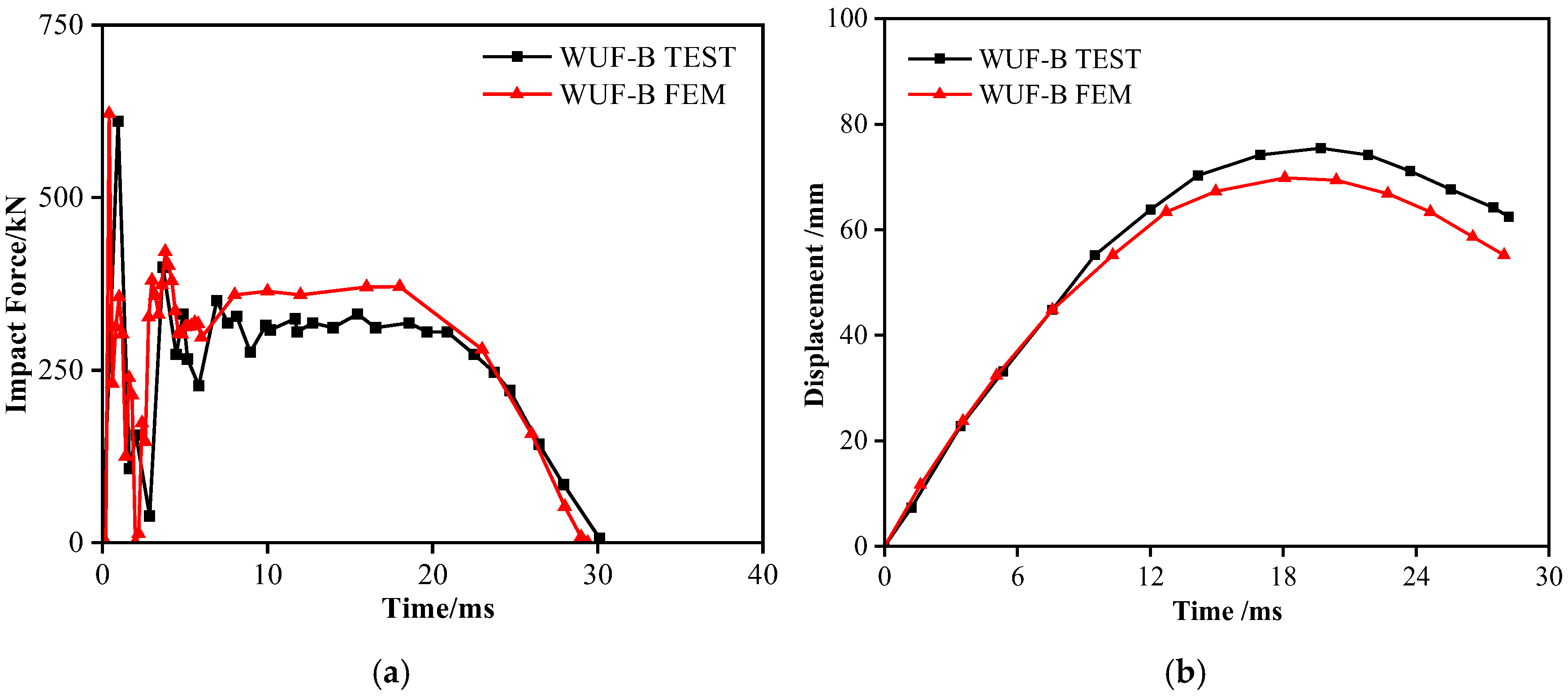
Figure 2 compares experimental and simulated impact response metrics: simulation yields 70.3 mm span displacement, 621.5 kN peak impact force, and 29.7 ms impact duration, while test measurements show 75.4 mm, 607.0 kN, and 30.7 ms, respectively, minimal relative errors of 6.8%, 2.4%, and 3.3%. The high curve agreement and marginal force/displacement deviations validate model accuracy. This is further substantiated by damage mode in
Figure 3, where localized flange buckling at beam–column welds in WUF-B specimens (test) is precisely replicated in simulations. The finite element model thus exhibits exceptional capability in predicting lower-flange buckling behavior and replicating ambient-temperature impact responses of steel frame substructures.
3. FE Modeling and Verification Under Fire
3.1. Temperature Field Validation
To validate the accuracy of our temperature field simulations for structural steel members, we modeled the 4-span, 2-story planar steel frame test specimen from [
34] using solid (C3D8RT) elements with temperature degrees of freedom. Thermal loading was applied to the bottom center column following the ISO834 standard [
35] fire curve, whose expression is:
where
is the temperature at moment t and
is the initial temperature.
The applied fire boundary conditions (radiation and convection) were established based on Eurocode 1, Part 1-2 [
36], which provides design provisions for thermal loading scenarios. The structural steel adopted in this study was Q235B, whose material parameters were calibrated against the above Eurocode recommendations to ensure consistency with standardized fire design practice.
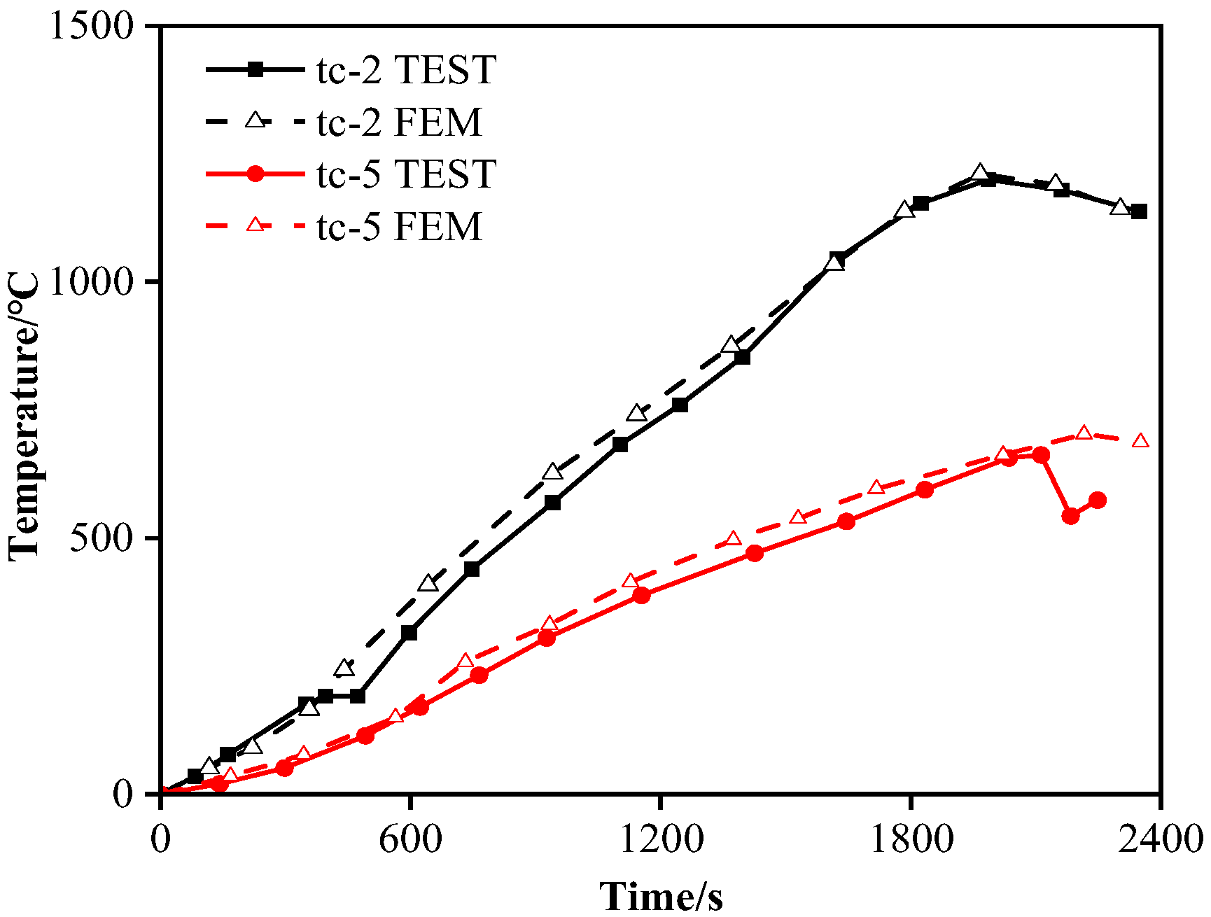
Figure 4 shows the comparison of temperature rise time history curves and finite element results of tc-2 and tc-5 at different test points. Both curves exhibit highly consistent temperature-rise trends and peak values, confirming the method’s effectiveness in simulating high-temperature thermal behavior of steel structural components.
3.2. Coupled Thermo-Mechanical Model Verification
To validate the sequential thermo-structural coupling methodology, we simulated high-temperature impact tests on restrained portal frame beams [
25]. The experimental setup positioned beams within a heating furnace, applying uniform ISO-834 standard heating via combined radiation and convection boundary conditions. Internal temperature distributions were governed by thermal conduction, monitored by surface thermocouples. Upon reaching target temperatures, prompt furnace-side removal enabled immediate impact testing.
Employing the impact-resistant welded connection (WC) as the validation benchmark, this study examines a portal frame with 0.9 m column height and 1.6 m beam span. Specimens utilize Q235B-grade I-sections subjected to 137 kg hammer impact from 7.2 m height at a measured beam-surface temperature of 400 °C.
Figure 5 demonstrates consistent failure modes between simulation and experiment, with mid-span displacements of 158 mm (simulated) versus 166 mm (tested), showing an approximate 5% discrepancy. This close agreement validates the thermo-mechanical coupling model’s reliability in predicting structural response under combined fire and impact loading.
The high-temperature verification in this study was based on portal-frame beam tests reported in the literature, rather than on WUF-B joints. This choice was driven by the scarcity of experimental data on WUF-B connections under combined fire and impact conditions. The intent of this verification is not to reproduce joint-specific details, but to confirm that the thermal–mechanical coupling in the FE model—namely thermal softening, stiffness degradation, and dynamic response—follows experimentally observed trends under standardized heating. The ambient-temperature validation in
Section 2.2 ensures that connection-specific impact mechanics of WUF-B are accurately captured, while the high-temperature benchmark establishes confidence in the model’s ability to reproduce degradation pathways at elevated temperatures.
4. Impact Behavior of WUF-B Steel Frame Under Fire
4.1. Modeling Under Fire
To investigate the impact resistance of steel frames with welded unreinforced flange-bolted web (WUF-B) connection under fire, this section uses the sequential thermal mechanical coupling method to establish the impact model under fire. The same element formulation was adopted consistently in both the thermal and the sequential thermo-mechanical coupling analyses to ensure compatibility.
In the coupled thermo-mechanical analysis, temperature-dependent mechanical properties (elastic modulus and yield strength) were defined according to Eurocode 3, Part 1-1 [
37], and thermal properties (conductivity, specific heat, and expansion) followed Eurocode 3, Part 1-2 [
36,
38]. The transient temperature field, obtained from a heat-transfer analysis using the ISO-834 curve, was imported into the structural model as a time-dependent predefined field, ensuring that stiffness degradation and thermal expansion effects were consistently captured during impact simulations. The fire model is shown in
Figure 6.
4.2. Discussion on Strain-Rate Effect Under Fire Conditions
At ambient temperature, structural steel exhibits pronounced strain-rate sensitivity, with dynamic strengthening leading to increases in yield and ultimate strength under impact. However, this effect diminishes significantly at elevated temperatures. Beyond 600 °C, thermal softening governs the material response, and the relative contribution of strain-rate enhancement becomes marginal, typically below 5%. As a result, under combined fire–impact scenarios, the global response is dominated by stiffness degradation, large displacements, and catenary action rather than material strain-rate strengthening. Therefore, this paper takes the strain rate parameter calibrated under environmental conditions as a reasonable approximation, because it may slightly overestimate the dynamic strengthening effect, while the overall structural response (displacement and axial force development) is mainly controlled by temperature, making the results insensitive to the change in strain rate parameters.
4.3. Impact Force and Mid-Span Displacement
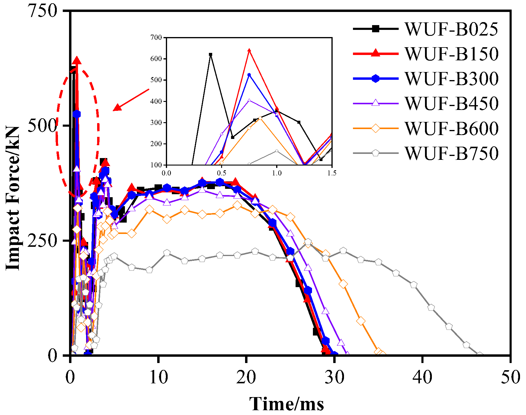
Figure 7 shows the impact force time history curve at different temperatures. Under identical impact conditions, impact force characteristics exhibit minimal variation below 450 °C. At 600 °C, the curve changes significantly: peak impact force decreases rapidly, steady-state impact force declines substantially, and total impact duration increases markedly. At the same time, with the increase in temperature, the peak impact force corresponding to the components at 25 °C, 150 °C, 300 °C, 450 °C, 600 °C and 750 °C are 621.5, 639.9, 525.1, 404.8, 320.5 and 166.2 kN, respectively. Relative to room temperature, peak force reductions are 15.5% (300 °C), 34.9% (450 °C), 48.4% (600 °C), and 73.3% (750 °C). At 150 °C, the deterioration of steel is not obvious due to low temperature, but due to the effect of thermal expansion, the member stiffness is slightly larger than that of the room temperature specimen, so the peak impact force increases by 2.9%.
Above 600 °C, peak impact force falls below steady-state impact force. The reason is that the elastic modulus of steel decreases sharply at high temperature, the local stiffness of the structure near the impact point also decreases rapidly, the contact time of impact is significantly extended, and the rising speed of force becomes slow. Therefore, the peak force is significantly reduced and “passivated”. The steady-state impact force represents the stabilized force level after initial impact deformation, governing global structural deformation. This force is mainly used to push the overall large deformation of the structure. It is mainly determined by the work capacity of the impact kinetic energy conversion (energy dissipation rate), and is related to the overall residual strength and deformation capacity of the structure at high temperature. Although the stable impact force is also far lower than the room temperature level due to the softening of steel at high temperature, the degree of decline is not as large as the first peak impact force at high temperature.
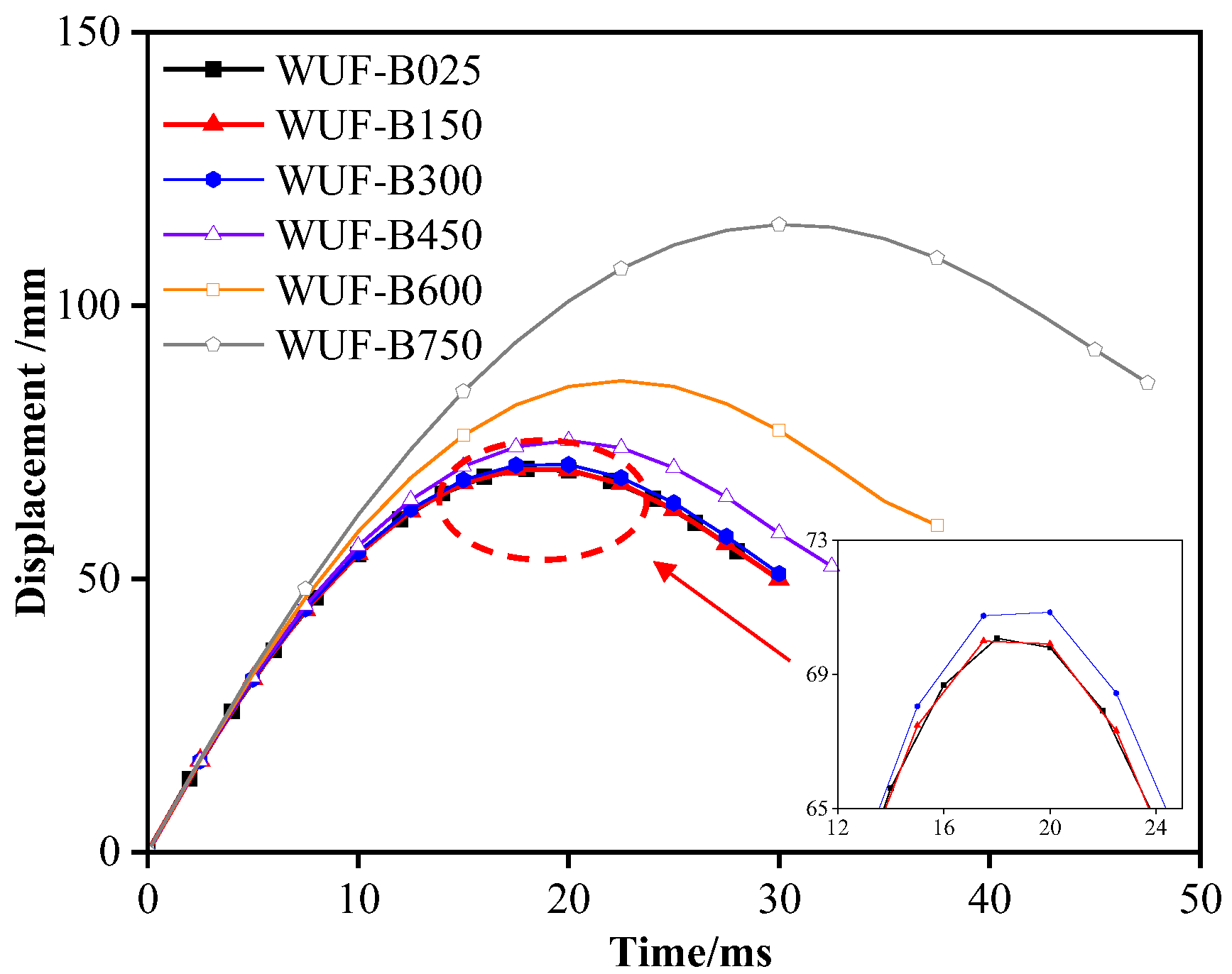
Figure 8 presents mid-span displacement time history curves. Displacements at 25 °C, 150 °C, 300 °C, 450 °C, 600 °C, and 750 °C are 70.3 mm, 70.1 mm, 70.9 mm, 75.3 mm, 86.3 mm, and 114.8 mm, respectively. Relative to room temperature, displacements increase by 0.9% (300 °C), 7.1% (450 °C), 22.8% (600 °C), and 63.3% (750 °C). This is due to the fact that as temperature rises, material properties degrade more quickly, reducing the components’ energy absorption capacity. As a result, longer durations and greater deformations are needed to dissipate the impact energy. At 150 °C, thermal expansion slightly increases the specimen’s stiffness compared to ambient temperature, while mid-span displacement is marginally reduced under impact load.
4.4. Axial Force and Support Reaction Force
As shown in
Figure 9, up to 300 °C, the maximum axial force on the member slightly decreases with increasing temperature. This is due to the axial pressure from thermal expansion, which counterbalances the axial tension generated during localized impact. However, above 450 °C, a sharp increase in the axial force is observed, linked to the degradation of steel properties. This leads to a significant reduction in the steel frame’s stiffness. The softening of the steel reduces the bending capacity, requiring greater deformation to absorb the impact energy, the catenary mechanism in the fire affected area plays a greater role. As shown in
Figure 10, the effect of catenary force was calculated by axial force and rotation angle. After the temperature reached 600 °C, the effect of catenary increased exponentially. As a result, the peak axial force rises, and the time to reach it is prolonged.
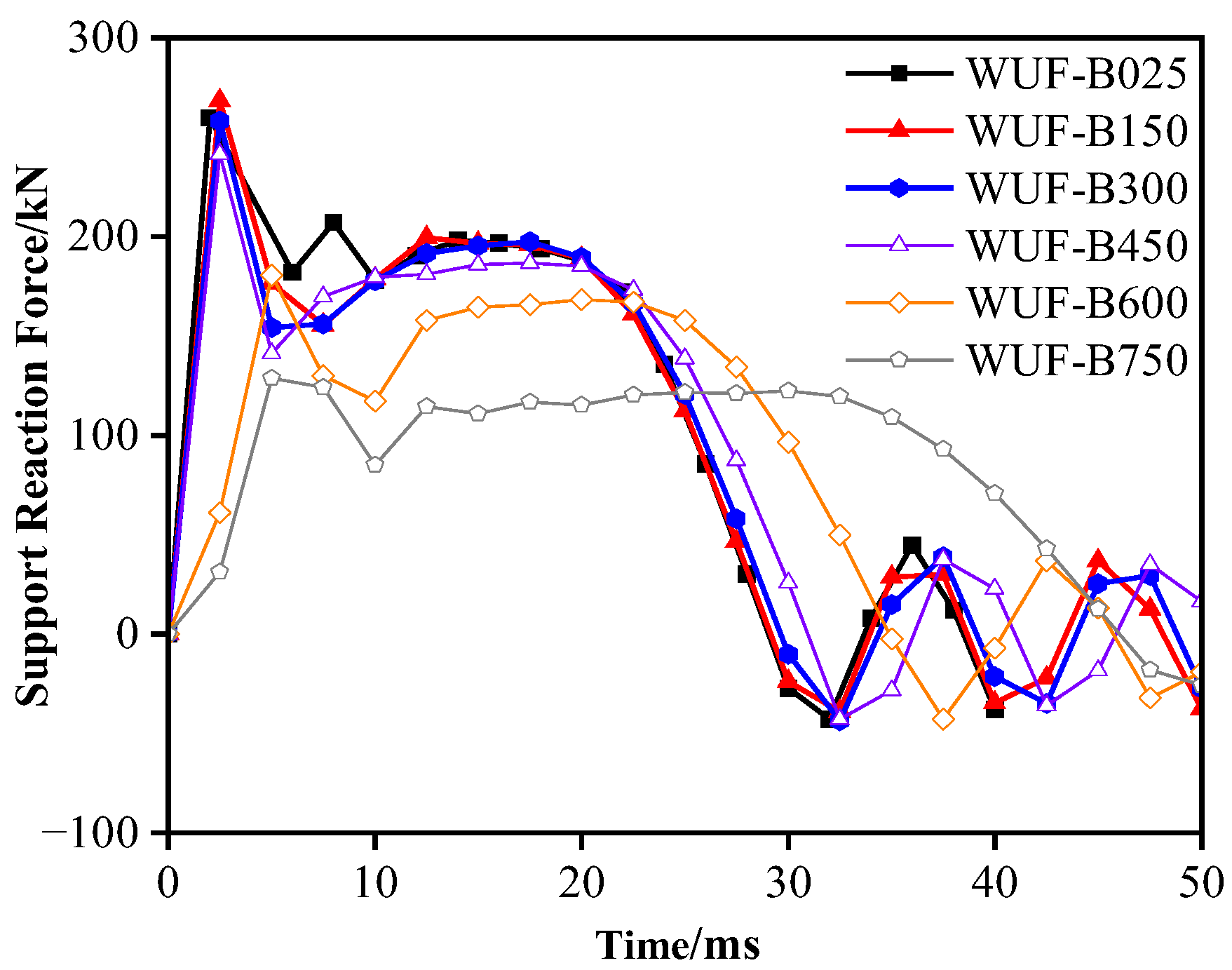
Figure 11 shows the time history curve of the support reaction for different components. The curve features an initial peak force, followed by a decrease and eventual stabilization. This behavior is due to the rapid transmission of the impact force from the hammer’s initial contact with the steel beam to the support via the beam–column structure. As the impact concludes, the hammer rebounds, causing the support reaction to decrease. Once the hammer fully detaches, the support reaction stabilizes, with periodic vibrations around 0 kN.
4.5. Energy Dissipation Analysis
Wang et al. [
15] suggest that the energy
absorbed by the component’s overall deformation under impact can be estimated by integrating the impact force-displacement curve, i.e., calculating the area enclosed between the axes. As shown in
Figure 12, the
values for the component at 25 °C, 150 °C, 300 °C, 450 °C, 600 °C, and 750 °C are 18.8, 18.5, 18.2, 18.3, 18.5, and 18.0 kJ, respectively. The total kinetic energy of the falling hammer,
, is expressed as:
where
is the mass of the falling hammer,
is the initial velocity at the impact of the falling hammer, and
is calculated to be 24.6 kJ. The energy absorption rate of the overall deformation of the component can be obtained from
.
Table 1 shows
,
, and
for different components. At the initial stage of temperature rise, the energy absorption rate of the component’s overall deformation decreases. This is due to thermal expansion, which slightly increases structural stiffness, reducing deformation at the mid-span of the beam–column connection. As temperature rises further, the steel’s stiffness and strength decrease, leading to greater deformation in the fire-affected area, and the component absorbs more energy, increasing the energy absorption rate. However, at 750 °C, the impact force drops sharply due to significant fire-induced degradation. Although energy is absorbed through increased mid-span deformation, the efficiency is low, causing a continued decrease in the absorption rate.
4.6. Strain Distribution Analysis
Figure 13 shows the distribution of the maximum equivalent plastic strain in the member at different temperatures. Between 150 °C and 450 °C, plastic deformation is mainly concentrated in the impact contact area and near the beam–column joint. The lower flange at the connection between the upper flange and the beam–column in the mid-span area exhibits significant local buckling, while the lower mid-span flange and the upper flange at the joint are in tension. Above 600 °C, the plastic strain distribution changes drastically due to the fire’s effect on the member’s underside. High plastic deformation occurs in the fire-affected zone at the middle and lower parts of the steel frame span, and flange deformation at the joint intensifies. This shift is primarily due to the degradation of material properties at high temperatures: beyond 600 °C, the stiffness of the lower flange decreases sharply, causing rapid large deformations under impact. When deformation reaches a certain point, a catenary mechanism forms to resist the impact load.
5. Numerical Analysis
5.1. Different Fire-Exposed Areas
ISO-834 was selected to provide a reproducible thermal boundary for comparative studies. Localized or asymmetric heating scenarios—such as single-sided lower-flange exposure—may further reduce local stiffness, prolong contact duration, and increase mid-span displacement, potentially leading to earlier local failure.
Given the significant variability of fire events in real-world conditions, it is crucial to systematically study the impact of different fire scenarios on the dynamic response of components. Since upper-layer fires can lead to the collapse of the upper structure and subsequent impact from falling layers, this section compares three typical fire conditions: single-sided fire on the upper flange of the steel beam (A1), single-sided fire on the lower flange (A2), and three-sided fire (A3), which is commonly studied in traditional research, as shown in
Figure 13. Due to the severe performance degradation of steel above 600 °C, the critical temperature was selected for impact simulation.
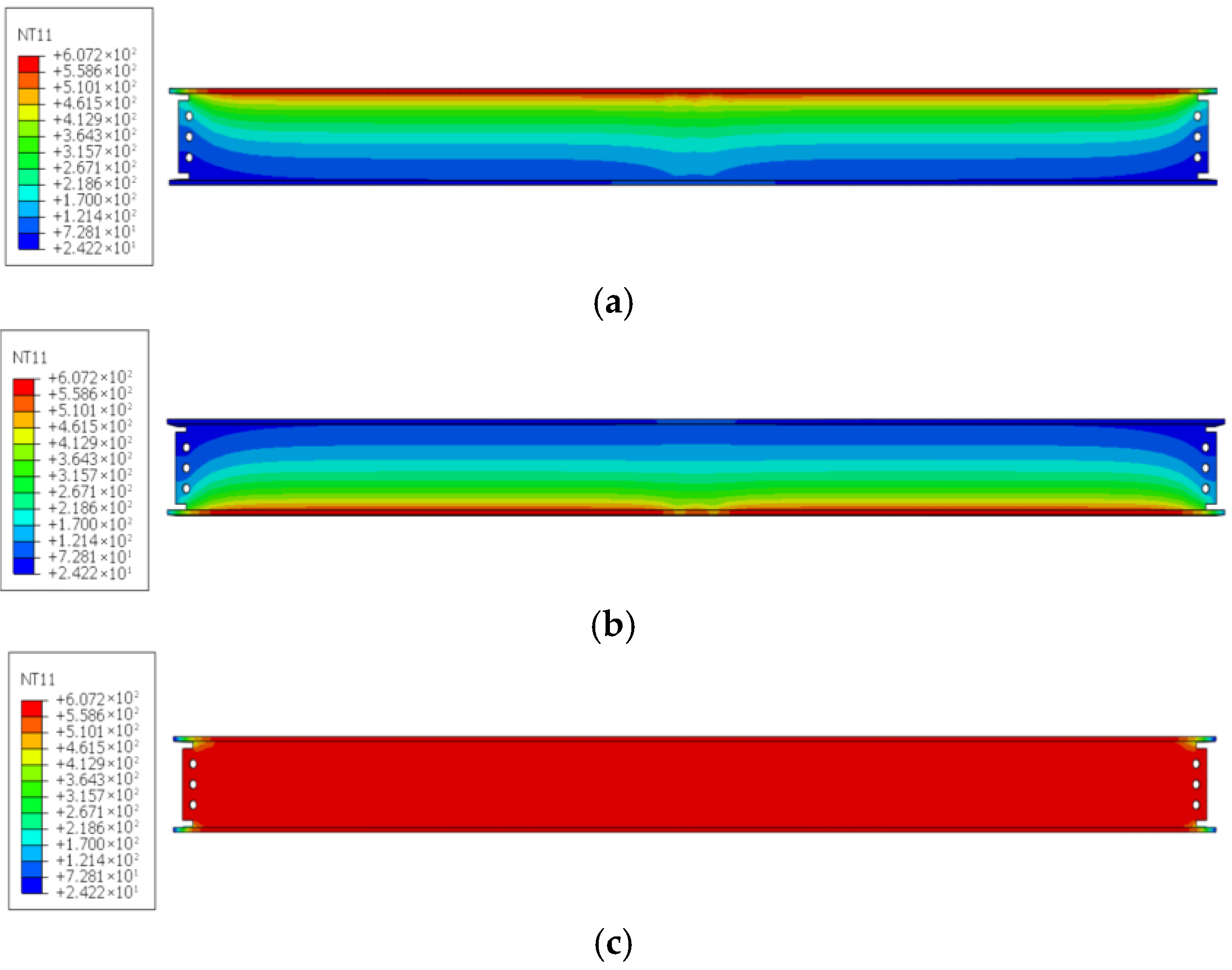
Figure 14a–c show the temperature distribution under these conditions.
Based on the impact force time history curve in
Figure 15, as the fire area shifts upward (from A2 to A1), the local stiffness of the steel at the impact contact surface decreases due to high-temperature softening, resulting in a slight reduction in peak impact force. However, the softening of the lower flange increases the structural deformation capacity.
Compared to A3, the expansion of the fire area significantly worsens structural damage. As shown in
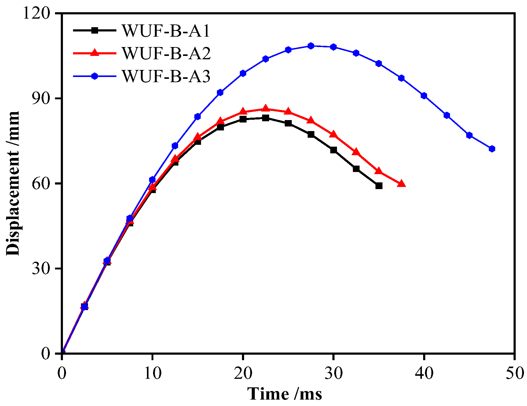
Figure 16, the steel deterioration in the three-sided fire condition (A3) increases, resulting in a 29.8% and 27.1% increase in mid-span deformation compared to A1 and A2, respectively. The impact force time history curve is also notably prolonged. Multiple fire surfaces sharply reduce the structure’s bearing capacity, significantly lowering impact safety.
5.2. Impact Momentum on Structure
To investigate the response mechanism of high-temperature structures under the coupling effect of impact parameters,
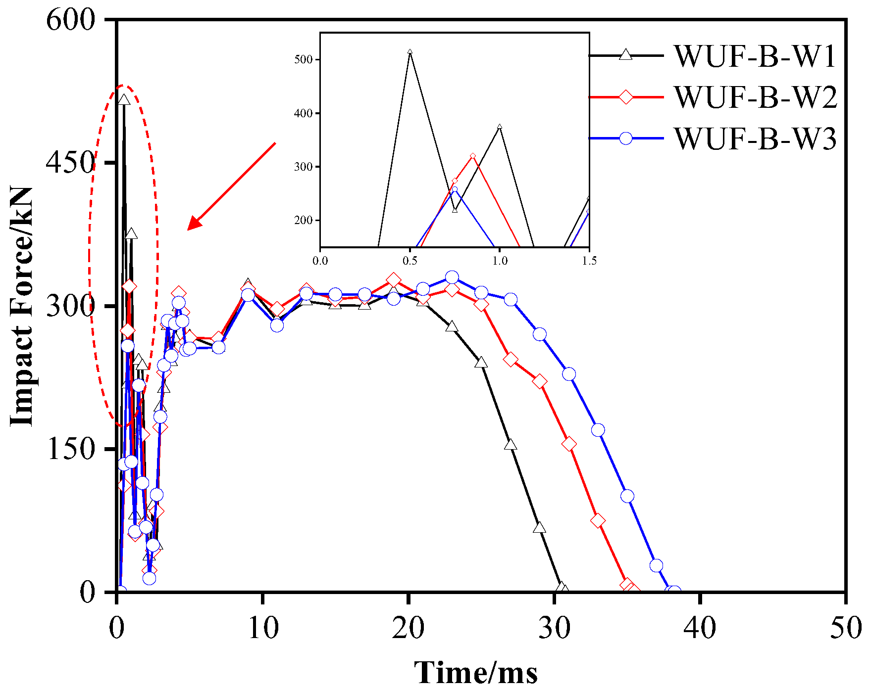
Figure 16 shows the impact force time history curve for different combinations of mass and velocity of the steel frame WUF-B node substructure, with the drop hammer maintaining the same energy at 600 °C. The mass and velocity combinations are: W1 (630 kg, 8.8 m/s), W2 (830 kg, 7.7 m/s), and W3 (980 kg, 7.1 m/s). According to the momentum
, the momentum of different combinations can be calculated, P1 = 5544 kg·m/s, P2 = 6391 kg·m/s, P3 = 6958 kg·m/s.
Figure 17 shows that, with the same impact energy, the peak impact force increases as the impact velocity (and thus momentum) rises. Since the overall stiffness of the structure remains unchanged, the curve shows only slight variation in the impact stability stage with different mass-velocity combinations. However, the impact duration decreases as the hammer’s velocity increases. According to
Figure 18, when the hammer has the same energy, a higher velocity leads to an earlier peak in mid-span displacement, while greater momentum results in a higher peak displacement value.
5.3. Implications for Design and Structural Robustness
The findings of this study highlight several aspects relevant to robustness-based design of steel moment-resisting frames under combined fire and impact conditions. The interaction between temperature and momentum is critical: for the same impact energy, higher impact velocity shortens contact duration and amplifies mid-span displacement, indicating that both energy and momentum should be considered in design checks. Single-sided heating of the lower flange near the impact location significantly reduces resistance, underscoring the need for targeted fire protection in these critical regions. Multi-surface fire exposure further accelerates stiffness loss and should be treated as a worst-case scenario during design assessments. Finally, the steady-state impact force observed at high temperatures governs the deformation profile and may serve as a practical design parameter for improving robustness and mitigating progressive collapse.
6. Theoretical Model of High Temperature Impact Dynamic Response
To address the high cost and technical challenges of impact testing in fire conditions, this study develops an analytical model based on thermal–mechanical coupling stiffness degradation theory to predict the maximum mid-span impact displacement of steel frame structures under localized heating.
The stiffness matrix
K of the beam element is derived from Timoshenko beam theory [
39], accounting for shear deformation and section rotation effects on dynamic response. The high-temperature softening effect is incorporated into the stiffness matrix through a temperature reduction function, as per the Eurocode 3, Part 1-2 [
38], resulting in a temperature-dependent stiffness
K(
T).
where
is the elastic modulus of the material,
is the moment of inertia of the section,
is the test span,
is the initial stiffness at room temperature, 0.002 is the softening coefficient at high temperature, and
is the temperature value of the component surface under the actual fire.
Using the energy method, the theoretical formula for calculating the maximum mid-span displacement in the impact model under fire is simplified as follows:
To verify the maximum mid-span displacement under impact at different temperatures, this section focuses on components above 300 °C, as the displacement difference below 300 °C and room temperature is minimal.
Based on the analysis in
Table 2, the calculation error of the stiffness reduction model from Formula (5) is significant. Since the simulated structure is under single-sided fire, the entire span beam’s stiffness cannot be reduced according to the European code. Therefore, the overall stiffness model needs modification. The revised model, shown in Formulas (7) and (8), replaces the original reduction function with a piecewise function, improving prediction accuracy.
The coefficients in Formulas (7)–(8) were obtained via least-squares fitting to FE-predicted mid-span displacements at 450, 600, and 750 °C. The objective function minimized the relative error between theoretical and numerical results across these temperature levels. The calibrated coefficients reduce the prediction error to within 10% (
Table 2), demonstrating that the segmented stiffness-reduction model captures localized heating effects more accurately than the uniform reduction suggested by Eurocode 3, Part 1-2 [
38].
Using the new stiffness reduction formula, the theoretical mid-span displacement is recalculated and compared with the actual simulation value.
From the comparison in
Table 2, after correction, the prediction error for components at temperatures of 450 °C and above is within the allowable 10% threshold. Therefore, the stiffness degradation model meets the accuracy requirements for dynamic response analysis of steel structures under fire, as verified by simulation data between 450 °C and 750 °C.
7. Conclusions
This paper employs finite element numerical simulations to perform sequential thermal–mechanical coupling analysis of the room temperature impact model and temperature field model. The effects of temperature, fire area, and impact momentum on the dynamic response of the steel frame beam–column structure are analyzed. The following conclusions are drawn:
1. As the temperature of the steel beam’s lower flange rises, the steel frame beam–column structure exhibits systematic performance degradation at high temperatures. When the temperature reaches 600 °C and 750 °C, the peak impact force decreases by 48.4% and 73.3%, respectively, compared to room temperature conditions. The mid-span bending moment increases by 22.8% and 63.3%, and the impact duration lengthens by 34.9% and 112.3%. This phenomenon reflects the high-temperature threshold effect at 600 °C: beyond this critical temperature, steel softening causes a sharp reduction in structural stiffness and a nonlinear decline in energy absorption capacity, leading to a combined degradation of impact resistance, increased deformation, and dynamic response hysteresis.
2. Compared to the lower flange fire benchmark (A2), the upper flange fire on one side (A1) and three sides (A3) causes local stiffness reduction due to thermal softening in the impact contact zone, leading to a decrease in peak impact force. Multiple fire surfaces significantly worsen structural damage: mid-span displacement under three fire conditions is 29.8% and 27.1% greater than under one fire condition, highlighting the cumulative damage effect of increased fire area.
3. When the local temperature of the component reaches 600 °C, maintaining the same impact energy of the falling hammer but varying its momentum (through different mass and speed combinations), a smaller momentum (higher hammer speed) results in a higher peak impact force, quicker mid-span displacement peak, and shorter impact duration.
4. A theoretical model incorporating thermal–mechanical coupling and segmental stiffness reduction is proposed to effectively predict the maximum mid-span displacement of partially fire-exposed steel frames under impact loading. This model addresses the high cost of high-temperature impact testing and the limited accuracy of conventional uniform reduction models under localized fire. Validation across a temperature spectrum shows that the prediction error remains within 10%, significantly enhancing the reliability of dynamic response predictions for steel structures in high-temperature environments.
8. Limitations and Future Work
This study is limited to WUF-B connections under the ISO-834 standard fire curve, without considering residual stresses, geometric imperfections, or temperature-dependent strain-rate effects. These simplifications may restrict the generalization of the findings. Future work should include experimental validation under combined fire–impact loading, consideration of different joint types and fire scenarios, and incorporation of temperature-dependent material properties to enhance predictive accuracy.
Author Contributions
Conceptualization, Z.L. and T.-Q.X.; methodology, Z.L.; software, Y.-T.F.; validation, T.-Q.X.; investigation, Y.-T.F.; resources, Z.L.; data curation, T.-Q.X.; writing—original draft preparation, Y.-T.F.; writing—review and editing, T.-Q.X.; funding acquisition, Z.L. All authors have read and agreed to the published version of the manuscript.
Funding
This research is supported by the Guangxi Natural Science Foundation (Nos. AD25069101 and 2025GXNSFAA069803), and the National Natural Science Foundation of China (No. 52308489).
Data Availability Statement
Dataset available on request from the authors. The raw data supporting the conclusions of this article will be made available by the authors on request.
Conflicts of Interest
The authors declare no conflicts of interest.
References
- ASCE/SEI 7-10; Minimum Design Loads for Buildings and Other Structures. American Society of Civil Engineers (ASCE): Reston, VA, USA, 2010.
- CECS 392:2014; Code for Anti-Collapse Design of Building Structures. China Association for Engineering Construction Standardization (CECS): Beijing, China; China Planning Press: Beijing, China, 2014. (In Chinese)
- Qian, K.; Lan, X.; Li, Z.; Li, Y.; Fu, F. Progressive collapse resistance of two-storey seismic configured steel sub-frames using welded connections. J. Constr. Steel Res. 2020, 170, 106117. [Google Scholar] [CrossRef]
- Qian, K.; Weng, Y.H.; Zhang, L.; Li, Z.; Lan, X. Feasibility of two-storey substructures to equivalently investigate behaviour of multi-storey steel frames. J. Constr. Steel Res. 2023, 210, 108088. [Google Scholar] [CrossRef]
- Federal Emergency Management Agency (FEMA). World Trade Center Building Performance Study: Data Collection, Preliminary Observations, and Recommendations, FEMA 403; FEMA: Washington, DC, USA, 2002.
- Huo, J.; Zhang, J.; Liu, Y.; Fu, F. Dynamic behaviour and catenary action of axially-restrained steel beam under impact loading. Structures 2017, 11, 84–96. [Google Scholar] [CrossRef]
- D’Antimo, M.; Latour, M.; Rizzano, G.; Demonceau, J. Experimental and numerical assessment of steel beams under impact loadings. J. Constr. Steel Res. 2019, 158, 230–247. [Google Scholar] [CrossRef]
- Nasery, M.; Ağcakoca, E.; Yaman, Z. Experimental and numerical analysis of impactor geometric shape effects on steel beams under impact loading. Structures 2020, 27, 1118–1138. [Google Scholar] [CrossRef]
- Wang, R.; Yang, X.; Zhao, H.; Zhai, M.; Chen, W.; Lam, D. Damage evaluation of axial-loaded H-section steel columns during and after impact loading. J. Constr. Steel Res. 2022, 196, 107426. [Google Scholar] [CrossRef]
- Chen, K.; Zhang, Y.; Tan, K. Behaviour of steel beam-column joints subjected to quasi-static and impact loads. J. Constr. Steel Res. 2021, 183, 106721. [Google Scholar] [CrossRef]
- Wang, H.; Huo, J.; Elchalakani, M.; Liu, Y.; Zhang, S. Dynamic performance of retrofitted steel beam-column connections subjected to impact loadings. J. Constr. Steel Res. 2021, 183, 106732. [Google Scholar] [CrossRef]
- Wang, H.; Huo, J.; Liu, Y.; Wang, N.; Elchalakani, M. Experimental and numerical study on impact behavior of beam-column substructures of steel frame. Structures 2021, 29, 14–29. [Google Scholar] [CrossRef]
- Wang, H.; Yang, B.; Zhou, X.; Kang, S. Numerical analyses on steel beams with fin-plate connections subjected to impact loads. J. Constr. Steel Res. 2016, 124, 101–112. [Google Scholar] [CrossRef]
- Yang, B.; Wang, H.; Yang, Y.; Kang, S.; Zhou, X.H.; Wang, L. Numerical study of rigid steel beam-column joints under impact loading. J. Constr. Steel Res. 2018, 147, 62–73. [Google Scholar] [CrossRef]
- Wang, H.; Tan, K.; Yang, B. Experimental tests of steel frames with different beam-column connections under falling debris impact. J. Struct. Eng. 2020, 146, 04019183. [Google Scholar] [CrossRef]
- Wang, H.; Tan, K.; Yang, B. Impact resistance of steel frames with different beam–column connections subject to falling-floor impact on various locations. J. Struct. Eng. 2021, 147, 04021017. [Google Scholar] [CrossRef]
- Ramesh, S.; Choe, L.; Zhang, C. Experimental investigation of structural steel beams subjected to localized fire. Eng. Struct. 2020, 218, 110844. [Google Scholar] [CrossRef]
- Guo, Z.; Huang, S. Behaviour of restrained steel beam with reduced beam section exposed to fire. J. Constr. Steel Res. 2016, 122, 434–444. [Google Scholar] [CrossRef]
- Wu, Y.; Fan, S.; He, B.; Liu, M.; Zhou, H. Research on the fire resistance design of high-strength steel hollow columns under axial compression. Eng. Struct. 2021, 234, 111943. [Google Scholar] [CrossRef]
- Fan, S.; Duan, S.; Zeng, S.; Wu, Y.; Ding, R. Experimental study and numerical simulation analysis of the bolted-welded hybrid connection joint of steel frame under fire. Structures 2022, 41, 77–98. [Google Scholar] [CrossRef]
- Dai, X.H.; Wang, Y.; Bailey, C. An experimental study of structural behavior of joints in restrained steel frames in fires. In Proceedings of the Application of Structural Fire Design International Conference, Prague, Czech Republic, 19–20 February 2009; pp. 350–355. [Google Scholar]
- Dai, X.H.; Wang, Y.C.; Bailey, C.G. Numerical modelling of structural fire behaviour of restrained steel beam–column assemblies using typical joint types. Eng. Struct. 2010, 32, 2337–2351. [Google Scholar] [CrossRef]
- Wang, Y.; Dai, X.; Bailey, C. An experimental study of relative structural fire behaviour and robustness of different types of steel joint in restrained steel frames. J. Constr. Steel Res. 2011, 67, 1149–1163. [Google Scholar] [CrossRef]
- Guo, Z.; Xu, Z.; Lin, H.; Zheng, Z.; Su, H.; Chen, J. Experimental tests of post-fire beam-column assemblies with WUF-B connections against progressive collapse. J. Constr. Steel Res. 2022, 192, 107249. [Google Scholar] [CrossRef]
- Guo, Y.X.; Xi, F.; Tan, Y.H.; Liu, F.; Hu, Y.C. Effects of connection types and elevated temperature on the impact behaviour of restrained beam in portal steel frame. Def. Technol. 2023, 25, 174–191. [Google Scholar] [CrossRef]
- Jiang, B.; Li, G.; Li, L.; Izzuddin, B. Experimental studies on progressive collapse resistance of steel moment frames under localized furnace loading. J. Struct. Eng. 2018, 144, 04017190. [Google Scholar] [CrossRef]
- Lou, G.; Wang, C.; Jiang, J.; Wang, L.; Li, G. Fire tests on full-scale steel portal frames against progressive collapse. J. Constr. Steel Res. 2018, 145, 137–152. [Google Scholar] [CrossRef]
- Lou, G.; Wang, C.; Jiang, J.; Jiang, Y.; Wang, L. Experimental and numerical study on thermal-structural behavior of steel portal frames in real fires. Fire Saf. J. 2018, 98, 48–62. [Google Scholar] [CrossRef]
- Oliveira, P.N.; Fonseca, E.M.M.; Campilho, R.D.S.G.; Piloto, P.A.G. Analytical Equations Applied to the Study of Steel Profiles Under Fire According to Different Nominal Temperature-Time Curves. Math. Comput. Appl. 2021, 26, 48. [Google Scholar] [CrossRef]
- Oliveira, P.N.; Fonseca, E.M.M.; Campilho, R.D.S.G. Easy trends to analyse structural profiles: Lumped capacitance vs simplified equation. Int. J. Saf. Secur. Eng. 2020, 10, 625–629. [Google Scholar] [CrossRef]
- Szymczak-Graczyk, A. Rectangular plates of a trapezoidal cross-section subjected to thermal load. IOP Conf. Ser. Mater. Sci. Eng. 2019, 603, 032095. [Google Scholar] [CrossRef]
- BS 4-1:2005; Structural Steel Sections. Specification for Hot-Rolled Sections. British Standards Institution (BSI): London, UK, 2005.
- Mostofi, T.M.; Babaei, H.; Alitavoli, M. Theoretical analysis on the effect of uniform and localized impulsive loading on the dynamic plastic behaviour of fully clamped thin quadrangular plates. Thin-Walled Struct. 2016, 109, 367–376. [Google Scholar] [CrossRef]
- Suman, S.; Samanta, A.; Singh, P.K. Behaviour, design, and reliability of monosymmetric I-beams at elevated temperature. Structures 2024, 63, 106342. [Google Scholar] [CrossRef]
- ISO 834-1:1999; Fire Resistance Tests—Elements of Building Construction—Part 1: General Requirements. International Organization for Standardization (ISO): Geneva, Switzerland, 1999.
- EN 1991-1-2:2002/AC:2009; Eurocode 1: Actions on Structures—Part 1-2: General Actions—Actions on Structures Exposed to Fire. European Committee for Standardization (CEN): Brussels, Belgium, 2002.
- EN 1993-1-1:2005/A1:2014; Eurocode 3: Design of Steel Structures—Part 1-1: General Rules and Rules for Buildings. European Committee for Standardization (CEN): Brussels, Belgium, 2005.
- EN 1993-1-2:2005; Eurocode 3: Design of Steel Structures—Part 1-2: General Rules—Structural Fire Design. European Committee for Standardization (CEN): Brussels, Belgium, 2005.
- Timoshenko, S.P. Strength of Materials, Volume II: Advanced Theory and Problems, 3rd ed.; D. Van Nostrand Company: New York, NY, USA, 1956. [Google Scholar]
Figure 1.
Finite element model of steel frame.
Figure 1.
Finite element model of steel frame.
Figure 2.
Comparison of impact force and mid-span deflection time history curves: (a) Validation of impact force time-course curves. (b) Validation of displacement time-course curves.
Figure 2.
Comparison of impact force and mid-span deflection time history curves: (a) Validation of impact force time-course curves. (b) Validation of displacement time-course curves.
Figure 3.
WUF-B damage modes.
Figure 3.
WUF-B damage modes.
Figure 4.
Temperature rise time curves for different test points and finite element results.
Figure 4.
Temperature rise time curves for different test points and finite element results.
Figure 5.
Comparison of destructive modes.
Figure 5.
Comparison of destructive modes.
Figure 6.
Temperature field model.
Figure 6.
Temperature field model.
Figure 7.
Impact force time history curves at different temperatures.
Figure 7.
Impact force time history curves at different temperatures.
Figure 8.
Time history curves of mid-span displacement at different temperatures.
Figure 8.
Time history curves of mid-span displacement at different temperatures.
Figure 9.
Time history curves of axial forces on components at different temperatures.
Figure 9.
Time history curves of axial forces on components at different temperatures.
Figure 10.
Time history curves of catenary forces on components at different temperatures.
Figure 10.
Time history curves of catenary forces on components at different temperatures.
Figure 11.
Time history curves of reaction forces at component supports at different temperatures.
Figure 11.
Time history curves of reaction forces at component supports at different temperatures.
Figure 12.
Impact force-displacement of different components.
Figure 12.
Impact force-displacement of different components.
Figure 13.
Plastic strain cloud diagrams of different components: (a) W025; (b) W150; (c) W300; (d) W450; (e) W600; (f) W750.
Figure 13.
Plastic strain cloud diagrams of different components: (a) W025; (b) W150; (c) W300; (d) W450; (e) W600; (f) W750.
Figure 14.
Schematic diagram of different fire-exposed areas of the component: (a) single-sided fire on the upper flange; (b) single-sided fire on the lower flange; (c) three-sided fire.
Figure 14.
Schematic diagram of different fire-exposed areas of the component: (a) single-sided fire on the upper flange; (b) single-sided fire on the lower flange; (c) three-sided fire.
Figure 15.
Impact force time history curves for different fire-exposed areas.
Figure 15.
Impact force time history curves for different fire-exposed areas.
Figure 16.
Time history curves of mid-span displacement for different fire-exposed areas.
Figure 16.
Time history curves of mid-span displacement for different fire-exposed areas.
Figure 17.
Impact force time history curves of components under different momenta.
Figure 17.
Impact force time history curves of components under different momenta.
Figure 18.
Time history curves of mid-span displacement of components under different moment conditions.
Figure 18.
Time history curves of mid-span displacement of components under different moment conditions.
Table 1.
Basic parameters and results of components.
Table 1.
Basic parameters and results of components.
Specimen
Identifier | T/°C | Eg/kJ | Eg/Ei | Fmax/kN | tmax/ms | Umax/mm |
|---|
| WUF-B025 | 25 | 18.8 | 76.4% | 575.2 | 29.7 | 70.3 |
| WUF-B150 | 150 | 18.5 | 75.2% | 399.5 | 29.7 | 70.1 |
| WUF-B300 | 300 | 18.2 | 74.0% | 324.5 | 30.5 | 70.3 |
| WUF-B450 | 450 | 18.3 | 74.4% | 283.7 | 32.9 | 75.3 |
| WUF-B600 | 600 | 18.5 | 75.2% | 204.5 | 35.7 | 86.3 |
| WUF-B750 | 750 | 18.0 | 73.2% | 105.4 | 46.8 | 114.8 |
Table 2.
Theoretical error analysis of maximum displacement at mid-span.
Table 2.
Theoretical error analysis of maximum displacement at mid-span.
| Temperature | Mid-Span Deflection | Predicted Value | Corrected Predicted Value | Error (%) | Error After Correction (%) |
|---|
| 450 °C | 75.3 | 121.0 | 81.2 | 60.7 | 7.8 |
| 600 °C | 86.3 | 141.4 | 82.6 | 63.9 | 4.3 |
| 750 °C | 114.8 | 161.0 | 122.5 | 40.2 | 6.7 |
| Disclaimer/Publisher’s Note: The statements, opinions and data contained in all publications are solely those of the individual author(s) and contributor(s) and not of MDPI and/or the editor(s). MDPI and/or the editor(s) disclaim responsibility for any injury to people or property resulting from any ideas, methods, instructions or products referred to in the content. |
© 2025 by the authors. Licensee MDPI, Basel, Switzerland. This article is an open access article distributed under the terms and conditions of the Creative Commons Attribution (CC BY) license (https://creativecommons.org/licenses/by/4.0/).

