Abstract
To address the cracking problem caused by the weak tensile performance of concrete, this study investigates the failure mechanisms of basalt fiber-reinforced concrete under different fiber contents, single-blend, and mixed-blend schemes through splitting tensile tests and discrete element method (DEM) simulations. The tests employ 0.1–0.3% of 18 mm single-blend fibers and 6 mm:12 mm:18 mm (3:4:3) mixed-blend schemes, and PFC software is used to simulate crack propagation in fiber-reinforced concrete. The results show that the optimal 0.2% content of 18 mm single-blend fibers enhances the splitting tensile strength by 10.8%, whereas excessive 0.3% content reduces the strength by 7.8% due to poor dispersion. The mixed-blend scheme, via gradient crack-resisting effects of multi-scale fibers, increases the strength by 7.43% compared with the single-blend group at the same fiber content. DEM simulations reveal that fibers delay crack propagation through stress concentration transfer: single-blend fibers render tortuous crack paths, while mixed-blend fibers form three-dimensional crack networks, transforming the failure energy dissipation mode from single pull-out to multi-stage consumption. This research provides theoretical basis and optimization strategies for the anti-cracking design of basalt fiber-reinforced concrete.
1. Introduction
With the continuous advancement of infrastructure construction, the consumption of concrete as a key building material has increased year by year. Large-scale projects such as bridges, tunnels, and high-rise buildings have placed unprecedented demands on the performance and durability of concrete. Harsh environments, including extreme temperature variations, chemical erosion, and freeze–thaw cycles, can cause severe damage to concrete structures, with cracking being the most prominent issue [1,2]. Once cracks occur, they not only weaken the bearing capacity of structures but also accelerate the ingress of harmful substances, leading to reduced concrete strength and even overall structural failure, posing significant challenges to the long-term safe operation of infrastructure [3,4]. From a material mechanics perspective, concrete exhibits high compressive strength but extremely low tensile strength, which is a fundamental cause of its durability defects. Under long-term loading and environmental erosion, minor defects within concrete gradually expand into cracks, accelerating material degradation, as shown in Figure 1. To address this issue, the incorporation of high-performance fiber materials into concrete has become a research hotspot. As a new type of high-performance inorganic non-metallic material, basalt fiber demonstrates great potential in improving concrete performance due to its high strength, high modulus, good chemical stability, and high-temperature resistance [5,6]. The addition of basalt fiber to concrete can effectively inhibit the initiation and propagation of cracks, enhance the toughness and ductility of concrete, and thus significantly improve the durability of concrete structures in harsh environments, presenting important engineering application value and practical significance.
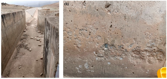
Figure 1.
Concrete cracking phenomenon in a certain channel project. (a) The overall cracking situation of the channel; (b) cracking condition on the channel surface.
Extensive experimental, theoretical, and numerical studies on the mechanical properties of basalt fiber-reinforced concrete have been conducted by scholars. Experimental studies can intuitively reflect the mechanical characteristics of basalt fiber-reinforced concrete. For example, Yang et al. [7] investigated the effects of basalt fiber content on the compressive mechanical properties and damage mechanisms of concrete using uniaxial compression based on DIC. Shao et al. [8] studied the mechanical behavior of basalt fiber-reinforced coral concrete (BFRCC) under uniaxial compression to address the poor mechanical properties of coral concrete. Liu et al. [9] carried out experimental research on the shear performance of deep beams made of basalt fiber-reinforced polymer (BFRP) bars and basalt fiber-reinforced concrete (BFRC) without shear reinforcement. Xie et al. [10] investigated the dynamic mechanical properties of basalt fiber-reinforced concrete (BFRC) under different strain rates, basalt fiber contents, and lengths through Split Hopkinson Pressure Bar (SHPB) tests. Xiao et al. [11] studied the effects of stress ratio, basalt fiber content (0–1.2%), and concrete strength grade (C30, C40) on the mechanical properties of basalt fiber-reinforced coral aggregate concrete (BFRCC) through biaxial compression tests. Niu et al. [12] experimentally investigated the influences of BFC (0–0.2%) on compressive/splitting tensile strength and durability (chloride ion content, water absorption, and microstructure) of coral aggregate concrete. However, experimental studies can only provide apparent phenomena of the failure of basalt fiber-reinforced concrete, making it difficult to deeply explore the mechanical mechanisms behind the failure. Theoretical studies, based on experimental research, summarize and refine fracture criteria or damage evolution models for concrete. For example, Guo et al. [13] explored the mechanical characteristics and fracture behavior of rock–concrete composites with two parallel prefabricated cracks under uniaxial compression, and established a corresponding energy evolution model. Wang et al. [14] constructed a prediction model for the flow performance of self-compacting concrete (SCC) in rock skeletons based on the Bingham fluid model and fractal theory. Xu et al. [15] proposed a unified aggregate shape descriptor based on the superellipsoid, constructed a three-phase meso-structure of concrete using random static and dynamic packing models, and derived a closed-form expression for the ITZ volume fraction using the theory of the nearest surface distribution function. Ince [16] derived the stress intensity factor formula and expressions for CMOD, COD, etc., for semi-circular bending (SCB) specimens using the finite element method (FEM) based on linear elastic fracture mechanics (LEFM) theory. Wang et al. [17] constructed a theoretical model for the fracture toughness of concrete considering the actual critical crack length based on the stress intensity factor (SIF) competition mechanism. However, theoretical studies are based on a series of assumptions, making it difficult to accurately describe the mechanical characteristics of random fibers inside BFRC in complex situations.
Numerical simulation, known as the “third means” of scientific research, overcomes the limitations of experimental and theoretical studies and can simulate the damage evolution process of BFRC under complex conditions. The finite element method was first applied to the mechanical simulation of concrete. For example, Zhang et al. [18] studied the uniaxial compression behavior of concrete before and after freeze–thaw cycles through experiments and three-dimensional meso-numerical simulations, and established a stress-strain constitutive model considering the freeze–thaw damage variable. Zhang et al. [19] proposed a finite element simulation method for analyzing the dynamic fracture of concrete in mixed mode I–II based on the initial fracture toughness, extracted the dynamic stress intensity factor through the interaction integral method, and implemented crack propagation tracking combined with field variable transfer technology. Huang et al. [20] proposed a coupling algorithm of cavity expansion theory and finite element method to simulate the dynamic process of projectile penetration into reinforced concrete. Liang et al. [21] proposed a peridynamics–finite element coupling method (PDFEM) for multi-bond element stiffness matrices, enabling the collaborative simulation of crack propagation and stress state in concrete materials by introducing the finite element stiffness matrix into peridynamics. However, the finite element method faces challenges in dealing with crack propagation, such as grid dependency issues (e.g., low computational efficiency due to frequent grid redivision), limited simulation accuracy for complex crack paths (such as bifurcation and tortuosity), and difficulties in accurately describing discontinuous behaviors during the fracture process based on the assumption of a continuous medium. Additionally, traditional finite element methods also face challenges in energy conservation and local stress singularity treatment during dynamic crack propagation. Subsequently, to overcome the shortcomings of the finite element method in handling discontinuity, scholars proposed the XFEM. For example, Haghani et al. [22] proposed a new method for seismic failure analysis of concrete gravity dams based on the XFEM, combining the α-method time integration and dynamic stress intensity factor, and simulating crack behavior and dam–foundation–reservoir interaction using the penalty function method and zero-thickness contact elements. Faron et al. [23] used the XFEM to perform nonlinear numerical simulations of bending and shear crack propagation in reinforced concrete beams without transverse reinforcement, analyzing the smeared crack and discrete crack propagation in haunched and non-haunched beams. Aghajanzadeh et al. [24] proposed a method for simulating the fracture process of concrete by combining the extended finite element method (XFEM) with a fixed smeared crack model. Benvenuti et al. [25] proposed a three-dimensional mechanism-based regularized extended finite element method (XFEM) for simulating intermediate flexural debonding of FRP plates from concrete beams. However, the extended finite element method still has some limitations in handling crack propagation: first, the simulation accuracy and computational efficiency for complex three-dimensional cracks (such as twisting and bifurcation) are low, and the implementation of high-order shape functions and enrichment strategies is complex; second, the problems of mass conservation and energy dissipation in dynamic crack propagation still need improvement, especially under high-speed impact or dynamic loading conditions; third, challenges remain in compatibility with non-enriched regions and multi-field coupling (such as fluid–structure interaction fracture). The discrete element method (DEM), a meshless method different from the finite element method, discretizes the computational domain into a series of particles and assigns corresponding contact models to the particles, thus enabling the simulation of various complex fracture processes. For example, Li et al. [26] proposed a three-dimensional discrete element model (3D DEM) with a softening effect to study the fracture behavior of concrete. Peng et al. [27] constructed a heterogeneous model of concrete based on porosity through the discrete element method (DEM) to study the influence of aggregate distribution on its cracking behavior. Knak et al. [28] developed a discrete element model (DEM) to simulate the propagation of ultrasonic waves in concrete. Yu et al. [29] simulated the deterioration characteristics of solids under freeze–thaw cycles based on the discrete element method. The discrete element method has significant advantages in handling crack propagation, as it can naturally simulate discontinuous behaviors during material fracture, such as crack initiation, propagation, and bifurcation, without the need to predefine crack paths or redivide grids frequently. Based on the discrete characteristics of particles or blocks, it can accurately describe the movement and interaction of fragments after fracture, which is suitable for complex problems such as brittle material fragmentation and rock fracture. In addition, DEM can intuitively reflect the energy dissipation mechanism during dynamic crack propagation, making it more suitable for simulating large-scale failure and discretized failure problems. Therefore, it can be applied to the simulation of BFRC.
Based on the shortcomings of previous studies, basalt fiber is added to traditional concrete to improve its tensile performance. In the experimental process, single-blend and mixed-blend schemes are adopted to carry out splitting tensile tests, and the optimal scheme is obtained through comparison. Based on PFC software, a method for generating random basalt fibers is realized within its framework. DEM simulations of the splitting failure process of BFRC under different schemes are carried out to reproduce the peak strength changes and failure processes of basalt fiber-reinforced concrete. The core innovation of this study lies in the following: through the particle discrete characteristics of the discrete element method (DEM), it more systematically realizes the full-process tracking of crack evolution in basalt fiber-reinforced concrete under splitting tensile loads. It not only quantifies the tortuous effect of single-blend fibers on crack paths, but also reveals the law of stress concentration transfer when mixed-blend fibers form a network, as well as the transformation mechanism of energy dissipation from “single pull-out” to “multi-stage consumption”. This simulation method makes up for the deficiencies of experimental and traditional numerical methods in the analysis of micro-mechanisms [30,31] and provides theoretical support from macro-performance to micro-mechanism for anti-cracking [32,33].
2. Specimen Preparation, Test Equipment, and Scheme
2.1. Specimen Preparation
The specimen preparation processes is as follows:
- (1)
- Material weighing: Cement, water, sand, aggregate, water reducer, and basalt fibers were weighed according to the calculated mix proportions. The basalt fibers are shown in Figure 2.
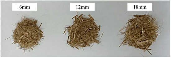 Figure 2. Schematic diagrams of basalt fibers of different lengths.
 - (2)
- Concrete mixing: The weighed stones, sand, and cement were sequentially put into a concrete mixer. When no fiber or 0.1% fiber was added, dry mixing was conducted for 30 s. To ensure uniform dispersion of basalt fibers in concrete the dry mixing time was extended to 60 s and 90 s for 0.2% and 0.3% dosages, respectively, as determined through multiple tests. During mixing, basalt fibers were evenly sprinkled, and the mixer was started again for 90 s of wet mixing. Basalt fibers of different lengths are shown in Figure 2.
- (3)
- Pouring and vibrating: After cleaning the mold, a release agent was evenly applied to its surface. The mixed concrete was poured into the mold, fixed on a vibrating table and vibrated for 30 s, then the excess part beyond the mold was scraped off with a trowel, and vibration was continued until the concrete volume stabilized.
- (4)
- Curing treatment: The surface of the specimen was leveled with a trowel along the horizontal direction, marked with a marker pen. The specimens were demolded 24 h after casting and then cured in the curing room until the age of 28 days.
2.2. Test Equipment and Scheme
Concrete materials have the remarkable characteristic of “high compressive strength and low tensile strength”, with tensile strength only 1/10 to 1/20 of the compressive strength. To accurately evaluate the improvement effect of basalt fibers on the tensile performance of concrete, a splitting tensile test was adopted in this study to replace the traditional compression test. This method applies a transverse compressive load to a cubic specimen and uses the principle of stress concentration to generate tensile stress in the axial direction of the specimen, so as to indirectly determine the tensile strength of the material. To explore the effects of different basalt fiber contents and single-blend/mixed-blend methods on the tensile performance of concrete, seven test schemes were designed (Table 1). Among them, Scheme A was the blank control group without any basalt fiber; Schemes B1–B3 were single-blend groups with only 18 mm basalt fibers added, with dosages of 0.1%, 0.2%, and 0.3%, respectively; Schemes C1–C3 were mixed-blend groups with basalt fibers of 6 mm:12 mm:18 mm mixed in the ratio of 3:4:3, with dosages of 0.1%, 0.2%, and 0.3%, respectively. All specimens were made into standard cubes of 150 mm × 150 mm × 150 mm, and the splitting tensile test was carried out after curing to the age of 28 days.

Table 1.
Test schemes of basalt fiber-reinforced concrete.
The splitting tensile test of concrete cube specimens with different basalt dosages was carried out, as shown in Figure 3. The test steps were as follows:
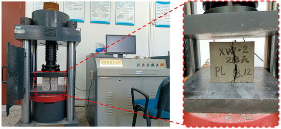
Figure 3.
Test equipment and loading methods.
- (1)
- Specimens were prepared and cured according to the regulations in 2.1, with 3 specimens in each group. The compressive strength used cubic specimens with a side length of 150 mm and aggregates larger than 40 mm in particle size were removed by wet screening before molding.
- (2)
- When the specified test age was reached, the specimens were taken out from the curing room and covered with wet cloth to keep the specimens in a humid state.
- (3)
- Before the test, the specimens were wiped clean, the appearance was checked, and the width was measured at the middle and vertical positions of the upper and lower bearing surfaces (accurate to 1 mm). The appearance and deviation of the specimens should meet the requirements of the specification.
- (4)
- The upper and lower pressure plates of the testing machine were wiped clean. The specimen was placed in the middle of the lower pressure plate of the testing machine, with the side surface during molding as the bearing surface. If necessary, steel backing plates were added between the upper and lower pressure plates of the testing machine and the specimen, and a steel ball seat was clamped at the middle position between the upper pressure plate and the specimen.
- (5)
- The loading speed of the testing machine was set to 18–30 MPa/min. The testing machine was started, and when the upper pressure plate was about to contact the backing plate, the ball seat was adjusted to make the specimen uniformly compressed. The testing machine was made to load continuously and uniformly until the specimen was damaged, and the damage load (P, accurate to 0.01 kN) was recorded. In the case of manual control of the loading speed, when the specimen was close to damage and began to deform rapidly, the adjustment of the test machine oil door was stopped until the specimen was damaged.
- (6)
- After shutdown, the specimen was removed, and the morphology of the damaged specimen was observed. If an obvious phenomenon of non-uniform compressive failure was observed, it was recorded.
3. PFC Principles
3.1. Parallel Bond Model
DEM has been widely applied in the research of rock failure mechanisms due to its capability to capture discontinuous failures and multi-scale damages in concrete and rock materials. PFC2D 6.0 was selected as the numerical simulation tool in this study, which solves the equilibrium and displacement by following the motion between particles. The PB model is adopted as the material for numerical simulation, and its principle is shown in Figure 4.
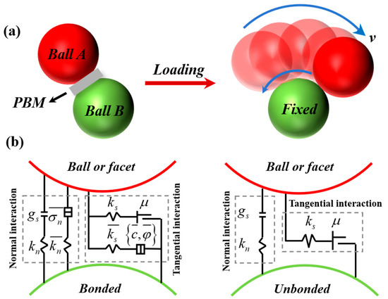
Figure 4.
The principle of parallel linear bonding model. (a) Parallel bonding model and (b) the activated and inactive states of bonding.
The PB model can be regarded as introducing a rigid cementitious material with stiffness between two contact units. When the parallel bond model is created, the relative motion between particles generates forces and moments, transitioning to a bonded state. When the maximum stress between particles exceeds the bond strength, the parallel bond breaks, a crack is generated, and it becomes an unbonded state, only able to bear tensile forces and frictional forces between particles.
The forces and moments applied to the PB model are as follows [29]:
Figure 5 shows the strength envelope for the failure of the PB model. When a contact element is loaded, if the tensile stress borne by the bond exceeds the ultimate tensile strength, i.e., , tensile failure occurs. If the bond does not break due to tensile stress, the ultimate shear strength is enhanced. When the shear stress borne by the bond exceeds the ultimate shear strength, i.e., , shear failure occurs (with tensile force being negative and compressive force being positive) [29]:
where represents the average tensile stress on the bond, represents the contact area of particle bonding, represents the bond strength, and represents the bond friction angle.
Figure 5.
Parallel bonding model strength failure envelope.
3.2. Fiber Generation Method
The fibers in the simulated splitting failure process of fiber-reinforced concrete are generated using the clump command in PFC2D 6.0. As illustrated in Figure 6, a clump is a rigid assembly composed of multiple particles. The generation process involves defining a clump template first, arranging single particles in a straight line, extracting and converting the position information of these particles into the particle positions of the clump template, and finally deleting the original particles while retaining the clump template. This method enables precise control over the shape and size of the fibers.
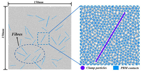
Figure 6.
Schematic diagram of the fiber model.
The numerical model shares the same dimensions as the test specimens. The overall model employs the PB model, with different fiber contents set according to varying test schemes. Fibers are generated at random positions within the specimen. The servo system applies pressure to the walls to bring the fibers into contact with surrounding particles, adjusting the particle spacing to a non-overlapping state.
3.3. Numerical Model and Parameters
As shown in Figure 7, the loading method in this study uses loading bars with a loading speed of 0.05 mm/s. Loading can be performed after the model is generated. The parameters of Scheme A specimens are calibrated in this study through a trial-and-error method, where the mesoscopic parameters of the model are adjusted to make the numerical simulation results close to the test results. The final failure modes of both the numerical simulation and the test specimens show a top-down tensile failure zone, indicating the reliability of the numerical simulation.
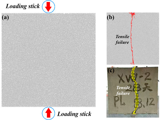
Figure 7.
Numerical model and loading results. (a) Loading rod settings; (b) numerical simulation results; (c) test results.
Figure 8 shows the corresponding parameter calibration result curve, which is divided into four stages: (1) the pore compaction stage: due to the pores in the specimen, internal contacts cannot be fully stressed, resulting in a non-linear load-displacement curve at this stage; (2) the linear elastic deformation stage: the specimen is compacted, the load-displacement follows Hooke’s law with a constant slope, and no cracks are generated; (3) the plastic deformation stage: the slope of the load-displacement curve fluctuates, cracks begin to appear, but the curve still trends upward until reaching the peak strength; (4) the failure stage: the curve starts to decline, the number of cracks increases sharply, and complete failure occurs finally. The peak strength from the numerical simulation is 67,653 N, while the test results is 65,351 N; these values are close, and their failure modes are similar. It can be seen that the mechanical properties of the numerical model with calibrated parameters are similar to those of the test specimens in this study, so it can be used to simulate the uniaxial splitting of fiber-reinforced concrete specimens. The calibrated mesoscopic parameters are shown in Table 2.
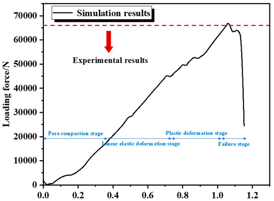
Figure 8.
Parameter calibration results.
Table 2.
Calibrated mesoscopic parameters.
4. Analysis of Test and Numerical Simulation Results
4.1. Crack Propagation Morphology Analysis
Figure 9 presents the numerical simulation and experimental results of crack propagation and final failure morphology for basalt fiber-reinforced concrete under different schemes, revealing distinct patterns induced by fiber content, length, and blending strategies.
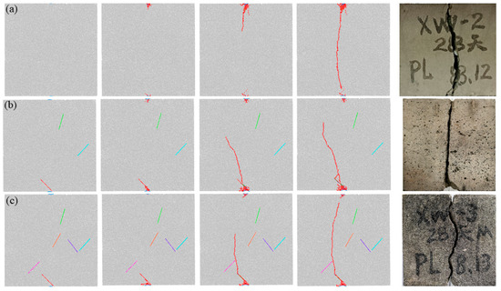
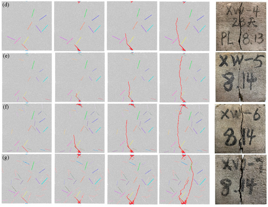
Figure 9.
The splitting failure forms. (a) Option A, (b) Scheme B1, (c) Scheme B2, (d) Scheme B3, (e) Scheme C1, (f) Scheme C2, and (g) Scheme C3.
The control group (Scheme A, no fibers) exhibits typical brittle failure: microcracks initiate at internal defects under load, rapidly coalescing into a single straight main crack that penetrates the specimen vertically. The failure surface is flat, with minimal branching, reflecting unobstructed crack propagation due to the absence of fiber bridging, leading to sudden loss of bearing capacity.
For single-blend 18 mm fiber groups (B1–B3), crack propagation is significantly modulated by the fiber content. At 0.1% (B1), the fibers form sparse unidirectional bridges, slowing microcrack expansion and inducing slight tortuosity in the main crack path. The failure surface shows limited fiber pull-out traces, indicating partial stress transfer. At the optimal 0.2% (B2), denser fiber distribution enhances bridging effects, resulting in highly tortuous crack paths with frequent deflection around fibers. Abundant fiber deformation and pull-out marks on the failure surface confirm effective energy dissipation. At 0.3% (B3), excessive fiber content causes localized agglomeration, leading to uneven stress distribution. While crack propagation is initially delayed by dense fiber networks, uneven dispersion triggers premature interfacial failure in some regions, resulting in a mixed morphology of tortuous paths and localized brittle splits.
Mixed-blend groups (C1–C3, 6 mm:12 mm:18 mm = 3:4:3) exhibit superior crack resistance through multi-scale synergies. At 0.1% (C1), short fibers (6 mm) fill microvoids to inhibit early crack initiation, while medium (12 mm) and long (18 mm) fibers form a preliminary three-dimensional network, deflecting cracks into non-linear paths. The failure surface displays pull-out traces of fibers across all lengths, indicating gradient stress redistribution. At 0.2% (C2), the densified multi-scale network transforms crack propagation into a complex bifurcated pattern: short fibers arrest microcracks, medium fibers bridge growing cracks, and long fibers prevent macrocrack penetration, resulting in a fragmented failure surface with extensive branching. At 0.3% (C3), despite marginal agglomeration, the hierarchical fiber structure maintains effective crack branching; the failure morphology is characterized by a dense network of interconnected microcracks, with energy dissipation distributed across multiple fiber–matrix interfaces rather than localized zones.
Collectively, these observations demonstrate that mixed-blend fibers outperform single-blend counterparts in suppressing crack propagation, attributed to their ability to form three-dimensional constraint networks. Within each blending category, crack resistance peaks at 0.2% fiber content, with excessive dosage (0.3%) undermining performance due to dispersion issues.
Figure 10 shows the splitting tensile strength law of concrete specimens under different schemes, with the strength conversion formula
where fts is the splitting tensile strength, P is the failure load, and A is the loading area of the specimen.
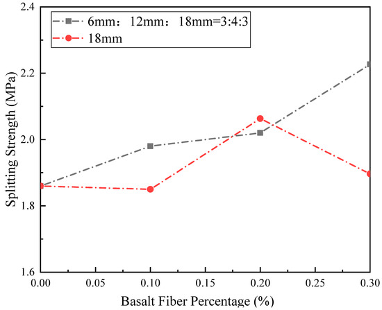
Figure 10.
The splitting tensile strength law of concrete specimens under different schemes.
As can be seen from the figure, Scheme A (without fibers) has the lowest strength, with a measured value of approximately 1.86 MPa. As the 18 mm fiber content increases from 0.1% (B1) to 0.3% (B3), the strength first increases and then stabilizes, peaking at 2.06 MPa in B2 (0.2% content), representing a 10.8% increase over Scheme A. Excessive 0.3% content (B3) reduces strength by 7.8% due to decreased fiber dispersion and local agglomeration-induced stress concentration.
The mixed-blend group (6 mm:12 mm:18 mm = 3:4:3) generally exhibits higher strength than the single-blend group at the same content, attributed to the gradient crack resistance of multi-scale fibers: 6 mm fibers fill micro-pores, while 12 mm and 18 mm fibers bridge cracks, forming a three-dimensional resistance network. The strength improvement of the mixed-blend group is 7.43% higher on average than the single-blend group, demonstrating the synergistic advantages of multi-scale fibers.
4.2. Variation Laws of Crack Counts vs Displacement
Figure 11 shows the variation of crack counts (tensile and shear cracks) with displacement under different schemes. As the basalt fiber content increases, the failure counts exhibit a non-linear change of first slowing down and then accelerating. Scheme A (without fibers) shows a sudden increase in tensile failure counts to nearly 400 at 1 mm displacement, with fewer shear failure counts, indicating significant brittleness and dominant splitting failure. Scheme B1 (0.1% single-blend 18 mm fibers) has tensile failure counts of approximately 350 at the same displacement, with more shear failure counts than Scheme A, indicating reduced brittleness and enhanced plasticity. Schemes B2 (0.2% content) and B3 (0.3% content) further reduce tensile failure counts to around 280, maintaining shear failure counts close to B1, forming obvious plastic characteristics.
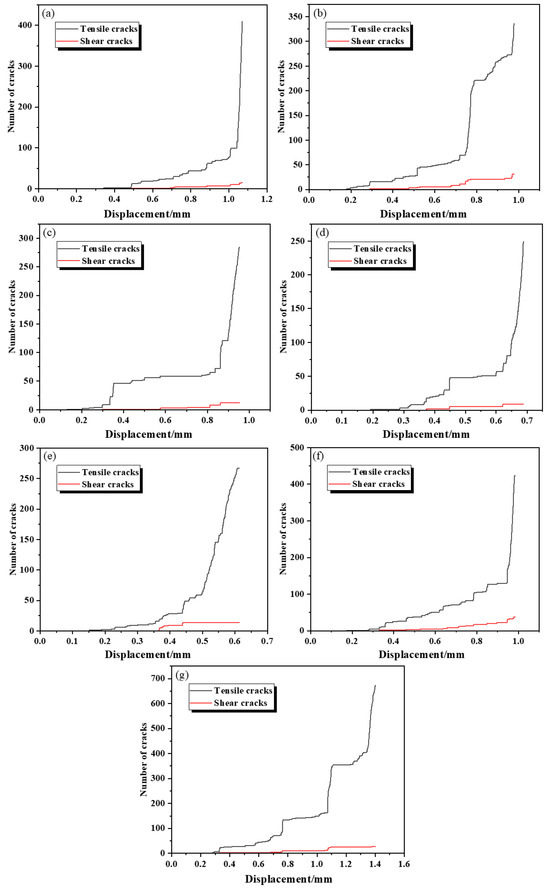
Figure 11.
The variation law of crack count with displacement. (a) Scheme A, (b) Scheme B1, (c) Scheme B2, (d) Scheme B3, (e) Scheme C1, (f) Scheme C2, and (g) Scheme C3.
For mixed-blend schemes (C1–C3), tensile failure counts are 267, 422, and 672, respectively, indicating that higher fiber content in mixed-blend schemes requires more energy for failure, consistent with the test results that mixed-blend fibers increase concrete strength with content.
5. Fracture Mechanisms of the Basalt Fiber Concrete Specimens
5.1. Influence Mechanism of Basalt Fibers on Splitting Failure of Specimens
Figure 12 presents the maximum tensile stress distribution laws of Scheme A and Scheme B1. By comparing the maximum principal stress distribution of Scheme A (blank control group) and Scheme B1 (single addition of 18 mm fiber, 0.1% dosage) in Figure 9, it can be seen that the addition of basalt fiber significantly alters the splitting and tensile failure mechanism of concrete by regulating the stress concentration mode. In Scheme A, the tensile stress concentration is mainly concentrated at the loading point and the middle of the concrete. Therefore, the cracks in the test arise from the loading end and pass through the specimen. In Scheme B1, the addition of 18 mm fibers introduces new stress concentration points within the concrete; local stress concentration occurs due to the difference in elastic modulus. This “stress transfer” effect stems from the bridging effect of the fibers. When the specimen is subjected to split tensile load, the fibers bear the tensile stress through the bonding force with the matrix, dispersing the stress originally concentrated at the matrix defects to the fiber–matrix interface. At this point, the fibers act as “stress buffers”, delaying the initiation and propagation of microcracks in the matrix. From the perspective of the failure mode, Scheme A directly leads to the rapid penetration of the main crack due to stress concentration, while the crack propagation of Scheme B1 presents a tortuous path due to fiber obstruction. When the final failure occurs, the fiber pulsation consumes more fracture energy, increasing the splitting tensile strength by 10.8% compared to Scheme A. This mechanism verifies that basalt fibers optimize the tensile performance of concrete by regulating the location and strength of stress concentration; that is, through the local stress concentration at the fiber, the uniformity of the overall stress distribution of the matrix is achieved, thereby suppressing brittle failure and enhancing the ductility of the material.
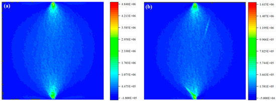
Figure 12.
The influence mechanism of basalt fiber on the splitting failure of specimens. (a) The maximum principal stress distribution of Scheme A; (b) maximum principal stress distribution in Scheme B1.
5.2. Influence Mechanism of Different Basalt Fiber Contents on Splitting Failure of Specimens
Figure 13 presents the maximum tensile stress distribution laws of Scheme B1 and Scheme B3. By comparing the maximum principal stress distribution of Scheme B1 (0.1% dosage) and Scheme B3 (0.3% dosage) in Figure 10, it can be seen that the change in basalt fiber content significantly affects the energy consumption mechanism of splitting tensile failure of concrete by regulating the stress concentration degree and bridging effect at the fiber–matrix interface. In Scheme B1, the low-content fibers (0.1%) are discretely distributed in the concrete, and the stress concentration areas at the fiber ends are relatively isolated. The bridging effect is mainly manifested as locally hindering the propagation of microcracks. At this time, the breaking energy consumed by fiber pulsation is limited, and the splitting tensile strength of the specimens is increased by 10.8% compared with the blank group. In Scheme B3, the fiber content is increased to 0.3%. The stress concentration regions of adjacent fibers overlap due to the reduced spacing, forming continuous high-stress zones. This dense stress concentration network significantly enhances the fiber bridging effect, which is manifested as the need to overcome more bonding resistance at the fiber–matrix interface during crack propagation.
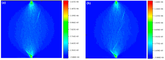
Figure 13.
The influence mechanism of different basalt fiber contents on the splitting and tensile failure of specimens. (a) The maximum principal stress distribution of Scheme B1; (b) the maximum principal stress distribution of Scheme B3.
5.3. Influence Mechanism of Single-Blend and Mixed-Blend on Splitting Failure of Specimens
Figure 14 presents the distribution laws of the maximum tensile stress of Scheme B3 and Scheme C3. By comparing the maximum principal stress distribution of Scheme B3 (single addition of 18 mm fiber, 0.3% addition) and Scheme C3 (mixed addition of 6 mm:12 mm:18 mm fiber, 0.3% addition) in Figure 11, it can be seen that the mixed addition scheme significantly expands the spatial distribution range of stress concentration by constructing a multi-scale fiber network, forming a gradient crack-blocking effect. In Scheme B3, the stress concentration area of single-doped 18 mm fibers is mainly distributed along the axial direction of the fibers, but the distribution of the high-stress area is relatively limited, resulting in cracks easily breaking through the fiber bridging in a single direction. In Scheme C3, due to the synergistic effect of fibers of different lengths, the stress concentration area extends from the fiber ends to the entire fiber network. The stress concentration value near the short fibers (6 mm) reaches 1.173 × 10⁶ Pa, and the high-stress zones formed by the medium and long fibers (12 mm, 18 mm) interweave with each other, forming a three-dimensional stress buffer system.
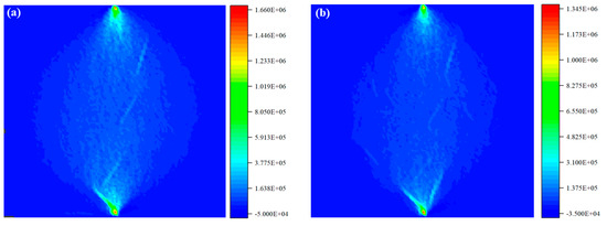
Figure 14.
The influence mechanism of single admixture and mixed admixture on the splitting and tensile failure of specimens. (a) The maximum principal stress distribution of Scheme B3; (b) the maximum principal stress distribution of Scheme C3.
6. Conclusions
- (1)
- Concrete split tensile tests were carried out with different basalt admixtures and under single and mixed admixtures. The fracture morphology of concrete specimens was obtained. The fracture process of basalt fiber concrete was simulated based on DEM, the test law was verified, and the fracture mechanism of basalt fiber concrete specimens was discussed.
- (2)
- The dosage of basalt fiber significantly affects the splitting tensile strength of concrete. When 18 mm fiber is added alone, a dosage of 0.2% is the optimal, and the strength is 10.8% higher than that of the blank group. Excessive (0.3%) leads to a 7.8% reduction in strength due to the decrease in dispersibility.
- (3)
- When 6 mm:12 mm:18 mm are mixed in a ratio of 3:4:3, multi-scale fibers form a three-dimensional crack-blocking network. Under the same dosage, the strength increase amplitude is 7.43% higher than that of the single-dosage group.
- (4)
- Fibers delay crack propagation through the stress concentration transfer mechanism. The single addition of fibers makes the crack path tortuous, while the mixed addition of fibers forms a bifurcated fracture network. When failure occurs, the energy consumption mode changes from single extraction to multi-level consumption.
- (5)
- The findings hold substantial practical implications for engineering applications in structures prone to tensile cracking, such as bridge decks, tunnel linings, and hydraulic channels. For bridge decks subjected to repeated traffic loads and temperature variations, the optimal 0.2% single-blend 18 mm fibers or 0.2% mixed-blend (6 mm:12 mm:18 mm = 3:4:3) scheme can enhance tensile resistance and delay fatigue crack initiation, extending service life by mitigating stress concentration at deck joints. In tunnel linings exposed to geostatic pressure and groundwater erosion, the mixed-blend fiber strategy, with its three-dimensional crack-blocking network, can reduce the risk of radial crack propagation induced by uneven rock pressure, improving durability against chemical ingress. These results support the revision of design standards by recommending 0.2% as the critical dosage threshold for basalt fiber-reinforced concrete in tensile-sensitive components, while advocating mixed-blend schemes in high-risk cracking zones. For construction practices, this study highlights the importance of fiber dispersion control—particularly avoiding excessive 0.3% content—and provides a basis for optimizing mixing protocols (e.g., extended dry-mixing time for higher dosages) to ensure uniform fiber distribution, thereby translating material performance gains into reliable structural anti-cracking capacity.
Author Contributions
Conceptualization, L.J.; Methodology, L.J. and S.Z.; Investigation, C.Z., S.Z., M.Q., R.Z., Y.L., W.Z. and S.Y.; Writing—original draft, L.J., C.Z., S.Z., M.Q., R.Z., Y.L., W.Z. and S.Y.; Writing—review & editing, L.J., C.Z. and S.Y.; Supervision, S.Z. and S.Y. All authors have read and agreed to the published version of the manuscript.
Funding
This work was supported by the Basic Scientific Research Business Expenses Project of Sichuan Provincial Scientific Research Institutes of China (2025-SKY-ZXKY-02).
Data Availability Statement
The original contributions presented in the study are included in the article, further inquiries can be directed to the corresponding authors.
Conflicts of Interest
The authors declare no conflict of interest.
References
- Xiao, J.; Shuai, J.; Deng, W.; Liu, L.; Wang, P.; Li, L. Low-Carbon and Green Materials in Construction: Latest Advances and Prospects. Buildings 2025, 15, 1508. [Google Scholar] [CrossRef]
- Weng, R.; He, Z.; Liu, J.; Lei, B.; Huang, L.; Xu, J.; Liu, L.; Xiao, J. Shear Performance of UHPC-NC Composite Structure Interface Treated with Retarder: Quantification by Fractal Dimension and Optimization of Process Parameters. Buildings 2025, 15, 2591. [Google Scholar] [CrossRef]
- Xiao, J.; Huang, L.; Weng, R.; Murong, Y.; Liu, L.; Zeng, H.; Jiang, H. Mechanism of chloride ion transport and associated damage in ultra-high-performance concrete subjected to hydrostatic pressure. J. Build. Eng. 2025, 113700. [Google Scholar] [CrossRef]
- Chen, L.; Li, S.; She, Z. A study on the impact of artificial intelligence applications on corporate green technological innovation: A mechanism analysis from multiple perspectives. Int. Rev. Econ. Financ. 2025, 103, 104490. [Google Scholar] [CrossRef]
- Pei, Y.; Chen, F. Real-Time Water Content Regulation in PEMFC Shutdown via MPC with SH-AUKF-Based State Feedback: Towards Improved Efficiency and Reduced Energy Consumption. eTransportation 2025, 100461. [Google Scholar] [CrossRef]
- Hao, H.; Yao, E.; Pan, L.; Chen, R.; Wang, Y.; Xiao, H. Exploring heterogeneous drivers and barriers in MaaS bundle subscriptions based on the willingness to shift to MaaS in one-trip scenarios. Transport. Res. A 2025, 199, 104525. [Google Scholar] [CrossRef]
- Yang, L.; Xie, H.; Fang, S.; Huang, C.; Yang, A.; Chao, Y.J. Experimental study on mechanical properties and damage mechanism of basalt fiber reinforced concrete under uniaxial compression. Structures 2021, 31, 330–340. [Google Scholar] [CrossRef]
- Shao, W.; Cao, R.; Zhang, W.; Shi, D. Experimental study on the compressive mechanical behavior and constitutive model of basalt fiber reinforced coral concrete. Constr. Build. Mater. 2025, 489, 142284. [Google Scholar] [CrossRef]
- Liu, Y.; Liu, H.; Liu, G.; Wang, W.; Zhong, Y.; Bao, J. Experimental and data-driven analysis on shear behavior of basalt fiber reinforced concrete deep beams with BFRP bars. Structures 2025, 78, 109197. [Google Scholar] [CrossRef]
- Xie, L.; Sun, X.; Yu, Z.; Guan, Z.; Long, A.; Lian, H.; Lian, Y. Experimental study and theoretical analysis on dynamic mechanical properties of basalt fiber reinforced concrete. J. Build. Eng. 2022, 62, 105334. [Google Scholar] [CrossRef]
- Xiao, J.; Zhou, Y.; Deng, Z.; Yang, H.; Mei, J.; Jiang, J.; Wei, T. Investigation of biaxial compressive mechanical properties and strength criteria of basalt fiber-reinforced coral aggregate concrete. Constr. Build. Mater. 2025, 475, 141199. [Google Scholar] [CrossRef]
- Niu, D.; Su, L.; Luo, Y.; Huang, D.; Luo, D. Experimental study on mechanical properties and durability of basalt fiber reinforced coral aggregate concrete. Constr. Build. Mater. 2020, 237, 117628. [Google Scholar] [CrossRef]
- Guo, T.; Liu, K.; Wang, H.; Si, X.; Rui, Y.; Pu, C.; Zhang, Y.; Yuan, C. Mechanical characteristics and fracturing behavior of rock-concrete composite specimens with two pre-existing parallel flaws under uniaxial compression based on AE and DIC systems. Theor. Appl. Fract. Mech. 2025, 136, 104866. [Google Scholar] [CrossRef]
- Wang, B.; Zhuang, N.; Nasr, A.A.; Chen, S.; Zhang, Y.; Jin, F. Experimental and theoretical validation of a prediction model for self-compacting concrete filling performance in rock skeletons. J. Build. Eng. 2025, 111, 113114. [Google Scholar] [CrossRef]
- Xu, W.; Fu, J.; Hua, R.; Han, F. ITZ volume fraction and thermal conductivity of concrete: A unified random packing model for gravels and crushed rocks. J. Build. Eng. 2024, 90, 109457. [Google Scholar] [CrossRef]
- Ince, R. Using SCB specimens to quantify nonlinear fracture characteristics in concrete and rock materials. Eng. Fract. Mech. 2025, 318, 110951. [Google Scholar] [CrossRef]
- Wang, H.; Jia, M.; Yang, X.; Wang, Y.; Yu, R.C. Determination of fracture toughness of concrete based on actual critical crack length: Theoretical model and experimental validation. Eng. Fract. Mech. 2025, 318, 110966. [Google Scholar] [CrossRef]
- Zhang, M.; Yu, H.; Zhang, J.; Chen, B.; Ma, H.; Gong, X.; Guo, J.; Yu, W.; Li, L. Finite element analysis of stress–strain relationship and failure pattern of concrete under uniaxial compression considering freeze–thaw action. Eng. Fract. Mech. 2023, 290, 109520. [Google Scholar] [CrossRef]
- Zhang, W.; Wang, H.; Zheng, J.; Wu, Z. Finite element simulation of mixed-mode I-II dynamic fracture of concrete based on an initial fracture toughness-based criterion. Eng. Fract. Mech. 2024, 298, 109926. [Google Scholar] [CrossRef]
- Huang, C.; Wang, Z.; Li, S.; Chen, Y.; Dai, M.; Wu, W.; Wei, W.; Gao, J.; Yang, Q. Coupling algorithm of cavity expansion theory and finite element for penetrating reinforced concrete. Eng. Fract. Mech. 2024, 311, 110580. [Google Scholar] [CrossRef]
- Liang, G.; Liu, T.; Chen, Z.; Xia, Y. Peridynamics-coupled finite element method implication in concrete material crack prediction. Eng. Fract. Mech. 2024, 312, 110615. [Google Scholar] [CrossRef]
- Haghani, M.; Navayi Neya, B.; Ahmadi, M.T.; Vaseghi Amiri, J. A new numerical approach in the seismic failure analysis of concrete gravity dams using extended finite element method. Eng. Fail. Anal. 2022, 132, 105835. [Google Scholar] [CrossRef]
- Faron, A.; Rombach, G.A. Simulation of crack growth in reinforced concrete beams using extended finite element method. Eng. Fail. Anal. 2020, 116, 104698. [Google Scholar] [CrossRef]
- Aghajanzadeh, S.M.; Mirzabozorg, H. Concrete fracture process modeling by combination of extended finite element method and smeared crack approach. Theor. Appl. Fract. Mech. 2019, 101, 306–319. [Google Scholar] [CrossRef]
- Benvenuti, E.; Orlando, N. Intermediate flexural detachment in FRP-plated concrete beams through a 3D mechanism-based regularized eXtended Finite Element Method. Compos. Part B 2018, 145, 281–293. [Google Scholar] [CrossRef]
- Li, F.; Feng, J.L.; Chen, X. Modeling of the fracture behaviors of concrete using 3D discrete element method with softening effect. Theor. Appl. Fract. Mech. 2024, 133, 104597. [Google Scholar] [CrossRef]
- Peng, Z.; Liu, Q.F.; Gao, X.; Zhao, X.Y.; Xia, J.; Xiong, Q.X. Effects of aggregate distribution on the cracking behavior of concrete: A discrete element method study. Cem. Concr. Compos. 2025, 162, 106119. [Google Scholar] [CrossRef]
- Knak, M.; Nitka, M.; Rucka, M. Discrete element method modelling of elastic wave propagation in a meso-scale model of concrete. Ultrasonics 2024, 141, 107336. [Google Scholar] [CrossRef]
- Yu, J.; Zhang, B.; Zhao, J. An improved model for discrete element method simulation of spatial gradient distributions of freeze-thaw-induced damage to sandstone. Comput. Geotech. 2024, 171, 106412. [Google Scholar] [CrossRef]
- Wang, X.; Li, J.; Zhao, X.; Liang, Y. Propagation characteristics and prediction of blast-induced vibration on closely spaced rock tunnels. Tunn. Undergr. Space Technol. 2022, 123, 104416. [Google Scholar] [CrossRef]
- Xiao, W. Analytical theory on instability sliding of surrounding rock blocks in tunnel roof under stress wave actions. Chin. J. Theor. Appl. Mech. 2024, 56, 183–197. [Google Scholar]
- Sun, L.; Shi, W.; Tian, X.; Li, J.; Zhao, B.; Wang, S.; Tan, J. A plane stress measurement method for CFRP material based on array LCR waves. NDT E Int. 2025, 151, 103316. [Google Scholar] [CrossRef]
- Wang, X.; Zhang, X.; Li, W.; Jiang, Y.; Li, Z.; Wang, C. Analytical theoretical study on ultra-low friction characteristics of coal rock interfaces under stress wave action. J. China Coal Soc. 2024, 49, 4495–4507. [Google Scholar]
Disclaimer/Publisher’s Note: The statements, opinions and data contained in all publications are solely those of the individual author(s) and contributor(s) and not of MDPI and/or the editor(s). MDPI and/or the editor(s) disclaim responsibility for any injury to people or property resulting from any ideas, methods, instructions or products referred to in the content. |
© 2025 by the authors. Licensee MDPI, Basel, Switzerland. This article is an open access article distributed under the terms and conditions of the Creative Commons Attribution (CC BY) license (https://creativecommons.org/licenses/by/4.0/).