Abstract
Steel reinforced grout (SRG) composites are widely used for strengthening existing structures. Galvanized (zinc-coated) ultra-high tensile strength steel cords are more durable than brass-coated and cheaper than stainless-steel ones, making them the most common in practice. While compliant with certification standards, corrosion may occur, potentially affecting tensile strength and bond capacity. The latter has, however, remained largely unexplored, highlighting a need to assess durability under different environmental exposures. This study investigated the durability of galvanized SRGs with four cord types and four mortar matrices (cement- and lime-based). Direct tensile, shear bond, and lap-tensile tests were conducted after immersion in saltwater or alkaline solutions, exposure to freeze–thaw or salt crystallization cycles, and high temperatures. Results highlighted salt exposure as the most critical condition, particularly with lime-based matrices. Zinc coating thickness proved essential for corrosion resistance, while freeze–thaw and salt crystallization led to bond degradation due to concentrated steel corrosion and mortar microcracking. The findings highlight the importance of considering appropriate protective measures and exposure-specific conditions when designing SRG reinforcements.
1. Introduction
Steel reinforced grout (SRG) is a composite system comprising steel micro-cords embedded in a mortar matrix, widely used for the repair and strengthening of existing concrete and masonry constructions [1]. It was developed from the brilliant idea of using ultra-high tensile strength steel (UHTSS) cords, originally designed for automobile tyres, in externally bonded reinforcements [2,3,4]. This system can be seen as an evolution of ferrocement, patented by Pier Luigi Nervi in 1943 [5], as both involve small-diameter metallic wires embedded in thin cementitious layers. Nonetheless, ferrocement was conceived for new, self-bearing structures, such as slender shells with architectural value, while SRG is designed as an externally bonded reinforcement for existing structures. It fits more appropriately within the category of inorganic matrix composites, such as fabric reinforced cementitious matrix (FRCM) systems, which include carbon, glass, basalt, aramid, and PBO meshes.
SRG and FRCM share several advantages—high strength-to-weight ratio, ease of installation, good performance at high temperatures [6], and compatibility with historic substrates (when using lime-based mortars). They also follow similar certification and design guidelines in both Europe and the US [7,8,9,10].
Initially, however, their recognition as equivalent systems developed slowly, partly due to their origins in the fibre-reinforced polymers (FRPs) research community. For instance, ACI 549.4R-13 only considered carbon and glass FRCM, while SRG appeared in the updated ACI 549.6R-20 [7]. Similarly, the first Italian FRP certification standard (2015) did not include steel reinforced polymers (SRPs), which were later added in the 2019 version [11]. Today, both FRCM and SRG are regulated under similar frameworks (e.g., EAD [10], AC434 [9], CSLLPP [8,12]), and are used across a wide range of structural rehabilitation applications.
Although often grouped under the FRCM acronym, SRG and FRCM still present differences. SRG cords, made of ultra-high tensile strength steel (UHTSS) micro-wires (0.2–0.5 mm), are thicker than fibres in typical FRCM meshes, which are usually bidirectional, unlike steel textiles’ unidirectional configuration. Furthermore, durability mechanisms differ: SRG may corrode under salt attack, whereas FRCM meshes exhibit deterioration in alkaline (glass, basalt, aramid) [13] or a UV-exposed (carbon, PBO) environment.
SRG cords have excellent tensile strength (3000–3200 N/mm2), Young’s modulus (170–190 kN/mm2), and ultimate strain (2.0–2.2%), and their roughness provides effective interlocking with the matrix, leading to high SRG-to-substrate load transfer capacity (130 kN/m and 220 kN/m) [14,15,16,17,18,19]. Nonetheless, an appropriate coating should be applied to the steel wires to prevent their deterioration and preserve mechanical performance in aggressive environments.
Steel corrosion issues have driven advancements in SRG development. Early use of brass-coated cords proved ineffective [20], with tensile tests showing significantly better durability in galvanized (zinc-coated) cords after natural and artificial aging. For instance, exposure to 5%wt NaCl saline mist (pH 6.5–7.2) at 35 °C [21], for 1, 2, or 4 weeks, led to a 9–17% strength loss in brass-coated cords versus 2–5% in galvanized ones. SRG composites exhibited greater deterioration than bare textiles, likely due to the alkaline environment of the matrix.
The tensile performance of galvanized UHTSS textiles after up to 3000 h in substitute ocean water [22] confirmed the resistance of zinc coating to salt-induced corrosion, even after bending [23]. Strength and stiffness losses remained below 7%, well within certification limits (15% after 1000 h, 20% after 3000 h) [12].
Tensile tests on SRG composites with cement mortar aged for 1000 h in substitute ocean water by Signorini and Nobili [24] revealed a greater strength loss for galvanized textiles (~36%) compared to brass-coated ones (17%), highlighting the non-negligible role of the matrix in steel cord deterioration. This suggests that aging bare cords may underestimate degradation and explains why galvanized textiles have replaced brass-coated ones in research and practice.
The load transfer capacity with the substrate is crucial for externally bonded reinforcements, yet bond durability has been less studied due to the complexity, cost, and time required for bond tests. Consequently, most certification guidelines [9,12] rely on tensile tests after aging in substitute ocean water, alkaline solutions, high humidity, and freeze–thaw cycles. The direct investigation of bond durability is avoided in Italian national standards, but the possibility of extending the results of tensile tests to bond mechanisms remains uncertain. Only EU standards [10] include bond tests on aged specimens, after exposure to humidity or full immersion in saline or alkaline solutions. However, full immersion may not represent the most severe condition, as wetting–drying cycles can cause salt crystallization and oxidation processes. Freeze–thaw cycles, on the other hand, are not contemplated.
Franzoni et al. [25,26] conducted ground-breaking research on SRG-to-masonry bond durability by cyclically immersing in 8%wt Na2SO4·10H2O solution or deionized water until complete saturation, followed by oven drying to promote salt crystallization. Both lime and cement mortars were tested to evaluate matrix porosity effects on solution capillary flow and salt deposition. Load transfer capacity decreased by 12–23%, depending on solution (saline/water), number of cycles (4/6), and matrix type (lime/cement). Deterioration was attributed to cord corrosion, where rust was observed, causing failure at the textile-to-matrix interface, while matrix properties and matrix-to-substrate interface remained unaffected. No salt accumulation was found in mortar pores. Corrosion in SRG bonded to aged substrates indicated salt migration from substrate to cords during curing.
These results served as a wake-up call, promoting interest in stainless-steel cords, previously sidelined due to lower tensile strength (1600–2000 N/mm2) and higher cost. Following preliminary studies on prototypes [15,27], recent research has focused on the mechanical characterization and durability of stainless-steel reinforced grout (SSRG) [28], and its practical applications [29]. SSRG composites exhibited excellent tensile performance after multiple aging conditions—even beyond certification durations—despite the use of a lime-based matrix (negligible strength loss after freeze–thaw cycles and thermal stress, and aging in humidity, alkali and salt attack for up to 5000 h).
Undoubtedly, SSRG has so far gained limited market share in structural rehabilitation, where galvanized SRG still dominates. Its advantages—tensile strength, bond capacity—are well established. However, the literature review highlights potential concerns regarding the long-term behaviour of galvanized SRG. To ensure its safe and effective use, improved knowledge is needed on the following:
- the minimum zinc coating thickness, a critical yet unexplored factor in textile durability, for which clear design and certification guidelines should be defined;
- the influence of matrix type (lime-based or cement-based) on SRG durability, in relation to their chemical composition, porosity, and cracking behaviour;
- the long-term bond durability, essential for externally bonded systems but often overlooked in current certification protocols;
- the impact of wetting–drying cycles, which may promote salt crystallization and better reflect in-service exposure conditions than full immersion tests currently prescribed by most codes.
This paper presents a laboratory investigation on the decay of the mechanical performance of galvanized SRG composites under aging processes. Four textiles made of galvanized UHTSS cords were tested in combination with two lime mortars (one fibre-reinforced) and two cement mortars (one fibre-reinforced). Direct tensile tests on bare textiles and SRG composites were performed after aging in saltwater, alkaline solutions, freeze–thaw cycles and high temperatures. The influence of the mortar type [30,31] and cord spacing [32] was assessed in relation to the ability to protect the steel cords and ensure proper adhesion with both textile and substrate. The role of zinc coating thickness, crucial for corrosion protection [33,34], largely unaddressed in the literature and not even covered in recent reviews [35], was also investigated. Bond tests on concrete and masonry substrates were carried out after freeze–thaw cycles, wetting–drying in water and saltwater, and full immersion in saltwater. Degradation effects on bond performance were analysed, with particular attention to salt-crystallization cycles, still poorly understood despite their practical relevance. Lap-tensile tests were also performed to study the impact of aging (full immersion in water, saltwater, and alkaline solution) on stress-transfer mechanisms in textile overlaps. Aging protocols followed both certification standards [10] and literature-reported aggressive scenarios [26]. Test outcomes highlight the beneficial performance of galvanized SRGs and identify critical aspects needing further investigation, including protective strategies for long-term durability.
This paper is an extended version of a conference contribution (Insight on the Durability of Steel Reinforced Grout (SRG) Systems for the Strengthening of Historical Constructions [36], presented at 5th International Conference on Protection of Historical Constructions—PROHITECH 2025, Naples (Italy) 26–28 March 2025), with additional discussion of tensile data and a comprehensive experimental programme on bond and lap-tensile behaviour after aging. The conclusions benefit from this broader dataset, offering insights across different mechanical tests.
2. Experimental Programme, Materials and Aging Processes
2.1. Experimental Programme
With the aim of deepening knowledge on the durability of galvanized SRG composites, a wide-ranging experimental campaign was conducted. Four unidirectional steel textiles were selected (labelled G1 to G4), differing in cord architecture, surface mass density, and thickness of the protective zinc coating (§2.2). The textiles were combined with four mortars: two lime mortars (L1 and L2) and two cement mortars (C1 and C2) (§2.2), with L2 and C2 being fibre reinforced. G1 and G2 textiles were combined with L1 and C1 mortars, while G3 and G4 were used in composites with L2 and C2. In total, eight SRG systems were tested—four with lime mortar and four with cement mortar.
Test programmes comprised the following tests:
- Direct tensile tests on bare textiles, both straight and bent (§3);
- Direct tensile tests on SRG composites (§3);
- Single-lap shear bond tests, on concrete and brick masonry substrates (§4);
- Lap-tensile tests on SRG composites (§5).
The following aging processes were considered:
- Dry heat;
- Thermal stress;
- Freezing and thawing;
- Water, both total immersion and wetting–drying cycles;
- Saltwater, both total immersion and wetting–drying cycles;
- Burying in alkali soil;
- Alkaline solution.
Finally, multiple aging durations were considered, i.e., 20, 40 cycles and 1000, 3000 h (§2.3).
Figure 1, and Table 1 and Table 2 summarize the experimental programme. Tests were labelled as JJ-KK-WWXX-YYZ, where
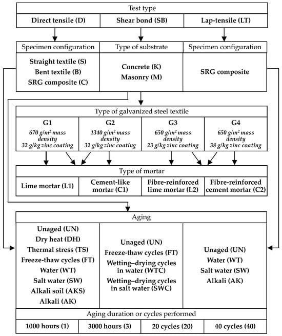
Figure 1.
Experimental programme: test matrix and specimen labelling.

Table 1.
Test matrix of direct tensile test.

Table 2.
Test matrix of shear bond test and lap-tensile test.
- JJ identifies the type of test: DS for direct tensile on straight textile, DB for direct tensile on bent textile, DC for direct tensile on SRG composite specimen, SB for single-lap shear bond and LT for lap-tensile tests;
- KK refers to the type of substrate (for shear bond tests only): K for concrete and M for brick masonry;
- WW identifies the type of textile: G1, G2, G3 or G4;
- XX identifies the type of mortar: L1 for lime mortar, L2 for fibre-reinforced lime mortar, C1 for cement mortar and C2 for fibre-reinforced cement mortar;
- YY identifies the aging: UN for unaged, DH for dry heat, TS for thermal stress, FT for freeze–thaw cycles, WT for water immersion, WTC for wetting–drying cycles in water, SW for saltwater immersion, SWC for wetting–drying cycles in saltwater, AKS for alkali soil environment, AK for immersion in alkaline solution;
- Z is the aging duration in thousands of hours (1 and 3, for 1000 and 3000 h) or in cycles performed (20 and 40, for 20 cycles and 40 cycles).
2.2. Materials
The four textiles considered in the study are listed below. All are unidirectional and made of ultra-high tensile strength carbon steel cords, selected among the most commonly used for SRGs in the market and in situ applications, based on cord type, steel type, and coating technology.
- G1: this textile has a surface mass density of 670 g/m2, a design thickness of 0.084 mm and a spacing between cords of 6.35 mm (0.157 cords/mm) (Figure 2a). The cord has a cross-sectional area of 0.538 mm2 and is composed of five steel micro-filaments (3 straight and 2 twisted, each 0.37 mm in diameter), which are galvanized (zinc-coated) to protect against rust. The zinc coating averages 32 g/kg of steel. To facilitate handling and installation, steel cords are thermo-welded to a fiberglass mesh, which does not contribute to the textile’s strength or stiffness.
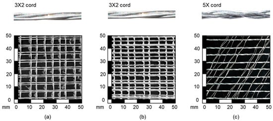 Figure 2. Types of galvanized steel textile used: (a) G1, (b) G2 and (c) G3, G4.
 - G2: this textile has a surface mass density of 1340 g/m2, a design thickness of 0.0169 mm, and a cord spacing of 3.18 mm (0.314 cords/mm) (Figure 2b). The cords’ characteristics, including the zinc coating, are the same as G1. Similarly, the textile is equipped with a fiberglass mesh.
- G3: this textile has a surface mass density of 650 g/m2, a design thickness of 0.083 mm, and cord spacing of 6.40 mm (0.156 cords/mm) (Figure 2c). The cords have a cross-sectional area of 0.53 mm2 and are made of five twisted electro-galvanized steel wires, each 0.33 mm in diameter. The mass of the zinc coating amounts at 23 g/kg. Unlike G1 and G2, to facilitate installation, the textile is equipped with transversal micro steel wires of small cross-section, whose strength is negligible.
- G4: this textile has the same characteristics of G3 (Figure 2c), except for the protective zinc coating, which in this case was obtained by hot dip galvanization, with a higher mass of 38 g/kg.
Regarding the matrices, the following mortars were used:
- L1: lime mortar, classified in M15 strength class [37], with compressive strength fcm = 16.9 N/mm2 and Young’s modulus Ecm = 5.8 kN/mm2 (average values evaluated through compression tests on 12 40 mm × 40 mm × 40 mm specimens, according to [30,31]), and tensile strength ftm = 4.5 N/mm2 (average value from bending tests on 6 40 mm × 40 mm × 160 mm prisms, according to [37,38]). The mortar comprises natural hydraulic lime (NHL) and a geopolymeric binder, 0.1–1 mm siliceous sand, 0–1.4 mm limestone and 0–0.2 mm pure fine marble.
- L2: fibre-reinforced lime mortar, classified in M15 strength class [37], with fcm = 23.4 N/mm2, Ecm = 4.8 kN/mm2 (12 tests) and ftm = 4.7 N/mm2 (6 tests). The mortar is based on fibre-reinforced NHL with a maximum aggregate grain size of 1.2 mm and a geopolymer-based binder with an organic content of no more than 1%.
- C1: thixotropic cement-like mortar, classified in M25 strength class [37], having fcm = 86.7 N/mm2, Ecm = 13.5 kN/mm2 (12 tests) and ftm = 7.8 N/mm2 (6 tests). It is a geopolymeric mortar with a maximum aggregate grain size of 0.5 mm.
- C2: fibre-reinforced thixotropic cement mortar, classified in M25 strength class [37], with fcm = 69.0 N/mm2, Ecm = 11.8 kN/mm2 (12 tests) and ftm = 9.0 N/mm2 (6 tests). The mortar is enriched with fibres and has a maximum aggregate grain size of 0.5 mm.
2.3. Aging Processes
The following aging processes were carried out, according to [10,12]:
- Dry heat (DH). According to [39], specimens were exposed to a temperature of 70 °C, for an exposure time of 1000 and 3000 h.
- Thermal stress (TS). The specimens were exposed for 6 h at a temperature of 60 °C before testing. Then, they were tested at the same temperature by means of a climatic chamber installed on the testing machine.
- Freeze and thaw (FT). The specimens were exposed to a relative humidity (RH) of 95% and a temperature of 38 °C for one week, followed by 20 or 40 freeze–thaw cycles, each comprising 4 h at −18 °C and 12 h at 38 °C and RH = 95%.
- Water (WT). The specimens were exposed to a temperature of 38 °C and a RH = 95% for 1000 and 3000 h, according to [40,41].
- Saltwater (SW). The specimens were immersed in a saline solution at a temperature of 23 °C, for 1000 and 3000 h. The solution was prepared according to [22]; “Sea Salt” from Lake Products Company LLC was used, with a proportion of 41.953 g salt for 1 litre of distilled water.
- Alkali soil (AKS). The specimens were buried in a 6.5–7.5 pH soil, in vertical position, at a depth of 125 mm for 1000 h. The soil containers were stored in a room at a temperature of 32–38 °C.
- Alkali (AK). The specimens were immersed in an alkaline solution at a temperature of 23 °C, for 1000 and 3000 h. The solution was prepared in accordance with [42] by adding hydrated lime to distilled water in such a way as to have a pH > 9.5, which was weekly verified by means of a pH tester.
Two further aging processes, not suggested by standard codes, but already investigated in the literature [25,26], were considered for shear bond tests only:
- Wetting–drying cycles in water (WTC). The specimens were subjected to wetting and drying cycles in distilled water, for a total exposure time of 3000 h. Each cycle consisted of 4 days of immersion (wetting phase) and 3 days in a ventilated oven at a temperature of 40 °C (drying phase). A total of 18 cycles were performed. During immersion, specimens were laid horizontally in a water tank, with the water level at about half the height of the substrates to which SRGs were bonded. In this way, water reached the SRG by capillary rise. This was done to simulate a typical condition occurring in situ, in which the composite system comes into contact with water due to its permeation through the substrate. A silicon layer was applied to fully cover the sides of the substrate prism, except for the immersed side in contact with the tank and the bonded area, to promote capillary rise and concentration in this area.
- Cycles of salt crystallisation (SWC). The specimens were subjected to wetting and drying cycles (same mode as WTC) in “Sea Salt” solution [21] for 3000 h. Also, in this case, specimens were siliconized as specified above.
Wetting–drying cycles in a saline environment were expected to be more aggressive than continuous immersion in saltwater, due to the combination of physical and chemical phenomena that are activated during alternated environmental conditions [25,26]. During wetting, salts dissolved in the porous matrix crystallise, generating pressures that create microcracks in the mortar, especially if it is lime-based. These microcracks weaken cord-to-matrix adhesion and facilitate oxygen and chloride ions to penetrate, increasing localised corrosion. Furthermore, the alternation between saturated (wet) and aerated (dry) phases speeds up oxidation and prevents stable passivation of the zinc coating. Added to this is the increase in salt concentration in the pores during water evaporation, which intensifies local chemical aggression. These effects are amplified in systems with more porous mortars and in small-diameter cords, which offer a large attack surface. On the other hand, continuous immersion results in oxygen-poor conditions (almost anoxic), which tend to slow down electrochemical reactions, causing slower and more widespread corrosion.
2.4. Rationale of the Experimental Programme
As shown in Table 1, not all possible textile–mortar combinations were investigated, nor were all test types and conditioning processes carried out to each textile type or composite system. This was primarily due to the excessive time and cost that such a comprehensive program would have required, and also because it was deemed unnecessary to achieve the objectives of the study.
The logic behind the experimental programme is explained below, and will be further supported by the results discussed in §3-5:
- A single textile type, G3, was selected to be tested in the bent configuration, both in the unaged condition (UN) and after immersion in saltwater (SW). This choice was made with the sole objective to investigate the durability of the protective action of the zinc coating once its integrity had been affected by bending (§3.2.1).
- As for composite specimens, the coupling of textile and mortar was made considering the specifications provided in the technical data sheets of the materials, with the aim of testing systems that can be or are already applied in the field, thus maximising the significance of tests results.
- The G4 textile was excluded from the tensile tests of bare textiles and was tested only in the SRG composite configuration after immersion in saltwater. It was specifically selected to evaluate the effectiveness of increased zinc coating thickness in enhancing the SRG’s durability under highly aggressive conditions, i.e., composite in saltwater.
- The aging in an alkali soil environment was only carried out on SRG composites, consisting of G1 and G2 textiles and L1 and C1 matrices, to limit the burden of experimentation. This aging protocol followed the instructions of [10] and was carried out to simulate real exposure conditions for externally bonded reinforcements in contact with soil or masonry affected by rising damp, where moderate alkalinity, moisture, and oxygen coexist and may trigger degradation mechanisms.
- For the same reasons related to limiting the experimental workload, the durability against dry heat, thermal stress and conditioning in alkaline solution was investigated on a limited number of systems.
- Shear bond tests were carried out only on SRG systems made of G1 textile. The reasons for focusing on a single textile type relied on the cost inherent in this test and the similar surface mass density and cord spacing of G1 if compared to G3 and G4 textile, the latter being a parameter influencing the SRG-to-substrate bond [15]. Furthermore, for compatibility between the matrix and the substrate, the SRG system consisted of a lime-based mortar (L1) when bonded to masonry substrates and a cement-like mortar (C1) in the case of concrete substrates.
- To complete the investigation on the durability of the stress transfer mechanism, lap-tensile tests were carried out on SRG composite specimens made only with G2 textile, which had not been included in bond tests despite its smallest cord spacing. This configuration was considered critical due to the expected lower mechanical interlocking. Given its high density (small cord spacing), a bond test would likely have caused premature textile–matrix debonding. Therefore, the lap-tensile test (simpler and less demanding while investigating the same mechanism) was preferred to assess durability under unfavourable conditions.
3. Tensile Tests on Bare Textiles and SRG Composites
3.1. Experimental Setup
Bare textile and SRG composites were tested, according to [10,12], to characterize their tensile behaviour. The specimens had the following geometric characteristics:
- G1 textile strips consisted of 5 cords, corresponding to a cross-sectional area of 2.69 mm2, and had a length of 600 mm. The corresponding composite specimens were manufactured with textile strips of the same width had a total length of 400 mm, a width of 40 mm and a thickness of 10 mm.
- G2 textile strips comprised 10 cords, had 5.38 mm2 cross-sectional area and a length of 600 mm. The corresponding composites were 400 mm long, 40 mm wide and 10 mm thick.
- G3 and G4 textile strips consisted of 8 cords (4.25 mm2 cross-sectional area), and had a length of 460 mm. The corresponding composites had a total length of 460 mm, a width of 50 mm and a thickness of 10 mm.
Direct tensile tests were conducted in the direction parallel to the cords, under displacement control, at a rate of 0.5 mm/min, using a 100 kN capacity universal material testing system (MTS) machine (Figure 3). Specimens were clamped in the machine wedges, and, when necessary, a preload equal to 5% of the expected failure load was applied to align the specimen with the load axis and prevent bending. Load was applied by a hydraulic actuator and recorded via an integrated load cell at 10 Hz sampling rate. An MTS extensometer (base length of 50 mm for bare textiles and 200 mm for the SRG composites) was positioned centrally on the specimen after preload to measure strain (ε). The extensometer was removed at about 85% of the maximum expected load to avoid damage. Additional strain measurement was obtained through a linear variable differential transformer (LVDT) integrated in the machine, measuring relative displacement between clamping wedges. LVDT displacement was divided by the free length of the specimen (distance between wedges) and corrected using extensometer strain data. Stress (σ) was calculated as load divided by the textile cross-sectional area. To ensure uniform stress distribution at the load introduction areas, aluminium tabs were epoxy-glued at the edges of the bare textile before testing [43]. For composite specimens, ends were wrapped with two layers of glass fibre reinforced polymer (GFRP) over a length of 80 mm to ensure uniform stress distribution and prevent mortar splitting [43].
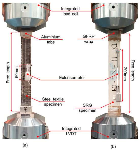
Figure 3.
Experimental set-up of direct tensile tests on (a) bare textile and (b) SRG composite specimens.
Tests on bent textiles were carried out with the same testing machine used for straight textiles and SRG composite specimens, at the same testing rate. The strips were bent in the middle forming the outline of an isosceles triangle with 50 mm sides, according to [12] (Figure 4a). A specifically designed device was used to bend the cords (Figure 4b). The bent strips were provided with the aluminium tabs (Figure 4c) and tested as described above.
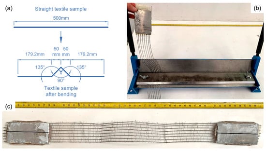
Figure 4.
Bending of steel textile: (a) bending procedure [12], (b) bending machine, (c) textile strip after bending.
3.2. Tests on Unaged Specimens
3.2.1. Bare Textile Specimens
The results of tensile tests on unaged textiles are collected in Table 3, for both the straight and the bent configurations. N = 20 specimens of G1 and G2 were tested (which corresponds to a fractile factor of kn = 1.76 according to Annex D of Eurocode 0 [44]), whereas for G3 N = 9 and kn = 2. Results are expressed in terms of average ultimate tensile (σf) and yield (σy) stress, evaluated according to [12], and of corresponding strain (εf) and coefficients of variation (CV_σf and CV_σy). Table 3 also lists the number of tests (N), the average value of the tensile modulus of elasticity (Ef) and the characteristic values (0.05-fractile) of σf and σy, which are named as σfk and σyk, respectively. Finally, for G3 textile in bent configuration, the percentage decrease in ultimate tensile stress (Δσf) and yield stress (Δσy) with respect to the straight configuration is also shown.

Table 3.
Results of direct tensile tests on bare textiles.
Figure 5 shows the stress–strain curve of each specimen. In addition, for an immediate visualisation of the overall tensile behaviour, the average curves are represented, which were derived by calculating the average stress values corresponding to the strain values of each curve. An almost linear behaviour was exhibited by straight textiles, with a progressive stiffness decrease at about 80% (for G1 and G2) and 50% (for G3) of the peak load, until failure (Figure 5a–c). Ef, σf and σy were equal to 190.6 kN/mm2 (CV = 14.46%), 3124.2 N/mm2 and 2526.1 N/mm2, and 184.4 kN/mm2 (CV = 12.08%) for G1, 3005.2 N/mm2 and 2470.6 N/mm2 for G2, and 182.9 kN/mm2 (CV = 3.90%), 2058.5 N/mm2 and 1679.8 N/mm2 for G3. All the textile types failed by the progressive rupture of the cords, at different sections along the free length of the specimen (Figure 6a). All wires in a cord broke simultaneously, but the failure was not synchronous in all the cords, resulting in the stress drops displayed in the plots after the peak (Figure 5a–c).

Figure 5.
Direct tensile tests on bare steel textiles (D)—tensile stress (σ) vs. strain (ε) response curves of unaged (UN) specimens: (a) G1, (b) G2, (c) G3 straight (S), and (d) G3 bent (B) configurations.
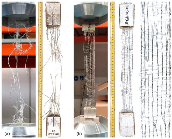
Figure 6.
Direct tensile tests on bare steel textiles—failure modes of unaged steel textiles in (a) straight configuration and (b) bent configuration.
The stress–strain curves for G3 bent specimens (Figure 5d) started from a preload of about 5% of the ultimate stress. This preload was necessary to tension the cords equally due to the looseness introduced by bending when the specimen was installed in the test machine. Results indicate that bending significantly affects the mechanical properties of unaged textiles. Specifically, the bent textiles exhibited a 14% reduction in stiffness compared to their straight counterparts. A Δσf = 23% decrease in peak stress was also observed. This reduction of both stiffness and strength suggests that the bending process introduces stress concentrations and localised damage or microstructural changes that reduce the material’s ability to resist deformation and tensile stress. The failure mechanism involved the progressive breaking of the wires within the cord, starting from the external ones, at the bent sections (Figure 6b). This progressive failure indicates that the external wires, which are subjected to the highest stress during bending, fail first, leading to a gradual failure of the entire cord. Finally, a Δσy = 11% decrease in yield stress was observed, indicating that bending causes a reduction in the material’s ability to withstand plastic deformation, likely due to the introduction of microstructural defects or residual stresses.
3.2.2. SRG Composite Specimens
Results of direct tensile tests on SRG composite specimens are collected in Table 4 and shown in Figure 7 and Figure 8, in terms of both stress–strain curves and failure modes. In addition to textile type (G1–G3), test code and number of specimens (N), Table 4 collects the average value of ultimate tensile stress (σu) and corresponding coefficient of variation (CV_σu) and tensile strain (εu), as well as the average tensile modulus of elasticity of the specimen in the uncracked (EI) and in the cracked (EIII) stages [10,12]. The characteristic (0.05-fractile) value of σu (σuk) is also listed. Note that stresses refer to the textile cross-section. N = 20 tests (kn = 1.76) were performed for the SRG composites comprising G1 and G2 textiles, whereas N = 14 (kn = 1.96) for SRG composites with G3.

Table 4.
Results of tensile tests of SRG composite specimens.
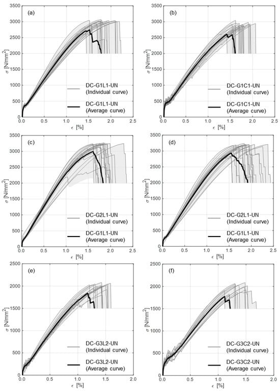
Figure 7.
Direct tensile tests on SRG composites (DC)—tensile stress (σ) vs. strain (ε) response curves of unaged (UN) specimens: (a) G1L1—steel textile G1 and lime mortar, (b) G1C1—steel textile G1 and thixotropic cement-like mortar, (c) G2L1—steel textile G1 and lime mortar, (d) G2C1—steel textile G2 and thixotropic cement-like mortar, (e) G3L2—steel textile G3 and fibre-reinforced lime mortar, (f) G3C2—steel textile G3 and fibre-reinforced thixotropic cement-like mortar.
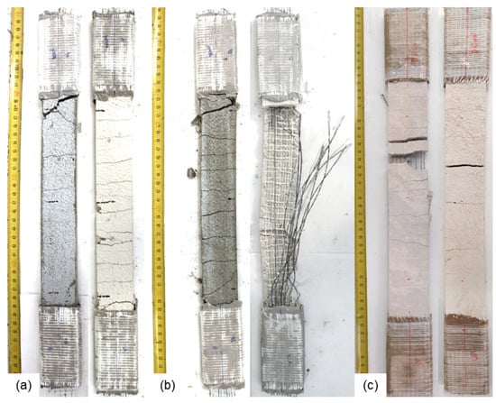
Figure 8.
Direct tensile tests on SRG composites—failure modes of unaged SRG composite specimens with (a) G1, (b) G2 and (c) G3 textiles (cement mortar at left and lime-based mortar at right).
The typical three-stage tensile behaviour of mortar-based composites was exhibited by the SRG composite specimens (Figure 7), characterised by a first linear stage in which the matrix is uncracked, a second stage with the progressive development of multiple cracks and a third, almost linear, stage, in which the specimen is completely cracked and its stiffness and strength depend mainly on the textile [45]. Cement-based SRG, compared to those with lime-based mortars, reached higher stresses in the second stage, with a more prolonged crack development phase. SRG systems with textiles with larger cord spacing (G1 and G3), attained higher values of the ultimate tensile stress (σu) with the lime mortar due to the better interlocking between mortar and textile, with respect to the ones with cement matrices. Conversely, when the textile had a smaller cord spacing (as in G2), the smaller grain size of the cement mortar led to a higher strength.
For G1 and G3-based SRGs, failure occurred by the simultaneous rupture of cords in correspondence of a cracked section, typically one of the first cracks developed in the mortar, due to stress concentration (Figure 7a,b,e,f and Figure 8a,c). The higher surface mass density of G2 textile prevented complete mortar penetration between cords, reducing the textile-to-mortar bond, thus not allowing a uniform stress distribution among cords. This led G2-based specimens to fail by the progressive tensile failure of cords (Figure 7c,d and Figure 8b).
3.3. Tests on Aged Specimens
3.3.1. Bare Textile Specimens
The results of tensile tests on G3 bare textile, both in straight (DS-G3) and bent (DB-G3) configurations, after aging in saltwater for 1000 (SW1) and 3000 (SW3) hours, are collected in Table 3. N = 5 tests (kn = 2.33) were carried out for each configuration and aging process. In addition to the results already described in §3.2.1, Table 3 also indicates the differences in tensile (Δσf) and yield (Δσy) strengths compared to the unaged specimens.
Figure 9 shows the retained strength (ratio between the strength of aged and unaged systems) of aged systems (green bars) compared to unaged samples (dashed line at 100%). In each bar the vertical black line shows the data range (max value–min value).
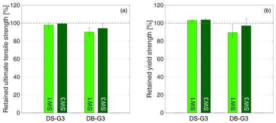
Figure 9.
Direct tensile tests on aged bare textiles—retained; (a) ultimate tensile strength and (b) yield strength for G3 textile in straight (DS) and bent (DB) configurations.
The tensile performance of the textile in straight configuration proved to be basically unaffected by aging in saltwater (Δσf = −2.1% and −0.6%, Δσy = +3.1% and +3.6%, ΔEf = −2.1% and −1.2% after 1000 and 3000 h, respectively). On the other hand, bending the cords affected their durability, due to the damage to the zinc coating and the subsequent penetration of salts and corrosion of cords, as demonstrated by the decrease in ultimate and yield strengths and tensile modulus of elasticity (Δσf = −9.9% and −5.8%, Δσy = −10.4% and −3.0%, ΔEf = −10.1% and −8.2%, after 1000 and 3000 h, respectively).
3.3.2. SRG Composite Specimens
N = 5 tensile tests (kn = 2.33) were carried out for each of the SRG systems listed in Table 4, which collects the difference in ultimate tensile strength compared to the unaged system (Δσu). In Figure 10, specimens aged in dry heat for 1000 and 3000 h (DH1 and DH3) are in grey, those exposed to 20 freeze–thaw cycles (FT20) are in pink, those aged in water for 1000 and 3000 h (WT1 and WT3) are in blue, those aged in saltwater for 1000 and 3000 h (SW1 and SW3) are in green, those aged in alkali soil (AKS) are in brown and, finally, those aged in alkaline solution for 1000 and 3000 h (AK1 and AK3) are in orange/red.
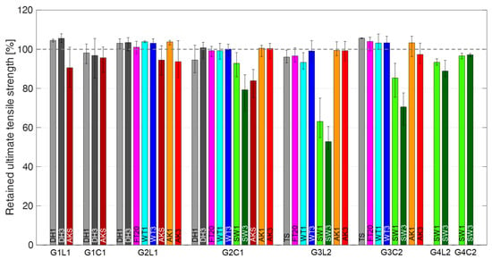
Figure 10.
Direct tensile tests on aged SRG composites—Retained ultimate tensile strength vs. SRG composite type and aging process. Systems: G1L1—steel textile G1 and lime mortar, G1C1—steel textile G1 and thixotropic cement-like mortar, G2L1—steel textile G1 and lime mortar, G2C1—steel textile G2 and thixotropic cement-like mortar, G3L2—steel textile G3 and fibre-reinforced lime mortar, G3C2—steel textile G3 and fibre-reinforced thixotropic cement-like mortar, G4L2—steel textile G3 and fibre-reinforced lime mortar, G4C2—steel textile G3 and fibre-reinforced thixotropic cement-like mortar. Conditioning processes: dry heat—1000 and 3000 h (DH1, DH3), 20 freeze–thaw cycles (FT20), water immersion—1000 and 3000 h (WT1, WT3), saltwater immersion—1000 and 3000 h (SW1, SW3), alkali soil (AKS), finally, alkaline solution immersion—1000 and 3000 h (AK1, AK3).
Regardless of the conditioning process, the aged specimens showed the same stress–strain curves and failure modes of the unaged ones. The steel cords broke almost simultaneously at a crack, unlike the G2 fabric, whose failure after the peak was characterised by staircase behaviour, with time-delayed failure of the cords and the total ejection of the matrix.
SRG composite specimens aged through freeze–thaw cycles showed a negligible decrease in strength (Δσu = −0.7% for G2C1 and −3.5% for G3L2). In some cases, an increase in strength was observed (Δσu = 1.0% for G2L1 and 4.0% for G3C2), due to the additional curing of the mortar promoted by the water supplied during aging [25,26]. Indeed, the prolonged availability of water likely promoted the continuation of hydration in cement-based systems and carbonation or hydraulic reactions in lime mortars, improving the cohesion and reducing early-age microcracking of the matrix, thus enhancing the adhesion with the steel cords [46,47,48].
An almost negligible decrease in strength was noted after aging in water (Δσu = −0.8% for G2C1-WT1, −6.7% for G3L2-WT1 and −0.9% for G3L2-WT3), the variations being within the usual scatter of tests results. Also, in this case, an increase in strength was observed for some systems (Δσu = 3.8% for G2L1-WT1, 3.0% for G2L1-WT3, 0.1% for G2C1-WT3, 3.2% for G3C2-WT1 and 3.3% for G3C2-WT3), due to the additional curing.
Different tensile behaviour was exhibited by aged SRG composite specimens after conditioning in saline environment, depending on the mortar used and the type of coating. The saline solution caused serious corrosion of steel wires for G3 textile-based systems, which resulted in a decrease of strength (Δσu = −3 ÷ −48%) and stiffness (ΔEIII = −7 ÷ −20%) of the tested SRG composites, and in a change of their tensile behaviour, from quasi-ductile to brittle, in particular for the G2 textile-based systems. SRG systems with lime-based mortars exhibited larger strength reductions than the ones with cement-like mortars (Δσu = −36.9% for G3L2-SW1, −47.2% for G3L2-SW3, −6.7% for G4L2-SW1 and −11.1% for G4L2-SW3), due to the higher vapour permeability of the matrices (Δσu = −7.2% for G2C1-SW1, −20.7% for G2C1-SW3, −14.7% for G3C2-SW1, −29.4% for G3C2-SW3, −3.4% for G4C2-SW1 and −2.8% for G4C2-SW3), facilitating the solution reaching the textile and promoting corrosion (Figure 11a–d). Additionally, a higher strength loss was observed for the composites with G2 and G3 textiles (mass of the zinc coating equal to 32 g/kg and 23 g/kg, respectively) than for those with G4 (zinc mass 38 g/kg). These results highlighted the crucial role of the zinc coating in ensuring the durability of galvanized SRG composites. In particular, the thickness of the protective zinc layer proved to be a key factor in preventing corrosion of the steel cords, with thinner coatings leading to significantly higher strength degradation. These findings suggest that minimum requirements for zinc coating thickness should be established and strictly enforced in the development, certification, and use of SRG systems to ensure long-term performance and reliability.
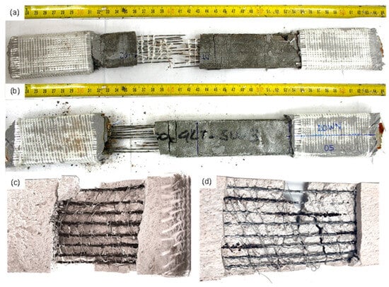
Figure 11.
Direct tensile tests on aged SRG composites—failure modes and cord damage: (a) cement-based composite specimen after 1000 h of saltwater aging; (b) same type of specimen after 3000 h; (c) corrosion on cords after 1000 h for fibre-reinforced lime mortar-based systems; (d) corrosion on cords after 3000 h for fibre-reinforced cement-based composites.
Figure 12a,b shows the state of steel cords before (UN) and after aging in saltwater (SW1, SW3) for both cement-like (Figure 12a) and lime-based (Figure 12b) systems. The comparison between UN and SW1/SW3 cords highlights that, in addition to damage to the zinc coating, corrosion of the steel affected the cord-to-matrix adhesion, and increased with increasing aging duration, and was more severe for lime-based systems. Indeed, in UN specimens, traces of mortar are still present on the external surface of cords after testing, which were not found in the aged systems.
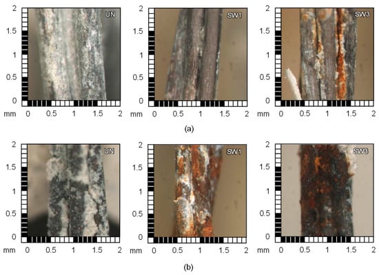
Figure 12.
Direct tensile tests on aged SRG composites—failure modes and cord damage: microscopic images of steel cords—(a) cement-like mortar-based composites and (b) lime mortar-based ones.
Aging in alkali soil produced a remarkable decrease in tensile strength, due to the acidity of the aging environment and the presence of cellulose-destroying microorganisms. In the case of the systems comprising G1, the strength decrease was higher for lime-based SRGs (Δσu = −9.5% for G1L1) than for cement-based ones (Δσu = −4.4% for G1L1), due to the higher permeability of the mortar. In contrast, the trend was reversed for systems with G2, and the higher strength decrease was observed for cement mortar (Δσu = −16.1% for G2C1) than for lime ones (Δσu = −5.6% for G2L1).
Overall, the composites showed great resistance to alkaline attack, regardless of the system evaluated. In some cases, there was even a positive difference (Δσu = 3.7% for G2L1-AK1, 0.5% for G2C1-AK1, 0.3% for G2C1-AK3 and 3.2% for G3C2-AK1), reflecting an increase in peak stress, attributable to the additional curing favoured by water during aging. Consistently, G2-C1 composites showed higher stress at the first crack and a more uniform distribution of cracks than the non-aged specimens. On the other hand, some systems showed a slight reduction in strength (Δσu = −6.4% for G2L1-AK3, −0.6% for G3L2-AK1, −0.8% for G3L2-AK3 and −2.7% for G3C2-AK3), although these decreases were probably due to the variability of the test results rather than alkali induced degradation. Stiffness remained unchanged for all mortar types and visually the samples showed a residual chalky white surface due to solution deposits.
4. Bond Tests
4.1. Experimental Setup
To investigate the SRG-to-substrate bond, single-lap shear bond tests were performed, in accordance with existing recommendations [10,12], using an MTS machine with 500 kN capacity. Prismatic substrates (concrete or brick masonry) were used, measuring 120 mm (width) × 120 mm (thickness) × 320 mm (height). A G1 textile strip 50 mm wide (8 cords, 4.2 mm2 total cross-sectional area) and 600 mm long was bonded to the substrate. The bonded area was 50 mm wide, 260 mm long and 10 mm thick [49]. To minimize edge effects, an unbonded length of 30 mm was left from the loaded end of the substrate [49]. Specimens were cured for 28 days at 20–25 °C temperature and >90% relative humidity (R.H.).
The experimental setup is shown in Figure 13. The substrate prism was blocked in a steel frame made of two 20 mm thick plates connected by four threaded rods. The wedges of the machine gripped the lower plate and the unbonded textile, which was pulled upwards under displacement control at a 0.2 mm/min stroke rate. As in tensile tests on textiles (§3.1), aluminium tabs were glued with epoxy resin at the end of the unbonded textile. The upper plate was shaped to allow, by correct positioning of the specimen in the frame, the alignment of the textile with the load axis, to avoid eccentricity. The compression exerted by tightening the bolts of the rods, together with an additional system of counter-bolts, precluded any rotations of the substrate. Neoprene sheets were interposed between the substrate and the steel plates to provide a uniform distribution of the compressive stresses.
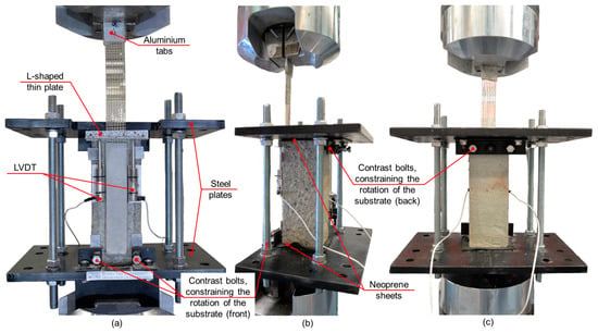
Figure 13.
Single-lap shear bond test setup: (a) front, (b) side and (c) back view.
During tests, both the axial tensile stress in the textile (σ) and the textile-to-substrate relative displacement (slip, sb) were recorded. The former, assumed to be uniformly distributed in the steel cords [49], was evaluated as the ratio between the load measured at 10 Hz by the integrated load cell and the cross-sectional area of the textile (4.2 mm2). The latter was derived from the displacement measured by two LVDTs fixed to the substrate, at the two side of the bonded area, and put in contrast with an L-shaped aluminium plate glued to the textile at a distance dL = 3–5 mm from the loaded end of the bonded area (Figure 13). The slip (sb) was calculated as the difference between the average displacement recorded by the LVDTs and the elastic elongation ΔL = σ⋅dL/Ef of the unbonded textile over dL. A pre-load of 3–5% of the expected failure load was applied prior to testing.
4.2. Tests on Unaged Specimens
Shear bond tests were conducted on SRG composites made of G1 textile applied with lime mortar to masonry substrates and with cement mortar to concrete substrates. Table 5 collects the number of specimens (N), the average ultimate axial stress (σb), also referred to as bond strength, the corresponding coefficient of variation (CV_σb), the differences with respect to unaged specimens (Δσb), the slip corresponding to σb (sb), and the prevalent failure mode (FM) classified according to [12].

Table 5.
Results of shear bond tests.
The main failure mode, regardless of the system and substrate used, consisted of detachment at the textile-to-matrix interface (mode C, in Table 5). Accordingly, the bond strength was lower than the ultimate tensile strength of the bare textile, i.e., −37.4% for specimens with lime mortar (DS-G1-UN vs. SB-M-G1L-UN) and −19.4% for the ones with cement-like mortar (DS-G1-UN vs. SB-K-G1C1-UN).
4.3. Tests on Aged Specimens
The results of the shear bond tests on aged specimens are collected in Table 5 and shown in Figure 14. The retained bond strength (ratio between the bond strength of the aged specimen and that of the corresponding unaged specimen) is illustrated in Figure 14. Specimens aged with 20 and 40 freeze–thaw cycles (FT20 and FT40) are in pink and purple, respectively; those aged with wetting–drying cycles in water (WTC) are in blue; and those aged with wetting–drying cycles in saltwater (salt crystallisation cycles, SWC) are in green.
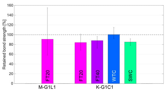
Figure 14.
Shear bond tests on aged specimens—retained bond strength vs. system type and aging process.
In specimens aged with freeze–thaw cycles, regardless of the system and substrate used, the textile showed the presence of oxide on the cords along the unbonded zone (Figure 15a), which was more pronounced for specimens subjected to 40 freeze–thaw cycles. With regard to the bonded area, rust was distributed over all the cords, more concentrated at the loaded (first unbonded section) end for FT20 (Figure 15b), whilst for FT40 rust was detected mainly on the external cords (the first and eighth ones) (Figure 15c). Like unaged specimens, failure occurred at the textile-to-matrix interface (failure mode C). A decrease in bond strength was obtained, which was lower for lime-based SRGs bonded to masonry substrate (Δσb = −9.3% for SB-M-G1L1-FT20) and slightly higher for cement-based SRGs bonded to concrete (Δσb = −15.9% for SB-K-G1C1-FT20 and −12.0% for SB-K-G1C1-FT40). This reduction in strength is due to the formation of micro-cracks in the mortar caused by the volumetric expansion of water in the micropores during the freezing phase, a phenomenon that was more pronounced for cement-based SRGs due to the lower porosity of the cement matrix compared to the lime one.
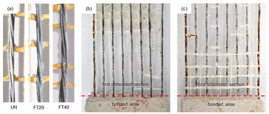
Figure 15.
Shear bond tests—(a) comparison of unaged (UN) and aged after 20 (FT20) and 40 (FT40) freeze–thaw cycles, (b) presence of sparse rust on all cords after FT20 aging, and (c) on edge cords after FT40 aging.
In the specimens aged with wetting–drying cycles in water (WTC), rust only formed near and within the loaded end of the bonded area. This did not entail a bond strength decrease (Δσb = +0.4% for SB-K-G1C1-WTC). The failure mode was similar to unaged specimens (C), as detachment occurred at the textile-to-matrix interface.
All specimens aged by wetting–drying cycles in saltwater (SWC) exhibited similar damage state of the cords, with rust formation mainly at the first unbonded section and within the matrix near the unbonded section (Figure 16). Also, in this case, failure occurred by textile detachment at the interface with mortar (mode C), with a decrease in strength with respect to the unaged system Δσb = −14.9%, due to micro-cracking induced by salt crystallisation in the mortar. This strength decrease was similar to that caused by freeze–thaw cycles, implying that both water volume expansion and salt crystallization caused comparable micro-cracking in the mortar, likely due to its low porosity.
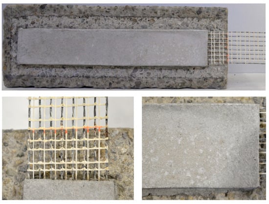
Figure 16.
Shear bond tests—SRG composite composed of G1 steel textile and C1 mortar bonded to concrete substrate after aging through salt crystallization cycles (SB-G1C1-K-SWC).
In summary, the shear bond tests showed that the localized corrosion in the initial unbonded section of the textile caused by freeze–thaw cycles led to an early detachment at the textile-to-matrix interface and a reduction in bond strength. This was associated with the micro-cracking in the mortar caused by the expansion of water within its micropores during freezing. In SRGs incorporating cement-based mortars on concrete substrates both freeze–thaw and salt crystallization cycles led to the formation of rust on the steel cords embedded in the matrix close to the unbonded section, and by an interfacial debonding governed failure. Due to the low porosity of the cementitious mortar, the micro-damaging effects of the cycles were comparable and led to a bond strength decrease of 14% on average, which was higher than that of the lime-based SRGs (9%).
Given the crucial importance of the composite-to-substrate load transfer mechanism for the effectiveness of the externally bonded SRG reinforcement and, therefore, for the safety of the retrofitted structural member along its expected service life, this degradation of bond strength should be considered in the strengthening design.
5. Lap-Tensile Tests
5.1. Experimental Setup
Lap-tensile tests were performed to determine the relative tensile strength at the textile overlap area [10]. Specimens comprised two 450 mm long strips of G1 textile with five cords (2.69 mm2 cross-sectional area), overlapped for a length of 300 mm, and embedded in either lime or cement mortars. The overlap length of 300 mm was selected in accordance with existing design guidelines [7,50], as the minimum one providing effective stress transfer between textile layers at overlaps. The composite specimen had a total length of 600 mm, a width of 40 mm and a thickness of 10 mm. Composites were manufactured with G1 and G2 textiles combined with either cement-like (LT-G1C1, LT-G2C1) or lime (LT-G1L1, LT-G2L1) mortars. The same experimental setup of tensile tests on SRG composites was used (§3.1). The stress was calculated as the load recorded by the integrated load cell divided by the cross-sectional area of one layer of textile.
5.2. Tests on Unaged Specimens
Table 6 collects textile type, test code and number of specimens (N), the average ultimate tensile stress (σlap), the corresponding coefficient of variation (CV_σlap), and the characteristic (0.05-fractile) ultimate stress (σlap,k). The prevalent failure mode (FM), labelled as R for cords rupture outside the overlap area and D for detachment at the textile-to-matrix interface along the overlap length, is also indicated.

Table 6.
Results of lap-tensile tests.
The stress–strain curves are shown in Figure 17. As with SRG composites, a three-stage behaviour was exhibited.
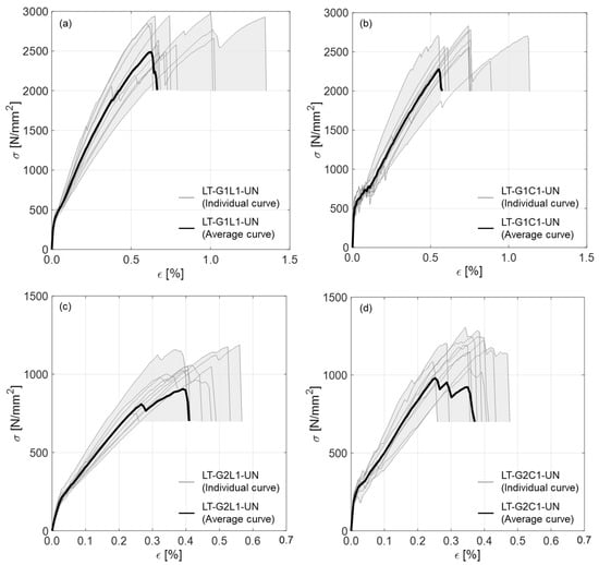
Figure 17.
Lap-tensile (LT) stress (σ) vs. strain (ε) response curves of unaged (UN) SRG composite specimens: (a) G1L1—steel textile G1 and lime mortar, (b) G1C1—steel textile G1 and thixotropic cement-like mortar, (c) G2L1—steel textile G1 and lime mortar, (d) G2C1—steel textile G2 and thixotropic cement-like mortar.
In lap-tensile tests, the size of the spacing between cords resulted as crucial for the textile-matrix-textile stress transfer. Specimens with G1 (6.35 mm cords spacing) failed by the tensile rupture of steel cords outside the overlap length (Figure 18a), indicating an adequate stress transfer, the average value of the ultimate stress (σlap) being slightly lower than that obtained in the direct tensile tests (σlap = 2783.2 MPa vs. σu = 2969.1 MPa for G1L1 and σlap = 2675.4 MPa vs. σu = 2871.5 MPa for G1C1). On the other hand, SRGs with G2, in which the spacing between cords was smaller (3.18 mm), failed by detachment at the matrix–textile interface along the overlap length (Figure 18b), and the ultimate lap-tensile stress was about 60% lower than that of the corresponding SRG composites under tensile tests (σlap = 1140.8 MPa vs. σu = 2918.3 MPa for G2L1 and σlap = 1227.4 MPa vs. σu = 2964.0 MPa for G2C1).
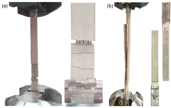
Figure 18.
Lap-tensile tests—failure mode of specimens with (a) G1 and (b) G2 textiles.
5.3. Tests on Aged Specimens
As anticipated in §2.1, only systems made of G2 textile, embedded in both lime and cement mortar, were tested after artificial aging. Table 6 collects test results, including the differences with respect to unaged specimens (Δσlap), which are also shown in Figure 19 in terms of retained strength. In the figure, specimens aged in water for 1000 and 3000 h (WT1 and WT3) are in blue, those aged in saltwater for 1000 and 3000 h (SW1 and SW3) are in green, and specimens aged in alkali solution (AK1 and AK3) are in orange/red.
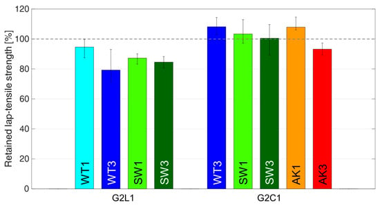
Figure 19.
Lap-tensile tests—retained lap-tensile strength vs. system type and aging process.
The failure mode of the specimens aged in water was similar to that of the unaged ones (mode D), but different ultimate strengths were obtained depending on the mortar used. Specimens comprising the lime mortar exhibited a strength decrease (Δσlap = −5.4% for G2L1-WT1 and −20.7% for G2L1-WT3) due to lime leaching occurring during aging, which caused a reduction of the strength of the matrix, thus affecting the stress transfer [51]. Conversely, a strength increase was attained by cement-based systems (Δσlap = +8.1% for G2C1-WT3), following further curing of the mortar during aging.
Different behaviour was also noted for the salt-aged specimens, depending on whether the mortar was lime-based or cement-based. Specimens with the lime mortar showed a strength decrease (Δσlap = −12.8% for G2L1-SW1 and −15.5% for G2L1-SW3), due to the micro-damaging caused by salt crystallization and the formation of rust on steel cords (Figure 20a). On the other hand, a strength increase was observed in specimens with cement mortar (Δσlap = +3.3% for G2C1-SW1 and +0.5% for G2C1-SW3) due to the further curing under water and the smaller size of micro-pores (with respect to those in lime mortar) reducing the permeability (Figure 20b).

Figure 20.
Condition of the steel cords after 3000 h aging in substitute ocean water of the specimens with (a) lime mortar and with (b) cement mortar.
Finally, as regards aging in alkaline solution, in cement-based SRGs an increase of the ultimate strength was observed after 1000 h (Δσlap = +7.9% for G2C1-AK1), whereas the aggressive environment led to the deterioration of the matrix after 3000 h (Δσlap = −6.8% for G2C1-AK3). Initial curing and hardening of the cement mortar were followed by deterioration due to prolonged exposure to the aggressive alkaline environment.
6. Conclusions
The durability of eight SRG systems, made of four galvanized steel textiles embedded in two lime mortars and two cement mortars, was assessed through direct tensile, shear bond, and lap-tensile tests. Aging processes included immersion in water, saltwater, alkaline solutions, wet–dry cycles, freeze–thaw cycles, high temperatures, and exposure to alkali soil. The following conclusions can be drawn:
- Tensile behaviour
- For bare steel textile, aging in substitute ocean water did not affect the mechanical performance, but when combined with bending a weak point develops in the zinc coating, allowing salt to penetrate and cause localized corrosion.
- Conversely, for SRG composites, aging in substitute ocean water was the most aggressive condition, with a greater strength decay in SRGs with lime mortars (up to 50%) compared to those with cement mortars (20%).
- SRG composites exhibited different failure modes depending on cord spacing and matrix type. Large cord spacing caused simultaneous rupture of cords, while denser textiles failed progressively.
- Textiles with thin zinc coatings (i.e., lower than 30 g/kg) may not be suitable for application with lime-based mortar as they exhibit significant strength decay (up to 50%) under saltwater aging conditions.
- Immersion in alkaline solutions caused no deterioration, while aging in alkali soil led to a significant decrease in strength.
- Freeze–thaw cycles and exposure to high temperatures had no significant impact on mechanical performance.
- Bond behaviour
- Freeze–thaw cycles led to corrosion near the textile-to-matrix interface, promoting detachment and decrease in bond capacity due to micro-cracking.
- SRGs with cement-like matrices on concrete substrates showed stable behaviour after freeze–thaw aging and salt crystallization, with bond strength decreasing by around 14%.
- Freeze–thaw aging resulted in a greater strength reduction in cement-based specimens (−12% to −16%) than in lime-based ones (−9%), likely due to the lower porosity of cement mortars.
- Lap-Tensile behaviour
- The load transfer capacity at textile overlaps was influenced by cord spacing and textile-to-matrix interlocking. Larger spacing (6.35 mm) resulted in tensile rupture outside the overlap length, while smaller spacing (3.18 mm) led to failure by debonding along the overlap.
- Specimens with lime mortar showed a 5–20% decrease in mechanical performance after aging. In contrast, those with cement mortar exhibited higher strength due to continuous curing during immersion and better protection from permeated salts. However, prolonged exposure to alkaline solutions caused a 7% deterioration in cement matrices.
The outcomes of this experimental investigation highlighted the important role played by cord spacing and mortar properties in the mechanical behaviour of SRG composites, as well as the influence of the zinc coating and matrix permeability on their durability. The thickness of the protective zinc layer emerged as a crucial factor, suggesting that it should be considered a main requirement for the certification and use of SRG systems with galvanized cords.
Although a micro-scale investigation (e.g., scanning electron microscopy—SEM, energy-dispersive X-ray spectroscopy—EDS, porosity measurements) could yield a more comprehensive characterisation of morphology and extent of corrosion, and of the influence of mortar type on vapor permeability, this study provided significant insights into the degradation of the mechanical properties of SRG composites after multiple aging conditions, with direct relevance for structural engineering applications.
Overall, the attack of salts on the corrosion of steel cords is more deteriorating in the presence of insufficient zinc coating thickness (i.e., lower than 30 g/kg) and with lime mortar matrices. This negatively affects tensile strength and cord–matrix adhesion. Moreover, freeze–thaw and salt crystallisation cycles influence the mechanical properties of the mortar, impacting both cord–matrix and matrix–substrate adhesion.
Clearly, given the broad variability of composites, substrates, and exposure conditions found in structural applications, the results obtained under laboratory conditions cannot be directly extended to all scenarios that may arise in rehabilitation practice. That said, it should be emphasized that the significant strength decay observed in some samples after artificial aging raise concerns about the indiscriminate use of galvanized SRG composites for structural reinforcement. Therefore, appropriate protective measures and/or design safety factors must be carefully evaluated to ensure their long-lasting durability. Current building codes [7,8,50] do not provide environmental reduction coefficients specifically calibrated for SRGs, nor differentiated for particular exposure conditions, and further experimental research is needed to fill this gap.
As regards methodology, this investigation showed that direct tensile tests on SRG composites after standard aging processes (full immersion) provide important but not sufficient information to fully characterize the long-term behaviour of externally bonded SRG reinforcements. First, tensile test results may not directly translate to textile-to-substrate or textile-to-textile load transfer behaviour, key mechanisms for structural effectiveness. Second, wet–dry cycles promote salt crystallization, even without high salt concentrations. Finally, exposure to alkali soil is more aggressive than immersion in calcium hydroxide solution, highlighting the aggressive environment caused by rising damp and/or variable conditions where water, salts, and oxygen cyclically affect the composite. Difficulties remain in correlating accelerated artificial aging performed in the laboratory with real exposure conditions in structures, suggesting the adoption of more severe and comprehensive laboratory test protocols as a precautionary measure to ensure the effectiveness and durability of SRG systems.
Author Contributions
Conceptualization, S.F., P.M., S.D.S. and G.d.F.; methodology, S.F., P.M., S.D.S. and G.d.F.; validation, S.F. and P.M.; formal analysis, S.F. and P.M.; investigation, S.F. and P.M.; data curation, S.F. and P.M.; writing—original draft preparation, S.F. and P.M.; writing—review and editing, S.D.S. and G.d.F.; visualization, S.F. and P.M.; supervision, S.D.S. and G.d.F.; project administration, S.D.S. and G.d.F. All authors have read and agreed to the published version of the manuscript.
Funding
The authors would like to thank the Italian Civil Protection Department for the funding granted through the “DPC-ReLUIS” agreement (2024–2026) and the National Recovery and Resilience Plan (PNRR), Mission 4, Component 2, Investment 1.3 supported by the “Next Generation EU” Programme of the European Union within the Research Project “CHANGES Cultural heritage Active innovation for a sustainable society of the next generation”.
Institutional Review Board Statement
Not applicable.
Informed Consent Statement
Not applicable.
Data Availability Statement
The original contributions presented in this study are included in the article. Further inquiries can be directed to the corresponding author.
Conflicts of Interest
The authors declare no conflicts of interest.
References
- Hafner, I.; Kišiček, T.; Gams, M. Review of Methods for Seismic Strengthening of Masonry Piers and Walls. Buildings 2023, 13, 1524. [Google Scholar] [CrossRef]
- Barton, B.; Wobbe, E.; Dharani, L.R.; Silva, P.; Birman, V.; Nanni, A.; Alkhrdaji, T.; Thomas, J.; Tunis, G. Characterization of reinforced concrete beams strengthened by steel reinforced polymer and grout (SRP and SRG) composites. Mater. Sci. Eng. A 2005, 412, 129–136. [Google Scholar] [CrossRef]
- Huang, X.; Birman, V.; Nanni, A.; Tunis, G. Properties and potential for application of steel reinforced polymer and steel reinforced grout composites. Compos. Part B Eng. 2005, 36, 73–82. [Google Scholar] [CrossRef]
- Irandegani, M.A.; Zhang, D.; Shadabfar, M.; Kontoni, D.P.N.; Iqbal, M. Failure Modes of RC Structural Elements and Masonry Members Retrofitted with Fabric-Reinforced Cementitious Matrix (FRCM) System: A Review. Buildings 2022, 12, 653. [Google Scholar] [CrossRef]
- ACI 549R-97; Report on Ferrocement. American Concrete Institute: Farmington Hills, MI, USA, 1997.
- Asghari, H.; Omeman, Z.; Noel, M.; Hajiloo, H. Tensile properties of carbon fabric-reinforced cementitious matrix (FRCM) at high temperatures. Structures 2023, 55, 85–96. [Google Scholar] [CrossRef]
- ACI 549.6R-20; Guide to Design and Construction of Externally Bonded Fabric-Reinforced Cementitious Matrix (FRCM) and Steel-Reinforced Grout (SRG) Systems for Repair and Strengthening Masonry Structures. American Concrete Institute: Farmington Hills, MI, USA, 2020.
- Italian High Council of Public Works (CSLLPP). Linea Guida per la Progettazione, L’esecuzione e la Manutenzione di Interventi di Consolidamento Strutturale Mediante L’utilizzo di Sistemi di Rinforzo FRCM; CSLLPP: Rome, Italy, 2019. [Google Scholar]
- AC434; Acceptance Criteria for Masonry and Concrete Strengthening Using Fabric-Reinforced Cementitious Matrix (FRCM) and Steel Reinforced Grout (SRG) Composite Systems. ICC-ES: Whittier, CA, USA, 2016.
- EAD 340275-00-0104; Externally-Bonded Composite Systems with Inorganic Matrix for Strengthening of Concrete and Masonry Structures. EOTA: Brussels, Belgium, 2018.
- Italian High Council of Public Works (CSLLPP). Linee Guida per L’identificazione, La Qualificazione ed il Controllo di Accettazione di Compositi Fibrorinforzati a Matrice Polimerica (FRP); CSLLPP: Rome, Italy, 2019. [Google Scholar]
- Italian High Council of Public Works (CSLLPP). Linee Guida per L’identificazione, la Qualificazione ed il Controllo di Accettazione di Compositi Fibrorinforzati a Matrice Inorganica (FRCM); CSLLPP: Rome, Italy, 2018. [Google Scholar]
- Canestri, M.; Ferretti, F.; Sassoni, E.; Mazzotti, C. On the behaviour of FRCM fibres in saturated alkaline solution. In Life-Cycle of Structures and Infrastructure Systems, 1st ed.; CRC Press: Boca Raton, FL, USA, 2023; pp. 2812–2819. [Google Scholar] [CrossRef]
- Razavizadeh, A.; Ghiassi, B.; Oliveira, D.V. Bond behavior of SRG-strengthened masonry units: Testing and numerical modeling. Constr. Build. Mater. 2014, 64, 387–397. [Google Scholar] [CrossRef]
- De Santis, S.; Ceroni, F.; de Felice, G.; Fagone, M.; Ghiassi, B.; Kwiecień, A.; Lignola, G.P.; Morganti, M.; Santandrea, M.; Valluzzi, M.R.; et al. Round Robin Test on tensile and bond behavior of Steel Reinforced Grout systems. Compos. Part B Eng. 2017, 127, 100–120. [Google Scholar] [CrossRef]
- De Santis, S. Bond behavior of Steel Reinforced Grout for the extrados strengthening of masonry vaults. Constr. Build. Mater. 2017, 150, 367–382. [Google Scholar] [CrossRef]
- Ascione, F.; Lamberti, M.; Napoli, A.; Realfonzo, R. Experimental bond behavior of Steel Reinforced Grout systems for strengthening concrete elements. Constr. Build. Mater. 2020, 232, 117105. [Google Scholar] [CrossRef]
- Thermou, G.E.; De Santis, S.; de Felice, G.; Alotaibi, S.; Roscini, F.; Hajirasouliha, I.; Guadagnini, M. Bond behaviour of Multi-Ply Steel Reinforced Grout Composites. Constr. Build. Mater. 2021, 305, 124750. [Google Scholar] [CrossRef]
- Katsamakas, A.A.; Papanikolaou, V.K.; Thermou, G.E.; Katakalos, K. Experimental and numerical investigation of the uniaxial compression behavior of SRG-jacketed R/C columns. Structures 2022, 44, 603–617. [Google Scholar] [CrossRef]
- Borri, A.; Castori, G. Indagini sperimentali sulla durabilità di materiali compositi in fibra d’acciaio. In Proceedings of the XIV Convegno ANIDIS, Bari, Italy, 18–22 September 2011. [Google Scholar]
- ASTM B117; Standard Practice for Operating Salt Spray (Fog) Apparatus. ASTM International: West Conshohocken, PA, USA, 2009; (current version 2019).
- ASTM D1141; Standard Practice for Preparation of Substitute Ocean Water. ASTM International: West Conshohocken, PA, USA, 2013.
- De Santis, S.; de Felice, G. Steel reinforced grout systems for the strengthening of masonry structures. Compos. Struct. 2015, 134, 533–548. [Google Scholar] [CrossRef]
- Signorini, C.; Nobili, A. Comparing durability of steel reinforced grout (SRG) and textile reinforced mortar (TRM) for structural retrofitting. Mater. Struct. 2021, 54, 131. [Google Scholar] [CrossRef]
- Franzoni, E.; Gentilini, C.; Santandrea, M.; Carloni, C. Durability of steel FRCM-masonry joints: Effect of water and salt crystallization. Mater. Struct. 2017, 50, 201. [Google Scholar] [CrossRef]
- Franzoni, E.; Gentilini, C.; Santandrea, M.; Carloni, C. Effects of rising damp and salt crystallization cycles in FRCM-masonry interfacial debonding: Towards an accelerated laboratory test method. Constr. Build. Mater. 2018, 175, 225–238. [Google Scholar] [CrossRef]
- Bencardino, F.; Nisticò, M.; Verre, S. Experimental investigation and numerical analysis of bond behavior in SRG-strengthened masonry prisms using UHTSS and stainless-steel fibers. Fibers 2020, 8, 8. [Google Scholar] [CrossRef]
- Fares, S.; Fugger, R.; De Santis, S.; de Felice, G. Strength, bond and durability of stainless Steel Reinforced Grout. Constr. Build. Mater. 2022, 322, 126465. [Google Scholar] [CrossRef]
- Liberotti, R.; Cluni, F.; Gusella, V. Unreinforced masonry structures’ seismic improvement with FRCM: The experience of the Vanvitellian Palazzo Murena of Perugia. In Proceedings of the 12th International Conference on Structural Analysis of Historical Constructions SAHC, Barcelona, Spain, 29 September–1 October 2021; pp. 1651–1662. [Google Scholar] [CrossRef]
- Shi, J.; Ming, J. Influence of defects at the steel–mortar interface on the corrosion behavior of steel. Constr. Build. Mater. 2017, 136, 118–125. [Google Scholar] [CrossRef]
- Wong, H.S.; Angst, U.M.; Geiker, M.R.; Isgor, O.B.; Elsener, B.; Michel, A.; Alonso, M.C.; Correia, M.J.; Pacheco, J.; Gulikers, J.; et al. Methods for characterising the steel–concrete interface to enhance understanding of reinforcement corrosion: A critical review by RILEM TC 262-SCI. Mater. Struct. 2022, 55, 124. [Google Scholar] [CrossRef]
- Incerti, A.; Rinaldini, V.; Santandrea, M.; Carloni, C.; Mazzotti, C. Effect of Density and Number of Layers of Fiber Sheets and End Anchors on the Flexural Capacity of SRG-Strengthened RC Beams. Buildings 2025, 15, 1005. [Google Scholar] [CrossRef]
- Lee, H.S.; Singh, J.K.; Ismail, M.A.; Bhattacharya, C.; Seikh, A.H.; Alharthi, N.; Hussain, R.R. Corrosion mechanism and kinetics of Al–Zn coating deposited by arc thermal spraying process in saline solution at prolonged exposure periods. Sci. Rep. 2019, 9, 3399. [Google Scholar] [CrossRef]
- Singh, J.K.; Mandal, S.; Adnin, R.J.; Lee, H.-S.; Yang, H.-M. Role of coating processes on the corrosion kinetics and mechanism of zinc in artificial seawater. Materials 2021, 14, 7464. [Google Scholar] [CrossRef]
- De Santis, S.; Meriggi, P.; De Felice, G. Durability of steel reinforced grout composites. In Brick and Block Masonry—From Historical to Sustainable Masonry, 1st ed.; CRC Press: Boca Raton, FL, USA, 2020; pp. 357–363. [Google Scholar] [CrossRef]
- Fares, S.; Meriggi, P.; De Santis, S.; de Felice, G. Insight on the Durability of Steel Reinforced Grout (SRG) Systems for the Strengthening of Historical Constructions. In Proceedings of the 5th International Conference on Protection of Historical Constructions PROHITECH, Naples, Italy, 18–20 June 2025; Lecture Notes in Civil Engineering. Springer: Cham, Switzerland, 2025; Volume 595, pp. 431–439. [Google Scholar] [CrossRef]
- EN 998-2; Specification for Mortar for Masonry—Part 2: Masonry Mortar. CEN: Brussels, Belgium, 2016.
- EN 1015-11; Methods of Test for Mortar for Masonry—Part 11: Determination of Flexural and Compressive Strength of Hardened Mortar. CEN: Brussels, Belgium, 2019.
- ASTM D3045; Standard Practice for Heat Aging of Plastics Without Load. ASTM International: West Conshohocken, PA, USA, 2018.
- ASTM E104; Standard Practice for Maintaining Constant Relative Humidity by Means of Aqueous Solutions. ASTM International: West Conshohocken, PA, USA, 2002.
- ASTM D2247; Standard Practice for Testing Water Resistance of Coatings in 100% Relative Humidity. ASTM International: West Conshohocken, PA, USA, 2011.
- ASTM D7705/D7705M; Standard Test Method for Alkali Resistance of Fiber Reinforced Polymer (FRP) Matrix Composite Bars Used in Concrete Construction. ASTM International: West Conshohocken, PA, USA, 2019.
- De Santis, S.; Carozzi, F.G.; de Felice, G.; Poggi, C. Test methods for textile reinforced mortar systems. Compos. Part B Eng. 2017, 127, 121–132. [Google Scholar] [CrossRef]
- EN 1990; Eurocode 0: Basis of Structural Design. CEN: Brussels, Belgium, 2002.
- de Felice, G.; D’Antino, T.; De Santis, S.; Meriggi, P.; Roscini, F. Lessons learned on the tensile and bond behavior of Fabric Reinforced Cementitious Matrix (FRCM). Front. Built Environ. 2020, 6, 5. [Google Scholar] [CrossRef]
- Lanas, J.; Álvarez-Galindo, J.I. Masonry repair lime-based mortars: Factors affecting the mechanical behavior. Cem. Concr. Res. 2003, 33, 1867–1876. [Google Scholar] [CrossRef]
- Elert, K.; Rodríguez-Navarro, C.; Pardo, E.S.; Hansen, E.; Cazalla, O. Lime mortars for the conservation of historic buildings. Stud. Conserv. 2002, 47, 62–75. [Google Scholar] [CrossRef]
- Mehta, P.K.; Monteiro, P.J.M. Concrete: Microstructure, Properties, and Materials, 4th ed.; McGraw-Hill Education: New York, NY, USA, 2014; ISBN 9780071797870. [Google Scholar]
- de Felice, G.; Aiello, M.A.; Caggegi, C.; Ceroni, F.; De Santis, S.; Garbin, E.; Gattesco, N.; Hojdys, Ł.; Krajewski, P.; Kwiecień, A.; et al. Recommendation of RILEM Technical Committee 250-CSM: Test method for Textile Reinforced Mortar to substrate bond characterization. Mater. Struct. 2018, 51, 95. [Google Scholar] [CrossRef]
- National Research Council (CNR), Advisory Committee on Technical Recommendations for Construction. Guide for the Design and Construction of Externally Bonded Fibre Reinforced Inorganic Matrix Systems for Strengthening Existing Structures; CNR-DT 215/2018; CNR: Rome, Italy, 2019; Version of 30 June 2020. [Google Scholar]
- Forster, A.M.; Szadurski, E.M.; Banfill, P.F. Deterioration of natural hydraulic lime mortars, I: Effects of chemically accelerated leaching on physical and mechanical properties of uncarbonated materials. Constr. Build. Mater. 2014, 72, 199–207. [Google Scholar] [CrossRef]
Disclaimer/Publisher’s Note: The statements, opinions and data contained in all publications are solely those of the individual author(s) and contributor(s) and not of MDPI and/or the editor(s). MDPI and/or the editor(s) disclaim responsibility for any injury to people or property resulting from any ideas, methods, instructions or products referred to in the content. |
© 2025 by the authors. Licensee MDPI, Basel, Switzerland. This article is an open access article distributed under the terms and conditions of the Creative Commons Attribution (CC BY) license (https://creativecommons.org/licenses/by/4.0/).