Article

Development and Engineering Evaluation of Interlocking Hollow Blocks Made of Recycled Plastic for Mortar-Free Housing

Department of Civil Engineering, Capital University of Science and Technology, Islamabad 45750, Pakistan
*
Author to whom correspondence should be addressed.
Buildings 2025, 15(17), 2996; https://doi.org/10.3390/buildings15172996 (registering DOI)
Submission received: 7 July 2025 / Revised: 5 August 2025 / Accepted: 19 August 2025 / Published: 23 August 2025
(This article belongs to the Section Building Materials, and Repair & Renovation)

Abstract

The construction industry is the biggest consumer of raw materials, and there is growing pressure for this industry to reduce its environmental footprint through the adoption of sustainable solutions. Waste plastic in a recycled form can be used to produce valuable products that can decrease dependence on natural resources. Despite the growing trend of exploring the potential of recycled plastics in construction through composite manufacturing and nonstructural products, to date no scientific data is available about converting waste plastic into recycled plastic to manufacture interlocking hollow blocks (IHBs) for construction. Thus, the current study intended to fill this gap by investigating the dynamic, mechanical, and physicochemical properties of engineered IHBs made out of recycled plastic. Engineered IHBs are able to self-center via controlled tolerance to lateral displacement, which makes their design novel. High-density polyethylene (HDPE) waste was considered due to its anticipated material properties and abundance in daily-use household products. Mechanical recycling coupled with extrusion-based pressurized filling was adopted to manufacture IHBs. Various configurations of IHBs and prism samples were tested for compression and shear strength, and forensic tests were conducted to study the physicochemical changes in the recycled plastic. In addition, to obtain better dynamic properties for energy dissipation, the compressive strength of the IHBs was 30.99 MPa, while the compressive strength of the prisms was 34.23 MPa. These values are far beyond the masonry strength requirements in applicable codes across the globe. In-plane shear strength was greater than out-of-plane shear strength, as anticipated. Microstructure analysis showed fibrous surfaces with good resistance and enclosed unburnt impurities. The extrusion process resulted in the elimination of contaminants and impurities, with limited variation in thermal stability. Overall, the outcomes are favorable for potential use in house construction due to sufficient masonry strength and negligible environmental concerns.

1. Introduction

With increasing innovation, technological advancements in the construction sector tend to focus on reducing the carbon footprint by using sustainable alternatives but with limited consideration of modifying construction approaches [1]. This includes a focus on cementitious composites, as opposed to other sustainable alternatives [2,3]. The direct and indirect environmental impacts of building construction include the generation of 40% of global greenhouse gases [4]. Compromised construction practices and deviation from building codes lead to vulnerable masonry structures [5]. Apart from their load-bearing capacity, the most vital quality of masonry structures is their resistance against lateral loads, including earthquakes and wind [6]. However, conventional masonry structures lack structural considerations during the design phase, leading to local failures as well as collapse [7]. With advancements in design philosophies, confined masonry has emerged as a reliable alternative but with the excessive costs of reinforced concrete-confining elements [8]. Additionally, local failures may occur at critical locations in confined masonry due to excessive displacements surpassing the capacity of the confining elements [9]. Reinforced masonry construction is a structural system with more reliable stability compared to the two preceding systems [10,11]. However, increased structural stability comes at the expense of additional material and financial resources, which must be weighed against the overall structural resilience. Since these systems are generally used for low-rise buildings, the nature of the complexity requires that at least the design and construction approach are modified. Mortar-free interlocking block masonry has gained attention due to its ability to self-center under lateral loads and its reduced costs, as it uses less mortar, with the added benefit of being lightweight when hollow blocks are used [12,13]. Construction methods around the world are evolving, and a variety of innovative block systems are used without mortar. These include the Haenar system (lightweight concrete blocks with good insulation), the Mecano system (greater strength with a rigid design but complex production) [14], the Abang interlocking system (moisture-sensitive clay-based blocks with variable strengths), Putra Blocks (lightweight blocks with limited load-bearing capacity) [15], the Bamba system (inconsistent quality due to localized susceptibility to soil moisture), and the Tanzanian interlocking brick system (climate-sensitive soil blocks with limited load-bearing applications), among others. While these blocks may look similar to traditional construction blocks, they have the key difference of having projections that allow them to interlock with each other, enabling builders to construct robust structures without the need for mortar [16,17]. Hollow blocks with low air thermal conductivity coefficients offer high thermal resistance [18]. Mortar-free construction using hollow blocks effectively eliminates mortar and block material through hollowness, thus reducing the cost. Additionally, the easy assemblage of interlocking blocks by stacking them on each other requires less skilled labor, and any alignment errors can be controlled by a vertical reinforcing bar. Apart from the cost reductions, construction efficiency is improved by more than 50% due to the ease of the construction technique and the non-requirement of skilled labor [19]. Numerous studies on mortar-free interlocking block masonry have exhibited better resilience to lateral loads [20,21,22,23]. Still, the challenge of relying on conventional materials, including mud and concrete, for manufacturing masonry units is a point of concern [24]. Although reinforced masonry is not cost-effective, combining it with interlocking hollow blocks can balance out the financial constraints, and it may emerge as a reliable solution to structural stability requirements.
In recent years, the proportion of plastic usage has seen an enormous increase in industrial and household products [25]. The population explosion and economic growth have led to two times the increase in plastic production in the first two decades of this century [26]. Global plastic production is expected to reach 0.800 billion tons from the current annual production rate of 0.368 billion tons [27]. This dependence on plastic has led to the unforeseen global challenge of managing waste plastic [28,29]. Annually, around 22 million tons of plastic waste is discarded, with 88% of macroplastics being mismanaged, while the remaining 12% become microplastics and nanoplastics [30]. Among various waste plastic recycling techniques, mechanical recycling turns out to be more environmentally friendly, owing to its simplified process [31,32]. Mechanical recycling involves collection, sorting, thorough cleaning, shredding, and pelletization through extrusion [33]. Considering its environmental impact, the recycling process is vital because of the challenges posed by climatic pollution [34]. However, the potential for recyclability among various types of thermoplastics remains a significant challenge [35]. HDPE has the second highest recyclability potential and second lowest carbon emissions (3072 kg per ton) among all thermoplastics [36,37]. Past studies have focused on recycling waste HDPE containers to obtain the finest form of recycled material through sorting by physical and visual recognition, washing with hot alkali water, and regranulation [38]. Additionally, the extrusion process for pelletization and further product manufacturing through extrusion result in alterations to morphological, chemical, and thermal properties. Morphologically, extrusion causes a transition from linear to branched structures, with a reduction in mechanical strength. The thermal behavior shows retention of performance through minimal oxidation, but additives may be required for reprocessing to avoid degradation [39]. Since waste plastic goes through a chain of recycling processes, contaminants and impurities may still be present, which can alter the characteristics of recycled plastic for future use [40]. Hence, the sorting quality of HDPE and the reprocessing conditions affect the structure of the hydrocarbon chain, which is ultimately reflected in the mechanical performance of the manufactured products.
Across multiple uses for recycled plastic, utilization in the construction industry stands out, as the materials used for construction are significant contributors to carbon emissions [41,42]. Annual greenhouse gas emissions could reach up to 1.3 billion metric tons of carbon dioxide by 2030 [43]. The European Union has been actively working on the transformation from a linear economy to a circular economy, with a prime focus on plastic waste recycling [44]. Plastic, as waste or in a recycled form, has acted as a constituent in various composites [45,46,47,48]. This includes replacement in soils, asphalt, and concrete [49]. Pavement performance was evaluated for plastic-modified asphalt binders, based on rheological properties, in order to assess their permanent deformation characteristics, which revealed better resistance to fatigue cracking [50]. Also, the use of plastic waste as a modifier in asphalt binders has great potential to be cost-effective [51]. Mechanical and durability investigations of sustainable concrete incorporating waste plastic as a substitute for natural aggregates revealed compromised mechanical performance but improved durability in terms of abrasion, impact, and chemical exposure [52]. Extrusion-based manufacturing of roof tiles with waste plastic as a partial replacement for fine aggregates was also conducted to assess thermal performance. The 30% increment in thermal capacity and 12.5% decrement in thermal conductivity compared to standard concrete tiles, with moderate conductivity and less heat retention, highlight the importance of waste plastic utilization. However, lower compressive strength and better flexural strength were observed compared to common concrete tiles. In the case of wall panels, better insulation can be provided compared to conventional concrete blocks, with the disadvantage of lower compressive strength [53]. When added to cement-based mortar, recycled plastic enhances its strength characteristics by creating a densified microstructure and a strong interfacial transition zone [54]. Combining silica sand and recycled plastic for floor tiles resulted in better mechanical strength and low water absorption, leading to applicability in ambient conditions [55]. Limited studies report the use of plastic blocks for structural behavior assessment at a small scale [56] and manufacturing building products using recycled waste plastic [57,58,59]. Most of the studies incorporate plastic, in waste or a recycled form, in composites with particular percentages. The obtained properties suggest it can be used to a greater extent or even as a sole material for manufacturing construction products.
Considering the non-objectionable use of recycled plastic in construction, there is great potential to shift the dependency of the construction industry from natural resources to recycled waste plastics. Despite the proven performance of recycled plastic, there are no scientific data on the use of recycled plastic as a sole material for engineered applications like IHBs for mortar-free housing. Thus, the current study aims to provide insights into the dynamic, mechanical, and physicochemical properties of novel IHBs made solely from recycled plastic. The novelty of this study lies in the design of IHBs with a self-centering ability and controlled tolerance to lateral displacement. The outcome of this pilot study will assist in shifting the reliance of the construction industry from conventional concrete blocks and mud bricks to engineered IHBs made from recycled plastic.

House Construction Concept Using Novel IHBs Made of Recycled Plastic

Considering the challenges of waste plastic management and the desired structural performance of masonry construction, a project was initiated to build a single-storey reinforced-masonry mortar-free house using recycled plastic. The main theme of the study is to use recycled plastic for all construction, including IHBs, rebars, and corrugated tiles. One of the most crucial components of a house is the masonry unit, which is presented in this study with a novel interlocking hollow shape and a self-centering ability during lateral movements such as wind and earthquakes. Figure 1a shows the plan for the single-storey mortar-free interlocking hollow block house. Figure 1b,c show the indicated compressive and shear stresses that the blocks may experience during their service lives. The IHBs will be embedded in a concrete foundation to be made after excavation below the natural surface level (NSL). Figure 1d,e show the various configurations intended for testing compression, in-plane shear, and out-of-plane shear. Taking the standard IHB (450 mm × 175 mm × 150 mm) as a reference, its two-thirds part (300 mm × 175 mm × 150 mm) and one-third part (150 mm × 175 mm × 150 mm) will also be required in order to complete the IHB layers with English bond. Additionally, for the placement of the windows and roof beam, IHBs with plain top surface will be required, so a standard IHB (450 mm × 150 mm × 150 mm), a two-thirds IHB (300 mm × 150 mm × 150 mm), and a one-third IHB (150 mm × 150 mm × 150 mm) with plain top surfaces have been considered. Similarly, to obtain the loading effect on walls formed by stacked IHBs, prisms with the standard shape of a top IHB and a plain top surface have been considered.

2. Materials and Methods

2.1. Waste Plastic Recycling and Material Properties

Waste plastic was collected and manually sorted to separate HDPE waste. Afterward, a shredder was used to obtain small and manageable waste plastic pieces. Then, the shredded material was washed with hot water to remove any contaminants, including dirt, oils, adhesives, and other impurities, followed by drying. Subsequently, the shredded and cleaned HDPE waste was processed through extrusion to form pallets using a conventional palletization die. The recycled HDPE (rHDPE) was then used as an input material for further mechanical extrusion. A single-screw extruder was employed to manufacture samples using pressurized ejection/filling. rHDPE grains were poured into the hopper of the extruder working in a temperature range of 240 °C to 260 °C with a screw speed of 37 rpm. A circular sizer with a diameter of 12.7 mm was installed at the outlet of the extruder, which ejected a circular plain rod that could be cut into the desired lengths later on to obtain cylinders. The cylindrical samples used for compression testing had a diameter-to-height ratio of 0.5, as per ASTM D695-23 [60], and were prepared by cutting the extruded plain rod. In a similar way, a mold was attached with a nozzle at the extruder’s outlet to fill and manufacture shear samples measuring 50.8 mm × 50.8 mm × 12.7 mm, as per ASTM D732-17 [61]. Compressive and shear strength tests were conducted on five samples each in a Servo Hydraulic Testing Machine (IBMU4—2000, acquired from Ibertest, Madrid, Spain). The loading rates for the compressive and shear tests were maintained at 1.3 ± 0.3 mm/min as per ASTM standards.
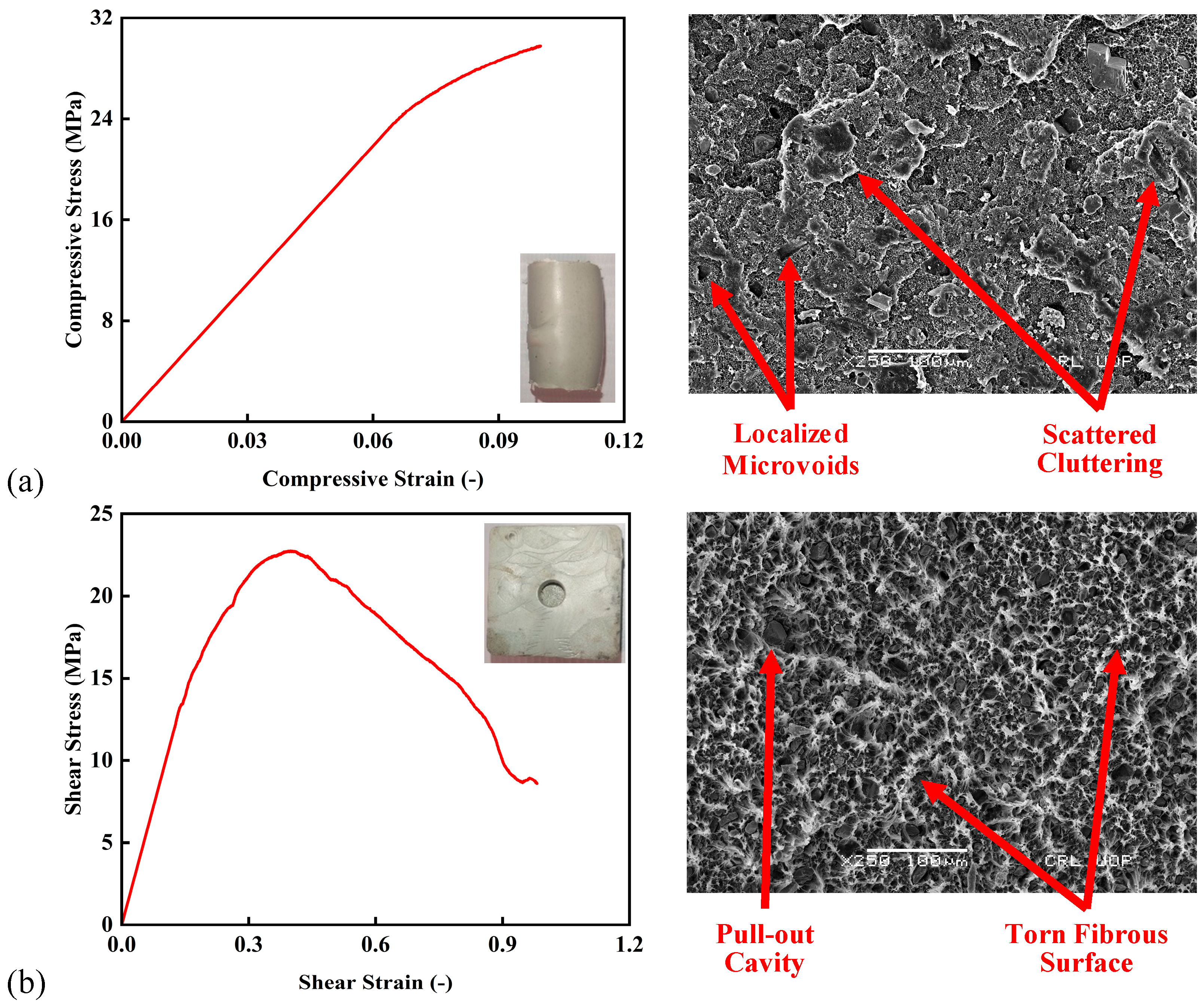
The stress–strain behavior under compression is shown in Figure 2a. Since the sample remained unfractured for an elongated strain, the test result until 10% strain was considered. The test revealed a predominantly ductile response. The stress steadily rose up to a peak of 29.92 MPa at around 0.10 strain, without a distinct yield point. This continuous stress increase suggests that the material undergoes gradual plastic deformation, rather than experiencing brittle fracture. The microstructural evidence further supports this observation, showcasing localized microvoids and scattered cluttering, which are indicative of plastic deformation mechanisms such as void nucleation and polymer chain sliding. These findings confirm that under compressive loading, rHDPE maintains its structural integrity and effectively absorbs energy through ductile deformation, with the sample bulging up to 125% in an outward direction. Similarly, the stress–strain behavior under shear loading is presented in Figure 2b. The shear stress–strain curve peaks at 21.77 MPa around 0.41 strain, followed by noticeable characteristic shear banding, indicating strain softening and post-peak damage. This behavior points to a combination of ductile and brittle failure modes. The SEM image provides further insights, revealing microfibrillation and torn fibrous surfaces, which are characteristic of shear failure induced through microfibril stretching and material tearing. These observations suggest that while rHDPE can exhibit ductility under shear loading, it is more susceptible to localized damage and weakening compared to its performance under compressive loading.
The compressive and shear testing results are presented in Table 1. The compressive strengths are shown in Megapascals (MPa), energy absorptions are shown in Megajoules per cubic meter (MJ/m3), and the toughness index is a unitless ratio of the total energy and pre-peak-load energy. Under compressive loading, the rHDPE specimen exhibited a peak stress of approximately 29.92 MPa at a corresponding strain of 0.10. This indicates strong resistance to deformation under axial loading. The energy absorption prior to the peak was 1.83 MJ/m3, with no notable post-peak energy absorption, confirming a stable ductile deformation mode without sudden material collapse. The toughness index, a measure of post-peak ductility, was 1.00, reflecting minimal softening or energy absorption beyond the peak load. These characteristics align with the microstructural assessment, which showed localized microvoids and scattered surface cluttering, signifying uniform plastic deformation and high compressive integrity. In contrast, the shear response of the rHDPE exhibited a lower peak stress of 21.77 MPa but a much higher strain at failure (0.41), reflecting the material’s capacity for significant plastic deformation under lateral loading. The energy absorption was higher, with a pre-peak value of 5.88 MJ/m3 and a post-peak value of 9.80 MJ/m3, resulting in a total absorbed energy value of 15.67 MJ/m3. The toughness index of 2.67 indicates substantial post-peak ductility, revealing that rHDPE not only resists shear forces but continues to absorb energy after peak stress through mechanisms such as fibril pull-out and surface tearing, as observed in the microstructural assessment. The obtained material properties of rHDPE represent appropriate strength characteristics in comparison to conventional materials used in the construction industry.

2.2. Design and Manufacturing of IHBs

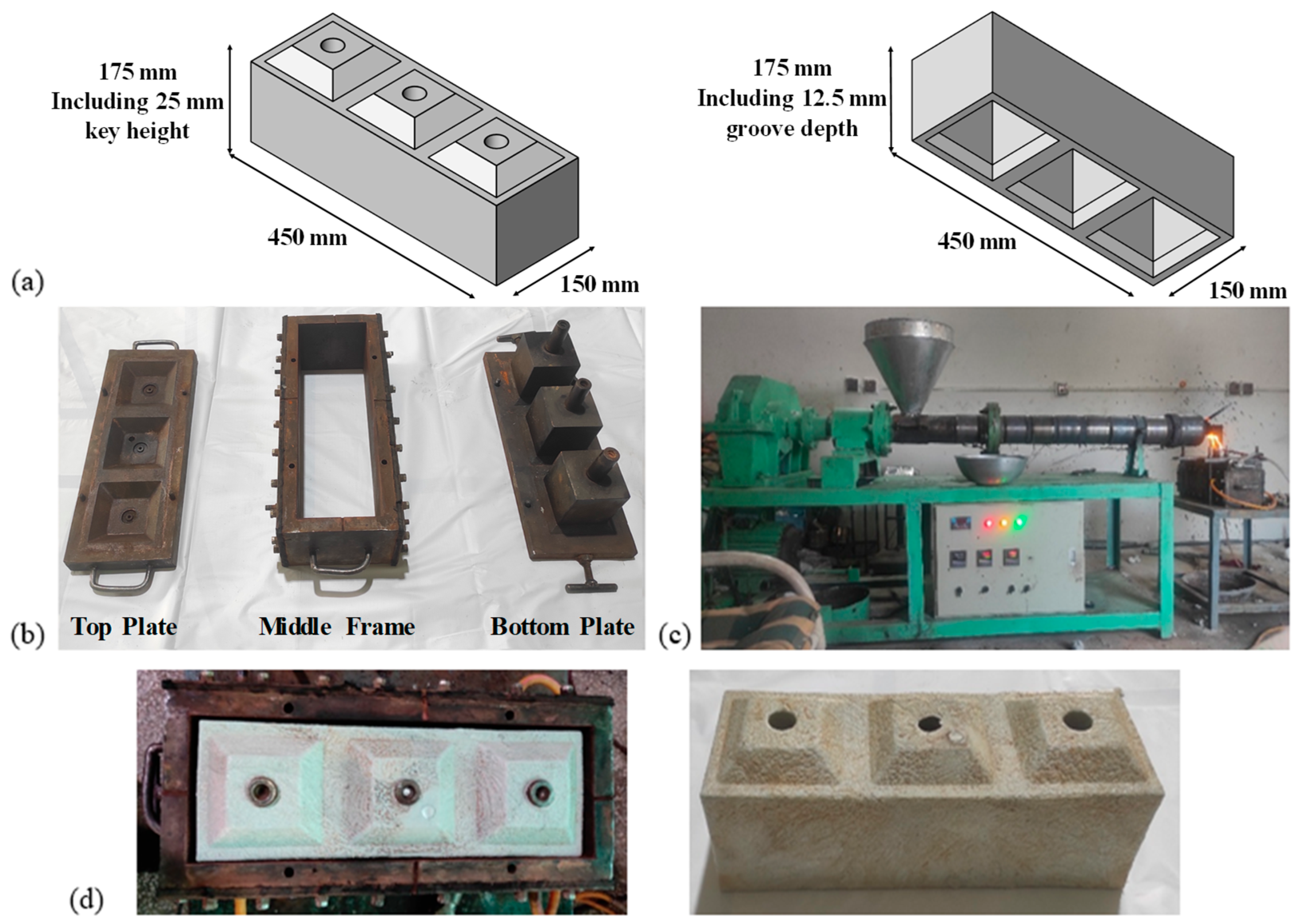
An innovative interlocking hollow block was devised with a triple-unit strategy, keeping in mind the continuity requirements of block layer connections at wall corners and junctions. The block dimensions were selected based on several key considerations, including a balance between ease of handling and limiting the number of blocks required for a particular project, the optimal space for hollowness, adequate thickness for block peripheries, and the sizes of hollow concrete blocks available in the industry. The block dimensions are 450 mm × 175 mm × 150 mm, with a periphery wall thickness of 25 mm and an internal wall thickness of 50 mm. A hollowness of 39.5% is attributed to this design, and it has the ability to incorporate reinforcing bars and conduiting through cylindrical holes with diameters of 31.25 mm, as well as the benefit of a self-centering mechanism using interlocking keys and grooves. Square keys with heights of 25 mm are provided on the tops of blocks with top planar dimensions of 75 mm × 75 mm and bottom planar dimensions of 125 mm × 125 mm. Contrary to that, 12.5 mm deep square grooves are provided on the bottoms of blocks with top planar dimensions of 100 mm × 100 mm and bottom planar dimensions of 125 mm × 125 mm. The linear contact length between the groove of the upper-layer block and the key of the lower-layer block is maintained at 17.2 mm, providing 17.2 mm of room to exercise the self-centering ability in cases of in-plane and out-of-plane movement. This pre-allowed tolerance makes this IHB innovative.
Figure 3a shows the shape of an interlocking hollow block, referred to as a triple-unit standard (TUS) block. The double-unit standard (DUS) block and single-unit standard (SUS) block have reduced lengths of 300 mm and 150 mm, respectively. By removing the top keys from the triple-unit, double-unit, and single-unit standard blocks, the height of the IHB is reduced to 150 mm, providing blocks named the triple-unit top (TUT) block, double-unit top (DUT) block, and single-unit top (SUT) block, respectively. Based on the shapes of the blocks and the nature of the pressurized filling process, a specially designed mold was manufactured to ensure production of blocks with surface uniformity and quality edges. The mold comprised a bottom plate, a periphery wall, and a top plate that were laid over each other and locked using insertion keys. The three components of the mold are presented in Figure 3b. As the operating temperature of the plastic extrusion was nearly 250 °C, the mold was accompanied by an attached water body to facilitate the cooling process after complete filling. The mold was attached to the outlet of the extruder with an accompanying nozzle to be filled at a screw speed of 47 rpm. The mold was firmly clamped to a bench in order to ensure the plates had a close fit during pressurized filling. The manufacturing setup is shown in Figure 3c. Due to the inherent nature of the material, a dimensional decrease of up to 2.7% was witnessed due to post-cooling shrinkage of the plastic. A manufactured block is shown in Figure 3d. In order to measure water absorption, a dry IHB was weighed and immersed in water for 24 h as per ASTM D570-22 [62]. The initial weight of the IHB was 15.225 ± 0.275 lbs. The final weight obtained after removing the IHB from the water and immediate drying was 15.280 ± 0.300 lbs, resulting in a water absorption value of 5.5%. This relatively low water absorption indicates that the IHBs have good resistance to water ingress. The low absorption rate of the IHBs suggests that the blocks will maintain their structural integrity and durability under typical weather conditions, making them suitable for use in external walls, where moisture resistance is critical. However, prolonged exposure to water could still affect the performance of the IHBs. Thus, a detailed durability study will be required in the future to assess their water absorption behavior over longer periods. A total of eight IHB configurations were considered for experimental work. Three IHB configurations had both keys and grooves and had lengths of 150 mm, 300 mm, and 450 mm, making them single-unit, double-unit, and triple-unit standard blocks, respectively. Three IHB configurations had only grooves, with similar variation in their lengths, making them single-unit, double-unit, and triple-unit top blocks. The two remaining IHB configurations were a standard prism with three standard IHBs stacked on each other and a top prism with one top IHB stacked on two standard IHBs. Table 2 shows the block configurations accompanied by the intended tests.

2.3. Dynamic Testing of IHBs

The dynamic properties of the IHBs were investigated using an impulse excitation of vibration method as per ASTM E1876-22 [63] using a Model RT-I Resonance Tester acquired from Olson Instruments Inc., Wheat Ridge, CO, USA. The RT-1 comes with software that generates a spreadsheet of test data, including frequencies and dynamic moduli. Equations (1) and (2) show the procedure to determine the dynamic modulus of elasticity ( E d y n ) and the dynamic modulus of rigidity ( R d y n ), where L is the length of the IHB, f is the frequency of the relevant mode, ρ is the density, and T is the correction factor. Considering the complex nature of the hollow block shape, four modes of vibration were considered, namely in-plane transverse, out-of-plane transverse, longitudinal, and rotational. The dynamic properties include fundamental resonant frequencies, leading to damping of all four modes and the dynamic moduli of elasticity and rigidity. The half-power bandwidth method was used to obtain damping percentages. Further investigation into the damping coefficient or quality factor was considered outside of the scope of this study and may be investigated later to classify the blocks as underdamped or overdamped systems. This experiment was performed according to ASTM E1876-22, including the support conditions of the samples, the placement of the accelerometer, and the point of impact [63]. The impact force was carefully applied to generate vibration without dislocating the sample from its position. In the case of the in-plane transverse mode, where the point of impact coincided with the cylindrical hole, the average of the fundamental frequencies across both ends of the cylindrical hole was considered. For each mode, the average of two values was taken for two similar block samples. Figure 4 shows the modes of vibration employed during dynamic testing.
E d y n = 4 × L 2 × f l o n g . 2   o r   f t r a n . 2 × ρ × T
R d y n = 16 × L 2 × f r o t . 2 × ρ × T

2.4. Mechanical Testing of IHBs

2.4.1. Compressive Testing of IHBs

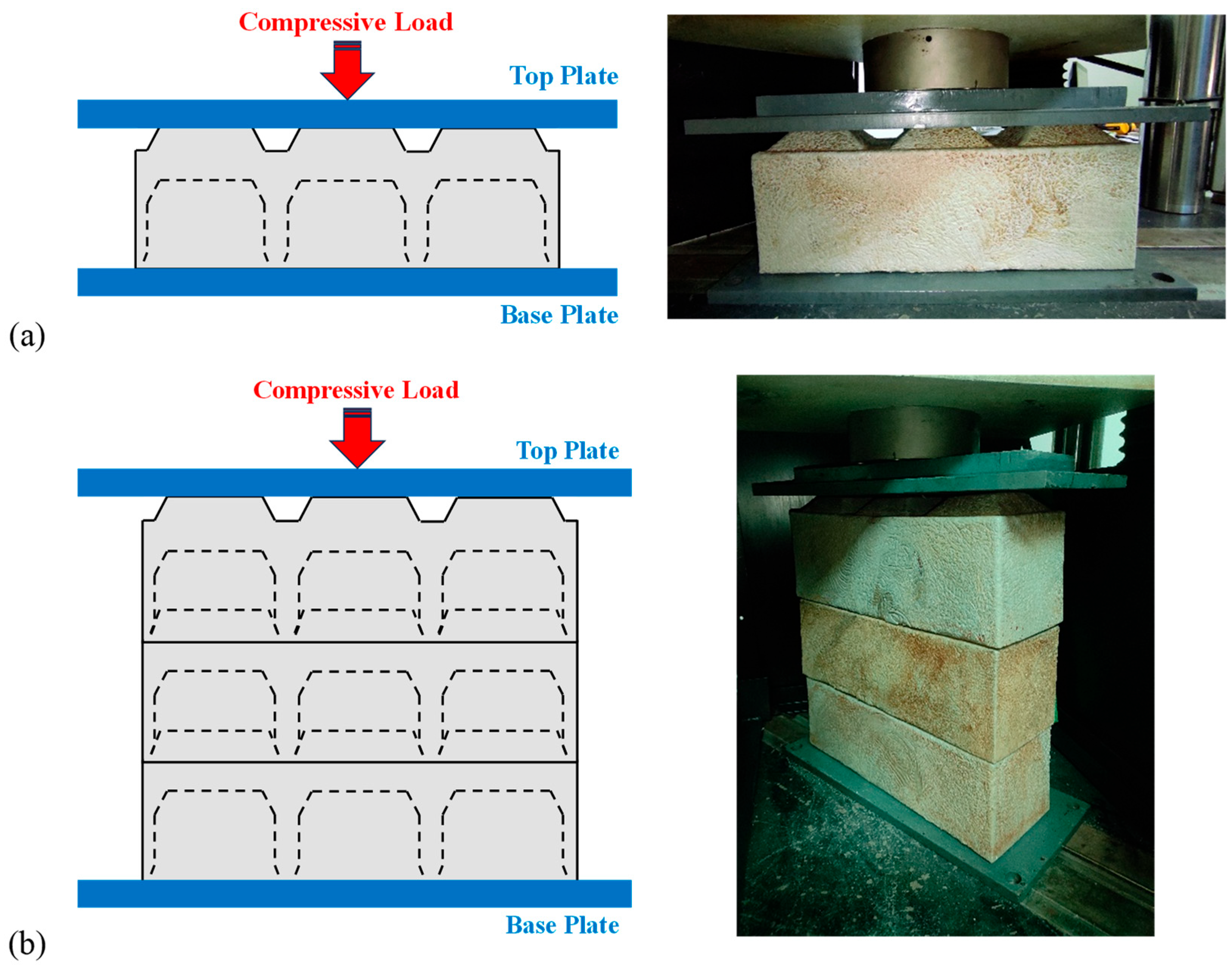
Compressive testing of the IHBs and IHB prisms was conducted as per BS EN 1052-1 [64]. A Servo Hydraulic Testing Machine (IBMU4-2000, acquired from Ibertest, Madrid, Spain) with a maximum load capacity of 2000 kN was used. Its strain gauge load measurement cell had a 5-digit floating-point load resolution with a measurement range from 2% to 100% and cell repeatability of ±0.05%. The data acquisition rate included a displacement resolution of 0.001 mm with a maximum piston displacement speed of 100 mm/min and a maximum crosshead elevation speed of 200 mm/min. Samples were placed between the base plate and a top plate joined to the hydraulic head of the machine. The loading rate applied for compression was 1.3 ± 0.3 mm/min. The stress–strain behavior was obtained from a compressive test, along with observations of the failure modes for all IHB configurations. The stress–strain behavior was then used to calculate the maximum compressive strength (σmax) by dividing the maximum load by the contact area at the top. Additionally, the corresponding strain at the maximum compressive stress (εc) was noted. The pre-peak-load energy absorption (Epre), post-peak-load energy absorption (Epost), and total energy absorption (Etotal) were calculated for all IHB configurations using numerical integration under the stress–strain curve through Simpson’s rule. The toughness index (T. I.) was obtained by taking the ratio of Etotal to Epre. Typical setups for the compressive tests of the IHBs and IHB prisms are presented in Figure 5a,b.

2.4.2. Shear Testing of IHBs

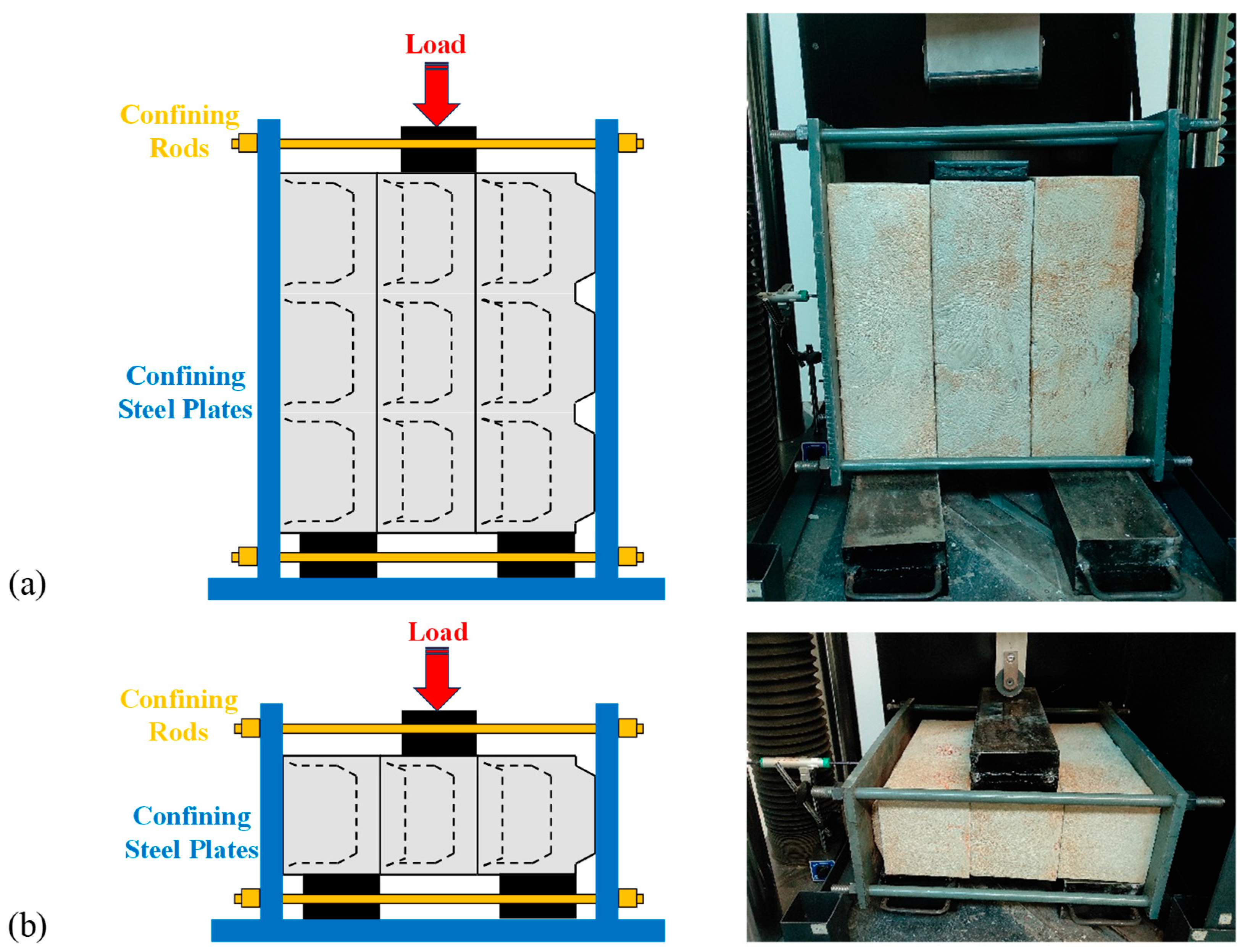
Shear testing of a standard IHB prism in the in-plane (IP) and out-of-plane (OOP) directions was conducted as per BS EN 1052-3 [65]. In the IP shear testing, axial force was applied vertically on the 150 mm × 150 mm planar side of the prism through a solid square steel unit for a uniform load distribution. The prism was placed over two solid rectangular steel sections in a way that allowed the middle block to slide downward in response to load application, and the shear behavior was obtained. Similarly, in the OOP shear testing, axial force was applied vertically on the 450 mm × 150 mm planar side of the prism through a solid rectangular steel section for a uniform load distribution. The supporting mechanism remained similar to the IP shear testing. Steel rods with fastening nuts were used to confine the steel plates. Three pre-compressive stresses (0.2 N/mm2, 0.6 N/mm2, and 1.0 N/mm2) were applied to confine the IHB prisms, as recommended by BS EN 1052-3 [65]. The complete samples were then placed on two solid rectangular steel units such that the middle IHB remained unsupported between the solid steel units for shearing. The loading rate was maintained at 1.3 ± 0.3 mm/min. The stress–strain behavior was obtained from both the IP and OOP shear tests, along with observations of the failure modes. The stress–strain behavior was then used to calculate the maximum shear strength ( τ m a x ) by dividing the maximum load by two times the cross-sectional area parallel to the loading direction, as recommended in BS EN 1052-3 [65]. In addition, the corresponding strain at the maximum shear stress ( ε τ ), E p r e , E p o s t , E t o t a l , and T. I. were calculated for both IP and OOP shear at three confining stresses ( σ c ). Typical setups for testing the IP and OOP shearing of an IHB prism are presented in Figure 6a,b.

2.4.3. Empirical Modeling for Prediction of Shear Strength Using Pre-Compressive Stress

The shear strengths at three confining stress levels were utilized to plot a linear regression curve in order to determine the initial shear strength ( τ i ) of interlocking, which is generally referred to as cohesion. By extending the σ c curve to zero, the corresponding value of the intercept was obtained, which was τ i , and the gradient represented the internal friction angle ( tan α k ). Equation (3) represents the coulomb friction model utilized by [66,67] to estimate the shear strength ( τ ) of dry-joint masonry units.
τ = tan α k × σ c + τ i

2.5. Microstructural and Compositional Evaluation

Scanning electron microscopy (SEM) and energy-dispersive X-ray spectroscopy (EDX) were performed using a scanning electron microscope (JSM5910, made by Jeol, Tokyo, Japan). The samples under consideration were taken from fragments of the IHBs tested against compression, in-plane shear, and out-of-plane shear. First, the samples were thoroughly cleaned, dried, and cut into small sections measuring 5 mm. Then, each sample was mounted on an aluminum stub and coated with a thin gold film to prevent charging effects. Images were captured at a scale of 0.5 μm and a magnification of 30,000×. Elemental mapping was performed to obtain a spectrum, along with elemental weight percentages, atomic percentages, and the presence of compounds.

2.6. Chemical and Thermal Evaluations

To study the effect of mechanical extrusion, chemical and thermal evaluations of pellets and fragments of IHBs were carried out using X-ray diffraction (XRD) analysis and simultaneous thermal analysis (STA). Samples were prepared through fine grinding followed by sieving to obtain a uniform particle size of 50 μ m . Tests were performed using an X-ray diffractometer (JDX-3532, made by Jeol, Japan) with a C u   K α radiation wavelength of 1.5418 Å at a voltage of 40 kV and a current of 30 mA. The 2 θ angle range was maintained from 5° to 80° to capture crystalline peaks, and the step size was maintained at 0.02° to obtain high-resolution data. Thermal analysis was performed simultaneously using a thermal analyzer (ST8000, made by Perkin Elmer, Waltham, MA, USA) in a temperature range of 35 °C to 600 °C with a heating rate of 10 °C per minute. The test was conducted in a nitrogen atmosphere (20 mL/min) to prevent oxidation. Thermogravimetric analysis (TGA) revealed mass loss with respect to the temperature change, and the heat flow characteristics were obtained via differential scanning calorimetry (DSC).

3. Results and Analysis

3.1. Dynamic Properties of IHBs

The frequencies and corresponding damping in the transverse (in plane and out of plane), longitudinal, and rotational modes were obtained, as shown in Table 3. An incremental trend was observed in the transverse frequencies in the in-plane direction as the length of the IHB increased. The transverse frequency increased by 25.9% in the DUS block compared to the SUS block and by 52.5% in the TUS block compared to the DUS block. Similarly, there were increments of 86.4% in the DUT block compared to the SUT block and 63.7% in the TUT block compared to the DUT block. For the transverse frequency in the out-of-plane direction, the TUS block with respect to the SUS and the TUT block with respect to the SUT block followed the same trend. However, the DUS and DUT blocks deviated from this trend with a considerable decrease because the central partition in the IHB with a length of 300 mm coincided with the point of impact. This led to a division of resonance in a parallel direction through the partition and in a perpendicular direction towards the accelerometer. In the longitudinal mode, the highest frequency appeared in the DUS block, followed by the TUS and SUS blocks. A similar trend was observed in the top IHBs. The SUS and SUT blocks revealed the lowest longitudinal frequencies.
However, the presence of one partition in the DUS and DUT blocks acted as a strong reflecting point for the resonance frequency, leading to the highest frequency. Contrary to that, the presence of two partitions led to destructive interference of the propagating wave, ultimately resulting in a decreased frequency received by the accelerometer. In the case of the rotational resonance frequency, an increasing trend was observed as the length of the IHB increased. The trend observed in the frequencies was reciprocated in the damping, with the lowest damping occurring against the highest frequency. Since damping represents the ability to dissipate energy, the highest damping was attained in the SUS and SUT blocks in the in-plane direction. The DUS and DUT blocks revealed the highest out-of-plane damping. In the longitudinal direction, the SUS and SUT blocks had higher damping than the others. Similarly, rotational damping was also higher in the SUS and SUT blocks in comparison to the others.
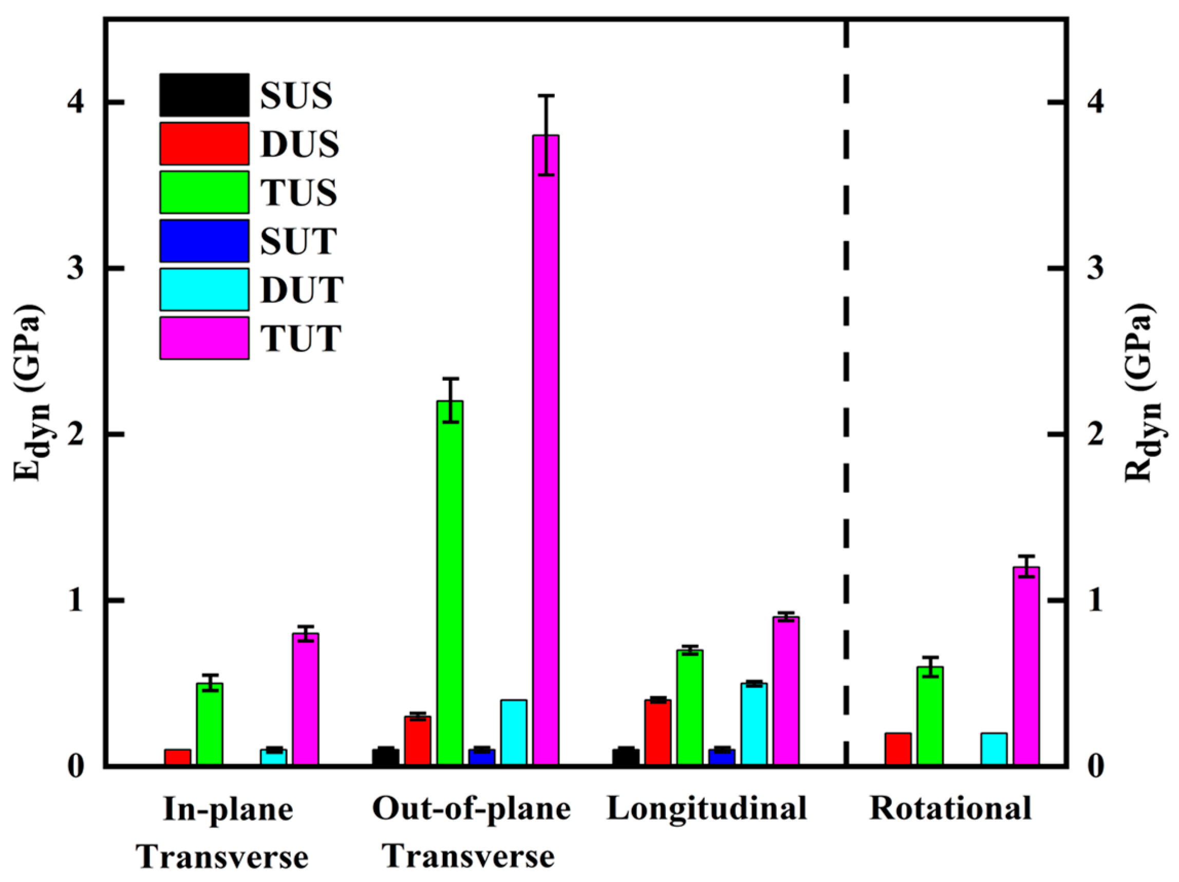
Figure 7 shows the dynamic moduli of elasticity in the transverse and longitudinal directions, along with the dynamic moduli of rigidity in the rotational direction. In the in-plane transverse direction, the TUS block had a modulus of 0.5 GPa, which was 400% greater than the 0.1 GPa of the DUS block. Similarly, the TUT block had a modulus of 0.8 GPa, which was 700% greater than the 0.1 GPa of the DUT block. The SUS and SUT blocks had negligible modulus values. In the out-of-plane transverse direction, the TUS block had a modulus of 2.2 GPa, which was 633% greater than the 0.3 GPa of the DUS block. Similarly, the TUT block had a modulus of 3.8 GPa, which was 850% greater than the 0.4 GPa of the DUT block. The longitudinal dynamic elastic modulus of the TUS block was 0.7 GPa, which was 75% greater than the 0.4 GPa of the DUS block. Similarly, the TUT block had a modulus of 0.9 GPa, which was 80% greater than the 0.5 GPa of the DUT block. The SUS and SUT blocks had elastic moduli of 0.1 GPa in both the out-of-plane transverse and longitudinal directions. In the rotational mode, the dynamic modulus of rigidity of the TUS block was 0.6 GPa, which was 200% greater than the 0.2 GPa of the DUS block. Likewise, the TUT block had a rigidity modulus of 1.2 GPa, which was 500% greater than the 0.2 GPa of the DUT block. The SUS and SUT blocks had negligible values for the dynamic modulus of rigidity. By and large, the obtained dynamic parameters emphasize that mass concentration and stress wave propagation are influenced by the top surface geometry, resulting in varying amounts of vibrational stiffness. IHBs with greater longitudinal dimensions and plain tops have increased dynamic stiffness and exhibit varying damping characteristics that are critical for vibration-sensitive structural applications.

3.2. Mechanical Properties of IHBs

3.2.1. Compressive Strength and Related Parameters of IHBs

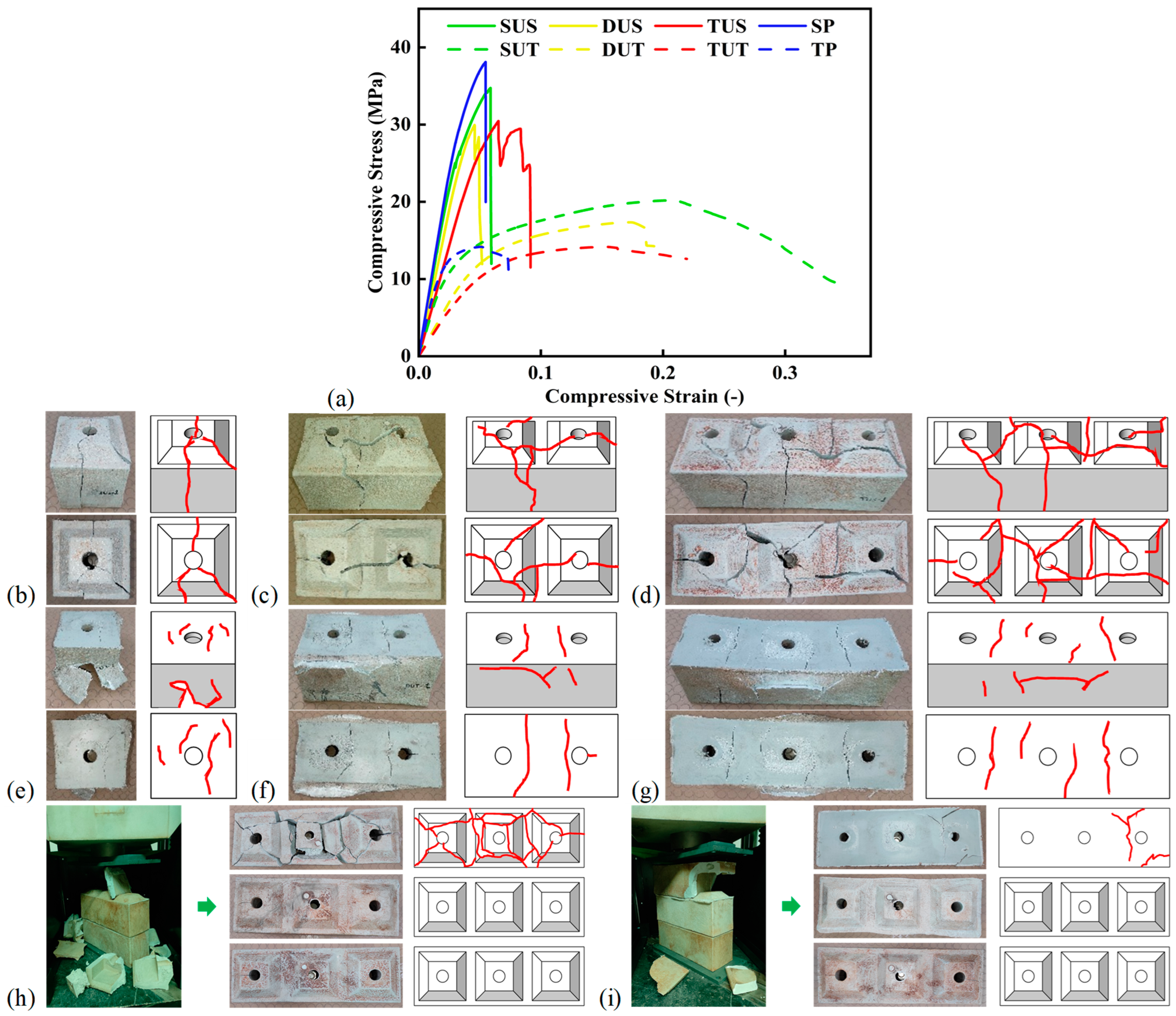
Compressive testing was conducted to obtain load displacement behavior, which was transformed into stress–strain behavior. Figure 8a shows the compressive stress–strain behavior of all samples. It is evident from the behavior that the configurations with standard blocks exhibited greater stress at a low corresponding strain. However, the configurations with top blocks displayed less stress at a high strain, leading to elongated failure. Figure 8b–i show two views of the failed samples to display the crack patterns. Figure 8b shows the failure of the SUS block, which was attributed to two diagonal cracks and one central crack emerging out of the key. Figure 8c shows splitting of the DUS block along almost 60% of the block length, along with a diagonal crack propagating towards the side wall. Similarly, the failed TUS block shows splitting of one and a half keys horizontally, in combination with one central crack and one diagonal crack propagating up to the wall of the block, as shown in Figure 8d. The IHBs with keys at the top predominantly failed diagonally or due to X-shaped shear cracks initiating from concentrating stresses around the circular hollow voids, suggesting brittle fracture modes dominated by shear and tension. In the case of the SUT block, two crack lines appeared at the top, but significant damage coupled with bulging of the walls was witnessed, as shown in Figure 8e. In the case of the DUT block, two crack lines appeared beside the holes, and side walls measuring 300 mm in length bulged out near the top, as shown in Figure 8f. Similarly, Figure 8g displays outward bulging of 450 mm walls in the center and three crack lines on the top surface of the TUT block. The IHBs with plain top surfaces exhibited relatively localized vertical and horizontal cracks around the circular hollow voids and centerline, which align with more gradual degradation and energy absorption. In the case of the SP, the two bottom blocks remained undamaged. However, the top block failed, with excessive cracks propagating diagonally outward from the keys, as shown in Figure 8h. Contrary to that, the TP exhibited cracking on top and separation of one-third of the top block. The middle block displayed outward expansion of the surface layer, and the lower block remained undamaged, as shown in Figure 8i. In all tests, the standard IHBs exhibited brittle failure with rapid outward projection of fragments, whereas the top IHBs revealed ductile failure with gradual cracking and disintegration.
The parameters obtained from the compressive testing are shown in Table 4. The maximum compressive strength of the SUS block was 35.75 MPa, which was 6.4% greater than the 33.61 MPa of the DUS block, which was 8.5% greater than the 30.99 MPa of the TUS block. The reciprocating trend in the corresponding strain was observed, with the SUS block having a smaller value and the TUS block having a greater value. In the case of the static elastic modulus, a similar trend was observed, with the highest values being 616.38 MPa in the SUS block and 744.13 MPa in the SP. The pre-peak-load energy absorption was greater in the DUS block, followed by the SUS and TUS blocks. After combining the post-peak-load energy absorption, the total energy absorbed by the DUS block was 1.56 MJ/m3, followed by 1.42 MJ/m3 for the SUS block and 1.27 MJ/m3 for the TUS block. The toughness index showed a better response in the TUS block at 1.23, followed by 1.18 for the DUS block (a 4.1% decrease) and 1.10 for the SUS block (a further 6.8% decrease). Two prisms (standard and top) with three stacked blocks were also tested, and the results revealed a compressive strength of 34.23 MPa for the SP, which was 177% greater than the 12.34 MPa of the TP. However, the corresponding strain of the SP was 0.046 compared to 0.053 for the TP. The pre-peak-load energy absorption was greater in the SP in comparison to the TP. However, the post-peak-load energy absorption was negligible in the case of the SP. The total energy absorption values for the SP and TP were 0.92 MJ/m3 and 0.62 MJ/m3, respectively. The toughness index of the TP was 1.36, which was 34.7% greater than the 1.01 of the SP. The compressive strength of gypsum-based concrete blocks is up to 32.6 MPa [68]. The compressive strength of recycled construction waste blocks is up to 46.70 MPa [69], while that of red mud-based green bricks is up to 20.3 MPa [70]. These blocks may be considered sustainable alternatives to conventional blocks. However, valorized furnace slag from gypsum-based concrete blocks, silica fumes from recycled construction waste blocks, and chemical processing of red mud-based green bricks make their manufacturing a concern from the points of view of ease and economics. The compressive strength of conventional hollow concrete blocks ranges from 8.9 MPa to 45.6 MPa, and they are either used for non-load-bearing structures (lightweight concrete blocks) or load-bearing structures. The concrete used in manufacturing these blocks has a compressive strength ranging from 3.65 MPa to 26.90 MPa [71]. When comparing these conventionally used materials and products, the 29.92 MPa compressive strength of rHDPE and 30.99 MPa compressive strength of IHBs made from rHDPE seem to have better performance considering the prominent advantage of only using a waste material. Also, the obtained compressive results are far greater or comparable to the masonry strength requirements in applicable building codes. For clay masonry units, BS EN 771-1 [72] specifies a net compressive range of 5 MPa to 50 MPa, whereas for masonry, compressive strength ranges from 2.5 MPa to 6 MPa, as per BS 5628-1 [73].

3.2.2. Shear Strength and Related Parameters of IHBs

The shear stress–strain behavior was obtained from the load displacement data from the shear testing. Figure 9a shows the shear stress–strain behavior in both directions against three σ c values. The presence of shear keys in series led to a greater load-carrying capacity and corresponding strength in the in-plane direction. However, a lower load-carrying capacity and corresponding strength was attributed to the parallel arrangement of shear keys in the out-of-plane direction. It is pertinent to highlight that despite a lower load-carrying capacity, delayed failure contributed to a greater energy absorption capacity in the out-of-plane direction. Figure 9b shows a post-test damaged sample from in-plane shear testing. In-plane shear testing revealed sliding of the middle IHB, followed by brittle splitting of the right IHB, which explicitly validated the greater sliding strength of the middle IHB keys against the sliding shear resistance of the right IHB grooves. Due to the in-plane shear force applied by the shear keys of the middle block, the right block split along up to 80% of its length. However, the middle block only had a rupture in its wall due to the punching of the steel loading plate. The left block, with its shear keys inserted in the grooves of the middle block, did not show any failure. In contrast, out-of-plane shear testing uncovered ductile failure by sliding the middle IHB keys to initiate flexural failure in the right IHB grooves. The right block had a corner wall disintegrate due to the shear force exerted by the shear key of the middle block. However, the middle block did not exhibit any failure except for some roughness at the points of contact. The left block remained undamaged, as shown in Figure 9c. In-plane shear consistently yielded higher peak stresses and steeper stress–strain curves compared to out-of-plane shear. As the maximum stress was reached, the IHBs underwent progressive cracking and structural degradation, leading to declines in their load-bearing capabilities. The out-of-plane shear behavior displayed a more gradual slope and lower stress levels across all pre-compressive stresses. This suggests that the interfacial cohesion and stiffness within the keys and grooves of the IHBs were lower in the out-of-plane direction, making them more susceptible to shear failure in that orientation.
The parameters obtained from the shear testing are shown in Table 5. The maximum shear strengths in the in-plane direction were 2.09 MPa, 2.30 MPa, and 2.44 MPa for three σ c values. However, in the out-of-plane direction, the maximum shear strengths were 1.51 MPa, 1.56 MPa, and 1.66 MPa for three σ c values. The difference between the in-plane and out-of-plane shear strength is supported by the fact that the centroidal axis of all shear keys lay on the centroidal axis of the block in the case of in-plane shear in comparison to the out-of-plane direction. The highest corresponding strain was observed for the moderate σ c , followed by the greater σ c and the smaller σ c . The pre-peak-load and post-peak-load energy absorption showed an increasing trend as the σ c increased. The total energy absorption in the out-of-plane direction was greater than that in the in-plane direction. The total energy absorption in the out-of-plane direction reached 0.15 MJ/m3, compared to 0.12 MJ/m3 in the in-plane direction, for the maximum σ c value. Similarly, the toughness index in the out-of-plane direction reached 1.35 for the maximum σ c value. But a decreasing trend was revealed for the toughness index in the in-plane direction with an increase in σ c . This difference was attributed to similar post-peak energy absorption for all σ c values. Considering the simplified shape of the clay bricks and hollow concrete blocks currently used in the construction industry, they possess negligible lateral resistance, which necessitates using mortar and bed joints. However, the interlocking shape of the IHBs overcomes the lateral resistive requirement, as the interlocking mechanism eliminates the need for mortar.

3.2.3. Correlation Between Shear Strength and Pre-Compressive Stress

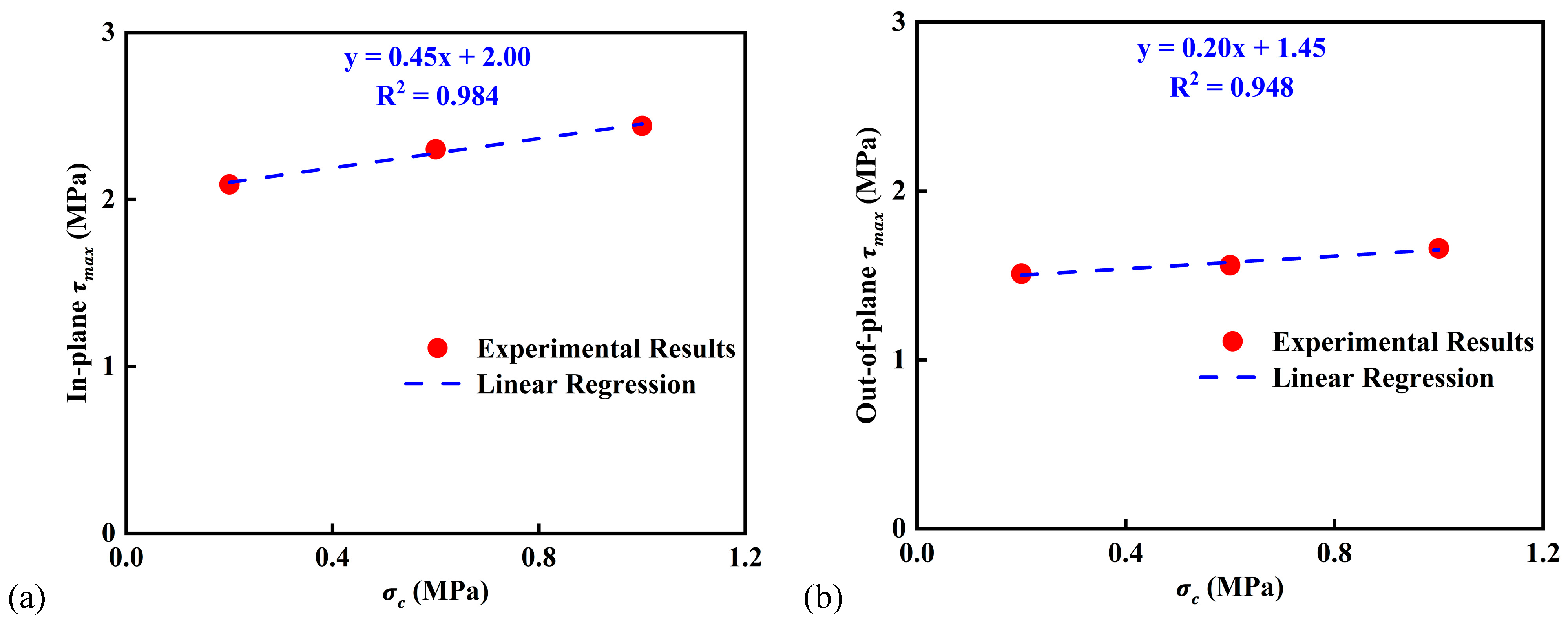
Since the compressive strength of the IHBs was more than 10 MPa, three pre-compressive stresses (0.2 N/mm2, 0.6 N/mm2, and 1.0 N/mm2) were selected to obtain corresponding shear strengths. Figure 10 shows the relationship between pre-compressive stress and shear strength in both the in-plane and out-of-plane directions. The line representing the linear regression corresponds to the initial shear strength ( τ i ), which is 2.00 MPa and 1.45 MPa in the in-plane and out-of-plane directions, respectively. This initial shear strength is attributed to the interlocking effect of the shear keys, which remains zero in the case of dry stacked masonry. The internal friction angle ( tan α k ) gives a value of one in both cases, as α k is 45°. To simplify the empirical equation, a shear key factor ( K s ) is introduced that can be taken as 0.45 and 0.20 for the in-plane and out-of-plane directions, showing a greater value when the centroidal axes of the shear keys are collinear and a lesser value when the centroidal axes of the shear keys lie parallel to each other. By replacing the values of tan α k and τ i in Equation (3), in-plane and out-of-plane shear strengths can be calculated for any pre-compressive loads ( σ c ). Given the applied pre-compressive stresses and the initial shear strength of the IHBs, the shear strength can be obtained from Equation (4) with accuracy of values upto 98.4% and 94.8% for the in-plane and out-of-plane directions, respectively.
τ = K s tan α k × σ c + τ i
Table 6 displays actual shear strengths from experimental testing and predicted shear strengths obtained from developed equations. The absolute percentage difference lies below 1.32%, which indicates that the equations are accurate. In the case of in-plane shear, an accurate prediction was obtained in the low stress range. However, slight under-estimation was noticed in the medium stress range. In the higher stress range, negligible over-estimation was observed. For out-of-plane shear, the accuracy of the equation was inversely proportional to the stress range. In the lower stress range, the largest percentage difference was obtained, while the error decreased as the confining stress increased.

3.3. Microstructural Analysis and Distribution of Elemental Composition

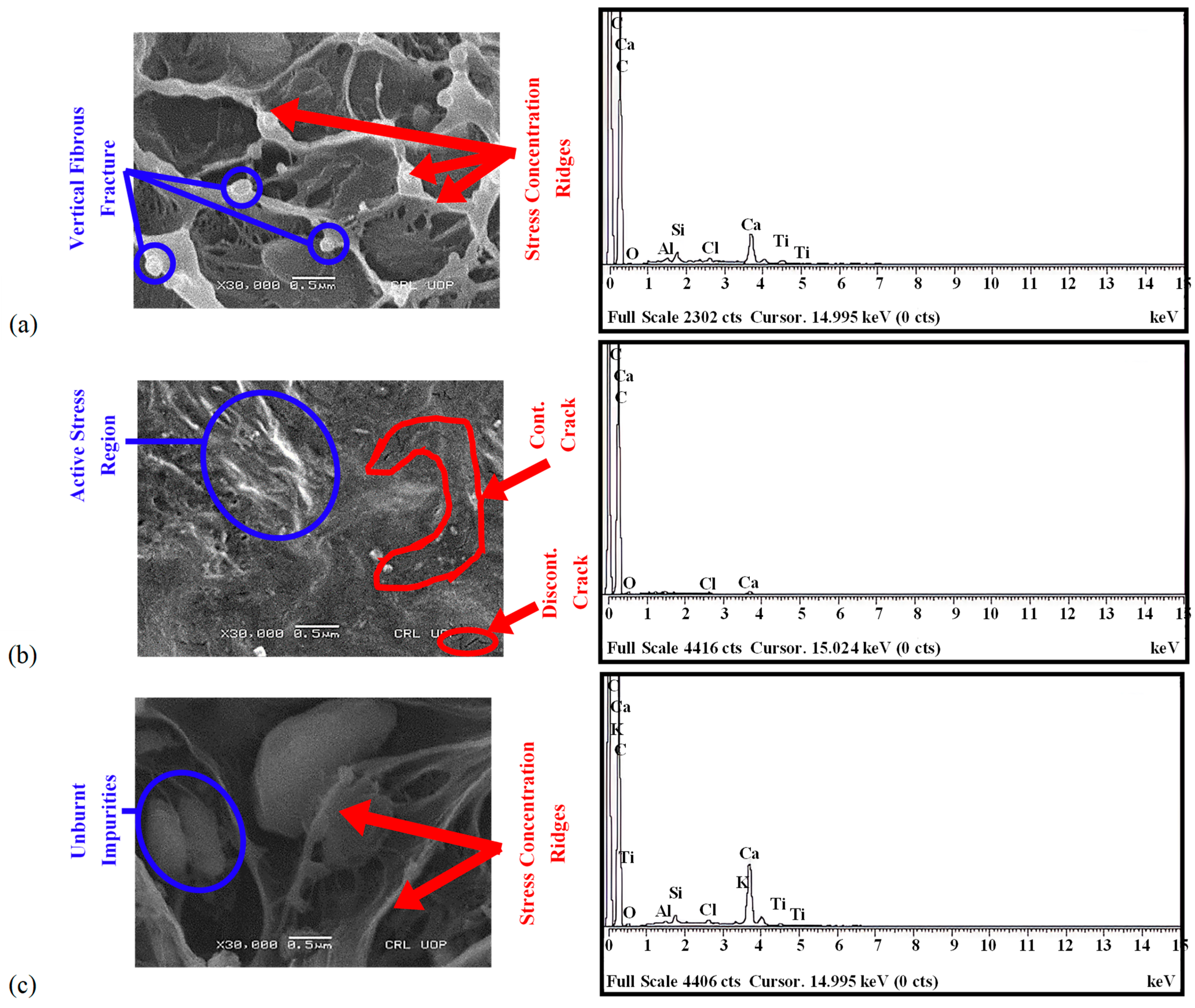
The surface morphology and elemental spectrum of the sample tested against compression are shown in Figure 11a. Since the applied compressive load resulted in transverse-dominated failure, the slip generated in the transverse direction led to excessive fibrous damage. This damage led to the formation of numerous stress concentration zones, shown as bright ridges, which indicates that the fibrous surface had greater participation against applied stresses. The broken surfaces of vertical fibers also validate the surface fracture of the sample. The energy-dispersive spectrum shows strong peaks of carbon and calcium with traces of impurities like silica, chlorine, aluminum, and titanium. Due to the development of in-plane stresses, slip was generated on the plane where a continuous fibrous chain existed in the longitudinal direction, as shown in Figure 11b. This led to splitting failure in the IHB, as shown in Figure 9b. Shorter cracks are also visible at the locations of discontinuous fibrous chains. The limited stress regions concentrated at particular locations identify the non-homogeneity of the sample, which led to unequal surface participation against stresses. The spectrum shows strong peaks of carbon and calcium with limited presence of impurities like chlorine. The out-of-plane load caused longitudinal failure in the IHB, resulting in deep damage with limited stress concentration zones, as shown in Figure 11c. In addition, during extrusion unburnt particles were also enclosed within the dips representing impurities of stable compounds. Peaks of carbon and calcium are evident, and traces of impurities like potassium, silica, chlorine, aluminum, and titanium are also present. The strong peak of carbon confirms the hydrocarbon chain of rHDPE.
The elemental compositions of rHDPE samples from fragments of fractured blocks tested against compression, in-plane shear, and out-of-plane shear are shown in Table 7. The presence of calcite (CaCO3) remains highest, with 87.95%, 94.36%, and 79.05% mass compositions in the compression-tested, in-plane shear-tested, and out-of-plane shear-tested block samples. The presence of quartz (SiO2) and wollastonite (CaSiO3) corresponds to the presence of traces of additives and fillers in the rHDPE plastic. The presence of alumina (Al2O3), potassium feldspar (KAlSi3O8), and potassium chloride (KCl) indicates the presence of contaminants due to the recycled nature of the waste plastic. Titanium oxide (TiO2) is an additive that is typically used as a pigment for whitening plastic during recycling. It is evident from the analysis that the majority of the mass is composed of carbon and oxygen, indicating that the hydrocarbon and limited amounts of additives, fillers, and contaminants are present, which is related to slightly compromised sorting.

3.4. Chemical Characterization and Thermal Analysis

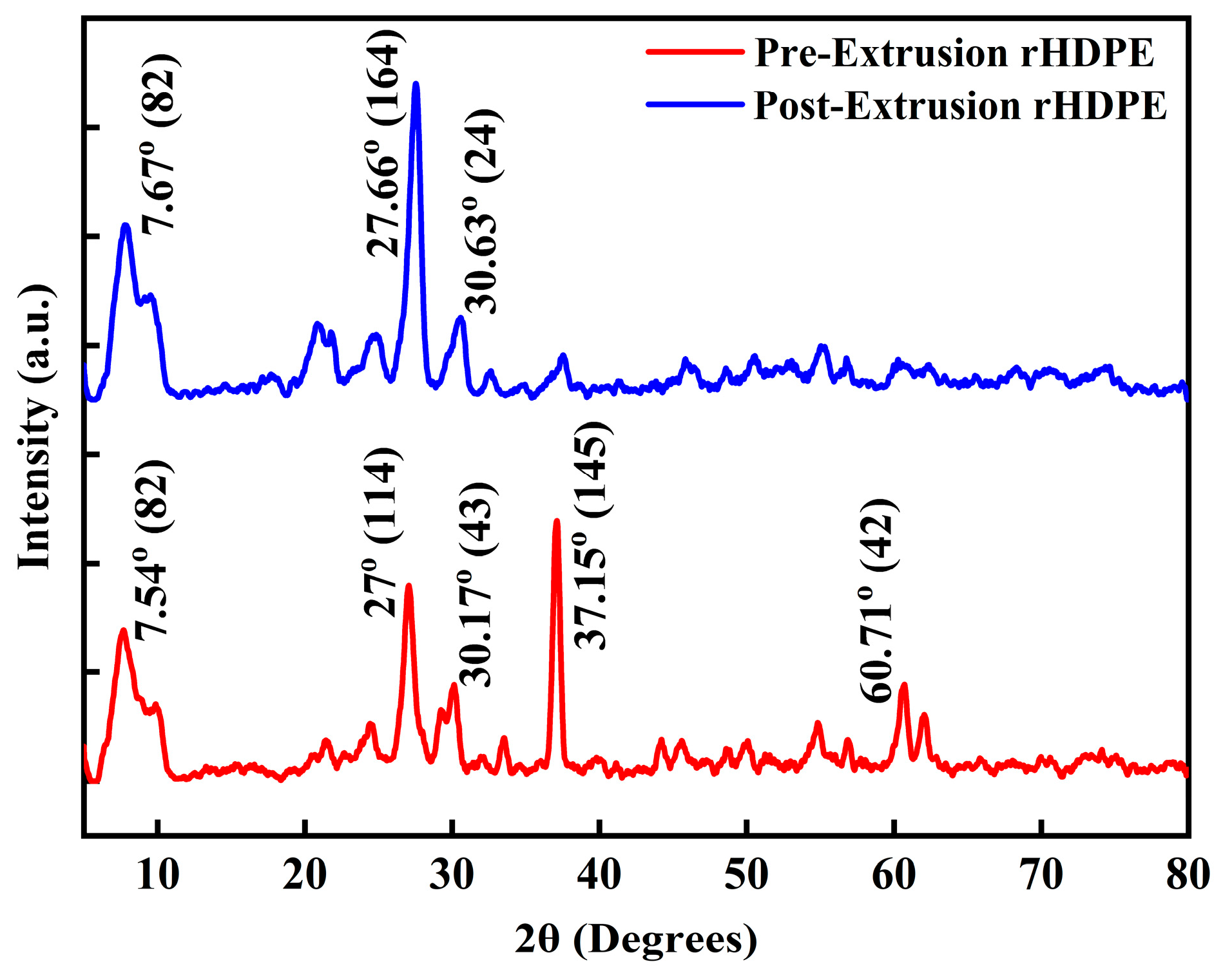
The XRD analysis of pre-extrusion and post-extrusion rHDPE samples is shown in Figure 12. Since the pellets were produced through extrusion, this comparison corresponds to the second extrusion cycle. The low-angle peak intensity of 82 at 7.54° in the pre-extrusion rHDPE indicates the presence of CaSiO3, which also happened to be thermally stable and inert during reprocessing, as its peak intensity of 82 remained unchanged at 7.67° in the post-extrusion rHDPE. At 27°, a peak intensity of 114 was witnessed in the pre-extrusion rHDPE, which matched the peak intensity of 110 of the HDPE after the interference of CaCO3 and SiO2, which have peaks close to 26–27°. In the case of the post-extrusion rHDPE, a greater peak intensity of 164 at 27.66° shows enhanced crystallinity and agglomeration of quartz due to shear-induced alignment during extrusion. The mechanical shear and thermal energy imparted during extrusion can mobilize polymer chains, facilitating their alignment into more ordered regions, thus increasing crystallinity. The peak intensity of 43 at 30.17° corresponds to the peak intensity of 200 of the HDPE, which may have decreased during the process of converting waste HDPE to rHDPE and further decreased in the post-extrusion rHDPE to reach a peak intensity of 24 at 30.63°, implying degradation of the HDPE 200 plane. The specific drop in the intensity also suggests disruption of specific crystalline planes, likely due to thermal stress and oxidative degradation during reprocessing. The shift in the peak position from 30.17° to 30.63° may also indicate lattice distortion or strain within the crystalline domains, possibly arising from interfacial interactions with inorganic fillers such as CaCO3 and SiO2. The peak intensity of 145 at 37.15° corresponds to probable chain reorientation and melting of Al2O3 and KCl during extrusion, resulting in the omission of peaks in the post-extrusion phase, which indicates that these phases are unstable under extrusion conditions. The peak intensity of 42 at 60.71° may align with the higher-order HDPE peaks, which remain in the pre-extrusion phase but are significantly diminished or undetectable post-extrusion. This implies selective degradation of well-ordered crystalline domains, likely due to polymer chain scission and decreased long-range order. In summary, the obtained results suggest that extrusion enhanced crystallinity but degraded crystalline regions. The presence of silica and calcium carbonate masked the HDPE peaks, whereas alumina and potassium chloride proved to be unstable due to melting.
The STA of the pre-extrusion and post-extrusion rHDPE samples is shown in Figure 13a,b. In the case of the pre-extrusion sample, from 35 °C to 233.5 °C, no major degradation occurred except for 4% weight loss, which corresponded to moisture evaporation and loss of any volatile additives. Afterward, polymer degradation was witnessed from 233.5 °C to 403.7 °C, resulting in 17% weight loss due to polymer backbone decomposition, where cleavage of weak chain ends and side groups occurred. This was followed by rapid weight loss of around 71% due to hydrocarbon chain degradation. Subsequently, residual traces of compounds decomposed, causing further weight loss of 7–8% due to residual filler breakdown and combustion of carbonaceous char. The DSC analysis shows oxidative decomposition at 128 °C, followed by melting and evaporation at 231.8 °C. Continuous energy release was witnessed from 231.8 °C to 402.6 °C, after which elemental breathing was noted due to an increase in the surface area of the liquefied sample. A strong endothermic phenomenon emerged, indicating valorization of disintegrated hydrocarbons, until 479 °C, followed by an exothermic shift, probably due to oxidation of residues. Likewise, similar behavior was observed in the post-extrusion sample, as shown in Figure 13b. However, an endothermic phenomenon at 489.8 °C indicated higher heat flow than in the pre-extrusion sample. This was likely due to an increased enthalpy requirement, leading to degradation of hydrocarbon chains during mechanical extrusion and a change in crystallinity. Both samples indicated thermal stability without any abnormal decomposition trends, but mechanical extrusion altered the crystallinity through shear-induced alignment and introduced thermal–mechanical degradation, which weakened long-chain uniformity. This resulted in compromised thermal stability to a limited extent but greater local energy barriers to degrade.

4. Potential Challenges in Construction of Mortar-Free Interlocking Hollow Block House Made of Recycled Plastic

As a prerequisite, recycling waste plastic requires comprehensive processing, including efficient sorting and thorough cleaning, to obtain recycled plastic pellets from a single source with the fewest traces of impurities. This whole procedure requires a complete processing unit to produce ready-to-use recycled plastic. To manufacture building products from this recycled plastic, an efficient mechanical extrusion setup and specially designed molds for pressurized filling are required as a separate unit. The design of the mold requires consideration of dimensional tolerance and a cooling mechanism to harden the recycled plastic before demolding. After manufacturing, the construction process requires special consideration in the design phase to appropriately reinforce IHB walls and, in particular, the connecting mechanism at wall–foundation joints and wall–roof joints. Furthermore, the design of electrical and plumbing fixtures is essential, considering the provision of hollowness in IHBs. Against gravity loading, IHB walls are expected to perform better in light of the obtained compressive strength results. In the case of lateral loading, the obtained shear strength, along with wall reinforcement, can provide appropriate resistance to lateral displacement, with the ability to offer ductile behavior through the self-centering of IHBs. Structurally, IHBs offer enhanced seismic resistance and stability due to their interlocking design, whereas conventional brick or concrete walls are more prone to failure under lateral forces. In terms of thermal performance, IHBs provide better insulation, reducing heat transfer and improving energy efficiency, while traditional systems often require additional insulation materials. Economically, IHBs are cost-effective, as they reduce both material and labor costs through quicker assembly and the use of locally available, often recycled materials. Conventional systems, on the other hand, tend to be more labor-intensive and expensive due to the need for mortar and longer construction times. However, the implementation of IHBs also presents practical challenges. The fabrication process can be hindered by the availability and quality of raw materials like HDPE, and inconsistent mold designs can lead to variations in the strength and dimensions of the blocks. Additionally, while the interlocking mechanism simplifies assembly, precise alignment is crucial in the early stages. Despite these challenges, with improvements in fabrication processes, IHBs present a promising alternative to traditional construction methods.
When subjected to high temperatures, IHB units in walls may undergo plastic softening and thermal expansion, as indicated by the DSC curve, due to loss of structural integrity beyond 300 °C. This can be avoided by adding heat-resistant additives during the production of blocks or a heat-resistant finish coating after manufacturing. At lower temperatures, IHBs may experience contraction, leading to brittle cracking, which impacts the interlocking design. However, such crucial aspects, like UV exposure and temperature variation effects, can be studied in the future to determine the durability in varying conditions. The effect on the internal environment may be minimal due to the hollowness of the IHBs. From an execution standpoint, construction requires less skilled labor compared to conventional masonry construction. In terms of an economic comparison with clay bricks and concrete blocks, the cost of acquiring and recycling waste plastic to manufacture IHBs may exceed the costs associated with clay and concrete. However, combined with the environmental effects of cement production for concrete blocks and the resources required to manage waste plastic, recycled plastic IHBs may dominate as a sustainable alternative to conventional masonry units. Further investigations from a detailed perspective will help in understanding the future implications.

5. Conclusions

Considering the limited use of recycled plastic in construction, this study aimed to evaluate the potential of IHBs made from recycled plastic for mortar-free housing. This was accomplished by investigating their dynamic, mechanical, and physicochemical properties in relation to the prominent stresses that IHBs may encounter during their service lives. In essence, this study provides a foundation for relying on recycled resources and preserving the natural resources used in construction. The following conclusions have been drawn from this study:
  • The damping capacities in the in-plane transverse, longitudinal, and rotational directions increase with an increase in the longitudinal dimension. The highest damping value of 29.9% was observed in the SUT block in the in-plane transverse direction, and the lowest damping value of 3.3% was observed in the TUS block in the out-of-plane transverse direction. The novel shape of the IHBs, with hollow sections within the blocks, helps dissipate energy.
  • The compressive and shear strengths are directly influenced by the shapes of the IHBs. The blocks and prisms with shear keys at the top exhibited greater compressive strength compared to the blocks with plain top surfaces. The shear strengths for different pre-compressive stresses revealed greater strength in the in-plane direction ranging from 2.09 MPa to 2.44 MPa, compared to the strength in the out-of-plane direction ranging from 1.51 MPa to 1.66 MPa.
  • The microstructural analysis revealed strong resistance of fibrous polymer chains against stresses, which resulted in active stress regions. Also, the cracks propagated over continuous fiber paths, leading to splitting of the IHB surface. The presence of unburnt particles confirmed the presence of impurities, as witnessed in the elemental composition, which was attributed to the recycled nature of waste plastic.
  • The chemical characterization revealed omission of peaks of impurities, variation in crystallinity, and degradation of crystalline regions due to the extrusion process. The thermal behavior of rHDPE shows a slight stability reduction in post-extrusion rHDPE. However, there seems to be no abrupt mass loss behavior, which makes it thermally stable. The heat flow behavior suggests strong endothermic and exothermic reactions at high temperatures with limited deviations in pre-extrusion and post-extrusion behavior.
The obtained results indicate that rHDPE can be used reliably in construction products, which promotes resource efficiency by using waste material. rHDPE also displays better characteristics compared to conventional construction materials. Future research should focus on modifying the mechanical characteristics of IHBs made out of rHDPE, as limited strength requirements are suggested in building codes.

Author Contributions

Conceptualization, S.A.; methodology, S.A. and M.A.; investigation, S.A.; writing—original draft preparation, S.A.; writing—review and editing, M.A.; supervision, M.A. All authors have read and agreed to the published version of the manuscript.

Funding

This research work was sponsored by the Higher Education Commission (HEC) of Pakistan under the National Research Program for Universities (NRPU) (project No. 16643).

Data Availability Statement

The data presented in this article is available.

Acknowledgments

The authors would like to acknowledge Aaroon Joshua Das for his technical and administrative support, Qasim Farooq for developing the block mold, and Asim and Asif for their assistance in manufacturing the blocks. Special thanks to Saeed Akhter for the physical support provided during the handling of heavy samples. The valuable technical assistance from Muhammad Junaid Butt during the lab testing was highly appreciated. The careful review and constructive suggestions from the anonymous reviewers are gratefully acknowledged.

Conflicts of Interest

The authors declare no conflicts of interest.

Abbreviations

The following abbreviations are used in this manuscript:
DSCDifferential Scanning Calorimetry
DUSDouble-Unit Standard
DUTDouble-Unit Top
EDXEnergy-Dispersive X-ray Spectroscopy
HDPEHigh-Density Polyethylene
IHBInterlocking Hollow Block
IPIn-Plane
NSLNatural Surface Level
OOPOut-Of-Plane
rHDPERecycled High-Density Polyethylene
rpmRotations Per Minute
SEMScanning Electron Microscopy
SPStandard Prism
STASimultaneous Thermal Analysis
SUSSingle-Unit Standard
SUTSingle-Unit Top
TGAThermogravimetric Analysis
TPTop Prism
TUSTriple-Unit Standard
TUTTriple-Unit Top
XRDX-ray Diffraction

References

  1. Santos, A.K.; Ferreira, V.M.; Dias, A.C. Promoting decarbonisation in the construction of new buildings: A strategy to calculate the embodied carbon footprint. J. Build. Eng. 2025, 103, 112037. [Google Scholar] [CrossRef]
  2. Li, K.; Wang, X.; Wang, X.; Tu, S.; Song, Y.; Shi, T.; Wang, L.; Zhou, H. A comprehensive benefit evaluation of recycled carbon fiber reinforced cement mortar based on combined weighting. Constr. Build. Mater. 2025, 489, 142196. [Google Scholar] [CrossRef]
  3. Wei, M.; Chen, L.; Lei, N.; Li, H.; Huang, L. Mechanical properties and microstructures of thermally activated ultrafine recycled fine powder cementitious materials. Constr. Build. Mater. 2025, 475, 141195. [Google Scholar] [CrossRef]
  4. Marrero, M.; Rivero-Camacho, C.; Martínez-Rocamora, A.; Alba-Rodríguez, D.; Lucas-Ruiz, V. Holistic assessment of the economic, environmental, and social impact of building construction. Application to housing construction in Andalusia. J. Clean. Prod. 2024, 434, 140170. [Google Scholar] [CrossRef]
  5. Alam, Z.; Ahmed, S.; Fiaz, M.; Noroozinejad Farsangi, E. An Insight into the Characteristics of the September 24, 2019, MW 5.8 Mirpur, Pakistan, Earthquake and Reconnaissance of the Induced-Failure Modes in Buildings and Civil Infrastructure Facilities. Pract. Period. Struct. Des. Constr. 2023, 28, 05023005. [Google Scholar] [CrossRef]
  6. Álvarez-Pérez, J.; Mesa-Lavista, M.; Chávez-Gómez, J.H.; Fajardo-San Miguel, G.; Carpio-Santamaría, F.A.; García-Cedeño, R. Analysis of behavior and uniaxial compression failure modes in ungrouted hollow concrete block masonry and their implication in design expressions. J. Build. Eng. 2024, 98, 111048. [Google Scholar] [CrossRef]
  7. Debnath, P.; Dutta, S.C.; Mandal, P. Lateral behaviour of masonry walls with different types of brick bonds, aspect ratio and strengthening measures by polypropylene bands and wire mesh. In Structures; Elsevier: Amsterdam, The Netherlands, 2023. [Google Scholar]
  8. Maheri, M.R.; Moslemi, A.; Najafgholipour, M. The effects of brick wall and RC tie variables on the seismic performance of low-rise confined masonry buildings. J. Build. Eng. 2024, 95, 110289. [Google Scholar] [CrossRef]
  9. Borah, B.; Kaushik, H.B.; Singhal, V. Lateral load-deformation models for seismic analysis and performance-based design of confined masonry walls. J. Build. Eng. 2022, 48, 103978. [Google Scholar] [CrossRef]
  10. Vargas, L.; Aguilar, V.; Calderón, S.; Araya-Letelier, G.; Sandoval, C. Design of partially grouted reinforced masonry shear walls in an earthquake-prone area: Proposal based on the LRFD approach. Eng. Struct. 2025, 330, 119915. [Google Scholar] [CrossRef]
  11. Zhang, Z.; Dong, Y.; Sun, H.; Yang, H.; Sun, M.; Wang, R.; Jia, Y.; Wang, S. Seismic behavior and repairability of new composite concrete block wall with distributed slipping damage. In Structures; Elsevier: Amsterdam, The Netherlands, 2025. [Google Scholar]
  12. Dorji, S.; Derakhshan, H.; Thambiratnam, D.P.; Zahra, T.; Mohyeddin, A. Behaviour and material properties of versaloc semi-interlocking mortarless masonry. Mater. Struct. 2023, 56, 17. [Google Scholar] [CrossRef]
  13. Xin, R.; Jia, F.; Hamid, M.; Ma, R.; Lu, Z. Experimental study on the in-plane seismic performance of fully grouted interlocking block walls. J. Build. Eng. 2024, 97, 110851. [Google Scholar] [CrossRef]
  14. Gallegos, H. Mortarless masonry: The Mecano system. Int. J. Hous. Sci. Its Appl. 1988, 12, 145–157. [Google Scholar]
  15. Thanoon, W.A.; Jaafar, M.S.; Kadir, M.R.A.; Ali, A.A.A.; Trikha, D.; Najm, A.M. Development of an innovative interlocking load bearing hollow block system in Malaysia. Constr. Build. Mater. 2004, 18, 445–454. [Google Scholar] [CrossRef]
  16. Qamar, F.; Thomas, T.; Ali, M. Improvement in lateral resistance of mortar-free interlocking wall with plaster having natural fibres. Constr. Build. Mater. 2020, 234, 117387. [Google Scholar] [CrossRef]
  17. Tan, S.K.; Ma, H.; Ma, Q. A Review of Interlocking Earth Block: Material Modification, Block Structural System, and Seismic Performance. Iran. J. Sci. Technol. Trans. Civ. Eng. 2024, 49, 3275–3291. [Google Scholar] [CrossRef]
  18. El-Azizy, O.A.; Ezzeldin, M.; El-Dakhakhni, W. Comparative analyses of reinforced masonry and reinforced concrete shear walls with different end configurations: Seismic performance and economic assessment. Eng. Struct. 2023, 296, 116852. [Google Scholar] [CrossRef]
  19. Li, J.; Zhou, H.; Chen, W.; Chen, Z. Shear properties of a new type recycled aggregate concrete interlocking hollow block masonry with axial load. Adv. Struct. Eng. 2021, 24, 2735–2747. [Google Scholar] [CrossRef]
  20. Gul, A.; Alam, B.; Khan, I.U.; Shah, S.A.A.; Khan, S.W.; Shahzada, K. Improving seismic capacity of dry stacked interlocking masonry structure through confinement at corners. Soil Dyn. Earthq. Eng. 2023, 165, 107710. [Google Scholar] [CrossRef]
  21. Ali, M.; Briet, R.; Chouw, N. Dynamic response of mortar-free interlocking structures. Constr. Build. Mater. 2013, 42, 168–189. [Google Scholar] [CrossRef]
  22. Shuai, L.; Zhang, J.; Wu, T.; Zhang, Z.; Liu, S.; Liu, B. Seismic behavior of load-bearing horizontal-hole interlocking concrete block masonry walls: An experimental investigation of variable configurations. Eng. Struct. 2024, 307, 117939. [Google Scholar] [CrossRef]
  23. Sathurshan, M.; Derakhshan, H.; Thamboo, J.; Gill, J.; Inglis, C.; Zahra, T. Compressive strength in grouted dry-stack concrete block masonry: Experimental and analytical predictions. Constr. Build. Mater. 2025, 467, 140411. [Google Scholar] [CrossRef]
  24. Mohamed, N.A.G.; Moustafa, A.; Darwish, E. Structural, acoustical, and thermal evaluation of an experimental house built with reinforced/hollow interlocking compressed stabilized earth brick-masonry. J. Build. Eng. 2024, 86, 108790. [Google Scholar] [CrossRef]
  25. Anuar, S.Z.K.; Nordin, A.H.; Husna, S.M.N.; Yusoff, A.H.; Paiman, S.H.; Noor, S.F.M.; Nordin, M.L.; Ali, S.N.; Ismail, Y.M.N.S. Recent advances in recycling and upcycling of hazardous plastic waste: A review. J. Environ. Manag. 2025, 380, 124867. [Google Scholar] [CrossRef]
  26. Xu, T.; Lv, Q.; Sheng, G.; Zhang, Y.; Liu, Y.; Shi, L. Evolving patterns and drivers of waste plastic trade in key global economies. Resources, Conservation and Recycling 2024, 206, 107606. [Google Scholar] [CrossRef]
  27. Pobłocki, K.; Pawlak, M.; Drzeżdżon, J.; Jacewicz, D. Catalytic materials based on metals (ions) used in the upcycling of plastics and polymers into fuels and valuable chemicals as part of sustainable development. Mater. Sci. Eng. R Rep. 2025, 162, 100881. [Google Scholar] [CrossRef]
  28. Yusuf, B.O.; Abdalla, T.A.; Alahmari, T.S.; Hassan, R. Adaptive reuse of waste plastic as binders in composites for sustainable construction. Clean. Eng. Technol. 2024, 22, 100812. [Google Scholar] [CrossRef]
  29. Ahmed, H.U.; Mohammed, A.S.; Mohammed, A.A. Engineering properties of geopolymer concrete composites incorporated recycled plastic aggregates modified with nano-silica. J. Build. Eng. 2023, 75, 106942. [Google Scholar] [CrossRef]
  30. Titone, V.; Botta, L.; La Mantia, F.P. Mechanical recycling of new and challenging polymer systems: A brief overview. Macromol. Mater. Eng. 2025, 310, 2400275. [Google Scholar] [CrossRef]
  31. Russo, C.; Wiszumirska, K.; Wojciechowska, P.; Cappelletti, G.M.; Nicoletti, G.M.; Klamecki, H.; Pawlicka, A. Assessing the sustainability of an innovative closed-loop process of mechanical recycling of agricultural stretch film from a life cycle perspective. Environ. Impact Assess. Rev. 2025, 112, 107800. [Google Scholar] [CrossRef]
  32. Nováková, K.; Šeps, K.; Achten, H. Experimental development of a plastic bottle usable as a construction building block created out of polyethylene terephthalate: Testing PET (b) rick 1.0. J. Build. Eng. 2017, 12, 239–247. [Google Scholar] [CrossRef]
  33. Babaremu, K.; Adediji, A.; Olumba, N.; Okoya, S.; Akinlabi, E.; Oyinlola, M. Technological advances in mechanical recycling innovations and corresponding impacts on the circular economy of plastics. Environments 2024, 11, 38. [Google Scholar] [CrossRef]
  34. Bharadwaaj, S.K.; Jaudan, M.; Kushwaha, P.; Saxena, A.; Saha, B. Exploring cutting-edge approaches in plastic recycling for a greener future. Results Eng. 2024, 23, 102704. [Google Scholar] [CrossRef]
  35. Tian, L.; Zhang, P.; Li, C.; Xian, G. In-situ pultrusion of thermoplastic acrylate-based FRP bars with mechanical properties comparable to industrial thermoset profiles. J. Build. Eng. 2025, 106, 112622. [Google Scholar] [CrossRef]
  36. Ahmed, S.; Ali, M. Potential Applications of Different Forms of Recycled Plastics as Construction Materials—A Review. Eng. Proc. 2023, 53, 5. [Google Scholar]
  37. Taghavi, N.; Udugama, I.A.; Zhuang, W.-Q.; Baroutian, S. Challenges in biodegradation of non-degradable thermoplastic waste: From environmental impact to operational readiness. Biotechnol. Adv. 2021, 49, 107731. [Google Scholar] [CrossRef] [PubMed]
  38. Dong, L.; Huang, Z.; Qin, Y.; Zhi, W. Industrialized fine physical regeneration process and economic benefit assessment for recycling waste HDPE containers. J. Clean. Prod. 2024, 447, 141477. [Google Scholar] [CrossRef]
  39. Zhang, J.; Hirschberg, V.; Goecke, A.; Wilhelm, M.; Yu, W.; Orfgen, M.; Rodrigue, D. Effect of mechanical recycling on molecular structure and rheological properties of high-density polyethylene (HDPE). Polymer 2024, 297, 126866. [Google Scholar] [CrossRef]
  40. Gnoffo, C.; Arrigo, R.; Frache, A. Mechanical recycling of HDPE-based packaging: Interplay between cross contamination, aging and reprocessing. Polym. Degrad. Stab. 2025, 236, 111290. [Google Scholar] [CrossRef]
  41. López-Malest, A.; Gabor, M.R.; Panait, M.; Brezoi, A.; Veres, C. Green Innovation for Carbon Footprint Reduction in Construction Industry. Buildings 2024, 14, 374. [Google Scholar] [CrossRef]
  42. Hamada, H.M.; Al-Attar, A.; Abed, F.; Beddu, S.; Humada, A.M.; Majdi, A.; Yousif, S.T.; Thomas, B.S. Enhancing sustainability in concrete construction: A comprehensive review of plastic waste as an aggregate material. Sustain. Mater. Technol. 2024, 40, e00877. [Google Scholar] [CrossRef]
  43. Liu, L.; Barlaz, M.A.; Johnson, J.X. Economic and environmental comparison of emerging plastic waste management technologies. Resour. Conserv. Recycl. 2024, 205, 107531. [Google Scholar] [CrossRef]
  44. García-Gutiérrez, P.; Amadei, A.M.; Klenert, D.; Nessi, S.; Tonini, D.; Tosches, D.; Ardente, F.; Saveyn, H.G. Environmental and economic assessment of plastic waste recycling and energy recovery pathways in the EU. Resour. Conserv. Recycl. 2025, 215, 108099. [Google Scholar] [CrossRef]
  45. Al-Kerttani, O.M.G.; Hilal, N.; Hama, S.M.; Sor, N.H.; Banyhussan, Q.S.; Tawfik, T.A. Durability and hardened characteristics of cement mortar incorporating waste plastic and Polypropylene exposed to MgSO4 attack. Results Eng. 2024, 24, 103310. [Google Scholar] [CrossRef]
  46. Olsen, K.; Ulus, H.; Head, M.H.; Advani, S.G. Effect of particle size and replacement ratio on mechanical performance of cementitious mortar containing ground recycled acrylonitrile butadiene styrene (GRABS) waste plastics. Compos. Part B Eng. 2025, 289, 111914. [Google Scholar] [CrossRef]
  47. Guo, Z.; Sun, Q.; Zhou, L.; Jiang, T.; Dong, C.; Zhang, Q. Mechanical properties, durability and life-cycle assessment of waste plastic fiber reinforced sustainable recycled aggregate self-compacting concrete. J. Build. Eng. 2024, 91, 109683. [Google Scholar] [CrossRef]
  48. Jin, D.; Park, J.H.; Nam, J.; Kim, S. Repurposing recycled plastic banners for the development and creation of innovative high-performance building insulation materials. Case Stud. Constr. Mater. 2025, 22, e04521. [Google Scholar] [CrossRef]
  49. Hasheminezhad, A.; Farina, A.; Yang, B.; Ceylan, H.; Kim, S.; Tutumluer, E.; Cetin, B. The utilization of recycled plastics in the transportation infrastructure systems: A comprehensive review. Constr. Build. Mater. 2024, 411, 134448. [Google Scholar] [CrossRef]
  50. Zeiada, W.; Al-Khateeb, G.; Hajj, E.Y.; Ezzat, H. Rheological properties of plastic-modified asphalt binders using diverse plastic wastes for enhanced pavement performance in the UAE. Constr. Build. Mater. 2024, 452, 138922. [Google Scholar] [CrossRef]
  51. Musa, A.E.; Ahmed, A.; Ahmed, S.; Mohamed, K.; Al-Fakih, A.; Al-Osta, M.A. Properties of concrete incorporating plastic wastes and its applications: A comprehensive review. J. Build. Eng. 2025, 101, 111843. [Google Scholar] [CrossRef]
  52. Sau, D.; Shiuly, A.; Hazra, T. Utilization of plastic waste as replacement of natural aggregates in sustainable concrete: Effects on mechanical and durability properties. Int. J. Environ. Sci. Technol. 2024, 21, 2085–2120. [Google Scholar] [CrossRef] [PubMed]
  53. Callejas, I.J.A.; da Guarda, E.L.A.; Durante, L.C.; Krüger, E. Cement roof tiles manufactured with PET waste: Experimental tests and thermal building simulations. J. Clean. Prod. 2025, 495, 145063. [Google Scholar] [CrossRef]
  54. Chen, H.; Qin, R.; Chow, C.L.; Lau, D. Recycling thermoset plastic waste for manufacturing green cement mortar. Cem. Concr. Compos. 2023, 137, 104922. [Google Scholar] [CrossRef]
  55. Soni, A.; Das, P.K.; Yusuf, M.; Kamyab, H.; Chelliapan, S. Development of sand-plastic composites as floor tiles using silica sand and recycled thermoplastics: A sustainable approach for cleaner production. Sci. Rep. 2022, 12, 18921. [Google Scholar] [CrossRef] [PubMed]
  56. Sudheer, M.; Ali, M. Dynamic response of an interlocking plastic-block wall with opening. J. Mech. Mater. Struct. 2024, 19, 595–613. [Google Scholar] [CrossRef]
  57. Das, A.J.; Ali, M. Prospective Use and Assessment of Recycled Plastic in Construction Industry. Recycling 2025, 10, 41. [Google Scholar] [CrossRef]
  58. Das, A.J.; Ali, M. Sustainable Development and Assessment of Low-Strength/High-Toughness Recycled Plastic Rebars for Structural Elements Under Light Loads. Sustainability 2025, 17, 4997. [Google Scholar] [CrossRef]
  59. Das, A.J.; Ali, M. Multiscale Evaluation of Recycled Plastic Corrugated Panels for Sustainable Construction. Buildings 2025, 15, 2423. [Google Scholar] [CrossRef]
  60. ASTM D695-23; Standard Test Method for Compressive Properties of Rigid Plastics. ASTM International: West Conshohocken, PA, USA, 2023.
  61. ASTM D732-17; Standard Test Method for Shear Strength of Plastics by Punch Tool. ASTM International: West Conshohcken, PA, USA, 2017.
  62. ASTM D570-22; Standard Test Method for Water Absorption of Plastics. ASTM International: West Conshohocken, PA, USA, 2022.
  63. ASTM E1876-22; Standard Test Method for Dynamic Young’s Modulus, Shear Modulus, and Poisson’s Ratio by Impulse Excitation of Vibration. ASTM International: West Conshohocken, PA, USA, 2022.
  64. BS EN 1052-1; Methods of Test for Masonry—Determination of Compressive Strength. British Standards Institution: London, UK, 1999.
  65. BS EN 1052-3; Methods of Test for Masonry—Determination of Initial Shear Strength. British Standards Institution: London, UK, 2002.
  66. Nadeem, M.; Gul, A.; Bahrami, A.; Azab, M.; Khan, S.W.; Shahzada, K. Evaluation of mechanical properties of cored interlocking blocks–A step toward affordable masonry material. Results Eng. 2023, 18, 101128. [Google Scholar] [CrossRef]
  67. Lin, K.; Totoev, Y.Z.; Liu, H.; Wei, C. Experimental characteristics of dry stack masonry under compression and shear loading. Materials 2015, 8, 8731–8744. [Google Scholar] [CrossRef] [PubMed]
  68. Zhang, F.; Yong, C.L.; Tan, T.H.; Onn, C.C.; Sinoh, S.S.; Hung, C.-C.; Mo, K.H. Innovative valorization of basic oxygen furnace slag in gypsum-based sustainable building blocks. J. Build. Eng. 2025, 105, 112489. [Google Scholar] [CrossRef]
  69. Kuoribo, E.; Shokry, H.; Mahmoud, H. Attaining material circularity in recycled construction waste to produce sustainable concrete blocks for residential building applications. J. Build. Eng. 2024, 96, 110503. [Google Scholar] [CrossRef]
  70. Irfan-ul-Hassan, M.; Daud, M.; Rashid, K.; Alqahtani, F.K.; Zafar, I.; Batool, U. Development and sustainability assessment of red mud-based green bricks: Techno-economic and environmental performance. J. Build. Eng. 2024, 95, 110350. [Google Scholar] [CrossRef]
  71. Sarhat, S.R.; Sherwood, E.G. The prediction of compressive strength of ungrouted hollow concrete block masonry. Constr. Build. Mater. 2014, 58, 111–121. [Google Scholar] [CrossRef]
  72. BS EN 771-1; Specification for Masonry Units-Part 1: Clay Masonry Units. British Standards Institution: London, UK, 2003.
  73. BE 5628-1; Code of Practice for the Structural Use of Masonry—Part 1: Unreinforced Masonry. British Standards Institution: London, UK, 2005.
Figure 1. The theme of this study: (a) the proposed plan for a mortar-free interlocking hollow block house, showing the highlighted wall under consideration, (b) a wall section showing the stresses under consideration, (c) wall elevation showing the stresses under consideration, (d) samples for compression testing, and (e) samples for shear testing.
Buildings 15 02996 g001
Figure 2. Stress–strain curves and microstructural damage of rHDPE: (a) compression and (b) punching shear.
Buildings 15 02996 g002
Figure 3. IHB manufacturing process: (a) dimensional details of IHB, (b) specially designed IHB mold, (c) manufacturing setup, and (d) manufactured IHB.
Buildings 15 02996 g003
Figure 4. Modes under consideration during evaluation of dynamic properties.
Buildings 15 02996 g004
Figure 5. Typical schematics and actual test setups for compression: (a) IHB and (b) IHB prism.
Buildings 15 02996 g005
Figure 6. Typical schematics and actual test setups for shear: (a) in plane and (b) out of plane.
Buildings 15 02996 g006
Figure 7. Dynamic elastic and rotational moduli of IHBs.
Buildings 15 02996 g007
Figure 8. Compressive behavior and fractured samples: (a) stress–strain curves, (b) SUS, (c) DUS, (d) TUS, (e) SUT, (f) DUT, (g) TUT, (h) SP, and (i) TP.
Buildings 15 02996 g008
Figure 9. Shear behavior and fractured samples: (a) stress–strain curves, (b) in-plane shear-tested sample, and (c) out-of-plane shear-tested sample.
Buildings 15 02996 g009
Figure 10. Relationships between pre-compressive stresses and respective shear strengths: (a) in plane and (b) out of plane.
Buildings 15 02996 g010
Figure 11. Microscopic analysis and elemental spectrum: (a) compression-tested sample, (b) in-plane shear-tested sample, and (c) out-of-plane shear-tested sample.
Buildings 15 02996 g011
Figure 12. Chemical characterization of rHDPE.
Buildings 15 02996 g012
Figure 13. Simultaneous thermal analysis of rHDPE: (a) pre-extrusion rHDPE and (b) post-extrusion rHDPE.
Buildings 15 02996 g013
Table 1. Average compressive and shear strengths with related parameters.
Test σ m a x
(MPa)
ε c
(—)
E p r e
(MJ/m3)
E p o s t
(MJ/m3)
E t o t a l
(MJ/m3)
T. I.
(—)
Compression29.92 ± 0.940.10 ± 0.001.83 ± 0.260.00 ± 0.001.83 ± 0.261.00 ± 0.00
Shear21.77 ± 0.980.41 ± 0.015.88 ± 0.049.80 ± 0.3415.67 ± 0.302.67 ± 0.06
Table 2. The testing scheme of this study.
Block ConfigurationsLabelProperties
DynamicCompressiveIn-Plane ShearOut-of-Plane Shear
Buildings 15 02996 i001Single-Unit Standard IHBSUS--
Buildings 15 02996 i002Double-Unit Standard IHBDUS--
Buildings 15 02996 i003Triple-Unit Standard IHBTUS--
Buildings 15 02996 i004Single-Unit Top IHBSUT--
Buildings 15 02996 i005Double-Unit Top IHBDUT--
Buildings 15 02996 i006Triple-Unit Top IHBTUT--
Buildings 15 02996 i007Three Standard IHBs (Standard Prism)SP-
Buildings 15 02996 i008Top + Two Standard IHBs (Top Prism)TP---
Table 3. Average dynamic properties of IHBs.
ParameterUnitsSamples
SUSDUSTUSSUTDUTTUT
f t r a n ( i p ) Hz352.5 ± 19.6443.9 ± 0.0676.9 ± 33.3221.9 ± 0.0413.6 ± 30.3676.9 ± 11.1
f t r a n ( o o p ) Hz1243.5 ± 45.5921.5 ± 33.71369.9 ± 50.21264.5 ± 22.5932.2 ± 0.01469.9 ± 49.9
f l o n g . Hz1187.4 ± 78.41341.3 ± 10.31287.0 ± 0.01153.5 ± 44.51442.0 ± 22.01309.0 ± 22.0
f r o t . Hz621.4 ± 0.0859.4 ± 16.01045.6 ± 69.1799.0 ± 0.0932.2 ± 0.01398.0 ± 22.0
ζ t r a n ( i p ) %14.1 ± 1.510.9 ± 2.39.1 ± 1.229.9 ± 2.314.4 ± 1.810.8 ± 1.2
ζ t r a n ( o o p ) %4.2 ± 1.15.0 ± 0.33.3 ± 0.74.8 ± 1.86.1 ± 0.03.8 ± 0.9
ζ l o n g . %5.1 ± 0.03.3 ± 0.93.8 ± 0.17.5 ± 1.13.6 ± 0.94.0 ± 0.3
ζ r o t . %9.7 ± 0.55.4 ± 0.44.3 ± 0.011.3 ± 1.85.6 ± 0.54.7 ± 0.0
Table 4. Average compressive strengths and related parameters of various IHB configurations.
Samples σ m a x ε c EMstatic E p r e E p o s t E t o t a l T. I.
(MPa)(—)(MPa)(MJ/m3)(MJ/m3)(MJ/m3)(—)
SUS35.75 ± 1.010.058 ± 0.00616.38 ± 17.411.29 ± 0.020.13 ± 0.111.42 ± 0.131.10 ± 0.08
DUS33.61 ± 3.650.062 ± 0.02542.10 ± 58.871.32 ± 0.560.24 ± 0.101.56 ± 0.661.18 ± 0.00
TUS30.99 ± 0.530.072 ± 0.01430.42 ± 7.361.04 ± 0.100.23 ± 0.041.27 ± 0.051.23 ± 0.06
SUT18.74 ± 1.460.168 ± 0.04111.55 ± 8.692.49 ± 0.881.09 ± 0.003.58 ± 1.971.32 ± 0.32
DUT17.82 ± 0.480.189 ± 0.0294.29 ± 2.542.61 ± 0.360.78 ± 0.383.39 ± 0.731.29 ± 0.11
TUT12.23 ± 1.940.146 ± 0.0183.77 ± 13.291.32 ± 0.310.56 ± 0.341.87 ± 0.651.38 ± 0.17
SP34.23 ± 3.880.046 ± 0.01744.13 ± 84.350.92 ± 0.350.01 ± 0.000.92 ± 0.351.01 ± 0.01
TP12.34 ± 1.830.053 ± 0.00232.83 ± 34.530.44 ± 0.110.18 ± 0.120.62 ± 0.231.36 ± 0.20
Table 5. Average shear strength and related parameters of IHBs for in-plane and out-of-plane directions.
Loading Direction σ c τ m a x ε τ E p r e E p o s t E t o t a l T. I.
(MPa)(MPa)(—)(MJ/m3)(MJ/m3)(MJ/m3)(—)
In plane0.22.09 ± 0.120.054 ± 0.000.07 ± 0.010.01 ± 0.000.08 ± 0.001.17 ± 0.04
0.62.30 ± 0.050.071 ± 0.000.10 ± 0.010.01 ± 0.000.11 ± 0.011.12 ± 0.01
1.02.44 ± 0.000.066 ± 0.000.12 ± 0.010.01 ± 0.000.12 ± 0.011.07 ± 0.01
Out of plane0.21.51 ± 0.050.099 ± 0.010.10 ± 0.000.03 ± 0.000.13 ± 0.001.30 ± 0.04
0.61.56 ± 0.010.110 ± 0.000.11 ± 0.000.04 ± 0.000.14 ± 0.011.32 ± 0.01
1.01.66 ± 0.030.103 ± 0.010.11 ± 0.000.04 ± 0.000.15 ± 0.011.35 ± 0.01
Table 6. Comparison of experimental and predicted shear strengths.
Loading Direction σ c Actual τ m a x Predicted τ m a x Absolute Difference
(MPa)(MPa)(MPa)(%)
In plane0.22.092.090.00
0.62.302.271.30
1.02.442.450.41
Out of plane0.21.511.491.32
0.61.561.570.64
1.01.661.650.60
Table 7. Elemental compositions of rHDPE IHB samples.
Sr. No.SampleElementWeight (%)Atomic (%)Compound
1.Compression-tested blockC87.9594.32CaCO3
O3.442.77SiO2
Al0.310.15Al2O3
Si0.890.41SiO2
Cl0.440.16KCl
Ca6.111.97CaSiO3
Ti0.860.23Ti
2.In-plane shear-tested blockC94.3696.13CaCO3
O4.643.55SiO2
Cl0.260.09KCl
Ca0.730.22CaSiO3
3.Out-of-plane shear-tested blockC79.0589.54CaCO3
O6.285.34SiO2
Al0.220.11Al2O3
Si0.740.36SiO2
Cl0.560.22KCl
K0.320.11KAlSi3O8
Ca12.264.16CaSiO3
Ti0.550.16Ti
Disclaimer/Publisher’s Note: The statements, opinions and data contained in all publications are solely those of the individual author(s) and contributor(s) and not of MDPI and/or the editor(s). MDPI and/or the editor(s) disclaim responsibility for any injury to people or property resulting from any ideas, methods, instructions or products referred to in the content.