Article

Critical Damping Design and Vibration Suppression Research of Elastic Beam Coupled with Fractional-Order Inerter-Based Dampers

1
College of Intelligent Equipment Engineering, Wuxi Taihu University, Wuxi 214064, China
2
College of Mechanical and Electronic Engineering, Nanjing Forestry University, Nanjing 210037, China
*
Author to whom correspondence should be addressed.
Buildings 2025, 15(16), 2911; https://doi.org/10.3390/buildings15162911 (registering DOI)
Submission received: 11 July 2025 / Revised: 1 August 2025 / Accepted: 15 August 2025 / Published: 17 August 2025
(This article belongs to the Section Building Structures)

Abstract

This article focuses on the study of elastic beams with fractional-order inertia damping structures at both ends, with the aim of exploring their dynamic characteristics, damping effects, and parameter selection rules in depth, providing theoretical and practical support for engineering applications. Firstly, using the generalized Hamilton principle, two dynamic models of an elastic beam are established for two different boundary conditions. Next, using the complex modal analysis method, a design method for the critical damping of the first and second modes of an elastic beam was proposed for the first time, and the accuracy of the critical damping calculation formula was verified. Simulation analysis shows that the higher the derivative order and inertance, the lower the main resonance frequency, and the greater the critical damping. Then, using the main resonance amplitude and frequency attenuation rate (RA and RΩ) as indicators, an analysis was conducted on the impact of damper parameters on vibration suppression effects. The results indicate that the introduction of fractional-order inertia can reduce the main resonance amplitude and frequency, and critical damping plays a significant role in the vibration suppression process. Based on the optimal average RA range (95–98%) and higher cost-effectiveness, selecting a damping value of 0.05~0.6 times the critical damping ensures better overall vibration suppression performance, providing an important reference for the vibration suppression design of elastic beams in practical engineering.

1. Introduction

Beam structures are widely used in engineering fields such as architecture [1,2], aerospace [3], and shipbuilding [4]. These structures are subjected to various external excitations, and without effective control, their structural stability and accuracy degrade due to vibration [5,6]. Therefore, to minimize and avoid these problems as much as possible, it is necessary to effectively suppress mechanical vibration structures. There are many methods for structural vibration suppression, such as passive control technology, active control technology, hybrid control strategy, etc. [7,8,9,10,11,12,13]. However, regardless of the type of vibration control method, the core components cannot be separated from mass, spring, damping [14], and inertia with mass amplification effects [15,16,17,18]. There are mainly two types of inerters: fluid type and mechanical type [19]. Compared with the latter, the former has a greater mass amplification effect at the same size and generally comes with damping characteristics. Based on the traditional integer-order model definition of a fluid-type inerter, the author first proposed a fractional-order model defined fluid-type inerter (i.e., fractional-order inerter) [20], which has fewer parameters, clear physical meaning, and no nonlinear terms. This model is suitable for theoretical research using Laplace transform and characteristic equation methods and has some good applications [16,21]. Subsequently, the reliability and applicability of the fractional-order inerter model were verified based on classical experimental data [22]. Based on the traditional viscous mass damper (VMD), this article constructs a fractional-order inerter-based viscous mass damper (FOIB-VMD) using the multiphase characteristics of a fluid-type inerter.
Hanging various types of shock absorbers on elastic beams can effectively suppress the lateral vibration of the beam [23,24]. However, in practical engineering, the suspension design on the beam is not easy to achieve. Instead, designing vibration suppression schemes at the boundary is easier to implement and more easily accepted by the engineering community [25]. Therefore, this article also couples the shock absorber to both ends of the elastic beam. This design brings complex boundary conditions, especially when coupled with fractional-order dampers or nonlinear dampers at the boundary, which poses difficulties for vibration analysis.
In most vibration suppression systems, critical damping is of great significance for the parameter design of shock absorbers [26]. Its main functions include achieving rapid system stability, avoiding secondary impacts and energy accumulation [27], optimizing energy dissipation efficiency [20], extending component service life [28], and improving system dynamic stability [26,29]. In engineering practice, especially for structures with large mass, stiffness, and size, it is generally difficult to achieve critical damping. Instead, optimization is achieved by adjusting the ratio of the damping coefficient to the critical damping coefficient [7,14,15]. There are mature calculation methods for the critical damping of traditional single-degree-of-freedom second-order systems (such as solving characteristic equations), while a semi-analytical calculation method for the critical damping of second-order systems with fractional derivative terms has been proposed in the author’s previous research [20,27]. There have been some studies on the calculation methods of critical damping for multi-degree-of-freedom and infinite degree of freedom systems [30,31]. No one has explored the critical damping of infinite degree of freedom systems with fractional-order components, as the existence of fractional-order terms cannot decouple the system matrix. Therefore, it is worth exploring the following questions: (1) the analysis method of critical damping, (2) whether there is critical damping of all orders or only a few orders, and (3) whether critical damping has the same effect as single-degree-of-freedom systems.
This article is divided into several key sections: Section 2 outlines a research model for elastic beams under various boundary conditions. Section 3 focuses on designing critical damping using complex modal analysis, including verification and parameter influence analysis. Section 4 examines vibration suppression through shock absorbers and verifies the effectiveness of critical damping. Finally, Section 5 presents the conclusions of the study.

2. Modeling

2.1. The Constitutive Model of Fractional-Order Inerter

Compared with nonlinear models, fractional derivative models have clearer physical parameter meanings and more concise descriptions when describing complex mechanical problems [32]. The empirical formulas used in fluid inerter models all have power-law functions, but the mechanical constitutive relationship of the power-law function does not meet the standard “gradient” law. Its physical and mechanical evolution processes have obvious memory and path dependence properties, and fractional derivatives can better characterize these properties [33,34]. At present, relevant experiments on fluid inerters have shown that Coulomb friction is close to a constant, with a higher proportion at ultra-low frequencies and a particularly low proportion at medium to high frequencies. Therefore, the author first proposed a fractional-order inerter model consisting of fractional-order derivatives and Coulomb friction, in the specific form of [22]
F = b D μ x + sign x ˙ f 0
Here, x is the relative displacement between the two ends of the inerter, D μ x is the fractional derivative of x, and f0 is the Coulomb friction force amplitude (in practical engineering, f0 accounts for a relatively low proportion and is generally ignored), b is the equivalent inertance, μ is the derivative order, and 1 < μ < 2 .

2.2. Elastic Beam Model Coupling FOIB-VMD

To study the fractional critical damping and vibration suppression performance of the elastic beam isolation system, a fractional-order inerter-based viscous mass damper (FOIB-VMD) model consisting of a fractional-order inerter and a damper was proposed, as shown in Figure 1. In Figure 1, L represents the length of the beam, T is time, X is the axial coordinate of the beam, and W(X, T) represents the lateral vibration displacement of the beam. The beam is subjected to a uniformly distributed force F(X, T) = F0cosΩT, where F0 and Ω are the linear density and excitation frequency of the external excitation force, respectively. kNL and kNR represent the linear stiffness at the left and right ends, cNL and cNR represent the damping at the left and right ends, and bNL and bNR represent the inertances at the left and right ends, respectively. UL(0, T) and UR(L, T) are the displacements of the middle nodes of the left and right shock absorbers, respectively.
For simplicity, the shock absorber force is treated as a concentrated external excitation, and only the spring support is considered at the boundary. At this time, the ideal undamped inherent characteristics can be obtained, which are suitable for comparative analysis. To design critical damping requirements, this section considers the force of the shock absorber as a boundary condition for complex modal analysis.
Firstly, the lateral vibration behavior of an elastic beam using the FOIB-VMD scheme was studied. Using Hamilton’s principle [35], the lateral vibration dynamic equations and boundary conditions of the elastic beam were given at two different boundaries. When there is only spring support on the boundary (referred to as Bo1), the lateral vibration dynamics equation of the beam is
E I 4 W X , T X 4 + ρ A 2 W X , T T 2 + c NL W X , T T + b NL μ W X , T T μ δ X + Λ I 5 W X , T X 4 T + c NR W X , T T + b NR μ W X , T T μ δ X L = F X , T
The boundary condition is
X = 0 : 2 W L X 2 = 0 , E I 3 W L X 3 = K L W X , T ;   X = L : 2 W R X 2 = 0 , E I 3 W L X 3 = K R W X , T
When the force of the shock absorber is used as the boundary condition (referred to as Bo2), the lateral vibration dynamics equation of the beam is
E I 4 W X , T X 4 + ρ A 2 W X , T T 2 + Λ I 5 W X , T X 4 T = F X , T
The boundary condition is
X = 0 : 2 W L X 2 = 0 , E I 3 W L X 3 = K L W X , T c NL W X , T T b NL μ W X , T d T μ X = L : 2 W R X 2 = 0 , E I 3 W L X 3 = K R W X , T + c NR W X , T T + b NR μ W X , T T μ
Introduce a new time scale t = ω0T, ω 0 = E / ρ / L , and perform dimensionless processing on the above four equations to obtain the dimensionless dynamic equations and boundary conditions corresponding to two different boundary conditions
Bo 1 :   2 w x , t t 2 + κ 2 4 w x , t x 4 + ζ NL w x , t t + μ NL μ w x , t t μ δ x + κ 2 λ 5 w x , t x 4 t + ζ NR w x , t t + μ NR μ w x , t t μ δ x 1 = f x g t x = 0 : 2 w L x 2 = 0 , 3 w L x 3 = k L w L ; x = 1 : 2 w R x 2 = 0 , 3 w R x 3 = k R w R
Bo 2 :   2 w x , t t 2 + κ 2 4 w x , t x 4 + κ 2 λ 5 w x , t x 4 t = f x g t x = 0 : 2 w L x 2 = 0 , 3 w L x 3 = k L w L μ NL κ 2 μ w L t μ ζ NL κ 2 w L t x = 1 : 2 w R x 2 = 0 , 3 w R x 3 = k R w R + μ NR κ 2 μ w R t μ + ζ NR κ 2 w R t
The dimensionless coefficient relationship in the equation is as follows:
w = W L , u = U L , x = X L , ω = Ω ω 0 , f x , t = L E A F 0 cos ω t , κ = 1 L I A , λ = Λ L 1 E ρ , κ L = K L L 3 E I , κ R = K R L 3 E I , μ NL = b NL ω 0 μ L E A , μ NR = b NR ω 0 μ L E A , ζ NL = c NL A 1 E ρ , ζ NR = c NR A 1 E ρ

3. Critical Damping Design Based on Complex Modal Analysis

3.1. Complex Modal Analysis

Without considering the viscosity and external excitation force of the beam, regardless of whether the shock absorber is used as a boundary condition or the external excitation concentration force, the differential equation for the free vibration of the elastic beam is the same, as shown below
κ 2 4 w x , t x 4 + 2 w x , t t 2 = 0 w x , t = ϕ x e p t
Let w x , t = ϕ x e p t , where p is a complex number, and substitute it into the above equation to obtain the expression for its eigenvalue λ as follows
λ 4 = p 2 / κ 2
It can be solved that λ 1 , 2   =   p / k i , λ 3 , 4   =   ± i p / k i , where i is the imaginary sign, denoted as s = p / k i . Let the general solution of Equation (8) be
ϕ x = H 1 cos s x + H 2 sin s x + H 3 cosh s x + H 4 sinh s x
By substituting w x , t = ϕ x e p t into their respective boundary condition Equations (3) and (5), the same form of equation system can be obtained
1 0 1 0 cos s sin s cosh s sinh s η L s 3 η L s 3 s 3 sin s η R cos s s 3 cos s + η R sin s s 3 sinh s η R cosh s s 3 cosh s η R sinh s H 1 H 2 H 3 H 4 = 0
When the boundary conditions are different, the relationship between ηL and ηR is also different; that is, when there is only spring support (Bo1) on the boundary, regardless of which scheme has a common relationship
η L = k L , η R = k R
When considering both the spring support force and the shock absorber force (Bo2) on the boundary
η L = k L + μ NL κ 2 p μ + ζ NL κ 2 p , η R = k R + μ NR κ 2 p μ + ζ NR κ 2 p
To obtain the non-zero solution of Equation (11), its coefficient matrix must be 0. The frequency equation of the beam is derived and simplified using the Euler formula and hyperbolic trigonometric properties through Mathematica software
s 6 1 cos s cosh s + s 3 η L + η R cos s sinh s cosh s sin s + 2 η L η R sin s sinh s = 0
From the above equation, sj can be calculated to obtain the eigenvalues λj and pj, j = 1, 2, 3, …. Obviously, the sj values obtained from the two boundary condition schemes are different. Then, further simplifying Equation (11) yields the relationship between the coefficients of the modal function
H 3 = H 1 , H 2 = cosh s cos s s 3 2 η L sinh s sin s sinh s s 3 H 1 , H 4 = cosh s cos s s 3 2 η L sin s sin s sinh s s 3 H 1
After calculating sj according to Equation (14), assuming the value of H1, substituting it into the above equations yields the complete eigenvector H. Substituting it into Equation (10) yields ϕ(x). When there is only spring support on the boundary, sj is a real number and pj is a pure imaginary number, the undamped natural frequency and fixed mode can be obtained. When considering both spring support and shock absorber on the boundary, it is obvious that sj and pj are complex numbers.

3.2. The Critical Damping Formula for Low-Order Modes

From the above analysis, when considering spring support and shock absorbers on the boundary, the mode of the beam is a complex mode. Let p = αn + βni, then q(t) = e ( α n + β n i ) t . To analyze the limit state of the system, refer to the analysis process of traditional second-order systems. Assuming p is expressed as
p = ω n ξ n + i ω n 1 ξ n 2 = σ + i ω d
where ξn is the damping ratio, which is a dimensionless parameter that describes the extent of energy dissipation in a system and determines the rate at which vibrations decay, and ωn is the undamped natural angular frequency, ωd = ωn 1 ξ n 2 is the damped oscillation angular frequency, σ is the attenuation index, and the following relationship exists
ξ n = α n / ω n , ω n 2 = α n 2 + β n 2
Discussion on several critical states:
(1)
When αn ≠ 0, βn = 0, and the system damping ratio ξn = 0, then p = iωn, ωd = ωn, and the time-domain response q ( t ) = e i ω n t is in the form of an equal amplitude oscillation, which is the undamped free vibration solution.
(2)
When αn ≠ 0, βn = 0, and ξn = 1, then p = −ωn, ωd = 0, s = p / κ i = i ω n / κ i . Currently, the time-domain response of the system is in a monotonically decreasing form, which is the critical state where the frequency disappears, and the corresponding damping is the critical damping.
(3)
When αn tends to infinity and βn ≠ 0, the corresponding p, although complex, has a real part close to 0, ξn is close to 1 and ξn < 1, and ωd is close to 0. At this point, referring to the concept of second-order systems, it is called the underdamped ratio, and the response is in the form of oscillatory decay.
Since the shock absorbers at both ends are the same, there are η L = η R ,   ζ NL = ζ NR ,   k L = k R ,   μ NL = μ NR . By substituting Equation (13) into Equation (14) and using the dimensionless damping coefficient ζ NL as a variable in the equation, the following relationship can be solved
ζ NL = κ 2 k L + μ NL p μ p + κ 2 s 3 p χ ± χ 2 2 1 cos s cosh s sin s sinh s 2 sin s sinh s
Here χ = cos s sinh s cosh s sin s , s is calculated from Equation (14), and then p can be obtained based on the condition of the second critical damping, which can solve for the value of Equation (18). Observing the relationship in the root sign, when it equals zero, two values of χ or two s can be obtained, denoted as χc, sc, which can predict the existence of two different extreme values, and at this time, the system is in the critical damping state.
According to the second limit state, where p = −ωn and χc, sc, substitute into Equation (18) to obtain the calculation formulas for the two critical dampings of the system:
ζ NL 1 , 2 = κ 2 k L + μ NL p μ p ± κ 2 s c 3 χ c 2 p sin s c sinh s c
Based on the above theoretical analysis, the undamped natural angular frequency ωn and the damped oscillation angular frequency ωd can be derived. The following verifies the accuracy of the critical damping calculation formula and the influence of fractional-order inerter parameters on critical damping and frequency.

3.3. Verification of Critical Damping and the Influence of Parameters

Special note: due to the symmetrical arrangement of the left and right shock absorbers, the parameter symbols of the shock absorbers are uniformly represented by “N” below. To verify the influence of critical damping and protruding shock absorber parameters on elastic beam vibration suppression, the viscous damping of the beam was ignored. The structural parameters of the beams and the shock absorber used in this article are shown in Table 1. It should be noted that when using a fractional-order inerter, the inertance is not completely equivalent to mass (kg), but is the product of the power (kg sμ−2) of time. In the subsequent analysis, the product of the inertance and its derivative term can be dimensionless.
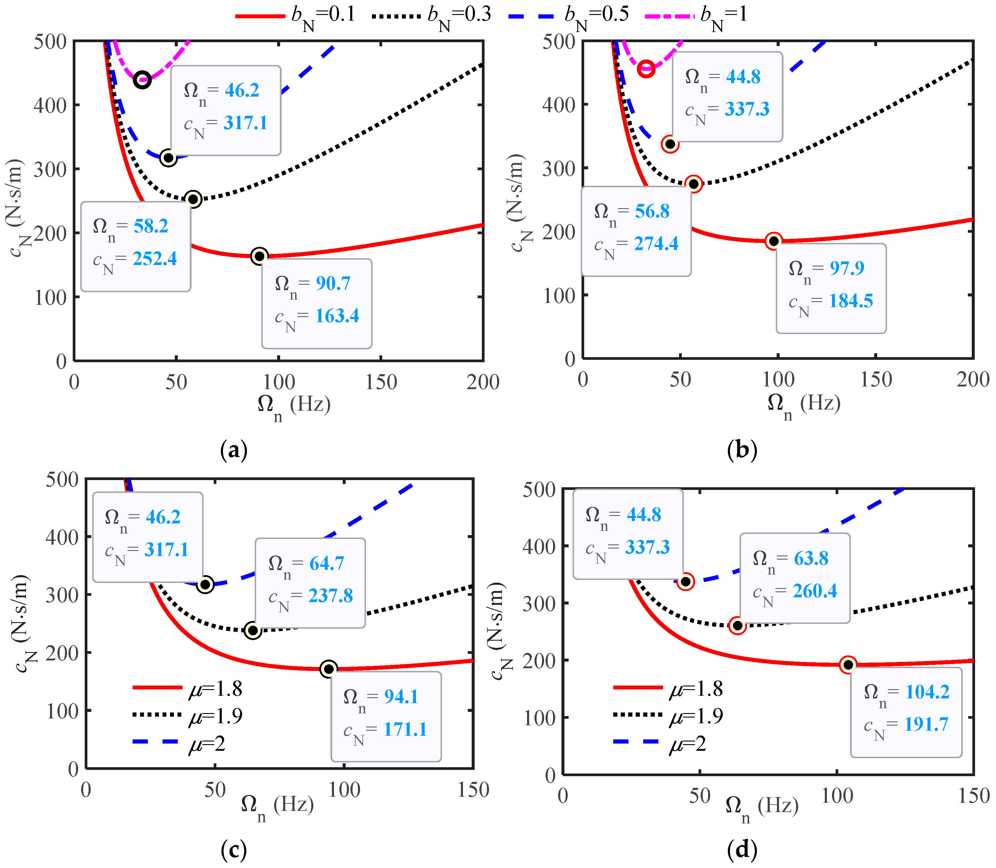
Equations (10)–(19) can be solved numerically. In order to have a more comprehensive view, the relationship curve between the damping coefficient cN (cN is converted from ζ NL units to N s/m) and the undamped natural frequency Ωn was plotted based on Equations (18) and (19) (Ωn is converted from ωn units to Hz), as shown in Figure 2. Figure 2a and Figure 2b show the variation curves of cN with Ωn corresponding to different bN (μ = 2) for the first and second orders, respectively, and Figure 2c and Figure 2d show the variation curves of cN with Ωn at different μ (bN = 0.5) for the first and second orders, respectively.
From Figure 2, there are minima in both figures (as circled in the figure), which have been verified to be exactly equal to the values calculated by Equation (19) and are the two critical damping values of the low-order vibration modes. The larger the bN and μ, the higher the inertia proportion of the fractional-order inerter, the higher the critical damping, and the lower the corresponding frequency.
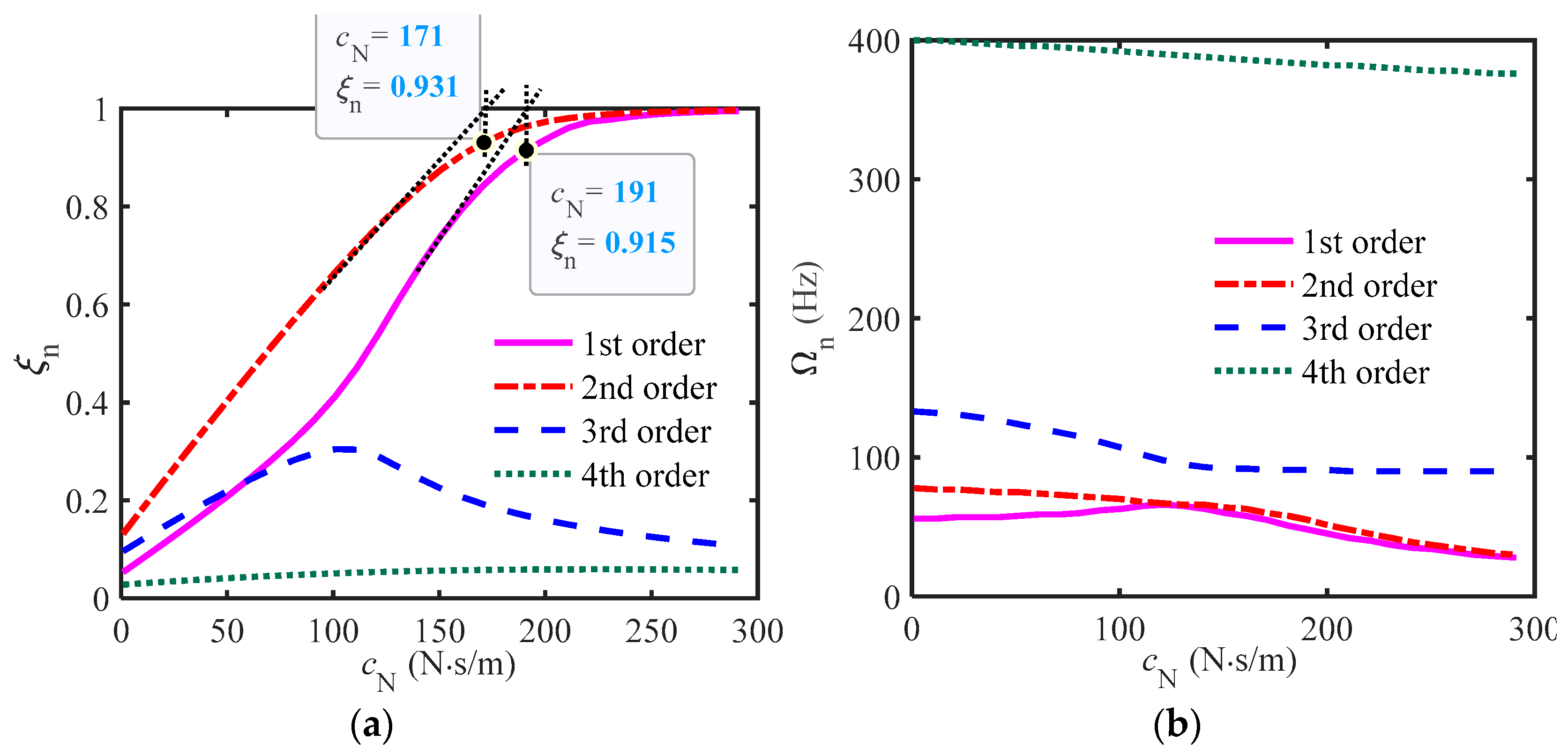
According to Equations (11), (14), and (16), the influence curves of the damping coefficient cN on the damping ratio ξn and frequency Ωn of the first four modes of the system were plotted, as shown in Figure 3 (μ = 2) and Figure 4 (μ = 1.8).
From Figure 3, when using an integer-order inerter (μ = 2), as the damping coefficient increases, the damping ratio of the first and second modes can reach one, which is the critical damping position. The critical damping coefficient marked in Figure 3a is equal to the minimum value marked in Figure 2a,b, further explaining that the two minimum values calculated according to Equations (18) and (19) are the critical damping corresponding to the first and second modes.
From Figure 4, the first- and second-order curves need to be extended to coincide with the theoretical calculation at the intersection point where the damping ratio is equal to one, indicating that there is a transitional state when using a fractional-order inerter. The main reason is that the fractional-order inerter comes with damping, while the actual critical damping is composed of cN and the equivalent damping of the inerter. Therefore, it is feasible to use cN at the intersection point of the extended line and one in the figure as the approximate critical damping.
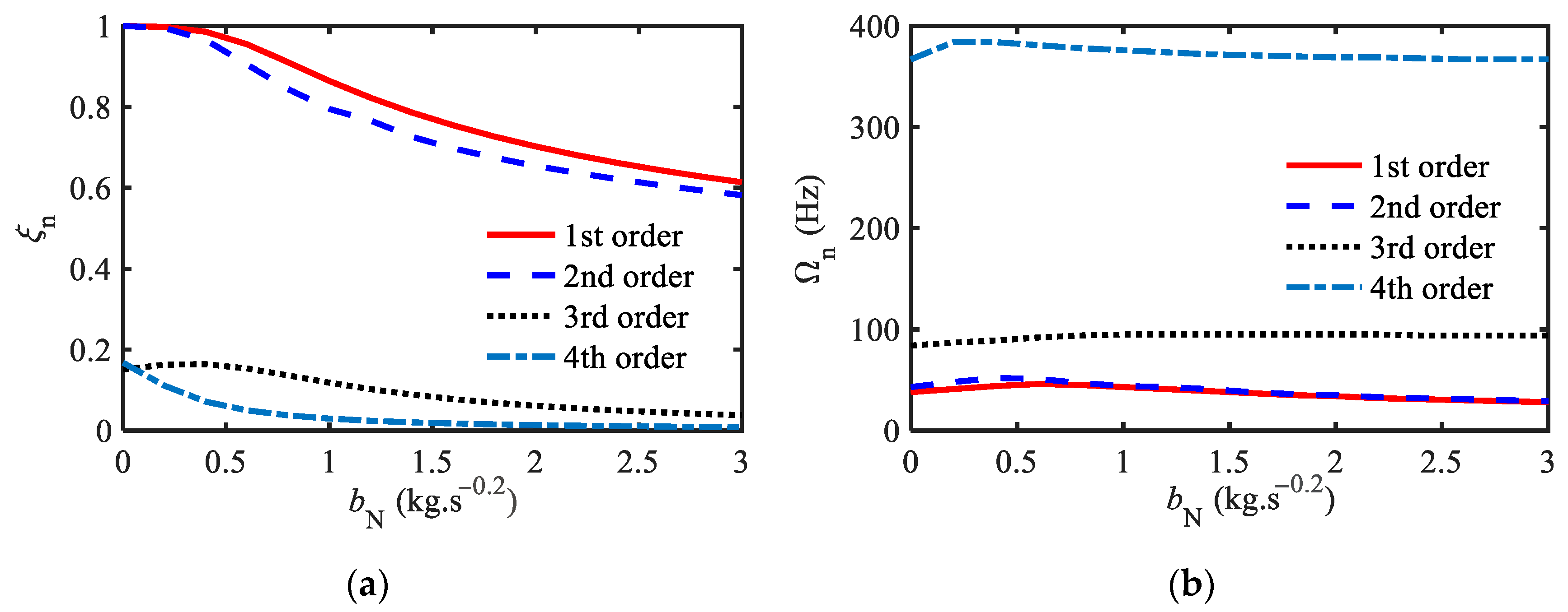
The curves of the inertance bN on the modal damping ratio and natural frequency are plotted below, as shown in Figure 5 (cN = 200, μ = 2) and Figure 6 (cN = 200, μ = 1.8).
From the two graphs, as bN increases, the damping ratio and natural frequency curve of high-order modes are basically the same for integer order and fractional order. However, when bN is small for the latter, ξn hardly decreases and then slowly decreases, indicating that the damping effect of first- and second-order modes in fractional order is more significant than that in integer order. In addition, due to cN = 200, μ = 1.8, the damping ratio has exceeded the critical damping value. As shown in Figure 6b, the first- and second-order frequencies almost overlap, with the first-order frequency disappearing.
To gain a clearer understanding of the impact of shock absorber parameters on frequency, the natural frequency Ωn and damped oscillation frequency Ωd for different combinations of shock absorber parameters are presented in Table 2.
From Table 2, when introducing integer-order inerters, Ωn = Ωd, the natural frequency is lower than that without vibration dampers; the use of fractional-order inerters and the introduction of dampers will result in Ωd < Ωn, while the high price change is not significant. When the damping coefficient and inertance are reasonably selected, there is a critical damping. For example, when the damping in the last two rows of the table is large, the first- and second-order damped oscillation frequencies are zero, indicating that they are no longer oscillating and have monotonic decay.

4. Vibration Suppression Effect

4.1. Vibration Mode Analysis

To compare the vibration suppression effect, first discuss the vibration modes under different boundary conditions, and then uniformly use one of the boundary conditions for calculation. Since the characteristic equation is a complex variable equation, H is also a complex vector. Let s = sR + isI, Hj = Hja + iHjb, then the vibration mode function (10) of the complex mode can be simplified into real and imaginary parts
Re ϕ x = C h H a T + S h H b T , Im ϕ x = C h H b T S h H a T
where
C h = cosh s I x cos s R x cosh s I x sin s R x cosh s R x cos s I x sinh s R x cos s I x , S h = sinh s I x sin s R x sinh s I x cos s R x sinh s R x sin s I x cosh s R x sin s I x , H a = H 1 a H 2 a H 3 a H 4 a ,   H b = H 1 b H 2 b H 3 b H 4 b
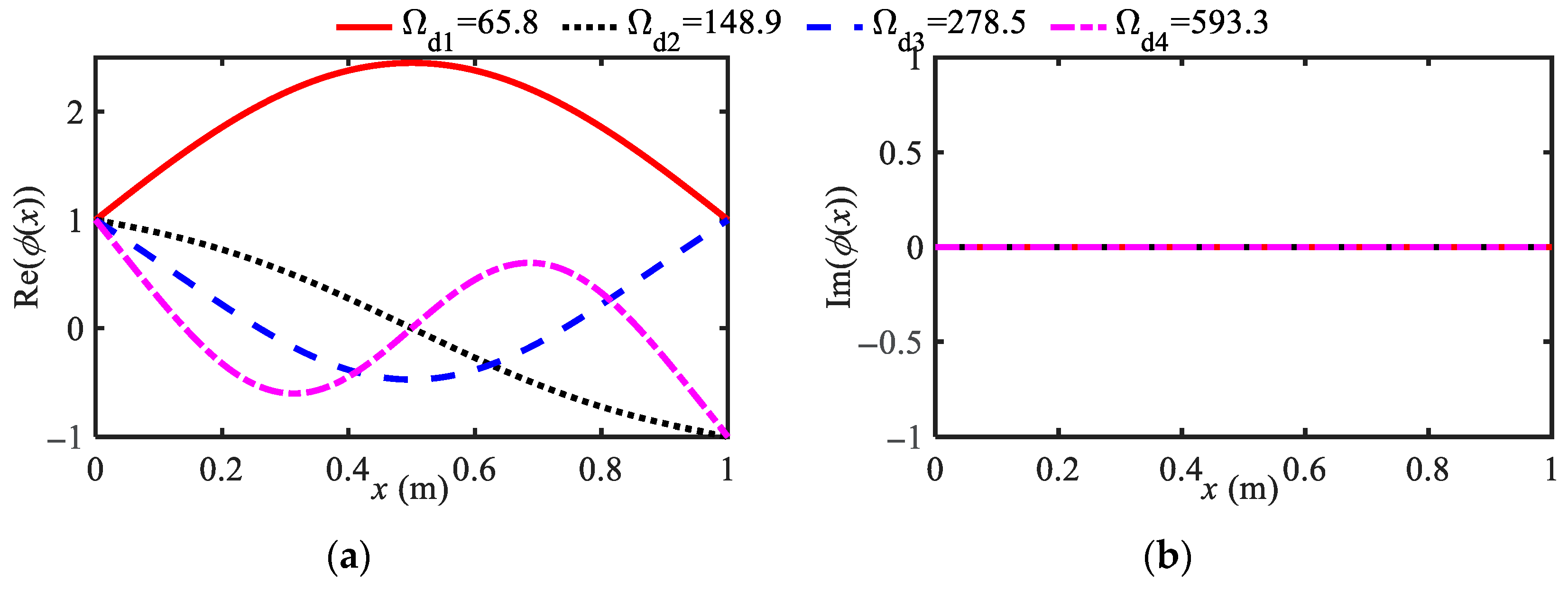
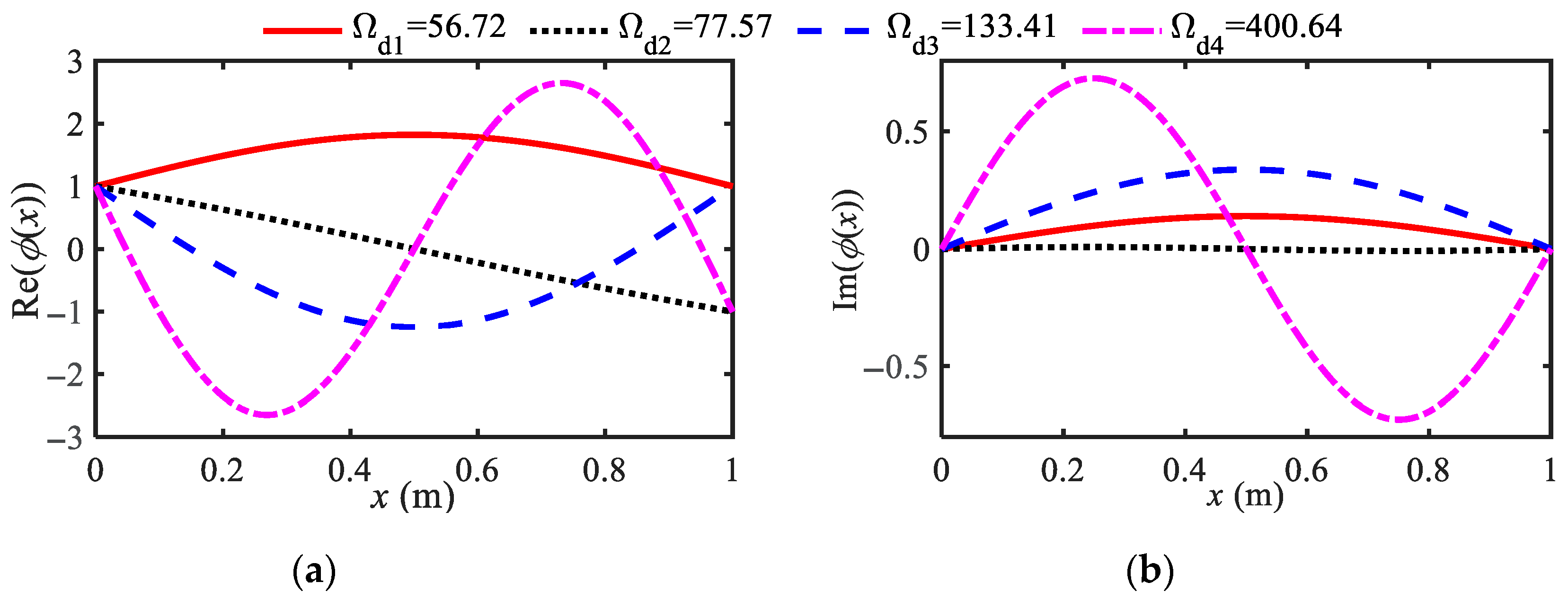
To conduct a comparative analysis under a unified standard, H1 is set to one. The vibration mode diagram without shock absorbers is depicted in Figure 7, showing the first- to fourth-order vibration modes as solid lines, dashed lines, dotted lines, and double-dotted lines, respectively. This vibration mode is initially used for comparative analysis and subsequently selected for response calculations, although the latter is not explicitly detailed.
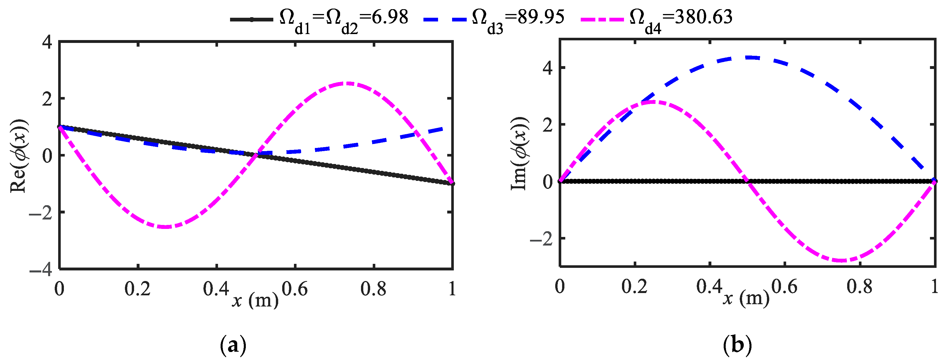
The real and imaginary vibration modes of the elastic beam using integer-order and fractional-order inerters are shown in Figure 8, respectively (parameters: μ = 1.8, cN = 0, bN = 0.5). From Figure 8, due to the damping characteristics of fractional-order inerters, there are imaginary vibration modes.
Figure 9 shows the vibration mode diagram for parameter combinations exceeding the critical damping (cN = 220 > 171). The figures show that when the critical damping is exceeded, the first- and second-order frequencies and modes almost overlap; that is, the first-mode frequency disappears, further indicating that the analysis of the critical damping of the first and second modes is accurate, and has little effect on the third and fourth modes.
From the above analysis of vibration modes, when considering the boundary conditions of the shock absorber, it is more suitable for theoretical analysis to obtain the characteristics of damping, frequency, and vibration modes, as well as the calculation formula for the critical damping of low-order modes. The boundary conditions only consider the spring support, and there are no imaginary vibration modes suitable for calculation and comparative analysis.

4.2. Galerkin Truncation Equation and Its Convergence

The Galerkin method is applied to truncate the dynamic Equation (2) of an elastic beam coupled with FOIB-VMD into an ordinary differential equation, assuming that the approximate solution for the lateral displacement of the beam is
w x , t = n = 1 N ϕ n x q n t
In the equation, N is the Galerkin truncation order, ϕn(x) is the modal function of the beam, and qn(t) is the generalized displacement of the beam’s lateral vibration. Equation (2) can be truncated by Galerkin to obtain an approximate system of ordinary differential equations for the system
0 1 1 N ϕ n x ϕ m x q ¨ t d x + ζ N n = 1 N ϕ n 0 ϕ m 0 q ˙ n t + n = 1 N ϕ n 1 ϕ m 1 q ˙ n t + μ N n = 1 N ϕ n 0 ϕ m 0 D μ q n t + n = 1 N ϕ n 1 ϕ m 1 D μ q n t + κ 2 0 1 1 N ϕ n 4 x q t ϕ m x d x + κ 2 λ 0 1 1 N ϕ n 4 x q ˙ t ϕ m x d x = g t 0 1 f x ϕ m x d x
According to the modal orthogonality property, when mn, it satisfies
0 1 ϕ n x ϕ m x d x = 0 , 0 1 ϕ n 4 x ϕ m x d x = 0
Therefore, Equation (22) can be abbreviated as
M m q ¨ m t + K m q m t + K m λ q ˙ m t + ζ N n = 1 N ϕ n 0 q ˙ n t ϕ m 0 + n = 1 N ϕ n 1 q ˙ n t ϕ m 1 + μ N n = 1 N ϕ n 0 D μ q n t ϕ m 0 + n = 1 N ϕ n 1 D μ q n t ϕ m 1 = F m g t
where
M m = 0 1 ϕ m x ϕ m x d x , K m = κ 2 s m 4 M m , C m = K m λ , F m = 0 1 f x ϕ m x d x , m = 1 , 2 , N ,
Under the action of generalized harmonic excitation, the fractional derivative term can be simplified using an approximate integer-order method to obtain the following relationship [20]
D μ q n t = Ω μ 1 cos ( μ 1 ) π 2 q ˙ n t + Ω μ 2 sin ( μ 1 ) π 2 q ¨ n t
Due to the external interference being a uniformly distributed harmonic excitation force f0cos(ωt), let f(x) = f0 be a constant, g(t) = cos(ωt), and ω = Ω/ω0. Unless otherwise specified later, the boundary conditions for comparative analysis are uniformly based on the Bo1 scheme, and the modal function ϕ(x) is calculated.
After introducing Equations (25) and (24), they can be organized into a set of classical second-order ordinary differential equations, which can be directly solved using numerical methods such as Runge–Kutta. The initial values of the system are set as follows
q 1 = 0.02 ,   q ˙ 1 = 0 ,   q j = 0 ,   q ˙ j = 0 ,   j = 2 N
Special note: the coordinate values used in the simulation below are the dimensional values of the original system, that is, the time is T = t/ω0, and the excitation frequency Ω is obtained by converting the unit rad/s to Hz. For convenience, Ω is also used. The vertical axis represents the dimensionless lateral displacement w(x, t), which is reduced to W(X, T). The amplitude of the amplitude frequency characteristic is represented by |W(X, Ω)|. Figure 10a and Figure 10b respectively show the free vibration responses and the steady-state amplitude frequency characteristics of the left end of the beam at different Galerkin truncation orders (μ = 1.8, cN = 1, bN = 0.1).
From the above two figures, both the time-domain response and amplitude frequency characteristics show that the fourth (N = 4) and sixth (N = 6) orders have higher accuracy and almost overlap. Therefore, considering both computational performance and computation time, the fourth-order truncation is adopted.

4.3. Analysis of Vibration Suppression Effect

(1)
Vibration suppression performance indicators
The following discusses the influence of shock absorber parameters on amplitude frequency characteristics and verifies whether the peak frequency of the actual response is consistent with the theoretically calculated damped oscillation frequency. Using the method described in the previous section, calculate the first four undamped natural frequencies Ωn and the first four damped oscillation frequencies Ωd (partial parameter combination), as shown in Table 3.
Below are two quantitative evaluation indicators for vibration suppression performance, which mainly compare the amplitude and frequency reduction in the main resonance position, namely, the main resonance amplitude reduction ratio RA and the main resonance frequency reduction ratio RΩ. The specific relationship equation is as follows
R A = A 0 A j A 0 × 100 %   and   R Ω = Ω 0 Ω j Ω 0 × 100 %
In the formula, A0 and Ω0 respectively represent the main resonance amplitude (left end 0.04129, middle 0.1012) and main resonance frequency 65.8 Hz without shock absorbers, while Aj and Ωj respectively represent the main resonance amplitude and main resonance frequency with different shock absorbers.
(2)
The influence of FOIB-VMD parameters on vibration suppression performance
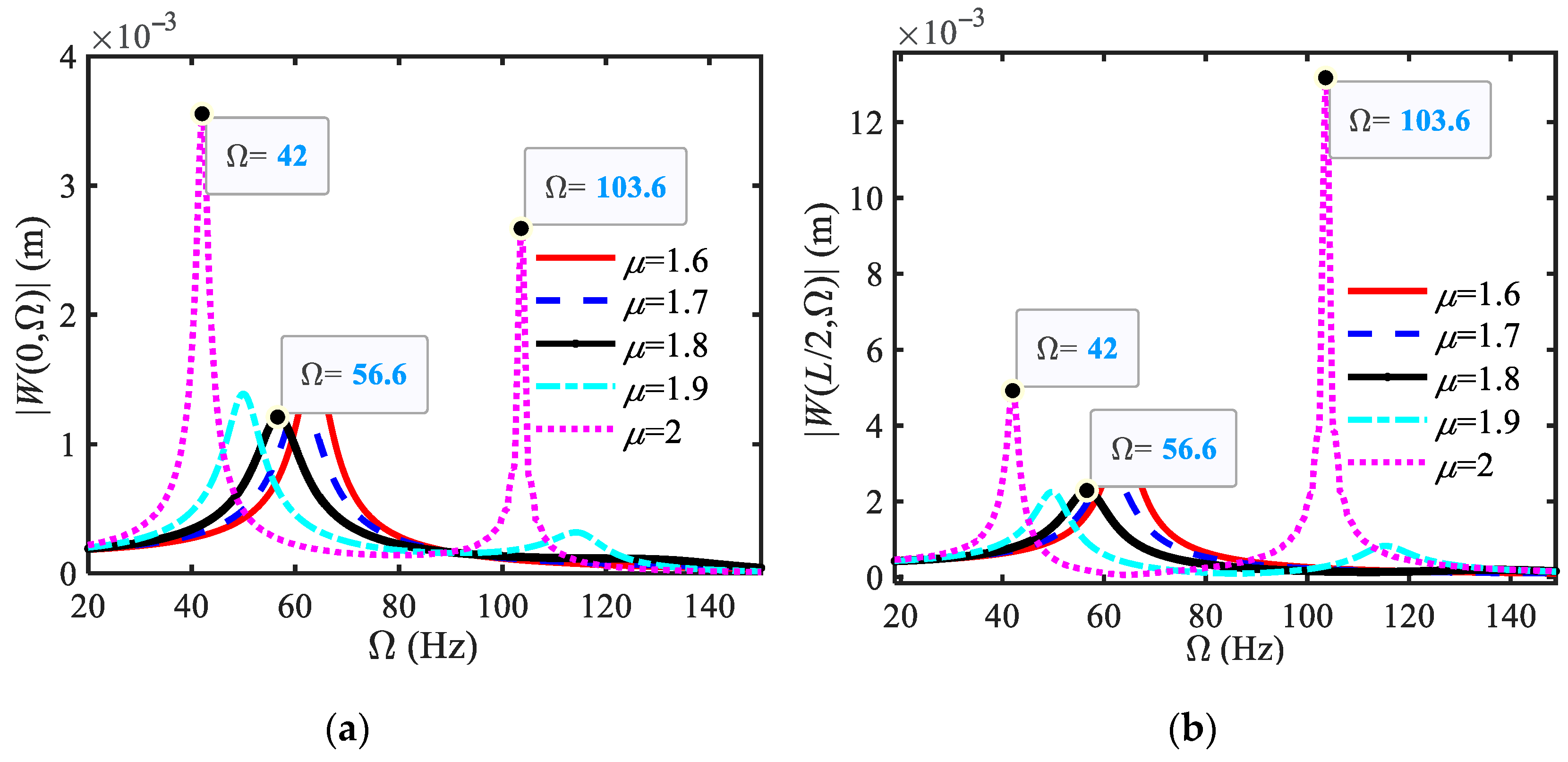
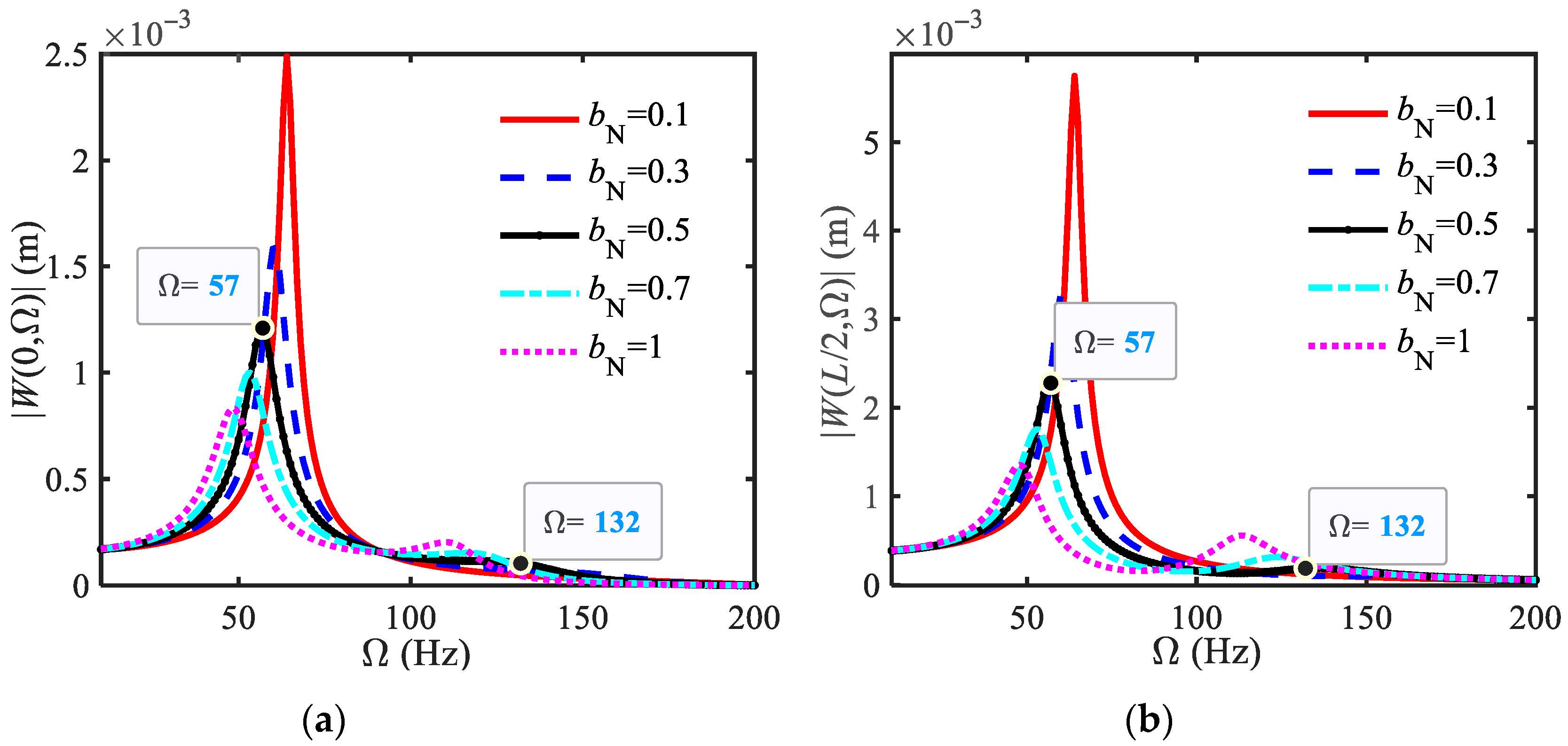
From the previous analysis, under the action of uniformly distributed harmonic excitation force, the modal shapes of the first and third principal resonances of the elastic beam are symmetrically distributed about the midpoint of the beam. Therefore, only the amplitude frequency curves of the left and the midpoint of the beam are given below. Figure 11, Figure 12 and Figure 13 show the effects of three parameters (μ, bN, and cN) of the shock absorber on the amplitude frequency characteristics of the left and middle positions of the beam.
From Figure 11, as μ increases, the resonance peak first decreases and then increases. The effect of the first-order main resonance frequency becoming smaller is more obvious, and there is a clear third-order resonance peak near two, indicating poor overall performance.
From Figure 12, the effect of changes in bN on the left and middle positions of the beam is not as significant as that of cN, but its impact on the resonance peak and frequency is basically the same; that is, for the decrease in the main resonance amplitude and frequency, the larger the bN, the better.
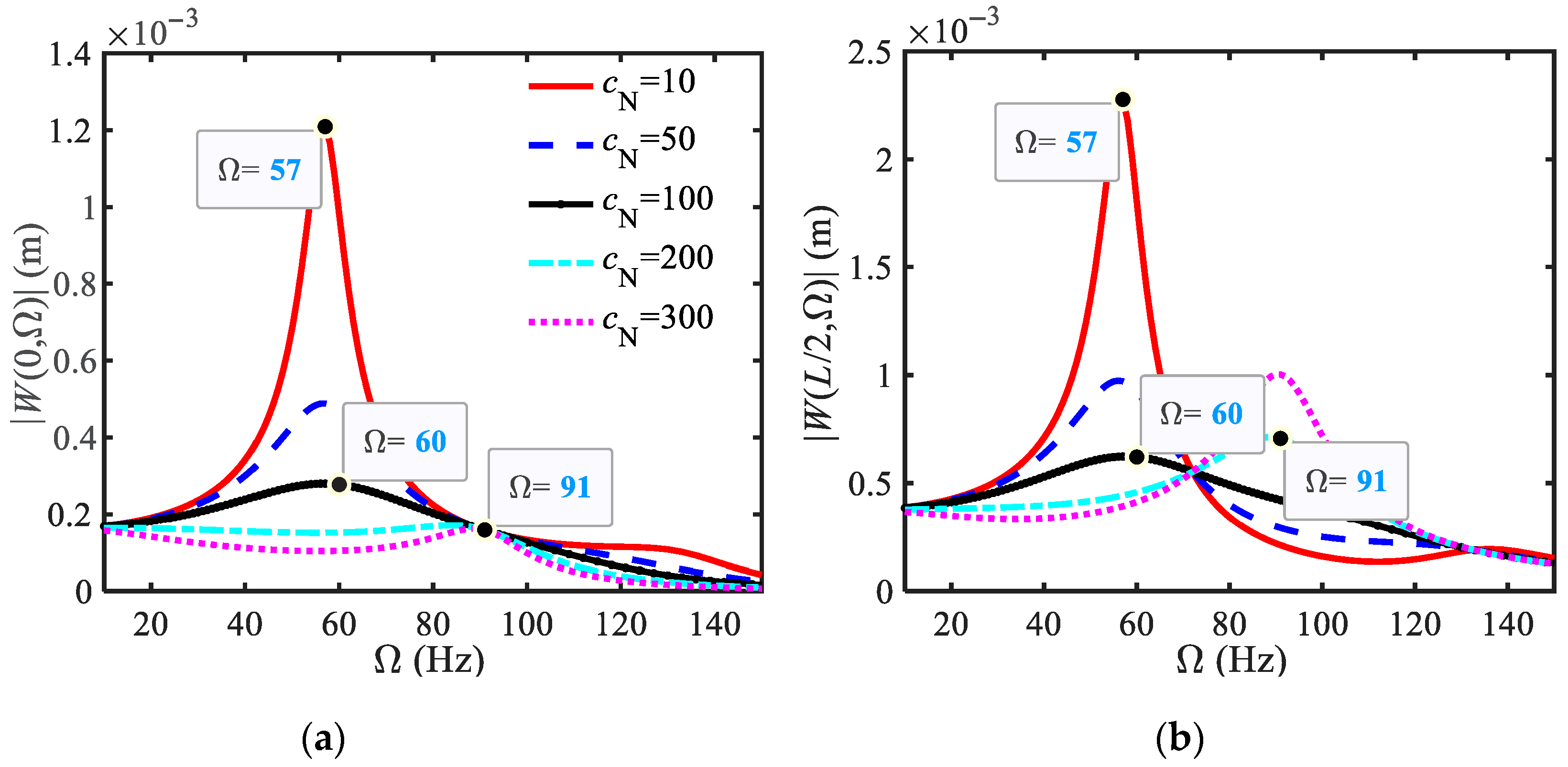
From Figure 13, cN has a very significant impact on amplitude. The larger the damping before reaching the critical damping, the better the damping effect. When it is near the critical damping (cN = 200), the comprehensive damping effect is better. The first and third resonance peaks are almost at the same height, and the damping effect is limited when it exceeds the critical damping more (cN = 300).
The main resonance frequency (Ω) measured in each figure is basically consistent with Ωd in Table 3, so the reduction ratio of the main resonance frequency RΩ (%) can be directly calculated from the data in Table 3, as shown in Table 4.
Firstly, introducing inerters can reduce the main resonance frequency. When underdamped damping is selected, using integer-order inerters results in a larger RΩ, indicating better mass effect. When the damping exceeds the critical damping, RΩ is particularly large (as shown in the table with RΩ = 83.89%), but from Figure 13, its maximum peak is the third resonance peak, because the first-order resonance peak disappears at this time. This also indicates that using critical damping and over-critical damping may not necessarily reduce the maximum resonance peak. That is, when the damping approaches or exceeds the critical damping, RΩ cannot reflect the real situation and cannot be blindly increased. Another indicator, RA, should also be combined with the design parameters. Table 5 below shows RA under different bN and μ.
From Table 5, when introducing fractional-order inerters, only small damping is required, and RA is greater than 94%, indicating a significant vibration reduction effect. The influence of μ on RA has a maximum value, and the best effect is probably at μ = 1.8, and the worst effect is at μ = 2; the influence of bN is basically monotonically increasing, and the larger it is, the better the vibration suppression effect.
Table 6 shows the average values of RA at the left and middle positions of the beam when the damping coefficient is different times of the critical damping.
Table 6 shows that when an integer-order inerter is used and the damping exceeds 0.6 times the critical damping, the improvement in vibration reduction performance is weak. When measured by RA exceeding 95% and higher cost-effectiveness, the damping can be selected as 0.2~0.6 times the critical damping. However, when using fractional-order inerters and measuring them with similar standards, the damping can be selected as 0.05~0.6 times the critical damping to achieve good vibration reduction performance. In addition, FOIB-VMD has better vibration reduction performance compared to integer-order VMD, and requires significantly smaller damping values, which is of great significance for the design of shock absorbers.

5. Conclusions

This article analyzes the dynamic behavior of elastic beams with fractional-order inerter-based dampers at both ends. We derive critical damping conditions, evaluate damping effects, and establish parameter selection rules to guide engineering applications. The main conclusions are as follows:
(1)
By using the complex modal analysis method, a design method for the critical damping of an elastic beam with fractional-order inertial damping structures in the first-and second-order models was proposed for the first time, and the accuracy of the critical damping calculation formula was verified through specific examples.
(2)
Meanwhile, research has shown that the derivative order μ and inertance bN of fractional-order inerters have an beneficial impact on critical damping and primary resonance frequency. The higher μ and bN, the lower the main resonance frequency and the greater the critical damping. Conversely, the opposite is true, indicating that bN reflects the inertia characteristics, while μ reflects the proportion of attached damping.
(3)
Using the main resonance amplitude and frequency attenuation rate (RA and RΩ) as indicators, the impact of shock absorber parameters on vibration suppression was analyzed. (1) When using a fractional-order inerter, the vibration reduction effect is better than that of an integer-order inerter. However, expanding the vibration reduction bandwidth is slightly inferior, and the vibration reduction effect is best when μ is around 1.8. (2) The larger bN, the better. (3) Damping has a significant vibration reduction effect on beams when selecting under damping, and the critical damping proposed in this article helps us clarify the range of under damping. With first-order critical damping, the first-order main resonance frequency of the system disappears, while higher-order frequencies decrease, and the RA exceeds 99%. This demonstrates that the function of critical damping in traditional single-degree-of-freedom systems remains consistent. Based on the optimal average RA range (95–98%) and higher cost-effectiveness, selecting a damping value of 0.05~0.6 times the critical damping ensures better overall vibration suppression performance.
In summary, the introduction of a fractional-order inerter can not only reduce the overall mass of VMD through the equivalent mass substitution effect, but also synchronously reduce the demand threshold for traditional damping components in the system through its additional damping characteristics. At the same time, it simplifies the optimization process for actual damper design and has certain theoretical guidance value for improving the vibration reduction effect of aerospace precision equipment, transportation vehicles, bridges, and other scenarios.

Author Contributions

Writing—original draft preparation, Y.C.; supervision, N.C. All authors have read and agreed to the published version of the manuscript.

Funding

This research received no external funding.

Institutional Review Board Statement

Not applicable.

Informed Consent Statement

Not applicable.

Data Availability Statement

The original contributions presented in the study are included in the article. Further inquiries can be directed to the corresponding authors.

Conflicts of Interest

The authors declare that there are no conflicts of interest regarding the publication of this paper.

References

  1. Zhang, A.L.; Li, C.H.; Liu, X.C.; Chen, X. Static performance of welded hollow spherical bolted joint with H-beams. Structures 2025, 76, 109039. [Google Scholar] [CrossRef]
  2. Hao, M.; Zhou, S.; Han, Y.; Zhu, Z.; Yang, Q.; Sun, P.; Fan, J. Performance Evaluation of Damaged T-Beam Bridges with External Prestressing Reinforcement Based on Natural Frequencies. Struct. Durab. Health Monit. 2025, 19, 399–415. [Google Scholar] [CrossRef]
  3. Rodrigues, R.; Alazard, D.; Sanfedino, F.; Mauriello, T.; Iannelli, P. Modeling and analysis of a flexible spinning Euler-Bernoulli beam with centrifugal stiffening and softening: A linear fractional representation approach with application to spinning spacecraft. Appl. Math. Model. 2025, 137 Pt B, 115699. [Google Scholar] [CrossRef]
  4. Zhao, Y.; Du, J.; Chen, Y.; Liu, Y. Dynamic Behavior and Vibration Suppression of a Generally Restrained Pre-pressure Beam Structure Attached with Multiple Nonlinear Energy Sinks. Acta Mech. Solida Sin. 2023, 36, 116–131. [Google Scholar] [CrossRef]
  5. Wang, B.; Derbeli, M.; Barambones, O.; Yousefpour, A.; Jahanshahi, H.; Bekiros, S.; Aly, A.A.; Alharthi, M.M. Experimental validation of disturbance observer-based adaptive terminal sliding mode control subject to control input limitations for SISO and MIMO systems—ScienceDirect. Eur. J. Control. 2022, 63, 151–163. [Google Scholar] [CrossRef]
  6. Zhang, W.Y.; Niu, M.Q.; Deng, L.F.; Fan, Y.; Chen, L.Q. Dynamic Analysis and Optimization on Passive/Active Vibration Reduction of a Beam Structure with Distributed Smart Foams. Int. J. Struct. Stab. Dyn. 2025, 25, 2550063. [Google Scholar] [CrossRef]
  7. Zhang, X.Y.; Chen, J.; Zhang, W. Optimal placement of piezoelectric actuator/sensor pairs for active vibration control of beams with different boundary conditions. Mech. Based Des. Struct. Mach. 2025, 53, 2262–2279. [Google Scholar] [CrossRef]
  8. Chowdhury, S.; Adhikari, S. Structural vibration control using nonlinear damping amplifier friction vibration absorbers. Appl. Math. Mech. 2025, 46, 965–988. [Google Scholar] [CrossRef]
  9. Soltani, M.; Fesharaki, J.J.; Galehdari, S.A.; Esfahani, R.T.; Shahgholi, M.A. comprehensive evaluation of the vibration control approach of the multi-layer sandwich composite piezoelectric micro-beam using higher-order elasticity theory and surface energy. Structures 2024, 60, 105880. [Google Scholar] [CrossRef]
  10. Duc, D.M.; Hung, T.Q.; Tu, T.M. Analytical and mesh-free approaches to dynamic analysis and active control of smart FGP-GPLRC beam. Structures 2023, 56 (Suppl. C), 105020. [Google Scholar] [CrossRef]
  11. Fu, Y.; Li, H.B.; Reng, J.N. Research Progress of Damping and Vibration Reduction Technology Used in Aerospace. Mater. Res. Appl. 2022, 16, 656–662. [Google Scholar] [CrossRef]
  12. Kumar, K.R.; Narayanan, S. Active vibration control of beams with optimal placement of piezoelectric sensor/actuator pairs. Smart Mater. Struct. 2008, 17, 055008. [Google Scholar] [CrossRef]
  13. Khot, S.M.; Yelve, N.P.; Kumar, P.; Purohit, G.A.; Singh, D. Experimental investigation of performances of different optimal controllers in active vibration control of a cantilever beam. ISSS J. Micro Smart Syst. 2019, 8, 101–111. [Google Scholar] [CrossRef]
  14. Marian, L.; Giaralis, A. Optimal design of a novel tuned mass-damper–inerter (TMDI) passive vibration control configuration for stochastically support-excited structural systems. Probabilistic Eng. Mech. 2014, 38, 156–164. [Google Scholar] [CrossRef]
  15. Shi, X.; Shi, W.; Lin, K.; Xing, L.; Zhu, S. Optimal design of tuned inerter dampers with series or parallel stiffness connection for cable vibration control. Struct. Control. Health Monit. 2020, 28, e2673.1–e2673.26. [Google Scholar] [CrossRef]
  16. Shen, Y.; Hua, J.; Fan, W.; Liu, Y.; Yang, X.; Chen, L. Optimal design and dynamic performance analysis of a fractional-order electrical network-based vehicle mechatronic ISD suspension. Mech. Syst. Signal Process. 2023, 184, 109718. [Google Scholar] [CrossRef]
  17. Zhang, X.; Li, H.; Cheng, J.; Sheng, L.; Yao, Y. Adaptive stability mechanism of high-speed train employing parallel inerter yaw damper. Veh. Syst. Dyn. 2023, 61, 38–57. [Google Scholar] [CrossRef]
  18. Shen, Y.; Chen, L.; Yang, X.; Shi, D.; Yang, J. Improved design of dynamic vibration absorber by using the inerter and its application in vehicle suspension. J. Sound Vib. 2016, 361, 148–158. [Google Scholar] [CrossRef]
  19. Swift, S.J.; Smith, M.C.; Glover, A.R.; Papageorgiou, C.; Gartner, B.; Houghton, N.E. Design and modelling of a fluid inerter. Int. J. Control 2013, 86, 2035–2051. [Google Scholar] [CrossRef]
  20. Chen, Y.; Xu, J.; Tai, Y.; Xu, X.; Chen, N. Critical damping design method of vibration isolation system with both fractional-order inerter and damper. Mech. Adv. Mater. Struct. 2022, 29, 1348–1359. [Google Scholar] [CrossRef]
  21. Chen, Y.; Tai, Y.; Xu, J.; Xu, X.; Chen, N. Vibration Analysis of a 1-DOF System Coupled with a Nonlinear Energy Sink with a Fractional Order Inerter. Sensors 2022, 22, 6408. [Google Scholar] [CrossRef]
  22. Chen, Y.D.; Chen, N. A New Fractional-Order Constitutive Model and Rough Design Method for Fluid-Type Inerters. Materials 2025, 18, 2556. [Google Scholar] [CrossRef]
  23. Ding, H.; Zhu, M.H.; Chen, L.Q. Nonlinear vibration isolation of a viscoelastic beam. Nonlinear Dyn. 2018, 92, 325–349. [Google Scholar] [CrossRef]
  24. Ding, H.; Lu, Z.Q.; Chen, L.Q. Nonlinear isolation of transverse vibration of pre-pressure beams. J. Sound Vib. 2019, 442, 738–751. [Google Scholar] [CrossRef]
  25. Zhang, Z.; Zhang, Z. Inclined Boundary Inertial Vibration Absorber for Elastic Beam. Open J. Acoust. Vib. 2025, 13, 22–36. [Google Scholar] [CrossRef]
  26. Sinha, A. Vibration of Mechanical Systems; Cambridge University Press: Cambridge, UK, 2010. [Google Scholar]
  27. Wang, P.; Wang, Q.; Xu, X.; Chen, N. Fractional Critical Damping Theory and Its Application in Active Suspension Control. Shock. Vib. 2017, 2017 Pt 7, 2738976.1–2738976.8. [Google Scholar] [CrossRef]
  28. Zhou, Z.; Fan, S.; Cai, Y.; Luo, F. Effect of Noise Reduction on Thin-Walled Parts of Engine Using Damping Material Treatment. Trans. CSICE 2022, 40, 89–95. [Google Scholar] [CrossRef]
  29. Ogata, K. Modern Control Engineering, 5th ed.; Prentice-Hall: Hoboken, NJ, USA, 2025. [Google Scholar]
  30. Bulatovic, R.M. On the critical damping in multi-degree-of-freedom systems. Mech. Res. Commun. 2002, 29, 315–319. [Google Scholar] [CrossRef]
  31. Main, J.A.; Jones, N.P. Free Vibrations of Taut Cable with Attached Damper. I: Linear Viscous Damper. J. Eng. Mech. 2002, 128, 1062–1071. [Google Scholar] [CrossRef]
  32. Xu, J.; Chen, Y.; Tai, Y.; Xu, X.; Shi, G.; Chen, N. Vibration analysis of complex fractional viscoelastic beam structures by the wave method. Int. J. Mech. Sci. 2020, 167, 12. [Google Scholar] [CrossRef]
  33. Chen, W. Fractional Derivative Modeling of Mechanics and Engineering Problems; Science Press: Beijing, China, 2010. [Google Scholar]
  34. Xu, Y.; Xu, Z.D.; Hu, H.; Guo, Y.Q.; Huang, X.H.; Zhang, Z.W.; Zhang, T.; Xu, C. Experiment, Simulation, and Theoretical Investigation of a New Type of Interlayer Connections Enhanced Viscoelastic Damper. Int. J. Struct. Stab. Dyn. 2025, 25, 2550045. [Google Scholar] [CrossRef]
  35. Aghababaiyan, M.R.; Dehkordi, M.B.; Fallah, A. A new approach for nonlinear transient dynamic analysis of micro SMA beam considering size effect and instantaneous phase transformation. Proc. Inst. Mech. Eng. Part C J. Mech. Eng. Sci. 2024, 238, 2205–2214. [Google Scholar] [CrossRef]
Figure 1. An elastic beam model with shock absorbers (FOIB-VMD) at the boundary.
Buildings 15 02911 g001
Figure 2. (a,b) are the curves of cN with Ωn at different bN; (c,d) are the curves of cN with Ωn at different μ: (a) 1st order. (b) 2nd order. (c) 1st order. (d) 2nd order.
Buildings 15 02911 g002
Figure 3. The curves of ξn (a) and Ωn (b) of the first four orders changing with cN.
Buildings 15 02911 g003
Figure 4. The curves of ξn (a) and Ωn (b) of the first four orders changing with cN (μ = 1.8).
Buildings 15 02911 g004
Figure 5. The curves of ξn (a) and Ωn (b) of the first four orders changing with bN.
Buildings 15 02911 g005
Figure 6. The curves of ξn (a) and Ωn (b) of the first four orders changing with bN.
Buildings 15 02911 g006
Figure 7. (a) Real part and (b) imaginary part vibration mode of the beam without a vibration damper.
Buildings 15 02911 g007
Figure 8. (a) Real part and (b) imaginary part vibration mode of the beam (μ = 1.8, cN = 0, bN = 0.5).
Buildings 15 02911 g008
Figure 9. (a) Real part and (b) imaginary part vibration mode of the beam (μ = 1.8, cN = 220, bN = 0.5).
Buildings 15 02911 g009
Figure 10. (a) Free vibration response and (b) amplitude frequency characteristics of the left end of the beam under different Galerkin truncation orders.
Buildings 15 02911 g010
Figure 11. Amplitude frequency characteristics of the beam at different μ (bN = 0.5, cN = 10): (a) Left end of the beam. (b) Middle position of the beam.
Buildings 15 02911 g011
Figure 12. Amplitude frequency characteristics of the beam at different bN (cN = 10, μ = 1.8): (a) Left end of the beam. (b) Middle position of the beam.
Buildings 15 02911 g012
Figure 13. Amplitude frequency characteristics of the beam at different cN. (bN = 0.5, μ = 1.8): (a) Left end of the beam. (b) Middle position of the beam.
Buildings 15 02911 g013
Table 1. Physical and geometric parameters of aluminum alloy beam and FOIB-VMD.
NameSymbolValue (Unit)
Young’s modulusE68.9 GPa
Density ρ2800 kg/m3
Viscous damping Λ0 N s/m2
Vertical stiffness KL = KR46,025.2 N/m
Length L0.5 m
Sectional area A2 × 10−4 m2
Sectional moment of inertia I1.67 × 10−9 m4
Damper damping coefficient cNN s/m
Inertance bNkg (μ = 2)
kg sμ−2 (1 < μ < 2)
Derivative order of the inerter μ/
Table 2. Ωn and Ωd (Hz) for different combinations of shock absorber parameters.
FOIB-VMD ParametersΩn (Hz)Ωd (Hz)
1st2nd3rd4th1st2nd3rd4th
cN = 0, bN = 065.8148.9278.5593.365.8148.9278.5593.3
μ = 2, cN = 0bN = 0.159.688.6144.9403.459.688.6144.9403.4
bN = 0.253.868.6120.1383.753.868.6120.1383.7
bN = 0.348.957.9110.0376.448.957.9110.0376.4
μ = 1.8, cN = 0bN = 0.164.0123.9212.7487.164.0123.7212.2486.8
bN = 0.262.2106.8178.2444.362.2106.4177.5443.9
bN = 0.360.494.5157.4422.460.494.0156.7422.1
bN = 0cN = 5067.6159.1280.6566.667.2140.2246.3552.5
cN = 10073.5102.8157.3423.50.00.0154.6393.7
cN = 15054.667.980.9375.90.00.079.5365.7
cN = 20038.843.784.9367.80.00.083.9362.6
Table 3. Ωn and Ωd of the first four orders under different FOIB-VMD parameters.
FOIB-VMD ParametersΩn (Hz)Ωd (Hz)
1st2nd3rd4th1st2nd3rd4th
cN = 0, bN = 065.8148.9278.5593.365.8148.9278.5593.3
bN = 0.5, μ = 1.8cN = 1056.977.7132.7400.156.776.4131.8400.0
cN = 10063.470.3107.5392.357.952.7102.4391.8
cN = 20045.952.191.2383.010.618.290.0382.3
bN = 0.5, μ = 2cN = 1041.746.2101.7370.141.746.1101.7370.1
cN = 10042.146.2100.7370.140.543.8100.6370.1
cN = 20043.246.298.2369.935.735.998.0369.9
Table 4. Percentage reduction in main resonance frequency RΩ (%).
FOIB-VMD ParametersRΩ (%)
bN = 0.5, μ = 1.8cN = 1013.83
cN = 10012.01
cN = 20083.89
bN = 0.5, μ = 2cN = 1036.63
cN = 10038.45
cN = 20045.74
Table 5. The RA (%) under different bN and μ.
FOIB-VMD
Parameters
RA (%)
(Left End of the Beam)
RA (%)
(Middle Position of the Beam)
Average Values of RA(%) on the Left and Middle Position of the Beam
bN = 0.5, cN = 10μ = 1.796.7293.0594.89
μ = 1.897.0794.4895.78
μ = 1.996.6394.5595.59
μ = 291.3968.2079.80
μ = 1.8, cN = 10bN = 0.193.9786.0790.02
bN = 0.396.1592.0394.09
bN = 0.597.0794.4895.78
bN = 0.797.5895.7496.66
Table 6. Average values of RA (%) on the left and middle positions of the beam.
FOIB-VMD Parameters Times of Critical Damping
μ = 2, bN = 0.5, cN = Times × 31700.050.10.20.30.40.50.60.70.80.911.1
Average values of RA (%) on the left and middle positions of the beam
65.4091.2794.5496.5797.3897.8498.1298.2598.2798.2998.2798.2198.15
μ = 1.8, bN = 0.5, cN = Times × 17100.050.10.20.30.40.50.60.70.80.911.1
Average values of RA (%) on the left and middle positions of the beam
93.3195.7896.6397.7298.2698.5898.7898.9399.0299.0799.0599.0298.97
Disclaimer/Publisher’s Note: The statements, opinions and data contained in all publications are solely those of the individual author(s) and contributor(s) and not of MDPI and/or the editor(s). MDPI and/or the editor(s) disclaim responsibility for any injury to people or property resulting from any ideas, methods, instructions or products referred to in the content.