Article

Investigating the Double-Fissure Interactions of Hydraulic Concrete Under Three-Point Bending: A Simulation Study Using an Improved Meshless Method

1
Yanhuanding Water Pumping Administration of Ningxia Autonomous Region, Wuzhong 751199, China
2
Materials & Structural Engineering Department, Nanjing Hydraulic Research Institute, Nanjing 210098, China
3
Water Conservancy Project Construction Center of Ningxia Autonomous Region, Yinchuan 756501, China
4
School of Transportation and Civil Engineering, Nantong University, Nantong 226019, China
*
Authors to whom correspondence should be addressed.
Buildings 2025, 15(16), 2898; https://doi.org/10.3390/buildings15162898
Submission received: 18 July 2025 / Revised: 5 August 2025 / Accepted: 13 August 2025 / Published: 15 August 2025
(This article belongs to the Section Building Structures)

Abstract

Hydraulic concrete is prone to cracking and interactive propagation under complex stress, threatening its structural integrity and service life. To address limitations of traditional numerical methods (e.g., mesh dependency in FEM) and imprecision of existing meshless methods for characterizing multi-fissure interactions, this study improved SPH to model double-crack interactions in hydraulic concrete under three-point bending and clarify the underlying mechanisms. A modified SPH framework was developed by introducing a failure parameter (ξ) to refine the kernel function, enabling simulation of particle progressive failure via the Mohr–Coulomb criterion; a three-point bending numerical model of concrete beams containing double precast fissures (induced and obstacle) was established, with simulations under varying obstacle fissure angles (α = 0–75°) and distances (d = 0.02–0.06 m). The results show that the obstacle fissure angles significantly regulate the crack paths: as the α increases, the tensile stress concentration shifts from the obstacle fissure’s middle to its ends, causing cracks to deflect toward the lower end, with a reduced propagation length and lapping time; at an α = 75°, the obstacle fissure’s lower tip dominates failure, forming an “induced fissure–lower end of obstacle fissure–top” penetration mode. The fissure distances affect the stress superposition: a smaller d (e.g., 0.02 m) induces vertical propagation and rapid lapping with the obstacle fissure’s lower end, while a larger d (e.g., 0.06 m) weakens the stress at the induced fissure tip, promoting horizontal deflection toward the obstacle fissure’s upper end and transforming the failure into “upper-end dominated.” This confirms that the improved SPH method effectively simulates crack behaviors, providing insights into multi-fissure failure mechanisms and theoretical support for hydraulic structure crack control and safety evaluation.

1. Introduction

Concrete is widely used in hydraulic engineering due to its advantages of strong plasticity, diverse strength grades, and economic durability. However, its low tensile strength makes hydraulic concrete structures prone to crack initiation when influenced by factors such as temperature changes, foundation settlement, steel corrosion, and overloading [1,2]. For example, parallel cracks in a bank slope were observed in Switzerland [3], parallel cracks appeared in the Xiaowan Arch Dam during the initial pouring stage [4], and various cracks (vertical, nearly vertical, and horizontal cracks on the upstream face) were generated during the construction and operation of one arch dam [5]. Longitudinal and transverse joints, as well as horizontal construction joints, are set in mass concrete to meet construction temperature control requirements. If the grouting is poor, the joint surfaces may open under the influence of temperature and other factors, forming vertical-approaching angle cracks. The presence of cracks weakens a structure’s strength. Under complex dynamic and static loads (e.g., water pressure and earthquakes), the initial cracks can further propagate through their interaction, causing issues such as concrete carbonization, leakage, and corrosion, which shorten the structure’s service life or can even lead to failure. A 1988 survey by the International Commission on Large Dams showed that the interactive extension of cracks is a key factor in concrete dam failure. Therefore, studying the interactive propagation behavior of concrete cracks and exploring the crack propagation and evolution mechanism are of great significance.
In recent years, numerous theoretical, experimental, and numerical simulation studies on concrete have been conducted by scholars. Theoretical studies have endeavored to summarize and extract the interaction mechanism between fissures and the crack propagation law in concrete. For instance, Guo et al. proposed an electrochemical–mechanical coupling model (ECM) to study the mechanism of steel corrosion and crack propagation in reinforced concrete [6]. Wang et al. proposed the model of concrete fracture theory, aiming to address the issue that traditional linear elastic fracture mechanics (LEFM) underestimates concrete’s fracture performance due to the use of equivalent critical crack length [7]. Zhu et al. investigated the development of medium-sized fractures in reinforced concrete caused by uneven steel rusting, along with a forecasting model for predicting when the concrete protective layer will crack [8]. Lei et al. proposed a data-driven method based on deep learning (UcGLS-Net) to predict concrete cracks’ propagation paths [9]. Yousef et al. studied the cracking of concrete floor slabs under seismic loads and their interaction with Power Actuated Fasteners (PAF) through a probabilistic analysis [10]. Wang et al. established an equivalent elastic modulus model of concrete with random cracks, discussed the impact of crack density and aspect ratio on the wave velocity, and compared the differences between dry and saturated states [11]. Jia et al. proposed a modified Paris law and crack propagation resistance of concrete [12]. Fan et al. systematically reviewed the research progress on concrete structure cracks based on data-driven and intelligent algorithms [13]. However, theoretical studies are limited to obtaining mathematical analyses, proving ineffective for complex multi-fissure interactions.
Experimental research is a direct method for studying the mechanisms of rocks [14,15,16]. For example, Wang et al. conducted fracture tests on TPB beams of concrete under low-temperature conditions and compared two crack propagation criteria based on a zero stress intensity factor and initial fracture toughness [17]. Dong et al. performed three-point bending (TPB) and four-point shear (FPS) experiments on rock–concrete composite beams with different precast crack positions to study the crack propagation process at the rock–concrete interface [18]. Wang et al. conducted fracture tests to address parameter underestimation in concrete fracture toughness calculations [7]. Chen et al. studied the crack propagation law in concrete, revealing its damage and failure mechanism through a combination of experiments and three-dimensional mesoscopic simulation [19]. Li et al. put forward an approach to identify the location of the crack tip and the fracture process zone (FPZ) of concrete, relying on the Digital Image Correlation (DIC) technique and Bažant’s Crack Band Model (CBM) [20]. Zhang et al. carried out three-point flexural experiments on concrete beams featuring rectangular, partial prefabricated fractures to tackle partial crack growth in concrete [21]. Nie et al. conducted experimental research on the nonlinear ultrasonic characteristics during concrete crack propagation, providing an experimental basis for evaluating micro–macro damage in concrete using Second Harmonic Generation (SHG), and indicating that combining linear and nonlinear ultrasonic methods can more comprehensively characterize the entire concrete damage process [22]. Zeng et al. proposed a meso-crack propagation numerical model of concrete based on the macro material and interface parameters, directly obtaining model parameters through basic mechanical experiments [23]. Thus, experiments can facilitate an understanding of crack propagation processes and interaction mechanisms between fissures in concrete.
However, due to limitations in instrument conditions, experimental research remains immature with respect to revealing cracking mechanisms. As a result, numerical simulation has become an important means by which to reveal the cracking mechanism of concrete at the mesoscopic level. FEM is a widely used numerical method. For instance, Min et al. established a refined simulation model with real-shaped cracks based on the original crack-free mesh model without changing the original element type, generating models that represent real shape of irregular cracks in 3D numerical simulation models [24]. Yang et al. analyzed the stress and strain distributions inside structures in detail by discretizing concrete structures [25]. Later, scholars developed FDEM to model concrete crack propagation. For instance, Lei et al. [26] used FDEM to model cracking processes of concrete linings. However, the finite element method (FEM) often requires remeshing of defect and fissure characteristic parts in models. For a finite element numerical simulation of models with complex defects, remeshing the discontinuous characteristic parts during fissure propagation is time-consuming, and the mesh quality directly affects the calculation accuracy. Additionally, calculation failure often occurs due to failed mesh generation at the tips of complex fissures. In contrast to FEM, the meshless method relies on a series of discrete points rather than a mesh, avoiding the mesh dependency of FEM [27]. Meshless methods include the discrete element method (DEM) [28,29,30], finite element–discrete element coupling (FDEM) [31,32,33], etc. Although DEM can solve the mesh generation problem of the finite element method, it has numerous mesoscopic parameters, and the calibration process is relatively complex [28,29,30]. Peridynamics is a numerical method which can describe particle forces [34,35]. Due to its meshless nature, peridynamics can simulate material failure processes, but further research is needed on its use for three-dimensional crack characterization and simulation, failure models of elastoplastic materials, and multi-scale micro-characterization of crack tips [36].
The Smoothed Particle Hydrodynamics (SPH) method is a meshless method that overcomes the need for remeshing crack tips in traditional finite element methods, and derives the parameters from the actual partial differential equations, endowing them with clear physical meanings. Thus, it is well-suited for simulating discontinuous problems such as crack propagation [2,37,38,39,40,41,42,43,44,45]. Currently, SPH has seen some applications to solid fracture simulation, but is less used in the interaction of multiple cracks in concrete.
This paper improves the control equations in traditional SPH, realizes modeling of particles’ progressive failure processes, establishes a meshless numerical model for TPB of concrete beams containing double slits, conducts numerical simulations of cracks’ interactive propagation processes, and discusses the evolution mechanism of concrete cracks’ interactive propagation. The results will provide a basis for understanding the concrete deterioration mechanism and applying SPH to simulating concrete crack propagation.

2. Basic Principles of SPH

2.1. Kernel Function Approximation and Particle Approximation Method

In regard to the SPH computations, a kernel function estimation and particle estimation are initially executed. The kernel function estimation serves to approximate the magnitudes and derivatives of continuous field variables via discrete sampling locations (particles), and its formulation may be expressed as follows:
f ( x ) Ω f ( x ) W ( x x , h ) d x
The particle estimation approach serves to further approximate the kernel estimation formula using discretized particles in SPH. The integration of the field function and its derivatives gets substituted by the summation of magnitudes corresponding to the neighboring particles within the local area, and its formulation can be further rephrased from Equation (1) as follows:
f ( x i ) = j = 1 N m j ρ j f ( x j ) · W i j  

2.2. Continuity Equation and Momentum Equation of SPH

During SPH calculations, parameter transfer between particles is performed through control equations to update particle parameters, which can be expressed as follows [42]:
d ρ i d t = j = 1 N m j v i j β W i j , β
d v i α d t = j = 1 N m j ( σ i j α β ρ i 2 + σ i j α β ρ j 2 + T i j ) W i j , β

3. Numerical Treatment Method for Progressive Failure of SPH Particles

3.1. SPH Fracture Criterion

The Mohr–Coulomb criterion is adopted in this section to determine whether the particles fail: first, it is judged whether the maximum principal stress σ1 of a particle reaches its tensile strength σt. Should this condition be met, the particle breaks down; otherwise, a determination is made as to whether the particle experiences shear damage. The formulations of the Mohr–Coulomb standard are listed below:
σ 1 = σ t
τ f = c + σ f tan φ

3.2. Treatment Method for SPH Particle Failure

From the SPH governing Equations (3) and (4), one can observe that the kernel function’s derivative regulates parameter transmission among SPH particles. Thus, the parameter ξ is introduced in this part to describe whether a particle has failed. When a particle remains intact, ξ is set to 1; when it meets the failure standards, Equations (5) or (6), ξ is set to 0 to signify that the particle is damaged. The numerical handling procedure for the particle failure process within the SPH system is depicted in Figure 1. By multiplying the fracture indicator ξ before the conventional smoothing kernel function W, the expression of the enhanced kernel function K that accounts for particle failure can be derived:
K ( x x , h ) = ξ W ( x x , h )
Substituting the conventional smoothing kernel function W with the enhanced kernel function K allows for the derivation of the SPH governing equations that take particle failure into account:
d ρ i d t = j = 1 N m j v i j β K i j , β
d v i α d t = j = 1 N m j ( σ i j α β ρ i 2 + σ i j α β ρ j 2 + T i j ) K i j , β

4. Numerical Parameters and Schemes

4.1. Numerical Model and Parameters

The numerical model in this paper is shown in Figure 2. The size of the three-point bending specimen is 500 mm × 100 mm, and the span between the supports is 400 mm. Two precast fissures are set inside the model: one is an induced fissure, which is vertical in direction and 20 mm in length; the other is an obstacle fissure, which is 40 mm in length, with the angle between it and the horizontal direction defined as α, and the distance between its center and the fissure tip of the induced fissure defined as d.
The parameters of the numerical model are set according to previous references [1] as follows: elastic modulus E = 17 GPa; tensile strength σt = 1 MPa; and Poisson’s ratio μ = 0.2.

4.2. Calculation Scheme

To explore the interaction laws of fissures in concrete beams under different obstacle fissure angles α and different distances d between the obstacle fissure and the induced fissure, schemes with different fissure angles (Scheme A) and different obstacle fissure distances (Scheme B) are set, and the specific schemes are shown in Table 1.

5. Analysis of Numerical Simulation Results

5.1. Influence of Different Precast Fissure Angles on Fissure Interaction in Concrete Beams

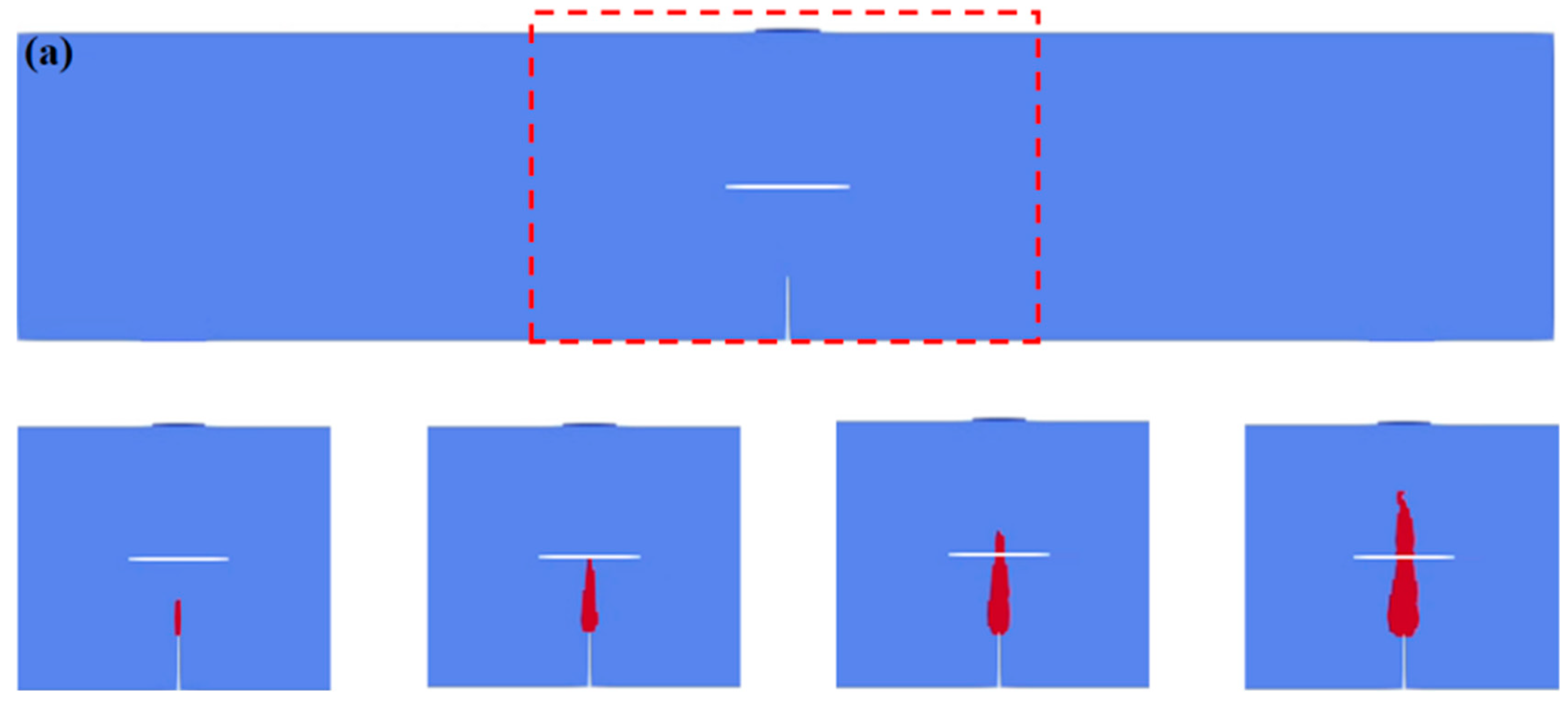
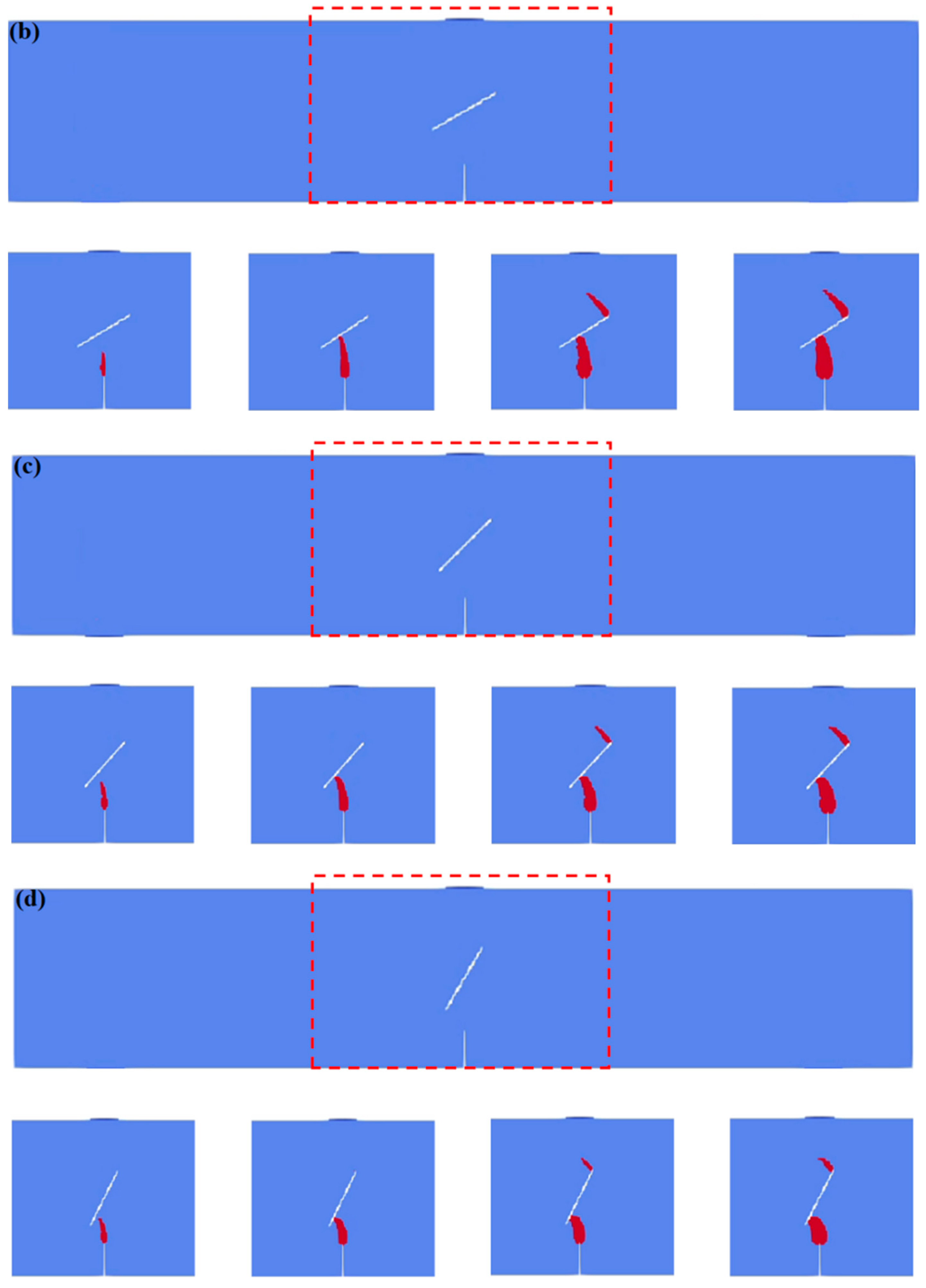
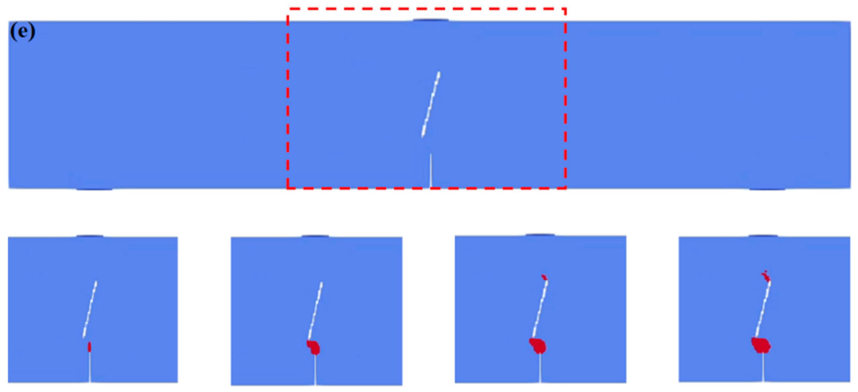
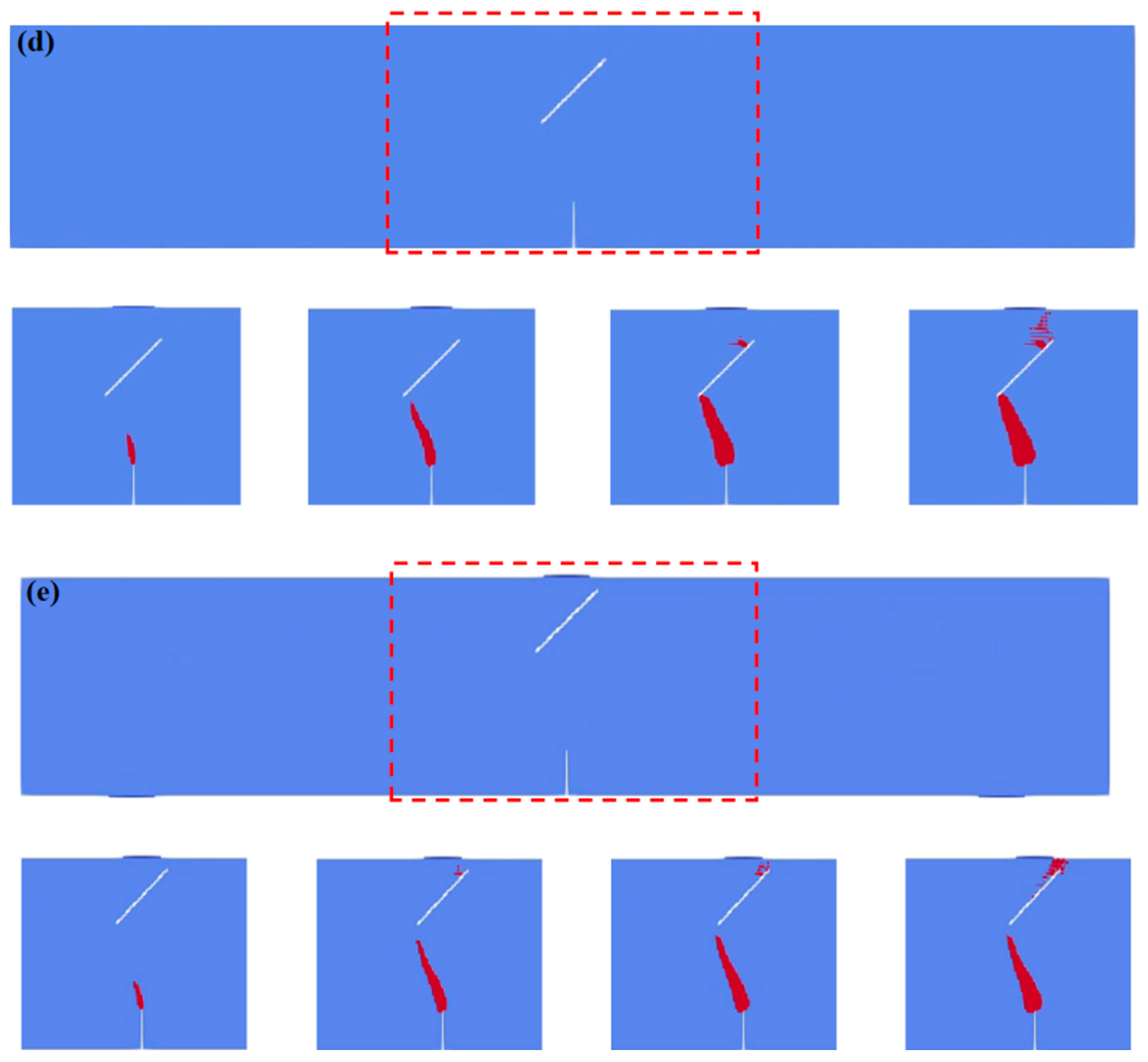
Figure 3 shows the three-point-bending crack propagation process of concrete beams under different obstacle fissure angles (Scheme A). For Scheme A1 (α = 0°), after the crack initiates at the tip of the guide fissure, it propagates along the loading direction and laps with the obstacle fissure. As the load increases, no new cracks appear, and the original crack continues to extend toward the top loading point until it penetrates the model and fails.
For Scheme A2 (α = 30°), the crack initiates at the tip of the guide fissure, and its propagation path deviates from the vertical upward direction due to the “attraction” of the obstacle fissure, tending to the direction perpendicular to the obstacle fissure and lapping with it. Due to the increase in the obstacle fissure angle α, the lapping position of the crack and the obstacle crack migrates to the lower left end of the obstacle fissure, the crack propagation length shows a decreasing trend, and the lapping time is correspondingly shortened. After the load increases, a new crack forms at the right end of the obstacle fissure and extends toward the top loading point, but this crack is relatively short, and finally, the model is penetrated and fails.
For Scheme A3 (α = 45°), the crack that initiates at the tip of the induced fissure deviates from the vertical direction due to the “attraction” of the obstacle fissure during propagation, and laps with the obstacle fissure in the direction perpendicular to the obstacle fissure. At this time, the migration degree of the lapping position to the lower left end of the obstacle fissure, the decreasing range of the crack propagation length, and the shortening degree of the lapping time are all between α = 30° and α = 60°. After the load increases, a new crack at the right end of the obstacle fissure extends toward the top loading point, and this crack tends to be short, finally penetrating the model and failing.
For Scheme A4 (α = 60°), after the crack initiates at the tip of the guide fissure, it deviates from the vertical propagation direction under the influence of the obstacle fissure, tends to the direction perpendicular to the obstacle fissure, and laps with it. The migration degree of the lapping position to the lower left end of the obstacle fissure is larger than that at α = 45°, the crack propagation length is shorter, and the lapping time is shorter. When the load increases, a new crack at the right end of the obstacle fissure extends toward the top loading point, and this crack is shorter, finally penetrating the model and failing.
For Scheme A5 (α = 75°), the crack that initiates at the tip of the induced fissure significantly deviates from the vertical direction due to the “attraction” of the obstacle fissure during propagation, tends to the direction perpendicular to the obstacle fissure, and laps with it. At this time, the migration degree of the lapping position at the lower left end of the obstacle fissure is the largest, the crack propagation length is the shortest, and the lapping time is the shortest. As the load increases, a new crack at the right end of the obstacle fissure extends toward the top loading point, and this crack is the shortest, finally penetrating the model and failing.

5.2. Influence of Different Obstacle Fissure Spacings on Fissure Interaction in Concrete Beams

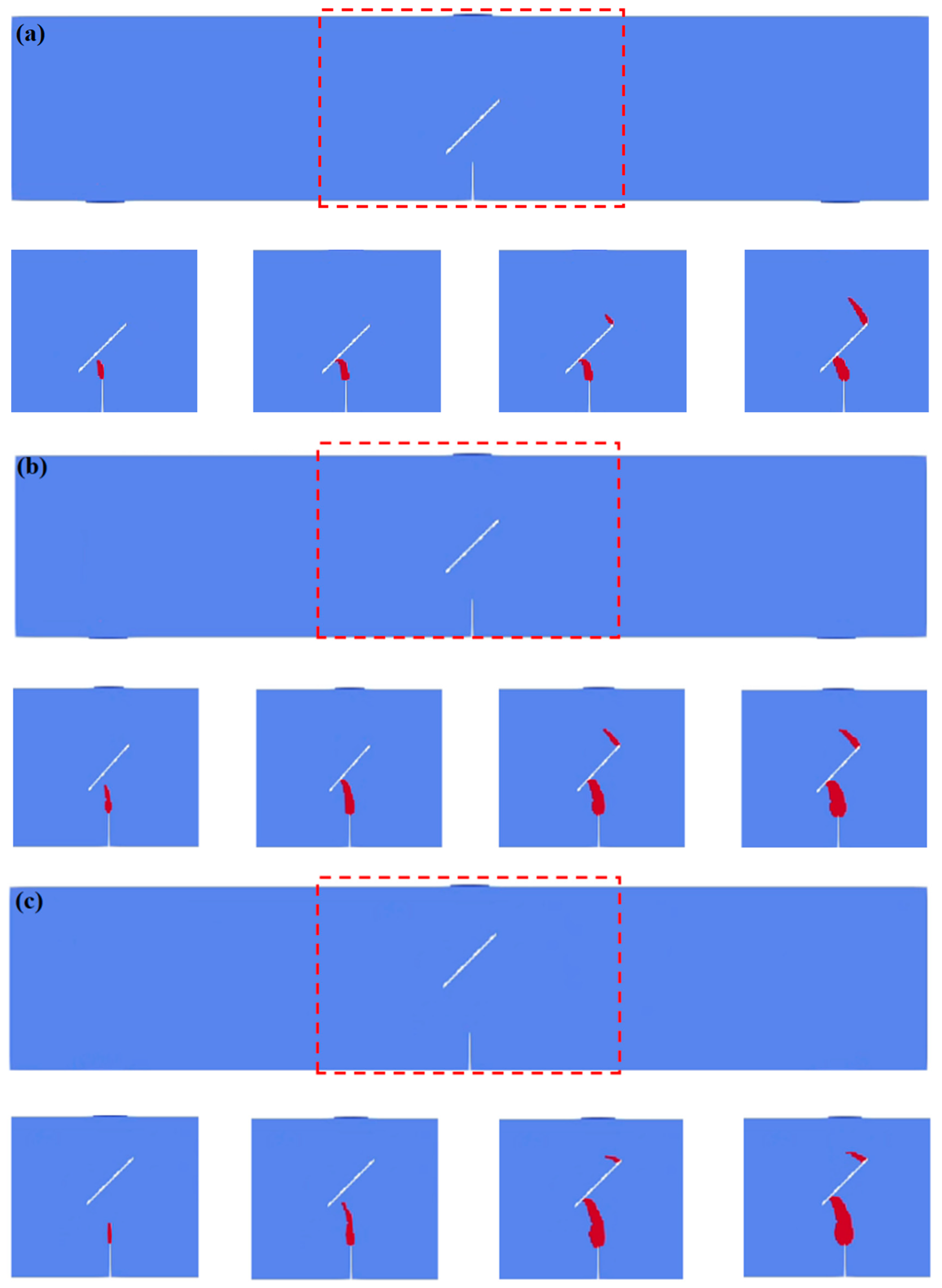
Figure 4 shows the three-point-bending crack propagation process of concrete beams under different obstacle fissure spacings (Scheme B). For Scheme B1 (d = 0.02 m), after the crack initiates at the tip of the induced fissure, it propagates vertically along the loading direction, deviating from its original path due to the “attraction” of the obstacle fissure, and laps with the obstacle fissure. As the load continues to increase, a new crack is generated at the right end of the obstacle fissure and extends toward the top loading point, which finally penetrates the model and causes failure.
For Scheme B2 (d = 0.03 m), the crack initiates at the tip of the guide fissure, and its propagation path deviates from the vertical upward direction due to the “attraction” of the obstacle fissure, and then laps with the obstacle fissure. It is worth noting that compared with the case of d = 0.02 m, the lapping position of the crack and the obstacle fissure moves to the lower left end of the obstacle fissure, and the lapping time is prolonged. As the load increases, a new crack appears at the right end of the obstacle fissure and extends toward the top loading point, which tends to extend toward the top loading point, and finally penetrates the model.
For Scheme B3 (d = 0.04 m), after the crack initiates, it deviates from the vertical propagation direction and laps with the obstacle fissure under the influence of the obstacle fissure. The lapping position further moves to the lower left end of the obstacle fissure, and the lapping time is longer than that at d = 0.03 m. After the load increases, a new crack forms at the right end of the obstacle fissure and extends toward the top loading point, which has a more obvious trend of horizontal extension to the left, and finally penetrates the model.
For Scheme B4 (d = 0.05 m), the crack that initiates at the tip of the induced fissure deviates from the vertical direction and laps with the obstacle fissure under the “attraction” of the obstacle fissure during propagation. The lapping position continues to move to the lower left end of the obstacle fissure, and the lapping time is further increased. As the load increases, a new crack at the right end of the obstacle fissure extends toward the top loading point, which has a significant leftward horizontal extension characteristic, and finally penetrates the model.
For Scheme B5 (d = 0.06 m), after the crack initiates at the tip of the guide fissure, it deviates from the vertical propagation direction and laps with the obstacle fissure under the action of the obstacle fissure. At this time, the lapping position is the largest at the lower left end of the obstacle fissure, and the lapping time is the longest. When the load increases, the new crack at the right end of the obstacle fissure has a strong leftward horizontal extension trend and obviously extends toward the top loading point, finally penetrating the model.

6. Discussion

6.1. Crack Initiation Mechanism Under Different Obstacle Fissure Angles

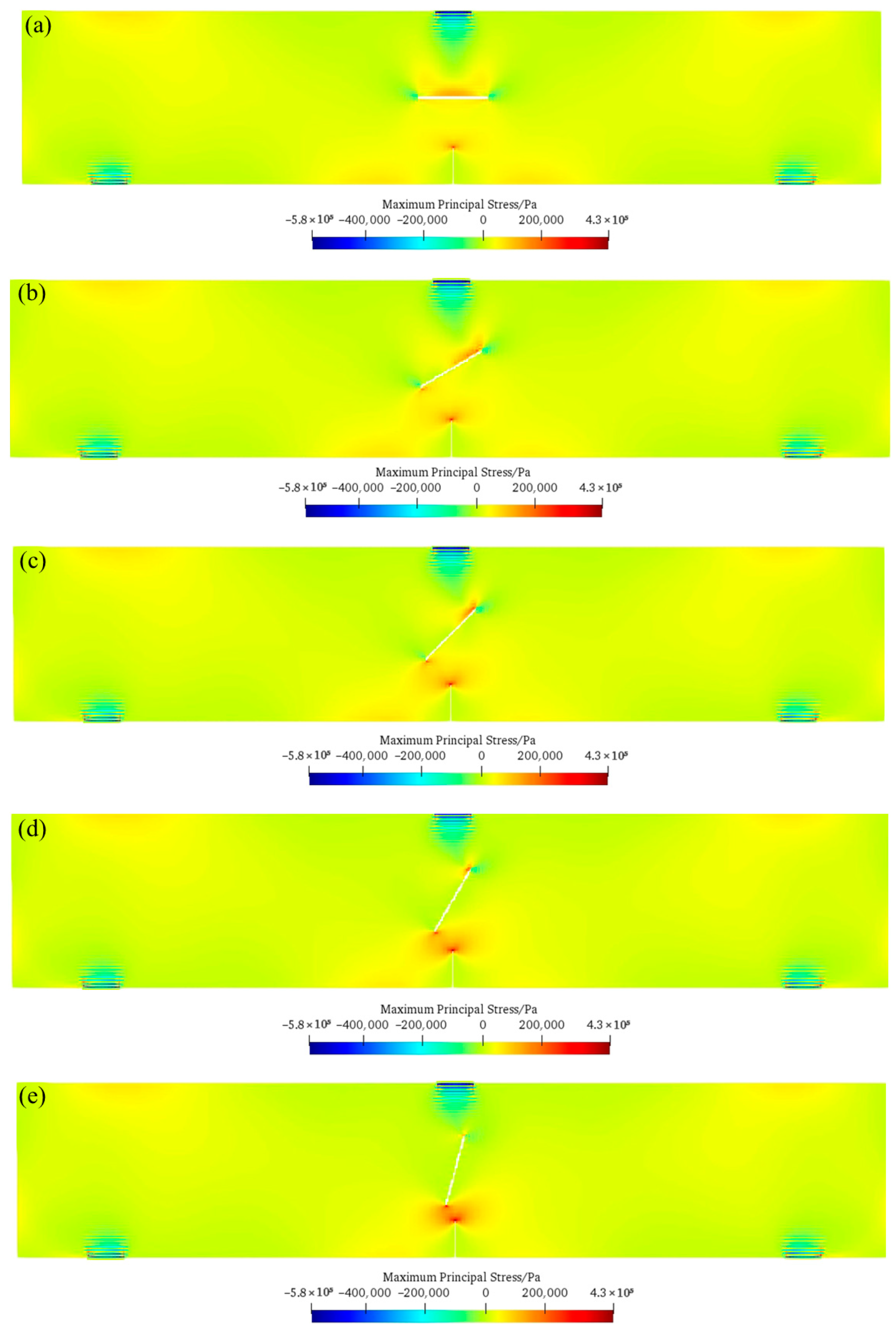
Figure 5 shows the maximum principal stress distribution law of the concrete model under different obstacle fissure angles. It can be seen that when the obstacle fissure angle is 0°, a significant tensile stress concentration occurs at the tip of the induced fissure and the middle part of the obstacle fissure. Between them, the stress concentration at the tip of the induced fissure promotes crack initiation at this position first, and the stress distribution in the middle part of the obstacle fissure makes the crack propagate vertically toward the loading point, finally forming a through failure. The crack propagation path in this stage is relatively regular, mainly dominated by the vertical load. As the obstacle fissure angle gradually increases from 0° to 30° and 45°, the tensile stress concentration area begins to transfer from the middle part of the obstacle fissure to its two ends. At this time, the crack that initiates at the tip of the induced fissure no longer propagates in the vertical direction but is “attracted” by the tensile stress concentration at the lower end of the obstacle fissure and gradually deflects toward the lower end of the obstacle fissure. After the crack laps with the obstacle fissure, the tensile stress concentration at the upper tip of the obstacle fissure causes the new crack to extend toward the top loading point of the model, forming a through path of “induced fissure—obstacle fissure—top”. The deflection degree of the crack propagation path in this stage increases with an increase in the angle, and a stress concentration difference at both ends of the obstacle fissure gradually appears. When the obstacle fissure angle further increases to 60° and 75°, the tensile stress concentration degree at the lower tip of the obstacle fissure is significantly enhanced, while the tensile stress concentration at the upper tip gradually weakens. This stress distribution characteristic makes a crack initiate at the tip of the induced fissure and then expand directly to the lower tip of the obstacle fissure with a larger deflection angle, and the lapping time and expansion length are significantly shortened. At the same time, although a crack is still initiated at the upper tip of the obstacle fissure, the crack propagation length is shorter due to the decrease in the stress concentration. The final failure mode shows that the crack first penetrates from the lower tip of the obstacle fissure to the top of the model, indicating that a larger obstacle fissure angle will cause the lower part of the structure to fail first, which is significantly different from the failure mechanism under a low angle. To sum up, the obstacle fissure angle regulates the crack initiation position and propagation path by changing the position and strength of tensile stress concentration, and the larger the angle is, the more likely it is that the lower part of the obstacle fissure will become the key area leading to failure.

6.2. Crack Initiation Mechanism Under Different Obstacle Fissure Spacings

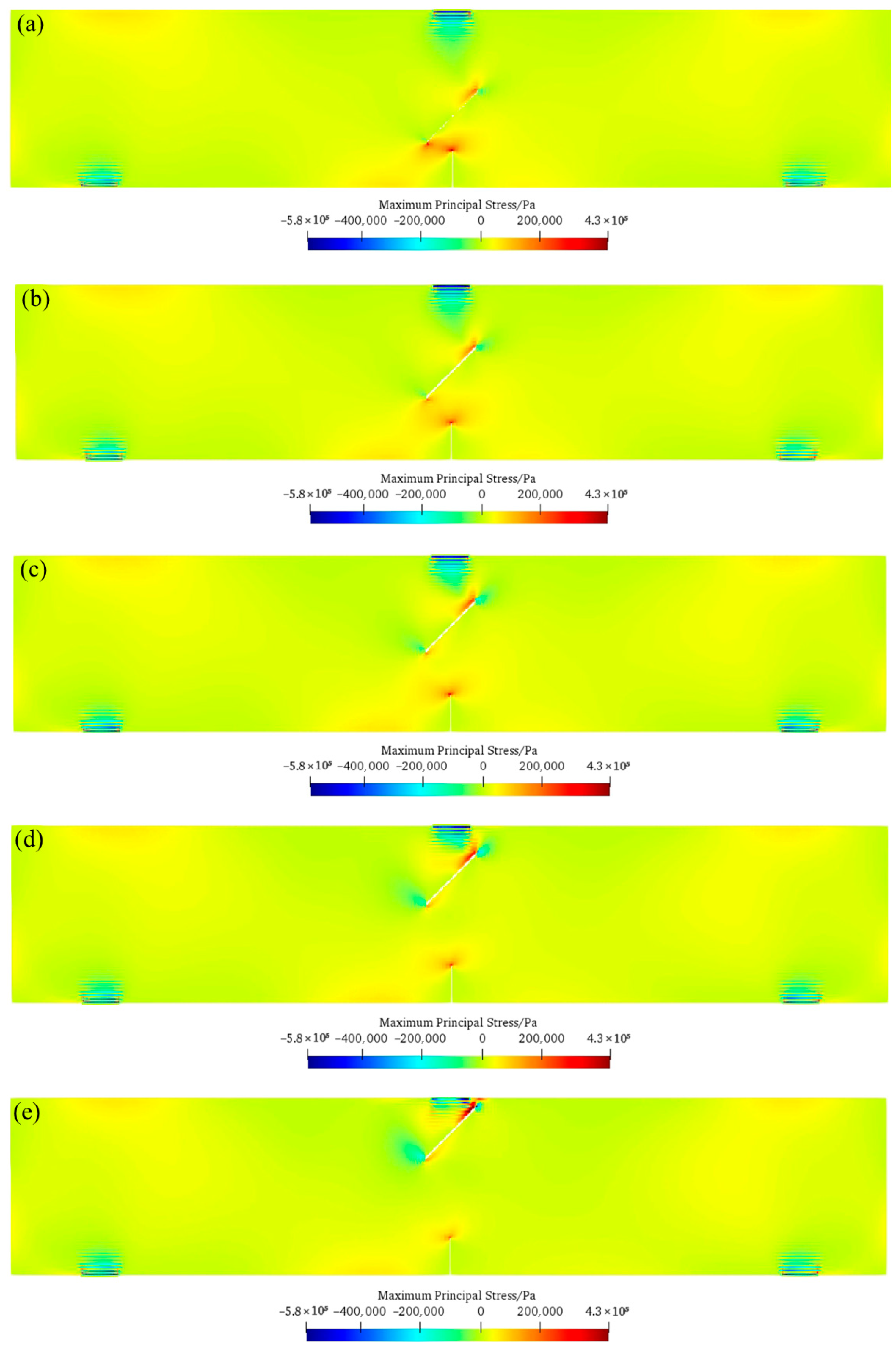
Figure 6 shows the maximum principal stress distribution law of the concrete model under different obstacle fissure spacings. When the obstacle fissure spacing is small (such as d = 0.02 m), a significant tensile stress concentration occurs at the tip of the induced fissure and at both ends of the obstacle fissure. Among them, the high stress state at the tip of the induced fissure promotes a crack to initiate here first, and the stress concentration at both ends of the obstacle fissure leads to the vertical propagation of the crack along the loading direction and the rapid lapping with the obstacle fissure, forming a through failure path. At this time, the tensile stress concentration degree at the lower end of the obstacle fissure is significantly higher than that at the upper end, the crack propagation path is dominated by the lower-end stress, and shows the obvious characteristics of “vertical propagation—lower end lapping of obstacle fissure”. As the obstacle fissure spacing gradually increases from 0.02 m to 0.03 m and 0.04 m, the tensile stress concentration degree at the tip of the induced fissure gradually weakens, while the tensile stress concentration at the upper end of the obstacle fissure begins to increase. In this stage, after a crack initiates at the tip of the induced fissure, the trend of its expansion path deflecting to the lower end of the obstacle fissure due to the “attraction effect” of the obstacle fissure weakens, the lapping position gradually migrates to the lower left end of the obstacle fissure, and the lapping time required is prolonged. For example, when d = 0.03 m, the crack needs to pass through a longer path to lap with the obstacle fissure, and the stress concentration at the upper end of the obstacle fissure begins to cause the new crack to extend toward the top loading point, but at this time, the lower-end stress still dominates the overall direction of crack propagation. When the obstacle fissure spacing further increases to 0.05 m and 0.06 m, the tensile stress concentration at the tip of the induced fissure is significantly reduced, while the tensile stress concentration degree at the upper end of the obstacle fissure is significantly enhanced, and the lower-end stress concentration is further weakened. This stress distribution change makes the crack initiate at the tip of the induced fissure and then its expansion path tends to deflect to the upper end of the obstacle fissure, and the lapping position continues to move to the lower left end of the obstacle fissure. For example, when d = 0.06 m, the crack needs to pass through a longer horizontal expansion stage to lap with the obstacle fissure, and the high stress state at the upper end of the obstacle fissure promotes the new crack to extend toward the top loading point with a more obvious horizontal expansion trend, finally forming a through path of “induced fissure—upper end of obstacle fissure—top”. Combined with the simulation results in 5.2, it can be seen that with an increase in the obstacle fissure spacing, the lapping position of the crack and the obstacle fissure continues to migrate to its lower left end, the lapping time is gradually increased, and the horizontal expansion characteristics of the new crack at the right end of the obstacle fissure are more and more obvious. This indicates that the obstacle fissure spacing regulates the crack initiation position and propagation path by changing the stress superposition effect between the induced fissure and the obstacle fissure—the smaller the spacing is, the stronger the stress coupling effect between the induced fissure and the obstacle fissure is, and the crack propagation is more dependent on the lower-end stress concentration; the larger the spacing is, the more obvious the stress-dominant role at the upper end of the obstacle fissure is, the horizontal component of the crack propagation path is gradually enhanced, and finally, the structure failure mode changes from “lower end dominated” to “upper end dominated”.

6.3. Comparisons Between Numerical Results and Previous Experimental Results

Figure 7 shows the comparisons between the numerical results and previous experimental results [46]. As can be seen, the crack propagation paths are similar, which validates the rationality of the proposed method.

6.4. Application Prospects of SPH Method to Simulation of Concrete Multi-Fissure Interaction

Compared with the traditional finite element method and discrete element method, the SPH method has significant advantages for the simulation of concrete multi-fissure interaction. It overcomes the mesh dependency; can naturally handle discontinuous problems, such as crack initiation, propagation, and bifurcation; the parameters have clear physical meanings, directly corresponding to the macroscopic material properties, reducing the difficulty of model debugging; and in the dynamic and static load coupling scenarios, it can efficiently handle the stress wave propagation and energy dissipation, avoiding calculation divergence.
However, the current SPH has certain limitations in the three-dimensional simulation of concrete multi-fissures. Its three-dimensional crack characterization ability is insufficient, and it cannot fully reflect the three-dimensional crack network of concrete in actual engineering; its characterization of material heterogeneity is simplified, and it is difficult to accurately simulate the crack propagation mechanism of an aggregate–mortar interface transition zone; and when dealing with the energy release rate of crack propagation, simplified fracture criterion is adopted, which may lead to a deviation between the simulation results and the actual test.
In order to promote the development of the SPH method, the following improvement directions could be pursued in the future: expand and verify the three-dimensional SPH model; introduce three-dimensional particle discrete technology; construct a model combined with CT scan data, and verify it by comparing it with the three-dimensional fracture test; realize multi-physical field coupling and material heterogeneity improvement; integrate the relevant models to simulate a multi-physical field interaction; combine it with other methods to characterize the crack deflection mechanism of heterogeneous materials; refine the fracture energy and dynamic failure model; improve the application of relevant laws; introduce dynamic fracture criterion; and develop composite failure criterion.
If the above bottlenecks could be broken through, the SPH method could play a key role in hydraulic structure scenarios, such as crack prevention and control of concrete dams, anti-crack design of underground caverns, and durability evaluations of coastal structures, and could be expected to become the core tool for the simulation of hydraulic concrete multi-fissure interaction. However, it still needs to further improve its application to three-dimensional heterogeneous and multi-field coupling scenarios through model improvements and test verification.

7. Conclusions

(1)
Aiming at the limitations of traditional SPH methods for handling the interaction of multiple fissures in concrete, the control equations were improved, and a particle progressive failure processing mechanism was introduced. By introducing the failure parameter ξ and improving the kernel function K, and combining them with the Mohr–Coulomb criterion, the simulation of the SPH particle failure process was realized. A meshless numerical model for the three-point bending of a concrete beam with double slits was established, and the interactive propagation process of cracks was successfully simulated, providing an effective numerical analysis method for revealing the evolution mechanism of concrete crack propagation.
(2)
The change in the obstacle fissure angle α directly regulates the crack initiation position and propagation path. When α = 0°, the crack initiates at the tip of the induced fissure and then propagates in the vertical direction to lap with the middle part of the obstacle fissure. As α increases to 30–75°, the tensile stress concentration transfers from the middle part of the obstacle fissure to both ends, the crack gradually deflects toward the lower end of the obstacle fissure, the lapping position migrates to its lower left end, and the propagation length shortens with a reduced lapping time. When α = 75°, the tensile stress concentration at the lower tip of the obstacle fissure is significantly enhanced, and the lower part of the structure fails first, presenting a through mode of “induced fissure–lower end of obstacle fissure–top”.
(3)
Under three-point bending loads, the obstacle fissure spacing d regulates crack propagation by changing the stress superposition effect. When d is small (e.g., 0.02 m), the tensile stress concentration at the tip of the induced fissure and at both ends of the obstacle fissure is significant, and the crack propagates vertically and rapidly laps with the lower end of the obstacle fissure. As d increases to 0.06 m, the tensile stress concentration at the tip of the induced fissure weakens, while the stress concentration at the upper end of the obstacle fissure is enhanced. The crack propagation path deflects toward the upper end of the obstacle fissure, the lapping position continues to migrate to the lower left end, and the horizontal propagation characteristic becomes more obvious, with the failure mode changing from “lower-end dominated” to “upper-end dominated”.
(4)
Compared with the finite element method and discrete element method, the SPH method has advantages, such as no mesh dependency; clear physical meanings of parameters; and strong adaptability to dynamic loading, which can effectively simulate the processes of crack initiation, propagation, and bifurcation. In the future, it will be necessary to further expand the three-dimensional SPH model, construct heterogeneous models with aggregates combined with CT scans, integrate multi-physical field coupling mechanisms, and improve the fracture energy dissipation model. This method is expected to become a core simulation tool in hydraulic engineering fields, such as crack prevention and control of concrete dams, anti-crack design of underground caverns, and durability evaluations of coastal structures, but it needs to be improved through experimental verification before application to three-dimensional heterogeneous scenarios.

Author Contributions

Methodology, H.Z.; investigation, H.Z., Y.S., D.N., Y.X., D.Q., B.Z., W.L. and S.Y.; writing—original draft preparation, H.Z., Y.S. and S.Y.; writing—review and editing, S.Y. All authors have read and agreed to the published version of the manuscript.

Funding

This research work was financially supported by the Ningxia Hui Autonomous Region Water Resources Science and Technology Project (No. HLSDL-KY-2024-001).

Data Availability Statement

Data will be made available on reasonable request.

Conflicts of Interest

The authors declare no conflict of interest.

References

  1. Yu, S.; Sun, Z.; Yu, J.; Yang, J.; Zhu, C. An improved meshless method for modeling the mesoscale cracking processes of concrete containing random aggregates and initial defects. Constr. Build. Mater. 2023, 363, 129770. [Google Scholar] [CrossRef]
  2. Yu, S.; Huang, S.; Li, Y.; Liang, Z. Insights into the frost cracking mechanisms of concrete by using the coupled thermo-hydro-mechanical-damage meshless method. Theor. Appl. Fract. Mech. 2025, 136, 104814. [Google Scholar] [CrossRef]
  3. Pan, J.; Xiong, S. Deformation, failure and restoration of the Trier arch dam in Switzerland. Dam Saf. 1987, 1, 2–22. [Google Scholar]
  4. Zhu, B. Re-discussion on the cause of fracture during construction of Xiaowan arch dam. Water Resour. Hydropower Eng. 2015, 46, 1–5. [Google Scholar]
  5. Ru, N.; Jiang, Z. Dam Accidents and Safety Arch Dams; China Water Resources and Hydropower Press: Beijing, China, 1995. [Google Scholar]
  6. Guo, W.; Yan, S.; Gao, G. Electro-Chemo-Mechanical coupled model for corrosion and crack propagation in reinforced concrete. J. Build. Eng. 2025, 108, 112988. [Google Scholar] [CrossRef]
  7. Wang, H.; Jia, M.; Yang, X.; Wang, Y.; Yu, R.C.; Wu, Z. Determination of fracture toughness of concrete based on actual critical crack length: Theoretical model and experimental validation. Eng. Fract. Mech. 2025, 318, 110966. [Google Scholar] [CrossRef]
  8. Zhu, X.; Zhang, Z.; Feng, Y.; Yu, H. Meso-crack propagation of RC induced by non-uniform rebar corrosion and the predictive model of time to concrete cover cracking. Eng. Fail. Anal. 2024, 166, 108831. [Google Scholar] [CrossRef]
  9. Lei, J.; Xu, C.; Lü, C.; Feng, Q.; Zhang, H. A data-driven prediction for concrete crack propagation path based on deep learning method. Case Stud. Constr. Mater. 2024, 21, e03883. [Google Scholar] [CrossRef]
  10. Yousef, A.; Spyridis, P. Probabilistic analysis of cracking in concrete floor slabs under seismic loading and interactions with Power Actuated Fasteners (PAF). Structures 2025, 78, 109230. [Google Scholar] [CrossRef]
  11. Wang, D.; Tang, J. Assessment of thermal cracking and damage in concrete by ultrasonic velocity and Vp/Vs ratio. Cem. Concr. Res. 2025, 196, 107929. [Google Scholar] [CrossRef]
  12. Jia, M.; Wu, Z.; Jiang, X.; Yu, R.C.; Zhang, X.; Wang, Y. Modified Paris law for mode I fatigue fracture of concrete based on crack propagation resistance. Theor. Appl. Fract. Mech. 2024, 131, 104383. [Google Scholar] [CrossRef]
  13. Fan, C.; Ding, Y.; Liu, X.; Yang, K. A review of crack research in concrete structures based on data-driven and intelligent algorithms. Structures 2025, 75, 108800. [Google Scholar] [CrossRef]
  14. Wang, X.; Li, J.; Zhao, X.; Liang, Y. Propagation characteristics and prediction of blast-induced vibration on closely spaced rock tunnels. Tunn. Undergr. Space Technol. 2022, 123, 104416. [Google Scholar] [CrossRef]
  15. Xiao, W. Analytical theory on instability sliding of surrounding rock blocks in tunnel roof under stress wave actions. Chin. J. Theor. Appl. Mech. 2024, 56, 183–197. [Google Scholar]
  16. Wang, J.R.; Deng, J.; Ren, S.J.; Qu, G.Y.; Wang, C.P.; Guo, R.Q.; Zhao, X.Q. Acoustic wave propagation characteristics and spontaneous combustion warning of coal during oxidative warming of loose coal. Fuel 2025, 398, 135528. [Google Scholar] [CrossRef]
  17. Wang, Y.J.; Zeng, M.H.; Liu, H.B.; Yang, J.Q.; Li, X.X.; Hu, X. A comparative study of nil-SIF-based and initial fracture toughness-based criteria for prediction of mode-I crack propagation in concrete at low temperatures. Eng. Fract. Mech. 2025, 317, 110909. [Google Scholar] [CrossRef]
  18. Dong, W.; Wu, Z.; Zhou, X.; Wang, N.; Kastiukas, G. An experimental study on crack propagation at rock-concrete interface using digital image correlation technique. Eng. Fract. Mech. 2017, 171, 50–63. [Google Scholar] [CrossRef]
  19. Chen, B.; Yu, H.; Zhang, J.; Ma, H. Evolution law of crack propagation and crack mode in coral aggregate concrete under compression: Experimental study and 3D mesoscopic analysis. Theor. Appl. Fract. Mech. 2022, 122, 103663. [Google Scholar] [CrossRef]
  20. Li, D.; Huang, P.; Chen, Z.; Yao, G.; Guo, X.; Zheng, X.; Yang, Y. Experimental study on fracture and fatigue crack propagation processes in concrete based on DIC technology. Eng. Fract. Mech. 2020, 235, 107166. [Google Scholar] [CrossRef]
  21. Zhang, J.; Dong, W.; Zhang, B. Experimental study on local crack propagation of concrete under three-point bending. Constr. Build. Mater. 2023, 401, 132699. [Google Scholar] [CrossRef]
  22. Nie, Z.; Yu, L.; Zhu, P.; Wu, N.; Zuo, D.; Gan, X. Experimental study on nonlinear ultrasonic characterization of concrete during crack propagation. J. Eng. Res. 2023, 11, 314–321. [Google Scholar] [CrossRef]
  23. Zeng, M.-H.; Wang, H.-W.; Wang, Y.-J.; Zheng, J.-J.; Wu, Z.-M. Meso-crack propagation process of concrete based on macro-fracture parameters: Numerical and experimental. Theor. Appl. Fract. Mech. 2024, 129, 104216. [Google Scholar] [CrossRef]
  24. Min, Q.; Li, M.; Zhang, M.; Lian, H.; Jacquemin, T.; Bordas, S.P.A. Node projection strategy for FEM simulating cross-scale crack propagation in massive concrete structures. Eng. Struct. 2023, 293, 116665. [Google Scholar] [CrossRef]
  25. Yang, S.T.; Li, K.F.; Li, C.Q. Numerical determination of concrete crack width for corrosion-affected concrete structures. Comput. Struct. 2018, 207, 75–82. [Google Scholar] [CrossRef]
  26. Lei, Y.; Yang, X.; Liu, Q. An enhanced polar-based GPGPU-parallelized contact detection algorithm for 3D FDEM and its application to cracking analysis of shield tunnel segmental linings. Tunn. Undergr. Space Technol. 2024, 148, 105782. [Google Scholar] [CrossRef]
  27. Wu, Y.; Wang, D.; Wu, C.-T. Three dimensional fragmentation simulation of concrete structures with a nodally regularized meshfree method. Theor. Appl. Fract. Mech. 2014, 72, 89–99. [Google Scholar] [CrossRef]
  28. Nitka, M.; Rucka, M. 3D DEM modelling of acoustic emission in concrete: Insights into elastic waves initiated by microcracks. Ultrasonics 2025, 150, 107599. [Google Scholar] [CrossRef]
  29. Nitka, M.; Tejchman, J. Mesoscopic simulations of a fracture process in reinforced concrete beam in bending using a 2D coupled DEM/micro-CT approach. Eng. Fract. Mech. 2024, 304, 110153. [Google Scholar] [CrossRef]
  30. Wang, Y.; Li, M.; Chen, M.; Zhao, Z.; Zhu, F.; Jiang, Y.; Ren, J. Synergistic effects of aggregate-void distribution on low-temperature fracture performance and crack propagation of asphalt concrete under mode I and mode II fracturing. Eng. Fract. Mech. 2024, 307, 110352. [Google Scholar] [CrossRef]
  31. Zhang, Q.; Feng, C.; Wang, D.; Wu, Z.; Yang, L.; Yue, J. Investigation on the dynamic failure characteristics of concrete slab based on mesoscopic simulation and energy conversion analysis. Case Stud. Constr. Mater. 2024, 21, e03661. [Google Scholar] [CrossRef]
  32. Yang, X.; Xiang, J.; Latham, J.-P.; Naderi, S.; Wang, Y. Cracking and fragmentation in percussive drilling:Insight from FDEM simulation. J. Rock Mech. Geotech. Eng. 2025. [Google Scholar] [CrossRef]
  33. Tang, Z.-Q.; Yin, Z.-Y.; Jin, Y.-F.; Zhou, X.-W. A novel mesoscale modelling method for steel fibre-reinforced concrete with the combined finite-discrete element method. Cem. Concr. Compos. 2024, 149, 105479. [Google Scholar] [CrossRef]
  34. Wang, Y.; Xiong, Z.; Kou, L. Analysis of crack propagation in tunnel lining based on nonlinear dual-parameter bond-based peridynamics model. Structures 2025, 75, 108846. [Google Scholar] [CrossRef]
  35. Wang, G.; Lu, D.; Gao, Y.; Xie, Z.; Du, X. Viscoelastic peridynamic method for the interface in the reinforced concrete. Eng. Fract. Mech. 2025, 315, 110817. [Google Scholar] [CrossRef]
  36. Jin, Y.; Li, L.; Jia, Y.; Shao, J.; Rougelot, T.; Burlion, N. Numerical study of shrinkage and heating induced cracking in concrete materials and influence of inclusion stiffness with Peridynamics method. Comput. Geotech. 2021, 133, 103998. [Google Scholar] [CrossRef]
  37. Yu, S.; Wang, J.; Gao, Y. Effects of fissure properties on the tunnel damage evolutions: Insights from DIC-based 3D printing experiments and meshless numerical simulations. Tunn. Undergr. Space Technol. 2024, 149, 105817. [Google Scholar] [CrossRef]
  38. Xiang, Z.; Yu, S.; Wang, X. Modeling the Hydraulic Fracturing Processes in Shale Formations Using a Meshless Method. Water 2024, 16, 1855. [Google Scholar] [CrossRef]
  39. Hu, X.; Yu, S.; Gao, Y. Experimental and meshless numerical simulation on the crack propagation processes of marble SCB specimens. Eng. Fract. Mech. 2024, 308, 110354. [Google Scholar] [CrossRef]
  40. Hu, X.; Yu, S.; Ying, P. Effects of fissure locations on the crack propagation morphologies of 3D printing tunnel models: Experiments and numerical simulations. Theor. Appl. Fract. Mech. 2024, 133, 104631. [Google Scholar] [CrossRef]
  41. Yu, S.; Gao, Y. A total Lagrange meshless method for modeling the concrete damage evolutions under blast loading. Comput. Part. Mech. 2024, 12, 491–508. [Google Scholar] [CrossRef]
  42. Wang, S.; Yu, S.; Ren, Z. Modelling the blast cracking processes of rock masses using a total lagrange meshless method. Case Stud. Constr. Mater. 2024, 21, e03673. [Google Scholar] [CrossRef]
  43. Wang, S.; Yu, S.; Hu, X. Effects of folded fissure properties on tunnel model failure: Experiments and numerical simulations. Eng. Fract. Mech. 2024, 310, 110487. [Google Scholar] [CrossRef]
  44. Hu, S.; Huang, S.; Yu, S.; Li, Y.; Dong, J. Investigations on the fracture mechanisms of Z-shaped fissured rock-like specimens. Theor. Appl. Fract. Mech. 2024, 134, 104748. [Google Scholar] [CrossRef]
  45. Yu, S.; Ren, X.; Zhang, J. Modeling the rock frost cracking processes using an improved ice—Stress—Damage coupling method. Theor. Appl. Fract. Mech. 2024, 131, 104421. [Google Scholar] [CrossRef]
  46. Wang, S.; Zhuang, M.; Xue, X. Experimental and Numerical Investigations on Crack Intersection and Propagation of Concrete Structures. Int. J. Concr. Struct. Mater. 2022, 16, 67. [Google Scholar] [CrossRef]
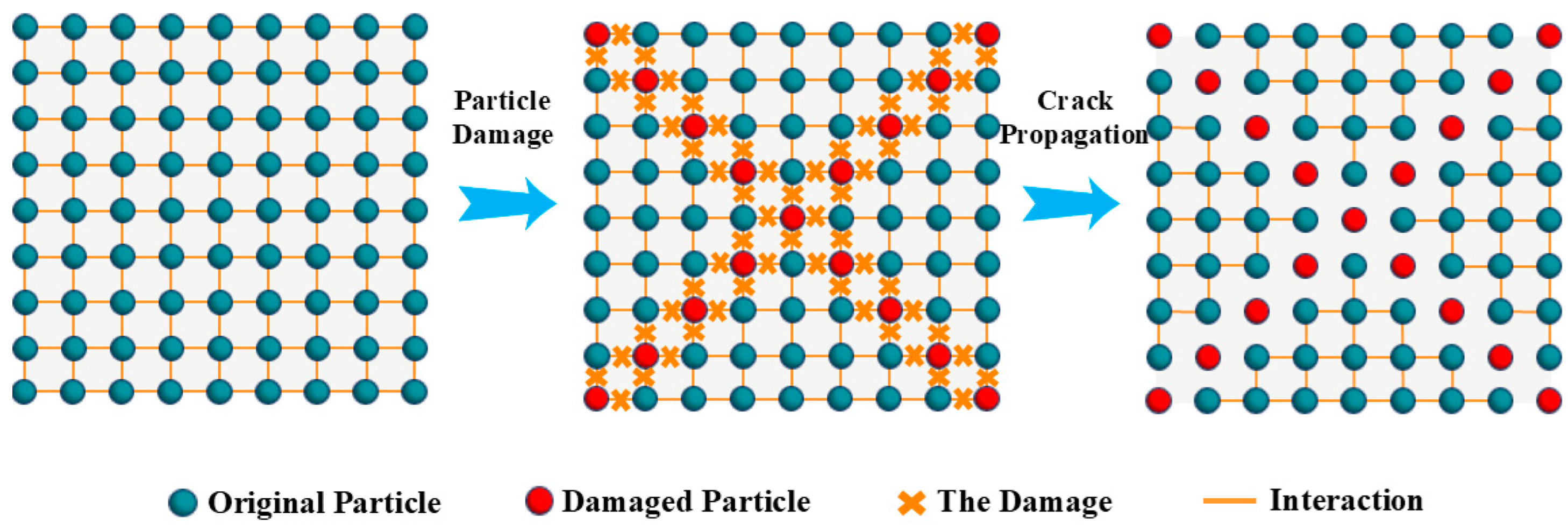
Figure 1. SPH particle failure schematic diagram.
Buildings 15 02898 g001
Figure 2. Numerical model and dimensions.
Buildings 15 02898 g002
Figure 3. Crack propagation laws of concrete beams under different inclination angles α of obstacle fissures: (a) α = 0°, (b) α = 30°, (c) α = 45°, (d) α = 60°, (e) α = 75°.
Buildings 15 02898 g003aBuildings 15 02898 g003bBuildings 15 02898 g003c
Figure 4. Crack propagation law of concrete beams under different crack spacings of obstacles: (a) d = 0.02 m, (b) d = 0.03 m, (c) d = 0.04 m, (d) d = 0.05 m, (e) d = 0.06 m.
Buildings 15 02898 g004aBuildings 15 02898 g004b
Figure 5. Distribution law of maximum principal stress of concrete models under different inclination angles of obstacle fractures: (a) α = 0°, (b) α = 30°, (c) α = 45°, (d) α = 60°, (e) α = 75°.
Buildings 15 02898 g005
Figure 6. Distribution law of maximum principal stress of concrete models under different fissure spacings of obstacles: (a) d = 0.02 m, (b) d = 0.03 m, (c) d = 0.04 m, (d) d = 0.05 m, (e) d = 0.06 m.
Buildings 15 02898 g006
Figure 7. Comparisons between the numerical results and previous experimental results. (a) Numerical results, (b) previous experimental results [46].
Buildings 15 02898 g007
Table 1. Calculation schemes.
SchemeDetailsSchemeDetails
A1α = 0°B1d = 20 mm
A2α = 30°B2d = 30 mm
A3α = 45°B3d = 40 mm
A4α = 60°B4d = 50 mm
A5α = 75°B5d = 60 mm
Disclaimer/Publisher’s Note: The statements, opinions and data contained in all publications are solely those of the individual author(s) and contributor(s) and not of MDPI and/or the editor(s). MDPI and/or the editor(s) disclaim responsibility for any injury to people or property resulting from any ideas, methods, instructions or products referred to in the content.