1. Introduction
With the accelerated transformation of the global construction industry in the direction of industrialization, intelligence, and low carbonization, prefabricated buildings are gradually becoming an important direction for the modernization of the construction industry with their advantages [
1,
2,
3]. Compared with the traditional cast-in-place building form, the prefabricated building has the characteristics of high production quality, fast construction efficiency, and environmental friendliness [
4,
5,
6]. At present, many countries are vigorously promoting prefabricated buildings, and China’s policy on prefabricated buildings is to maintain a wide range of promotion [
7]. However, the current design method of prefabricated buildings is less standardized [
8,
9], and the template reuse rate of prefabricated components is not high. This leads to the design efficiency of the prefabricated structure being insufficient to meet the requirements of industrial design. Therefore, it is very important to establish a standardized design process and an efficient design method.
Standardization has been a crucial concept in architectural design since the mid-20th century. The authors of [
10] considered this, particularly in the context of prefabricated components such as reinforced concrete panels, used widely in mass housing projects across Europe and Asia between the 1960s and 1980s [
11]. This study builds upon these historical precedents, adapting the concept of standardization to modern BIM-based methods. Many scholars [
12,
13,
14] believe that standardized design is the core link in the process of prefabricated building design, but the current imperfect standardization is one of the important factors hindering the development of building industrialization. Effective standardization enhances both component quality and design productivity. CAI [
15] pointed out that the current standardized parts library is not scalable enough to adapt to the rapid iteration requirements of emerging technologies, such as intelligent construction and green materials, which hinders the dynamic optimization of the whole life cycle. Through research on the Industrial Foundation Class (IFC) standard and the analysis of the information needs of the project participants, GAO et al. [
16] proposed the construction scheme of the prefabricated building parts library based on the IFC standard and realized the design, production, transportation, and construction informatization of the assembly building project. DONG et al. [
17] proposed a modular and parametric design method of PC components based on Design For Manufacture and Assembly (DFMA) and introduced standardized design to better perform DFMA-oriented parametric design of PC components, which greatly improved the efficiency of design. Based on the modular design of prefabricated components, the above research introduces a standardized design process, which provides new ideas and methods for the design of prefabricated buildings and promotes the development of prefabricated buildings. However, the existing research focuses on the construction of a modular system at the macro level and lacks the standardized design process of specific components. The standardized design of specific components not only needs to consider the unity of geometric dimensions but also needs to combine the actual engineering factors such as connection node structure, transportation, and hoisting restrictions to form a systematic design criterion.
As one of the core technologies to promote building industrialization [
18,
19], Building Information Modeling (BIM) technology has become the core supporting tool for the efficient implementation of prefabricated buildings through its parametric modeling, collaborative design, life cycle management, and other characteristics and also provides help for the sustainability of the project [
20,
21,
22]. Prefabricated components are an important part of the design efficiency [
23], which plays an important role in all stages of the project [
24]. Based on BIM technology, designers have proposed the design method of the parts library [
25,
26]. By using the design method of a parts library, the design efficiency of prefabricated components can be improved. The design method of a parts library based on BIM has achieved certain results. CUI et al. [
27] proposed the method of a planar module library, which provided a new idea for the graphic design of prefabricated houses. CAO et al. [
28] proposed a graph-based approach to develop module libraries, which includes graphical representation of modules, graphical database development, and graph-based similarity analysis to support the storage, sharing, and reuse of module libraries. Based on Knowledge-Based Engineering (KBE), LI et al. [
29] established a modular design system. By selecting and recombining modules in the module library, new residential floor plans can be obtained. Pibal et al. [
30] introduced a comprehensive algorithm-aided BIM framework for modular residential building models, whereby parameterized modules are automatically combined based on structural and layout rules, offering a novel workflow for prefabricated housing design. Sobieraj et al. [
31] explored the implementation of BIM workflows in prefabricated modular construction (PFMC); the study demonstrated how integrating BIM into PFMC enhances efficiency, quality control, and automation at each stage. In summary, using the design method of a parts library can improve the efficiency of design.
However, most of the existing parts library design methods are aimed at the design of plane drawings, which cannot be well combined with BIM technology, thus forming a design of visibility, diversity, and synergy. The design idea still stays on the traditional design idea and is still designed based on the idea of splitting and then combining. Some research primarily focuses on generic prefabricated component libraries or macro-level modular systems, often lacking the depth of standardized design processes tailored to the intricate node connections, size coordination, and life cycle management requirements of specialized systems like the PCCWS.
To bridge these gaps, this study proposes a novel approach by establishing a comprehensive standardized design process specifically for PCCWS components and developing an integrated 3D parts library system built upon this foundation. The novelty of this work lies in the following: (1) its system-specific focus on PCCWS, providing detailed standardization rules for size, nodes, and coding directly applicable to this system; (2) the development of a dedicated 3D parts library system (implemented using MATLAB) that goes beyond generic repositories by embedding these PCCWS-specific standards and enabling efficient component management and retrieval; and (3) the integration of this library within a BIM workflow (PKPM-BIMBASE/Revit) for streamlined design, validation, and detailing, demonstrating significant efficiency gains.
Table 1 shows a comparison of the proposed 3D Parts Library PCCWS with existing global BIM object libraries.
Through the 3D parts library, the design of the structure can be completed quickly. Specifically, this study establishes a standardized design process based on the prefabricated components of PCCWS. The design method of a 3D parts library based on BIM was innovatively constructed. Taking a prefabricated concrete dormitory building as an example, the design method of 3D parts library based on BIM is applied, and the difference between it and the traditional design method is analyzed. It is expected that the results of this study can provide practical references for the design of prefabricated concrete composite wall-slab buildings, improve the standardization of prefabricated projects, and provide a good foundation for industrialization.
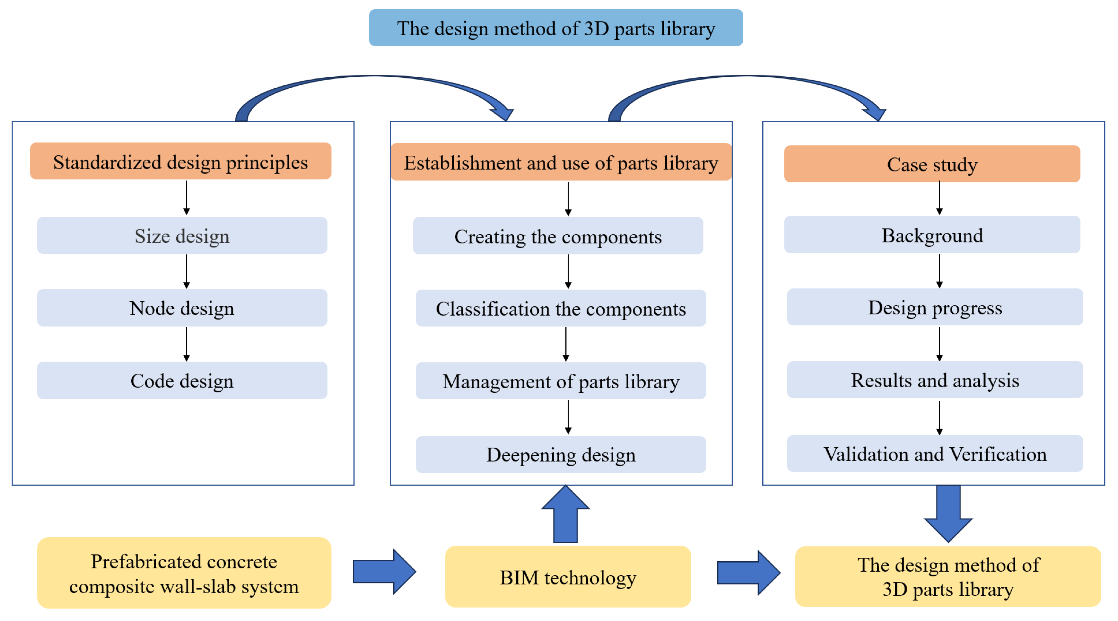
Figure 1 is the technical route of this study.
2. Standardized Design Principles of Parts Library Components
Standardized design runs through the whole life cycle of prefabricated building projects and plays a key role in all aspects of design, production, transportation, and construction. The standardization of the design of prefabricated components is conducive to improving the production efficiency of components, enabling components to achieve unified scale production and improving production quality. Standardized design not only improves production efficiency but also brings significant economic benefits. First, by reducing the diversity of component size and node design, standardization reduces the frequency of mold changes and significantly reduces the cost of mold development and maintenance. Secondly, standardized components can be produced on a large scale, which improves manufacturability and productivity, thereby reducing production costs. Finally, standardized design improves the reuse rate of components, reduces the waste of resources, and improves the sustainability of the project.
ISO 1791 [
32] points out that the core of the modular coordination idea is to simplify architectural design and construction, improve efficiency, and ensure compatibility and interchangeability between different components and modules through the combination of size standardization, tolerance coordination, unified connection mode, manufacturability and flexibility. This standardized method not only improves production efficiency and reduces waste but also provides a sustainable development framework for prefabricated building systems and promotes the process of building industrialization. In order to further manage the components of the parts library, this study encodes the components. Therefore, this study puts forward the corresponding standardized design principles from the aspects of size, node, and coding of the components of the parts library.
2.1. Size Standardization Design
Reasonable component size is the basis for efficient industrial production [
33]. The component is the smallest unit in the design process of a prefabricated structure, and whether its size is reasonable affects many aspects. First of all, the size standardization design can greatly improve the reuse rate of the mold, reduce the operation process of the workers, and reduce the production cost. Secondly, the size standardization design also has an impact on the transportation of components. A reasonable size can reduce the damage of components during transportation and improve the efficiency of transportation. Finally, the scientific and reasonable component size design also directly affects the construction quality and construction efficiency. Through the standardized design of size, the accuracy of component production can be guaranteed, and the qualified rate of component installation and hoisting efficiency during field construction can be improved. Therefore, in the design of component size, the following requirements should be met.
Meet the building’s function and structural safety: Under the premise of meeting the safety of the building, ensure the safety and reliability of the structure under load; large plate design should be adopted to reduce the number of horizontal and vertical joints. According to the above principles and the Technical Standard for Prefabricated Concrete Buildings [
34], the size of the prefabricated component should not be greater than 6000 mm. Combined with the characteristics of the PCCWS, the width of prefabricated wall panels should be controlled between 2000 mm and 5000 mm, and the width of prefabricated floor slabs should be controlled between 2000 mm and 5000 mm.
Meet the requirements of building modulus: Through the size modularization, the combination of components can be better realized, so as to meet different types of bays, reduce the production cost of components, improve production efficiency, and facilitate subsequent maintenance [
35]. This study compares the standards of Chinese GB, American ASTM, and ISO codes [
32,
36,
37]. The results are shown in
Table 2. According to the building modulus coordination standard, the modulus is divided into basic modulus and derived modulus and combined with them to achieve modulus coordination. Among them, the basic modulus is 1 M (100 mm), and the size of all components should be a multiple of the basic modulus; the derived modulus is divided into expanded modulus (2 M, 3 M, 6 M, 9 M …) and divided modulus (M/10, M/5, M/2). The specific modulus sequence is shown in
Table 3.
In addition to meeting the above requirements, the size of the components should also take into account the requirements of production, construction, and transportation [
38,
39]. From the perspective of production and construction, it is necessary to combine the factory’s production equipment, process conditions, construction site lifting equipment, construction technology level, and other factors to ensure the smooth production and installation of the components. The factory’s production equipment specifications, process flow, and worker operation methods all have requirements for the size of the parts. The size of the component should be adapted to the processing range of the production equipment to facilitate efficient production, so as to reduce production costs, improve production efficiency, and achieve mass output. At the same time, it is also necessary to reduce the difficulty of on-site construction and facilitate the assembly and hoisting of prefabricated components. In the transportation link, the size of the component should comprehensively consider the specifications of the transportation vehicle, the load limit, and the transportation conditions of the road to ensure the safety and stability during the transportation process.
2.2. Node-Standardized Design
The joint design of parts library components plays a key role in prefabricated buildings [
40]. It should be clearly stressed, with reliable force transmission, to meet the bearing capacity, ductility, and durability requirements [
41,
42]. Reasonable and effective joint connection can ensure the integrity of the structure and ensure that the load can be effectively transmitted between the components, so that the structure forms an organic whole and, through its own deformation capacity and energy dissipation mechanism, absorb and dissipate seismic energy, improving the ductility and seismic performance of the structure. For the part with waterproof requirements, the joint design and construction quality of the components directly affect whether the structure experiences water seepage, condensation, and other issues, thus affecting the durability of the structure; at the same time, the standardized node design can make the construction process more convenient and efficient. It can reduce the difficulty and workload of on-site construction and improve the efficiency of construction.
The PCCWS is mainly composed of PC slab and PC wallboard, and the components are connected to each other through horizontal and vertical joints [
43]. The connection form is the auxiliary connection between the keyway and the sleeve steel bar. The connection performance of the structural system is good, and the contact area between mortar and concrete is increased by using the form of keyway joint, and the reduction performance of the joint is improved [
44]. At the same time, the connection form of the keyway makes it possible to achieve accurate positioning during the installation of the prefabricated components, which reduces the difficulty of construction and improves the construction efficiency.
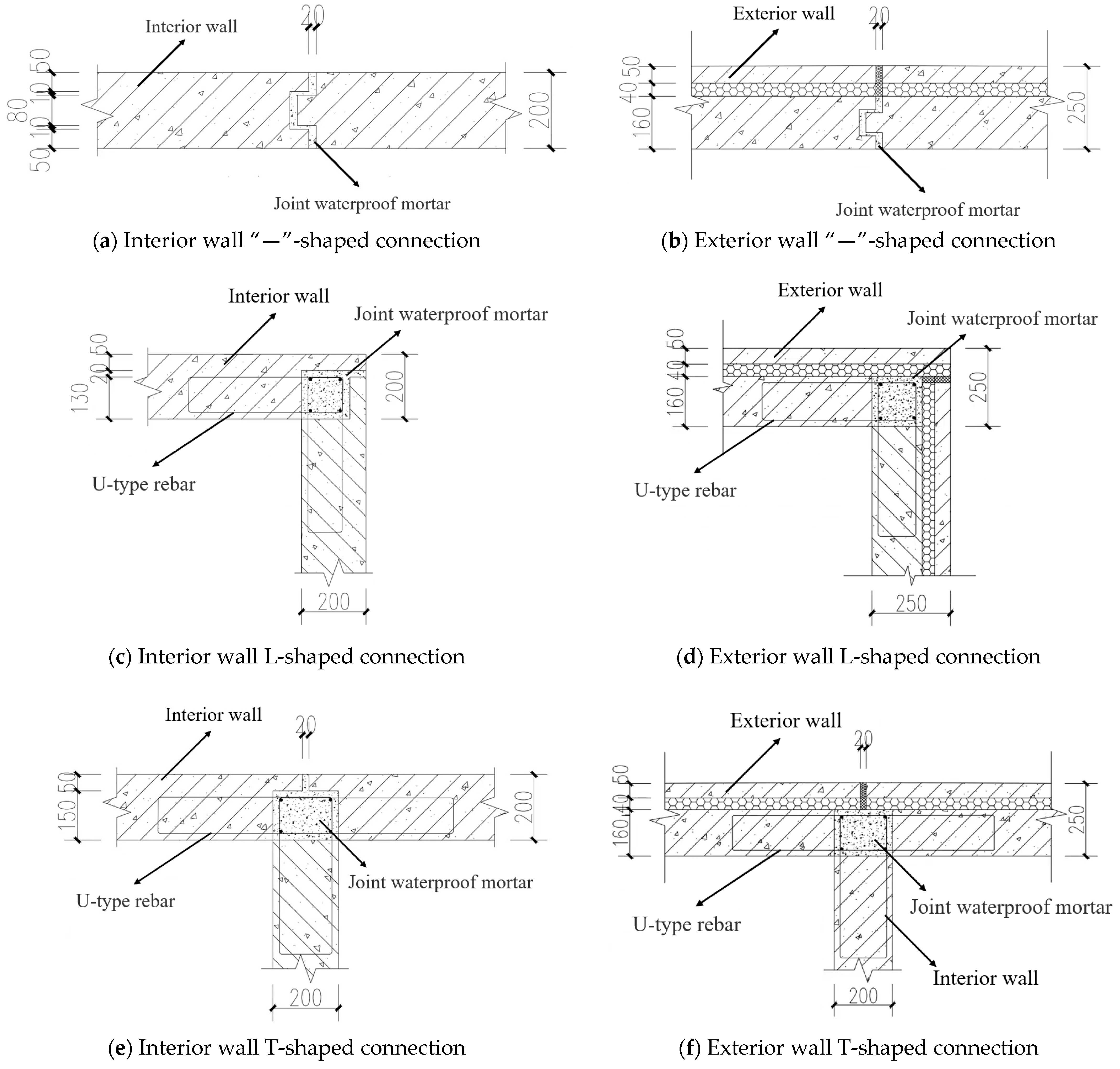
For the node design of the parts library components of the PCCWS, this study is designed according to the following principles. The vertical joints of the assembled composite wall panel system are connected by keyway grouting. According to the different positions and connections of the wall panels, the types of joints are divided into “—”-shaped connection, L-shaped connection, and T-shaped connection. A schematic diagram is shown in
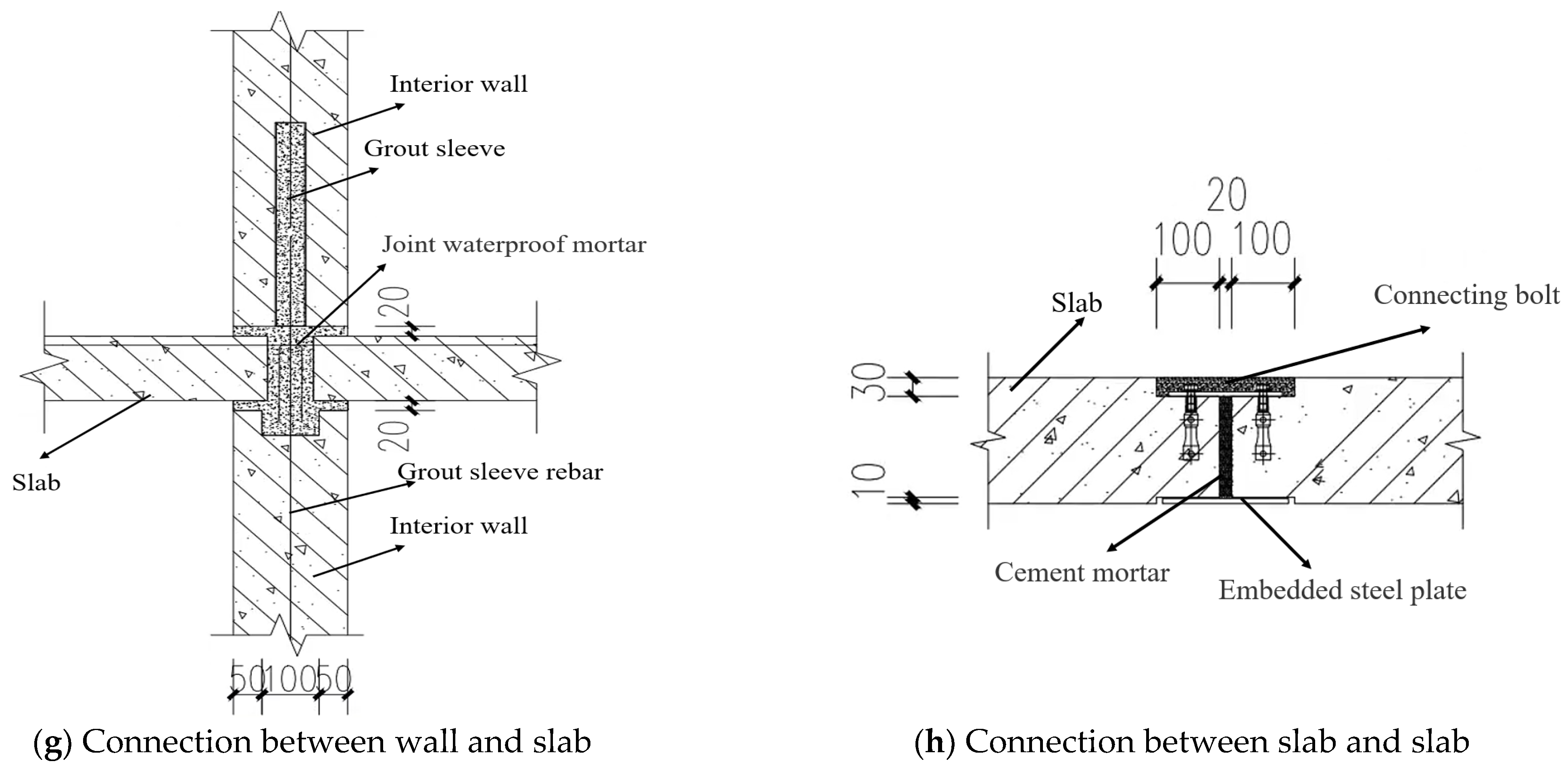
Figure 2a–f. The horizontal joints of the PCCWS are connected by a keyway-grouting sleeve, and the connection form is shown in
Figure 2g. The floor connection of PCCWS can be connected through a close connection, an inclined grouting connection, or an embedded bolt and steel plate connection. A connection diagram is shown in
Figure 2h.
2.3. Coding Standardization Design
In order to facilitate the classification and management of parts library components, it is a very important link to realize the coding standardization of components [
45]. First of all, the standardized coding system can realize the rapid retrieval and accurate identification of component information. Through standardized coding rules, designers can directly obtain key parameters, including project information, component type, such as wall panels, floors, etc., and geometric dimensions (length, width, and thickness), which significantly improves design efficiency. Secondly, coding standardization helps to promote industrial chain coordination. Under the background of industrial construction, the unified coding system eliminates the information barriers between enterprises and regions, so that the design, production, construction, and other participants can cooperate efficiently based on the same set of coding standards. It avoids the obstacle of information transmission caused by inconsistent coding. In addition, coding standardization also provides basic support for the whole life cycle management of the project. From the model creation in the design stage to the progress tracking in the construction stage to the asset management in the operation and maintenance stage, the standardized coding system ensures the continuity and accuracy of information transmission.
When coding components, the following principles should be followed: 1. coding should cover comprehensive information; 2. coding needs to be as simple as possible, easy for users to understand; 3. when encoding, different modules can be separated by “x” or “-“ to distinguish them; 4. coding must be implemented using uniform standards. According to the above principles, this study proposes the basic information code combined with the standard attribute code to encode, where the basic information code corresponds to the external information of the component, and the standard information code corresponds to the component’s own attribute information. The specific coding requirements are shown in
Table 4 and
Table 5.
Among them, “Year code” uses the last two digits of the project year; “Project code” is a letter plus a three-digit number; “Building code” is a three-digit number; “Structural system” is a letter plus a number; “Grantee code” is a letter plus two digits; the “Parts type” is determined according to the type of the component, which is a two-digit letter. For example, the prefabricated inner wall is NQ, and the prefabricated outer wall is WQ. “Floor code” is a two-digit floor number; “Parts code” is a four-digit number; “Plane size” and “Thickness” are six-digit and two-digit numerical sizes, respectively, both in centimeters. After completing the coding of the basic information code and the standard attribute code, the complete component coding information of the part library is obtained by combining them, such as 25A001001C1A01-WQ010001-390×343×20.
3. The Establishment and Use of Parts Library
Based on BIM technology and PCCWS, we use PKPM-BIMBASE 2024 and Revit 2024 software to establish parts library components and use MATLAB 2024 software to establish a 3D parts library. MATLAB was selected primarily for its strengths in mathematical modeling, parametric logic expression, and automated data generation. Its matrix-oriented syntax facilitates the generation of component dimensions, code rules, and cross-variable control logic. Additionally, MATLAB can export structured data in formats easily interpreted by external systems, making it a suitable back-end engine for data preprocessing and parametric rule encoding. This study will take PKPM-BIMBASE software as an example to introduce the establishment and use of a parts library. PKPM-BIMBASE software demonstrates robust capabilities in secondary development, offering comprehensive functionalities and user-friendly operation. The software facilitates parametric modeling of structural components and enables meticulous detailing, allowing for the integration of specialized attributes. Through its open API interfaces, PKPM-BIMBASE provides efficient parametric services, including parameter adjustment, parts library export or import, and automated model generation. Based on the BIM model created by the parts library, PKPM-BIMBASE can realize the deepening design of components. Additionally, the software performs comprehensive 3D model collision detection, evaluating critical aspects such as keyway connection rationality, pipeline system integrity, and electrical circuit continuity. The system also enhances design efficiency by enabling systematic management of component parameter information.
Table 6 shows the strengths and limitations of PKPM-BIMBASE versus other BIM tools (Revit, Tekla). The following further elaborates on the methodological framework for establishing the parts library, detailing its systematic development process and practical implementation strategies.
3.1. System Architecture
The system architecture developed in this study is designed to facilitate standardized modeling, classification, and rule-based management of prefabricated components. First, geometric models of components are created using BIM software such as PKPM-BIMBASE or Revit, allowing intuitive 3D modeling and ensuring compliance with architectural and structural specifications. The geometric and parameter data are then exported and processed in MATLAB, which serves as the backend engine for component encoding, rule definition, and modular coordination verification. MATLAB converts raw geometric inputs into structured component dictionaries, incorporating dimensional standards, production logic, and coding schemes. If necessary, the processed component information can be reintegrated into PKPM-BIMBASE to update geometric parameters or other data. These files are then imported into PKPM-BIMBASE for BIM-based geometric modeling and library construction. Although PKPM-BIMBASE currently supports limited IFC functionality, the component schema is designed to conform to IFC 2x3/4 standards, ensuring future interoperability. The architecture also supports component version tagging, classification indexing, and potential linkage with cloud-based BIM object libraries, laying the foundation for future extensibility and formal version control.
3.2. The Creation of Parts Library Components
This research was conducted based on the PKPM-BIMBASE software platform, utilizing its customized component creation functionality to systematically establish standardized components for the parts library. The operational interface of PKPM-BIMBASE software is presented in
Figure 3. The component creation process is as follows: First of all, the fundamental material properties and component classifications were precisely defined through the “Parameter management” and “Component type” modules. Then, the component dimensions were specified through the “Sketching” and “Stretching” functions. When necessary, the “Rotary” function could be used for rotation to generate column-type components. The “Lending” function allowed components to be extended along required paths, suitable for creating special-shaped components. Finally, the “Merge” and “Cut” functions enabled component combination and trimming, applicable for composite components. In this study, we will take precast concrete composite interior walls, precast concrete composite exterior walls, and precast concrete composite slabs as examples to demonstrate how to create parts library components. The detailed procedures are described below.
Creation of precast concrete composite interior wall:
According to the principle of size standardization, the “Sketching” function is used to specify the plane size of the component, which is 3900 mm × 3430 mm here, as shown in Step 1 in
Figure 4;
Through the “Sketching” function, the plane of the component is selected to create a thickness for the component, which is 200 mm here, as shown in Step 2 in
Figure 4;
According to the standardized design requirements of the node in the PCCWS, first use the “Sketching” function to draw the plane of the node, and then use the “Stretching” function of the software to stretch the plane of the wall panel node, as shown in Step 3 in
Figure 4;
According to the functional requirements, first use the “Sketching” function to draw the plane position of the door opening, and then use the “Stretching” function to create the door opening on the component, as shown in Step 4 in
Figure 4;
According to the coding principle, the standard information code of the parts library component is coded accordingly. Based on the above attributes, the code of this component is NQ (parts type), 01 (floor code), 0001 (parts code), 390343 (plane size), 20 (thickness), as shown in Step 5 in
Figure 4;
According to the structural requirements and the need for preliminary design of the component, observe Step 6 in
Figure 4.
Upon completion of the parts library components creation process, the standardized components can be systematically exported and subsequently uploaded to the centralized 3D parts library database to facilitate efficient component management and utilization in future projects.
3.3. The Classification of Parts Library Components
There are various types of prefabricated components. In order to achieve efficient management and optimize the user experience, a scientific component classification system must be established [
46,
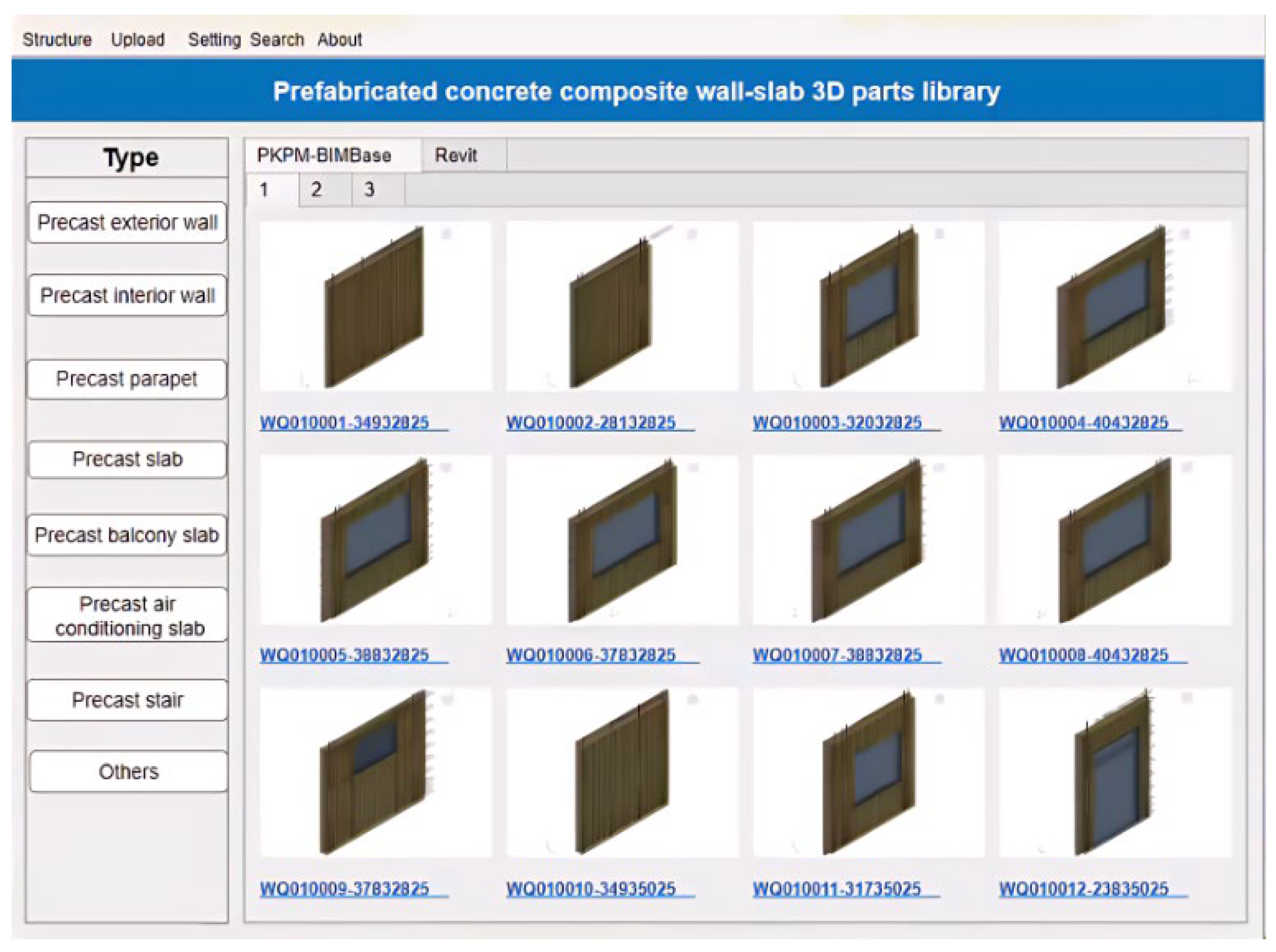
47]. Based on the characteristics of the PCCWS, this study systematically divides the main component types, including precast concrete composite exterior wall, precast concrete composite interior wall, precast concrete composite slab, etc., and establishes a complete parts library classification system, as shown in
Figure 5.
3.4. Management of Parts Library
When the components are uploaded to the parts library, it is necessary to review, manage, and effectively arrange the components to ensure that the parts library can effectively store and call the components to improve the convenience of the parts library. The process is shown in
Figure 6.
First of all, in the process of component storage, the components need to be strictly reviewed. The standard degree of components and the correctness of their parameters are the key elements to ensure that the components can participate in the design normally and the parts library can operate efficiently. Therefore, a storage review of components is the basic requirement for the realization of parts library management. In this process, managers need to review the size of components, node construction, and coding standards. If the component passes the review, it can be successfully entered into the parts library; on the contrary, if there is a problem with the component information, the administrator needs to withdraw the component from the user and propose changes. The specific flow chart of component storage is shown in
Figure 6.
Following successful component auditing and storage within the parts library system, users can proceed to retrieve and call these components. The retrieval and call function of the parts library is one of the important standards to reflect its practicality and efficiency. The specific process is shown in
Figure 6. After registration, users log into the parts library system and select the retrieval methods of components in the initial interface, which are “Keyword search”, “Category Search”, and “Parametric search”, three retrieval methods. “Keyword search” is to retrieve components through the coding of components, which is generally suitable for finding components of specific size types; “Category Search” is to retrieve the category of components, which is generally applicable to find a certain type of components, such as wall panels, floor components, etc. “Parametric search” is to search through component parameters, which is generally suitable for finding components with specific parameters. After retrieving the component, the user checks whether there is a required component in the parts library according to the retrieval results of the parts library components. If there is a required component, the user chooses to call this component; if there is no required component, go back to the previous step and re-retrieve. After the retrieval is completed, the method of calling the component is selected, which is a direct call or an information call, respectively. Direct call is used to export the whole component and upload it directly to the user’s local file; the information call is used to generate the parametric information of the components for the user to view the specific information of the parts library.
3.5. Deepening Design of Parts Library Components
By calling the parts library components and exporting them to the local, PKPM-BIMBASE software can be used to arrange the parts library components and establish the corresponding BIM model. Based on the BIM model, the software can be used to deepen the design of the parts library components and design the reinforcement and pre-embedding of the components; at the same time, the model can also be checked to ensure the correct arrangement of node connections and pipeline systems. Finally, construction drawings of the components can be generated by the software to complete the entire design process.
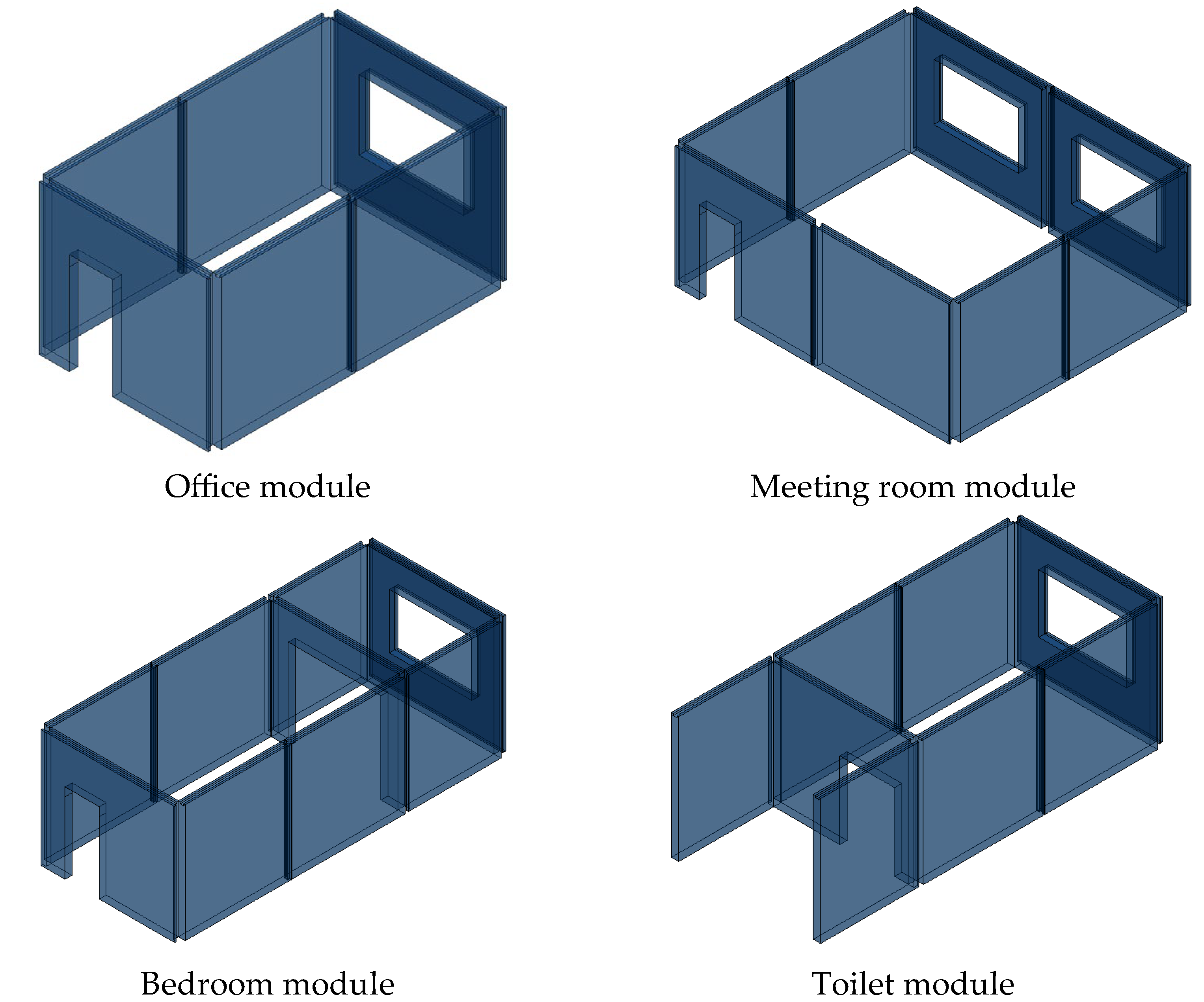
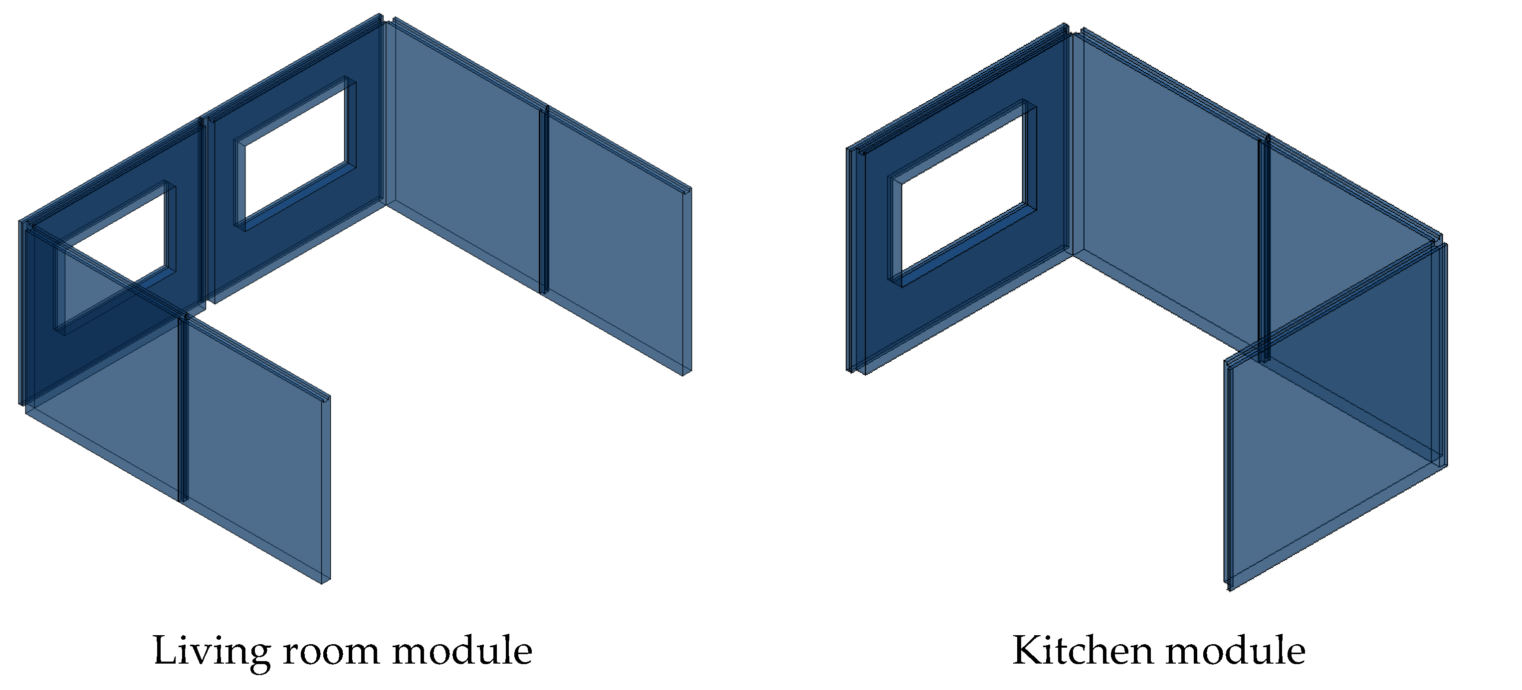
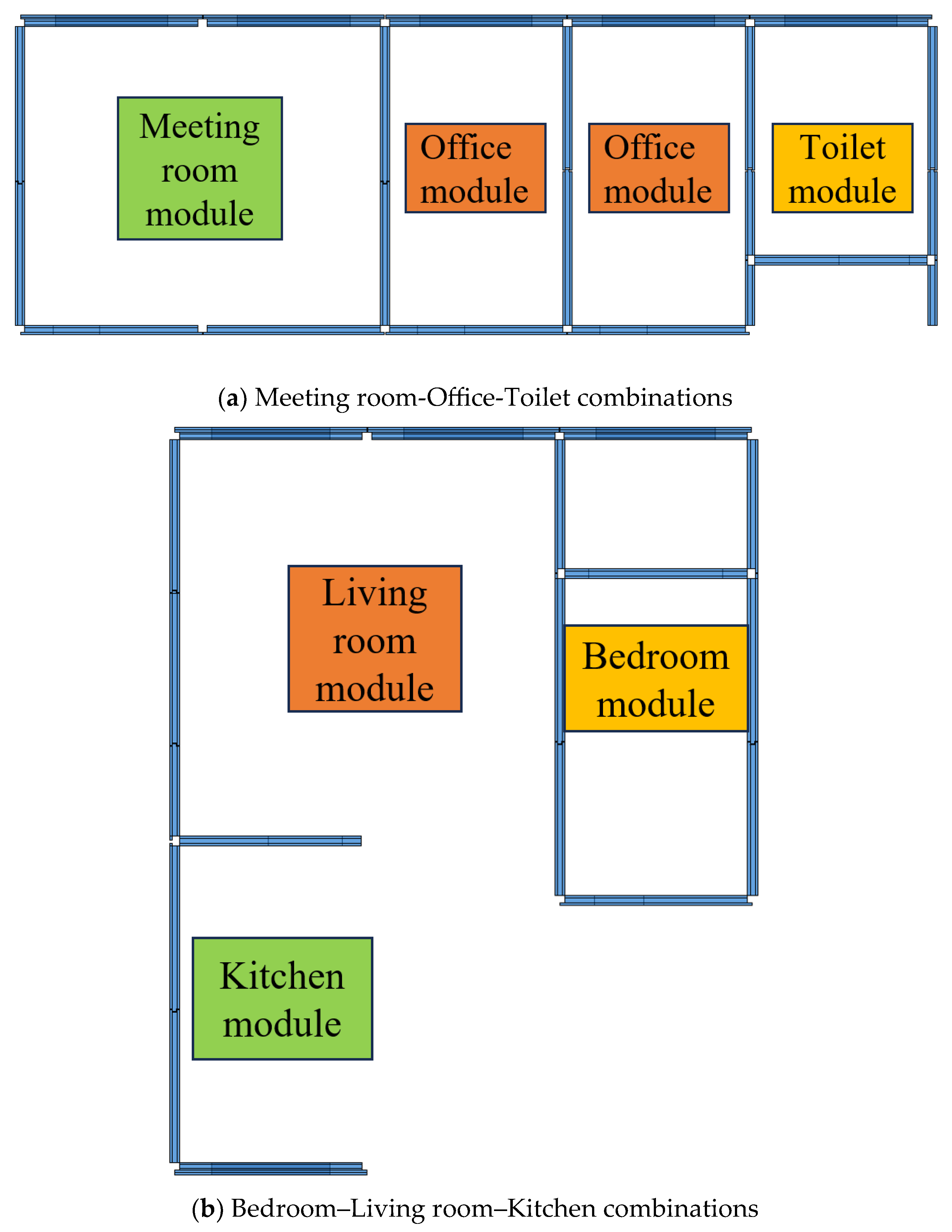
First, the design process begins with component arrangement. Based on the PCCWS, the nodes of the components are standard and unified. Through the unified connection mode and modulus coordination, the system enables all kinds of wall components to be freely combined and spliced, so the parts library components can achieve diversified and flexible combinations. As shown in
Figure 7 and
Figure 8, the user can first select the corresponding standardized components to form modules according to specific engineering requirements. According to the module, it is combined into a complete structure. This design idea of “component-module-whole” not only ensures the degree of standardization but also meets the diversified needs, which provides a new idea for the design innovation of prefabricated buildings.
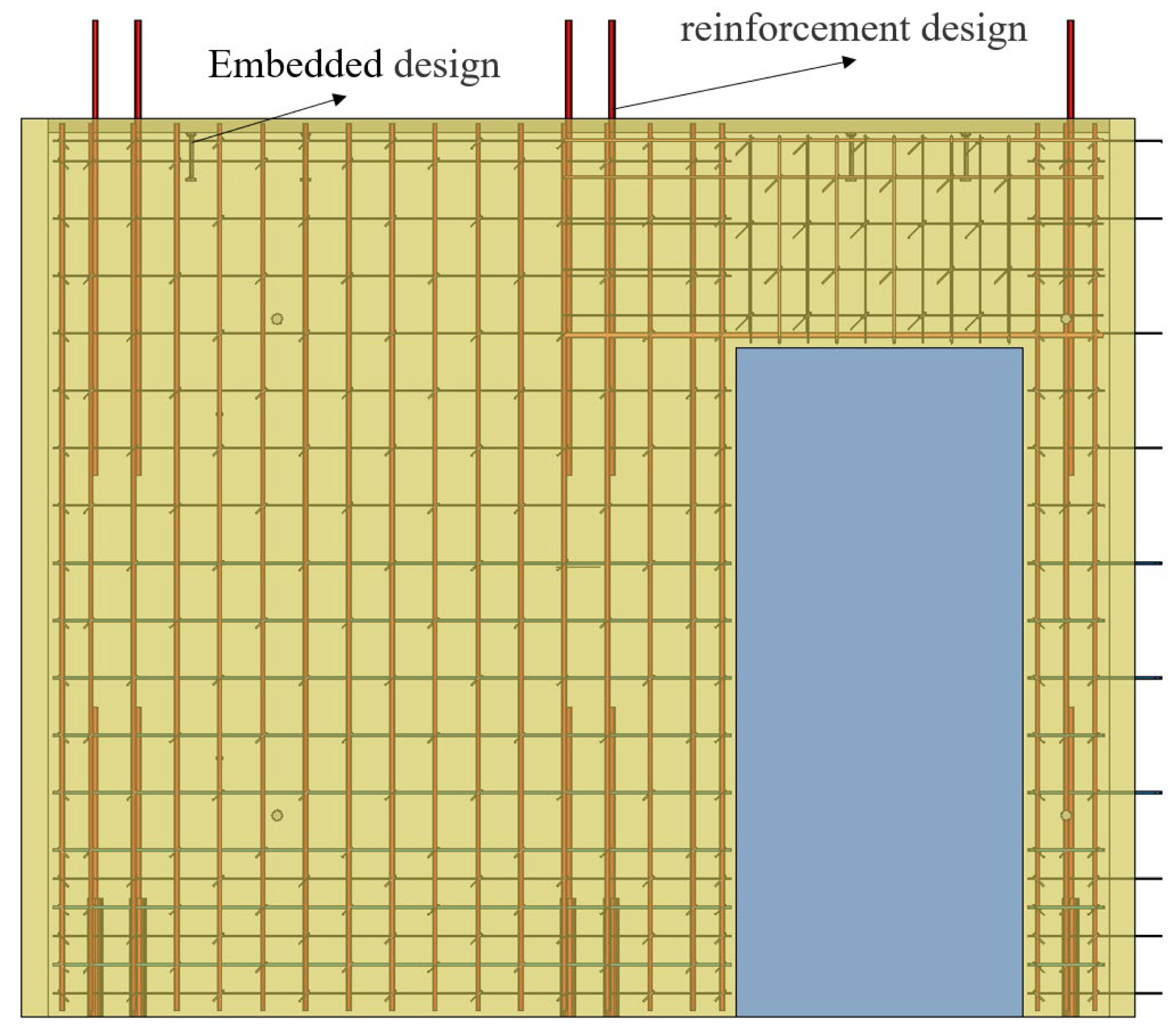
After completing the arrangement of the structure, the component parameters can be specified through the deepening design function of the PKPM-BIMBASE software. Through the “Reinforcement Design” function, the component can be reinforced; through the “Embedded Parts” function, embedded parts can be arranged on the components. In this way, the deepening design of the components is completed, as shown in
Figure 9. Finally, through the “Reinforcement Design” function, the construction drawing of the component can be quickly output, which greatly improves the efficiency of the design and reduces the workload and potential errors of manual drawing. In addition, the software can automatically generate a material list and process data, which is convenient for seamless connection with production and construction.
4. Case Study of Parts Library
This study takes an employee dormitory building as an example to elaborate on the application of parts library. Dormitory buildings, characterized by standardized spatial dimensions, highly repetitive functional units, and regular structural layouts, exhibit excellent compatibility with prefabricated construction systems.
Figure 10 shows the process diagram of the entire workflow.
4.1. Case Background
This project is located in Changsha City, Hunan Province. The project is a three-story dormitory building. Among them, the first floor is 3.6 m high, and the other floors are 3.3 m high. A prefabricated concrete structure is adopted. The project adopts a PCCWS, and the components used include prefabricated concrete composite exterior walls, prefabricated concrete composite interior walls, prefabricated concrete composite slab, prefabricated stairs, and prefabricated balcony panels. The design is carried out by using a 3D parts library combined with BIM software.
4.2. Design Process
(1) Module design
First of all, according to the standardized design principles and the specific requirements of the project, a modular design of the wall is conducted. Taking into account the architectural modulus coordination and node design principles, the components in the 3D parts library are retrieved. Qualified components are searched for and downloaded locally within the 3D parts library; then, the downloaded components are exported in batches and uploaded to the BIM software; finally, the layout of the components is carried out using BIM software.
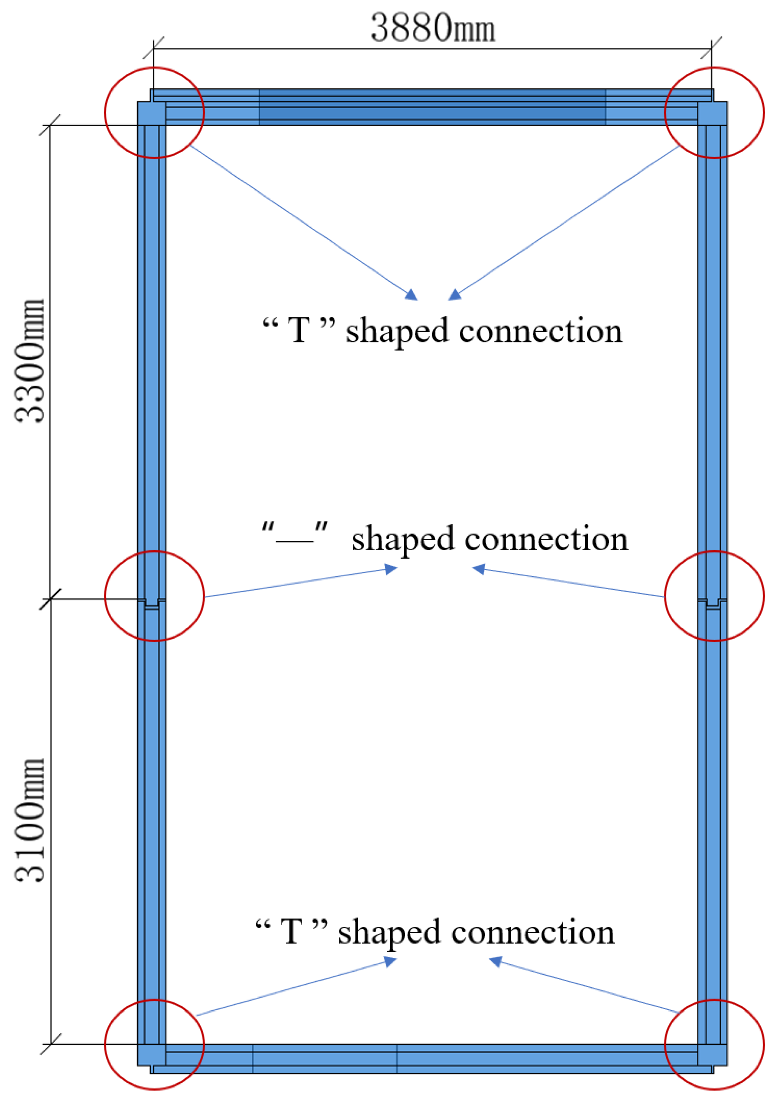
Next, the module design can be carried out according to the existing parts library components. Along the direction of the transverse wall, the wallboard is connected by “—”-shaped connections, and the length of the calling component is 3300 mm and 3100 mm, respectively. Along the direction of the longitudinal wall, the wallboard is connected in a “T”-shaped connection, and the length of the calling component is 3880 mm. The length of the calling component conforms to the principle of size standardization design. As shown in
Figure 11, the corresponding functional modules are established. The remaining modules are designed according to this principle.
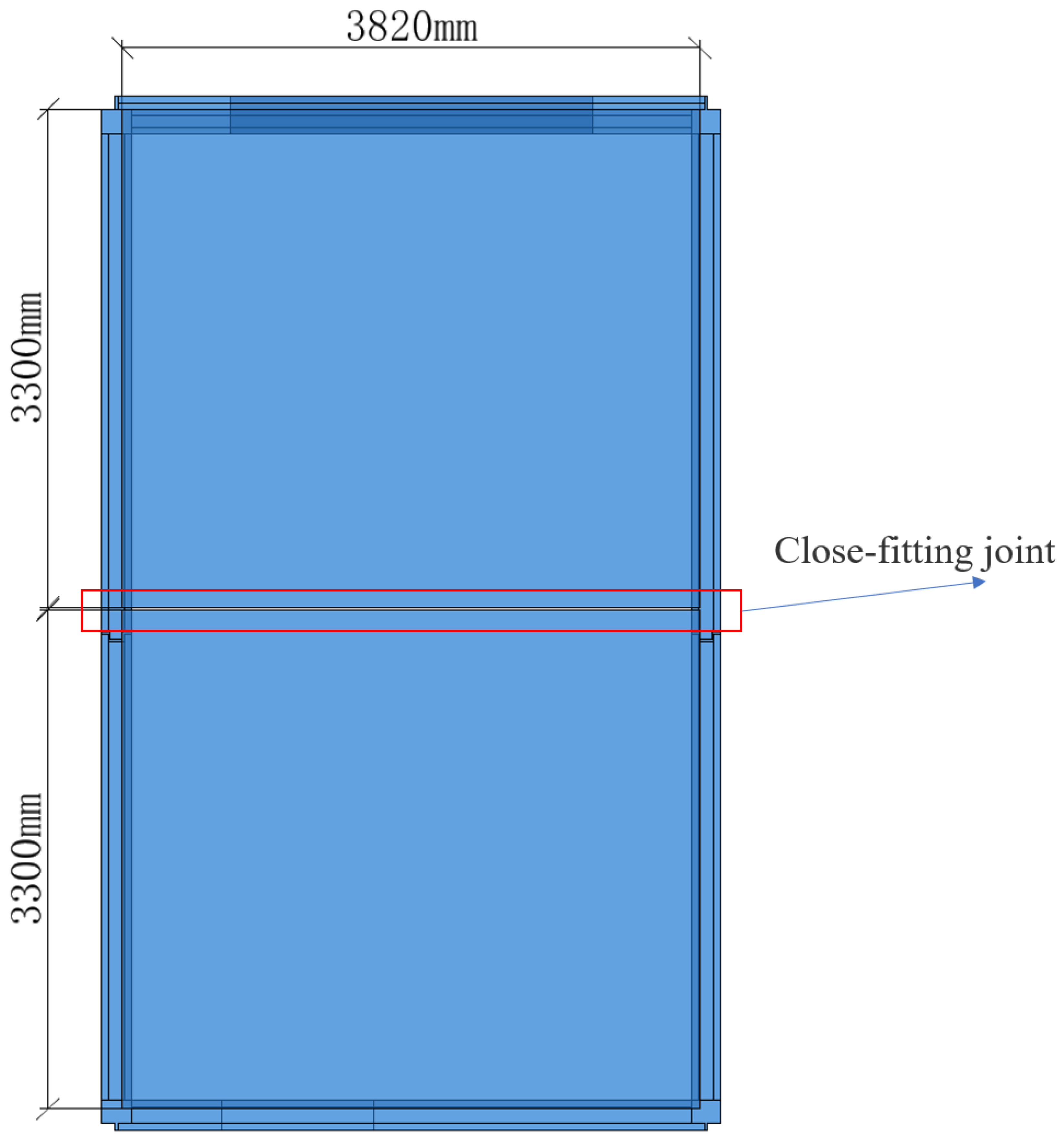
Then, according to the principle of standardized design, the floor of the existing module is designed. Considering the coordination of building modulus and the principle of node design, the floor slab is arranged in the way shown in
Figure 12, and the close connection is adopted. The length of the floor is 3820 mm, the width is 3300 mm, and the size is in accordance with the principle of size standardization design. The rest of the space is arranged according to this principle.
(2) Component layout
After completing the module design, the modules of the unit can be combined to form a whole. According to the design requirements and the needs of users, the modules can be flexibly combined to complete the preliminary design. Subsequently, the module can be adjusted and changed according to the change in demand. At the same time, modules can also be added to the model to meet the needs of users.
(3) Component coding
After completing the arrangement of the components, it is necessary to complete the coding of the components. Since the components already have the standard attribute code in the parts library, it is only necessary to complete the coding of the basic information code of the components according to the project information and then complete the full coding of the components. For the same project, the basic information code is consistent. Therefore, the coding of the components only needs to add the basic information code on the original basis to complete the standardized coding of the component. The basic information code of this project is 25 (year code), A003 (project code), 002 (building code), C1 (structure system), A01 (grantee code). Therefore, the component code is 25A003002C1101 with standard information code.
(4) Deepening design
In the deepening design stage of the project, it is necessary to systematically deepen the design of prefabricated components based on the analysis results of the previous structural calculation and the comprehensive consideration of the functional requirements of the building. The whole deepening design process strictly follows the standardized process described above. Through the digital design platform, the whole process of collaborative design of reinforcement design, embedded design, and construction design is realized.
In the reinforcement design process, the systematic configuration is carried out through the “Reinforcement design” function of the software. The module supports the setting of various parameters of vertical and horizontal distribution of steel bars, including the thickness of the protective layer, the diameter of the steel bar, and the spacing. At the same time, the type specification, arrangement spacing, and other parameters of the sleeve connection steel bar can be standardized. Visual configuration can also be realized for the diameter selection and arrangement of stirrups. For the outer leaf plate of the outer wall, it can also be reinforced by software as needed. When the arrangement of steel bars in specific parts needs to be finely adjusted, the “deepening editing” function can be used to enter the steel bar editing environment of the component, to realize the manual modification of the specific steel bar parameters and ensure that the reinforcement scheme not only meets the structural stress requirements but also conforms to the construction feasibility principle.
In the embedded design part, the systematic arrangement is realized through the “Embedded parts” function module. The module integrates the standardized library of various types of embedded parts, such as demolding embedded parts required in the component production stage, hoisting embedded parts in the construction and installation stage, and temporary support embedded parts. At the same time, in order to meet the needs of the construction equipment profession, the module also provides professional design tools for pipeline pre-embedding and hole reservation to ensure the precise positioning and coordinated arrangement of various professional pipeline systems in prefabricated components.
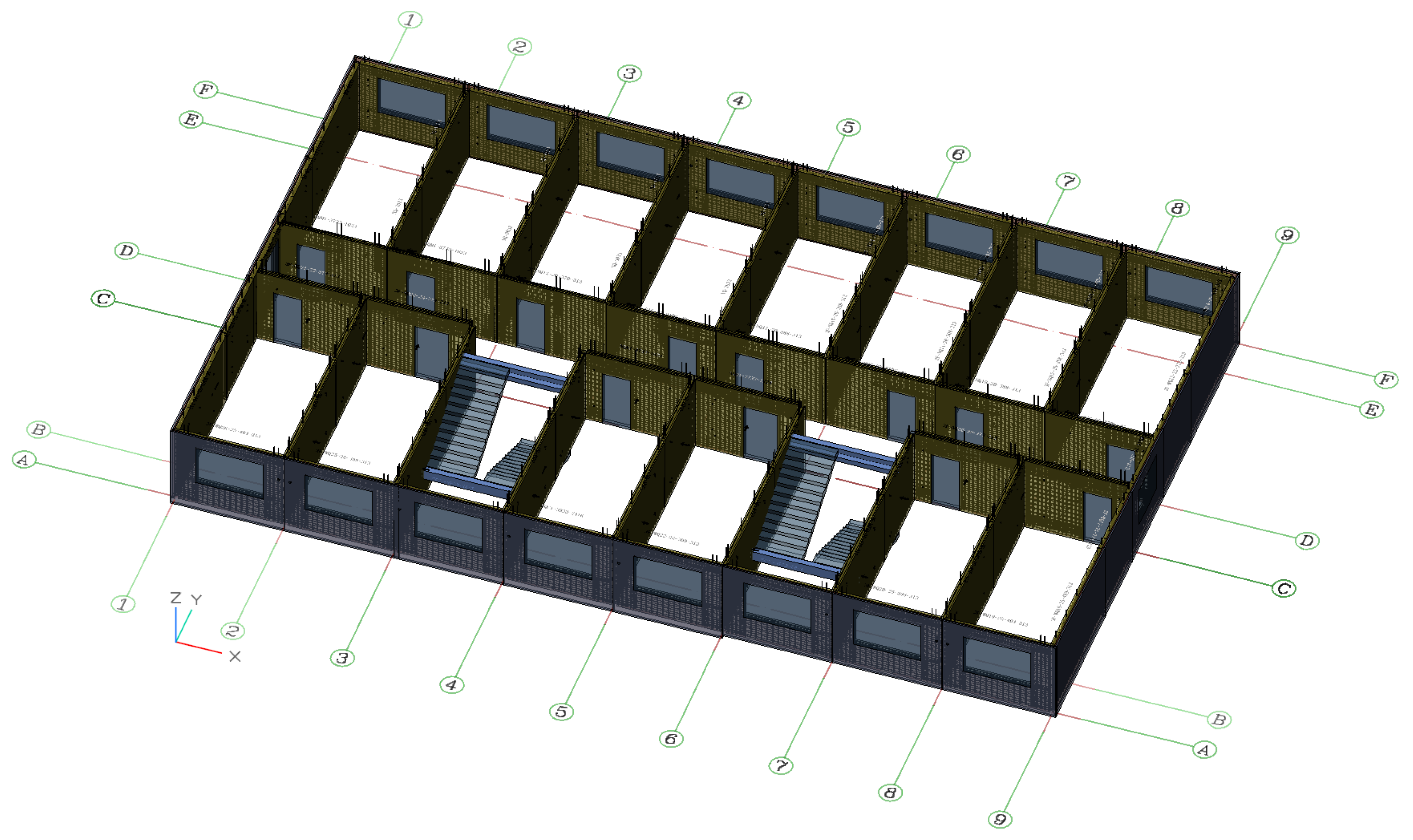
After completing the above design content, the 3D information model based on the PKPM-BIMBASE software platform can review the component nodes and pipeline layout. Through the collision detection function of the model, important indicators such as the rationality of the node connection between the components, the closure of the pipeline system, and the integrity of the electrical circuit can be visually inspected. Finally, the “Detailed drawing” function is used to automatically generate the construction drawing of the component. The final model diagram is shown in
Figure 13.
The organic integration of this series of digital design processes not only improves the design quality but also significantly improves the design efficiency and provides strong technical support for the implementation of prefabricated buildings.
4.3. Results and Analysis
Taking the prefabricated dormitory project as an example, the application of a 3D parts library verifies its practicality and efficiency. Based on the BIM design software, combined with the PCCWS, the design and modeling process of the structure can be quickly completed through the 3D parts library.
Figure 14 shows a comparison of the number of types of standard components and the total number of components.
Table 7 shows the repetition rate of the same components after using the 3D parts library. The repetition rate calculation method of components is as follows: (total number of components-number of component types)/total number of components. At the same time,
Table 8 shows the characteristics and time of the 3D parts library design method based on BIM in the whole design process compared with the traditional prefabricated design method. The traditional design cycle durations were obtained by documenting the average time spent by experienced engineers and designers on similar projects using conventional CAD and manual detailing processes. Each phase—structural design, split design, node detailing, and deepening design—was tracked across multiple past projects, and a time range was derived to account for project complexity and variation in team efficiency. For the BIM-based 3D parts library approach, task durations were measured through practical implementation during the case study. Time was recorded from the initiation of component selection to the completion of construction drawings, using software tools such as Revit, MATLAB, and PKPM-BIMBASE. The reduced time intervals reflect the benefits of automated modeling, parametric detailing, and modular standardization. The reported time ranges capture typical variability under realistic working conditions.
The results show that the application of the design method of the 3D parts library of the PCCWS based on BIM verifies its efficiency and practical value in the design of the prefabricated building. Compared with the traditional design method, the 3D parts library based on BIM significantly optimizes the design process through standardized design and parametric modeling. First, the components’ standardization rate is high. It can be seen from
Table 7 that by using the 3D parts library, the number of types of prefabricated components is greatly reduced, and the repetition rate of similar components is greater than 50%, which greatly improves the repetition rate of the template and reduces the production cost. Secondly, the design efficiency is improved significantly. From
Table 8, it can be seen that the total design cycle is shortened from 504–672 h of the traditional method to 288–480 h, and the efficiency is mostly increased by 42.9%. At the same time, with the increase in project volume, the method is more significant for improvements in design efficiency; finally, the whole process collaborative optimization is realized. Based on BIM technology, the integration of structural design, node layout, and deepening design is realized, which avoids the error of traditional manual drawing and ensures the construction quality.
In summary, the BIM-based 3D parts library provides a replicable and efficient design paradigm for prefabricated buildings through a standardization drive and digital collaboration, especially for modular projects, and provides technical support and practical reference for the industry to promote prefabricated technology.
4.4. Validation and Verification
To evaluate the practical effectiveness of the proposed parts library and parametric design method, a comparative analysis was conducted between manual and automated modeling workflows within the dormitory project. Using a sample set of wall and floor components, it was observed that the average modeling time per component decreased from approximately 20 min using conventional methods to around 11–13 min when employing the automated approach. This represents an estimated time saving of 40–45%. Although these results indicate notable efficiency gains, the analysis is based on a limited number of components and does not include formal statistical verification.
In addition to time reduction, the automated process significantly improved the consistency of component parameters, such as standardized dimensions, coding accuracy, and compatibility with drawing templates. Informal feedback from two practitioners involved in the project suggested that the system effectively reduced repetitive operations, simplified data entry, and facilitated early-stage design standardization. However, limitations were also noted, particularly in handling irregularly shaped components and integrating real-time structural analysis.
Given that this study is based on a single project, this verification remains limited in scope. Future research should expand the system’s application to other building types and introduce more rigorous statistical methods and user evaluations to support broader generalization and refinement.
5. Discussions
5.1. Contributions and Advantages
Based on BIM technology and the standardized design principle of PCCWS, this study presents an integrated 3D parts library system through the components established by BIM software. In actual projects, it enables designers to rapidly retrieve standardized prefabricated components through the 3D parts library, flexibly arrange and adjust the components according to the construction scheme, and finally generate a BIM model that meets the requirements. This design method greatly improves the efficiency of the design. At the same time, through BIM technology, the model can be tested and optimized. In this study, a prefabricated dormitory building is taken as an example, and the 3D parts library is used to design it. The results verify the efficient and practical characteristics of the parts library. The parts library has the following advantages:
First of all, the parts library is accurate and practical. The parts library realizes the digital expression of standardized prefabricated components and fully expresses the characteristics of standard prefabricated components through digital modeling technology, so that all kinds of wall and slab components have complete geometric information and non-geometric properties and can accurately express prefabricated components. At the same time, a large amount of component data is established in the parts library, which can realize the flexible call of various prefabricated components and reduce the time of component design.
Second, the parts library has visibility and convenience. By classifying the components of the parts library and establishing the standard coding system of the components, the efficient retrieval and standardized management of the components are realized. The standardized nodes of the PCCWS are combined with the components of the product library to ensure that the component combination not only meets the structural performance requirements but also increases the convenience of construction.
Third, the parts library improves efficiency and reduces costs. The application of the parts library realizes the rapid call of standardized prefabricated components and improves the efficiency of design. At the same time, based on the principle of standardized design, the application of the parts library improves the reuse rate of prefabricated components, reduces the number of templates during component production, and reduces the design and production costs.
Finally, the parts library is intelligent and collaborative. By integrating BIM technology, the inspection and modification of the model established by the parts library can be realized, and the detailed design can be carried out. At the same time, according to the BIM model, the data exchange of multi-specialty and the whole process can be realized, so as to achieve the whole professional coordination of design–production–construction.
5.2. Limitations and Prospects
This study also has limitations. First of all, this study aims to establish a 3D parts library for prefabricated concrete composite wall-slab components, and other types of prefabricated components have not been developed in depth. At the same time, this study is verified based on only one project, which has limitations. In the future, more types of prefabricated components can be developed and entered into the parts library system, so as to expand the selection range of prefabricated components and provide more comprehensive component data.
Second, the current 3D parts library is mainly based on PKPM-BIMBASE and Revit platform component development, and there may be information loss in data interaction with other mainstream BIM software (Bentley, Tekla, ArchiCAD, CATIA, etc.). Subsequent research can establish a general database in the parts library so that data interaction between the software can be realized.
Third, when designing some complex structures, there are some components that cannot be retrieved in the parts library, which need to be manually created and uploaded to the parts library. At the same time, there is often a conflict between the personalization and standardization of prefabricated buildings. Personalized design will make the structure appear as special-shaped components, which also makes the structure complicated. In the future, the complex and personalized structure can be decomposed into simple and standardized components by supplementing the types of standardized prefabricated components and increasing the layout of the structure, so as to improve the adaptability of standardized prefabricated components to various structures.
Additionally, while the proposed standardized parts library and parametric modeling method resulted in a reported 42.9% improvement in modeling efficiency within the dormitory case study, this result must be interpreted with caution. The efficiency gain was observed in a project with a relatively regular layout and limited component variation. In projects involving irregular geometries, complex customization, or multi-discipline coordination, such gains may not be directly replicable.
From a cost–benefit perspective, although the time savings are significant, the return on investment must consider initial development efforts, software licensing, and user training requirements. For example, the use of MATLAB for parameter logic management requires technical expertise, and the configuration of parametric rules demands manual effort upfront. While long-term benefits such as error reduction, design reuse, and project standardization are evident, their realization depends on the scale and repetition of similar projects.
Finally, due to the different regional and national prefabricated building design specifications and standard systems, it is necessary to adjust the parameters according to different specifications to meet the requirements of different regions when designing the structure. However, the method of a 3D parts library based on BIM proposed in this study is applicable to all regions.
To overcome the above limitations and enhance the system’s scalability, future research should focus on improving the extensibility of component rules, integrating real-time structural analysis, and enabling open data exchange through full IFC compliance. A phased implementation roadmap is also proposed: (1) pilot testing in selected engineering projects, (2) structured training on component logic and library use, and (3) expansion toward an openBIM-compatible framework using API or data exchange plugins. These steps will help transform the current application into a scalable and interoperable platform for industrialized building design.
With the in-depth development of building industrialization and digital technology, the future 3D parts library is expected to focus on intelligent development, break through the existing limitations, and achieve more flexible and efficient design patterns. In the future, research can be carried out in the following directions: (1) Development of IFC-compliant export modules: enable seamless data exchange and improve interoperability with global BIM platforms by supporting IFC standards. (2) Incorporation of AI-based component recommendation: AI technology can be introduced to automate the selection and layout of components based on prior design patterns and project requirements. Through data analysis and pattern recognition of engineering cases, component parameters can be automatically designed, and standard design schemes can be generated to improve design efficiency. (3) Engagement with stakeholders for iterative refinement: collaborating with architects, engineers, manufacturers, and construction teams to co-develop and validate the library in real-world pilot projects.
