Article

Characterization of the Physical, Mechanical, and Thermal Properties of Cement and Compressed Earth Stabilized Blocks, Incorporating Closed-Loop Materials for Use in Hot and Humid Climates

by
Catalina Reyna-Ruiz
1,
José Manuel Gómez-Soberón
2,* and
María Neftalí Rojas-Valencia
3
1
Barcelona School of Architecture, Polytechnic University of Catalonia, 649 Diagonal Av., 08028 Barcelona, Spain
2
Department of Architecture Technology, Barcelona School of Building Construction, Polytechnic University of Catalonia, Av. Doctor Marañón 44-50, 08028 Barcelona, Spain
3
Institute of Engineering, Coordination of Environmental Engineering, National Autonomous University of Mexico, Av. Universidad 3000, Mexico City 04510, Mexico
*
Author to whom correspondence should be addressed.
Buildings 2025, 15(16), 2891; https://doi.org/10.3390/buildings15162891
Submission received: 14 July 2025 / Revised: 2 August 2025 / Accepted: 5 August 2025 / Published: 15 August 2025
(This article belongs to the Section Building Materials, and Repair & Renovation)

Abstract

The United States of America could build 20,000 bases for the Statue of Liberty every year using its construction and demolition waste, and 456 bases using waste glass from jars and bottles. However, some sectors of the population still face a shortage of affordable housing. The challenges of disposing of such large amounts of waste and solving the housing shortage could be addressed together if these materials, considered part of a closed-loop system, were integrated into new building blocks. This research studies compressed earth blocks that incorporate soils and gravels excavated in situ, river sand, crushed concrete from demolition waste, and recycled glass sand. To stabilize the blocks, cement is used at 5, 10, and 15% (by weight). The properties studied include the following: density, apparent porosity, initial water absorption, simple compression, modulus of elasticity, and thermal conductivity. Optical image analysis proved to be a tool for predicting the values of these properties as the stabilizer changed. To assist in decision making regarding the best overall performance of the total 12 mix designs, a ranking system is proposed. The best blocks, which incorporate the otherwise waste materials, exhibited simple compression values up to 7.3 MPa, initial water absorption of 8 g/(cm2 × min0.5) and thermal conductivity of 0.684 W/m·K.

1. Introduction

In the last 40 years, there has been a decrease in the number of new residential constructions available in the United States of America (USA); meanwhile, the population of the country continues to increase.
Despite the fact that the United States is considered a prosperous country—due to its high gross domestic product (GDP)—it currently faces challenges such as housing, which could be solved with approaches similar to those that are already applied in less prosperous countries. These include the use of local materials in housing construction, which, in addition to reducing the necessary energy inputs, minimizes the environmental impact of transport (which is higher when non-local materials are used) [1]. These proposals should address both environmental and social justice aspects.
The earth generated during land clearance or excavation for house foundations is an obvious example of this type of local material, accessible to sectors of the population without access to homes built with “standardized” materials. A documented example of this type of construction with local materials is the case of a school in Gansu province in China, which was built with raw earth at a cost of only USD 82/m2 (2004), representing only 66% of the cost of a school built with concrete block walls and insulating material [2].
There are other alternative secondary materials available for use in sustainable constructions that also provide solutions for sectors of the population with unmet housing needs. For example, in 2018, the U.S. Environmental Protection Agency (EPA) reported that 540 million tons of construction and demolition waste (C&DW) had been generated [3]—values that remain as a reference to this day. Although demolition should be the last option when a building’s sustainable management model comes to an end, when this is unavoidable, other strategies are required for managing and recovering this waste; thus, the recycling of these second-generation materials opens an interesting field of research for possible application. Specifically, in the case of the state of Louisiana, USA (for 2020 and 2021), it was documented that about four million tons of C&DW were deposited in landfills [4]. The report also established that C&DW is a non-hazardous and water-insoluble waste produced during the demolition of structures (including all types of buildings), composed of materials such as concrete, cement, bricks, wood, drywall boards, insulation, etc. Of the above, the present research focuses on the use of crushed concrete residue, which can be used as fine or granular aggregate. These recycled aggregates generally report properties that exceed the minimum acceptable requirements for conventional natural aggregates [5].
Recent studies have explored the use of recycled aggregates, for example, in the formulation of sustainable [6] and permeable concrete [7]. Additionally, ultrafine powders of recycled cementitious materials were activated using heat and incorporated into mortars [8], as well as powdered brick used as a component in low-cost mortars [9]. Particularly in the fabrication of CSEBs, waste concrete powdered [10] contents ranging from 0 to 20% have been studied using cement as stabilizer, achieving compression strengths up to 10.68 MPa and 10.5% water absorption, both of which outperformed CSEBs without the waste concrete powdered at the same concentrations of stabilizer.
Recycled glass sand is another second-generation material, with an estimated 2024 market value (for glass bottles and jars) in the USA of USD 11.61 billion. By 2031 [11] this is expected to have grown by 3.9%. It is estimated that the state of Louisiana (USA) recycles 0.6% of the glass it consumes, considering it to be waste [12], which allows significant opportunities to revalue this material. In the last 65 years, the use of recycled glass as an aggregate, suitable for use as a construction material, has been the subject of several studies [13]. In the case of substitution of natural aggregates by the recycled glass in mortars [14], a 20% increase in the resistance to the expansive action of salt crystallization was observed. Additionally, when replacing 15, 30, 60, and 100% of the normally used aggregates, properties such as density and air content were consistent [15]. When focusing on the drying shrinkage property of mortar with 15% of natural sand replaced by recycled glass sand [16], less shrinkage was observed, although the resistance was lower. Therefore, these units could be used for specific mechanical requirements where the resistance specification can be met. Another use of recycled glass, both as sand and in pulverized form, was in the formulation of ultra-high-performance concrete, outperforming its standard counterpart [17]. One study used recycled glass as a stabilizer by activating it with sodium hydroxide [18] in CSEB, reporting improved performance of the stabilized blocks.
The construction of earth mounds, which are considered to be the oldest earthen structures made by humans on the American continent, began at least 11,000 years ago, before humanity faced the challenges of waste generation at the current scale. These constructions are located on the campus of Louisiana State University (Baton Rouge, USA), and consist of two conical earth structures, each 5.5 m high and built by the native peoples of the Pleistocene [19]. Knowing this past allows us to connect today’s society with those that worked and built with their hands (using the earth around them as material). Therefore, if this was possible so many years ago—not only at this site, but at more than 800 similar archaeological sites in the state—it shows the potential and durability of this local material.
The use of compressed earth blocks (CEBs), functional units used to build walls, is one typical method of earthen construction. These blocks are made using machines that compact the earth inside a mold. From 1982 onwards, the New Mexico Building Code identified them as hydraulically pressed units, and in 1980, approximately 15,000 commercial blocks were produced (their production technology was exclusively Latin American) [20]. A new philosophy of integral development had arisen as a result of Latin America’s post-war social and economic conditions. This involved encouraging communities to find their own strategies to solve their housing needs. In this regard, programs developed in Colombia led the Organization of American States (OAS) to establish the Inter-American Housing Center (CINVA) in Bogotá, in 1951–1952 [21]. It was here that the Chilean inventor Raúl Ramírez created the CINVA-RAM machine in 1957 [22], which was ideal for rural communities as it did not require electrical energy for its operation [23].
When additives are used in a constituent formulation to improve the properties of the CEB material matrix, they are considered “stabilized” (CSEB); this is common practice regarding soils. One of the pioneering studies into the use of additives dates back to 1969, in which CSEBs were manufactured using different concentrations of asphalt and cement [24]. The list of possible materials that have been studied as CEB stabilizers is growing and varied, with cement and lime at the top of the list, followed by natural and synthetic fibers, synthetic polymers, and biopolymers, in studies that have been carried out by several researchers [25]. For example, in a previous work [26], which mentions 57 reviewed studies that used cement as a stabilizer, and which showed favorable results, one stands out. It consistently reported improvements in compressive strength (increases of between 95 and 640%) and in water absorption by capillarity (reduction of between 2 and 29%) when the cement content varied in the range of 5 to 10% and the clay from 9 to 40% [27].
Therefore, the present research aims to study different formulations of CSEB, using cement as a stabilizing additive. Local materials such as earth and closed-loop aggregates (recycled glass sand and crushed concrete from demolished structures) are incorporated using a semi-automatic machine in situ, to contribute to the list of possible sustainable solutions that will permit the construction of solidary housing in hot and humid climates. The strategy of this work, manufacturing, curing, and performing part of the testing in the field, advances the current knowledge in sustainable masonry by helping to bridge the technological gap between high-tech laboratories and the typical conditions of community-oriented efforts. To further facilitate the technology transfer, it is also proposed to use optic image analysis (OIA) coupled with mathematical modeling of the image processing and its correlation to the properties of the CSEB to predict the impact of the stabilizer on each of the properties.
However, the use of cement as stabilizer will reduce the sustainability of the CEB for hot and humid climates. Stabilization is necessary in order to comply with the Louisiana state building code, and so the hypothesis of this work aims to prove that the use of this stabilizer will allow the CSEB to meet the mechanical properties of the applicable regulations and, due to its thermal properties, will provide a construction material that will require less energy consumption throughout the building’s lifetime.

2. Materials and Methods

2.1. Materials

The following aggregates were obtained from local suppliers in Covington, Madisonville, and Mandeville, LA, USA; each material used in this research comes from the same batch, and to ensure the suitability of the particle sizes for use in CSEB matrices, they were screened with a 6.35 mm metal sieve.
  • Stiff clay soil (SCS) and spill way dirt (SWD), clayey local soils purchased clean of wood sticks and big rocks.
  • Mississippi river sand (MRS).
  • Recycled glass (R-G) sand, produced by crushing bottles and jars of a variety of colors.
  • C&DW, produced from demolished structures, construction waste, and other sources of crushed concrete (CDW).
  • Pea gravel (PG), naturally weathered rocks with predominantly smooth and round forms.
  • Limestone (LS) #8, a sedimentary rock with a laminar appearance.
  • Portland Cement (PCs) Type I/II No, 1124 manufactured by Quikrete ® Atlanta, GA, USA, which complies with ASTM C150 [28].
Figure 1 shows the aggregates and the PCs.

2.2. Characterization of Aggregates

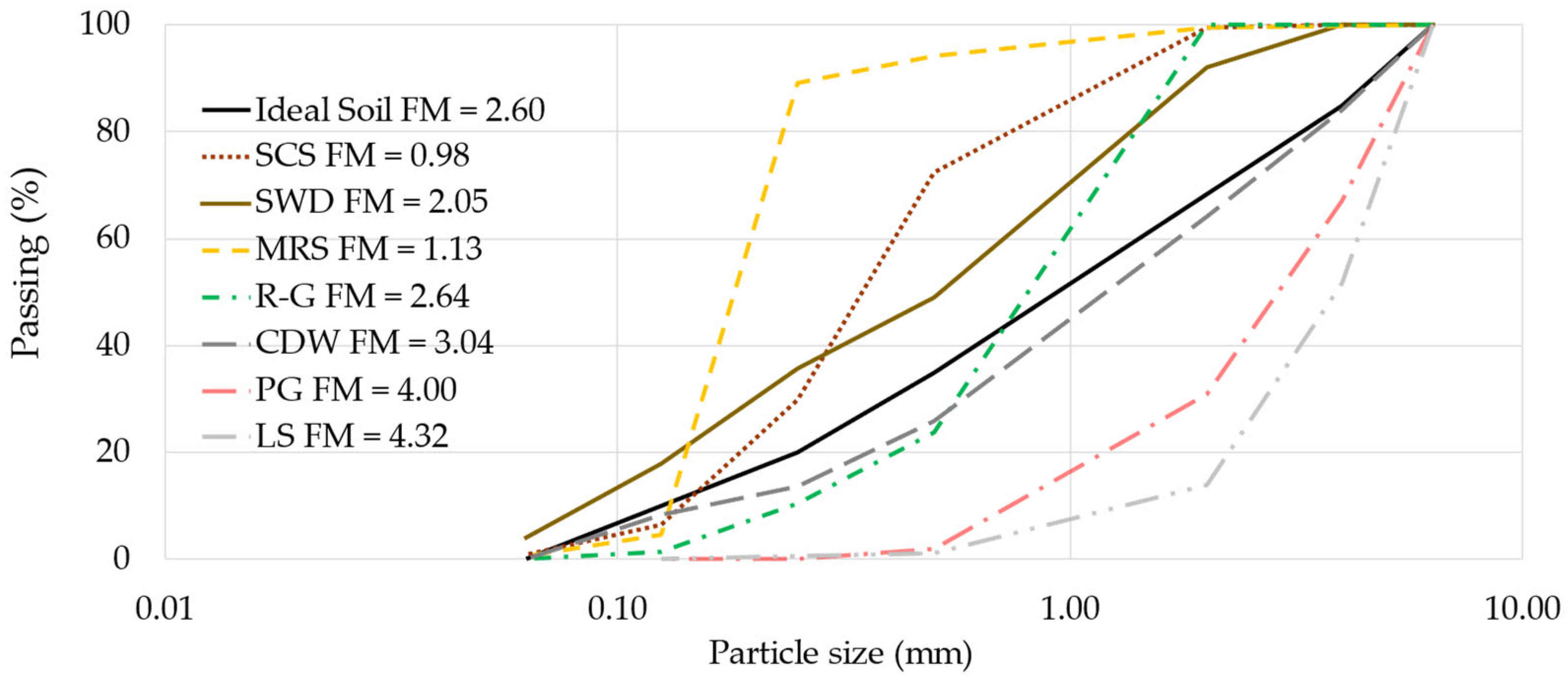
The particle size distribution (PSD) was determined according to the ISO 2591 protocol [29], using sieve numbers 5 (44 mm), 10 (2 mm), 35 (0.5 mm), 60 (0.25 mm), 120 (0.125 mm), and 230 (0.063 mm). Depending on the soil types, the ideal PSD varies according to the stabilizer used in the production of CSEB. In the case of cement use, it has been established as 20% clays, 15% silts, 50% sands, and 15% gravels [30]; this was considered to be the “ideal soil”. To compare the PSD resulting from the analysis of each aggregate with the “ideal soil”, it was assumed that the percentage of the fractions was the percentage of retained mass of each size of the plotted sieve. Figure 2 shows the PSD and fineness modulus (FM) calculated for the sieve sizes used.
Figure 2 above shows that the individual granulometries of the aggregates do not correspond to that of the “ideal soil”; therefore, in each formulation of the CSEBs studied, a combination of different aggregates was chosen to obtain compensated profiles better adjusted to the composite soil, and, thus, make its PSD similar to that of the “ideal soil”.
The aggregates that contributed clay and silt, SCS, and SWD, have been determined in previous research [25] and are now used here. The results are shown in Table 1.

2.3. Formulation of the CSEBs

Four different study matrices were prescribed. The first matrix was established as a reference or base, as it incorporates the natural aggregates (B). The second study matrix replaced natural sand with recycled glass sand (R-G). In the third matrix, the natural sand and both types of stone were replaced by CDW. The fourth matrix incorporated both the recycled glass sand (keeping the stone) and the construction demolition waste (R-GCDW). Three concentrations of stabilizer were proposed: 5, 10, and 15%, for each matrix. The highest concentration was selected to be at the maximum limit of two different norms for CSEB, which established that the maximum content of all the stabilizers combined (including cement) should not exceed 15% in weight [31,32]. The cement content was scaled down to 10% to align with research on CSEB, which has documented that 10% stabilization with cement had compressive strength of 4.83 MPa, representing an improvement of 7% in comparison with a blend of 5% cement and 5% lime [33]. Other studies have used 6 and 8% cement to study the addition of fibers [34], as well as mixtures of 4, 8, and 12% [34]; 5, 7, and 9% [35]; and 6 and 12% [36]. Finally, a study that predicted physical–mechanical properties of hollow interlocking CSEB used 4, 6, 8, and 10% cement [37], therefore establishing 5% as the lowest value for this research. This represented an average of the lower concentrations used by similar studies and also provided a concentration that will serve as a benchmark for three equal intervals of cement concentration.
Table 2 shows the compositions of the four matrices with their three stabilizer variants; the order in which the different materials are presented follows the order used in the mixing (as indicated).
The in situ fabrication strategy used for this work involved using the materials with the moisture they contained at the moment of fabrication, as no prior energy-intensive drying process was implemented. Samples were taken of the materials and their moisture content was established. A preliminary calculation of the mixture’s moisture was determined, as well as the amount of water to be added during the mixing step to reach 10% [38]. No further additions of water were made during compression. Therefore, rather than controlling the moisture, it was assessed as accurately as possible. Two samples of the mix per sub-batch were analyzed for total moisture content as each batch was placed in the hopper. The average moisture of the eight samples (per each mix) was used as the total moisture of the mixture, and, using this information, the percentage of each component was adjusted. Table 2 shows the compositions of the four matrices with their three stabilizer variants, producing a total of 12 formulations for this study. The proctor test performed on the soils indicated ideal moistures of 12.05 and 13.2% for SCS and SWD, respectively (see Table 1); however, as the mixtures include other components, these would only provide a generic approach. In this study, the water/cement ratio ranged from 0.6 to 2.8, with an average of 1.4. These values lie within the values of a study that predicted the moisture content of cement CSEB according to the characteristics of the soils they used [39]. These reported 0.5 to 1.7, with an average of 0.90. The values from a study of CSEB stabilized with thermoactivated recycled cement [40] showed 1.45–3.13, with an average of 1.45.
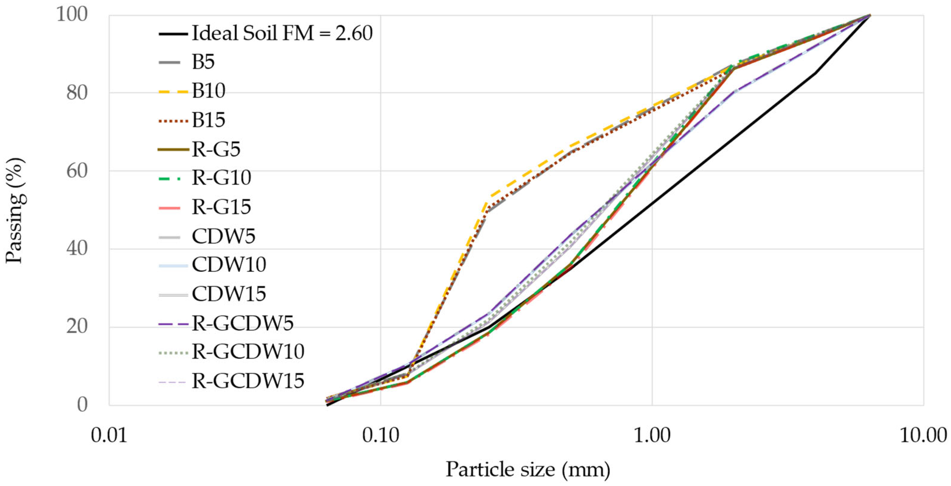
Each aggregate contributes a different fraction, as shown in Table 2, and each fraction brings its own particle distribution, which is illustrated in Figure 2. Knowing these fractions and their respective PSDs, it is possible to estimate the PSD of the composite soils of each study matrix (excluding water and cement) on a dry basis. Figure 3 shows the PSDs of the composite soils.
Figure 3 shows that the PSDs of composite soils are closer to that of the “ideal soil” and, despite some profiles being juxtaposed between the different matrices, they show that the composition of aggregates in their formulation achieves this homogeneity on a dry basis and before the addition of PCs.

2.4. Manufacture of the CSEB

The mixtures were manufactured based on the weights of the aggregates and PCs, all of which were weighed on a Rubbermaid® digital scale (Huntersville, NC, USA). This has a maximum capacity of 68 kg and an accuracy of 0.09 kg, measures 30.5 × 31.8 cm, and has a non-slip weighing surface. All materials were consistently mixed in four sub-batches for each batch of PC content to achieve optimal homogeneity; the mixing was carried out in a Yardmax mixer, model YM0115 (Roselle, IL, USA), which operates at 120 V/60 Hz/500 W, and has a mixing drum with a volumetric capacity of 0.133 m3 and 125 kg.
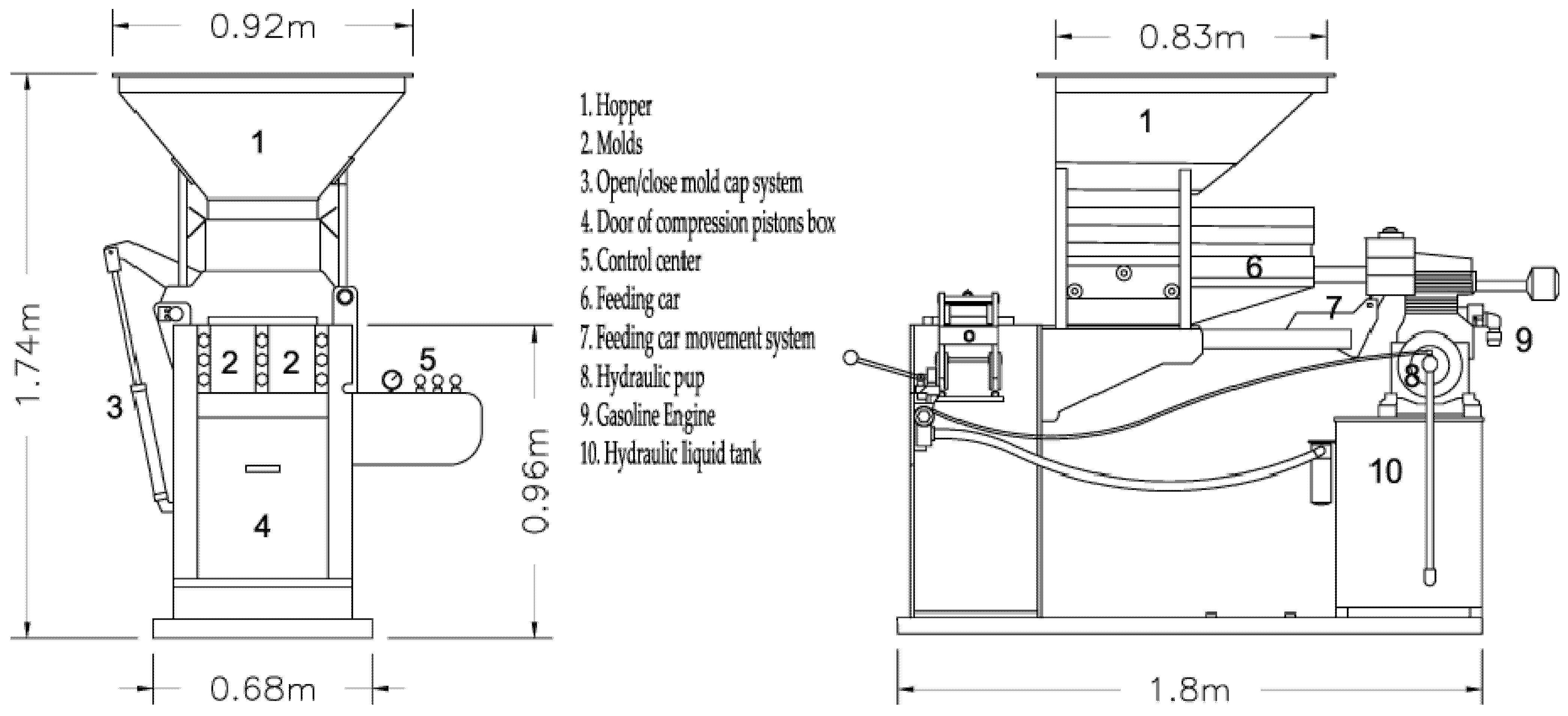
The mortar obtained was placed in the hopper of the CSEB molding machine, which is a Cinva-Ram type machine of the Ital-Mexicana brand, model Adopress 3000, serial number 205199 (Naucalpan de Juárez, State of Mexico, Mexico). The machine is manually operated by unidirectional levers that activate the hydraulic oil driven cylinders for power transmission, which are connected to a gasoline engine. A lever moves a carriage that emerges from the base of the hopper and doses the mortar into two molds, of internal dimensions 30 × 15 × 19.5 cm each. Into each mold, the machine pours 8775 cm3 of the mixture of each formulation (at this point, the reference of the CSEB was called zero time (T0)).
Another lever closes the lid of the molds and the third lever activates the base of each mold, which is raised by applying a constant maximum compaction force of 14.71 MPa for three seconds. The specifications of the Cinva-Ram machines estimate that this compaction in the manufacture of the blocks is capable of reducing their volume by up to 60% [22]. Finally, the compression lever is moved downwards, in the opposite direction to the initial compaction, and the machine is opened. Then, it is raised again, to demold the blocks (this instant in time is called Time 1 (T1)). Figure 4 shows the molding machine used.

2.5. Setting

For each study matrix, between 11 and 14 units of CSEBs were manufactured and dried for 28 to 52 days under the environmental conditions of southern Louisiana, located about 3.45 km north of the shore of Lake Pontchartrain and 2.77 km east of the Tchefuncta River. The local conditions were 10 to 36 °C temperature (average 26 °C) and 21 to 100% relative humidity (RH) (average of 71.43%), with a record of 17 days of rainfall [41]. The CSEB units were always protected from any possible direct action of the sun or rain (this instant of the final curing time of the CSBEs is called Time 2 (T2)). These conditions are consistent with what was reported in other studies, for example, curing for 28 to 45 days at ambient temperatures of 30 ± 5 °C [42]. Meanwhile, the high relative humidity condition of the present study (as cited above) is equivalent to having been cured in polymeric bags to preserve production humidity [43].

2.6. Characterization of the CSEB

Each of the CSEBs manufactured—at times T1 and T2—were weighed on a Suofei SF-802 digital scale (Jiangyin, Jiangsu, China), which had a maximum capacity of 25 kg and an approximation of one gram. They were also measured using a flexible metal tape with an approximation of one millimeter. The geometric density was calculated and the apparent porosity was determined (using alcohol as an immersion liquid) according to the UNE-EN ISO 18754:2022 [44] standard, Methods B and A2, respectively.
A sample size (on average 16% of each matrix’s production) was taken to perform the initial water absorption velocity (AbsCoeff10) (according to the NMX-C-037-ONNCEE-2013 [45]) and simple compression (SCT) (NMX-C-036-ONNCCEE-2013 [46]) tests; two different blocks were used for each test. Several authors have presented proposals for the acceptance plans of quality control sampling when it comes to destructive testing (the case of SCT), with some mentioning that the final number of specimens to be destroyed is a random number [47,48].
In the particular case of SCT, the test was established by means of a field press of our own elaboration, using a frame with a base of 508 × 406 mm and a total height of 800 mm, reinforced with 3.175 mm thick ASTM 36 square steel tubing for the vertical supports and 6.35 mm for the horizontal reinforcements. This frame also contained two fixed steel plates of the same thickness, connected with 15.875 mm hexagonal head screws, and two movable plates between which the specimens were placed. They were subjected to a manual force applied with a BIG RED Model ATH95000iBR hydraulic jack manufactured by Torin, Inc. (Baodin, China), calibrated with a 400,000 lb Tinius-Olsen Universal machine from the University of New Orleans. The above configuration can be considered acceptable, based on other previous studies that focused on the design of hydraulic presses of their own manufacture, which have been used for other determinations [25,49,50,51,52,53]. Figure 5 presents various images and details of the configuration of the field press used.
The longitudinal propagation velocity of an ultrasonic wave was also determined according to the ASTM C597-22 method [54]; for this test, a device from the Pundit Lab/Proceq brand (Schwerzenbach, Switzerland) was used. This method consists of determining the longitudinal pulses of the ultrasonic waves generated with an electro-acoustic transducer, determining the transit time of the pulse electronically; once the length of the specimen is known, the speed of the ultrasonic pulse is determined. This speed is related to the elasticity property of the material, and, using the equation indicated in this standard, the dynamic modulus of elasticity (MoE) is obtained. Figure 6 shows the setup and equipment with which this test is performed in the assay of one of the CSEB samples.
To determine the MoE, the formula cited in the regulation requires the use of the density of the test blocks. The apparent geometric density was used, obtained in accordance with the UNE-EN ISO 18754: 2022 [44], Method B standard. For its determination, it was also necessary to establish the proportionality coefficient of longitudinal and transverse deformation (Poisson). This was established according to the ASTM E494-15 procedure [55] (cited in previous research [56]) for each study matrix, considering the average value of five determinations.
This parameter involves the confluence of various characteristics, thus resulting in a broad view of the CSEBs’ behavior. Finally, it also allows for the complexity of the matrices and the impact of the manufacturing and curing conditions in situ.
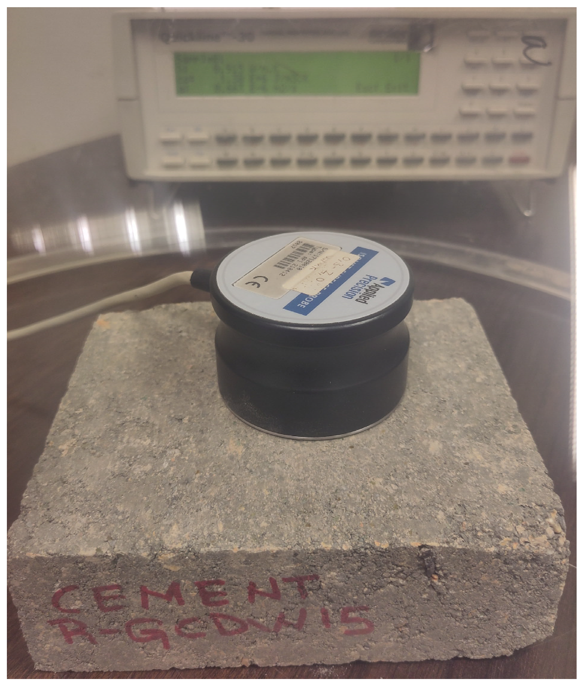
The thermal conductivity (TC) of the CSEBs was also determined, using a multifunctional Quickline-30 Thermal Analyzer (Anter Corporation, Pittsburgh, PA, USA). This method takes between 16 and 20 minutes to achieve steady-state conditions, and has a measurement accuracy of ±10% [57]. This test is a transient heat pulse method that uses a single probe and has been widely used for determining soil TC [58]. Figure 7 shows the equipment used for testing one of the specimens of the CSEBs under study; the configuration consists of an electrode in contact with the specimen (both of which are inside a polypropylene dome to protect the measurement from potential air currents) and the box or screen for reading and determining the test.
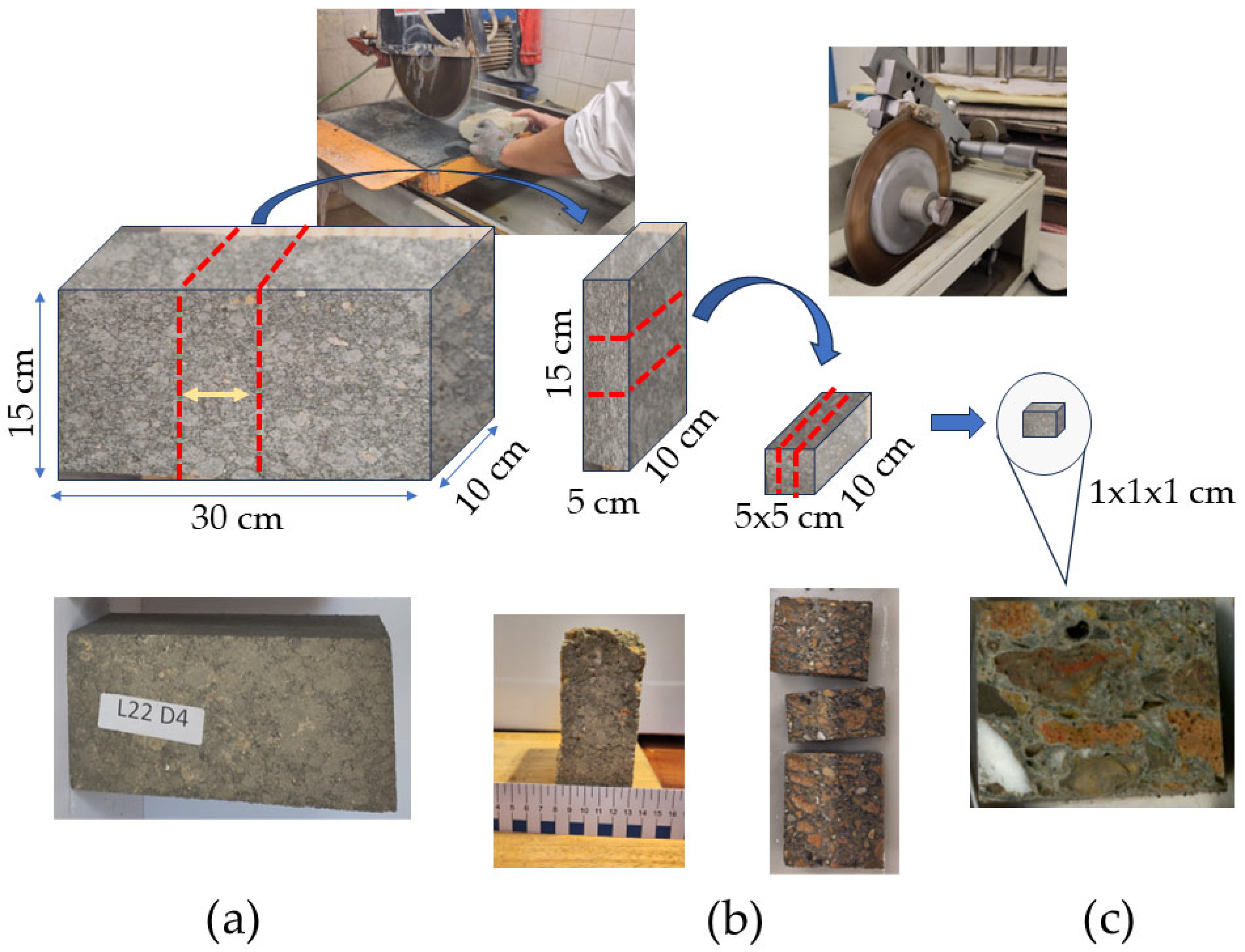
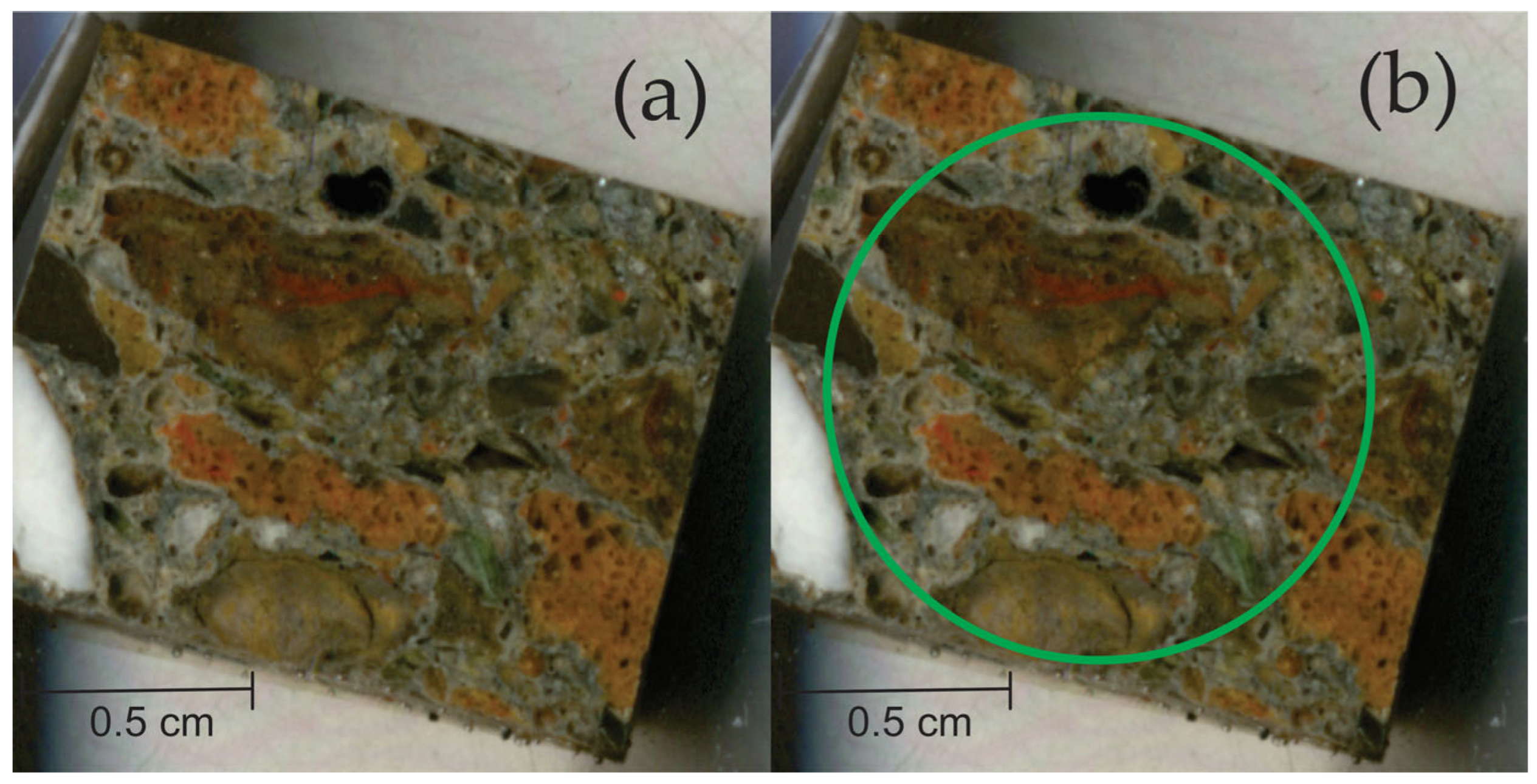
Finally, the microstructural components of the CSEBs were studied, using the OIA technique, for which the Image-Pro v. 11.0.4 Build 9821 software was used. The samples were obtained as follows (see Figure 8), starting with the untested CSEBs of each of the R-GCDW matrices. Cuts were made in their central areas (thus avoiding any possible border effect), seeking to reach the core of each CSEB. The cuts were made using a mechanical table saw with a Durher Model “2800 rpm Miter saw” diamond saw blade (manufactured in Zaragoza, Spain). The last two cuts were made with low-speed Isomet precision equipment (300 rpm) (Buehler, Lake Bluff, IL, USA) with a diamond saw. The final specimen had an approximate size of 1.3 × 1.3 × 0.7 cm.
Once the cut specimens were obtained, they were immersed in inclusion resin and catalyst (EpoFix and EpoFix Hardener). The emptying process in the sample container molds was carried out in a Cast n’ Vac Model 1000 (Buehler, Lake Bluff, IL, USA) vacuum chamber at a pressure of −92 KPa. After the vacuum chamber, the samples were kept under laboratory conditions for 24 h and then at 40 °C for 7 h (complete hardening of the resin). Finally, the samples were subjected to a metallographic polishing on the study side. The following polishing sizes were used: #120, #240, #400, and #800 (Carbi-Met silicon carbide sandpaper), in a semi-automatic Buehler EcoMet (Lake Bluff, IL, USA) polishing machine and using Lapping Oil (Buehler 60-3520-128) as fluidizer. Finally, they were hand- polished with Presi PiC latex-free diamond paste (Eybens, France), with a thickness of one μm. Figure 9 shows an example of the process of obtaining the study samples for the OIA (case of the R-GCDW15 matrix). Images of the processed samples were obtained using a Seiko Epson GT20000/EU-45 scanner (Suwa, Nagano, Japan). For processing the images, the Image-Pro v. 11.0.4 Build 9821 software was used for the OIA.
In cases where statistical data analysis was required, the Statistical Software Package for Social Sciences (SPSS) v. 29.0.0.0 (241) software was used. The Solver version 2025 Q1 software [59] was applied for determining equations by means of progressive numerical regressions.

3. Results and Discussion

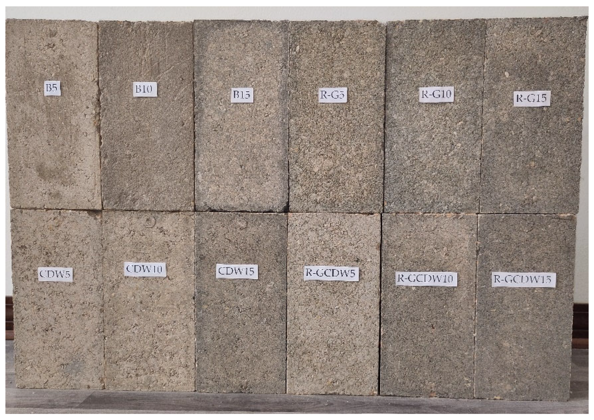
Table 3 presents the average results of each formulation. Figure 10 shows the top face of the compression direction of an instance of each matrix and its batches.

3.1. Density

The density of the CSEBs calculated in T2, in all the study matrices, exceeds the density value of 1750 kg/m3, which is specified as a minimum value in the SLS 1382 [60] standard cited in other works [61,62]. Some studies recommend adjusting the production of CSEB to a density value of 1800 [63], while another study suggests a value of 1830 kg/cm3 [64] (with PCs of 10%). Even values between 1785 and 1986 [65] (with PCs of between 0 and 4% with different types of soils) have been obtained. Figure 11 shows the experimental bulk density values for the study matrices.
From the above, it can be determined that the variation range of the study matrices was established as between 1858 and 1989 kg/m3, a minimum value always higher than the previous studies cited. Regarding the maximum values reached, these were always high when a PC = 15% was used. Figure 11 shows the typical standard error bars ( σ x ).
Therefore, for CDW and R-GCDW matrices, the content of PCs is considered to be the direct cause of the increases or predictable proportional behavior of the density of the matrices. On the other hand, it is also evident that for the B and R-G matrices this variable is not the only one that controls this property, allowing for the possible existence of other external variables not considered in the research.

3.2. Apparent Porosity

Matrix B establishes porosity of −2.06% when PCs changes from 5% to 10% (first differential PCs range (FDr)), and of −1.48% when changing PCs from 10 to 15% (second differential PCs range (SDr)); there is also a reduction in total porosity of −3.54% when going from a PCs of 5 to 15% (total differential PCs range (TDr)). For its part, the CDW matrix establishes an FDr of −3.21%, an SDr of −0.52% and a TDr of −3.74%.
The R-G matrix maintains the same trend, reporting −1.41% in its FDr (with respect to the B and CDW matrices); however, for the SDr the trend reverses to +0.59%. Inverted trends (with reference to R-G) were established for the R-GCDW matrix, which reached a porosity of +2.08% for FDr and −0.94% for SDr.
Figure 12 presents the apparent porosity results for the different study matrices; all the values obtained in this study for the matrices and their different PCs are lower than those reported in previous similar studies [66], in which PCs of 3.7, 5.5, and 7.4% were used, and porosities of 31, 29, and 30% were obtained, respectively.
The numerical fit trends of each matrix group established inverted linear equations for the B and CDW matrices; while for the R-G and R-GCDW matrices they are of the second-order polynomial type (direct for the first and inverse for the second). This could indicate that PC content is directly related to the reduction in porosity in the B and CDW matrices. In the case of the R-G and R-GCDW matrices, the possible existence of variables not included in this research (constant term of the equations for the unknown x2) must be taken into consideration, with the effect of the variables not included in the R-CDW matrix (−0.00605x2) being greater than for the R-G matrix (0.0401x2). Therefore, for B and CDW, this validates the argument of a previous study, which established that one of the contributions to CSEBs containing stabilizers is the generalized reduction in the porosity of their matrix [67]. In particular, due to its hydraulic reaction capacity, PC creates new compounds which bind to the rest of the soil particles, thus achieving a higher density [68].

3.3. AbsCoeff10

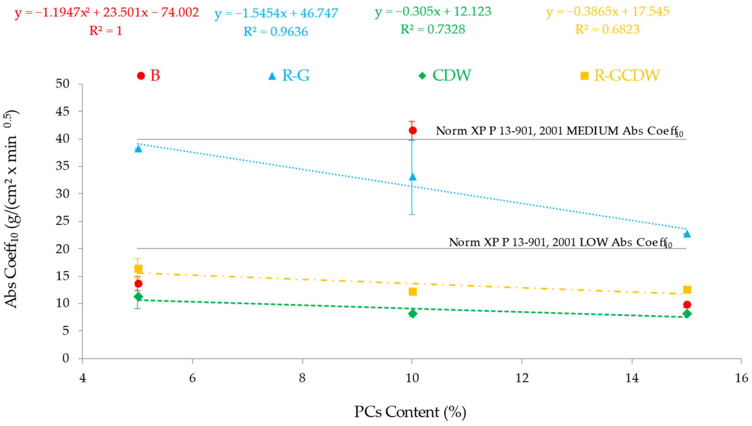
Figure 13 shows the experimental results obtained from this property for all the matrices studied, with the respective typical standard error ( σ x ), as well as compliance with the relevant regulations.
The R-G, CDW, and R-GCDW matrices established inversely proportional trends to the content of PCs, although the decrement effect of AbsCoeff10 is more significant for the R-G matrix than for the others. The FDr represents a change of −5.12 g/(cm2 × min0.5) for R-G compared to an average of −3.67 g/(cm2 × min0.5) for the other two; the SDr represents a change of −10.33 g/(cm2 × min0.5) for R-G compared to an average of +0.211 g/(cm2 × min0.5) for the other two. This is consistent with a previous study that determined, through the total water absorption test of the CSEBs, values for thirteen of their study matrices (joint use of PCs (6, 7, 8, 9, and 10%) and fly ash (FA)), and reductions of −20.05, −9.53, −11.64, and −3.48%, respectively [69]. A previous parallel study [27] established that increases in PCs of 5 to 10% led to reductions in the initial absorption rate of up to −11.2 kg/m2/min.
Figure 13. AbsCoeff10 of the study matrices for different PC contents and maximum acceptable limits of CSEB classification regulations [70].
Buildings 15 02891 g013
Matrix B, in general, does not show a correlative trend to PCs, while FDr experiences a significant increase in AbsCoeff10 (+27.9 g/(cm2 × min0.5)); for SDr, a change of −31.84 g/(cm2 × min0.5) is shown. On the other hand, with regard to TDr, the correlation trend with respect to PCs would be similar to those of the other matrices studied.
The above comments are expressed numerically in the regression equations shown in the previous figure. Inversely proportional equations are established in all of them (negative sign of the equations), with linear equations for three of the matrices (direct correlation with PCs) and a polynomial for matrix B (matrix with unidentified or anomalous variable).
For this property, reference is made to the maximum admissible limits of the existing regulations, among them the XP P 13-901 [70] standard, which establishes values of between 20 and 40 g/(cm2 × min0.5), respectively, as the criteria for classifying the CSEBs into blocks of low and medium absorption. Based on the above, the R-G matrix is classified (for all PC content) as medium-absorption CSEB, while the CDW and R-GCDW matrices (for all PC content) are low-absorption CSEB. This is also applicable for the B matrix with 5 and 15% PCs, while the same matrix with 10% PCs is considered a CSEB that does not meet any of the limits because it is higher than both.
Finally, when comparing the different matrices studied (considering the types of aggregates used), it is evident that the order of the matrices that show the lowest AbsCoeff10 is CDW, B, R-GCDW, RG. It is evident that for the first two matrices, this behavior is caused by actions such as sealing their open porosity on the outer surface of the specimens (produced by the action of PCs), or by closing them when an adequate compactness is achieved. Regarding the last two matrices, their behavior is linked to the presence of R-G (elongated particles with a non-rough surface), which facilitates the entry of water into the test specimens.

3.4. Simple Compression Tests (SCT)

In the case of the B and R-G matrices, as shown in Table 3, the dosages using PCs = 10%, reporting −11.8 and −20% for FDr and 21.6 and 2.9%, respectively, for TDr, do not follow a law of foreseeable adjustment with respect to the other two matrices studied. This foreseeable non-proportionality contrasts with previous studies in which it was achieved. For example, in a CSEB study that used three types of soils with PC values of 0, 4, and 8%, this direct relationship was established with an incremental average of 4.18% when using PCs of 0 to 4%, and 20.63% when PCs range from 4 to 8% [71]. In another study, when PCs = 5 and 10% were used, increases in SCT of 2% were reported (also varying the clay fraction from 9 to 14%, respectively) [27]. In mixtures of fine and coarse sands, for PCs = 5 and 6%, the SCT also increased between 11 and 58% for different sand amounts [72]. In a study that incorporated (FA) and PCs = 4, 6, 8, and 10%, SCT always showed increases (53, 26, and 18% consecutive correlative values to the PCs) [73]. Finally, a study that included sawdust (SDA) = 8% and PCs = 4, 6, and 8% in the CSEB matrices established increases in SCT of 51, 9, and 20%, consecutive correlative values to the PCs [74].
On the other hand, in a study that mixed FA and PCs (using an equal percentage of FA and coarse soils), a decrease in SCT of −0.94% was obtained when using PCs = 6 to 7% [69] (similar to this study). However, the above could be considered as not being statistically significant.
In the case of the CDW and R-GCDW matrices, the correlation between PCs and the increases in SCT confirm the expected incremental trend, reporting increment values of 10.8 and 10% for FDr, and 12.3 and 21.7% for TDr.
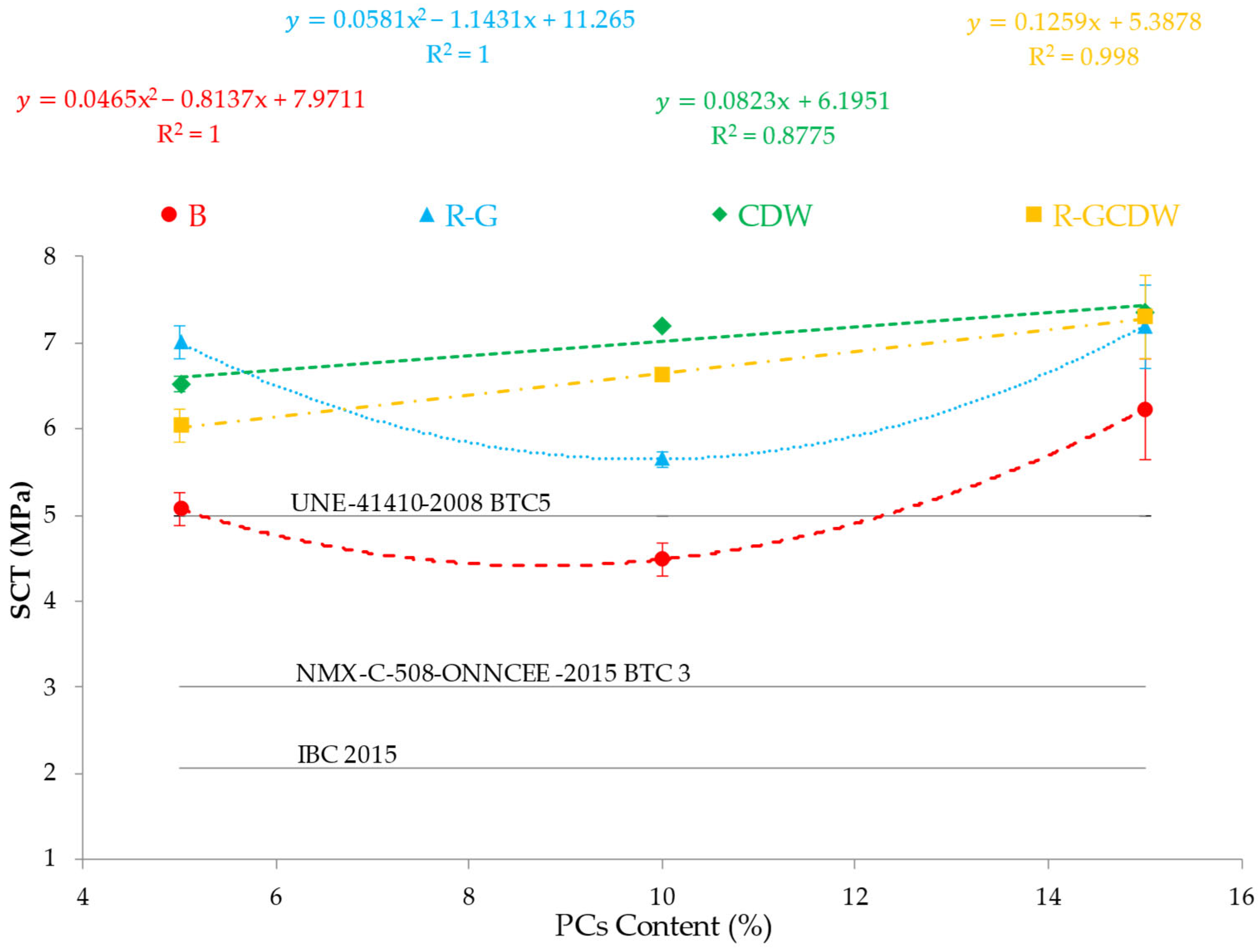
Beyond confirming similar trends from several previous studies, which originate from the diversity of materials used, the manufacturing methods, and the non-identical curing conditions, we decided to compare the results achieved for these matrices with respect to the regulations that govern them. In this sense, the NMX-C-508-ONNCCE-2015 standard (using lime as a stabilizer) [31] and UNE_41410-2008 [32] establish that the type BTC3 and BTC5 blocks must have acceptable SCT values when they achieve an SCT = 3 and 5 MPa, respectively. Therefore, with the exception of the B10 matrix, and only for BTC5, all the matrices in this research satisfy both minimum SCT limits. For BTC3, it is exceeded in all the study matrices in a range between 50 and 170%; for BTC5 the range is between 2 and 46% (B10 is not considered because it does not satisfy them). In the case of the IBC code [75], the limit of SCT = 2.06 MPa is established, which is satisfied by all the study matrices in a range between 218.4 and 354.4%. Figure 14 presents the results achieved by SCT and the limits of the different regulations.
In the previous figure, it is established that for the set of CDW and R-GCDW matrices, the trend of the relationship between the SCT and PCs is adjusted by means of directly proportional linear equations, with very strong R2 correlation coefficients [76] (typical standard error bars ( σ x ) are indicated).
The correlations that best explain the trends for B and R-G are quadratic polynomial equations; this implies that there are possible unidentified variables in these two study matrices (constant of the term x2) and so the linearity or proportionality are not directly established. This unidentified effect is of greater intensity in the R-G matrix (25% higher).
The hypothesis that governs the behavior of the CDW and R-GCDW matrices is that there is a direct and correlative link between the hydraulic capacity provided by the PC and its proportionality when used as a stabilizer, which is attributable to the new chemical bonds it produces, thereby improving the SCT of the CSEBs.
For the B and R-G matrices, and in particular for matrices with anomalous behavior (B10 and R-G10), it should be noted that a variation in measurement accuracy of up to ±3% of the applied load [46] is considered acceptable, which could explain part of the anomaly described above, in the order of 51 and 28% for B and R-G. On the other hand, the variation in the basic density of the specimens must be considered as a possible direct effect of the anomalous variability that cannot be assimilated due to regulatory error. This has several impacts on their establishment, such as non-automated mechanical compaction (duration of compaction time) of the manufacturing machine used, the balling effect [77], and the use of a volume dosing procedure. All are capable of producing changes in density, and, consequently, of SCT, not correlated with PCs. The balling effect causes material to form larger-diameter soft aggregates that, when compressed by the CSEB-making machine, lose their spherical shape and are probably converted into stacked disks. It is therefore possible that the distribution of the PCs in the different CSEB per batch will vary. Although the entire matrix was designed to contain 10% concentration, the specimens analyzed for SCT in both cases, B10 and R-G10, could have had different actual concentrations. One study [78], which obtained cement particles at different water cement ratios of 10, 15, and 20 mm in diameter, demonstrated that the fracture stress of a 10 mm diameter particle was one-third of that with a diameter of 15 mm. It is then possible that if the soft aggregates present in the B10 and R-G10 matrices are larger than those in B5 and R-G5, these particles would have a greater resistance to the compression force when they are part of the particle systems of the respective CSEB tested for SCT.

3.5. MoE

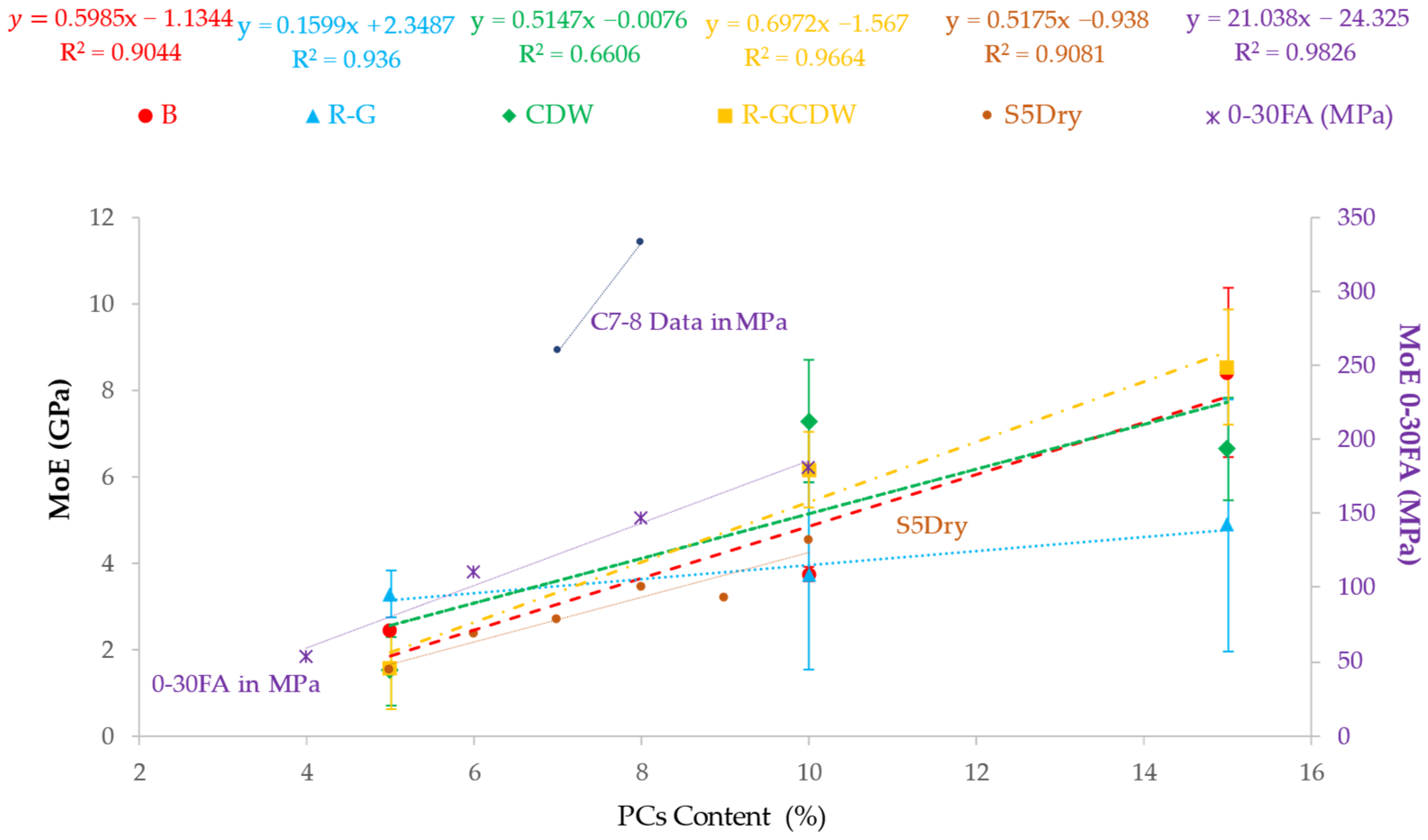
The results of the MoE show an increasing trend correlative to those of PCs for the studied matrices of B, R-G, and R-GCDW (see Figure 13). The exception is the CDW matrix, in which this trend is valid when moving to FDr, but not for the particular case of the SDr. For the specific case of matrix B, the increase achieved by moving from FDr is 54%, while passing from SDr represents 125% and TDr 247%. In the R-G matrix, FDr shows an increase of 13% and SDr of 31%, with TDr at 49%. For the R-GCDW matrix, FDr establishes an increase of 299% and SDr one of 38%, with TDr at 452%. Finally, in the CDW matrix, the FDr establishes an increase of 384%, while for an SDr it is −9%, a different trend to the rest of the matrices or PCs. With the TDr being 343%, when the entire range of PCs is considered, the trend is positive, as in the rest of the matrices. From the above, it can be said that the CDW matrix obtains the highest MoE gain speed for FDr; for SDr, it is matrix B and, overall, considering the complete range of PCs, it is the R-GCDW matrix.
From a previous study [73], in which FA was also used, it was established that MoE increases directly and correlatively with the increase in PCs. Average increases of 123, 33, and 25% with PCs from 4 to 6, from 6 to 8, and from 8 to 10%, respectively, were confirmed. On the other hand, in another study [69], the aforementioned correlation was also determined (except for the change of PCs from 8 to 9%, which established a reduction of 7%). Therefore, an increase in PCs leads to increases in MoE.
A possible explanation for this has been previously proposed [79], stating that increasing PCs produces increases in the internal connections of particles, responsible for the improvement in MoE. Calcium and silica hydrate gels are identified among the crystalline structures formed, being the ones that saturate the pores in the earth matrix. In that study (also using FA), an increase in MoE of up to 28% was reported for PCs of 5 and 7%.
Figure 15, in addition to the experimental results of this research, integrates the results of analogous studies, with MoE values ranging from 1.52 to 3.17 GPa [69], and from 210 to 375 MPa [79] (referring to the right vertical axis).
Figure 15 shows that all the study matrices can be parameterized by means of linear equations with very strong and moderate R2 correlation coefficients [76]. Regarding other studies, both S5Dry [69] and 0-30FA [73] conform to linear equations, with R2 considered very strong. All trends are directly proportional, and typical standard error bars ( σ x ) can be noted in the graph.

3.6. TC

In general terms, as these CSEBs can be considered dense blocks, they also have the possibility of a greater capacity for resistance to temperature gradients; that is, they contribute to achieving better thermal inertia, the ability to store and release temperature, in the building that integrates them. On the other hand, this thermal inertia in CSEBs is also influenced by the TC, the ease with which the material transmits heat; a CSEB with a lower TC will transmit the temperature more slowly, as higher TC will have an impact on the chances of having lower inertia. Finally, thermal inertia (energy capable of raising the material’s mass by one degree of temperature) is also influenced by the specific heat of the material itself.
The TC of the B, CDW, and R-GCDW matrices was increased for FDr by 17, 16, and 26%, respectively, and a reduction of 8% was established for the R-G matrix. For their part, the four study matrices determined increases for SDr of 9, 11, 8, and 2%, respectively. Finally, for TDr, the increases in the matrices reached 28, 2, 25, and 28%, respectively. If low TC is associated with higher insulating potential, the TC values for FDr, SDr, and TDr establish a loss in insulating potential, with an exception in FDr for the R-G matrix (see Figure 14). If all types of the study matrix are compared with the various PCs used, the R-G matrix has the lowest TC in all PCs, which means it is the matrix with the best insulating potential of the CSEBs studied.
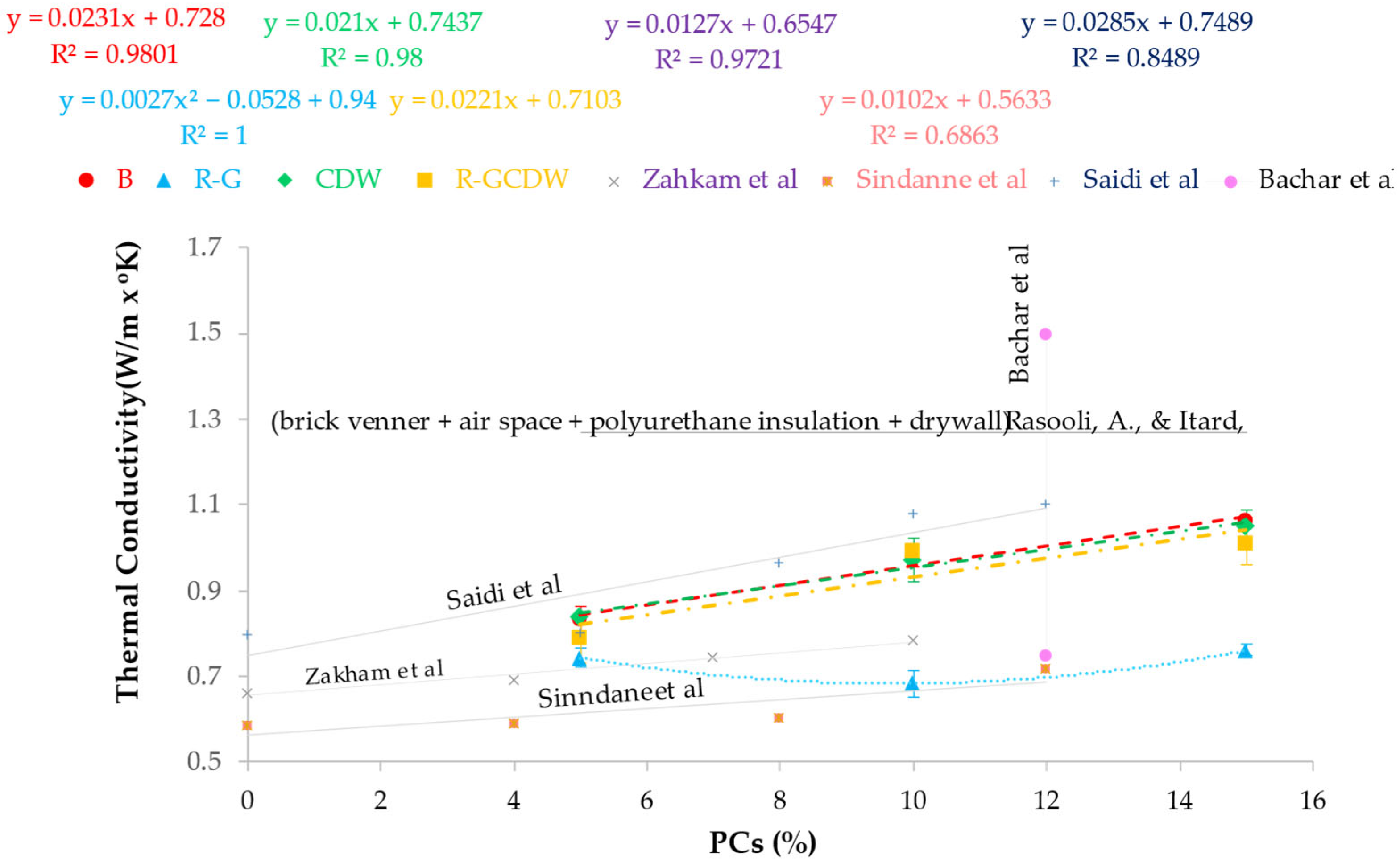
In previous research, TC was directly correlated with PC; PC values of 0, 4, 7, and 10% were studied, and TC values of 0.662, 0.692, 0.746, and 0.785 W/m·K were obtained, respectively [80]. The same trend was also established in another study [81], in which PCs of 0, 4, 8, and 12% were used, with TC values of 0.5873, 0.5900, 0.6015, and 0.7200 W/m·C. A third study [82] also confirms this relationship between PCs and TCs; on this occasion; PCs with values of 0, 5, 8, 10, and 12% were used, obtaining CTs of 0.7983, 0.8014, 0.9639, 1.0776, and 1.1000 W/m·K, respectively.
In one particular case [83] in which PCs of 12% and different concentrations of cork were used as additives, extrapolating the behavior of the values obtained from TC showed that a CSEB without additions can have TC values in the order of 0.75 to 1.50 W/m·K.
On the other hand, a reference case among wall construction systems [84] is the wall system consisting of four layers (from exterior to interior): exposed brick (10 cm thick) + air chamber (4 cm) + polyurethane insulation layer (10 cm) + drywall (9 cm), which led to established TC values of 1271 W/m·K. When compared to the matrices of this study, this value is always between 19 and 86% higher.
Figure 16 shows the TC results of the different matrices studied for each PC; the results of previous research and reference construction systems are also included as reference values.
It can be seen in the previous figure that the study matrices B, CDW, and R-GCDW can be parameterized by linear equations with very strong R2 correlation coefficients for the first two (consistent with previous studies [80,82]) and strong for the third [76] (also in other previous work [81]). In these cases, the TC variable can be explained directly with PCs, while for the R-G matrix, an equation adjustment of the second-degree polynomial type is required, as the behavior of TC cannot be explained in its entirety by the variable PCs. Finally, for the four-layer wall construction system [84], this could be considered the upper limit of reference TC for real applications, comparable to the TC values obtained in the matrices studied in this research, and typical standard error bars ( σ x ) are reported.

3.7. Microstructural Components of CSEBs

In order to verify the incidence of the microstructure of the CSEBs and their ability to predict the behavior of the properties studied, we decided to carry out an OIA study of the R-GCDW matrix in the different PCs contents. This matrix was selected because in it, the matrices performed with optimal or close to optimal values, and it was the CSEBs matrix that incorporated most of the closed-loop materials included in the research (good performance and maximum complexity). The guidelines of this study follow the recommendations of previous studies [85,86]. Images of the study matrices in tag image file format (TIFF) were used, obtained using a Seiko Epson GT20000/EU-45 scanner (Suwa, Nagano, Japan) for the surfaces exhibited (after metallographic polishing) of each tablet containing the samples embedded in epoxy resin. Considering the study surface of each tablet, the maximum image resolution permitted by the scanner, 7200 dots per inch (dpi), was used. The type of image studied was selected as 24-bit color per pixel (a pixel can vary in color by up to 224 different tones, giving a theoretical range of variability of up to 16.7 million colors). OIA was then performed on the previously-selected images, using a procedure established according to the desired objectives and applied in the Image-Pro v. 11.0.4 Build 9821 software.
To begin the study, an area of interest was established, which was delimited within the study matrix; an example is shown in Figure 17, which corresponds to the R-GCDW matrix with PCs = 15%.
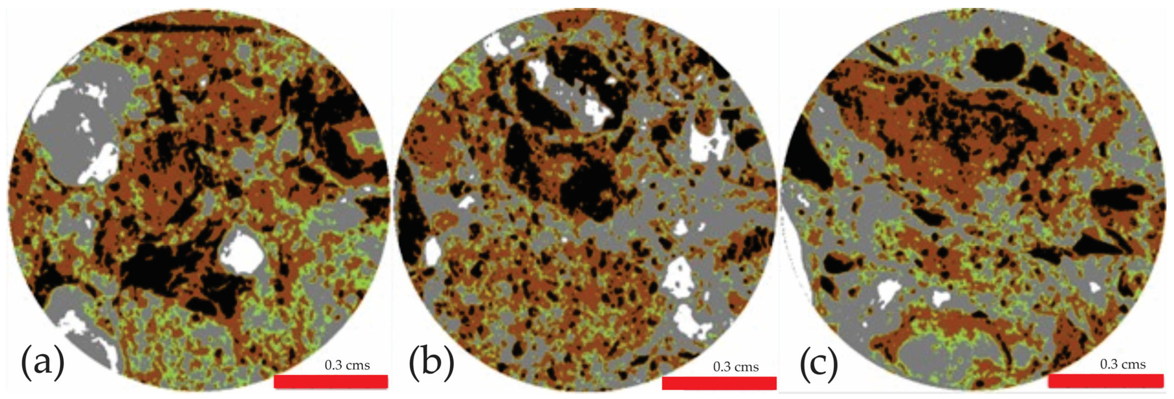
Images of the materials indicated in Figure 1 (PG, PCs, SDW, LS, R-G, CDW, SCS) were used for calibrating the different closed-loop materials. A grouping of elements was proposed that considered the following criteria by means of mono interpretation: shape of the histogram of intensities, asymmetry of the histogram of intensities, and maximum peak intensity (MPI). All the intensity histograms of the different study materials showed a platykurtic histogram shape and positive asymmetry; although they are all classified as similar, they can be sectioned into ranges for grouping, so they were the criteria applied along with the grouping ranges and the MPI. The following five element matrixes (Em) were the results of the above:
Em 1, formed due to the absence of any of the identified Em (black color). This Em 1 must be interpreted as the absence of solid material compounds, and therefore must be linked to the porosity of the matrix.
Em 2, consisting of CDW and SCS (brown). It has agglomerated distribution, forming compact packages, encircling or trapping Em 1 within them.
Em 3, made up of R-G (green, for a better contrast in the OIA study). This material is present in much of the surface of the samples studied, although a type of concentrated association pattern can be identified: it is always close to or in contact with Em 2 (surrounding Em 2 or as a border between Em 2 and Em 4).
Em 4, consisting of PCs, SDWs, and LS (gray). This Em is shown surrounding the rest of the materials, being easy to identify within the study matrices. This Em 4 is considered, within the surface of the matrices studied, to be the base in which the rest of the materials are embedded. Its distribution within the study area is extensive, surrounding the other Em.
Em 5 is composed of PG (white). Its location is concentrated and specific (it is not evenly distributed in the matrix), with large particles, and it is always surrounded by Em 4.
After establishing these guidelines to facilitate the identification of each Em within the area of interest, each of their areas was determined in percentage terms and with reference to the total area of interest of each sample. The average area of each Em (regarding the total area of interest) was 0.97 cm2 (with σ = 0.1295). Figure 18 shows the result for the R-GCDW matrices after the previously established protocols and calibrations.
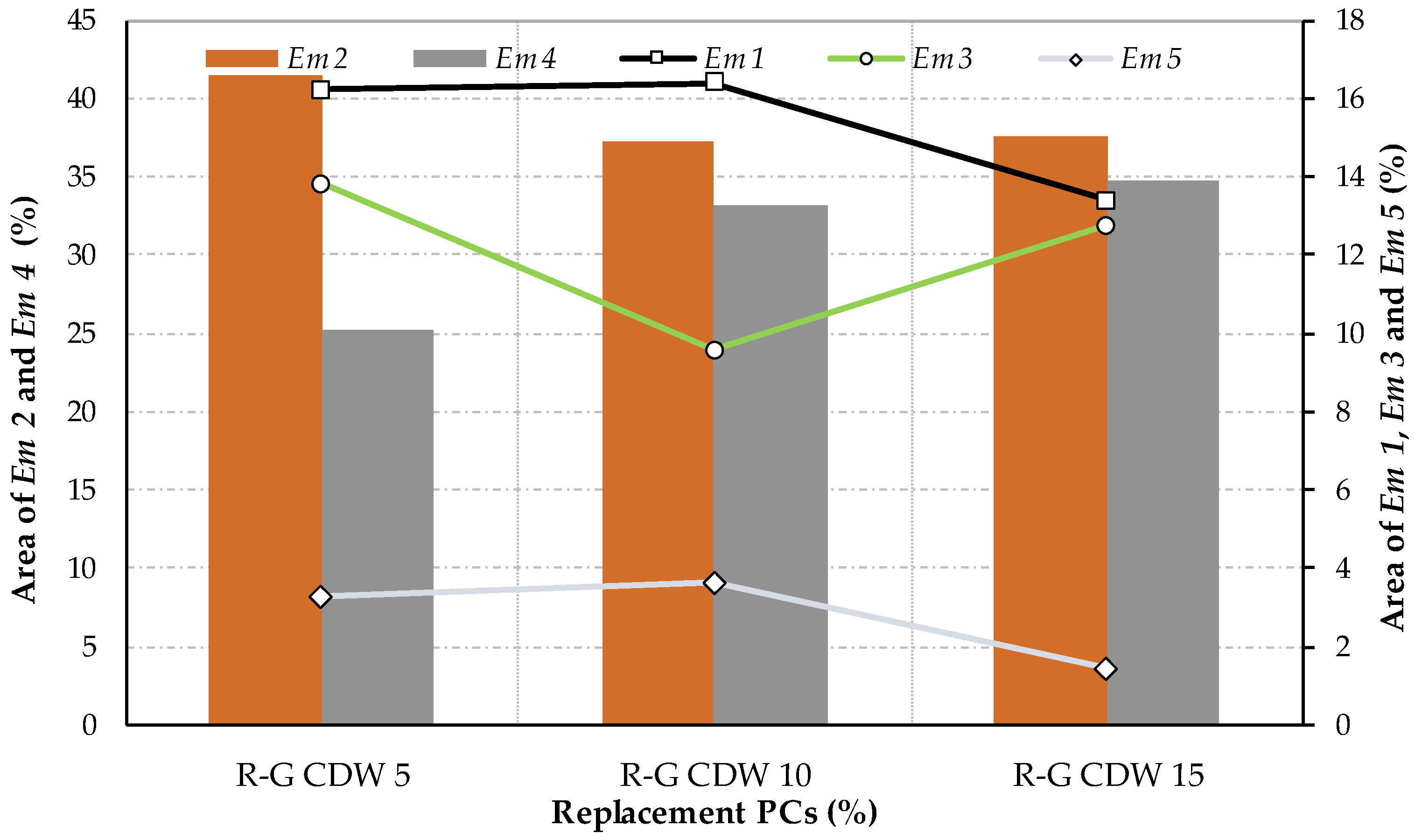
With the different Em percentages determined, Figure 19 presents them for the R-GCDW study matrices with the respective PCs contents.
The correlation equations and their R2 coefficients were determined from the results of the quantified areas (in percentage terms) of each phase identified in the matrix. Linear regressions were selected because they are regression systems with only three experimental determinations per study variable, thus avoiding a perfect fit with other types of equations that would not provide differential criteria among the matrices studied (classifications according to [76]). The correlations and their sense of correlation (inversely proportional “−” or directly proportional “+”) were as follows: for Em 1 an R2 = 0.6982 (strong or very strong) (−); for Em 2 an R2 = 0.6718 (strong or very strong) (−); for Em 3 an R2 = 0.0564 (null) (−); for Em 4 an R2 = 0.8726 (strong to very strong) (+); and, finally, for Em 5 an R2 = 0.6081 (moderate or strong) (−). With the above analysis, it is possible to infer the following premises:
For Em 1 (porosity), it is possible to establish a trend direction equal to those reported in Table 3, and to define values for some of the determinations above or below the experimental values. In general, there is a mean of −1.07% porosity for the OIA values with respect to the experimental ones (variation range between 0.90 and −3.11%). The observed porosity distribution shows different pore sizes, with large interconnected pore sizes prevailing in the samples studied, while smaller pores are scattered and isolated. The incidence of PCs is directly correlated with the reduction in interconnectivity of large pores, while at the same time propagating more small pores. This could be understood by the PC’s hydraulic capacity, which allows the creation of new compounds and, therefore, pore reduction, which is more accentuated in larger pores. Synthesizing it would indicate that the increase in PCs will produce changes in the morphology of pore sizes in the matrix, moving from larger to smaller pores.
Em 2 (CDW and SCS) achieves the highest percentage representation within the matrices studied in OIA. This alternative technique obtained values slightly above the theoretical dosage contents of the matrices, an average of 1.44% more for the three matrices, with an inverse correlation with respect to PCs and classified as strong or very strong. This allows us to consider its involvement in the results of the isolation capacity (inverse of the TC property) of the R-GCDW matrices.
Regarding Em 3 (R-G), simulating the contents of this material by means of the OIA technique established values both above and below the different matrices studied. The result was an average value of −0.72% with respect to the theoretical percentage contents of dosage. Its correlation coefficient with respect to PCs was the worst of those established in OIA, being classified as null. It should also be noted that its possible incidence as a differential component between the matrices cannot be considered significant, because this component is a constant, close or equal to the different matrices (percentage of similar content for all matrices). This should not be taken as meaning that this material has no impact on the behavior of mechanical properties, but that it has a similar impact on all of them.
In the case of Em 4 (PCs, SDW, and LS), it is second regarding the percentage representativeness within the established Em (only below Em 2). The accuracy of the OIA technique with respect to the theoretical dosage percentage values is only −0.51% (between 2.14 and −4.51%). The correlation with respect to the PCs of the matrices is positive, with a correlation coefficient considered to be very strong (the best of all those established). This combination of components, due to its significant percentage representation and its high correlation, is the best positioned in terms of explaining the mechanical properties of SCT and MoE.
Finally, Em 5 (PG) has the same percentage representation of theoretical dosage for all matrices (2.6%); the accuracy with respect to the OIA technique is 0.18% (between 1.06 and −1.17%), and the correlation established is direct and classified as moderate. Therefore, due to its low representativeness, its incidence is not considered significant for the behavior of the different properties of the matrices studied.
A regression analysis was carried out in order to establish numerical prediction equations of the studied properties of SCT, MoE, and TC that the different R-GCDW matrices may contain (considering the results obtained from the OIA study). This also includes coefficients that consider the variable of PCs. Linear equations were chosen, in which the properties to be determined considered the different Em. The requirements prescribed by the formulations took into account that each value of Em should be adjusted with a coefficient that multiplies its value, and that the resulting final predictive equation (PE) should in turn have a general coefficient that would allow the variable of PCs of the matrices (coupling of this variable) to be considered. The typology of the proposed equation is presented in Equation (1):
P E = C P C s · C E m   1 · E m   1 + C E m   2 · E m   2 + C E m   3 · E m   3 + + C E m   i · E m   i
where PE is the value of the studied property of the R-GCDW matrix, CPCs is the coefficient that considers PCs of each matrix, CEm i is the coefficient determined by numerical adjustment for each of the Em established in the OIA study, and Em i is the percentage value of the area of each Em as determined in the OIA study.
To obtain the PEs, Solver’s 2025 Q1 [59] software was used, which uses numerical adjustment subroutines to continuously approximate cycles and refine amendment protocols. With this software, it is possible to determine pre-established alternative scenarios, with acceptance criteria to distinguish the most-adjusted numerical solution from which the CEM i and the CPCs can be obtained for each PE of the matrix property R-GCDW. The extreme ranges of each variable considered by the experimental variables (Figure 14, Figure 15 and Figure 16), the criteria for making the approximation, the selected method of resolution (non-linear), the algorithm’s repetition parameters (minimum acceptable convergence error of 0.0001), evaluation of i + 1 repetition by approximation (always forward), and the initial value of the variables to be determined (equal to zero) all followed the guidelines applied to a similar, previous, numerical procedure [87].
As a first approximation, all the Em established in OIA were considered; however, as it is a system with three observations (PCs) for each study property and six constants that allow adjustment to the OIA Em, it could be considered an overfitting system, which means that the PE fits perfectly to the data, but could behave erratically outside of it (low reliability). Therefore, and considering what was established above for Em 5 (identical and very low percentage representation of dosage for the PCs studied), we decided not to consider this M in the regression analysis for obtaining the PEs. From the above, the following equations were obtained.
For SCT (Equation (2)):
SCT = C P C s · 0.3119   · E m   1 + 0.2665 · E m   2 + 0.4482 · E m   3 + 0.7942 · E m   4
The interpretation of the incidence of the coefficients and variables of the equation was studied by separately making each Em vary incrementally (keeping the Em not studied in the equation as constant and observing the result of SCT). The deductions regarding the effects of the Em on SCT are that the CPCs coefficient allows the model to be adjusted to a general scale. Regarding the CEm 1 coefficient, the variable Em 1 has a negative descending effect, classified by its slope as moderate on the property of SCT (the higher the Em 1, the lower the SCT). The coefficient CEm 2 has a lower effect due to its slope, while the slope of CEm 3 gives a moderate effect and CEm 4 is the strongest, with an effect considered greater due to its slope. The three previous coefficients have a positive, ascending, effect on SCT, which indicates that increasing the Em related to these coefficients will increase SCT.
Similarly, a sensitivity analysis was performed to corroborate the degree of strength or power that each Em used in the PE has to achieve changes in the SCT value. This resulted in the following order (from highest to lowest SCT power of change): Em 4 is considered the variable with the most power, the motor of change of SCT, while Em 3 has a “mild” effect. Em 1 has a moderate effect if compared to Em 4, but should not be ignored because it is a negative effect. Em 2 is considered mild. In summary, they could be expressed as follows: Em 4 > Em 3 > Em 1 > Em 2.
Therefore, to achieve improvements in SCT, the focus should be on increasing, controlling, or optimizing the Em 4 variable (PCs, SDW, and LS). Finally, it should be noted that this study has limitations: the equation could continue to have the overfitting effect (although less than with five variables), as well as a possible multicollinearity effect that has not been studied (simultaneous interaction between variables).
For MoE (Equation (3)):
MoE = C P C s · 1.115 · E m   1 0.675 · E m   2 + 0.430 · E m   3 + 1.781 · E m   4
The interpretation of the different variables of Em obtained from OIA would be as follows: Em 4 has the strongest positive effect, amplified by CPCs with respect to the ability to increase the value of MoE; this is the motor of change of the equation. Em 1 has a moderate negative effect, and is the second strongest. Em 2 also has a negative effect, but weaker than that of Em 1. Em 3, which has a moderate positive effect, is the smallest of all Ems. In summary, they could be expressed as follows: Em 4 > Em 1 > Em 2 > Em 3.
Therefore, to achieve improvements in MoE, the objective should be to increase, control, or optimize the Em 4 variable (PCs, SDW, and LS); alternatively, the reduction in Em 1 can also be promoted, although it does not have the same effectiveness as Em 4. Finally, it should also be noted that this argument has the same limitations as the previous SCT equation.
Finally, for TC (Equation (4)):
TC = C P C s · 0.0533 · E m   1 0.0369 · E m   2 + 0.0473 · E m   3 + 0.0215 · E m   4
In this case, the Em variables obtained from OIA should be interpreted as follows. As what is ideally sought in a material is a low TC, the following order of factors is used to reduce this TC. Em 2 is the only one that has a negative effect, although this is considered to be quite significant, as increases in Em 2 will result in a reduction in TC. The rest of the Ems have a positive effect (they increase TC) in the following order: Em 1 is the most significant or strongest of all the Ems, Em 3 is moderate, and Em 4 is the lowest of all. The order would be Em 2 < Em 4 < Em 3 < Em 1. If, on the other hand, low TC values are not sought, but only the order in which the Em can make changes in TC, then the order of the variables would be Em 1 > Em 2 > Em 3 > Em 4. Regarding the sensitivity of change of each Em, the order is as follows: Em 3 has the greatest positive effect on the TC change, Em 2 is the second variable with the greatest capacity for change (negative), and, finally, Em 1 and Em 4 contribute to the change, but to a lesser extent than Em 3.
Therefore, increases in the variable Em 2 (CDW and SCS) should be proposed in order to achieve improvements in TC (reduction). In this case, the same limitations as in the previous equations must be taken into account.
The prescribed coefficients of the above equations for the different R-GCDW matrices studied are presented in Table 4.
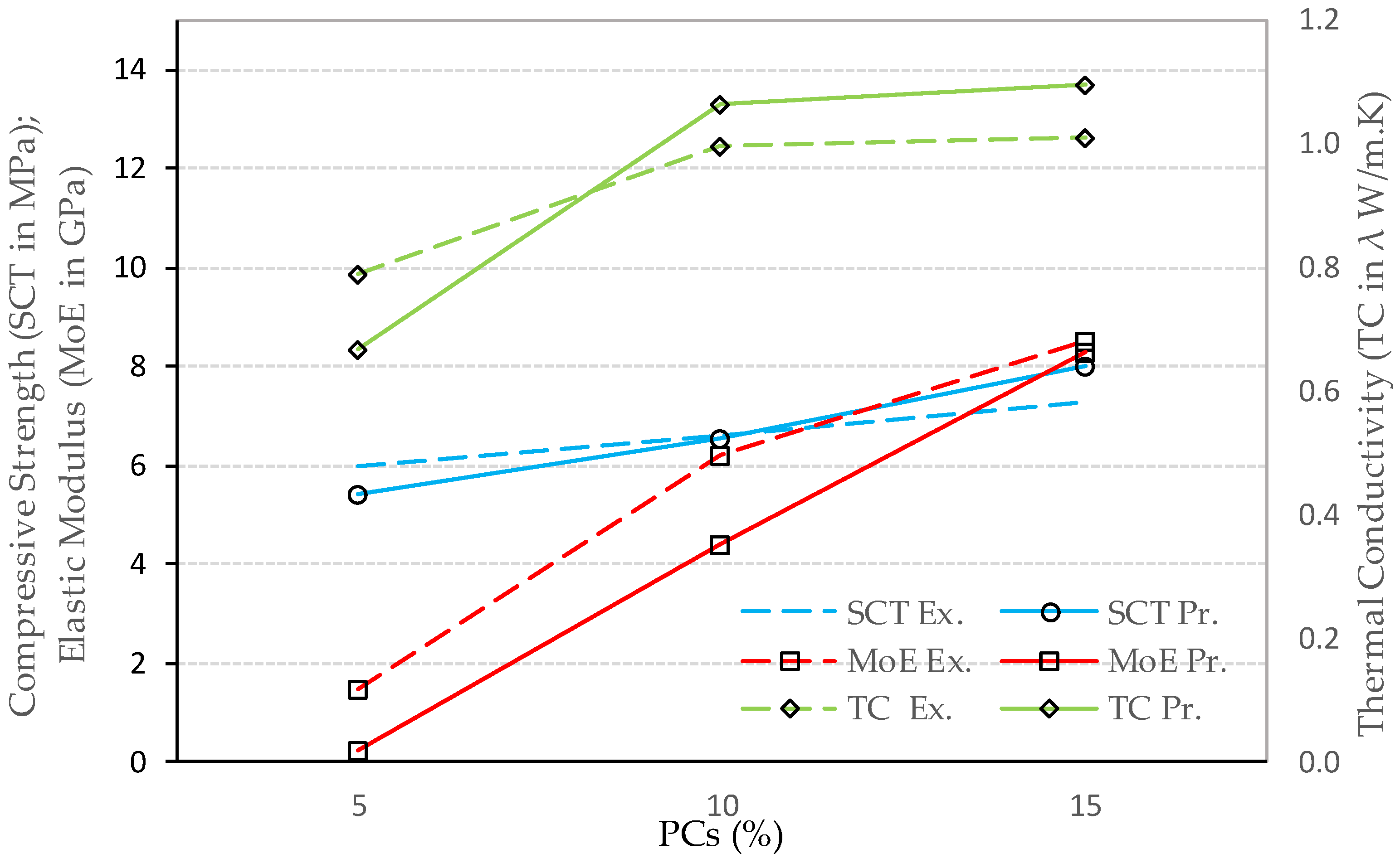
Figure 20 presents the values of the experimental (Ex.) results obtained in the laboratory tests, and the predictive (Pr.) obtained with the adjustments of each equation for the matrices studied, thus allowing the validation or the degree of adjustment between Ex. and Pr.
The OIA performed in this research, as explained above, provides qualitative information about the pore structure such as a distinction of sizes and distribution, and quantitatively regarding the calculated porosity as a percentage; it is consistent and of inverse proportion with the increase in PCs. Zhen Huang et al. [88] used a computer tomography scan; the output images were imported with reconstruction software, then denoised to enhance pore characteristics. They were able to predict that density is proportional to the thermal conductivity because the pores decreased. A study on reconstituted clays predicted the compression behavior by determining the size and distribution of the pores [89]. Similarly, it can be asserted that the OIA is a secondary technique that allows identifying the components of materials in the matrix microstructure, ordering them according to significance or importance and using them as components that provide solutions to prediction equations for the behavior of R-GCDW properties.

3.8. Rating

If it is decided to establish a global evaluation that includes all the variables studied, the desirable values of certain properties are not necessarily associated with a condition of generalized improvement. For example, the increase in TC from increasing the concentration of PCs may be detrimental to the thermal insulating capacity of the CSEBs, which could be an acceptable decision when it is necessary to prioritize the SCT.
Establishing systems to categorize different attributes and facilitate decision making has been proposed as a valid method in previous research [90]; therefore, it was applied in four of the six properties studied: AbsCoeff10, SCT, MoE, and TC. Density is excluded, because it is integrated into the calculation of MoE, as is porosity, because it is considered to have an effect on the physical-mechanical properties (AbsCoef10, SCT) and thermal performance (TC), as indicated in a previous study [91] cited in [92].
In the analysis, a rating scale based on 100 (a criterion also used previously [93]) was selected, with a maximum value of SCT and MoE of 100 points. The minimum unit is established as a value of 50 (value set for exceeding the minimum criteria for compliance with regulations, contrasted with the experimental results obtained), which corresponds to the lowest established experimental property.
For the property of AbsCoeff10, with inverse proportionality with respect to PCs and the TC that establishes better insulating potential at lower values, the lowest experimental value of the properties is assigned 100 points, and the highest 50 points. Next, the rest of the intermediate values of each property are established by interpolation, assigning them the equivalent points.
To achieve the global evaluation, it is necessary to establish a weighting by significance of the properties to be included in the analysis [94]. Therefore, it was considered that the properties of MoE and SCT are linked to the composition of the matrices and the production method of the CSEBs [95]; the AbsCoeff10 is linked ([96] cited in [97]) to the composition and microstructure of the CSEB matrices, and the TC value of the CSEBs allows evaluation of the ideal level of thermal insulation [98] linked to their microstructure. Therefore, considering all of the above, it is proposed that each property should provide information and links of similar importance, so it is established that the weighting value is the same for the four properties.
Figure 21 shows an example of the rating based on 100 and an equal weighting among the four properties.
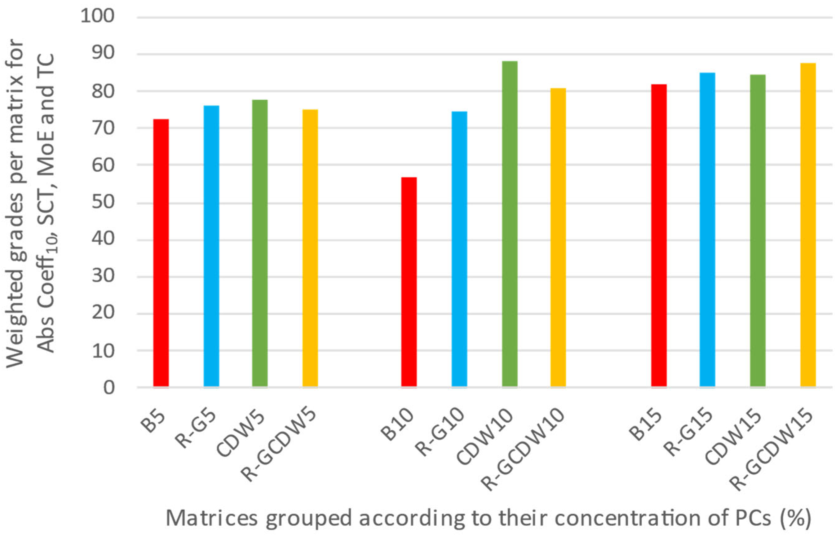
An analysis of attributes was selected for visualization in a single figure, a procedure that was validated in the study with samples of even greater complexity [99]. In particular, this research considered twelve matrices and four properties. Figure 22 presents the grouped results considering the three concentrations of PCs, in order to allow this analysis to establish the weighted degree of performance of the matrices studied.
From the comparison of the scores established in RG, CDW, and R-GCDW with those achieved by B, it can be deduced that substituting natural materials with second-generation aggregates (which integrate PCs) will always improve the former’s performance. In particular, for the concentration of PCs of 5%, R-G, CDW, and R-GCDW obtain increases of 3.86, 5.38, and 2.84, respectively, with regard to B. When PCs is 10%, in the same order, they outperform B by 17.73, 31.21, and 24.21 points. Finally, when PCs is 15%, again in the same order, the points are exceeded by 3.37, 2.79, and 5.85. Therefore, this weighted performance grade analysis establishes a positive potential use of second-generation materials, thus reducing the pressure on natural resources. Similarly, from a broader environmental perspective (reduction in PC usage), substantial improvements in matrix B with up to 10% content could be considered the most environmentally friendly upper limit, as increasing PCs by 10 to 15% (50% more PC content) does not achieve proportional improvements in weighted performance, only attaining increases in scores of 19, 9, and 24% for R-G, CDW, and R-GCDW, respectively.

4. Conclusions

Although the tests are performed by protecting the materials used from the effects of the sun and rain, in addition to the CSEBs themselves (with the exception of PCs, which were kept in a dry condition), the feasibility of manufacturing them with local closed-loop materials and curing them in situ is validated, without the need to control relative humidity and temperature in a humid and hot climate.
The balling effect impacts the homogeneity and rheology of the mixture and causes variability in the distribution of post-mixed particles of the different CSEB matrices, while the semi-automatic molding system for compacting the CSEBs is another source of variability.
In terms of CSEB density, all matrices exceed the minimum limit of SL Standard 1382 Part 1 [60].
Regarding apparent porosity, B, CDW, and R-GCDW (but not R-G) established inverse trends proportional to the increase in PCs. In general, porosity established a generalized reduction in the study matrices due to the contribution of PCs, which have the ability to form new compounds that close the spaces between aggregate particles. However, this favorable contribution of the PC to porosity can be affected by factors such as the shape of the particles (elongation) or their surface roughness, capable of forming different layers with a variety of resistant properties during the compaction process.
For the CoefAbs10 property, R-G presented the most significant inverse decrease to the content of PCs, compared to the rest of the matrices.
In this study, the R-G, CDW, and R-GCDW matrices, as well as B5 and B15, exceeded the limits established by different regulations [31,32,75] regarding SCT; this property is considered to be the generalized acceptance test for validating the use of CSEBs as suitable for the construction of load-bearing walls. In addition, CDW and R-GCDW established a direct correlation with respect to PCs. The above behavior has already been explained in previous research [100], cited in [101], which attributed it to the formation of hydrated calcium and aluminum silicates that are present together with geopolymeric gels, forming a three-dimensional network of aluminosilicates.
The MoE for all the matrices studied established direct and linear correlations with respect to PCs. The variability of the values obtained for the different formulations is a consequence of the diversity of the formulations themselves, as well as of the non-automated mechanization of the compression duration control in the CSEB production machine. Therefore, MoE is influenced by the heterogeneity of CSEBs, which is characteristic of an orthotropic material [102].
The R-G TC is the lowest of all PC concentrations compared to B, CDW, and R-GCDW. TC has a direct relationship with PCs, which responds to the microstructure of the matrix, as PCs produce a more continuous and less porous material; therefore, heat transmission is easier.
According to the results presented for R-GCDW, it can be stated that the OIA technique is a secondary technique that allows the identification of material components in the matrix microstructure. This was established by ordering them by significance and using them as components that solved equations for predicting the behavior of the analyzed properties.
From the analysis that combined the studied properties (AbsCoef10, SCT, MoE, and TC), it was established that all the matrices that replaced natural materials with second-generation materials achieved better performance. Limiting the concentration of PCs to a maximum of 10% (to the detriment of a lower assimilable performance) was established as the most sustainable criterion.
For future lines of research, we propose to extend and combine these studies with other techniques of microstructural characterization of the matrices, including those that allow identifying the changes of their matrix with respect to the use of PCs. We also plan to determine the presence of new compounds formed from the interaction of aggregates, water, and PCs, in order to fully understand the interactions established in the CSEB matrices.

Author Contributions

Conceptualization, J.M.G.-S. and M.N.R.-V.; methodology, J.M.G.-S. and M.N.R.-V.; formal analysis, C.R.-R. and J.M.G.-S.; investigation, J.M.G.-S. and M.N.R.-V.; resources, J.M.G.-S., M.N.R.-V. and C.R.-R.; data curation, C.R.-R. and J.M.G.-S.; writing—original draft preparation, J.M.G.-S. and C.R.-R.; writing—review and editing, J.M.G.-S. and C.R.-R.; visualization, M.N.R.-V. and C.R.-R.; supervision, J.M.G.-S. and M.N.R.-V. All authors have read and agreed to the published version of the manuscript.

Funding

This research received no external funding.

Conflicts of Interest

The authors declare no conflicts of interest.

References

  1. Morel, J.C.; Mesbah, A.; Oggero, M.; Walker, P. Building houses with local materials: Means to drastically reduce the environmental impact of construction. Build. Environ. 2001, 36, 1119–1126. [Google Scholar] [CrossRef]
  2. Zhang, Y.; Jiang, S.; Quan, D.; Fang, K.; Wang, B.; Ma, Z. Properties of Sustainable Earth Construction Materials: A State-of-the-Art Review. Sustainability 2024, 16, 670. [Google Scholar] [CrossRef]
  3. EPA United States Environmental Protection Agency. Sustainable Management of Construction and Demolition Materials. Available online: https://www.epa.gov/smm/sustainable-management-construction-and-demolition-materials (accessed on 24 September 2024).
  4. Louisiana Department of Environmental Quality Office of Environmental Services Waste Permits Division (LDEQ Louisiana), 2023. 2021 Biennial Solid Waste Capacity Report (Fiscal Year 2020 & Fiscal Year 2021) to the House Natural Resources and Environment Committee and Senate Committee on Environmental Quality. Available online: https://www.deq.louisiana.gov/assets/docs/Land/CapacityReport2021.pdf (accessed on 24 September 2024).
  5. Federal Highway Administration, Publications, Research Publications. User Guidelines for Waste and Byproduct Materials in Pavement Construction. Publication Number: FHWA-RD-97-148. Available online: https://www.fhwa.dot.gov/publications/research/infrastructure/pavements/97148/053.cfm (accessed on 24 September 2024).
  6. Panghal, H.; Kumar, A. Sustainable Concrete: Exploring Fresh, Mechanical, Durability, and Microstructural Properties with Recycled Fine Aggregates. Period. Polytech. Civ. Eng. 2024, 68, 543–558. [Google Scholar] [CrossRef]
  7. González-Martínez, M.A.; Gómez-Soberón, J.M.; Leal-Castañeda, E.J. Permeable Concrete with Recycled Aggregates. Study of Its Mechanical and Microstructural Properties. Materials 2025, 18, 770. [Google Scholar] [CrossRef]
  8. Wei, M.; Chen, L.; Lei, N.; Li, H.; Huang, L. Mechanical properties and microstructures of thermally activated ultrafine recycled fine powder cementitious materials. Constr. Build. Mater. 2025, 475, 141195. [Google Scholar] [CrossRef]
  9. Marey Mahmoud, H.H.; Kamel, A.M.A.; Ali, M.F. Developing Low-Cost Eco-friendly Restoration Mortars for Historic Lime-based Stucco and Building Materials. Period. Polytech. Civ. Eng. 2024, 68, 657–668. [Google Scholar] [CrossRef]
  10. Aninda, S.S.; Islam, M.S. Effectiveness of waste concrete powder in fabricating compressed stabilized earth blocks: Strength, durability and thermal assessment. J. Build. Eng. 2023, 80, 107989. [Google Scholar] [CrossRef]
  11. Coherent, M.I. United States Container Glass Market Size and Share Analysis—Growth Trends and Forecasts (2025–2032). 2023. Available online: https://www.coherentmi.com/industry-reports/united-states-container-glass-market (accessed on 24 September 2024).
  12. Wildman, J.C. Laboratory Evaluation of Recycled Crushed Glass Cullet for Use as an Aggregate in Beach Nourishment and Marsh Creation Projects in Southeastern Louisiana. Master’s Thesis, University of New Orleans, New Orleans, LA, USA, December 2018. Available online: https://scholarworks.uno.edu/td/2565 (accessed on 20 May 2024).
  13. Mohajerani, A.; Vajna, J.; Cheung, T.H.H.; Kurmus, H.; Arulrajah, A.; Horpibulsuk, S. Practical recycling applications of crushed waste glass in construction materials: A review. Constr. Build. Mater. 2017, 156, 443–467. [Google Scholar] [CrossRef]
  14. Alducin-Ochoa, J.M.; Martín-del-Río, J.J.; Torres-González, M.; Flores-Alés, V.; Hernández-Cruz, D. Performance of mortars based on recycled glass as aggregate by accelerated decay tests (ADT). Const. Build. Mater. 2021, 300, 124057. [Google Scholar] [CrossRef]
  15. Gómez-Soberón, J.M.; Cabrera-Covarrubias, F.G.; Luis Almaral-Sánchez, J.; Gómez-Soberón, M.C. Fresh-State Properties of Mortars with Recycled Glass Aggregates: Global Unification of Behavior. Adv. Mater. Sci. Eng. 2018, 2018, 1386946. [Google Scholar] [CrossRef]
  16. Cabrera-Covarrubias, F.G.; Gómez-Soberón, J.M.; Almaral-Sánchez, J.L.; Arredondo-Rea, S.P.; Mendivil-Escalante, J.M. Mechanical and Basic Deformation Properties of Mortar with Recycled Gass as a Fine Aggregate Replacement. Int. J. Civ. Eng. 2018, 16, 107–121. [Google Scholar] [CrossRef]
  17. Redondo-Pérez, N.M.; Redondo-Mosquera, J.D.; Abellán-García, J. A Comprehensive Overview of Recycled Glass as Mineral Admixture for Circular UHPC Solutions. Sustainability 2024, 16, 5077. [Google Scholar] [CrossRef]
  18. Larbi, S.; Khaldi, A.; Maherzi, W.; Abriak, N.E. Formulation of compressed earth blocks stabilized by glass waste activated with NaOH solution. Sustainability 2022, 14, 102. [Google Scholar] [CrossRef]
  19. Ellwood, B.B.; Warny, S.; Hackworth, R.A.; Ellwood, S.H.; Tomkin, J.J.; Bentley, S.J.; Braud, D.H.; Clayton, J. The LSU Campus Mound with construction beginning at ~11,000 BP, are the oldest known extant man-made structures in the Americas. Am. J. Sci. 2022, 322, 795–827. [Google Scholar] [CrossRef]
  20. Smith, E.W.; Austin, G.S. Adobe, Pressed-Earth, and Rammed-Earth Industries in New Mexico; Revised Edition; Bulletin 159; New Mexico Bureau of Mines & Mineral Resources: Socorro, NM, USA, 1996. [Google Scholar]
  21. Montoya-Pino, M.P.; Ramírez-Nieto, J.V.; Aravecchia-Botas, N.C. CINVA: Un proyecto latinoamericano 1951–1972 (CINVA: A Latin-American Project 1951–1972). 2024. Radio Podcast from Universidad Nacional de Colombia, radio UNAL. Available online: https://radio.unal.edu.co/detalle/cinva-un-proyecto-latinoamericano-1951-197 (accessed on 25 September 2024).
  22. Galindo-Díaz, J.; Escorcia-Oyola, O.; González-Calderón, A.J. The Inter-American Housing Center (CINVA) and the origins of the experimentation with compressed earth blocks (CEB) in social dwelling (1953–1957). Inf. Constr. 2023, 75, 570. [Google Scholar] [CrossRef]
  23. Peña Rodríguez, M.L. El Programa CINVA y la acción communal (The CINVA program and the community action). Bit. Urb. Terr. 2008, 12, 185–192. [Google Scholar]
  24. Kimmons, G.L.; Ferm, R.L.; Matteson, R. Asphalt-stabilized building blocks. Ind. Eng. Chem. Prod. Res. Dev. 1969, 8, 3. [Google Scholar] [CrossRef]
  25. Reyna-Ruiz, C.; Gómez-Soberón, J.M.; Rojas-Valencia, M.N. Feasibility and Application of Local Closed-Loop Materials to Produce Compressed and Stabilized Earth Blocks. Materials 2024, 17, 3358. [Google Scholar] [CrossRef] [PubMed]
  26. Cabrera, S.; Darras, G.; Losa, N. Evaluation of the pressing process in the manufacture of compressed earth blocks. Inf. Constr. 2024, 76, 574. [Google Scholar] [CrossRef]
  27. Walker, P.; Stace, T. Properties of some cement stabilized compressed earth blocks and mortars. Mater. Struct. 1997, 30, 545–551. [Google Scholar] [CrossRef]
  28. ASTM-C 150-07; Standard Specification for Portland Cement. ASTM International: West Conshohocken, PA, USA, 2007.
  29. ISO 2591-1:1988; International Standard ISO 2591-1, First Edition 1988 12-01. Test sieving—Part 1: Methods Using Test Sieves of Woven Wire Cloth and Perforated Metal Plate. International Organization for Standardization: Geneva, Switzerland, 1998.
  30. Maïni, S. Production and Use of Compressed Stabilized Earth Blocks, Code of Practice; Auroville Earth Institute: Auroville, India, 2010. [Google Scholar]
  31. NMX-C-508-ONNCE-2015; Norma Mexicana-Industria de la Construcción—Bloques de Tierra Comprimida Estabilizados con Cal—Especificaciones y Métodos de Ensayo (Mexican Norm for the Construction Industry, Compressed Earth Blocks, Stabilized with lime—Specifications and Test Methods). Organismo Nacional de Normalización y Certificación de la Construcción y la Edificación, S.C.: Ciudad de México, México, 2015.
  32. UNE 41410-2008; Bloques de Tierra Comprimida para Muros y Tabiques. Definiciones, Especificaciones y Métodos de Ensayo. Norma Española: Madrid, Spain, 2008.
  33. Kaifan, A.; Gani, F.A.; Irham; Munardy. The Stabilization of Compressed Stabilized Earth Blocks using rice husk ash-lime-cement to reduce environmental pollution. IOP Conf. Ser. Earth Environ. Sci. 2025, 1510, 012091. [Google Scholar] [CrossRef]
  34. Sadouri, R.; Kebir, H.; Benyoucef, M. The Effect of Incorporating Juncus Fibers on the Properties of Compressed Earth Blocks Stabilized with Portland Cement. Appl. Sci. 2024, 14, 815. [Google Scholar] [CrossRef]
  35. Labiad, Y.; Meddah, A.; Beddar, M. Performance of sisal fiber-reinforced cement-stabilized compressed-earth blocks incorporating recycled brick waste. Innov. Infrastr. Solut. 2023, 8, 107. [Google Scholar] [CrossRef]
  36. Kumar, N.; Barbato, M. Effects of sugarcane bagasse fibers on the properties of compressed and stabilized earth blocks. Constr. Build. Mater. 2022, 315, 125552. [Google Scholar] [CrossRef]
  37. Kasinikota, P.; Tripura, D.D. Prediction of physical-mechanical properties of hollow interlocking compressed unstabilized and stabilized earth blocks at different moisture conditions using ultrasonic pulse velocity. J. Build. Eng. 2022, 48, 103961. [Google Scholar] [CrossRef]
  38. Ma, J.; Abdelaal, A.; Zhang, H.; Zhou, A.; Fu, Y.; Xie, Y.M. Ultra-compressed earth block stabilized by bio-binder for sustainable building construction. Case Stud. Constr. Mater. 2024, 21, e03523. [Google Scholar] [CrossRef]
  39. Sathiparan, N.; Tharuka, R.A.N.S.; Jeyananthan, P. Prediction of moisture content of cement-stabilized earth blocks using soil characteristics, cement content, and ultrasonic pulse velocity. J. Eng. Appl. Sci. 2024, 71, 187. [Google Scholar] [CrossRef]
  40. Cruz, R.; Bogas, J.A.; Balboa, A.; Faria, P. Water Resistance of Compressed Earth Blocks Stabilised with Thermoactivated Recycled Cement. Materials 2024, 17, 5617. [Google Scholar] [CrossRef] [PubMed]
  41. WU Weather Underground. Kenner, LA Weather History. Available online: https://www.wunderground.com/history/monthly/us/la/kenner/KMSY/ (accessed on 30 June 2023).
  42. Nshimiyimana, P.; Hema, C.; Sore, S.O.; Zoungrana, O.; Messan, A.; Courard, L. Durability Performances of Compressed Earth Blocks Exposed to Wetting-Drying Cycles and High Temperature. WIT Trans. Built Environ. 2022, 210, 141–149. [Google Scholar] [CrossRef]
  43. Nshimiyimana, P.; Djibo, K.B.; Sore, S.O.; Coulibaly, Y.; Pru’Homme, E.; Zhao, Z.; Messan, A.; Courard, L. High-Temperature Performances of Compressed Earth Blocks Stabilized with Cementitious Binders. In Second RILEM International Conference on Earthen Construction. ICEC 2024, Edinburgh, UK, 8–10 July 2024; Beckett, C., Bras, A., Fabbri, A., Keita, E., Perlot, C., Perrot, A., Eds.; RILEM Book Series; Springer: Cham, Switzerland, 2024; Volume 52. [Google Scholar] [CrossRef]
  44. UNE-EN-ISO 18754:2022; Cerámicas Técnicas (cerámicas avanzadas, cerámicas técnicas avanzadas) Determinación de la densidad y de la porosidad aparente. Asociación Española de Normalización: Madrid, Spain, 2022.
  45. NMX-C-037-ONNCCE-2013; Industria de la Construcción—Mampostería—Determinación de la absorción total y la absorción inicial de agua en bloques, tabiques o ladrillos y tabicones—Método de Ensayo. Norma Mexicana: Naucalpan de Juárez, Mexico, 2013.
  46. NMX-C-036-ONNCCE-2013; Industria de la Construcción—Mampostería—Resistencia a la compresión de bloques, tabiques o ladrillos y tabicones y adoquines—Método de ensayo. Norma Mexicana: Naucalpan de Juárez, Mexico, 2013.
  47. Speevak, T.; Yu, A.K. Multiple Attributes Sampling Acceptance Plans Involving Destructive Testing. Technometrics 1987, 29, 103–107. [Google Scholar] [CrossRef]
  48. Warren, W.G. Sampling Strategies for Destructive Tests; Environment Canada, Forestry Directorate, Western Forest Products Laboratory: Vancouver, BC, Canada, 1975. [Google Scholar]
  49. Bayiha, B.N.; Kenmogne, F.; Bahel, B.; A’Paglan Bidime, É.Y.; Bell, E.Y.; Billong, N. Development and characterization of a composite material with geopolymer matrix obtained by incorporation of microparticles from plastic bottles. Heliyon 2024, 10, e30801. [Google Scholar] [CrossRef]
  50. Adesina, F.; Mohammed, T.I.; Ojo, O.T. Design and Fabrication of a Manually Operated Hydraulic Press. Open Access Libr. J. 2018, 5, e4522. [Google Scholar] [CrossRef]
  51. Debele, A.D.; Demeke, S.; Bekele, T.; Malimo, M. Recycling and reusing potential of disposable low-density polyethylene plastic waste for flexible paver tile construction for outdoor application. Heliyon 2024, 10, e29381. [Google Scholar] [CrossRef] [PubMed]
  52. Khatib, M.I.; Ahmed, R.Z.; Uddin, M.S.; Abdul Rahman, M.; Shareef, M.R.; Akber, S.; Khan, M.; Shaikh, S. Design and Fabrication of 5 Ton Hydraulic Press Machine. Int. J. Sci. Res. Sci. Eng. Technol. 2020, 7, 22–30. [Google Scholar] [CrossRef]
  53. Sumaila, M.; Okonigbon, A.; Ibhadode, A. Design and Manufacture of a 30-ton Hydraulic Press. Au J. Technol. 2011, 14, 196–200. [Google Scholar]
  54. ASTM C597-22; Standard Test Method for Ultrasonic Pulse Velocity Through Concrete. ASTM International: West Conshohocken, PA, USA, 2022.
  55. ASTM E494-15; Standard Practice for Measuring Ultrasonic Velocity in Materials. ASTM International: West Conshohocken, PA, USA, 2015.
  56. Bowen, P.K. Engineering Elastic Constants from Ultrasonic Wave Velocity. Deringer-Ney Tech Briefs. 2015. Available online: https://deringerney.com/engineering-elastic-constants-from-ultrasonic-wave-velocity (accessed on 15 February 2025).
  57. Hak-Chul, S.; Yoonseok, C. Determination of Coefficient of Thermal Expansion Effects on Louisiana’s PCC Pavement Design. Department of Civil and Environmental Engineering, Louisiana State University, Baton Rouge Louisiana, 70803 2011, State Project No 736-99-1450 conducted for Louisiana Department of Transportation and Development Louisiana Transportation Research Center. Available online: https://rosap.ntl.bts.gov/view/dot/23571 (accessed on 4 August 2025).
  58. He, H.; Dyck, M.; Lv, J. The heat pulse method for soil physical measurements: A bibliometric analysis. Appl. Sci. 2020, 10, 6171. [Google Scholar] [CrossRef]
  59. Solver, version 2025 Q1; Frontline Solvers: Reno, NV, USA, 2025. Available online: https://www.solver.com (accessed on 6 May 2025).
  60. SLS 1328:1:2009; Specification for Compressed Stabilised Earth Blocks: Part 1: Requirements. Sri Lanka Standards Institution: Colombo, Sri Lanka, 2009.
  61. Malkanthi, S.N.; Wickramasinghe, W.G.S.; Perera, A.A.D.A.J. Use of construction waste to modify soil grading for compressed stabilized earth blocks (CSEB) production. Case Stud. Constr. Mater. 2021, 15, e00717. [Google Scholar] [CrossRef]
  62. Davis, L.K.; Maïni, S. Feasibility Report for Compressed Stabilized Earth Block (CSEB) Production and Use in the North and East of Sri Lanka; 2014 Office of the European Union: Luxembourg, 2017. [Google Scholar] [CrossRef]
  63. Venkatarama, R.B.V.; Gupta, A. Characteristics of soil-cement blocks using highly sandy soils. Mater. Struct. 2005, 38, 651–658. [Google Scholar] [CrossRef]
  64. Hall, E.; Pulatsu, B.; Erdogmus, E.; Skourup, B. Compression, Tension, and Fracture Energy Properties of Compressed Cement-Stabilized Earth Blocks. J. Archit. Eng. 2022, 28, 06021005. [Google Scholar] [CrossRef]
  65. Morel, J.C.; Pkla, A.; Walker, P. Compressive strength testing of compressed earth blocks. Constr. Build. Mater. 2007, 21, 303–309. [Google Scholar] [CrossRef]
  66. Kumar, B.M.V.; Ananthan, H.; Balaji, K.V.A. Experimental studies on cement stabilized masonry blocks prepared from brick powder, fine recycled concrete aggregate and pozzolanic materials. J. Build. Eng. 2017, 10, 80–88. [Google Scholar] [CrossRef]
  67. Lavie Arsène, M.I.; Frédéric, C.; Nathalie, F. Improvement of lifetime of compressed earth blocks by adding limestone, sandstone and porphyry aggregates. J. Build. Eng. 2020, 29, 101155. [Google Scholar] [CrossRef]
  68. Sekhar, D.C.; Nayak, S. Utilization of granulated blast furnace slag and cement in the manufacture of compressed stabilized earth blocks. Constr. Build. Mater. 2018, 166, 531–536. [Google Scholar] [CrossRef]
  69. Islam, M.S.; Elahi, T.E.; Shahriar, A.R.; Mumtaz, N. Effectiveness of fly ash and cement for compressed stabilized earth block construction. Constr. Build. Mater. 2020, 255, 119392. [Google Scholar] [CrossRef]
  70. XP P 13-901; Normalisation Française. Blocs de terre comprimée pour murs et cloisons. AFNOR: La Plaine Saint-Denis, France, 2001.
  71. Goutsaya, J.; Ntamack, G.E.; d’Ouazzane, S.C.; Li, X. Damage Modelling of Compressed Earth Blocks Stabilised with Cement. Adv. Civ. Eng. 2022, 2022, 3342661. [Google Scholar] [CrossRef]
  72. Islam, M.S.; Elahi, T.-E.; Shahriar, A.R.; Asce, S.M.; Nahar, K.; Hossain, T.R. Strength and Durability Characteristics of Cement-Sand Stabilized Earth Blocks. J. Mater. Civ. Eng. 2020, 32, 04020087. [Google Scholar] [CrossRef]
  73. Elahi, T.E.; Shahriar, A.R.; Islam, M.S.; Mehzabin, F.; Mumtaz, N. Suitability of fly ash and cement for fabrication of compressed stabilized earth blocks. Constr. Build. Mater. 2020, 263, 120935. [Google Scholar] [CrossRef]
  74. Elahi, T.E.; Shahriar, A.R.; Alam, M.K.; Abedin, M.Z. Effectiveness of saw dust ash and cement for fabrication of compressed stabilized earth blocks. Constr. Build. Mater. 2020, 259, 120568. [Google Scholar] [CrossRef]
  75. 2015 International Building Code (IBC). International Code Council Inc. 2015. Available online: https://codes.iccsafe.org/content/IBC2015 (accessed on 1 December 2024).
  76. Akoglu, H. User’s guide to correlation coefficients. Turkish J. Emerg. Med. 2018, 18, 91–93. [Google Scholar] [CrossRef]
  77. Udo, M.; Esezobor, D.; Afolalu, A.; Onovo, H.; Ongbali, S.; Okokpujie, I.P. Investigation of Balling Characteristics of Mixture of Iron Oxide Bearing Wastes and Iron Ore Concentrates. IOP Conf. Ser. Mater. Sci. Eng. 2018, 413, 012042. [Google Scholar] [CrossRef]
  78. Qiu, Z.; Chen, F.; Yu, Y.; Gu, Y.; Wang, X.; Wang, Y. Effects of water-cement ratio and particle diameter on the mechanical properties of cement paste particles. Opt. Lasers Eng. 2025, 187, 108874. [Google Scholar] [CrossRef]
  79. Elahi, T.E.; Shahriar, A.R.; Islam, M.S. Engineering characteristics of compressed earth blocks stabilized with cement and fly ash. Constr. Build. Mater. 2021, 277, 122367. [Google Scholar] [CrossRef]
  80. Zakham, N.; Younes, E.L.; Ammari, A.; Cherraj, M.; Bouabid, H.; Gueraoui, K.; Samaouali, A.; Mzerd, A. Influence of cement content on the thermal properties of compressed earth blocks (CEB) in the dry state. MATEC Web Conf. 2018, 149, 01059. [Google Scholar] [CrossRef]
  81. Sindanne, A.S.; Sanga, L.R.; Sallaboui, K.E. Thermophysical characterization of earth blocks stabilized by cement, sawdust and lime. J. Build. Mater. Struct. 2014, 1, 58–64. Available online: http://journals.lagh-univ.dz/index.php/jbms/article/view/12/ (accessed on 7 March 2024). [CrossRef]
  82. Saidi, M.; Cherif, A.S.; Zeghmati, B.; Sediki, E. Stabilization effects on the thermal conductivity and sorption behavior of earth bricks. Constr. Build. Mater. 2018, 167, 566–577. [Google Scholar] [CrossRef]
  83. Bachar, M.; Azzouz, L.; Rabehi, M.; Mezghiche, B. Characterization of a stabilized earth concrete and the effect of incorporation of aggregates of cork on its thermo-mechanical properties: Experimental study and modeling. Constr. Build. Mater. 2015, 74, 259–267. [Google Scholar] [CrossRef]
  84. Rasooli, A.; Itard, L. In-situ rapid determination of walls’ thermal conductivity, volumetric heat capacity, and thermal resistance, using response factors. Appl. Energy 2019, 253, 113539. [Google Scholar] [CrossRef]
  85. Casapino-Espinoza, C.A.; Gómez-Soberón, J.M.; Gómez-Soberón, M.C. The Use of Steatite Powder Waste as an Aggregate for the Manufacture of Earth Blocks—An Evaluation of Its Impact on Physical, Mechanical and Thermal Conductivity Properties. Buildings 2025, 15, 1605. [Google Scholar] [CrossRef]
  86. Casapino-Espinoza, C.A.; Gómez-Soberón, J.M.; Gómez-Soberón, M.C. The Effect of Recycled Crushed Brick Aggregate on the Physical–Mechanical Properties of Earth Blocks. Buildings 2025, 15, 145. [Google Scholar] [CrossRef]
  87. Cabrera-Covarrubias, F.G.; Gómez-Soberón, J.M.; Almaral-Sánchez, C.J.L.; Arredondo-Rea, S.P.; Gómez-Soberón, M.C.; Corral-Higuera, R. An Experimental Study of Mortars with Recycled Ceramic Aggregates: Deduction and Prediction of the Stress-Strain. Materials 2016, 9, 1029. [Google Scholar] [CrossRef]
  88. Huang, Z.; Luo, Y.; Zhang, W.; Ye, Z.; Li, Z.; Liang, Y. Thermal insulation and high-temperature resistant cement-based materials with different pore structure characteristics: Performance and high-temperature testing. J. Build. Eng. 2025, 101, 111839. [Google Scholar] [CrossRef]
  89. Zheng, Y.; Zhu, T.; Chen, J.; Shan, K.; Li, J. Relationship Between Pore-Size Distribution and 1D Compressibility of Different Reconstituted Clays Based on Fractal Theory. Fractal Fract. 2025, 9, 235. [Google Scholar] [CrossRef]
  90. Meijering, J.V.; Kern, K.; Tobi, H. Identifying the methodological characteristics of European green city rankings. Ecol. Indic. 2014, 43, 132–142. [Google Scholar] [CrossRef]
  91. Santos, W. Effect of moisture and porosity on the thermal properties of a conventional refractory concrete. J. Eur. Ceram. Soc. 2003, 23, 745–755. [Google Scholar] [CrossRef]
  92. Limami, H.; Manssouri, I.; Cherkaoui, K.; Khaldoun, A. Mechanical and physicochemical performances of reinforced unfired clay bricks with recycled Typha-fibers waste as a construction material additive. Clean. Eng. Technol. 2021, 2, 100037. [Google Scholar] [CrossRef]
  93. Kim, J.H.; Bae, Y.H.; Kim, S.S.; Lee, M.; Ho, S.H. Formative Usability Evaluation of a Three-Way Digital Healthcare System for the People with Disabilities and Their Caregivers: A Cross-Sectional Study. Healthcare 2022, 10, 2325. [Google Scholar] [CrossRef]
  94. Singh, S.; Upadhyay, S.P.; Powar, S. Developing an integrated social, economic, environmental, and technical analysis model for sustainable development using hybrid multi-criteria decision-making methods. Appl. Energy 2022, 308, 118235. [Google Scholar] [CrossRef]
  95. Wiehle, P.; Brinkmann, M. Material behavior of unstabilised earth block masonry and its components under compression at varying relative humidity. Case Stud. Constr. Mater. 2022, 17, e01663. [Google Scholar] [CrossRef]
  96. Raimondo, M.; Dondi, M.; Gardini, D.; Guarini, G.; Mazanti, F. Predicting the initial rate of water absorption in clay bricks. Constr. Build. Mater. 2009, 23, 2623–2630. [Google Scholar] [CrossRef]
  97. Fabbri, A.; Soudani, L.; McGregor, F.; Morel, J.C. Analysis of the water absorption test to assess the intrinsic permeability of earthen materials. Constr. Build. Mater. 2019, 199, 154–162. [Google Scholar] [CrossRef]
  98. Kameni Nematchoua, M.; Ricciardi, P.; Reiter, S.; Yvon, A. A comparative study on optimum insulation thickness of walls and energy savings in equatorial and tropical climate. Int. J. Sustain. Built Environ. 2017, 6, 170–182. [Google Scholar] [CrossRef]
  99. Gratzl, S.; Lex, A.; Gehlenborg, N.; Pfister, H.; Streit, M. LineUp: Visual Analysis of Multi-Attribute Rankings. IEEE Trans. Vis. Comput. Graph. 2013, 19, 2277–2286. [Google Scholar] [CrossRef]
  100. Belayali, F.; Maherzi, W.; Benzerzour, M.; Abriak, N.E.; Senouci, A. Compressed Earth Blocks Using Sediments and Alkali-Activated By products. Sustainability 2022, 14, 3158. [Google Scholar] [CrossRef]
  101. Raj, A.; Sharma, T.; Singh, S.; Sharma, U.; Sharma, P.; Singh, R.; Sharma, S.; Kaur, J.; Kaur, H.; Salah, B. Building a Sustainable Future from Theory to Practice: A Comprehensive PRISMA-Guided Assessment of Compressed Stabilized Earth Blocks (CSEB) for Construction Applications. Sustainability 2023, 15, 9374. [Google Scholar] [CrossRef]
  102. Shalini, S.; Honnalli, S.; Pavan, G.S. Determining elastic properties of CSEB masonry using FEA-based hominization technique. Mater. Today Proc. 2023, in press. [Google Scholar] [CrossRef]
Figure 1. Aggregates and cement (stabilizer) used in this study.
Buildings 15 02891 g001
Figure 2. PSD of aggregates and “ideal soil” (20% clay, 15% silt, 50% sand, and 15% gravel). Note: all the granulometric curves are taken from previous research [25], with the exception of the “ideal soil” curve.
Buildings 15 02891 g002
Figure 3. PSD of composite soils and “ideal soil” (20% clay, 15% silt, 50% sand, and 15% gravel).
Buildings 15 02891 g003
Figure 4. Schematic of the block-making machine: Adopress 3000.
Buildings 15 02891 g004
Figure 5. Simple compression test machine. (a) Front view with one CSEB (30 cm long block). (b) Front view (508 mm) with bottle jack. (c) Side view (406 mm). (d) Close-up of the inside of the square tube with ⅝″ hardware (hexagonal head bolt, washer, and nut).
Buildings 15 02891 g005
Figure 6. Performing direct measurement with Proceq/PunditLab equipment (transducer and receiver).
Buildings 15 02891 g006
Figure 7. TC measurement set up.
Buildings 15 02891 g007
Figure 8. Process of cutting and extraction of specimens for OIA study. (a) CSEB initial specimen, (b) Various phases of specimen size reduction by cutting, (c) Final specimen surface obtained.
Buildings 15 02891 g008
Figure 9. Process of obtaining samples for OIA. (a) Resin vacuum chamber before being added to the specimen. (b) Resin poured into molds with test tubes. (c) Specimen embedded in dry resin during the metallographic polishing process. (d) Final result, four samples per tablet.
Buildings 15 02891 g009
Figure 10. Compression face of a representative specimen of the four matrices and their three variants, in total 12 (15 × 30 cm each face).
Buildings 15 02891 g010
Figure 11. Bulk density results for the study matrices and (normative limit) [60].
Buildings 15 02891 g011
Figure 12. Apparent porosity of the study matrices for different concentrations of PCs.
Buildings 15 02891 g012
Figure 14. SCT results and regulatory acceptance limits [31,32,75] for the study matrices.
Buildings 15 02891 g014
Figure 15. MoE results of the study matrices and previous similar research work results. Note: S5Dry data is from [69], 0-30FA data is from [73], and C7-8 data is from [79].
Buildings 15 02891 g015
Figure 16. TC results of the study matrices and data from previous studies. Note: Data from 4-layer wall system is from [84] and data from similar studies with CSEB [80,81,82,83].
Buildings 15 02891 g016
Figure 17. Scanned image of the surface of the R-GCDW15 matrix. (a) Scanned image of the exhibited surface. (b) OIA study area (green circle).
Buildings 15 02891 g017
Figure 18. Segmented images of the R-GCDW matrices. (a) With PCs = 5%, (b) with PCs = 10%, (c) with PCs = 15%.
Buildings 15 02891 g018
Figure 19. Percentage areas obtained from the protocol applied in the OIA study for the R-GCDW matrices.
Buildings 15 02891 g019
Figure 20. Results for R-GCDW and validation of the experimental and predictive results of the properties studied for the different matrices.
Buildings 15 02891 g020
Figure 21. Example of the steps to calculate a matrix rating.
Buildings 15 02891 g021
Figure 22. Matrices grouped according to PCs and their achieved performance.
Buildings 15 02891 g022
Table 1. Characterization of SCS and SWD soils. Note: Table made from previous research information [25].
ParameterSCSSWD
Proctor test values2157 kg/m3 at
moisture of 12.05 (%)
2174 kg/m3 at
moisture of 13.2 (%)
Liquid limit (LL)23.5520.09
Plastic limit (PL)8.1011.77
Plastic index (PI)15.458.30
Shrinkage limit (SL)8.305.10
Table 2. Composition in percentage by weight.
B5B10B15R-G5R-G10R-G15CDW5CDW10CDW15R-G CDW5R-G
CDW10
R-G
CDW15
PCs 151015510155101551015
MRS 131.63631---------
R-G 1---3434.431---1313.613.3
PG 16.477766.5---2.72.72.7
LS 16.477766.5---2.72.72.7
CDW 1------40.2393618.61918.6
SCS 219.315151917.31620.41918232017.6
SDW 219.315151917.31620.41918232017.6
Water 2121010999141313121212.5
1 Material placed first in the mixer and mixed for one minute. 2 Material added later and mixed for four minutes more.
Table 3. CSEB Characterization results.
Matrix/
Batch
Weight (kg) at T2V
(cm3) at T2
Density (kg/m3)AP
(%)
CiW (%)
T1-T2
CiV (%)
T1-T2
Abs
Coeff10
SCT (MPa)MoE
(GPa)
TC
(W/m·K)
B59.985042197917.1−8.66−0.813.65.12.40.834
B1010.995688193215.7−4.74−0.841.54.53.70.978
B1510.925489198914.2−4.88−0.49.76.28.41.065
R-G510.795666190618.5−4.87−0.238.27.03.30.744
R-G1010.725752186417.0−5.33−0.733.05.63.70.684
R-G1510.885674191817.6−4.18−0.322.77.24.90.760
CDW59.134916185822.4−9.94−0.811.16.51.50.840
CDW109.594976192819.2−7.27−1.08.07.27.30.971
CDW1510.445408193118.6−6.05−0.48.17.36.61.050
R-GCDW59.895153192015.3−7.40−0.916.46.01.50.789
R-GCDW1010.825567194517.4−5.13−0.212.26.66.20.995
R-GCDW1511.105693195116.5−4.48−0.112.57.38.51.010
Volume (V), apparent porosity (AP), change in weight (CiW), change in volume (CiV), AbsCoeff10 in g/(cm2 × min0.5).
Table 4. CPCs adjusted for each of the properties studied in R-GCDW.
CPCs Coefficients for the Properties of the R-GCDW
PCs MatrixSCTMoETC
PCs 50.1680.0541.267
PCs 100.1850.2231.598
PCs 150.2040.3061.622
Disclaimer/Publisher’s Note: The statements, opinions and data contained in all publications are solely those of the individual author(s) and contributor(s) and not of MDPI and/or the editor(s). MDPI and/or the editor(s) disclaim responsibility for any injury to people or property resulting from any ideas, methods, instructions or products referred to in the content.