Article

Study on the Bearing Characteristics of a Novel Inner Support Structure for Deep Foundation Pits Based on Full-Scale Experiments

1
College of Civil Engineering and Architecture, Guangxi University, Nanning 530004, China
2
Guangxi Construction Engineering Group Holdings Co., Ltd., Nanning 530004, China
3
Guangxi University Design Institute Co., Ltd., Nanning 530004, China
*
Author to whom correspondence should be addressed.
Buildings 2025, 15(16), 2887; https://doi.org/10.3390/buildings15162887
Submission received: 16 July 2025 / Revised: 1 August 2025 / Accepted: 7 August 2025 / Published: 15 August 2025
(This article belongs to the Section Building Structures)

Abstract

Traditional internal support systems for deep foundation pits often suffer from issues such as insufficient stiffness, excessive displacement, and large support areas. To address these problems, the authors developed a novel spatial steel joist internal support system. Based on a large-scale field model test, this study investigates the bearing characteristics of the proposed system in deep foundation pits. A stiffness formulation for the novel support system was analytically derived and experimentally validated through a calibrated finite element model. After validation with test results, the effects of different vertical prestressing forces on the structure were analyzed. The results indicate that the proposed system provides significant support in deep foundation pits. The application of both horizontal and vertical prestressing increases the internal forces within the support structure while reducing overall displacement. The numerical predictions of horizontal displacement, bending moment, and the axial force distribution of the main support, as well as their development trends, align well with the model test results. Moreover, increasing the prestressing force of the steel tie rods effectively controls the deformation of the vertical arch support and enhances the stability of the spatial structure. The derived stiffness formula shows a small error compared with the finite element results, demonstrating its high accuracy. Furthermore, the diagonal support increases the stiffness of the lower chord bar support by 28.24%.

1. Introduction

The growing emphasis on sustainable construction has driven the widespread adoption of reusable steel internal support systems in foundation pit engineering [1,2]. The design paradigm for deep foundation pits has shifted from strength-based to deformation-controlled criteria, imposing stringent requirements on deformation management in geotechnical engineering practice [3]. In the face of the trend of foundation pit engineering, it is developing in the direction of becoming deeper and longer [4,5]. The protection of pipelines, buildings, and other surrounding environments is increasingly becoming a dominant control factor in the design and construction of foundation pits [6]. Given these advantages, internal bracing systems have gained widespread adoption in foundation pit engineering due to their superior environmental adaptability and effective deformation control capabilities.
Numerous studies have investigated internal support systems for deep foundation pits, with significant contributions from researchers worldwide. Bryson et al. [7,8] proposed a calculation formula for the stiffness of the support system. The calculation model can effectively predict the stability of the support structure and quickly select the support system during design. Senlin and Yuxiang [9] put forward the calculation formula of the stiffness coefficient for circular support systems, which can provide guidance for the design of circular support systems. Lin et al. [10] found that the resultant magnitude and point of application of the active earth pressure were related to the stiffness of the retaining structure, and they proposed an active earth pressure solution model that considers retaining structure stiffness and displacement. Based on the linear elastic theory and deformation coordination hypothesis, Jin and Liu [11] derived eight common formulas for calculating the stiffness of internal support. The results show that the analytical solution is in good agreement with the finite element calculation results, which can be used as a reference for the design of deep foundation pit engineering. Other scholars have also studied the stress and deformation law of the support system in deep foundation pits in terms of experimental research and numerical simulation. Zheng et al. [12] designed a model test of horizontal support + row pile support. The study revealed that support piles adjacent to the initial failure zone experience significant stress redistribution, with the released load from failed supports transferring to neighboring piles and potentially triggering progressive collapse. Based on the indoor model test, DI et al. [13] studied the influence of support length and support axial force on the deflection of the retaining wall and earth pressure on the side wall. The results show that the synchronous adjustment of the axial force of the multi-layer support can more effectively control the deflection of the retaining wall. HUANG et al. [14] conducted field model tests to evaluate the mechanical performance of rigid-jointed support structures in foundation pits. The experimental results demonstrate that these structures exhibit excellent load-bearing capacity under both tension and compression, while maintaining superior overall stability. Ezzeldin et al. [15] studied the earth pressure distribution around flexible arch pipes; the results show that the cover depth, backfill stiffness, and compaction efforts significantly affect the results. Finite element software was used to study the influence of different early stiffnesses of concrete on the deformation and stress of the supporting structure [16,17]. It was pointed out that different early support stiffnesses had a great influence on the axial force of support [18]. Gil-Martín et al. [19] summarize modern bracing systems for retaining soil in excavations and their indications and differentiating features. Xue-shan et al. [20] investigated the axial force distribution characteristics in steel supports through three-dimensional numerical modeling, revealing significant variations in load transfer mechanisms. The research shows that the application of a large axial force pre-added value in the lower support will have an unloading adjustment effect on the upper support, and it was concluded that the axial force servo system needs to be set for at least two steel supports to control the deformation more effectively. Gang Z et al. [21] investigated the progressive collapse mechanism of multi-level bracing systems in deep excavations using finite difference numerical modeling, revealing critical failure patterns along the vertical support structure. Combined with the research of other scholars [22,23], the results show that the large-scale failure of the lower support can easily cause the first support to be pulled and dropped. Strengthening the steel support in the key parts can prevent the vertical continuous failure of the support system and improve its overall safety. Zhang et al. [24] developed a bolt-fastening cone wedge-type flexible joint suitable for steel support and tested it. The test results show that the flexible joint can give full play to its bearing capacity in time and provide a better support effect.
In summary, the theoretical research focuses on the discussion of the support stiffness coefficient and support axial force. The experimental research focuses on the indoor scale model test and the qualitative analysis of the test results. The field test mostly relies on the actual project to analyze the monitoring results [25,26,27,28,29]. Current numerical simulation studies primarily focus on three aspects: support axial forces, joint behavior, and deformation control in foundation pits. However, there remains a notable research gap regarding large-scale field model tests. Comprehensive investigations into the structural and mechanical performance of internal bracing systems under actual geostress conditions are still required to supplement existing knowledge.
The significance of this study lies in addressing a critical and practical challenge in modern deep excavation engineering: the need for high-stiffness, reusable internal support systems that perform reliably under real geostress conditions. With the growing demand for deep and complex urban underground spaces, traditional support systems often fail to meet evolving requirements for deformation control, construction adaptability, and sustainability [30,31]. While many studies have focused on analytical formulations or laboratory-scale models [32,33], there is a clear lack of full-scale experimental validation for novel structural configurations that integrate prestressing mechanisms. This gap is not trivial; inadequate understanding of in situ performance can lead to overly conservative designs or unexpected failure modes, increasing both construction costs and safety risks.
By developing and validating a novel spatial steel truss internal support system through full-scale field testing, theoretical analysis, and numerical modeling, this study provides a rare and valuable dataset for the geotechnical and structural engineering community. The results contribute to a deeper understanding of force transmission mechanisms, stiffness enhancement strategies, and the dynamic control of deformation in deep foundation pits. This work also supports the broader goals of green construction, structural reusability, and digital twin modeling in underground infrastructure [7,8,9].

2. Structure and Experimental Program

2.1. Structural System

2.1.1. Structure Composition

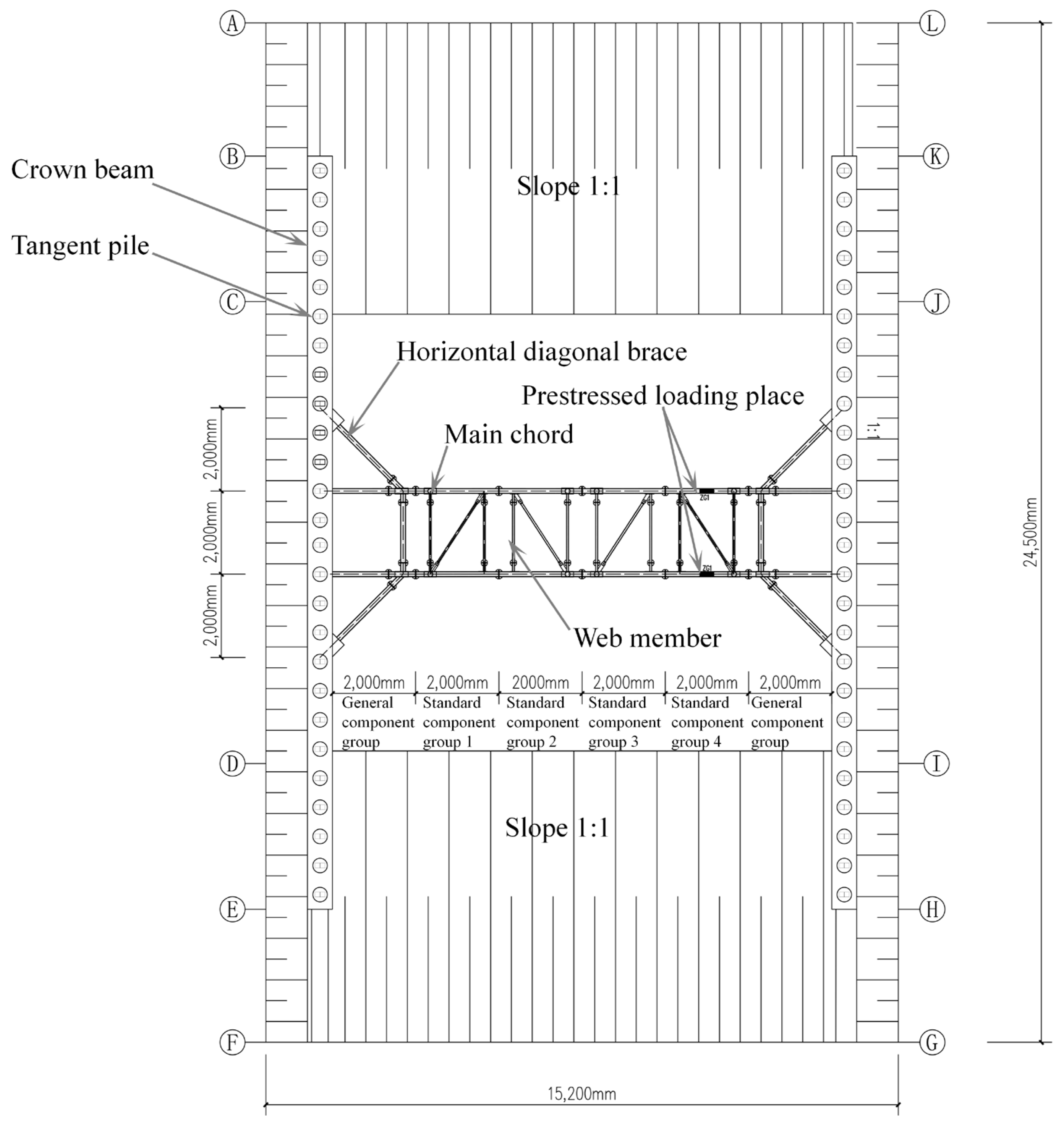
The test site is situated 8 m from an unoccupied parking lot and 30 m from the nearest existing structure, ensuring negligible surcharge effects on the excavation. Figure 1 illustrates the site layout, while Figure 2 presents the support system schematic.
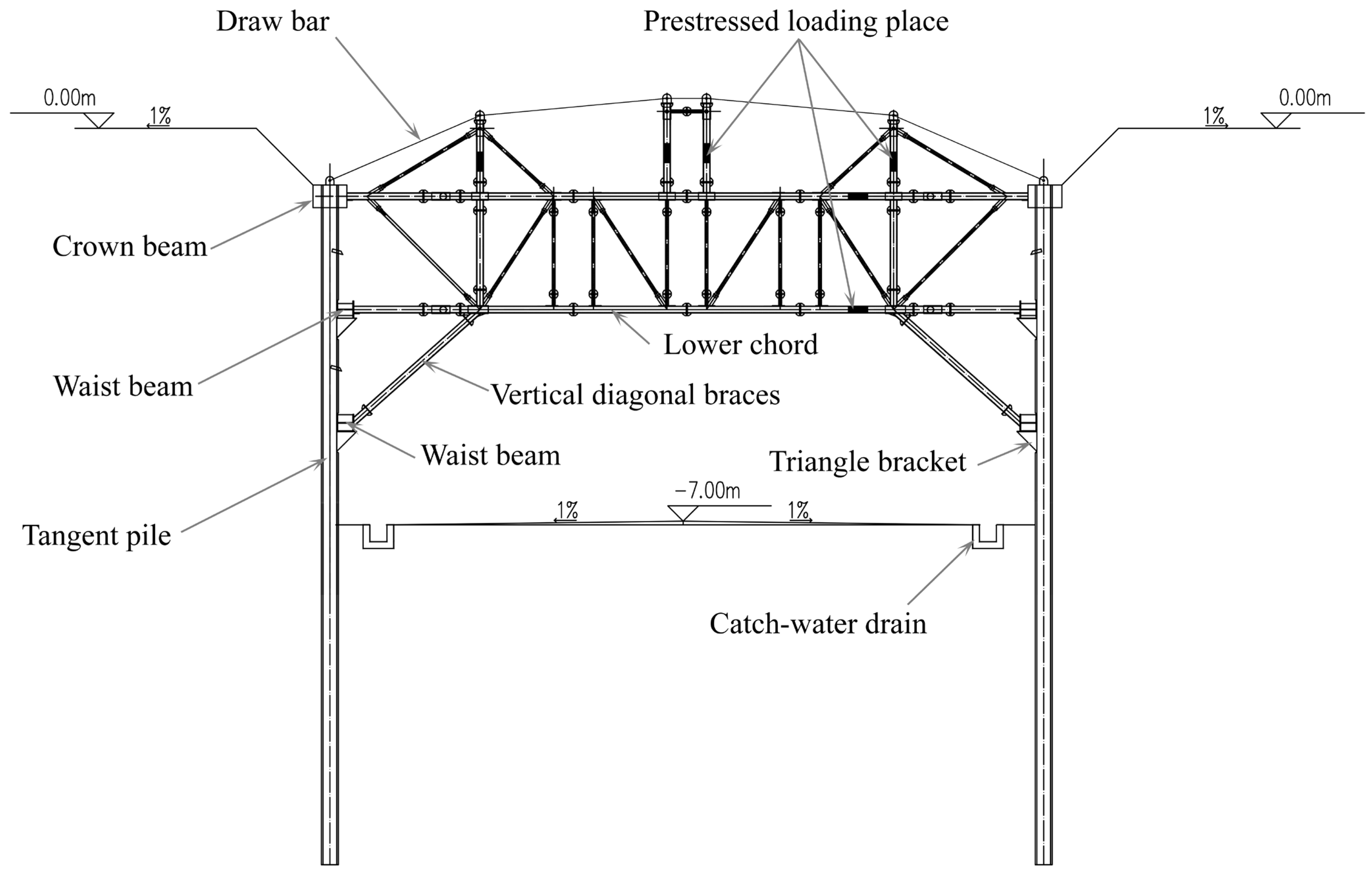
The system was installed transversely across the foundation pit. The modular truss units, with standardized dimensions of 2 m (length) × 2 m (width) × 2 m (height), were systematically arranged along the pit’s width direction. A horizontal diagonal brace with a support width of 2 m is arranged. The structural members, including four upper and lower chord members, horizontal diagonal braces, and vertical diagonal braces, were fabricated from 121 mm diameter steel tubes with a 6 mm wall thickness. The diameter of the connecting rod is 50 mm, and the wall thickness is 4 mm. The diameter of the steel tie rod is 30 mm. The materials are all Q235 steel. The support system is composed of four standard component groups, with a length of 2 m in the middle, and two general component groups, with a length of 2 m on both sides. In this field model experience, the size of the foundation pit is 24.5 m × 15.2 m, the excavation depth is 7 m, the width direction is a 1:1 slope of 1 m, and the other two sides are 1:1 slopes to the bottom of the pit. The supporting piles with a diameter of 0.35 m, a spacing of 0.7 m, and a length of 12 m are arranged along the length direction of the foundation pit. There is no supporting pile in the range of 3.5 m on both sides of the slope. Taking the ground as ±0 elevation, the upper chord support point is at −1 m, the lower chord support point is at −3 m elevation, and the oblique support point is at −5 m elevation. A 0.6 m × 0.4 m (width × height) concrete crown beam is arranged at −1 m elevation, and a HW300 × 300 × 10 × 15 wide-flange steel waist beam is arranged at −3 m and −5 m, respectively. The schematic diagram of the foundation pit support facade is shown in Figure 3.

2.1.2. The Force Transmission Path

Figure 3 demonstrates the fundamental distinction in load-transfer mechanisms between the novel spatial steel-truss bracing system and conventional horizontal supports. While traditional systems primarily resist lateral earth pressures, the proposed truss system incorporates diagonal braces that enable three-dimensional load redistribution through both horizontal and vertical force components. There will be a horizontal component force and a vertical component force at the connecting node. The vertical component force will cause the space truss to deform upward. On the one hand, it will cause the deformation of the retaining structure to increase. On the other hand, it is very unfavorable to the stability of the space truss. In order to eliminate this adverse effect, the new space steel joist internal support structure system lifts the tension steel draw bar of the movable support rod through the vertical prestressed device installed on the tower. The two ends of the steel draw bar are anchored at the top of the crown beam, and the vertical reaction force provided by the draw bar balances the vertical component of the inclined support, so as to achieve the purpose of deformation control and guaranteed stability. In the horizontal direction, the steel support is actively compressed by prestressed loading to enhance the deformation control effect of the foundation pit, and the support adjustment function of the whole support system is realized.

2.2. Experiment Procedure and Monitoring

Wu et al. [34] demonstrated that mono-symmetric structural configurations exhibit heightened sensitivity to varied loading conditions. To comprehensively capture the deformation and stress response of the support system under different construction phases, the experimental protocol was designed in strict compliance with actual construction sequences, incorporating established monitoring methodologies [25,26,35,36]. The implementation procedure comprised the following key stages:
  • Construct a support pile and a crown beam;
  • Excavate the site elevation to −4 m and install the internal support;
  • The first application of horizontal prestress (winding bar: 30 kN; lower chord: 60 kN);
  • Excavate the site elevation to −6 m, install the second waist beam, and use inclined support;
  • The second application of horizontal prestress (winding bar: 60 kN; lower chord: 120 kN);
  • The overall site elevation is excavated to −7 m;
  • Vertical prestressing (40 kN).
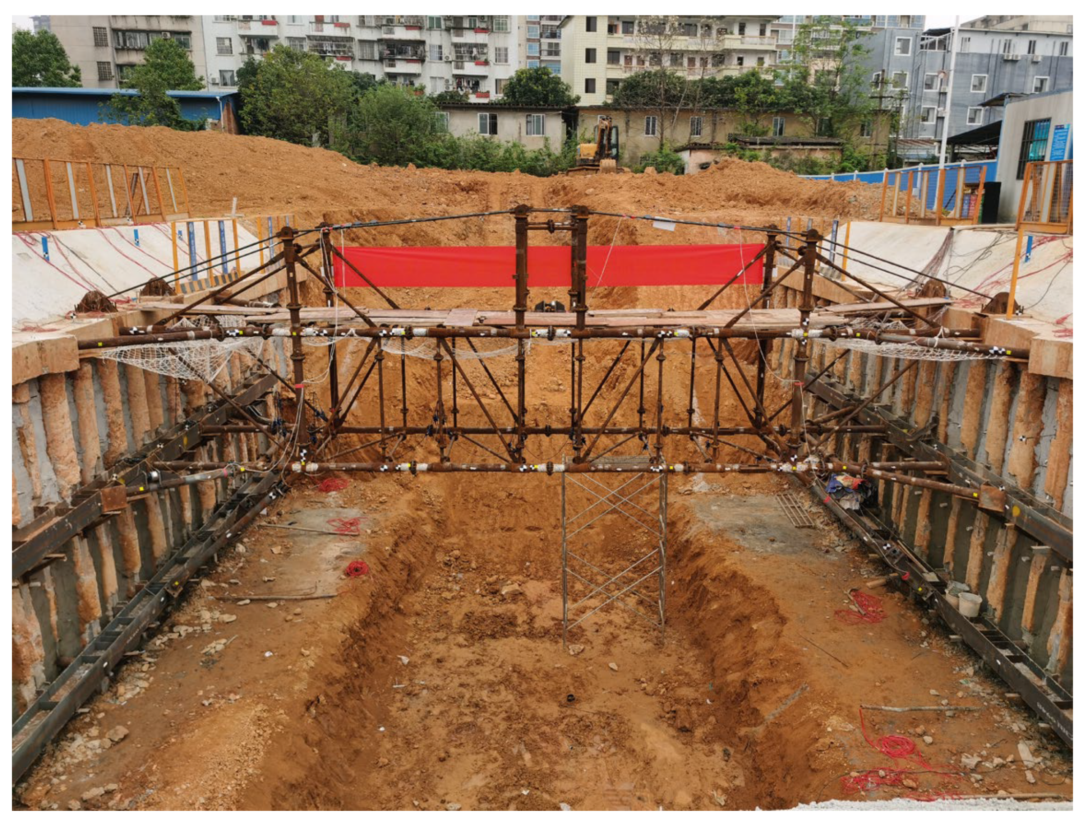
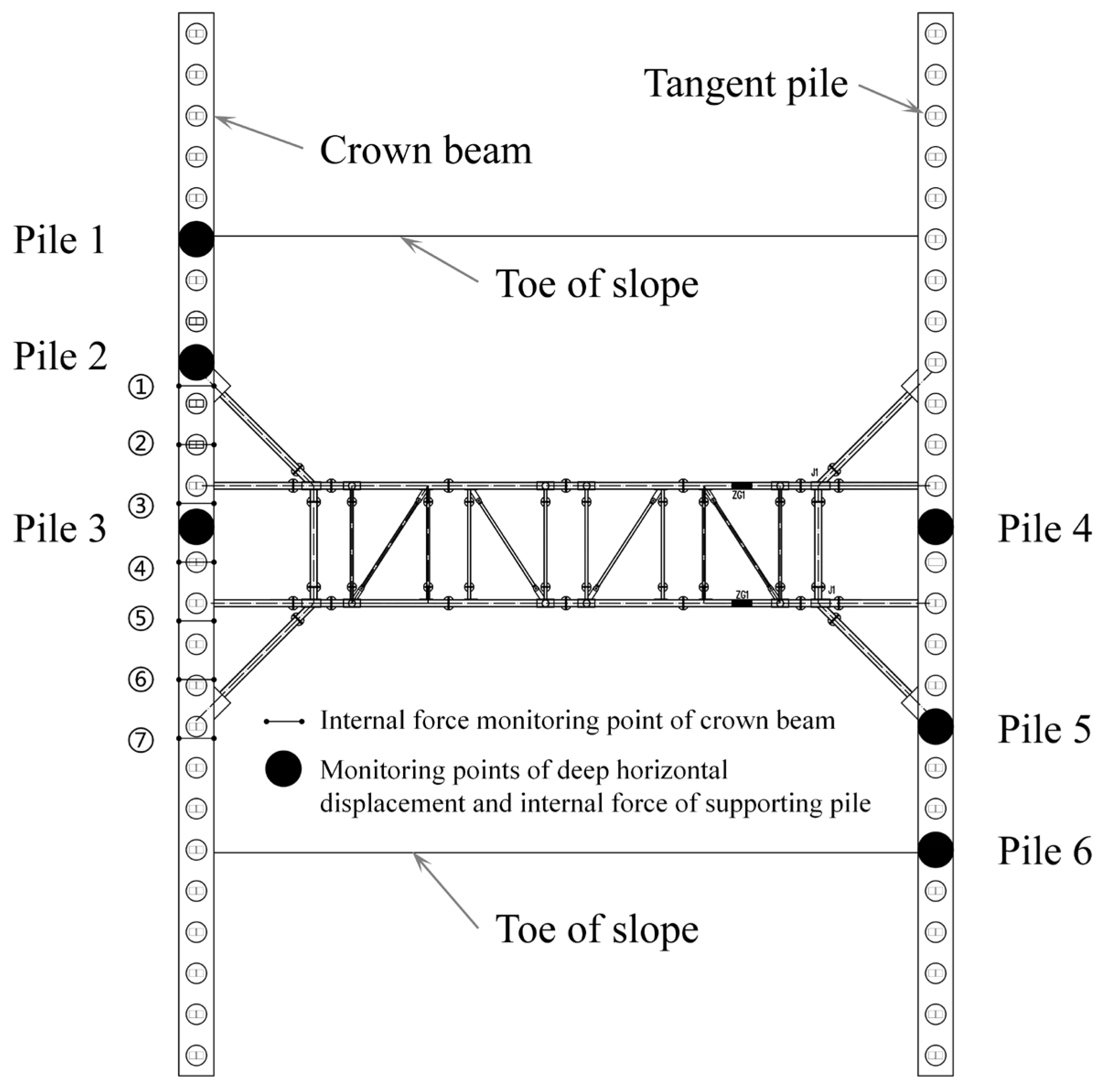
The completion diagram of the support installation in the foundation pit and the layout of the monitoring points of the supporting pile inclination and the left crown beam reinforcement meter are shown in Figure 4 and Figure 5.
Notably, during initial installation, gaps often exist between steel support members, which compromise deformation control. To eliminate these gaps and induce outward deformation of the retaining wall, prestress was applied to the horizontal members. In the first round of horizontal prestressing, 30 kN was applied to the upper chord and 60 kN to the lower chord using 20-ton hydraulic jacks. The applied load was monitored using digital pressure gauges mounted on a hydraulic pump and cross-checked using strain gauges installed on the steel members. Since the higher prestress in the lower chord could potentially cause force redistribution or loss in the upper chord, the loading sequence started with the lower chord, followed by the upper chord after stabilization. The loading sequence is illustrated in Figure 6.
After the diagonal braces were installed, a second round of horizontal prestress was applied to improve deformation control capability. During monitoring from the first prestress to the excavation level of −6 m, it was observed that the axial forces in the two upper chords were significantly uneven; one reached 35.26 kN while the other remained in tension only. This was attributed to load transfer effects between members during sequential tensioning. Therefore, in the second prestressing step, target forces were increased to 60 kN for the upper chords and 120 kN for the lower chords. Multiple cycles of incremental loading and adjustments were performed to balance axial forces across all members, ensuring stability and effective deformation control.
In practical applications, horizontal prestress is typically applied before excavation or dynamically adjusted during excavation to optimize performance. However, in this experimental study, to isolate and analyze the influence of vertical prestress on the system’s overall behavior, vertical prestress was intentionally applied after excavation was completed. The procedure involved tensioning the middle node of the vertical tie rod first, ensuring the member was taut, followed by adjusting both end nodes to reach the design value of 40 kN each. After completion, the measured tensile force in the steel rod reached approximately 90 kN. The vertical prestress setup is shown in Figure 7.

2.3. Derivation of Stiffness Calculation Formula

2.3.1. Derivation of Stiffness Formula of Non-Vertical Diagonal Brace

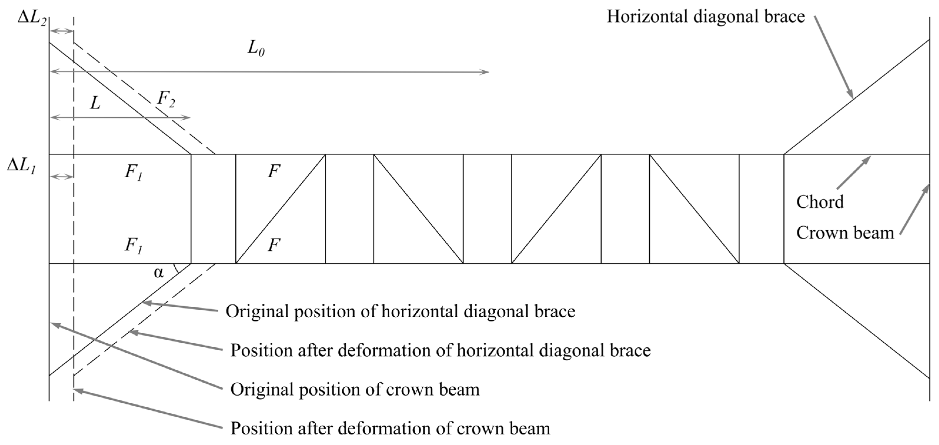
The calculation diagram of a non-vertical diagonal brace is shown in Figure 8.
Assuming that the force on the outer chord of the horizontal diagonal brace is F, the force acting on the chord and the horizontal diagonal brace within the horizontal diagonal brace range can be expressed as
F 1 = ε 1 F ,   F 2 = ε 2 F
The compression deformation of the chord of the horizontal diagonal brace can be expressed as
Δ L 1 = F 1 L E A = ε 1 F L E A
The compression deformation of the chord is not in the horizontal diagonal brace section:
Δ L 0 = F ( λ L 0 L ) E A
The horizontal stiffness coefficient K is
K = F Δ L = ( L E A + E h A h c o s α + λ L 0 L E A ) 1

2.3.2. Derivation of Stiffness Formula of Steel Truss with Vertical Diagonal Brace

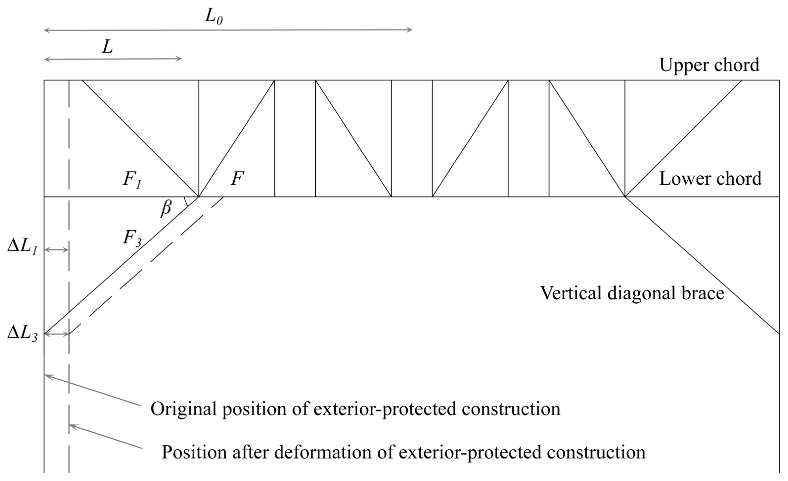
Figure 9 illustrates the computational model for analyzing the stiffness characteristics of vertical diagonal braces in the support system.
The calculation needs to consider the synergistic sharing effect of the vertical diagonal brace and the horizontal diagonal brace. It is still assumed that the force borne by the outer chord of the vertical diagonal brace and horizontal diagonal brace range is F; then, the force borne by the chord in the range of the horizontal diagonal brace and the force of the horizontal diagonal brace can be expressed as
F 1 = ε 1 F ,   F 2 = ε 2 F
The force of the vertical diagonal brace can be expressed as
F 3 = ε 3 F
The compression deformation of the vertical diagonal brace perpendicular to the direction of the crown beam can be expressed as
Δ L 3 = F 3 c o s β L E x A x c o s β = ε 3 F L E x A x
According to the principle of deformation coordination,
Δ L 1 = Δ L 2 = Δ L 3
According to the balance analysis of the force system, it can be seen that the F of the outer chord of the horizontal diagonal brace and vertical diagonal brace, the F1 of the chord in the range of the horizontal diagonal brace and vertical diagonal brace, the F2 of the horizontal diagonal brace, and the F3 of the vertical diagonal brace form a balance force system in the direction perpendicular to the crown beam; that is,
F = F 1 + F 2 c o s β + F 3 c o s β
When combining (5) and (9), we have
ε 1 = E A E A + E s A s c o s α + E x A x c o s β
ε 2 = E S A S E A + E s A s c o s α + E x A x c o s β
ε 3 = E X A X E A + E s A s c o s α + E x A x c o s β
The compression deformation of the horizontal and vertical diagonal brace section is
Δ L 1 = Δ L 2 = Δ L 3 = F L E A + E S A S c o s α + E x A x c o s β
The total compression is
Δ L = Δ L 1 + Δ L 0 = F L E A + E s A s c o s α + E x A x c o s β + F ( λ L 0 L ) E A
The horizontal stiffness coefficient K is
K = F Δ L = ( L E A + E s A s c o s α + E x A x c o s β + λ L 0 L E A ) 1

2.3.3. Rationality Analysis of Stiffness Formula

Based on the excavation methodologies and numerical modeling approaches established in previous studies [37,38,39,40], the authors determined that the actual failure mechanisms observed in geotechnical engineering practice exhibit strong agreement with computational simulations conducted using MIDAS GTS NX V2021 R1 finite element analysis software. This study employs MIDAS GTS NX for numerical modeling and performance evaluation.
Numerical simulations were performed to analyze axial force variations in structural members and support stiffness modifications during sequential installation of vertical diagonal braces under incremental loading conditions. Figure 10 and Figure 11 present the axial force distribution contours for the spatial steel truss support system in the deep excavation. It can be seen that when the vertical diagonal brace is not installed, the axial force of the main chord reaches 384.93 kN, while the axial force of the connecting rod is only about 2.57 kN. When the vertical diagonal brace is installed, the axial force of the lower chord increases to 509.66 kN, while the axial force of the connecting rod is only about 10.17 kN. The connecting rods demonstrate negligible contribution to lateral load-bearing capacity and may be omitted from stiffness computations. According to Hooke’s law, the finite element structural stiffness is calculated and compared with the calculation results of Formulas (4) and (15). The comparison results are shown in Table 1.
From the comparison of the calculation results in Table 1, it can be seen that the theoretical calculation is close to the finite element calculation results, and the theoretical calculation formula is reasonable. The installation of a vertical diagonal brace increases the stiffness of the lower chord support by 28.24%, the support points are dispersed downward, and the deformation of the support pile is effectively constrained by multiple support points.

3. Results and Analysis

3.1. Supporting Piles

3.1.1. Displacement

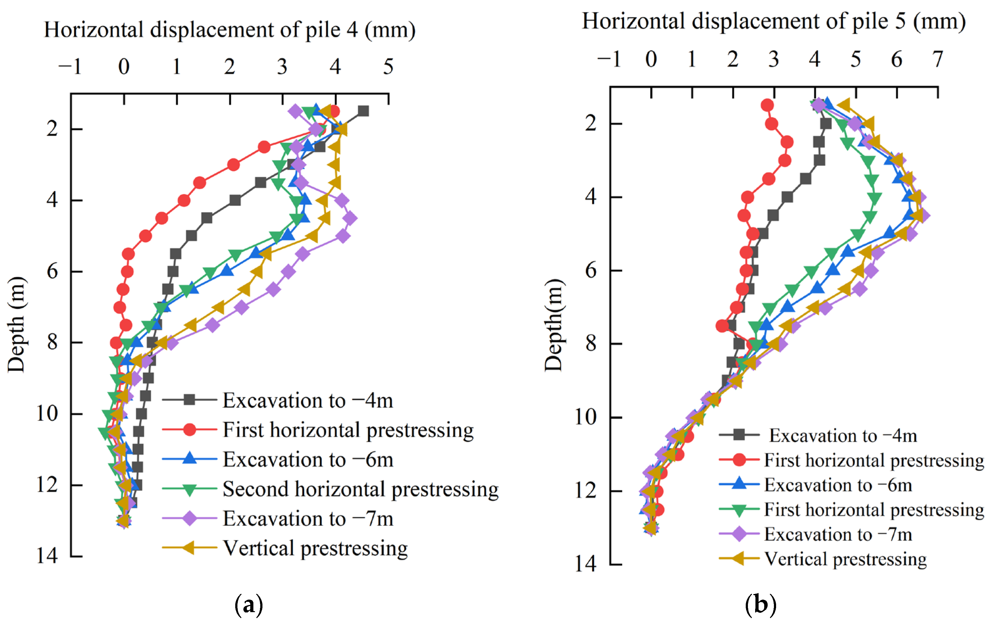
Figure 12a,b is the horizontal displacement diagram of the pile body of pile 4 and pile 5 in each working condition. It can be seen that when the foundation pit is excavated to −4 m, the deformation of the two piles is obviously cantilevered. The maximum horizontal displacement occurred at the pile head, with measured values of 4.53 mm for pile 4 and 4.09 mm for pile 5, demonstrating comparable magnitudes. Following the installation of the upper/lower chords, connecting rods, and the primary waist beam, the application of initial horizontal prestress resulted in a significant reduction in supporting pile displacements. As excavation progressed to −6 m, the pile head displacement exhibited minimal variation owing to internal support constraints, while the maximum horizontal displacement of pile 5 shifted to a depth of 3.5 m, reaching 6.32 mm. After installing the second waist beam and vertical diagonal brace, the horizontal prestress is applied again. The influence area and amplitude of the horizontal displacement reduction of pile 5 are more significant than those of pile 4, and the maximum influence point is at the support point of the vertical diagonal brace. When the foundation pit is excavated to −7 m, the horizontal displacement of the supporting pile is further increased, and the maximum horizontal displacement of pile 4 is also transferred to the position of 3.5 m from the top of the pile. Due to the horizontal component force of the steel tie rod, after vertical prestress is applied, the supporting pile will be pulled back into the pit, resulting in an increase in displacement within a certain range of the top of the pile; the displacement of the lower supporting pile decreases, and the maximum displacement of the supporting pile is less than the maximum deformation under the previous working condition.
The overall deformation law of the two monitoring piles tends to be consistent during the foundation pit test. At the −4 m excavation stage, the supporting pile begins to deform in a “convex drum shape”. Under both horizontal and vertical prestress application conditions, the prestressing forces effectively control supporting pile deformations. The deformation control effect is particularly pronounced in regions adjacent to vertical diagonal braces, where characteristic convex deformations are most significant. However, the local deformation laws of the two supporting piles are different. Pile 5 exhibits more consistent displacement patterns across various working conditions, with particularly pronounced convex drum-shaped deformation characteristics. The deformation law of pile 4 within 3 m from the top of the pile is more chaotic, and under the three prestress application conditions, the influence degree and main influence range of the two supporting piles are also different due to the joint connection of the steel support.
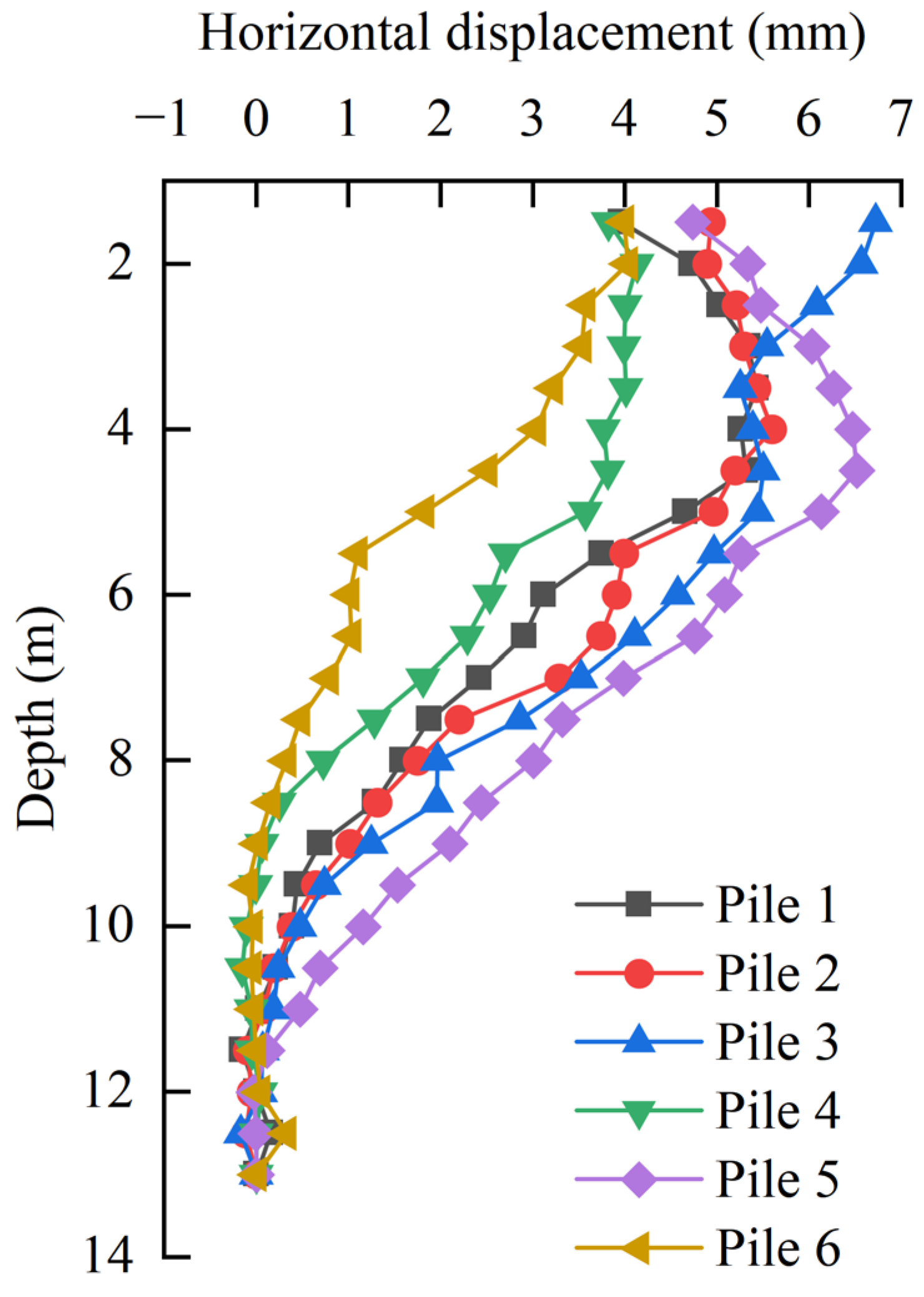
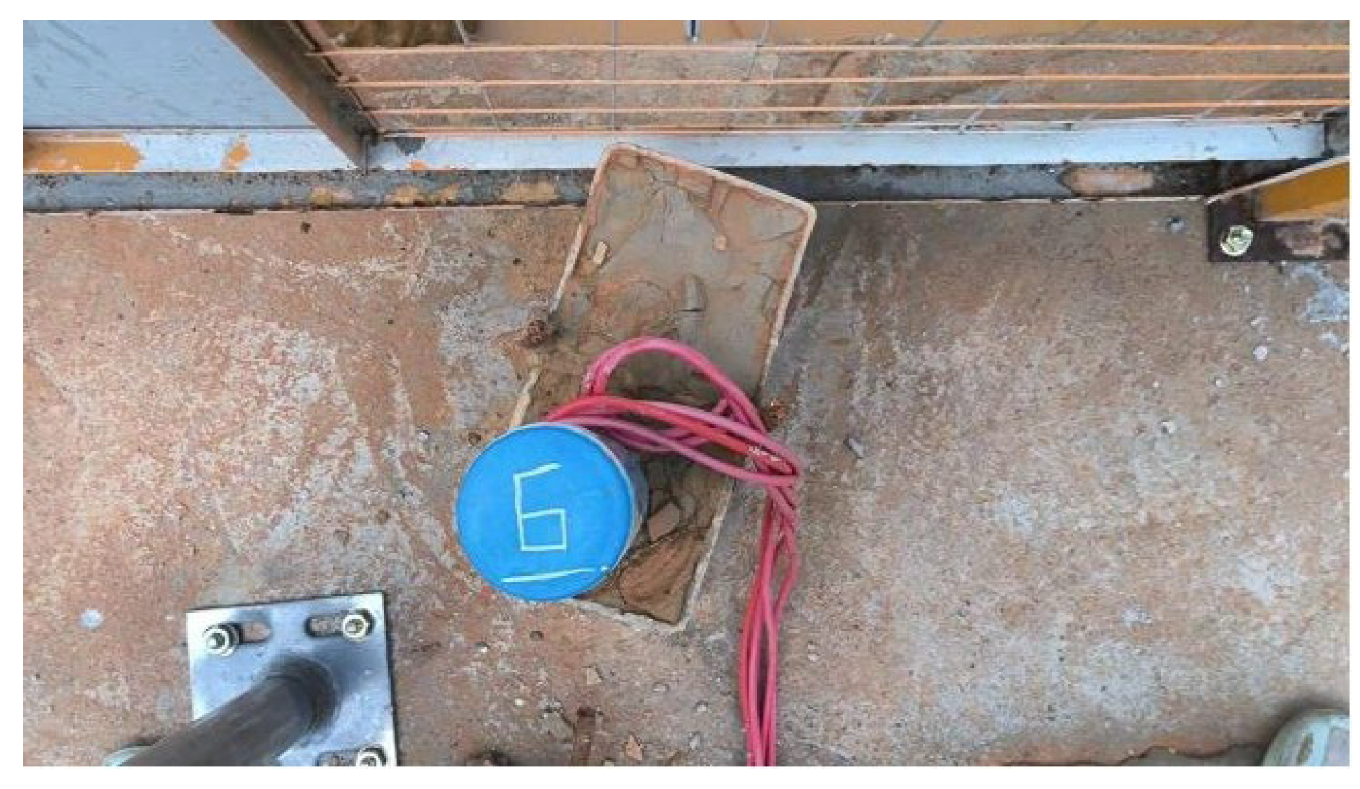
Figure 13 shows the horizontal displacement curves of six monitoring piles after the test was completed. The deformation shape maintains good consistency on the whole, and all are “convex drum shape” deformations, indicating that the new space steel joist internal support structure of a deep foundation pit passes through the crown beam and the waist beam, which better constrains the overall deformation of the support pile. Variations in deformation magnitudes and inflection points among supporting piles arise from multiple factors, including soil layer heterogeneity, pile construction quality, support connection integrity, and construction loads. Notably, pile 3 exhibits anomalous deformation within the upper 2 m zone, attributable to residual effects from prior single-pile bending tests that compromised its top-section stiffness. Pile 6 exhibited significantly smaller horizontal displacements than adjacent piles, with outward deformation occurring below the excavation base. The main reason is that during the construction of pile 6, after the square steel is inserted into the borehole, the square steel cannot be rotated due to the side wall friction, resulting in a large angle between the square steel and the width direction of the foundation pit, as shown in Figure 14, resulting in relatively abnormal measurement data.

3.1.2. Bending Moment

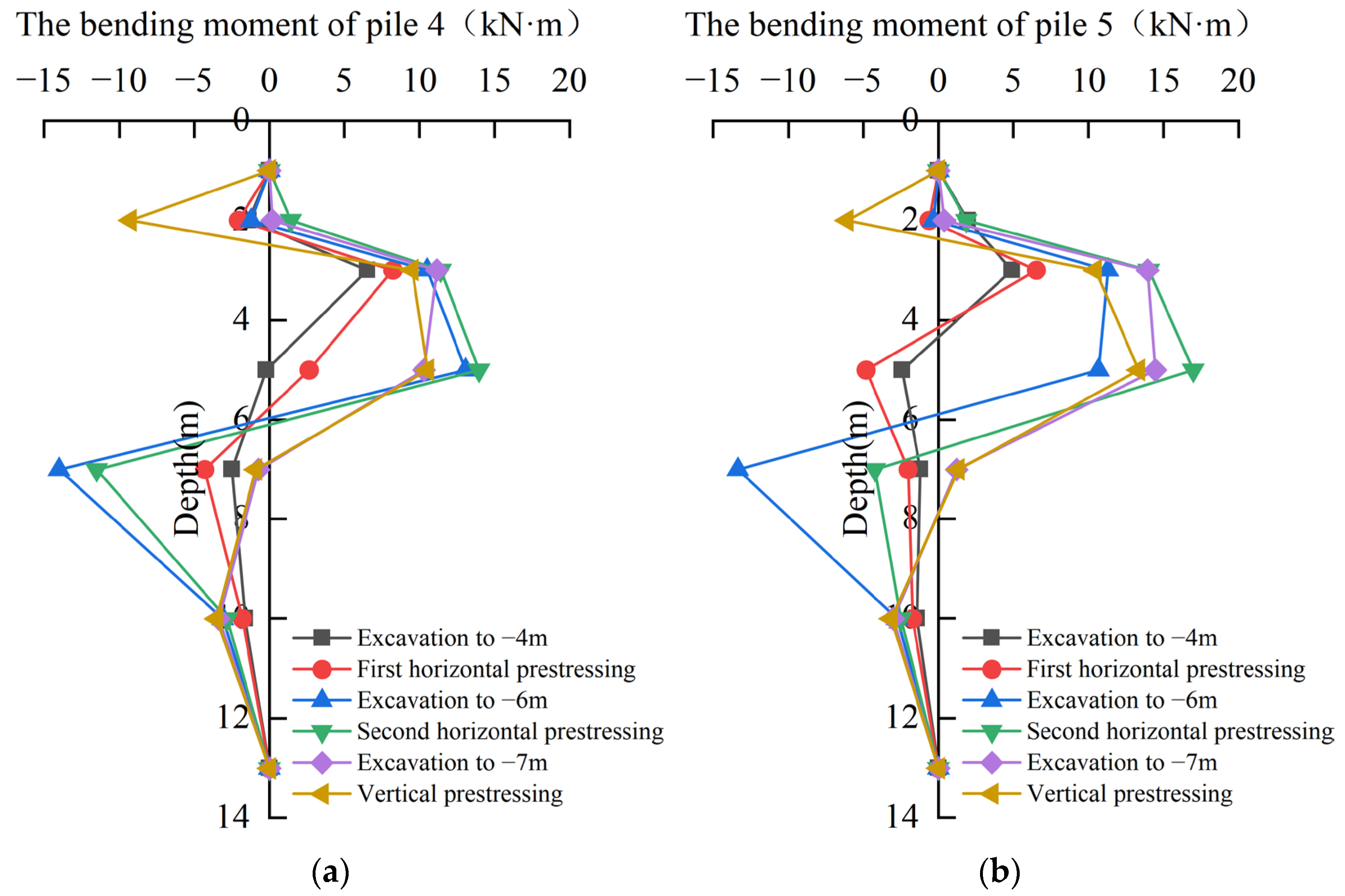
The bending moment sign convention for supporting piles is defined as follows: positive values indicate tensile stresses on the pit-facing side (inner surface), while negative values denote tensile stresses on the exterior side. As shown in Figure 15a,b, the bending moment distribution curve of pile 4 and pile 5 shows that when the foundation pit is excavated to −4 m, the second bending moment measuring point of pile 4 and the first and second measuring point bending moment values of pile 5 are all expressed as the inner side of the foundation pit. The first is due to the reading deviation of the steel bar meter itself due to the problem of cement slurry bonding and installation angle; the second is that when there is no support, under the action of the soil arching effect, the deformation of the supporting piles near the middle of the foundation pit is larger, whereas the deformation of the supporting piles on both sides near the toe of the slope is smaller. At this time, although the maximum horizontal displacement of piles 4 and 5 still occurs at the top, the supporting piles within a certain range below the top of the pile have actually developed into the inner side of the pit. At the excavation depth of −6 m, the deformation of the supporting pile in the new excavation range increases, the maximum positive and negative bending moment measurement values of the monitoring pile increase greatly, and the bending moment inflection point of the pile body develops downward. When the excavation is −4 m, the bending moment at the inclined support point is negative, and when the excavation is −6 m, the measuring point bends to the pit, and the bending moment measurement value develops into a positive value. After the second application of horizontal prestress, the bending moment at the second waist beam increases to a large extent. The comparative analysis of piles 4 and 5 reveals that horizontal prestress application increases axial forces in the internal support system, thereby elevating bending moments in the upper sections of the supporting piles. However, the increased axial force in the lower support piles reduces the soil resistance at the fixed end, leading to decreased bending moments in these pile sections. At the excavation depth of −7 m, the measured bending moment of the pile body in the range of the second waist beam and above is relatively small, while the bending moment of pile 4 at the −7 m measuring point is greatly reduced to close to 0; the bending moment of the pile 5 changes from positive to negative, and the bending moment of the two piles at −10 m increases slightly. This shows that with an increase in excavation depth, the bending moment of the pile body moves down, and the −7 m position is close to the inflection point. At this time, the maximum negative bending moment of the pile body is in the range of −7 m to −10 m. After applying vertical prestress, it can be seen that the pile top is obviously pulled at this time, and the bending moment of the supporting pile in the range above the first waist beam increases obviously, while the bending moment in the lower part decreases slightly.
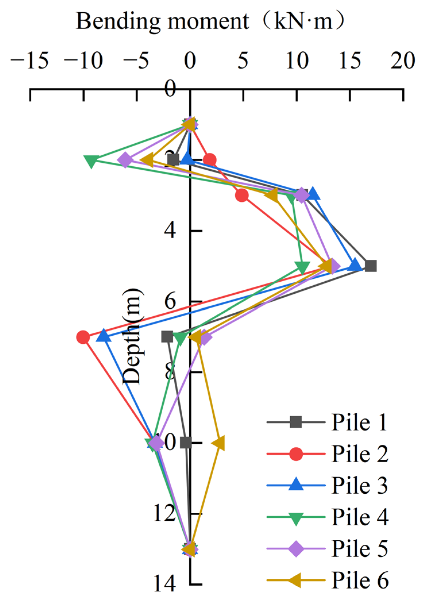
Figure 16 presents the bending moment distribution along the monitored piles under vertical prestress conditions. The six monitored piles exhibit consistent bending moment distribution patterns. As the depth increases, the positive bending moment in the supporting pile gradually increases. Near the excavation surface, due to the resistance of the soil, the positive bending moment of the supporting pile gradually decreases and develops downward into a negative bending moment. Due to the tension of the steel tie rod, the top of the supporting pile will produce a large negative bending moment. The bending moment values of the six monitoring piles at the position of −7 m are quite different, and the positive and negative values are also inconsistent. This shows that due to the influence of stratum differences, support constraints, and pile quality, the inflection points of different supporting piles in the same excavation depth are different. Combined with Figure 17, it can be found that the relative relationship between the bending moments and deformation values of the six monitoring piles is inconsistent. This is because the internal support has different deformation constraints on each supporting pile, resulting in different supporting piles. The corresponding relationship between force and deformation is different.

3.2. Crown Beam

3.2.1. Axial Force

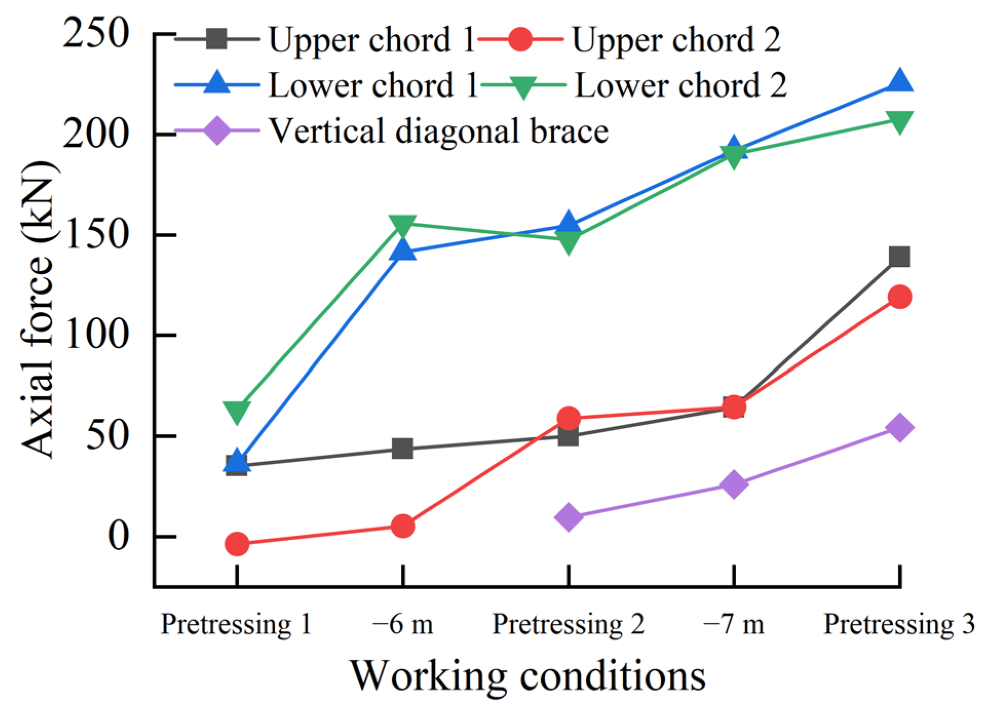
According to the test monitoring results, the development trend of the axial force of different support rods under different excavation conditions was analyzed. Given the consistent axial force trends observed in all four vertical diagonal braces, a representative member was selected for detailed analysis of the axial force variation patterns. The change curve of the axial force of each support rod under different working conditions is shown in Figure 17. When the horizontal prestress is applied for the first time, the prestress values of the two lower chords are slightly different, which is mainly due to the tension and compression effects on other supports during the loading process, resulting in prestress relaxation. By comparing the support axial forces of the upper and lower chords, it can be found that the support rod with a larger initial axial force has a significantly larger support axial force when the foundation pit is excavated to −6 m, which further illustrates the effect of eliminating the support gap by applying prestress to improve the deformation control effect. When the horizontal prestress is applied for the second time, through repeated cyclic loading and debugging, the support axial forces of the two upper chords and the two lower chords are basically the same, which ensures the force balance of each support bar, and the inclined support also bears the force prestress at this time, which is more favorable for support deformation control. Under the two working conditions of foundation pit excavation of −6 m and −7 m, the axial force growth of the lower chord support is obviously larger than that of the upper chord, which is mainly because the lower support has an obvious ‘barrier’ effect on the upper support. After applying vertical prestress, the increase in axial force of the upper chord is obviously greater than that of the lower chord. The axial forces increased by 74.54 kN and 54.45 kN in the upper chords, 33.47 kN and 17.41 kN in the lower chords, and 28.34 kN in the vertical diagonal braces. The increase in the axial force of the upper chord is due to the anchorage of the steel tie rod and the crown beam. The horizontal component of the steel tie rod is mainly borne by the upper chord. The increase in the axial force of the lower chord is mainly due to the increase in the axial force of the vertical diagonal brace caused by the vertical component of the steel tie rod. The vertical diagonal brace is connected to the lower chord, which leads to an increase in the total axial force of the lower chord. The increase in the axial force of the vertical diagonal brace further clarifies the effect of applying vertical prestress on the deformation control of the supporting pile.

3.2.2. Bending Moment

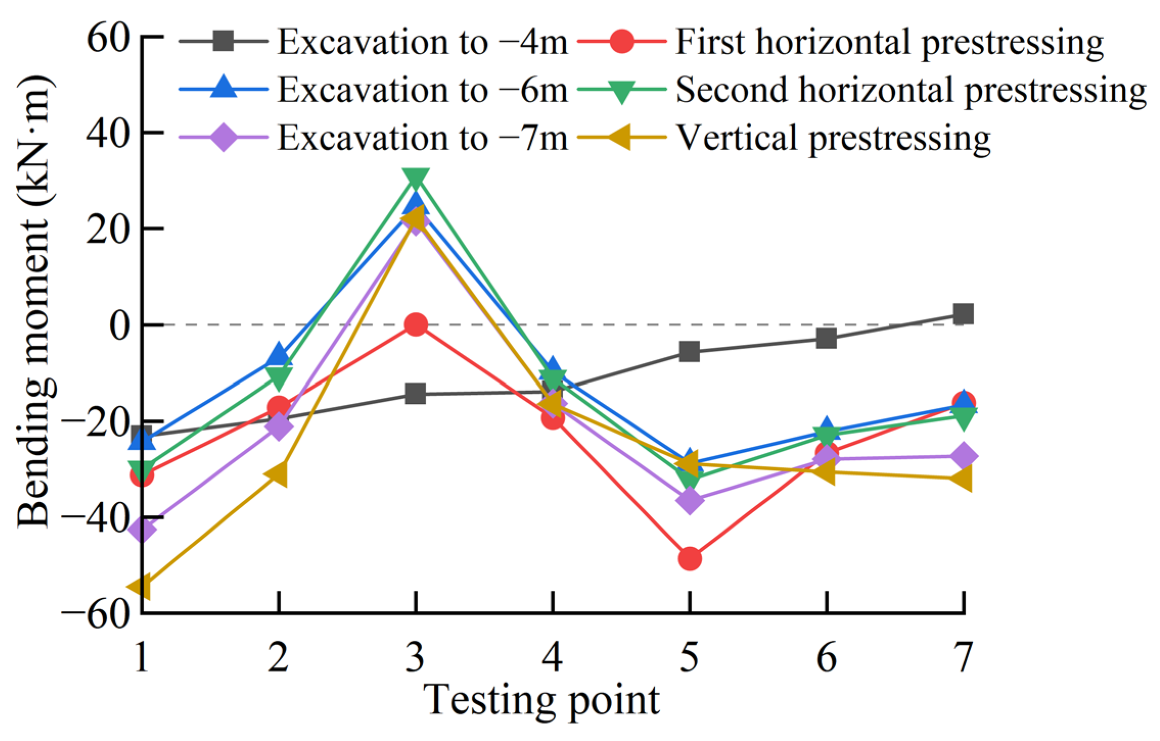
This paper stipulates that the tensile bending moment on the inner side of the crown beam pit is positive and the outer side is negative. Figure 18 effectively illustrates both the spatial distribution of bending moments along the crown beam and their temporal evolution during excavation. The calculated bending moments at each crown beam section reveal that measuring points 3 and 5 align with the support locations of upper chord 1 and upper chord 2, respectively. The variation of the bending moment measurement results of the crown beam at individual measuring points is promiscuous, but on the whole, it can still reflect the distribution law of the bending moment of the crown beam at each measuring point and the variation law during the excavation process. At the −4 m excavation stage, the bending moment of the crown beam gradually decreases from one end of the maximum negative bending moment to the other end, indicating that under the influence of soil layer difference and constraint difference at both ends of the crown beam, the side supporting pile has a unilateral tilt deformation. The supporting pile near measuring point 1 has the largest deformation in the pit, and the closer to measuring point 7, the smaller the deformation of the supporting pile. After the first horizontal prestress is applied, it can be seen that the bending moment state of the crown beam has changed greatly. The negative bending moment of measuring point 3 decreases, and the negative bending moment of measuring point 5 increases. This shows that the crown beam at measuring point 3 is subjected to tension and has a tendency to deform into the pit, while measuring point 5 is subjected to support compression. The increased compression on the pit-facing side of the crown beam correlates with heightened negative bending moments, consistent with the observed axial force variations in the support system under these loading conditions. Upper chord 1 is compressed, and upper chord 2 is pulled. At the −6 m excavation stage, the bending moment of the third measuring point becomes positive, and the negative bending moment of the other measuring points decreases. This shows that the active loading of prestress will increase the stress of the crown beam, and with the deformation of the foundation pit excavation, the internal force of the crown beam will be offset to a certain extent, which better reflects the active control of prestress. After the second application of horizontal prestress, the bending moment of each measuring point is smaller than that of the first time, and it can be seen that the bending moment of measuring point 3 is still positive, indicating that the application of prestress does not change the bending direction of the crown beam of the section. This phenomenon occurs because the effectiveness of prestress redistribution diminishes with increasing excavation-induced deformations, underscoring the critical importance of applying prestress during initial loading stages. After the deformation of the foundation pit, the prestress loading is carried out, and the deformation control effect of the foundation pit will be greatly reduced. At the −7 m excavation stage, the bending moment of the crown beam changes little, which is mainly because as the excavation depth increases, the waist beam gradually plays a more coordinating role. When the vertical prestress is applied, the vertical prestress will have a more obvious influence on the internal force of the crown beam, and the bending moment of the crown beam will increase as a whole because the anchor seat of the tie rod is directly anchored in the crown beam.

3.3. Comparative Analysis of Numerical Simulation Results and Measured Results

3.3.1. Modeling Methodology

The model was established by Midas GTS NX V2021 R1 software [41]. When selecting the model parameters, in addition to defining the two basic parameters of friction angle and cohesion according to the geotechnical test, the three modulus parameters of the secant modulus, tangent modulus, and unloading modulus should be defined [42,43,44]. All geotechnical materials were modeled using an isotropic modified Mohr–Coulomb constitutive model. The material parameters for the supporting structures and geotechnical layers are summarized in Table 2 and Table 3.
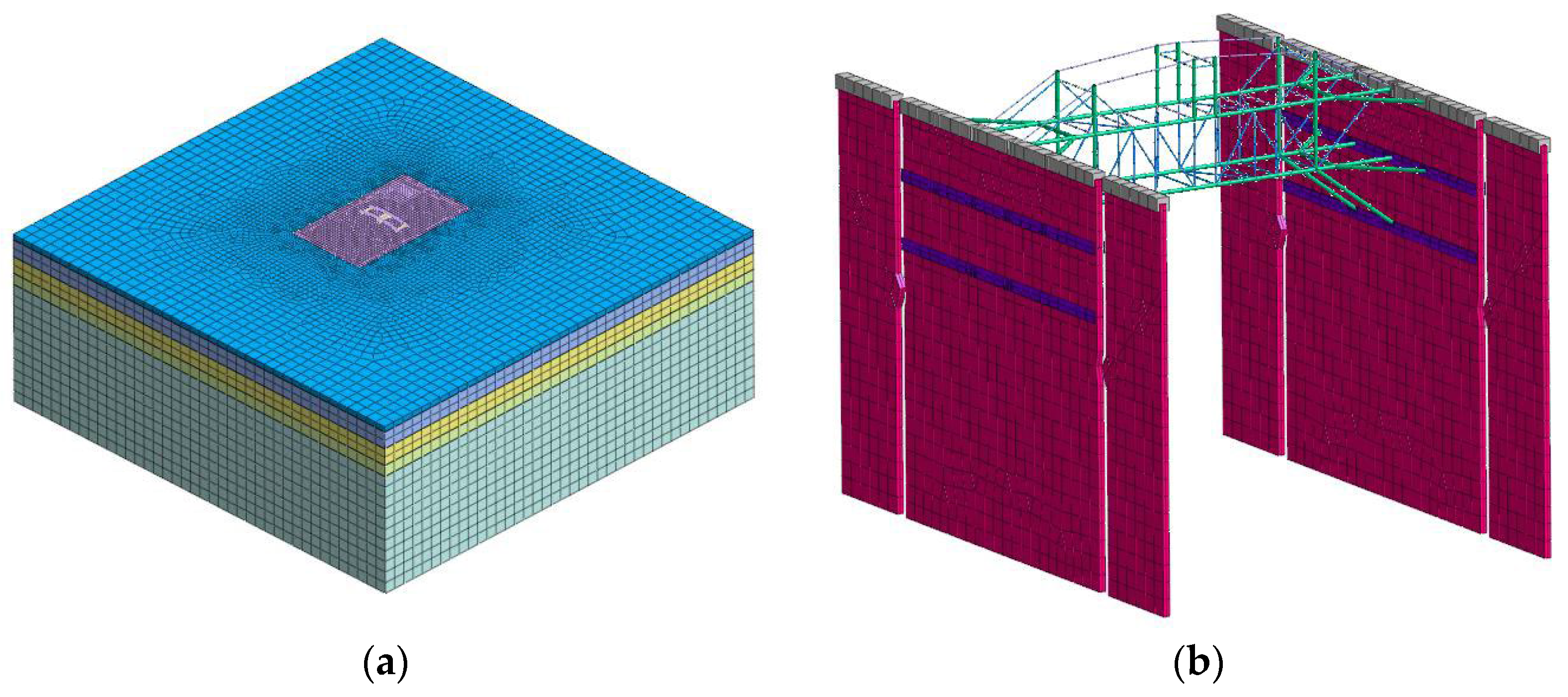
To accurately simulate the soil arching effect caused by the slopes on both sides, this model uses a three-dimensional model. The size of the model is 80 m × 80 m × 30 m (length × width × height) to reduce the size effect. The joint connection is assumed to be a rigid connection, and the actual situation of the test is simulated by breaking the diaphragm wall and the crown beam at the bottom of the slope. After cutting the geometric entity, the grid is divided from the boundary grid size of 2 m to the foundation pit grid size of 0.5 m according to the linear gradient, and the total grid number of the model is 154,574. Figure 19 presents the three-dimensional numerical model of the excavation and supporting structure system.
In Midas software, the prestress needs to be activated at the same time as the support to achieve the pre-addition effect. For the first time, only one horizontal prestress can be added. According to the actual construction sequence, the model is divided into nine construction stages: (1) initial stress balance; (2) activate the supporting pile; (3) excavate to −1 m, activate the crown beam; (4) excavation to −4 m; (5) activate the first waist beam, space truss internal support, and horizontal prestress (upper chord: 60 kN; lower chord: 120 kN); (6) excavation to −6 m; (7) activate the second waist beam, diagonal support; (8) excavation to −7 m; (9) activate the tower and tie rod and apply vertical prestress (90 kN).

3.3.2. Comparative Analysis of Horizontal Displacement

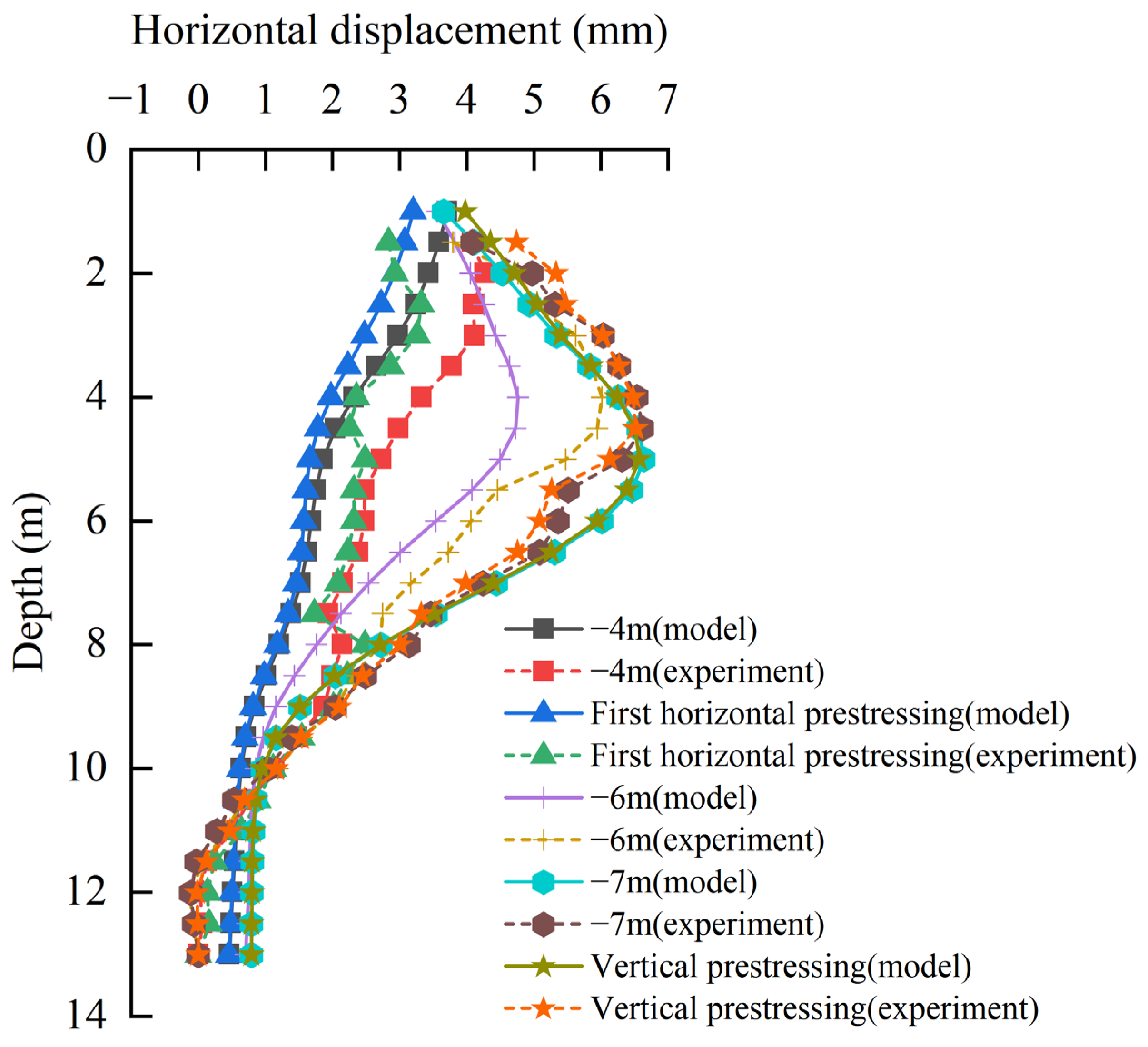
The comparison between the numerical calculation of the horizontal displacement of pile 5 and the test monitoring results is shown in Figure 20. During the whole test process, the numerical calculation of pile 5 is basically consistent with the development law of pile body deformation measured in the field. At the −4 m excavation stage, the maximum horizontal displacement of the numerical simulation and the test pile body occurs at the top of the pile due to the constraint effect of no support, and the numerical calculation results are slightly smaller than the measured values. After the first horizontal prestress is applied, due to the prestress effect, the support has a back-to-top effect on the supporting pile, and the deformation of the supporting pile is reduced. The numerical results show smaller rebound displacements than the field measurements, as evidenced in Figure 20. This is mainly due to the good coupling of the nodes in the numerical simulation. The range of action of the support on the supporting pile is large and uniform. The effect of prestress in the test is more concentrated on the supporting pile near the support point, resulting in a measured back-to-top displacement that is greater than the numerical calculation. When the foundation pit continues to be excavated down to −6 m and −7 m, the deformation of the supporting pile increases to a large extent. Due to the constraint of the steel support, the displacement of the pile head does not change much, and the deformation of the supporting pile in the middle of the excavation increases greatly, which makes the supporting pile deform in a “convex drum shape”. After applying vertical prestress, the deformation law of the numerical calculation of the supporting pile is consistent with the measured results. The supporting piles exhibit increased horizontal displacements within the upper 3.5 m zone, while reduced deformations occur below this depth threshold.
The maximum horizontal displacement and displacement points of the supporting pile under each excavation condition are extracted from the experimental monitoring data and the numerical calculation results. The comparative results are presented in Table 4. The numerical simulations yield maximum horizontal displacements and their locations, which show close agreement with field measurements across all working conditions. Combined with the comparison results of the pile shape of the supporting pile in the figure, the average error of the reference [5,14,45,46] is about 15%, and the displacement is small. In general, it can be considered that the model has a high fitting degree in simulating the deformation development law of the supporting pile under each working condition of the foundation pit excavation in this experiment, which can reflect the deformation law of the supporting pile during the excavation of the foundation pit. After applying vertical prestress, the horizontal displacement numerical calculation results of six monitoring piles are compared with the test monitoring results, as shown in Figure 21.
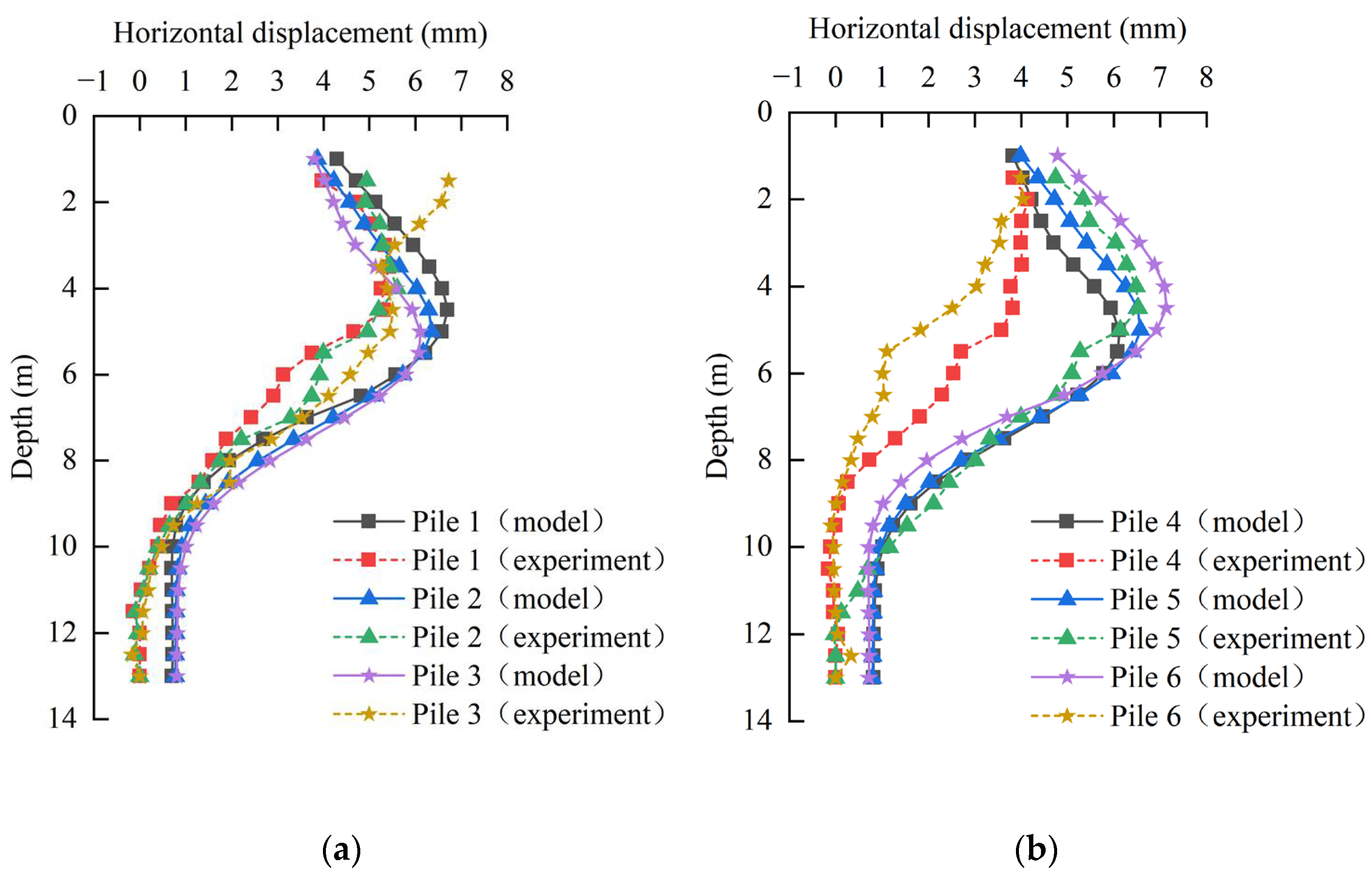
Figure 21a,b demonstrate close agreement between numerically simulated and measured deformation patterns for all six instrumented piles under vertical prestress conditions. Except that the measured data of plie 3 and pile 6 are greatly different from the other four supporting piles due to the previous test and construction problems, the other four piles show typical “convex drum shape” deformation, but it can be clearly seen that the numerical fitting degree of the four piles is different, and the numerical calculation results are generally larger than the measured results. The numerical results demonstrate consistent deformation characteristics between left-side and right-side supporting piles. The deformation of the supporting pile at the main chord position (pile 3 and pile 4) is the smallest, the deformation of the supporting pile at the foot of the slope (pile 1 and pile 6) is the largest, and the deformation of the supporting pile at the horizontal diagonal brace (pile 2 and pile 5) is between the two. In summary, the farther away from the main chord position, the greater the deformation of the supporting pile. This shows that in the numerical calculation, the closer to the main chord, the greater the deformation control effect of the support, and in the measured results, the deformation of the supporting pile does not strictly show this law.

3.3.3. Comparative Analysis of Bending Moment

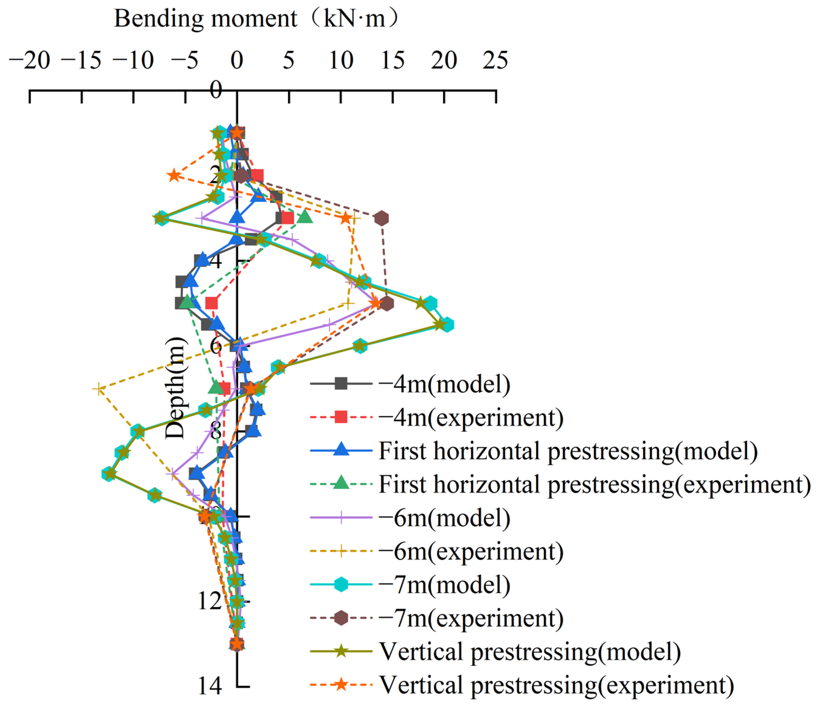
Figure 22 compares the numerically simulated and experimentally measured bending moment distributions along pile 5. Throughout the excavation process, the numerical simulations and field measurements demonstrate consistent bending moment distribution patterns along pile 5. As excavation progresses, both maximum positive and negative bending moments in the supporting piles exhibit progressive amplification, with their critical locations migrating downward along the pile shaft. The second inflection point of the pile body is concentrated at the excavation surface of the foundation pit. The difference between the numerical calculation results and the measured results is in the range above the lower chord. After the excavation of the foundation pit to –6 m, the first turning point of the pile bending moment in the numerical calculation is concentrated at the lower chord position, while the bending moment turning point in the test is within the range of the upper chord to the lower chord, forming a significant difference.
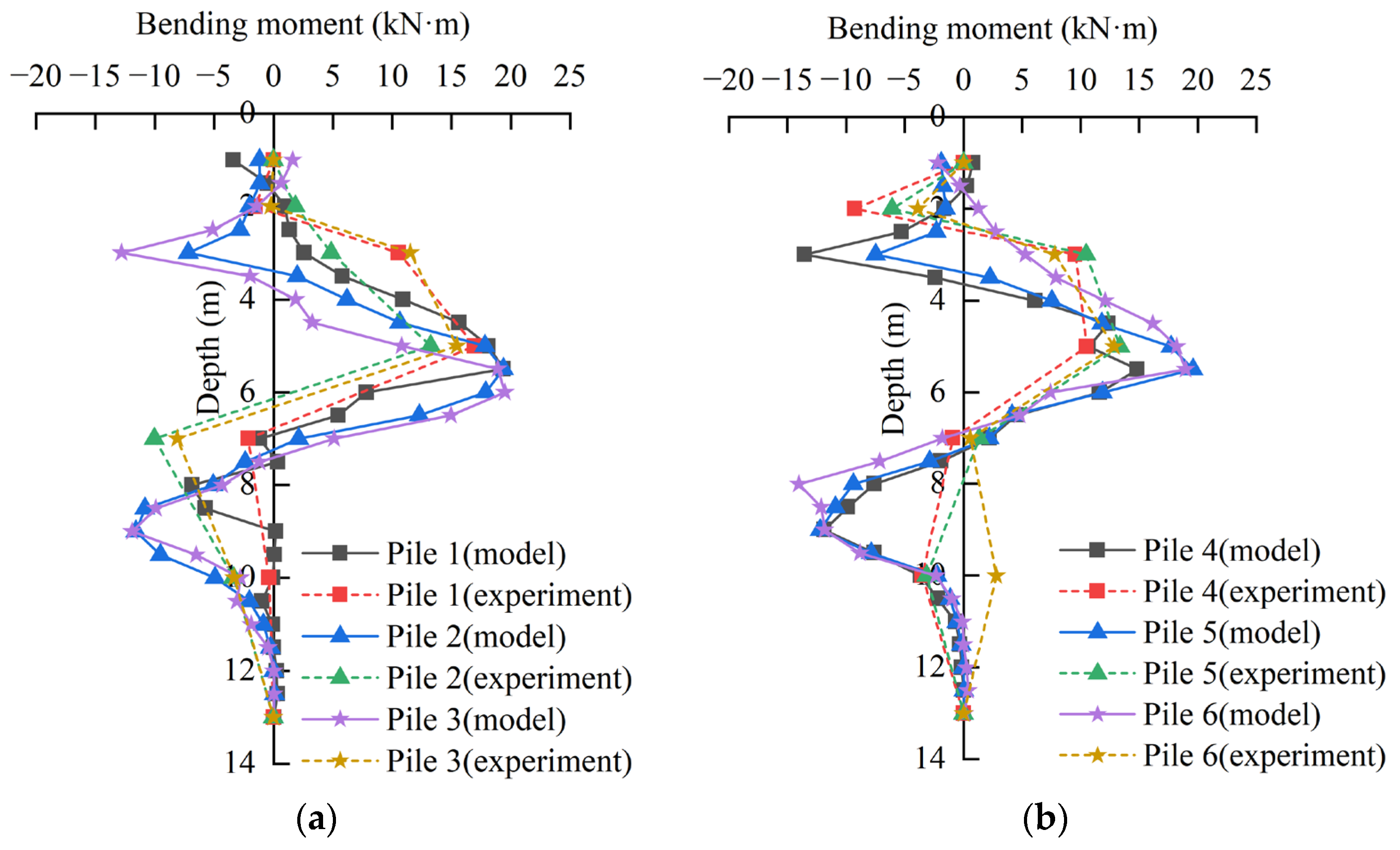
It can be seen from Figure 23a,b that the numerical calculation results of the bending moment of the six monitoring piles after the application of vertical prestress are compared with the experimental monitoring results. Following vertical prestress application, the numerical bending moment results for all six supporting piles align with the deformation trends observed in the two instrumented piles during field testing. At the −4 m excavation stage, the supporting piles begin to deform in a “convex drum shape”. In the two horizontal prestress and vertical prestress application conditions, the overall fitting of the measured results is better. Due to the tension of the steel tie rod, the supporting piles are deformed in the pit, and the supporting piles above the first waist beam produce a large positive bending moment. Due to the excavation of the soil, the supporting pile gradually bulges into the pit, and the positive bending moment gradually increases. Subsequently, the positive bending moments attenuate progressively due to basal soil resistance, transitioning into negative bending moments with increasing depth. The bending moment value of the numerical calculation is slightly larger than the measured results on the whole, which is consistent with the relationship between the horizontal displacement of the two supporting piles. The numerical results clearly indicate an inflection point concentration near the −7 m elevation, with the extreme negative bending moment occurring at −9 m below the excavation base. This validates the earlier interpretation that reduced bending moments at the −7 m excavation level result from the downward migration of the inflection point. It can be seen that the calculated inflection point locations of the right supporting pile are closer to the measured results than those of the left side.

3.3.4. Comparative Analysis of Steel Support Axial Force

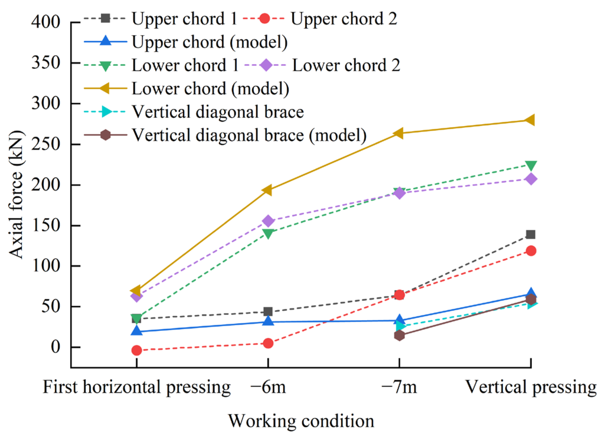
In the numerical calculation, the axial forces of the two upper chords, two lower chords, and the four diagonal braces are very close. Only one diagonal brace in the left front is selected. Figure 24 presents the comparison between numerical and experimental axial force measurements in the support members across different excavation stages.
The variation law of the axial force of each support rod maintains consistency. After the first horizontal prestress is applied, the support has a large initial axial force. Progressive excavation depth correlates with increasing axial forces in both upper and lower chords, with the lower chords exhibiting a higher rate of force accumulation. The application of vertical prestress induces substantial axial force increments in both the upper chord and vertical diagonal braces, whereas the lower chord experiences minimal force variations. The numerical value of the vertical diagonal brace axial force is not much different, but there is a certain gap between the numerical calculation results of the upper chord and the lower chord and the measured results. The numerical calculation results of the support axial force of the upper chord are always smaller than the measured results during the whole excavation process. In the numerical calculation, the axial force of the upper chord is basically unchanged under the excavation conditions of −6 m and −7 m, while the calculation results of the lower chord are always larger than the measured results.
After applying vertical prestress, the axial force of the upper chord increased by 74.54 kN and 54.45 kN, respectively, the axial force of the lower chord increased by 33.47 kN and 17.41 kN, respectively, and the axial force of the vertical diagonal brace increased by 28.34 kN. However, the axial force of the upper chord increased by only 32.77 kN, the axial force of the lower chord increased by 34.28 kN, and the axial force of the vertical diagonal brace increased by 44.19 kN. It can be found that the axial force difference of the upper chord is the largest, which indicates that after the vertical prestress is applied in the test, the supporting piles are only connected with the crown beam and the waist beam. The supporting piles on both sides of the anchor seat of the pull rod can hardly share the horizontal component force of the steel pull rod, and the horizontal component force of the steel pull rod almost acts on the upper chord. In order to simplify the modeling steps and reduce the amount of model calculation, the supporting pile is equivalent to the diaphragm wall. The integrity of the diaphragm wall is good. After the steel rod is tensioned, the load transfer performance of the diaphragm wall is good. The diaphragm wall can share a large part of the horizontal component force, so that the axial force of the upper chord is small. The variation of the axial force of the chord and the vertical diagonal brace under the numerical calculation is close to the measured change, which shows that the model is reasonable in terms of calculating the vertical force transmission mechanism of the new space steel joist internal support structure system of a deep foundation pit.
Discrepancies between numerical simulations and field measurements primarily stem from three factors: (1) there are some differences between the numerical model and the actual soil layer parameters and thickness; (2) in the process of supporting construction, the node connection cannot be fully coupled, the barrier effect is weakened, the difference of node connection is large, and the numerical model node is fully coupled; (3) due to the limitation of the numerical software, the prestress can only be applied once after the horizontal support is activated, which is different from the actual working condition.

3.3.5. Future Prospects

It is worth noting that the numerical model adopted in this study involves certain simplifications regarding joint behavior and soil constitutive properties. Specifically, all joints within the internal support structure were assumed to be fully rigid without slippage, and the soil was modeled using the Mohr–Coulomb elastic–plastic model, which does not fully capture strain-hardening, stress-path dependency, or time-dependent behaviors commonly observed in soft or structured soils [47].
These simplifications were primarily made to ensure computational stability and to focus on capturing the overall deformation trends and internal force distributions under varying excavation and prestress conditions [33]. While the modeling results show good agreement with the measured data in terms of deformation patterns and axial force development, the neglect of joint flexibility and advanced soil behaviors may limit the accuracy of the absolute values predicted by the model.
In future studies, the use of refined joint models that allow partial slippage, as well as advanced soil models, such as the Hardening Soil Model or Modified Cam-Clay model, should be considered to improve predictive accuracy and better reflect realistic construction and loading conditions.

3.4. Control Mechanism of Vertical Prestress

3.4.1. Influence on Support Characteristics

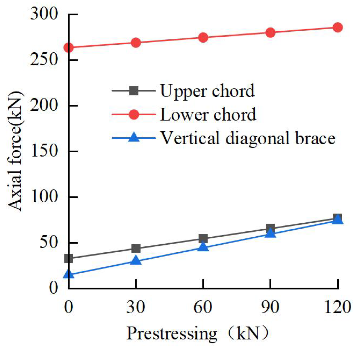
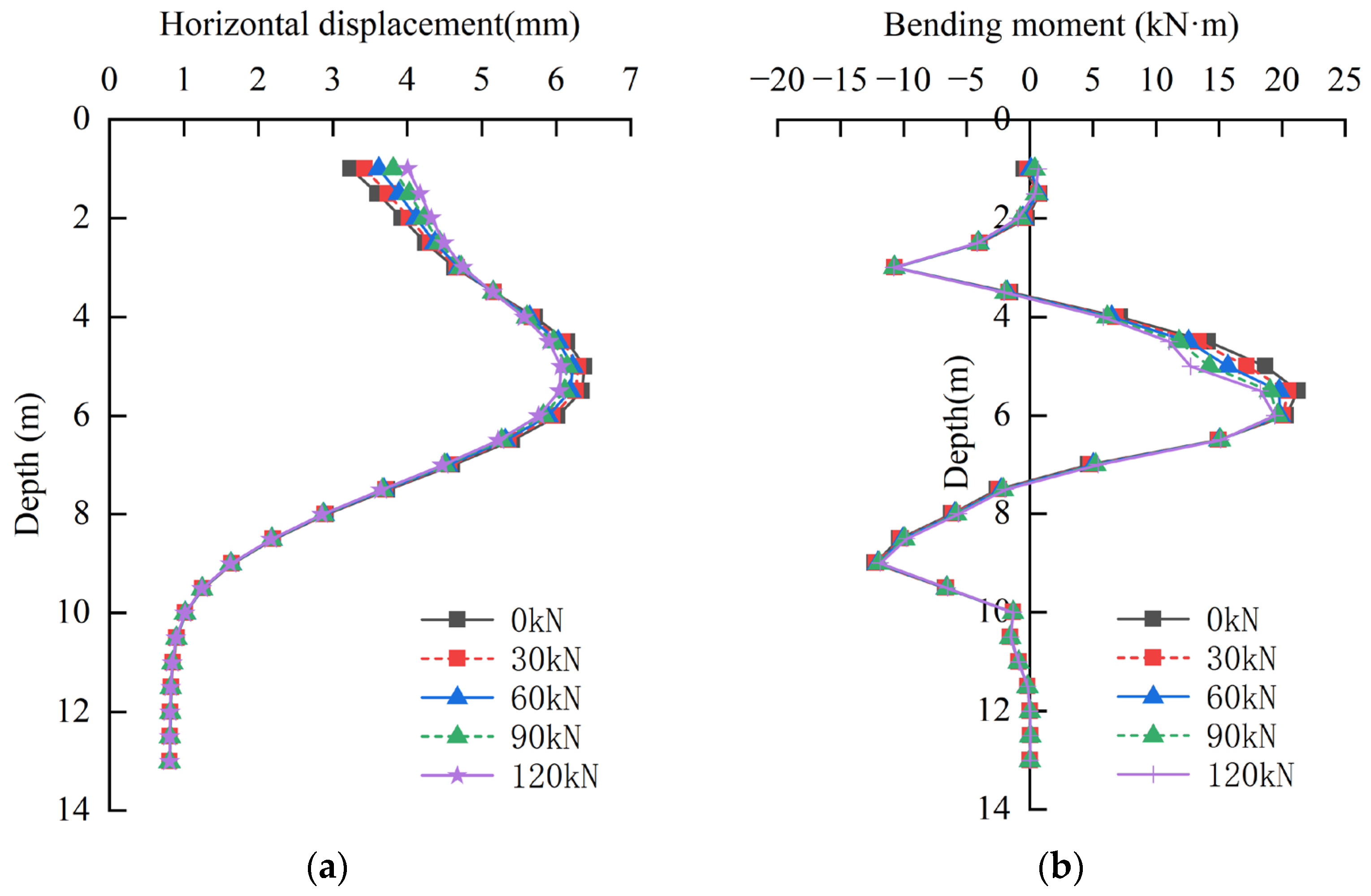
To investigate the influence of different vertical prestress magnitudes (30 kN, 60 kN, 90 kN, and 120 kN) on structural behavior, controlled prestress loading was applied to analyze the resulting variations in support system displacements, axial forces, pile deformations, and bending moments.
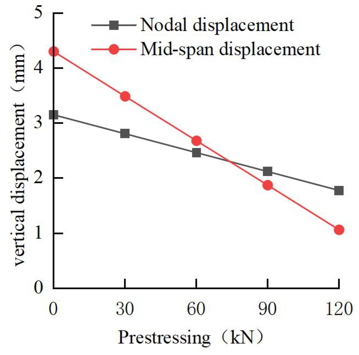
The following figures (Figure 25 and Figure 26) show the change curves of support displacement and support axial force under different prestresses, respectively. With an increase in the vertical prestress value, the mid-span displacement and node displacement of the support decrease, and the mid-span displacement decreases more obviously. The prestress value increases from 0 to 120 kN, the mid-span displacement decreases by 3.24 mm, and the node displacement decreases by 1.37 mm. The axial forces of the upper chord, the lower chord, and the inclined support all increased to varying degrees. The prestress value increased from 0 to 120 kN, and the axial forces of the upper chord, the lower chord, and the vertical diagonal brace increased by 43.97 kN, 21.97 kN, and 59.11 kN, respectively. The increase in the axial force of the upper chord is caused by the vertical component force generated by the tension of the steel tie rod, while the increase in the axial force of the lower chord and the vertical diagonal brace is due to the vertical component force after the tension of the steel tie rod being transmitted to the vertical diagonal brace through the tower and the vertical connecting rod, with the vertical diagonal brace being compressed downward, so that the bending deformation of the support is reduced and the axial force is increased.

3.4.2. Influence on Pile Displacement and Bending Moment

The horizontal displacement and bending moment change curve of pile 3 under different prestress is shown in Figure 27a,b. Increasing vertical prestress levels elevates the horizontal components in steel tie rods, consequently augmenting pile head displacements. Due to the increase in prestress, the bending deformation of the support decreases, and the axial force of the lower chord and the vertical diagonal brace increases, so the support plays a role in pushing back the support pile, and the maximum horizontal displacement of the support pile decreases. When the prestress value increases from 0 to 120 kN, the displacement of the pile top increases by 0.766 mm, and the maximum horizontal displacement of the pile body decreases by 0.311 mm. The displacement increment of the pile top caused by vertical prestress is greater than the maximum displacement reduction of the pile body, so it is not appropriate to apply excessive vertical prestress. Due to the increase in the axial force of the lower chord and the vertical diagonal brace, the maximum displacement of the supporting pile decreases, and the maximum positive bending moment of the supporting pile also decreases with the increase in the prestress value. The optimal vertical prestress should be determined through balanced consideration of support system strength, structural stability, and excavation deformation control requirements. With the excavation process, dynamic adjustment should be carried out according to the overall deformation and stress state of the retaining structure and support.

3.5. Comparison with Conventional Support Systems

To further evaluate the engineering advantages of the proposed spatial steel truss internal support system, a structured comparison was conducted against conventional steel bracing systems, focusing on three key aspects: deformation control, structural stiffness, and economic performance. The data for conventional systems were obtained from three representative deep excavation projects, and their average values were used for comparison [48,49,50]. The data for the proposed system were derived from full-scale field tests and the validated numerical simulations conducted in this study, ensuring high accuracy and practical relevance. The detailed comparative results are shown in Table 5.

4. Conclusions

Based on the current development status of foundation pit engineering and steel internal support, the authors propose a new type of space steel truss internal support structure system for deep foundation pits. This study investigates the load-bearing behavior of the novel spatial steel truss internal bracing system through integrated theoretical, experimental, and numerical approaches, yielding the following key findings:
(1)
According to the vertical force transmission path of the new space steel joist internal support structure system for a deep foundation pit, the prestress in both horizontal and vertical directions is applied to realize the balance of force and deformation control. The accuracy of the derived stiffness theoretical formula is high. The design of the vertical diagonal brace increases the stiffness of the lower chord support by 28.24%, which can be used to guide the engineering design calculations of the new internal support structure.
(2)
The results of the model test show that the new space steel joist internal support structure system for a deep foundation pit can effectively restrain the deformation of the supporting pile. When the prestress is applied, the horizontal displacement of the supporting pile is reduced, the supporting axial force is increased, and the bending moment of the crown beam is increased. Under the tension of the steel tie rod and the compression of the vertical diagonal brace, the axial force of the upper chord and the vertical diagonal brace increases further.
(3)
Based on the rationality of the numerical model, the vertical prestress is applied by tensioning the steel rod in the model, which can effectively restrain the arch displacement of the support and ensure the vertical stability of the support. With the increase in the prestress of the steel tie rod, the maximum horizontal displacement of the pile body and the vertical arch displacement of the support show a decreasing trend, and the axial force of each main support and the displacement of the pile top show an increasing trend. The applied value of vertical prestress should be considered comprehensively according to support displacement, axial force, and pile displacement.
(4)
Although this investigation yields valuable findings, certain limitations merit consideration. The numerical model adopted simplified assumptions, such as fully rigid joints and the use of a linear elastic–plastic Mohr–Coulomb soil model, which may not fully reflect realistic soil–structure interaction behaviors. Additionally, the field test and numerical validation focused on a 7 m deep excavation under a specific geological condition, which may limit the generalizability of the findings.
(5)
Future research should investigate the performance of the proposed support system in deeper excavations (e.g., >10 m), under more complex geological conditions, and in the presence of groundwater or dynamic loads. Advanced soil constitutive models (e.g., Hardening Soil and Modified Cam-Clay) and flexible joint behavior should be incorporated to enhance predictive accuracy and assess the adaptability of the system in broader engineering applications.

Author Contributions

Conceptualization, X.Z. and J.L.; Methodology, G.W. and X.Z.; Software, L.Y., W.H., Y.Z., C.L., Y.T. and H.Z.; Validation, X.Z. and J.L.; Formal analysis, X.Z. and J.L.; Investigation, X.Z.; Resources, X.Z. and J.L.; Data curation, C.L., Y.T. and H.Z.; Writing—original draft, J.L.; Writing—review and editing, X.Z., L.Y. and J.L.; Project administration, X.Z. and J.L. All authors have read and agreed to the published version of the manuscript.

Funding

The authors of this study highly appreciate the support provided by the Guangxi Science and Technology Major Program [Grant No. GuikeAA23073005]; the Guangxi Key Technologies R&D Program [Grant No. GuikeAB22035011]; the Project for Enhancing Young and Middle-aged Teacher’s Research Basis Ability in Colleges of Guangxi [Grant No. 2022KY1162]; the Project for Department of Housing and Urban–Rural Development of Guangxi Zhuang Autonomous Region [Guijianke2022 No.1]; the Innovation Project of Guangxi Graduate Education [YCSW2024088]; and the Project from China Chemical Geology and Mine Bureau [ZHTD202101].

Data Availability Statement

Data will be made available upon request.

Conflicts of Interest

Author Gang Wei was employed by the company Guangxi Construction Engineering Group Holdings Co., Ltd. Authors Wei Han and Yidan Zhang were employed by the company Guangxi University Design Institute Co., Ltd. The remaining authors declare that the research was conducted in the absence of any commercial or financial relationships that could be construed as a potential conflict of interest.

Notation

FForce on the outer chord of the horizontal diagonal brace
F1Force acting on the chord
F2Force acting on the horizontal diagonal brace
F3Force of the vertical diagonal brace
εLinear strain
Δ L 0 Compression deformation of the chord is not in the horizontal diagonal brace section
Δ L 1 Compression deformation of the chord of the horizontal diagonal brace
Δ L 2 Vertical compression deformation of the crown beam in the direction of the vertical diagonal brace
Δ L 3 Compression deformation of vertical diagonal brace perpendicular to the direction of the crown beam
Δ L Total compression
KHorizontal stiffness coefficient
EElastic modulus
ACross-sectional area

References

  1. Lu, J.; Li, Y.; Yao, A. Bearing characteristics and ground deformation computation of recyclable Steel-Pipe piles during pit excavation. Appl. Sci. 2024, 14, 5727. [Google Scholar] [CrossRef]
  2. Pan, Y.; Fang, H.; Li, B.; Wang, F. Stability analysis and full-scale test of a new recyclable supporting structure for underground ecological granaries. Eng. Struct. 2019, 192, 205–219. [Google Scholar] [CrossRef]
  3. Hong, L.; Wang, X.; Zhang, W.; Li, Y.; Zhang, R.; Chen, C. System reliability-based robust design of deep foundation pit considering multiple failure modes. Geosci. Front. 2024, 15, 101761. [Google Scholar] [CrossRef]
  4. Nejjar, K.; Dias, D.; Cuira, F.; Chapron, G.; Le Bissonnais, H. Numerical modelling of a 32 m deep excavation in the suburbs of Paris. Eng. Struct. 2022, 268, 114727. [Google Scholar] [CrossRef]
  5. Tang, W.; Tang, L.; Ling, X.; Kong, X.; Zhang, Y. Long-term performance of subway tunnels induced by the symmetrical excavation of semicircular deep foundation pits in the Northeast Region hard silty clay. Tunn. Undergr. Space Technol. 2024, 154, 106052. [Google Scholar] [CrossRef]
  6. Ge, C.; Yang, M.; Li, P.; Zhang, M.; Zhang, Z. Performance and environmental impacts of deep foundation excavation in soft soils: A field and modeling-based case study in Nanjing, China. Undergr. Space 2024, 18, 218–238. [Google Scholar] [CrossRef]
  7. Bryson, L.S.; Zapata-Medina, D.G. Method for estimating system stiffness for excavation support walls. J. Geotech. Geoenviron. Eng. 2012, 138, 1104–1115. [Google Scholar] [CrossRef]
  8. Hu, Z.; Chen, J.; Hu, X. Study on synthesis stiffness of inner supported deep excavation in soft soil area. IOP Conf. Ser. Earth Environ. Sci. 2019, 283, 12001. [Google Scholar] [CrossRef]
  9. Li, S.L.; Ge, Y.X. Calculation method of retaining piles with annular beams elastic support stiffness coefficient forcircular foundation pit. Chin. J. Undergr. Space Eng. 2017, 13, 129–134. [Google Scholar]
  10. Lin, Z.; Jiang, Y.; Xiong, Y.; Xu, C.; Guo, Y.; Wang, C.; Fang, T. Analytical solution for displacement-dependent active earth pressure considering the stiffness of cantilever retaining structure in cohesionless soil. Comput. Geotech. 2024, 170, 106258. [Google Scholar] [CrossRef]
  11. Jin, Y.B.; Liu, D. Analytical methods for horizontal stiffness coefficient at pivots of inner support structures in deep foundation pits. Chin. J. Geotech. Eng. 2019, 41, 1031–1039. [Google Scholar]
  12. Zheng, G.; Lei, Y.W.; Cheng, X.S.; Li, X.Y.; Wang, R.Z. Experimental study on progressive collapse mechanism in braced and tied-back retaining systems of deep excavations. Can. Geotech. J. 2021, 58, 540–564. [Google Scholar] [CrossRef]
  13. Di, H.; Jin, Y.; Zhou, S.; Zhang, X.; Wu, D.; Guo, H. Experimental study on the adjustments of servo steel struts in deep excavations. Acta Geotech. 2023, 18, 6615–6629. [Google Scholar] [CrossRef]
  14. Huang, M.; Zhien, Z.; Chen, B.; Wang, H. Field experimental study on mechanical properties of frame support structure composed of subway foundation pit retaining pile and steel strut rigid joint. Adv. Civ. Eng. 2022, 2022, 1243282. [Google Scholar] [CrossRef]
  15. Ezzeldin, I.; El Naggar, H. Earth pressure distribution around flexible arch pipes. Eng. Struct. 2021, 237, 112226. [Google Scholar] [CrossRef]
  16. Pan, W.H.; Tong, J.Z.; Guo, Y.L.; Wang, C.M. Optimal design of steel buckling-restrained braces considering stiffness and strength requirements. Eng. Struct. 2020, 211, 110437. [Google Scholar] [CrossRef]
  17. Yu, X.; Ji, T.; Zheng, T. Relationships between internal forces, bracing patterns and lateral stiffnesses of a simple frame. Eng. Struct. 2015, 89, 147–161. [Google Scholar] [CrossRef]
  18. Sun, J.; Bai, T.; Liao, S. Active control of deep foundation pit deformation based on coherence of supporting axial force. Chin. J. Undergr. Space Eng. 2021, 17, 529–540. [Google Scholar]
  19. Gil-Martín, L.M.; Hernández-Montes, E.; Shin, M.; Aschheim, M. Developments in excavation bracing systems. Tunn. Undergr. Space Technol. 2012, 31, 107–116. [Google Scholar] [CrossRef]
  20. Cao, X.S.; Lu, X.Y.; Gu, Y.M. Variation of axial force of steel struts in deep excavations. Chin. J. Geotech. Eng. 2022, 44, 1988–1997. [Google Scholar]
  21. Zheng, G.; Zhao, J.; Cheng, X.; Yu, D.Y.; Wang, R.Z.; Zhu, X.W.; Yi, F. Mechanism and control measures of the vertical progressive collapse of deep excavations retained by a multilayer strutting system. J. Tianjin Univ. (Sci. Technol.) 2021, 54, 1025–1038. [Google Scholar]
  22. Haundi, T.; Nangulama, H.K.; Mbewe, V.R. Site characterisation, deep basement support, construction, and deformation control. Geotech. Geol. Eng. 2024, 42, 1611–1622. [Google Scholar] [CrossRef]
  23. Lu, X.; Song, E.; Ji, L.; Sui, F. 3-Dimensional FEA for the interaction between supporting structure of excavation and soil in a very deep pit. Chin. J. Geotech. Eng. 2003, 25, 488–491. [Google Scholar]
  24. Zhang, M.; Yang, M.; Li, P.; Gao, Y. Mechanical behaviors of a symmetrical bolt fasten wedge active joint for braced excavations. Symmetry 2020, 12, 140. [Google Scholar] [CrossRef]
  25. Zhao, Y.; Chen, X.; Hu, B.; Huang, L.; Lu, G.; Yao, H. Automatic monitoring and control of excavation disturbance of an ultra-deep foundation pit extremely adjacent to metro tunnels. Tunn. Undergr. Space Technol. 2023, 142, 105445. [Google Scholar] [CrossRef]
  26. Ren, B.; Shen, Y.; Zhao, T.; Li, X. Deformation monitoring and remote analysis of ultra-deep underground space excavation. Undergr. Space 2023, 8, 30–44. [Google Scholar] [CrossRef]
  27. Rao, A.S.; Radanovic, M.; Liu, Y.; Hu, S.; Fang, Y.; Khoshelham, K.; Palaniswami, M.; Ngo, T. Real-time monitoring of construction sites: Sensors, methods, and applications. Autom. Constr. 2022, 136, 104099. [Google Scholar] [CrossRef]
  28. Liu, B.; Zhang, D.; Wang, Y.; Wang, N.; Xu, W. Design optimization and observed performance of a super-large foundation pit excavation subjected to unsymmetrical loading in water-rich floodplain: A case study. Soils Found. 2023, 63, 101329. [Google Scholar] [CrossRef]
  29. Cui, X.; Li, Z.; He, H.; Ma, S. Improved calculation method for corresponding characteristics of foundation pit excavation on the diaphragm wall. Alex. Eng. J. 2024, 103, 251–265. [Google Scholar] [CrossRef]
  30. Wang, Y. Design and construction of foundation support in urban underground space Development—A review of new advances in geotechnical engineering for urban underground space development. Chin. J. Mod. Urban Res. 2025, 4, 124. [Google Scholar]
  31. Zhang, C.; Liu, S. A review on the research of prefabricated structures in underground space. J. Basic. Sci. Eng. 2022, 30, 236–245. [Google Scholar]
  32. Long, Z.; Ye, S.; Li, X.; Guo, Z. Model box test and numerical simulation analysis of supporting performance of Loess-Based composite slurry soil nailing wall. Buildings 2025, 15, 2090. [Google Scholar] [CrossRef]
  33. Yan, H.; Long, J.; Yang, Y.; Shi, Q.; Yang, B. Model test study on bearing characteristics of pile foundation in red clay. Buildings 2024, 14, 2316. [Google Scholar] [CrossRef]
  34. Wu, K.; Xing, Z. Stability of imperfect prestressed stayed beam-columns under combined axial load and bending. Eng. Struct. 2021, 245, 112891. [Google Scholar] [CrossRef]
  35. Xu, Q.; Xie, J.; Lu, L.; Wang, Y.; Wu, C.; Meng, Q. Numerical and theoretical analysis on soil arching effect of prefabricated piles as deep foundation pit supports. Undergr. Space 2024, 16, 314–330. [Google Scholar] [CrossRef]
  36. Liu, M.; Meng, F.; Liu, Z.; Chen, R. Observed soil arching-induced ground deformation and stress redistribution behind braced excavation. Can. Geotech. J. 2024, 61, 12. [Google Scholar] [CrossRef]
  37. Wu, L.; He, K.; Guo, L.; Zhang, J.; Sun, L.; Jia, Y. Research on the excavation stability evaluation method of Chaqishan ancient landslide in China. Eng. Fail. Anal. 2022, 141, 106664. [Google Scholar] [CrossRef]
  38. Elgamal, A. Guidelines for geotechnical Finite-Element modeling. Open Civ. Eng. J. 2021, 15, 424–440. [Google Scholar] [CrossRef]
  39. Ibrahim, E.; Soubra, A.; Mollon, G.; Raphael, W.; Dias, D.; Reda, A. Three-dimensional face stability analysis of pressurized tunnels driven in a multilayered purely frictional medium. Tunn. Undergr. Space Technol. 2015, 49, 18–34. [Google Scholar] [CrossRef]
  40. Meschke, G.; Ninić, J.; Stascheit, J.; Alsahly, A. Parallelized computational modeling of pile–soil interactions in mechanized tunneling. Eng. Struct. 2013, 47, 35–44. [Google Scholar] [CrossRef]
  41. Han, G.; Zhang, Y.; Zhang, J.; Zhang, H. Numerical analysis and optimization of displacement of enclosure structure based on MIDAS finite element simulation software. Buildings 2025, 15, 1462. [Google Scholar] [CrossRef]
  42. Liang, L.; Xu, C.; Fan, X.; Chen, Q. Hyperbolic stress-strain behaviour of sandy soil under plane strain unloading condition and its application on predicting displacement-dependent active earth pressure. Comput. Geotech. 2023, 155, 105219. [Google Scholar] [CrossRef]
  43. Yong, Y.; Qiaozhi, S.; Xi, C. Dynamic shear modulus degradation of saturated soil analysis: From the perspective of phase field theory. Comput. Struct. 2024, 305, 107568. [Google Scholar] [CrossRef]
  44. Liu, K.; Chen, W.; Feng, W.; Tan, D.; Zhou, C.; Yin, J. Variation of secant young’s modulus in an unsaturated Gap-Graded granular fill. Transp. Geotech. 2024, 49, 101416. [Google Scholar] [CrossRef]
  45. Kong, G.Q.; Gu, H.W.; Che, P.; Ren, L.W.; Peng, H.F. Impact of pile shaft shapes on vertical bearing capacity of belled piles. Rock Soil Mech. 2017, 38, 361–367. [Google Scholar]
  46. Xu, S.C.; Zhang, X.G.; Ma, F.R.; Chen, Z.X. Analysis of model test and failure of slope reinforced by soil-cement pile. Rock Soil Mech. 2017, 38, 3187–3196. [Google Scholar]
  47. Zhang, S.; Lu, Y.; Lu, L. A new method for evaluating the stability of retaining walls. Buildings 2025, 15, 1732. [Google Scholar] [CrossRef]
  48. Jiang, Y.; Chen, B. Retaining and protection structural design and monitoring for foundation pit of Guangzhou CTF Finance Centre. Build. Struct. 2019, 49, 104–110. [Google Scholar]
  49. Zhuo, Z.; Fu, W.; Zhou, H.; Feng, S.; Zhou, K. Design example of deep excavation of a high-rise building. Chin. J. Geotech. Eng. 2012, 34, 687–691. [Google Scholar]
  50. Song, J.; Li, L.; Tong, Y. Monitoring and analysis on composite support system with soil nailing wall-pile anchor-inner bracing. J. Archit. Civ. Eng. 2018, 35, 120–126. [Google Scholar]
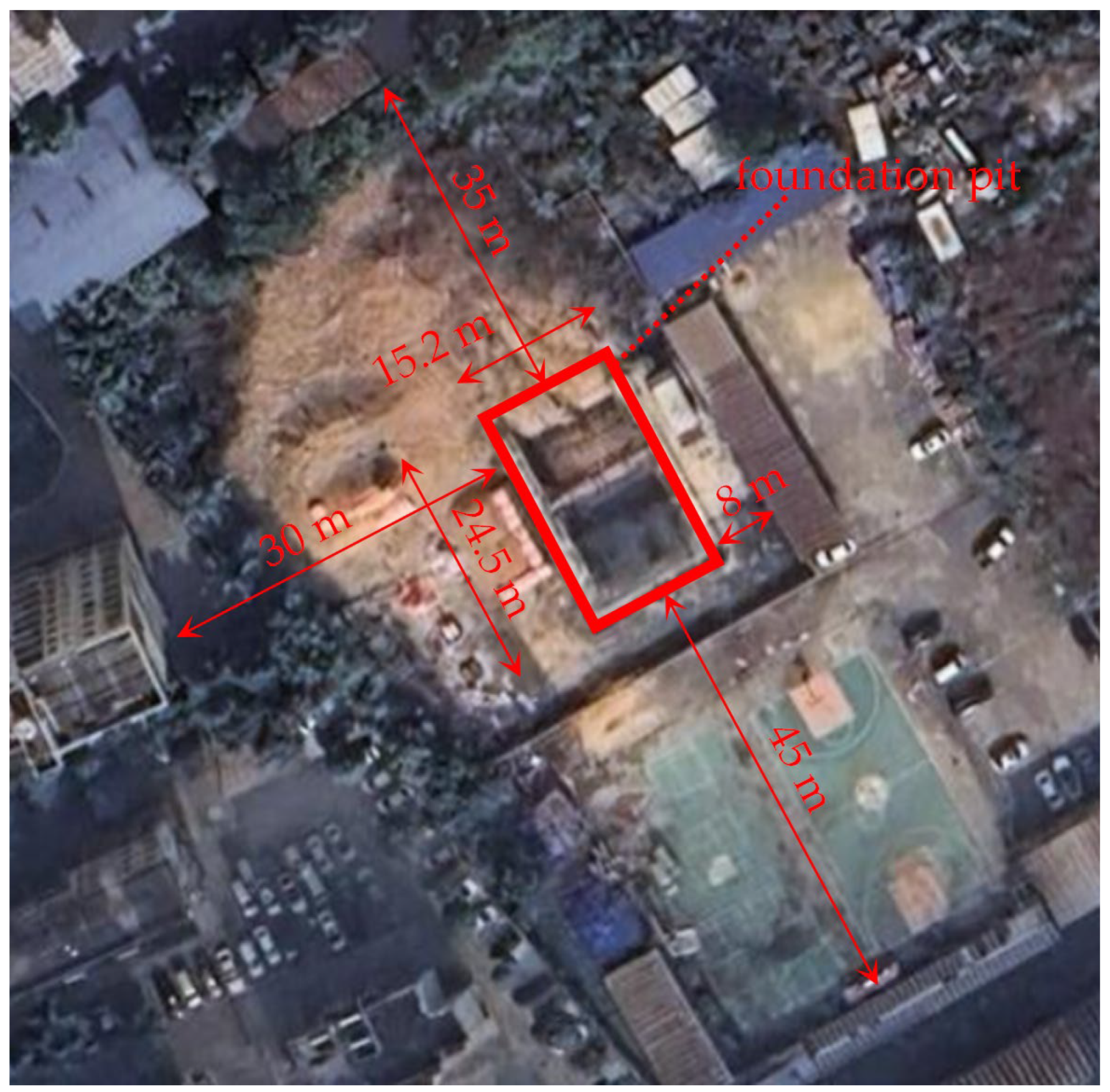
Figure 1. Field experiment site.
Buildings 15 02887 g001
Figure 2. Foundation pit supporting plane diagram.
Buildings 15 02887 g002
Figure 3. Foundation pit supporting elevation diagram.
Buildings 15 02887 g003
Figure 4. Completion of the support installation in the foundation pit.
Buildings 15 02887 g004
Figure 5. Floor plan of pile and crown beam monitoring points.
Buildings 15 02887 g005
Figure 6. Horizontal prestress application procedure: (a) install jack; (b) stopper limit.
Buildings 15 02887 g006
Figure 7. Vertical prestress application procedure: (a) install jack; (b) stopper limit.
Buildings 15 02887 g007
Figure 8. Schematic diagram of the calculation of the stiffness of the non-vertical diagonal brace.
Buildings 15 02887 g008
Figure 9. Support stiffness calculation diagram with vertical diagonal brace.
Buildings 15 02887 g009
Figure 10. Axial force cloud image.
Buildings 15 02887 g010
Figure 11. Axial force cloud image under the installation condition of an inclined support.
Buildings 15 02887 g011
Figure 12. Horizontal displacement: (a) plie 4; (b) plie 5.
Buildings 15 02887 g012
Figure 13. Horizontal displacement of six monitoring piles.
Buildings 15 02887 g013
Figure 14. Pile 6 square torque steel deflection.
Buildings 15 02887 g014
Figure 15. The bending moment: (a) pile 4; (b) pile 5.
Buildings 15 02887 g015
Figure 16. Bending moment distribution curves of the six monitoring piles.
Buildings 15 02887 g016
Figure 17. Change curve of supporting axial force under different working conditions.
Buildings 15 02887 g017
Figure 18. Bending moment curve of the crown beam under different working conditions.
Buildings 15 02887 g018
Figure 19. Model: (a) overall model diagram of the foundation pit; (b) supporting structure model diagram.
Buildings 15 02887 g019
Figure 20. Comparison of horizontal displacement of pile 5.
Buildings 15 02887 g020
Figure 21. Comparative analysis of the horizontal displacement of the supporting pile under vertical prestressed condition: (a) piles 1–3; (b) piles 4–6.
Buildings 15 02887 g021
Figure 22. Comparison of bending moments in pile 5.
Buildings 15 02887 g022
Figure 23. Comparison diagram of the bending moment of the supporting pile under the vertical prestressed condition: (a) piles 1–3; (b) piles 4–6.
Buildings 15 02887 g023
Figure 24. Comparison of supporting axial force.
Buildings 15 02887 g024
Figure 25. The change curve of support displacement under different vertical prestress.
Buildings 15 02887 g025
Figure 26. Foundation axial force change curve under different vertical prestress.
Buildings 15 02887 g026
Figure 27. Characteristic variation curves of pile 3: (a) horizontal displacement; (b) bending moment.
Buildings 15 02887 g027
Table 1. Comparative analysis of theoretical (T) and finite (F) element-derived support stiffness.
With or Without Vertical Diagonal BraceBracing ComponentCalculation MethodSupport Stiffness (MN/m)Error
WithoutUpper chordT81.585.98%
F76.98
Lower chordT81.586.33%
F76.72
WithUpper chordT81.585.71%
F77.17
Lower chordT104.622.90%
F101.67
vertical diagonal braceT25.664.22%
F26.79
Table 2. Support structure material parameter.
ComponentBracing ComponentPoisson RatioElastic Modulus (GPa)
Tangent pilePlate unit0.231.5
Sprayed concretePlate unit0.231.5
Crown beamBeam unit0.231.5
Waist beamBeam unit0.274210
Steel pipe supportBeam unit0.274210
Steel tie rodTension-only truss unit0.274210
Table 3. Geotechnical material parameter.
SoliThickness (m)Gravity (kN/m3)Poisson RatioForce of Cohesion (kPa)Friction Angle (°)Secant Modulus (MPa)Tangent Modulus (MPa)Unloading Modulus (MPa)
Miscellaneous fill118.50.4010.05.03.53.514
Clay319.30.3144.215.211.011.030
Silty clay 1319.80.3240.214.610.710.729
Silty clay 2219.70.3320.010.19.09.028
Rounded gravelNot debunked22.50.3035.030.030.0120
Table 4. Comparative analysis of maximum displacement results of pile 5 under various working conditions.
Construction ConditionMaximum Horizontal Displacement (mm)
Simulated ValuesMeasured ValuesDifferentials
Excavation to −4 m3.7124.0850.373
Apply the first prestress3.1802.8340.346
Excavation to −6 m4.7256.0141.290
Excavation to −7 m6.6036.6180.015
Apply vertical prestress6.5336.5180.015
Table 5. Comparison between the proposed and conventional internal support systems.
Performance MetricConventional SystemProposed SystemImprovement (%)
Max horizontal displacement (mm)15.56.61857%
Equivalent lateral stiffness (MN/m)8010125%
Reusability of bracing componentscustom-welded componentsstandardized modularSignificantly improved
Estimated unit cost (CNY/m)50,00030,00040%
Disclaimer/Publisher’s Note: The statements, opinions and data contained in all publications are solely those of the individual author(s) and contributor(s) and not of MDPI and/or the editor(s). MDPI and/or the editor(s) disclaim responsibility for any injury to people or property resulting from any ideas, methods, instructions or products referred to in the content.