Article

Seismic Performance of Steel Structures with Base-Hinged Columns Under Rigidly and Flexibly Braced Systems

1
Shock and Vibration of Engineering Materials and Structures Key Laboratory of Sichuan Province, Mianyang 621010, China
2
School of Civil Engineering and Architecture, Southwest University of Science and Technology, Mianyang 621010, China
3
Department of Mechanical Engineering, University of Houston, Houston, TX 77204, USA
*
Author to whom correspondence should be addressed.
Buildings 2025, 15(16), 2881; https://doi.org/10.3390/buildings15162881
Submission received: 30 July 2025 / Revised: 10 August 2025 / Accepted: 11 August 2025 / Published: 14 August 2025

Abstract

Steel structures with base-hinged columns are one of the typical forms adopted for rural housing in villages and towns due to their superior seismic resistance, energy efficiency, and environmental benefits. The lateral bracing system plays a crucial role in the ability of steel frames with base-hinged columns to resist horizontal forces. This study investigates the impact of rigid and flexible bracing on the seismic performance of such structures, emphasizing that enhanced ductility—particularly in flexibly braced frames—is essential for seismic resilience in earthquake-prone areas. Two full-scale steel frame models, one with rigid bracing and the other with flexible bracing, were fabricated based on typical rural housing designs and subjected to low-cycle reversed loading tests. The results indicate that the rigidly braced frame undergoes brittle failure, characterized by fractures and buckling at bracing intersections. In contrast, the flexibly braced frame exhibits ductile failure, identified by the bending deformation of tension rods. Despite the flexibly braced frame reaching a peak-load bearing capacity that is only 69.1% (positive direction) and 76.0% (negative direction) of the rigidly braced frame, it achieves ultimate displacements 2.7 times (positive direction) and 2.5 times (negative direction) greater. Additionally, the flexibly braced frame exhibits a stable energy dissipation capacity, with cumulative energy dissipation 1.49 times that of the rigidly braced frame. Numerical simulations were conducted to develop finite element models for both rigidly and flexibly braced frames. The resulting failure characteristics and bearing capacities of the frames were obtained, providing further validation of the experimental results. These findings provide data-supported evidence for promoting steel structures with base-hinged columns in rural housing applications.

1. Introduction

In the western regions of Sichuan Province, China, many traditional residential buildings urgently require reinforcement, repair, or reconstruction. These buildings are predominantly constructed using brick–wood, stone–wood, or earth–wood hybrid structures [1]. The extensive use of these materials often contributes to severe environmental issues, including dust pollution, desertification, and soil erosion, rendering them unsuitable for meeting modern standards of environmental protection and energy efficiency [2,3]. In contrast, steel structures, composed of elements such as steel beams and columns connected by welds, bolts, or rivets, offer advantages including lightweight, strength, high quality, and excellent seismic performance. Additionally, steel structures are well suited for industrialized, standardized, and large-scale production [4,5]. Compared to traditional construction methods, steel structures reduce energy consumption during construction by 65% while providing superior thermal insulation and heat preservation, making them particularly suitable for residential applications in the western regions of Sichuan Province [6,7]. Consequently, replacing traditional structures with steel alternatives in this region holds significant potential for enhancing structural safety and promoting sustainable environmental development.
To facilitate the application of steel structures in this region, a steel structure with base-hinged columns has been introduced [8]. Inspired by the layout of traditional regional structures, this design features reduced cross-sectional dimensions for beam and column components and adopts a modular configuration. The modular design enables rapid on-site assembly without the need for large construction machinery, significantly improving construction efficiency and precision [9]. In this structural system, column bases are hinged, allowing the columns to bear only vertical loads. Under horizontal seismic forces, lateral bracing fully resists the load, efficiently transferring forces primarily through axial loads. Consequently, lateral bracing plays a crucial role in maintaining the stability of this structure under seismic actions [10]. Although the original version of the study employed the term “base-hinged columns” to describe the vertical load-bearing members, it should be noted that the structural behavior does not involve uplift or self-centering mechanisms. The columns are configured with pinned bases that permit rotational movement while preventing moment transmission, which represents a conventional boundary condition commonly adopted in steel frame systems. Horizontal seismic forces are entirely resisted through lateral bracing elements, either rigid or flexible, thereby classifying the investigated structure as a typical steel frame incorporating variable bracing configurations. Notably, reinforcement corrosion and fatigue damage are the main factors affecting the durability of reinforced concrete structures. Appropriately increasing the chromium content in stainless steel reinforcement has a positive effect on improving its corrosion resistance and fatigue resistance [11].
The role of lateral bracing in enhancing the seismic performance of steel structures has garnered significant attention [12,13,14]. Zhang et al. [15,16] developed two types of frame structures: one utilizing self-compacting concrete-filled steel tube columns connected to H-shaped steel beams, and the other adopting ordinary C35 concrete filling. The seismic performance of the structures was evaluated through quasi-static tests. Various wall types, including clay hollow-brick infill walls [17], lightweight external wall panels [18], composite steel shear walls [19], and cold-formed thin-walled steel shear walls [20], have been extensively studied for their influence on the mechanical performance of steel frames. To further enhance the seismic performance of walls, Liu et al. [21] proposed a fully prefabricated structure comprising H-shaped steel beams and self-compacting concrete-filled steel tubular walls. Research consistently indicates that walls can enhance the lateral resistance of steel frames, but a reliable connection between the steel frame and the wall is essential. Since steel bracing and steel frames are composed of the same material, their connection is inherently more dependable. Consequently, steel-braced frames have been widely adopted to resist horizontal forces in structures [22,23,24]. Jay et al. [25] analyzed the mechanisms and seismic load patterns of cross-braced beams in two-story frames, focusing on the effects of yielding beams on critical components such as bracing and connections. Similarly, Yoo et al. [26] examined the nonlinear cyclic performance of multi-story X-braced frames and their gusset plate connections, proposing an inelastic analysis model to predict yielding mechanisms, failure modes, deformation capacity, and the initiation of cracking and fracture in key elements. Yu et al. [27] conducted low-cycle cyclic loading tests on K-shaped and Y-shaped eccentrically braced steel frames. The results demonstrated that both frame types exhibited excellent ductility and energy dissipation capacity. The K-shaped frames showed greater vertical deformation than the Y-shaped frames. While the Y-shaped frames had lower lateral stiffness compared to the K-shaped frames, they exhibited relatively high initial stiffness and commendable seismic performance. Despite these advancements, the seismic performance of lateral bracing in steel frames with base-hinged columns remains a relatively underexplored area. Different bracing systems offer practical guidance for structural design and are essential for improving the design of more efficient and resilient seismic structures, particularly in base-hinged column steel frames that require both flexibility and rigidity.
To comprehensively and systematically evaluate the seismic performance of structures, E. Aydin et al. [28,29] (Rehabilitation of Planar Building Structures using Steel Diagonal Braces and Dampers) investigated the mechanical behavior of adjacent planar steel frames interconnected by rigid rods under seismic excitation. They also explored the strengthening effect of steel diagonal braces on planar building structures featuring weak stories. Leveraging the SAP 2000 structural analysis software (https://www.csiamerica.com/products/sap2000, accessed on 30 July 2025), they developed structural models and conducted in-depth structural analyses. Employing the time history analysis method, the researchers analyzed the structural responses using the El Centro NS-direction seismic acceleration records. Inter-story displacement, inter-story drift angle, and floor acceleration were selected as key indicators to characterize the structural responses. Furthermore, machine learning technology has promising prospects in the engineering field. Md. Hasan Imam et al. [30] studied the method of using machine learning technology for advanced seismic performance prediction in structural engineering. The study utilized ETABS software (https://www.csiamerica.com/products/etabs, accessed on 30 July 2025) to conduct nonlinear dynamic analysis (NDA) on steel moment-resisting frames (SMRFs) with different configurations located in seismic zone II and on site class D soil. A large dataset containing 292 models and 29,200 data points was generated to train the machine learning model, aiming to predict the maximum inter-story drift ratio (M-IDR). Petros C. Lazaridis et al. [31] investigated the capability of ten machine learning algorithms in predicting structural damage to an eight-story reinforced concrete frame building under single and consecutive earthquake actions. Based on this, the study used the initial damage state of the structural system and 16 well-known ground motion intensity measures as the characteristic parameters of the machine learning algorithms, aiming to predict the structural damage after each earthquake event.
This study examines the seismic performance of steel frame structures with base-hinged columns under two types of bracing systems: rigid and flexible. Quasi-static tests were conducted to evaluate the stiffness, strength, ductility, and hysteretic energy dissipation capacity of the structures. A comparative analysis assessed the impact of the two lateral bracing systems on the seismic performance of steel frames. The findings offer data-supported evidence for implementing this structural system in rural housing within villages and towns.

2. Materials and Methods

2.1. Steel Structures with Base-Hinged Columns

Figure 1 illustrates the structural system and force distribution of the steel frame with base-hinged columns. This structural system is specifically developed for rural residential buildings, particularly low-rise standalone houses with up to three stories. Considering the construction scale and functional requirements of rural housing, the column unit length is set at approximately 3 m, while the beam unit length is kept within 5 m. Based on the span and depth calculations for traditional residential buildings, the beam cross-section is specified as 250 mm × 125 mm × 6 mm × 9 mm, and two types of square steel tube column cross-sections, 100 mm × 100 mm × 6 mm and 100 mm × 100 mm × 4.5 mm, are adopted to meet the structural layout requirements of most rural housing designs, as shown in Figure 1a. Compared to traditional structures, this system reduces the cross-sectional dimensions of beams and columns, limiting the weight of individual components to less than 50 kg, calculated as the product of the component volume and the steel density. This lightweight design facilitates assembly without the need for construction machinery, making it particularly suitable for building houses in remote mountainous regions.
According to the performance-based seismic design (PBSD) method for steel structures, seismic design strategies typically involve a balance between high bearing capacity with limited ductility and lower bearing capacity with enhanced ductility, depending on the performance objectives and anticipated seismic demands. Due to the lightweight nature of the ground-floor residential structure and its axial force-dominated load characteristics, the design prioritizes high ductility over high bearing capacity. This approach ensures adequate deformation capacity and energy dissipation, which are essential for maintaining structural safety and performance under seismic loading. For the design, an elastic design based on a moderate seismic hazard, or design earthquake, is adopted. This approach allows the use of S5-grade beam cross-sections, maximizing the lightweight and high-strength properties of the steel structure. The design ensures good seismic performance while minimizing steel usage. The column base of the steel frame with base-hinged columns is connected to the foundation using anchor bolts. Under horizontal seismic forces, the column only transmits vertical loads. The lateral force is primarily resisted by the diagonal braces, as shown in Figure 1b. Therefore, selecting appropriate diagonal braces is essential for ensuring the overall stability of the structure and achieving an efficient axial-force-dominated load transfer system.

2.2. Specimen Design

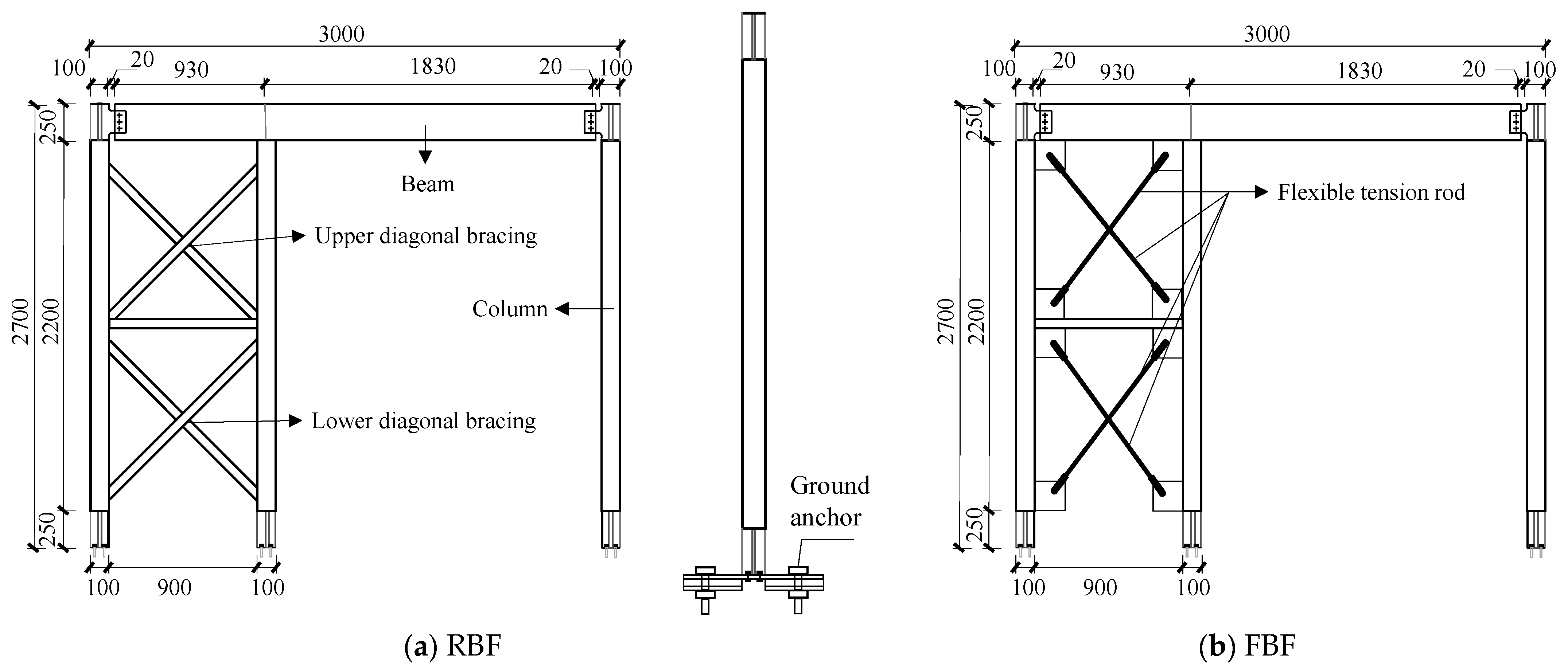
Before conducting the experiment, the test specimens must be precisely designed based on the actual functional requirements of the structure [32]. Based on the structural system of the base-hinged column steel frame (Figure 1a), a single frame was designed as the test specimen at a 1:1 scale. The detailed dimensions and construction of the frames are shown in Figure 2. Two models were developed, including a rigidly braced frame (RBF) and a flexibly braced frame (FBF). Both frames shared identical overall dimensions of 2700 mm × 3000 mm, with a height-to-width ratio of 0.9. The square steel tube columns measured 100 mm × 100 mm × 6 mm in cross-section and had a height of 2700 mm. The I-beams had cross-sectional dimensions of HN250 mm × 125 mm × 6 mm × 9 mm and a length of 2760 mm. To ensure comparability, both specimens were designed with the same geometric dimensions, material properties, and boundary conditions. The only difference between the two specimens was their lateral bracing systems, where the RBF utilized rectangular steel tubes for bracing and the FBF employed flexible tension rods.
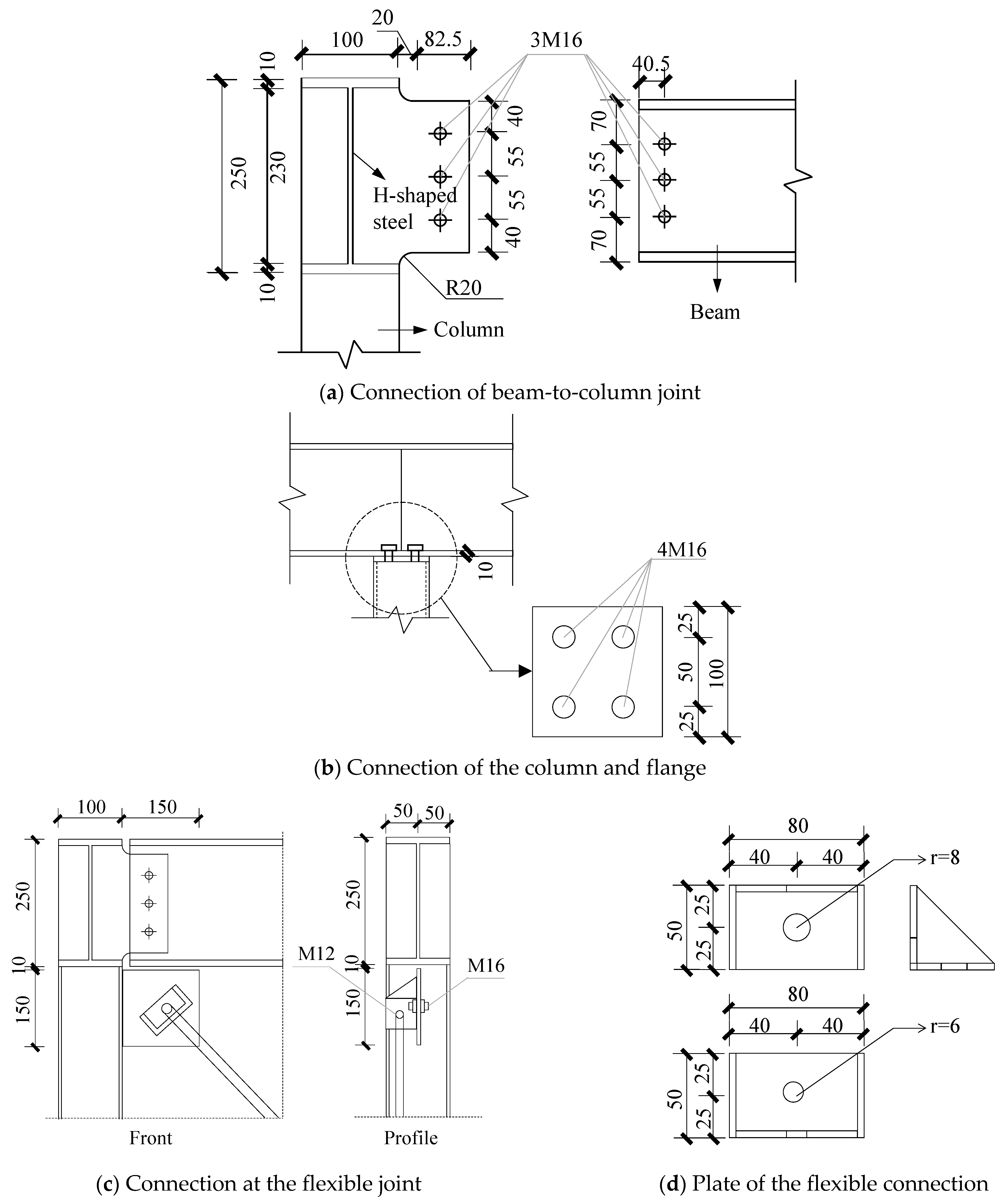
The connections were designed to ensure reliability and stability under seismic loading. For the base-hinged columns, the base connections were configured to allow rotational freedom, enabling the columns to shake under lateral loads without transferring excessive moments to the foundation. This was achieved by using ground anchors to secure the column base to the foundation. Figure 3 illustrates the connection details of the two frames. An H-shaped steel with dimensions of 250 mm × 100 mm × 10 mm × 10 mm was welded to the top of the columns. A steel plate is welded to the right side of the H-shaped steel to connect with the beam flange. The beam and column were joined using three standard M16 bolts (grade 4.8), forming the beam–column joint, as shown in Figure 3a. The middle column was connected to the lower flange of the H-beam with four embedded M16 bolts (grade 4.8), as depicted in Figure 3b. To maintain experimental consistency, all bolts were tightened to 60 kN·m using a torque wrench.
For the lateral bracing systems, the connections between the braces and the frames were designed to ensure effective load transfer while maintaining the intended flexibility or rigidity of the system. In the RBF, the diagonal bracing consists of square steel tubes measuring 50 mm × 50 mm × 2 mm, which are directly welded to the square steel tube columns. In the FBF, the rigid diagonal bracing is replaced by Q235B-grade steel rods with a diameter of 12 mm, connected to the structural columns using connectors, as shown in Figure 3c,d.

2.3. Material Properties

Samples of steel with varying thicknesses, used in the experiment, were subjected to uniaxial tensile tests. In accordance with the standards GB/T 228-2010 and GB/T 2975-2018 [33,34], the mechanical properties of the specimens were tested using a 30 ton electric servo universal material testing machine. The section ratio of the tested specimens was 35.65. Based on the location of the steel, the specimens were divided into six groups, with three specimens per group. All specimens were processed from the same batch of steel and cut into tensile specimens using wire electrical discharge machining. The experiment followed a step-by-step loading procedure until specimen failure. The average material property parameters for each group are presented in Table 1.

2.4. Test Procedures

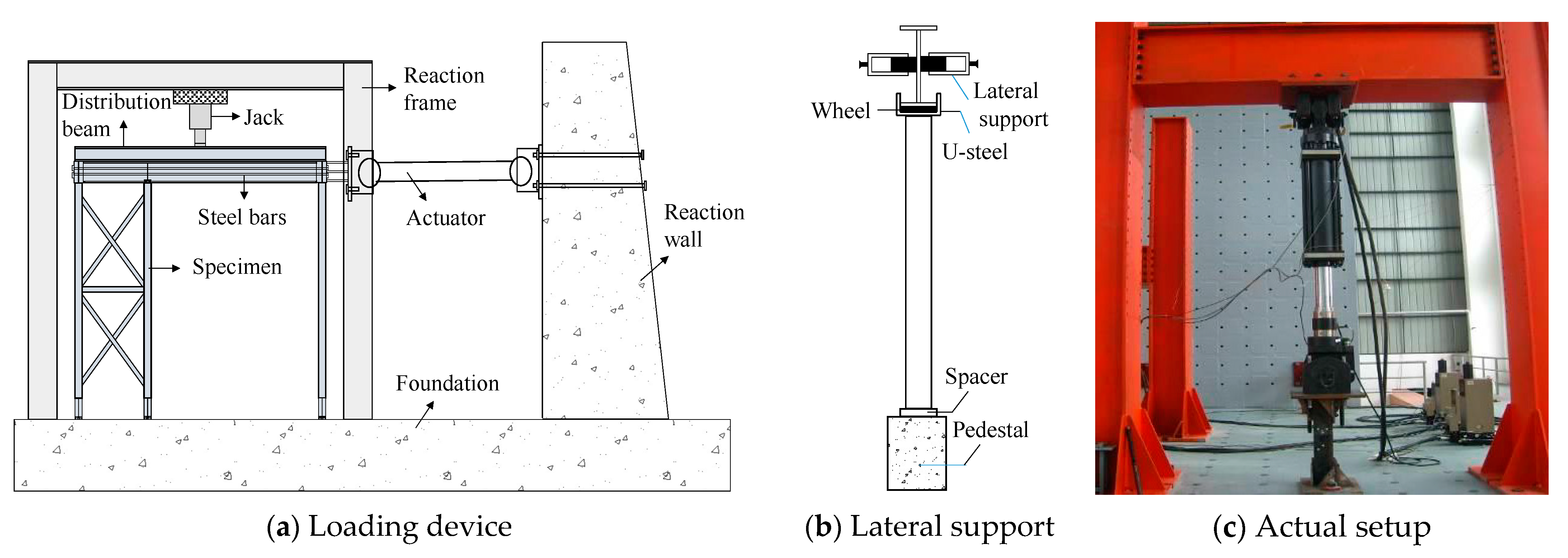
The experiment employed low-cycle reverse loading using an MTS electro-hydraulic servo loading system. This system had a maximum load capacity of ±1000 kN, a displacement range of ±500 mm, and a maximum loading frequency of 5 Hz. The test setup included the MTS electro-hydraulic servo-controlled testing machine, a reaction frame, a reaction wall, a distribution beam, and a foundation beam, as shown in Figure 4a. The MTS system applied horizontal low-cycle reverse loads to the specimens, enabling the observation of failure characteristics and the measurement of data such as hysteresis curves, load bearing capacity, and horizontal displacement. The loading end of the specimen was connected with four 25 mm diameter steel bars to apply the horizontal low-cycle reverse load. The distribution beam, an I-beam, was positioned with its top in contact with the jack and its bottom in contact with the specimen, transferring the load from the jack to the specimen. To reduce friction and ensure uniform distribution of vertical forces, channel steel and rollers were placed between the distribution beam and the specimen. Rolling supports were also applied on both sides of the distribution beam to prevent out-of-plane instability during loading, as shown in Figure 4b.
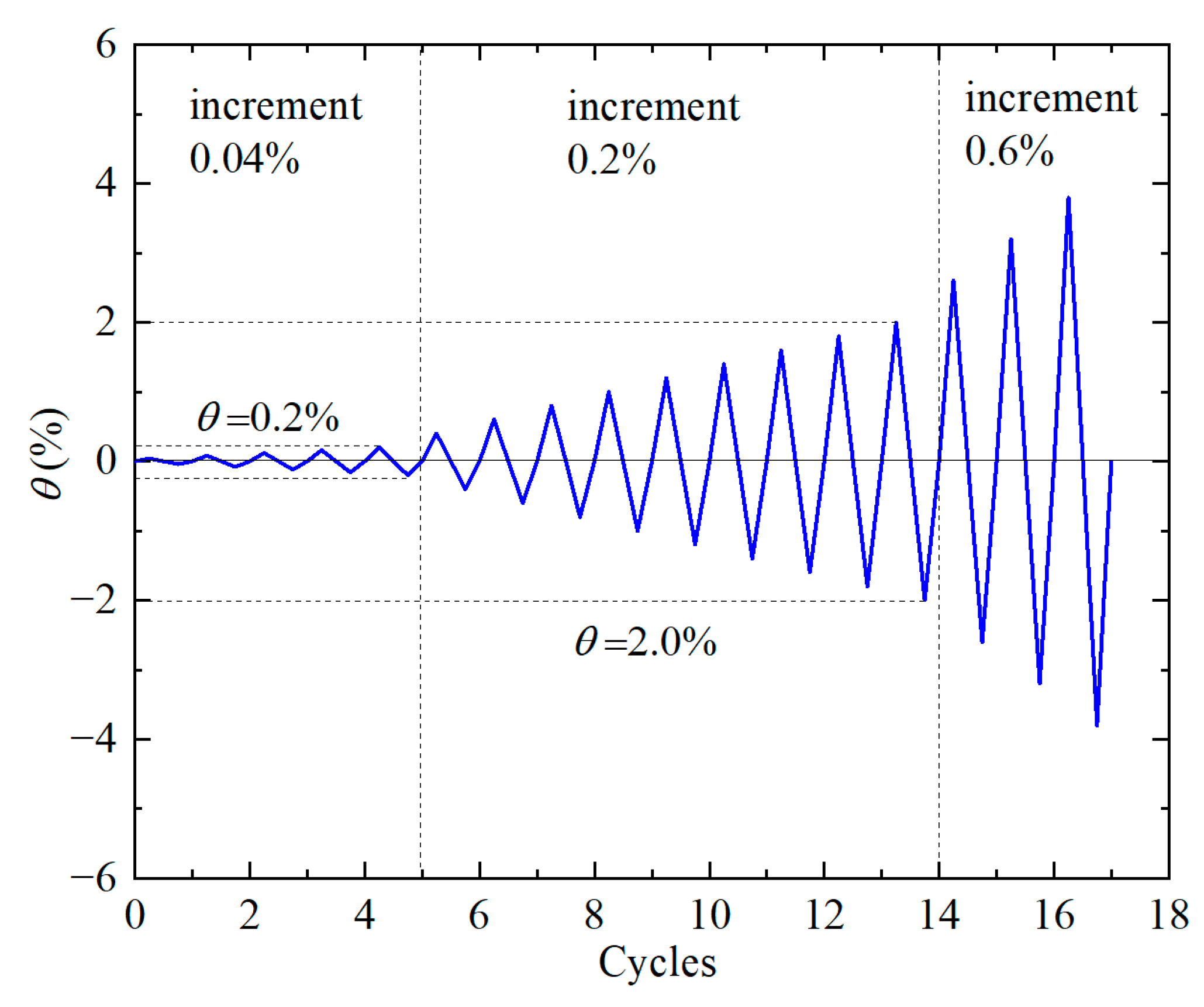
The loading process in the experiment was divided into vertical and horizontal loading phases. During the vertical loading phase, the axial compression ratio of the specimen was controlled. Due to the limitations of experimental conditions and to ensure safety, axial compression was applied at a design value of 0.3 MPa using a manual hydraulic jack, which was maintained constant throughout the test. For horizontal loading, displacement control was applied in accordance with the loading protocols outlined in JGJ/T 101-2015 [35] and ATC-24 (1992) [36], as shown in Figure 5. The horizontal loading process was displacement-controlled and based on inter-story drift ratios, following the protocols outlined in JGJ/T 101-2015 and ATC-24. These protocols simulate lateral deformation demands under seismic loading. Specifically, when the inter-story drift angle was θ ≤ 0.2%, the displacement increment was 0.04%; for 0.2% ≤ θ ≤ 2.0%, the increment was 0.2%; and when θ ≥ 2.0%, the increment was 0.6% until failure occurred. Each displacement level was cycled three times, reflecting low-cycle loading behavior typically used in quasi-static seismic simulation, until it reached 0.2%. For inter-story drift angles between 0.2% and 2.0% (0.2% ≤ θ ≤ 2.0%), the displacement increment was set at 0.2%. When the inter-story drift angle reached θ ≥ 2.0%, the displacement increment was 0.6% until failure occurred. This method provides a reliable approximation of structural deformation behavior under moderate-to-severe seismic excitations, without applying actual dynamic ground motions.

3. Test Results

3.1. Experimental Phenomena

Figure 6 illustrates the experimental phenomenon of the RBF under cyclic loading. A distinct friction sound was heard between the steel components when the inter-story drift angle reached 0.4%. At an inter-story drift angle of 0.8%, a visible indentation was observed at the intersection of the lower diagonal bracing, with a depth of approximately 8 mm (Figure 6a). When the inter-story drift angle increased to 1.0%, a fracture occurred at the lower diagonal bracing (Figure 6b). Continued loading up to an inter-story drift angle of 1.8% revealed buckling at the upper diagonal bracing. At an inter-story drift angle of 2.0%, a noticeable indentation appeared in the diagonal bracing at the upper part (Figure 6c). When the inter-story drift angle reached 2.6%, fractures occurred at the connections of both the upper and lower layers of diagonal bracing. At this moment, the steel bracing had lost its lateral load-carrying capacity, and the loading was stopped.
Figure 7 illustrates the experimental phenomena of the FBF under cyclic loading. As flexible tension rods replaced the rigid bracing, the test phenomena were less pronounced in the early stages, with occasional friction sounds heard between the steel components. When the inter-story drift angle reached 2.0%, buckling was observed at the connection between the leftmost column and the lateral bracing (Figure 7a). At an inter-story drift angle of 2.6%, significant bending occurred at the connection between the flexible tension rod and the end plate in the lower right corner (Figure 7b). When the inter-story drift angle reached 5.0%, the actuator reversed and reached its limit, causing the negative displacement value to remain constant at 5.0%. When the positive loading reached an inter-story drift angle of 5.6%, the load value dropped below 85% of the peak load, and the flexural tension rod underwent significant bending, prompting the test to be stopped (Figure 7c).
Based on the experimental observations of the two specimens, it can be concluded that the failure characteristics of the rigidly braced frame initially manifested at the lower diagonal bracing, eventually leading to a loss of load-carrying capacity due to fractures at both bracings. In contrast, the failure characteristics of the flexibly braced frame primarily occurred at the flexible tension rods. Instead of fracture failure, the frame underwent significant deformations. Therefore, the rigidly braced frame predominantly exhibited brittle failure, while the flexibly braced frame demonstrated greater ductility.

3.2. Hysteresis Curve

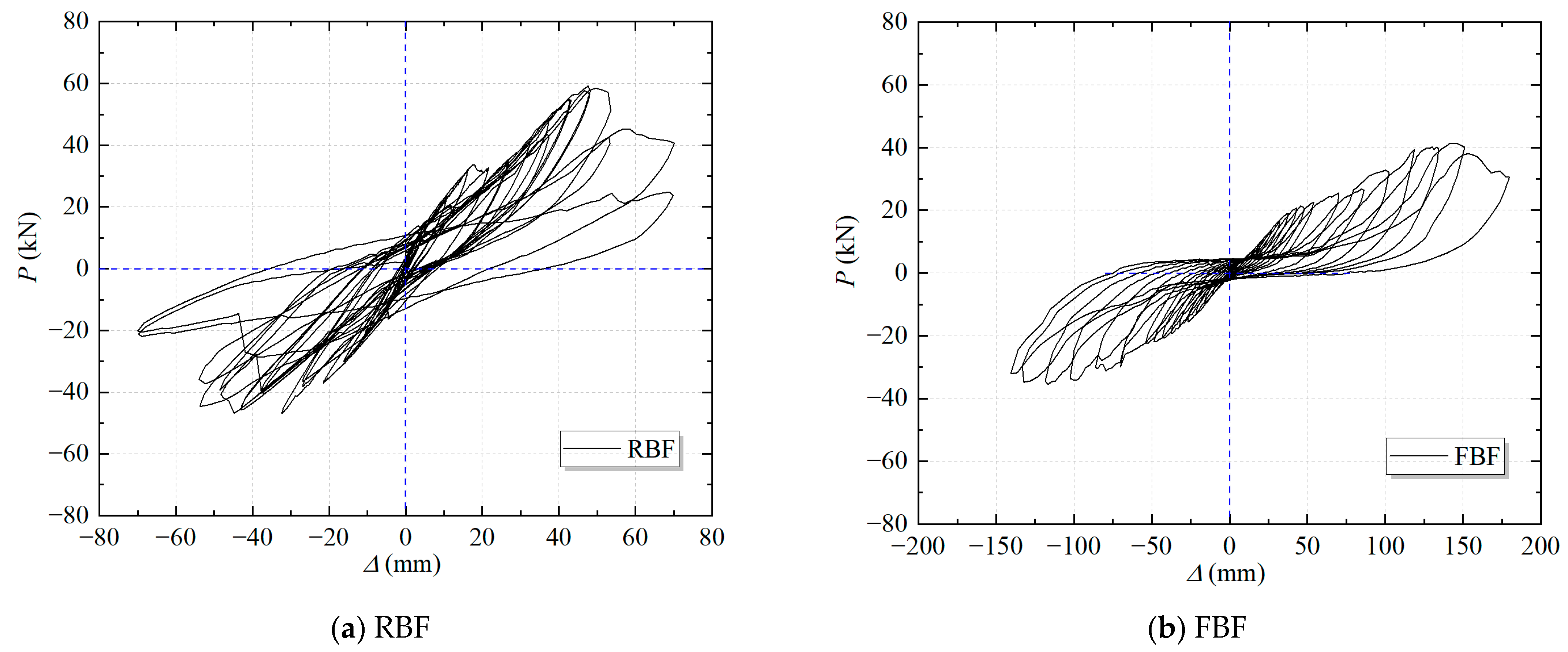
Based on the measurements from the displacement gauges and sensors, the hysteresis curves for both sets of specimens were obtained, as shown in Figure 8. To provide a clearer data presentation, the deformation of the specimens was represented by horizontal displacement, which substitutes for the displacement angle in the loading protocol. During the initial loading phase, the hysteresis curves of both frames are nearly symmetrical, indicating that both frames are in the elastic stage with no residual deformation, and the deformations in both directions are almost identical. As loading increases, significant differences begin to appear in the hysteresis curves of the two specimens. In the RBF, a sudden decrease in stiffness occurs repeatedly at a horizontal displacement of approximately 20 mm, due to the fracture of the lower diagonal bracing. A second drop in stiffness occurs at a horizontal displacement of 50 mm, corresponding to the fracture of the upper diagonal bracing. In contrast, in the FBF, the stiffness begins to decrease gradually at a horizontal displacement of around 40 mm, due to buckling of the lateral steel components. The flexibly braced frame did not exhibit the sudden fracture behavior seen in the rigidly braced frame. Instead, the hysteresis loops are relatively smoother, although the pinching effect of the loops is more pronounced.

3.3. Skeleton Curve

Figure 9 shows the skeleton curves, which were obtained by connecting the peak points of each cycle in the hysteresis curves. Using the energy method, the yield point, peak point, and ultimate point of the skeleton curves were identified, as shown in Table 2. Among them, the ultimate displacement refers to the point at which the bearing capacity reaches 85% of the peak bearing capacity, or the point at which the structure is no longer suitable for further loading due to significant damage. According to the test results, ultimate displacement is defined as the maximum displacement the structure can undergo before its lateral bearing capacity deteriorates, leading to significant damage or a loss of function. From Figure 9, it is evident that the load-carrying capacity of the FBF is consistently lower than that of the RBF, but its displacement is significantly larger. Further analysis of Table 2 reveals that the FBF yields later than the RBF, with a yield load that is only 52.1% (positive direction) and 58.0% (negative direction) than that of the RBF. Similarly, the peak load of the FBF is 69.1% (positive direction) and 76.0% (negative direction) lower than that of the RBF. However, the ultimate displacement of the FBF is 2.7 times (positive direction) and 2.5 times (negative direction) greater than that of the RBF. The ductility factor μ further indicates that the FBF has ductility greater than 3 in both directions, demonstrating its superior ductility and ability to sustain larger deformations under seismic loading. This indicates that flexible bracing enhances the ductility of the frame with base-hinged columns, as inelastic deformation occurs in the bracing elements rather than in the columns. Additionally, the experimental results reveal that when both specimens reached their maximum displacement, no significant damage was observed at the column bases, suggesting that the current ultimate displacement had not yet reached the displacement threshold of the base-hinged column.

3.4. Strength

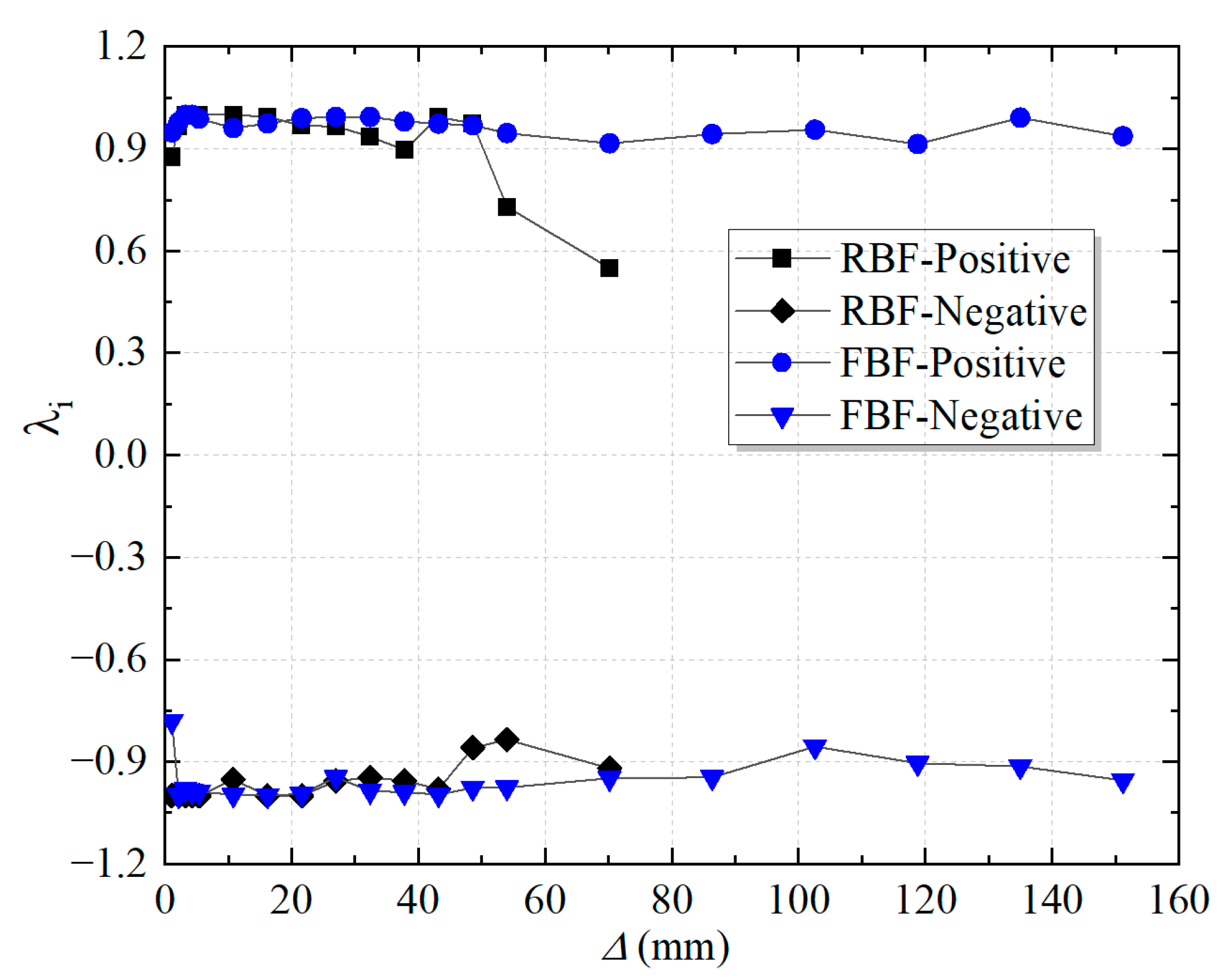
The strength variation within the structure during the loading process can be derived from the hysteresis curves, and it is categorized into local load-strength degradation λi and overall load-strength degradation λj. Specifically, λi is defined as the ratio of the peak load in each cycle to the peak load in the first cycle at the same load level. λj represents the ratio of the maximum load at each level to the overall peak load of the specimen. The corresponding expressions are as follows:
λ i = P j i P j 1
λ j = P j P max
Here, P j 1 denotes the load value at the peak of the first cycle during the j-th load level; P j i denotes the load value at the peak of the i-th cycle during the j-th load level; and P m a x represents the peak load of the specimen.
Based on Equations (1) and (2), λi and λj for both sets of specimens are shown in Figure 10 and Figure 11. The strength degradation curves reveal that, initially, the strength of both frames is nearly identical. However, as displacement increases, the RBF exhibits a significant reduction in strength at displacements of 53.6 mm and 69.9 mm, indicating irreversible damage occurred at these deformations, causing the structure to lose its ability to sustain strength. In contrast, the strength of the FBF maintains stable strength throughout the loading process, even under large deformations. The overall strength degradation curves for both frames exhibit similar trends where λj increases with displacement until the maximum load is reached, and then decreases as displacement continues. Experimental observations indicate that the RBF undergoes yielding of the diagonal braces and fracture of welds at the brace connections, resulting in a rapid reduction in strength. In contrast, the FBF exhibits only a gradual decrease in strength during the later stages of loading, indicating its ability to maintain strength even under large deformations.

3.5. Stiffness

Stiffness represents the capacity of the specimen to resist deformation, which is defined as:
K j = j = 1 n P j i i = 1 n u j i
Here, u j i represents the deformation corresponding to the maximum load of the i-th cycle at the j-th load level.
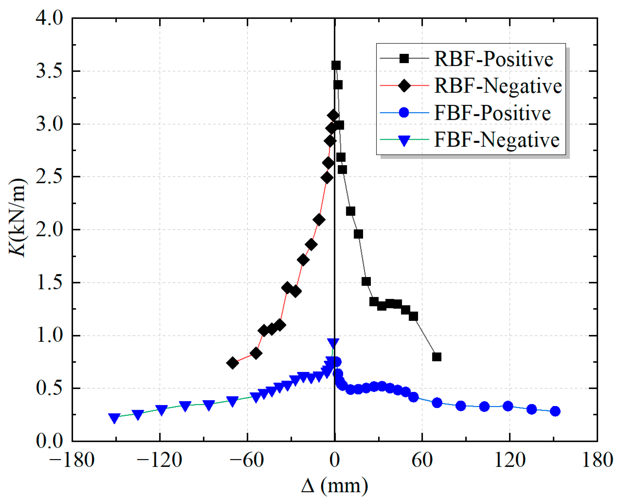
Figure 12 indicates the stiffness degradation of both specimens. The initial stiffness of the RBF is 3.56 kN/mm (positive direction) and 3.08 kN/mm (negative direction), while the stiffness of the FBF is significantly lower, at 0.75 kN/mm (positive direction) and 0.937 kN/mm (negative direction). As loading progresses, compared to the empirical stiffness degradation relationships proposed by Xiangyong Ni and Shuangyin Cao [37], the RBF exhibits a degradation trend consistent with brittle lateral-force-resisting systems, while the FBF shows a more gradual degradation similar to ductile systems. Additionally, FEMA 356 suggests that structures exhibiting a stiffness reduction below 30% of their initial stiffness may be considered severely damaged. The RBF falls below this threshold, while the FBF remains above it, indicating better post-yield stiffness retention with its final stiffness at 37.3% of its initial value. These findings suggest that the RBF is suitable for structures subjected to small deformations, where high stiffness can be maintained. In contrast, the FBF is more suitable for structures subjected to large deformations, as it can maintain stability even under significant deformation.

3.6. Energy Dissipation

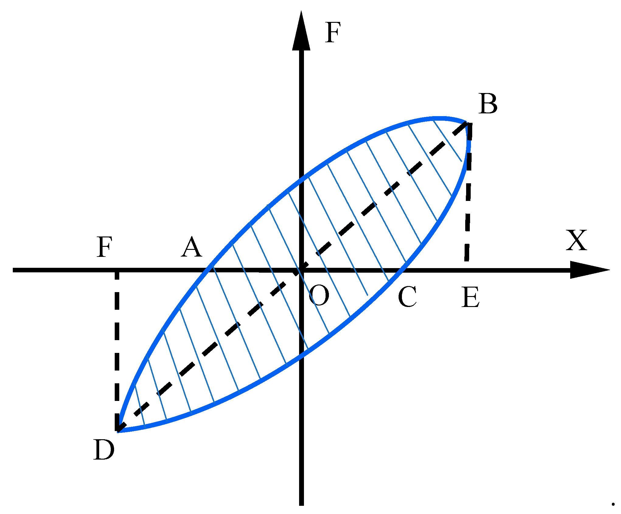
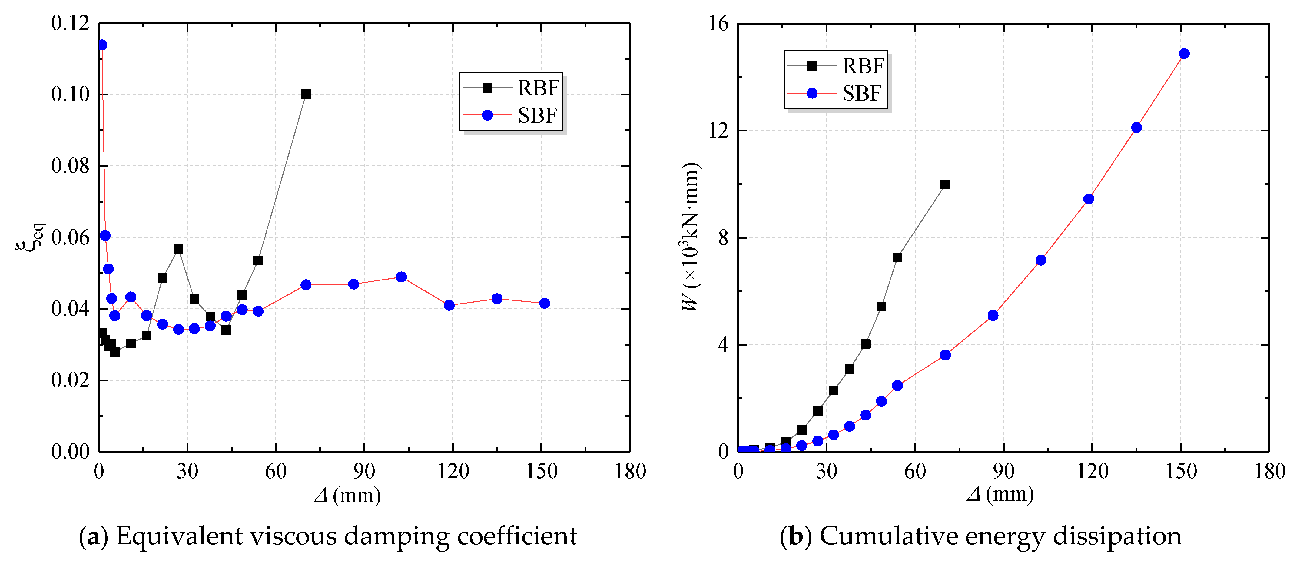
The energy dissipation capacity of a structure is determined by the area S enclosed by each hysteresis loop, as illustrated in Figure 13. In accordance with the guidelines provided in JGJ/T 101-2015 [35], the seismic performance of the structure is evaluated using the equivalent viscous damping coefficient, ζeq, which can be expressed as:
ζ e q = 1 2 π S A B C + C D A S O B E + O D F .
Figure 14 compares the energy dissipation capacities of the two specimens. The equivalent viscous damping coefficient, ζeq, indicates that the energy dissipation capacity at each loading displacement is similar for both structures, generally around 0.04. The RBF exhibits two significant increases in ζeq, corresponding to the fractures and buckling within the frame. However, the improvement in energy dissipation due to these failures is limited and does not significantly enhance the overall seismic performance of the structure. In contrast, the flexible support frame maintains a stable ζeq throughout the entire loading process, without a significant decrease as the displacement increases. This is because the FBF experienced no significant damage under horizontal loading. Further analysis of cumulative energy dissipation reveals that although the RBF dissipates more energy during the initial loading phase, its total energy dissipation is 9.98 × 10³ kN·mm due to structural failure. On the other hand, the total energy dissipation of the FBF reaches 14.88 × 10³ kN·mm, which is 1.49 times that of the RBF. This indicates that the seismic performance of the FBF is superior to that of the RBF.

4. Finite Element Simulation

To further investigate the mechanical performance and failure characteristics of steel structures with base-hinged columns under horizontal action, a steel frame model was developed using the ABAQUS finite element software. The analysis considered both geometric and material nonlinearity to study the structural mechanical behavior and failure modes.

4.1. Modeling Details

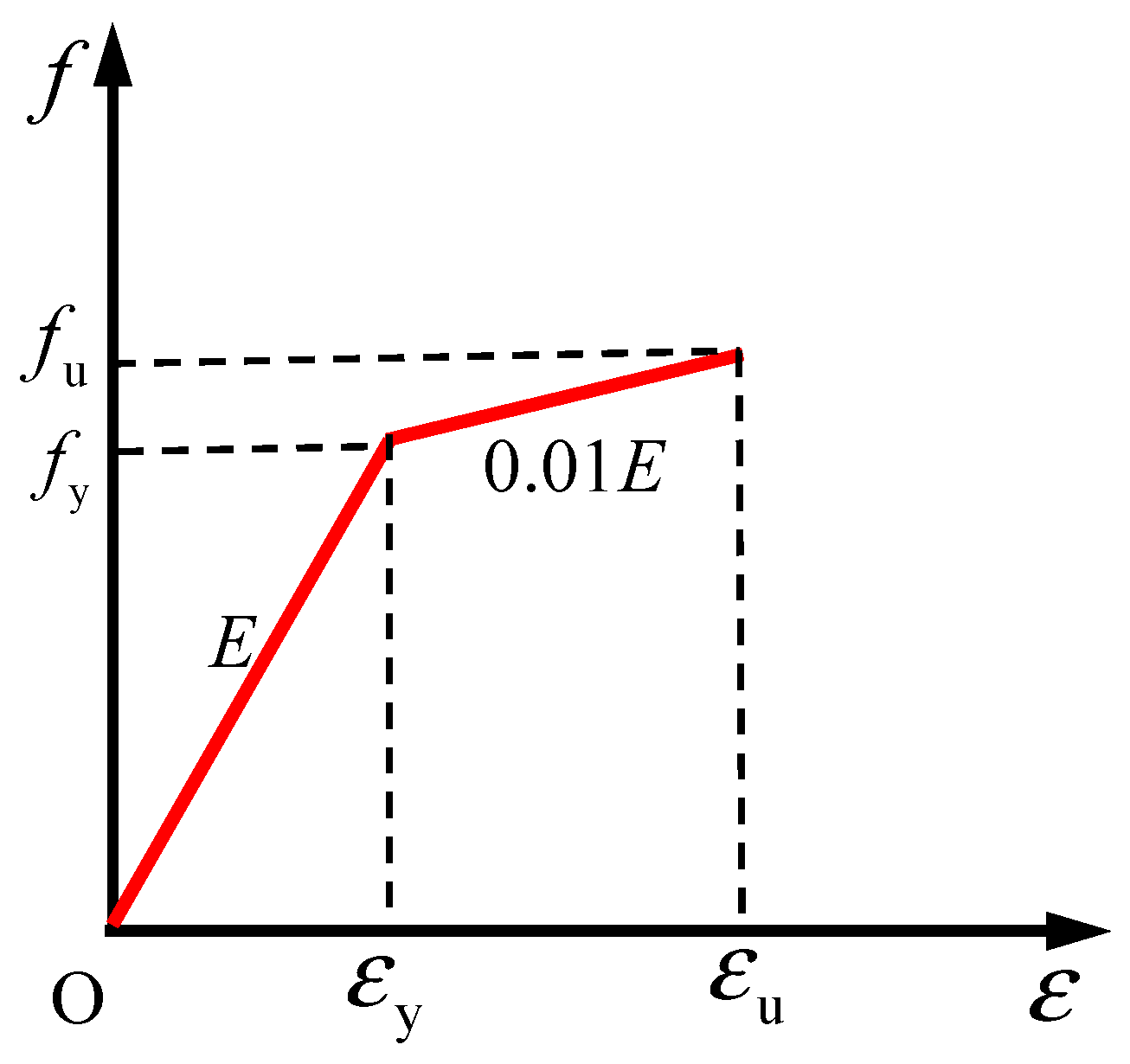
In this finite element model (FEM), developed using Abaqus 2022 [38], the tensile strength of the material was determined using the experimental data provided in Table 1, and the von Mises yield criterion was adopted. The stress–strain relationship was determined using a three-line descending segment constitutive model, as expressed in Figure 15.
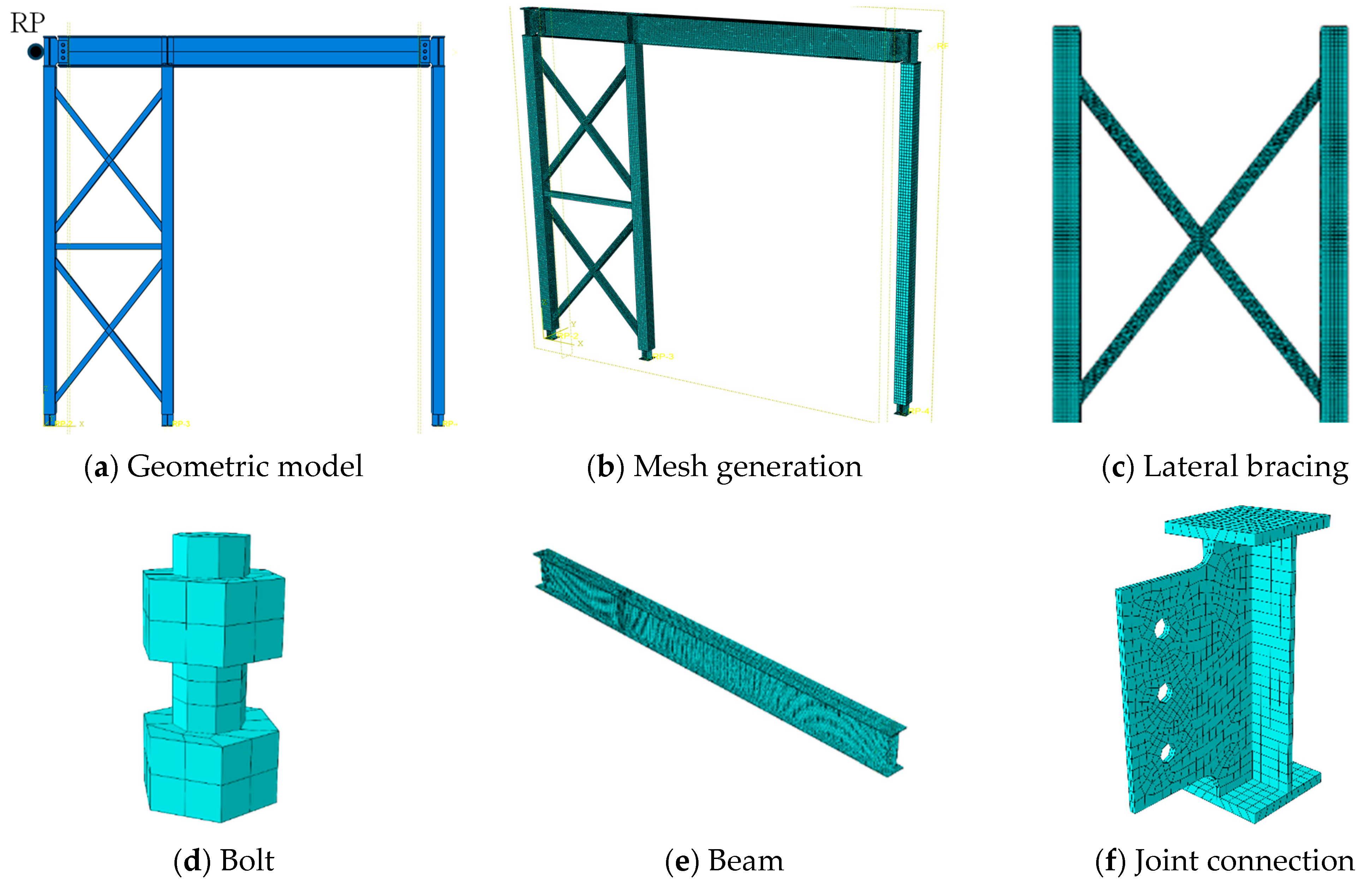
In the FEM, tie constraints were utilized to connect the cross joints with the upper and lower end plates. To facilitate the output of load and displacement values at the loading end, a reference point (RP) was established at the loading end (Figure 16a). Kinematic coupling constraints were applied to the contact surface between the reference point and the frame column to enable horizontal low-cycle repeated loading. The contact interactions between bolts, connection plates, and steel beams were considered, with normal contact defined as hard contact and tangential contact modeled using the Coulomb friction model with a penalty coefficient of 0.3. Similarly, the contact between the connection plates and I-beams was modeled with normal contact set as hard contact and tangential contact using the Coulomb friction model with a friction coefficient of 0.3.
The finite element analysis consisted of three steps: (1) applying a preload of 170 kN to the bolts, (2) fixing the bolt length to maintain the preload, and (3) applying displacement-controlled cyclic loading to the structure. In the model, I-beams, joints, and bolts were represented using C3D8R solid elements, while steel tube columns were modeled with S4R shell elements. The model was meshed, and the final finite element analysis configuration is illustrated in Figure 16.

4.2. Comparison of Failure Modes

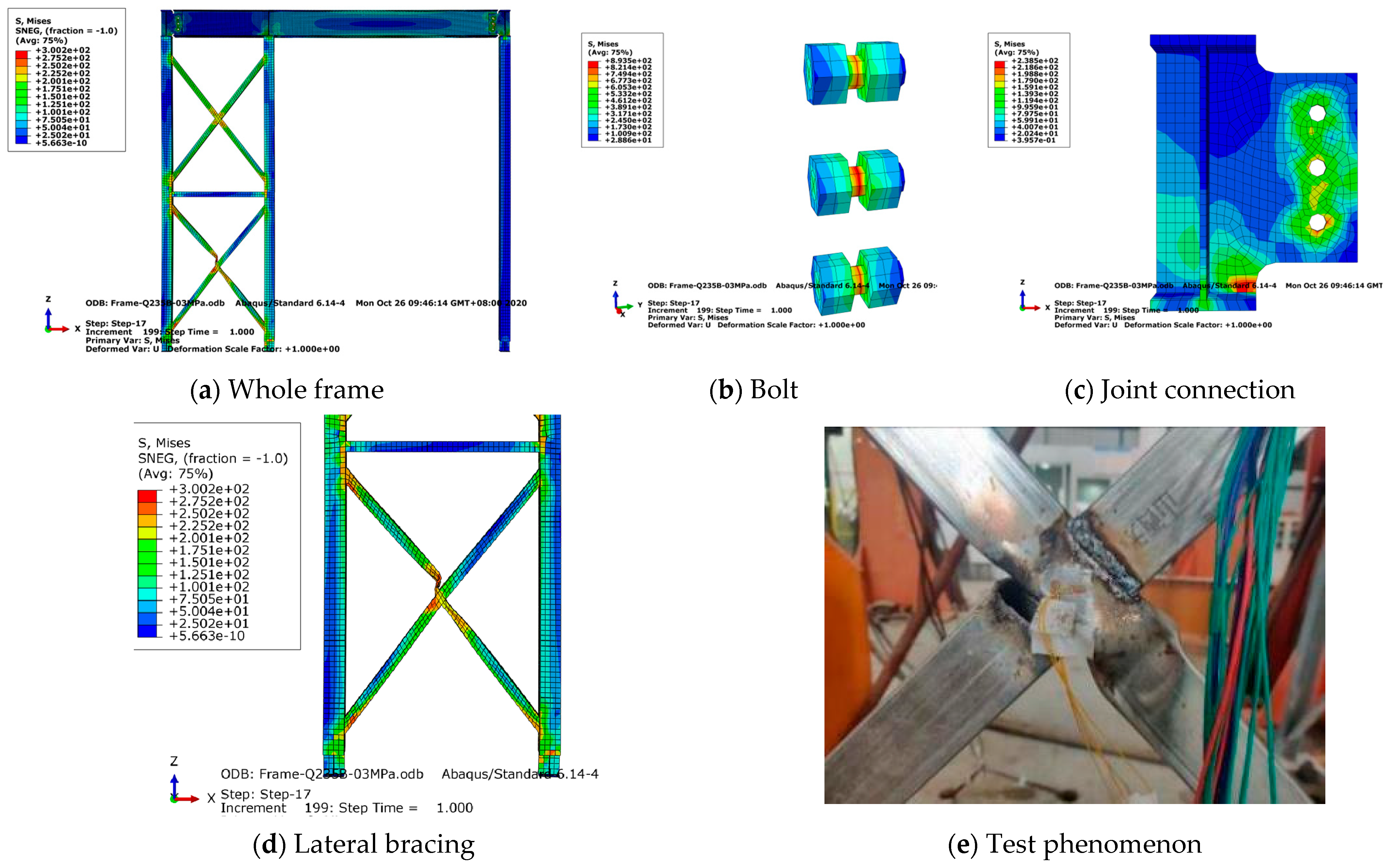
To validate the accuracy of the FEM, the stress distribution characteristics of the model under horizontal loading were analyzed and compared with experimental results, as shown in Figure 17. The stress–strain cloud diagrams for various positions on the specimen reveal that stress is primarily concentrated at the cross-connection locations of the upper and lower diagonal braces, with the stress on the lower brace being greater than that on the upper brace (Figure 17a). This phenomenon was consistent with the test phenomenon, which also indicated that lower brace deformation occurred first. At the bolt locations, stress is mainly concentrated at the center of the rod (Figure 17b). At the beam–column joints, stress is concentrated around the bolt holes (Figure 17c).
The finite element analysis indicates that the bolts, connection joints, and I-beams did not reach their failure strength, consistent with experimental observations where these components neither yielded nor failed. Moreover, the simulation clearly captures significant buckling at the cross-connection of the diagonal braces (Figure 17d), which closely corresponds to the failure mode observed in the RBF specimen experiment. In the experiment, the connection between the lower diagonal brace and the middle column bulged outward and fractured during reverse loading (Figure 17e). These results confirm the consistency between the failure modes observed in the simulations and the experiments.

4.3. Date Comparison

Table 3 compares the characteristic values obtained from experimental and finite element simulation results. As shown, both the RBF and FBF models exhibit smaller yielding displacements in the finite element results than in the experiments, indicating that the simulation reaches the yield stage earlier. However, the finite element analysis yields a higher yielding load compared to the experimental results, suggesting that the initial stiffness of the finite element model is greater than that observed experimentally. Additionally, the table shows that the deformation and load-carrying capacity in both positive and negative directions are identical in the finite element simulations, while the experimental results display significant discrepancies, particularly between positive and negative loading directions. This difference is attributed to unavoidable imperfections in physical testing, such as fabrication tolerances, bolt pre-tightening inconsistencies, loading eccentricities, and residual stresses. These factors cause asymmetry in the experimental response. However, the finite element model adopts symmetric geometry, material properties, and boundary conditions, which do not capture these effects. Despite this limitation, the numerical model successfully reproduces the dominant failure modes and load–displacement characteristics observed in the experiment, thereby validating its applicability. Overall, aside from the initial phase, the numerical simulation and experimental results are in close agreement, with the differences in both displacement and load-carrying capacity being within 80%. This confirms the accuracy of the numerical simulation and demonstrates its reliability. It is acknowledged that incorporating initial imperfections or contact nonlinearity in future finite element models could improve simulation accuracy and better reflect the asymmetry observed in physical tests.

5. Conclusions

In this study, the effect of rigid and flexible bracing on the seismic performance of steel frames with base-hinged columns was investigated. The main conclusions are as follows:
  • The failure mode of the RBF under cyclic loading is characterized by fractures at the two diagonal braces, whereas the failure mode of the FBF results primarily from large deformations and bending of the flexible tension rods. The RBF exhibits brittle failure, while the FBF exhibits ductile failure.
  • The bearing capacity of the FBF is lower than that of the RBF, with its peak bearing capacity being only 69.1% (positive direction) and 76.0% (reverse direction) of the RBF. However, it experiences larger deformations, with its ultimate displacement being 2.7 times (positive direction) and 2.5 times (reverse direction) that of the RBF. The FBF has higher ductility.
  • The strength and stiffness of the RBF decrease significantly in the later stages of loading. In contrast, the FBF can maintain certain levels of strength and stiffness even under large deformations, thereby ensuring the stability of the structure.
  • The hysteresis curve of the FBF is smoother, and its equivalent viscous damping coefficient remains stable throughout the loading process. The total energy dissipation of the FBF is 1.49 times that of the RBF, primarily due to the inelastic response of the flexible bracing system.
  • This numerical method uses C3D8R solid elements to model the connection joints, bolts, and I-beams, S4R shell elements to model the columns and beams, and applies horizontal loading through kinematic coupling. This approach not only simplifies the model but also enhances computational efficiency. The finite element results accurately reflect the structural failure behavior, with the difference in bearing capacity between the simulation and experimental results remaining within 80%.

Author Contributions

Methodology, C.Z.; Software, R.A.; Investigation, C.S., C.Z., R.A. and Y.C.; Data curation, C.S. and R.A.; Writing—original draft, C.S. and R.A.; Writing—review & editing, C.Z. All authors have read and agreed to the published version of the manuscript.

Funding

This study was supported by the National Natural Science Foundation of China (Grant No. 52408220, 51508482), Foundation of Southwest University of Science and Technology (No. 24zx7118, 24XCY079), Postgraduate Innovation Fund Project by Southwest University of Science and Technology (25ycx1092), and the Natural Science Foundation of Tibet Autonomous (Grant No. XZ202102YD0035C). The authors would like to express their sincere gratitude for their support.

Data Availability Statement

The original contributions presented in the study are included in the article, further inquiries can be directed to the corresponding author.

Conflicts of Interest

The authors declare no conflicts of interest.

References

  1. Wang, L.; Xiao, C.B.; Ling, C.J. Investigation of traditional residential structures in Tibetan areas of Sichuan. Sichuan Build. Sci. 2013, 39, 93–98. [Google Scholar]
  2. Xinjian, W.; Qiong, L.; Shengmao, D. Field Study on Land Desertification in Northwest Sichuan. For. Grassl. Resour. Res. 2007, 16–20. [Google Scholar]
  3. Liu, S.; Fang, Y.J.; Li, G.; Cai, F.L.; Tang, X.Z. Causes for desertification in Ganzi prefecture and measures for the control. For. Inventory Plan. 2010, 35, 103–106. [Google Scholar]
  4. McKinstray, R.; Lim, J.B.; Tanyimboh, T.T.; Phan, D.T.; Sha, W. Comparison of optimal designs of steel portal frames including topological asymmetry considering rolled, fabricated and tapered sections. Eng. Struct. 2016, 111, 505–524. [Google Scholar] [CrossRef]
  5. Li, Z.L.; Zhang, C.T.; Fan, W.L.; Wang, R.H. Experimental research on seismic behavior of a new type of thin-walled square steel tube beam-column connection. Eng. Mech. 2013, 30, 72–81. [Google Scholar] [CrossRef]
  6. Wang, J.; Zhou, T.; Wu, H.; Guan, Y.; Zhang, L. Cyclic performance of steel frame fabricated with cold-formed steel composite wall structure. Eng. Struct. 2022, 270, 114892. [Google Scholar] [CrossRef]
  7. Chuntao, Z.; Zhengliang, L.; Ruheng, W. Experiment research on seismic behavior of beam-column connection with welded haunch in cold-formed thin-walled square steel tube structure. J. Vib. Shock. 2012, 31, 60–67. [Google Scholar]
  8. Fahmy, M.F.; Ibrahim, H.A. Steel-FRP reinforced concrete moment-resisting frames under lateral loads: Numerical investigation. J. Compos. Constr. 2020, 24, 04020064. [Google Scholar] [CrossRef]
  9. Zhou, Y.L.; Han, Q.; Du, X.L.; Zhang, J.Q.; Cheng, S.S.; Chen, J.Y. Additional viscous dampers for double-column rocking bridge system: Seismic response and overturning analysis. Soil Dyn. Earthq. Eng. 2021, 141, 106504. [Google Scholar] [CrossRef]
  10. Zeynalian, M.; Ronagh, H.R.; Hatami, S. Seismic characteristics of K-braced cold-formed steel shear walls. J. Constr. Steel Res. 2012, 77, 23–31. [Google Scholar] [CrossRef]
  11. Zhang, C.; Chen, W.; Zhu, H.; An, R. Fatigue Behavior and Impedance Spectrum Characteristics of Cr-modified Stainless-Steel Rebars after Corrosion. Case Stud. Constr. Mater. 2025, 23, e04964. [Google Scholar] [CrossRef]
  12. Li, G.Q.; Fang, M.; Liu, Y. An experimental study on the seismic behavior of alc external wall panels in steel frames. China Civ. Eng. J. 2005, 10, 31–35. [Google Scholar]
  13. Zhang, A.; Ma, L.; Liu, X.; Jiang, Z. Finite element analysis on mechanical performance of steel frame structure with prefabricated external wall panel. J. Build. Struct. 2016, 37, 152–157. [Google Scholar]
  14. Zhao, D.; Chen, L.; Wang, W. Hysteretic behavior analysis of steel frame structure with ALC walls. J. Zhejiang Univ. Technol. 2010, 8, 448. [Google Scholar]
  15. Zhang, C.; Chen, Y. Resilience-based seismic design and cyclic behavior of assembled joints between self-compacting concrete-filled rectangular steel tube frame columns and H-shaped steel beams. J. Build. Eng. 2024, 91, 109556. [Google Scholar] [CrossRef]
  16. Zhang, C.; Hu, S.; An, R.; Wang, Z. Seismic performance of a newly assembled joint between shaped steel beams and square steel tubular columns. J. Build. Eng. 2025, 100, 111748. [Google Scholar] [CrossRef]
  17. Flanagan, R.D.; Bennett, R.M. In-plane behavior of structural clay tile infilled frames. J. Struct. Eng. 1999, 125, 590–599. [Google Scholar] [CrossRef]
  18. de Matteis, G.; Landolfo, R. Diaphragm action of sandwich panels in pin-jointed steel structures: A seismic study. J. Earthq. Eng. 2000, 4, 251–275. [Google Scholar] [CrossRef]
  19. Rahai, A.; Hatami, F. Evaluation of composite shear wall behavior under cyclic loadings. J. Constr. Steel Res. 2009, 65, 1528–1537. [Google Scholar] [CrossRef]
  20. Niari, S.E.; Rafezy, B.; Abedi, K. Seismic behavior of steel sheathed cold-formed steel shear wall: Experimental investigation and numerical modeling. Thin-Walled Struct. 2015, 96, 337–347. [Google Scholar] [CrossRef]
  21. Liu, Y.; Cai, H.; Liu, X.; Zhao, J.; Zhang, C. Cyclic performance of fully assembled joints between H-Beam and CFST shear wall. In Structures; Elsevier: Amsterdam, The Netherlands, 2023; pp. 1655–1669. [Google Scholar]
  22. Qian, K.; Lan, X.; Li, Z.; Fu, F. Effects of steel braces on robustness of steel frames against progressive collapse. J. Struct. Eng. 2021, 147, 04021180. [Google Scholar] [CrossRef]
  23. Goggins, J.; Broderick, B.; Elghazouli, A.; Lucas, A. Experimental cyclic response of cold-formed hollow steel bracing members. Eng. Struct. 2005, 27, 977–989. [Google Scholar] [CrossRef]
  24. Roostaeyan, E.; Mirghaderi, S.R.; Ghazizadeh, S.; Zahrai, S.M. Through gusset connection for two-story X-braced frames, a numerical study. In Structures; Elsevier: Amsterdam, The Netherlands, 2020; pp. 285–296. [Google Scholar]
  25. Shen, J.; Wen, R.; Akbas, B. Mechanisms in two-story X-braced frames. J. Constr. Steel Res. 2015, 106, 258–277. [Google Scholar] [CrossRef]
  26. Yoo, J.H.; Roeder, C.W.; Lehman, D.E. Simulated behavior of multi-story X-braced frames. Eng. Struct. 2009, 31, 182–197. [Google Scholar] [CrossRef]
  27. Yu, A.L.; Zhao, B.; Li, R.D. Experimental study on hysteretic behavior of K and Y-eccentrically braced steel frames. Build. Struct. 2010, 40, 9–12. [Google Scholar]
  28. Aydin, E.; Ozturk, B.; Sshin, E. Investigation of Behavior of Adjacent Planar Steel Frames Connected with Rigid Bars under Earthquake Effects. In Proceedings of the 6th World Conference on Structural Control and Health Monitoring (6WCSCM), Barcelona, Spain, 15–17 July 2014. [Google Scholar]
  29. Aydin, E.; Ozturk, B.; Duzel, E. Rehabilitation of planar building structures using steel diagonal braces and dampers. Rehabilitation 2012, 16, 18. [Google Scholar]
  30. Imam, M.H.; Mohiuddin, M.; Shuman, N.M.; Oyshi, T.I.; Debnath, B.; Liham, M.I.M.H. Prediction of seismic performance of steel frame structures: A machine learning approach. In Structures; Elsevier: Amsterdam, The Netherlands, 2024; p. 107547. [Google Scholar]
  31. Lazaridis, P.C.; Kavvadias, I.E.; Demertzis, K.; Iliadis, L.; Vasiliadis, L.K. Structural damage prediction of a reinforced concrete frame under single and multiple seismic events using machine learning algorithms. Appl. Sci. 2022, 12, 3845. [Google Scholar] [CrossRef]
  32. Kazemi, F.; Asgarkhani, N.; Lasowicz, N.; Jankowski, R. Development and experimental validation of a novel double-stage yield steel slit damper-buckling restrained brace. Eng. Struct. 2024, 315, 118427. [Google Scholar] [CrossRef]
  33. GB/T 228-2010; Metallic materials-Tensile Testing-Part 1: Method of Test at Room Temperature. China Press: Beijing, China, 2009.
  34. GB/T 2975-2018; Steel and steel products—Location and preparation of samples and test pieces for mechanical testing. State Administration for Market Regulation: Beijing, China, 2018.
  35. JGJ/T 101-2015; Specification for Seismic Test of Buildings. Ministry of Housing and Urban-Rural Development of the People’s Republic of China: Beijing, China, 2015. (In Chinese)
  36. Krawinkler, H. ATC-24: Guidelines for cyclic seismic testing of components of steel structures. In Redwood City, Report Prepared for the Applied Technology Council; ATC: Redwood City, CA, USA, 1992. [Google Scholar]
  37. Ni, X.; Cao, S.; Li, Y.; Liang, S. Stiffness degradation of shear walls under cyclic loading: Experimental study and modelling. Bull. Earthq. Eng. 2019, 17, 5183–5216. [Google Scholar] [CrossRef]
  38. Al Hasani, S.; Nasrellah, H.; Abdulraeg, A.A. Numerical study of reinforced Concrete beam by using ABAQUS software. Int. J. Innov. Technol. Interdiscip. Sci. 2021, 4, 733–741. [Google Scholar]
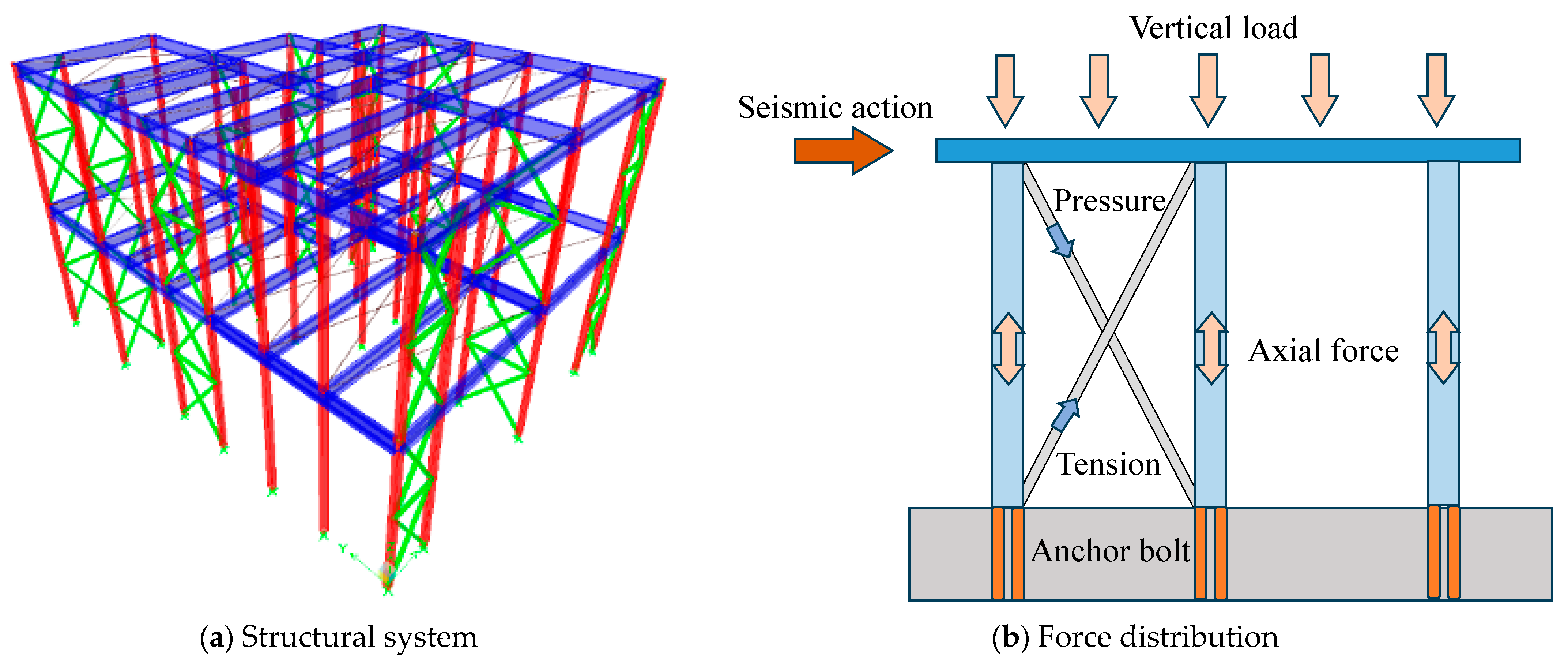
Figure 1. Steel structures with base-hinged columns.
Buildings 15 02881 g001
Figure 2. Detailed diagram of specimens (mm).
Buildings 15 02881 g002
Figure 3. Schematic of the joint connection.
Buildings 15 02881 g003
Figure 4. Loading schematic.
Buildings 15 02881 g004
Figure 5. Loading protocol.
Buildings 15 02881 g005
Figure 6. Failure characteristics of the RBF.
Buildings 15 02881 g006
Figure 7. Failure characteristics of the FBF.
Buildings 15 02881 g007
Figure 8. Hysteresis curves.
Buildings 15 02881 g008
Figure 9. Skeleton curve.
Buildings 15 02881 g009
Figure 10. Strength at the same loading displacement.
Buildings 15 02881 g010
Figure 11. Overall strength.
Buildings 15 02881 g011
Figure 12. Stiffness.
Buildings 15 02881 g012
Figure 13. Enclosed area of the hysteresis loop.
Buildings 15 02881 g013
Figure 14. Energy dissipation.
Buildings 15 02881 g014
Figure 15. Constitutive model.
Buildings 15 02881 g015
Figure 16. Finite element model.
Buildings 15 02881 g016
Figure 17. Failure mode.
Buildings 15 02881 g017
Table 1. Mechanical properties of steel.
SpecimenYield Strength fy
/MPa
Tensile Strength fu
/MPa
Modulus of Elasticity E 105 MPaElongation δ
/%
Diagonal brace368.12435.21192.8521.93
Column390.03444.44209.1424.97
Beam flange284.81415.00207.3738.58
Beam web249.28430.04209.3041.19
Horizontal tie rod276.45417.71213.9845.63
Flexible tension rod405.45509.22210.38222.5
Table 2. Load characteristic values.
SpecimenDirectionΔy/mmPy/kNΔmax/mmPmax/kNΔu/mmPu/kNμ
FW1Positive32.3941.3648.5559.8859.8650.901.85
Negative−27.00−38.29−45.39−47.28−56.93−40.192.11
FW4Positive45.9921.53146.341.35160.7235.153.49
Negative−48.16−22.19−118.10−35.92−140.3−32.312.91
Note: Δy and Py represent the yield displacement and yield load, respectively. Δmax and Pmax represent the peak displacement and peak load, respectively. Δu and Pu represent the ultimate displacement and ultimate load, respectively. μ represents the ductility, which is the ratio of Δu to Δy.
Table 3. Comparison of characteristic values.
SpecimenDirectionΔy/mmPy/kNΔmax/mmPmax/kNΔu/mmPu/kN
TestFEMTestFEMTestFEMTestFEMTestFEMTestFEM
RBFPositive32.421.641.458.748.651.259.960.259.965.450.952.3
Negative−27.0−21.6−38.3−58.7−45.4−51.2−47.3−60.2−56.9−65.4−40.2−52.3
FBFPositive46.028.721.524.3146.3132.541.436.2160.7164.935.232.1
Negative−48.2−28.7−22.2−24.3−118.1−132.5−35.9−36.2−140.3−164.9−32.3−32.1
Disclaimer/Publisher’s Note: The statements, opinions and data contained in all publications are solely those of the individual author(s) and contributor(s) and not of MDPI and/or the editor(s). MDPI and/or the editor(s) disclaim responsibility for any injury to people or property resulting from any ideas, methods, instructions or products referred to in the content.