Article

Investigating Three-Dimensional Auxetic Structural Responses to Impact Loading with the Generalized Interpolation Material Point Method

by
Xiatian Zhuang
1,
Yu-Chen Su
2 and
Zhen Chen
1,*
1
Department of Civil & Environmental Engineering, University of Missouri, Columbia, MO 65211, USA
2
Department Civil Engineering, National Central University, Taoyuan City 320, Taiwan
*
Author to whom correspondence should be addressed.
Buildings 2025, 15(16), 2878; https://doi.org/10.3390/buildings15162878
Submission received: 31 May 2025 / Revised: 10 August 2025 / Accepted: 13 August 2025 / Published: 14 August 2025
(This article belongs to the Special Issue Extreme Performance of Composite and Protective Structures)

Abstract

Understanding three-dimensional (3D) auxetic structural responses to impact loading remains challenging due to large deformations involving failure evolution and the interaction between geometric and material instabilities. In this study, the Generalized Interpolation Material Point Method (GIMP) is used to investigate representative auxetic structures, with the focus on the negative Poisson’s ratio effect on the responses to impact loading. Using a cubic lattice model for 3D re-entrant structures, simulations with different impact speeds are performed to evaluate corresponding energy absorption characteristics and deformation behaviors. Three constitutive models for lattice materials (linear elasticity, elastoplasticity, and damage) are employed to analyze the corresponding variations in auxetic structural performance. The computational results indicate that distinct deformation mechanisms are mainly associated with microstructural geometry, while the constitutive modeling effect is not significant. The findings demonstrate the importance of the process–structure–property relationship in the impact performance of protective structures. Verification against theoretical predictions of the Poisson’s ratio–strain relationship confirms the potential of GIMP in effectively engineering auxetic structures for general applications.

1. Introduction

Auxetic materials are a unique class of materials that exhibit an unusual mechanical property. They expand laterally when stretched and contract laterally when compressed, contrary to conventional materials. This behavior is characterized by a negative Poisson’s ratio (NPR), namely, the auxetic materials become thicker perpendicular to the loading axis under uniaxial tension. Based on the process–structure–property relationships for composite designs, both auxetic materials and structures exhibit NPR. Usually, auxetic materials refer to the macroscopic level, while auxetic structures (also called metamaterials) are characterized by their internal geometry and architecture at the micro- or meso-scale.
This counterintuitive property of NPR leads to a large shear modulus and improvement in hardness, energy absorption, and fracture toughness. These characteristics enable the applications of auxetic materials and structures in various fields, such as impact-resistant fabrication, medical implants, advanced aerospace structures, and sports apparel [1]. For impact resistance, auxetic materials are fabricated in lightweight protective devices, including helmets, body armor, and padding [2]. For medical implants, several kinds of tissue scaffolds and cardiac patches are designed with auxetic structures [3]. In aerospace engineering, auxetic structures are incorporated into aircraft components, including curved body parts and wing panels, due to their high shear modulus [4]. These diverse applications highlight the versatility and transformative potential of auxetic materials and structures in engineering and design innovation.
Based on their unique mechanical properties, much research and development on auxetic materials and structures have been conducted over the last several decades. These efforts demonstrate that if a material is composed of certain specialized cellular structures, it will exhibit auxetic behavior. The dynamic response and energy absorption under impact loading have been key areas of research on the use of NPR. One of the most common structure types exhibiting auxetic behavior is re-entrant honeycomb, as shown in a review article [5]. To investigate the re-entrant honeycomb structures, a series of model-based simulations has been performed using the finite element method (FEM). A recent study illustrated that the re-entrant structure could dissipate or absorb more kinetic energy than the non-auxetic structure [6].
Faraci et al. demonstrated a significant reduction in force and stress induced by a rigid ball impact, and the corresponding results are useful in the design of wearable protective devices, such as facial protectors [7]. These characteristics of energy absorption and force reduction make the auxetic materials with re-entrant structures suitable for applications in the aircraft industry to improve crashworthiness [8]. Furthermore, a new type of material incorporating a hierarchical re-entrant honeycomb structure has been developed, using the FEM [9], with improved impact resistance. Since the three-dimensional (3D) configurations of the re-entrant honeycomb structure are complex and difficult to fabricate using conventional techniques, additive manufacturing, commonly known as 3D printing, has been used to produce real samples. Compression experiments have been conducted on these samples to investigate the dynamic performance of the 3D re-entrant structure [10,11].
Recent experimental investigations now provide a rich empirical benchmark for validating numerical predictions of auxetic lattices. Compression and tension tests on 3D-printed re-entrant cells have recorded strain-dependent Poisson’s ratios as low as –5, alongside strut-bending failure sequences that govern the auxetic response [12]. Laser-clad metallic honeycombs and FDM-fabricated polymer lattices further reveal plateau stresses, energy absorption efficiencies, and progressive cell collapse or buckling modes under quasi-static crushing and low-velocity impact [13,14,15]. Meanwhile, tensile/compression characterization of PLA auxetic grids, corroborated by finite-element analysis, confirms negative Poisson’s ratios down to –0.8 and details crack initiation pathways [16].
As shown in previous studies [11,17,18,19,20,21], the mechanical characteristics of auxetic materials with re-entrant honeycomb structures are commonly investigated numerically using the FEM, which is one of the representative mesh-based methods. However, mesh-based methods have certain limitations in the balance between numerical accuracy and efficiency. First, the complex geometry of auxetic materials makes it challenging to generate a mesh with uniform elements, leading to a model with highly variable element sizes. As a result, the integration time step must be sufficiently small to ensure the convergence of numerical solutions. Second, the intricate geometry also increases the difficulty of maintaining fixed mesh connectivity in large-deformation analyses. Especially, severe mesh distortions can occur in simulating failure evolution with the use of conventional mesh-based methods. To overcome the above limitations, various meshless methods and particle-based approaches have been developed over the past several decades. These meshless and particle methods have been verified and validated in many engineering problems that were previously solved using mesh-based methods. However, numerical investigations of the mechanical behaviors of auxetic materials using meshless and particle methods remain sparse. In other words, there is a lack of verification and validation for meshless and particle methods in this specific research area. Therefore, this paper aims to verify and demonstrate the capability of a continuum-based particle method, namely, the Material Point Method (MPM), in simulating auxetic structural responses to dynamic loading.
The MPM employs the same weak formulation of the governing equations as in the FEM [22]. It combines the strengths of both Lagrangian and Eulerian methods so that computational fluid dynamics and solid dynamics could be simulated in a single computational domain with multi-phase (solid–liquid–gas) interactions. The MPM spatially discretizes the continuum body into a finite set of material points, which can be considered as mass particles rather than volume elements in 3D cases. Hence, mass conservation is inherent in the MPM. With this particle-based approach, material points can move freely without the need for mesh connectivity, thereby automatically avoiding the issues related to non-uniform elements and fixed mesh connectivity in the FEM. In addition, a set of arbitrary background grids is employed to cover the entire computational domain, and a mapping procedure is used between the material points and grid nodes to evaluate divergence and gradient operators. The background grids are used to solve the governing equations instead of using the material points. Due to the above unique features, the MPM has been widely applied to engineering problems involving large deformations, failure evolution, complex geometries, and multi-phase interactions [22,23,24,25,26,27,28]. However, the original MPM could induce cell-crossing errors due to the use of a single-cell-based mapping operation between material points and background grid nodes. To eliminate these errors, several improved versions have been developed to reduce or eliminate the cell-crossing errors with additional computational expenses [22]. Among these improved versions, the Generalized Interpolation Material Point Method (GIMP) is a representative approach that adopts a particle-based mapping operation for providing a nonlocal support spanning several cells surrounding the material point of interest [29]. To keep the balance between computational accuracy and efficiency, the GIMP is employed in this work to investigate the mechanical behaviors of auxetic materials, which could reduce the cell-crossing errors with the least computational expense compared with other MPM variants.
In the remaining sections of this paper, a 3D cubic model with a re-entrant honeycomb structure is designed, and a series of low-speed and high-speed impact simulations are performed using the GIMP with linear elasticity, elastoplasticity, and damage models for lattice materials, respectively. The NPR and constituent effects on the auxetic structural responses to impact loading are then investigated with respect to energy absorption mechanisms.
The 3D computational model allows bending, contact, and breakage of re-entrant auxetic lattices. Changing the ligament angle shows that the model could predict negative Poisson’s ratios. Comparing the computational results against theoretical ones verifies the proposed procedure. Identifying the differences between auxetic structural responses and corresponding solid ones to impact loading demonstrates the shock-absorbing capability of the computational model. The above findings will be detailed below.

2. NPR Modeling and Simulation Methodology

2.1. NPR Modeling with Re-Entrant Honeycomb Structures

Based on previous studies of NPR materials with re-entrant honeycomb structures, several re-entrant unit cells arranged periodically can exhibit NPR characteristics. A representative two-dimensional model of a unit cell is shown in Figure 1a. By assembling two vertically crossed honeycomb structures, a 3D unit cell model can be established, as demonstrated in Figure 1b. The resulting structure is a generalized form of a 3D honeycomb cell, acting as the 3D equivalent of the classic re-entrant honeycomb. Geometric and material parameters of the unit cell govern the mechanical performance of the structure. These governing parameters include the thickness of cell wall (t), the depth of cell wall (w), the angle between the oblique line and the vertical line (θ), the length of the horizontal beam (h), the length of the oblique line of the cell (l), the elastic modulus of structural material ( E s ), and the equivalent elastic modulus ( E R , 3 D ) . Note that only four of the five geometric parameters are independent, and isotropic linear elasticity has two independent material constants. Based on the previous work [8], the equivalent elastic modulus of a single, uniform 3D unit can then be expressed as
E R , 3 D = ( t l ) 3 2 E s w c o s θ l ( h l s i n θ ) 2 s i n 2 θ
and the corresponding Poisson’s ratio can be found to be
υ 3 D = c o s 2 θ h l s i n θ s i n θ
As a result, the system responses depend on four geometric parameters and two material constants for isotropic linear elasticity.

2.2. Simulation Methodology with the GIMP

To be complete, the simulation methodology with the GIMP and the difference between the MPM and GIMP are briefly described below, without the details as provided in [22]. The strong and weak forms of the governing equation for both the MPM and GIMP are based on the conservation of linear momentum for isothermal cases, as expressed in Equations (3) and (4) as follows:
ρ a = · σ + ρ b
Ω ρ a w d Ω = Ω σ : w d Ω + Γ σ τ ¯ w d Γ + Ω ρ b w d Ω
In Equations (3) and (4), ρ = ρ ( x , t ) is the mass density, a x , t is the acceleration vector, σ ( x , t ) is the Cauchy stress tensor, and b ( x , t ) represents the body force, such as that due to gravity. The x denotes the time-dependent position vector of each material point in a continuum body. In addition, w is the test function, τ - is the specific traction vector, Ω is the configuration of the continuum body, and Γ σ is the part of the boundary with a prescribed traction. As mentioned in Section 1, the MPM discretizes a continuum into a finite number of material points (mass particles) so that Equation (4) can be rewritten as follows:
p = 1 N p M p w x p t a x p t =                                                                                                                                   p = 1 N p σ p ( x p t ) : w | x p t + M p w ( x p t ) b ( x p t ) + Γ σ w ( x p t ) τ - d Γ
in which the N p and subscript p that is 1 ,   2 ,   3 ,   ,   N p represent the total number and identification of material points for the specific continuum body, respectively. The t indicates the current time, with an explicit time integration scheme being used here. As a result, M p and x p t represent the mass and the position vector for a material point p at time t, such that the conservation of mass is inherent in the MPM.
In the MPM simulation framework, the material points are distributed in a series of background grid cells, and Equation (5) is solved on the cell nodes. Therefore, a nodal basis function is used for the mapping operations between material points and corresponding cell nodes. As a result, Equation (5) can be rewritten in terms of the background grid cells and their corresponding nodal basis functions, namely
p = 1 N p M p a x p t N i x p t =                                                                                                                                             p = 1 N p M p ρ p t σ p t : N i ( x p t ) + p = 1 N p M p N i x p t b p + Γ σ N i ( x p t ) τ - d Γ
Different from the subscript p in Equation (5), the subscript i in Equation (6) represents the identification for each background grid node, and N i ( x p t ) and N i ( x p t ) are the nodal basis function value and its corresponding gradient one at the position vector for material point x p t . The mass and stress tensor of each material point are mapped from itself to the corresponding background cell nodes via the nodal basis functions in the MPM mapping operation. In the original MPM, a linear function defined over a single cell in the background grid is utilized as the nodal basis function. However, this linear nodal basis function would yield discontinuous gradients ( N i ( x p t ) in Equation (6)), leading to numerical errors, when the material points pass through the cell boundaries. These errors are known as cell-crossing errors. To eliminate these errors, the single-cell-based mapping operation in the original MPM is replaced by a particle-based mapping approach referred to as the GIMP [29]. As each material point represents a continuum volume element, its deformation may extend across multiple neighboring cells rather than being restricted to a single cell containing the material point. Consequently, the nonlocal nature of the mapping operation depends on the order of the nodal basis functions and incurs additional computational costs as compared with the original MPM. To keep the balance between accuracy and efficiency, the improved GIMP [30,31,32] is used below for the computational study.

3. Computational Setting

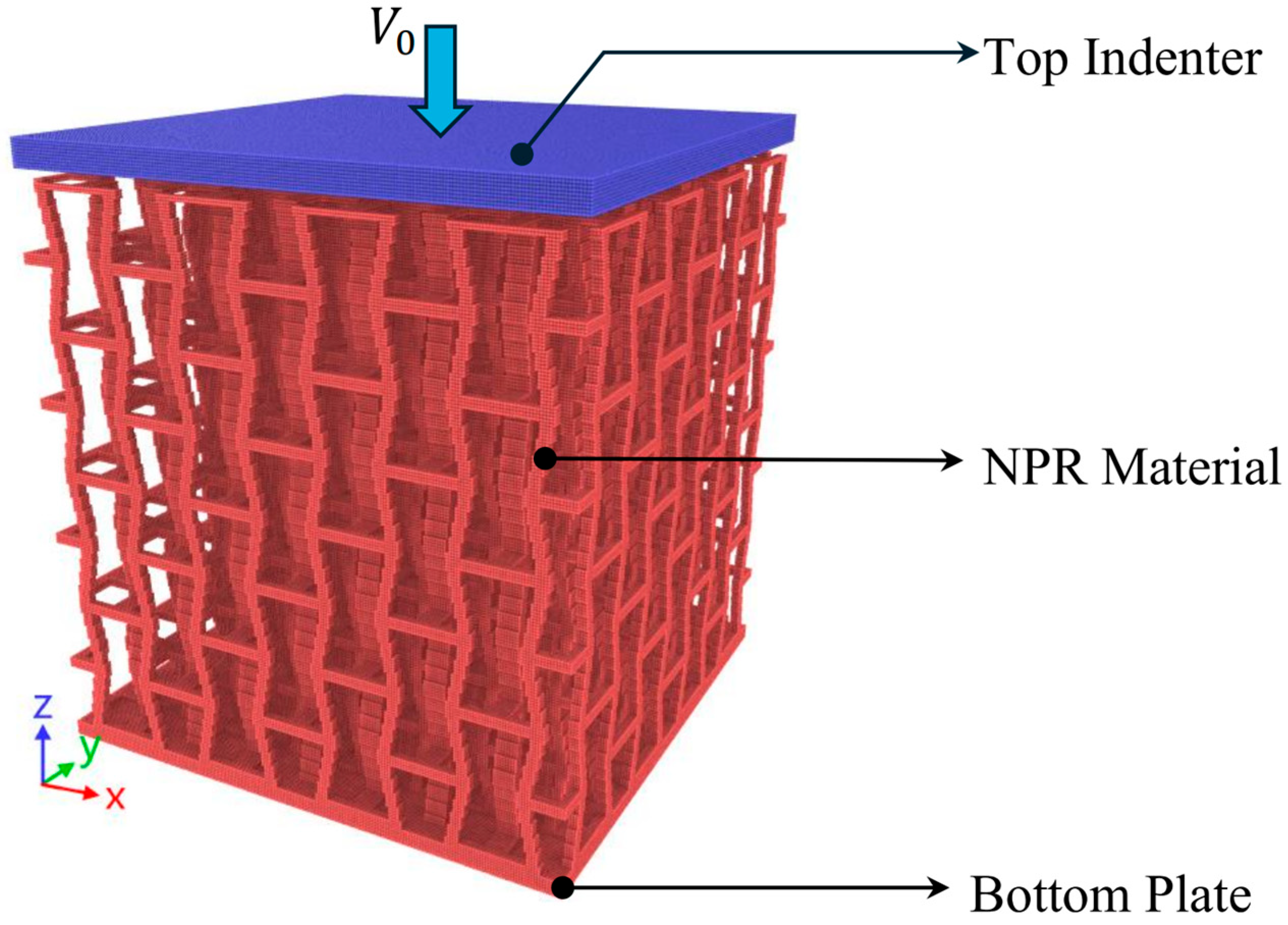
The 3D computational model consists of a honeycomb re-entrant lattice structure, a bottom layer plate, and a top indenter, which is discretized with the GIMP, as shown in Figure 2. In Figure 2, the top indenter and bottom plate are represented by blue and red material points, respectively. The NPR structure covers the GIMP unit cubic cells, with each unit cell containing eight material points, for which the 3D cell size in each direction can be set to any value, depending on the user’s requirement.
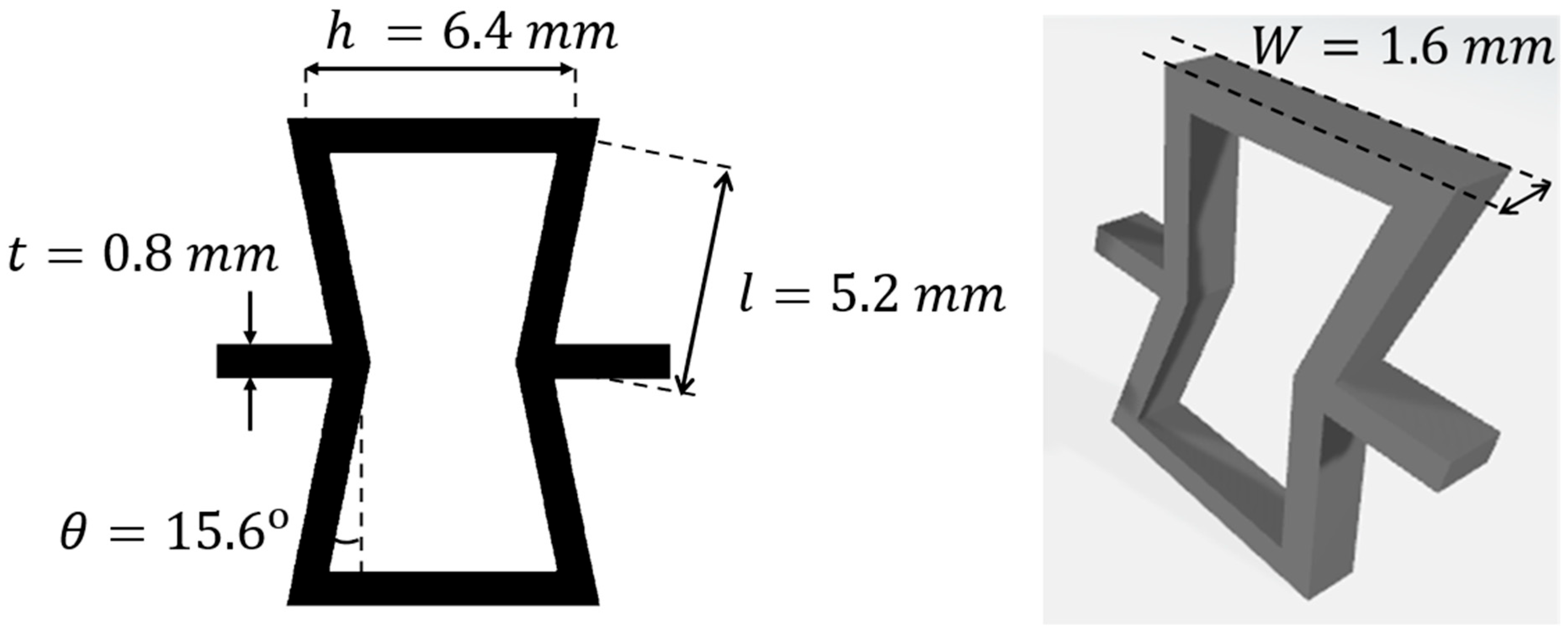
Taking a further look at this computational model, the NPR lattice structure is composed of 64 unit cells, arranged as four cells in each direction. The detailed geometrical settings are demonstrated in Figure 3. As a result, the overall dimension of the 3D NPR lattice structure is 40 mm × 40 mm × 40 mm. The areas of both the top indenter and the bottom plate are 40 mm × 40 mm, respectively. Additionally, the thicknesses of the two sections are both 1.6 mm. For verifying the equivalent Poisson’s ratio, the top indenter will move downward at a velocity of 2 m/s to simulate the compression test. Finally, aluminum, with an elastic modulus of 65.76 GPa and Poisson’s ratio of 0.3, is chosen for the structural material in the computational model.
To investigate the constituent effect on the system response, three types of material models for aluminum are used in this study, namely, linear elasticity, elastoplasticity, and damage models, based on the previous work on model-based simulation of failure evolution in composite responses to impact loading [33]. Simulation results associated with different constitutive models are compared to explore the influence of constitutive modeling on the system responses. In the elastoplasticity model, the uniaxial stress–strain relation is shown in Figure 4a, and the von Mises yield criterion for aluminum is applied to update the stress tensor. The elastoplasticity model combined with a damage criterion is illustrated in Figure 4b, where the material is considered to fail once the equivalent stress reaches a prescribed fracture stress. In both Figure 4a and Figure 4b, the yield stress for aluminum is set as 102 MPa. Additionally, the fracture stress in the damage criterion is chosen to be 148 MPa. Johnson–Cook material and damage constants for Al 1100-H12 are used by Mohammad et al. in thin-plate ballistic studies [34].
All simulations were executed with our in-house three-dimensional GIMP code. The simulation ran on a single-socket Intel Core i9-13900K workstation (24 cores/32 threads: 8 P-cores up to 5.6 GHz and 16 E-cores up to 4.3 GHz) equipped with 64 GB of DDR5-5600 RAM and running Ubuntu 22.04. The stable time increment was chosen automatically from the Courant–Friedrichs–Lewy (CFL) criterion.

4. Verification of NPR

4.1. Convergence Study

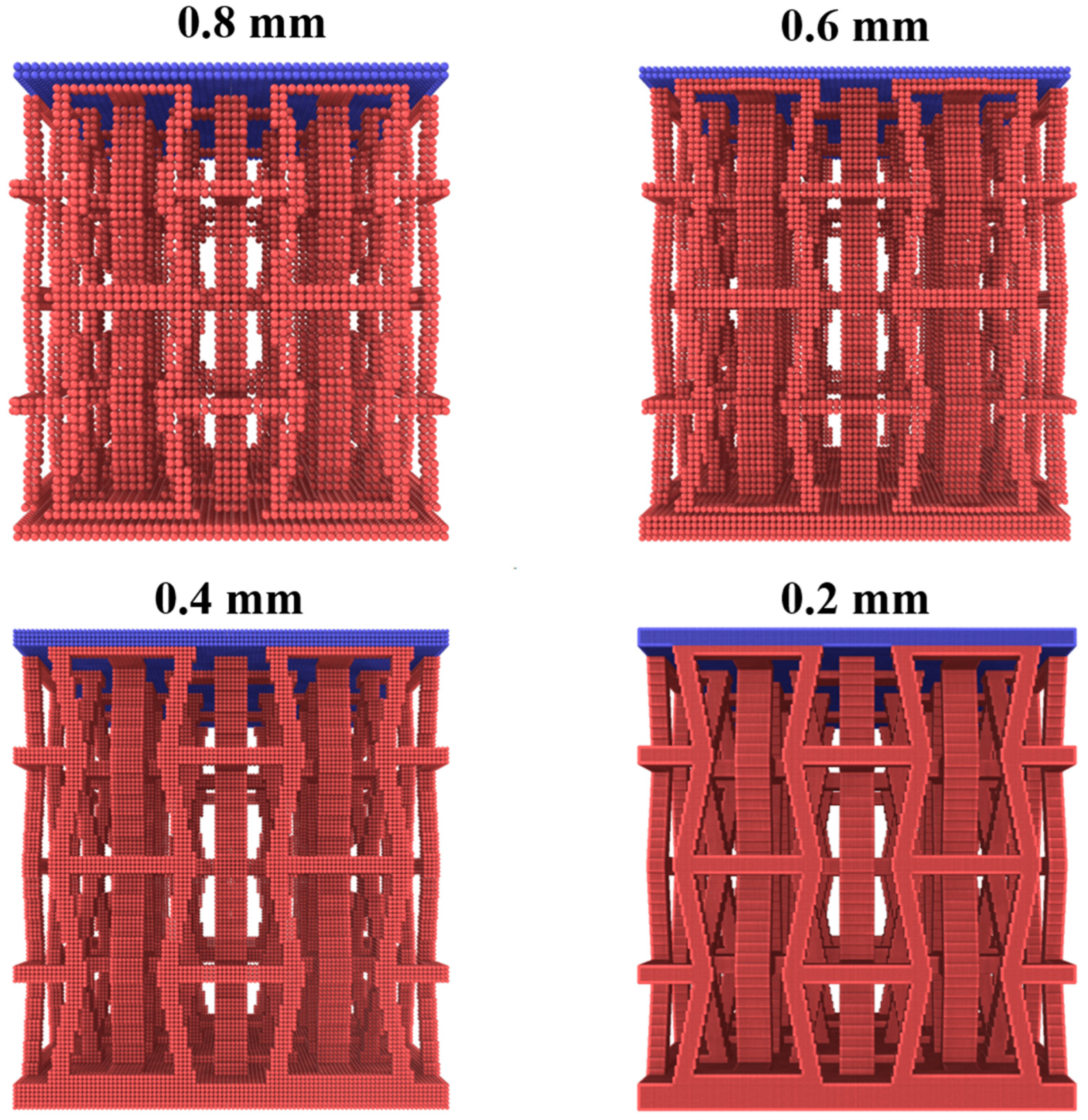
Since the cell size of the MPM background grid affects the simulation accuracy, a convergence study is performed in terms of cell size. Using isotropic linear elasticity, a scaled-down numerical model is established to reduce computational cost. Specifically, the NPR material is scaled down to a cube with dimensions of 20 mm × 20 mm × 20 mm, and four different cell sizes (0.2 mm, 0.4 mm, 0.6 mm, and 0.8 mm) are utilized to assess the influence of mesh refinement on the calculated Poisson’s ratio. As the mesh is refined, the total number of material points increases substantially, resulting in higher computational costs associated with finer grids. For instance, the model with a 0.8 mm cell size contains approximately 32,000 material points. In comparison, the cell sizes of 0.6 mm, 0.4 mm, and 0.2 mm result in approximately 8.1 × 10 4 , 2.5 × 10 5 , and 2.0 × 10 6 material points, respectively, as illustrated in Figure 5.
For calculating the Poisson’s ratio with the use of GIMP, the top indenter moves downward with a velocity of 2.0 m/s to simulate a uniaxial compression process. During the compression process, both axial and transverse deformations are recorded to compute Poisson’s ratio. The undeformed and deformed configurations for the four different cell sizes are illustrated in Figure 6, where the bottom row represents the NPR material under a compression displacement of 0.4 mm. This figure shows that the deformation pattern with the largest cell size (0.8 mm) differs significantly from those with smaller cell sizes. The contraction behavior in the 0.8 mm model is less pronounced than in the others, indicating that fewer material points result in lower accuracy when describing the deformation behavior, especially in the lateral contraction under compression.
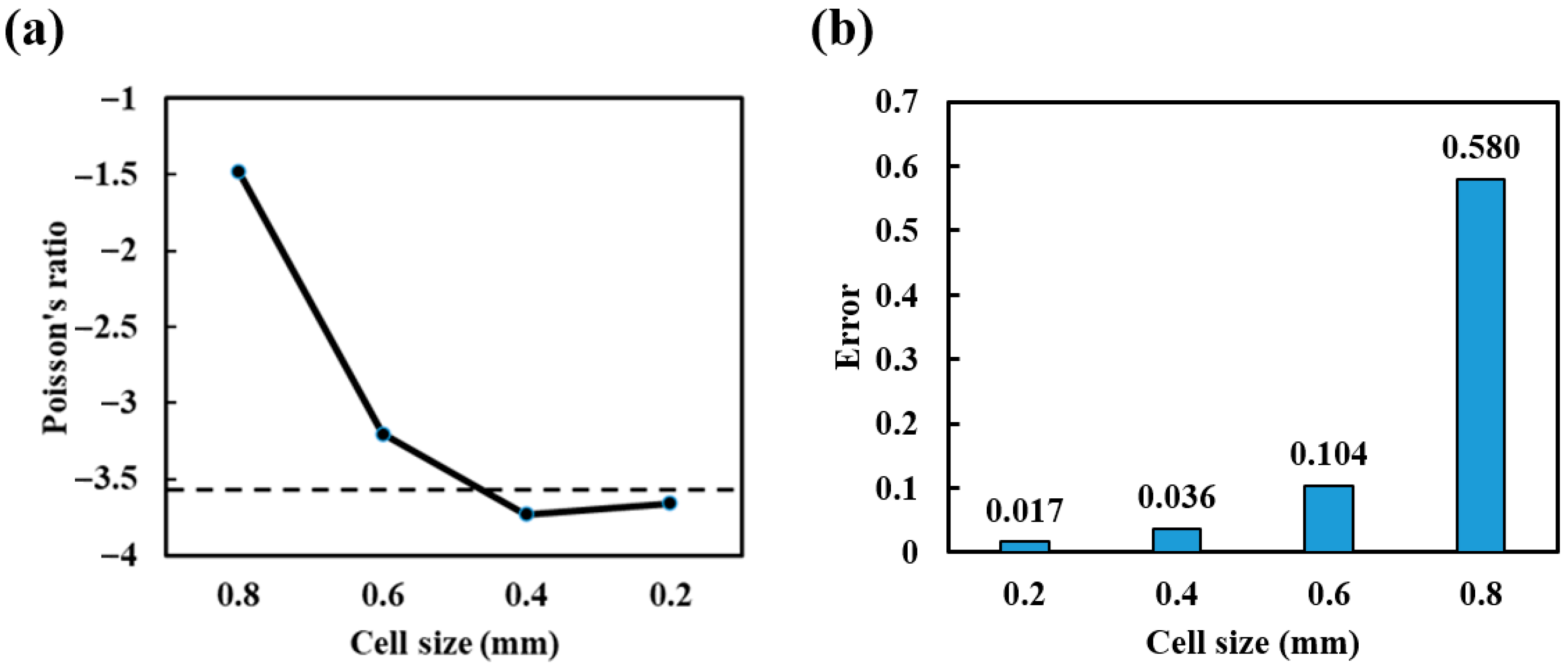
Based on Equation (2) and the corresponding geometrical parameters of the NPR unit cell, the equivalent Poisson’s ratio is approximately −3.57. The simulated values of Poisson’s ratio are summarized in Figure 7, for which the Poisson’s ratio is calculated by dividing the maximum lateral contraction by the vertical compression displacement. Since both the lateral contraction and vertical compression are negative, a negative sign is added to the simulated Poisson’s ratio to be consistent with Equation (2). As shown in Figure 7, the Poisson’s ratio with a cell size of 0.8 mm is significantly different from the analytical value by Equation (2), meaning that the transverse deformation in this case is much smaller than in other cases. This result aligns with the deformation patterns, as shown in Figure 6. Hence, Figure 6 and Figure 7 demonstrate that coarse grids (0.8 mm and 0.6 mm) are less capable of accurately capturing the mechanical behavior of the NPR model. In contrast, the GIMP grids with cell sizes of 0.2 mm and 0.4 mm exhibit reasonable accuracy. The convergence study thus indicates that further refinement beyond 0.4 mm yields no significant improvement in accuracy. Hence, to keep the balance between computational accuracy and efficiency, a cell size of 0.4 mm is chosen for the remaining simulations in this work.

4.2. Verification of NPR with Different Angles

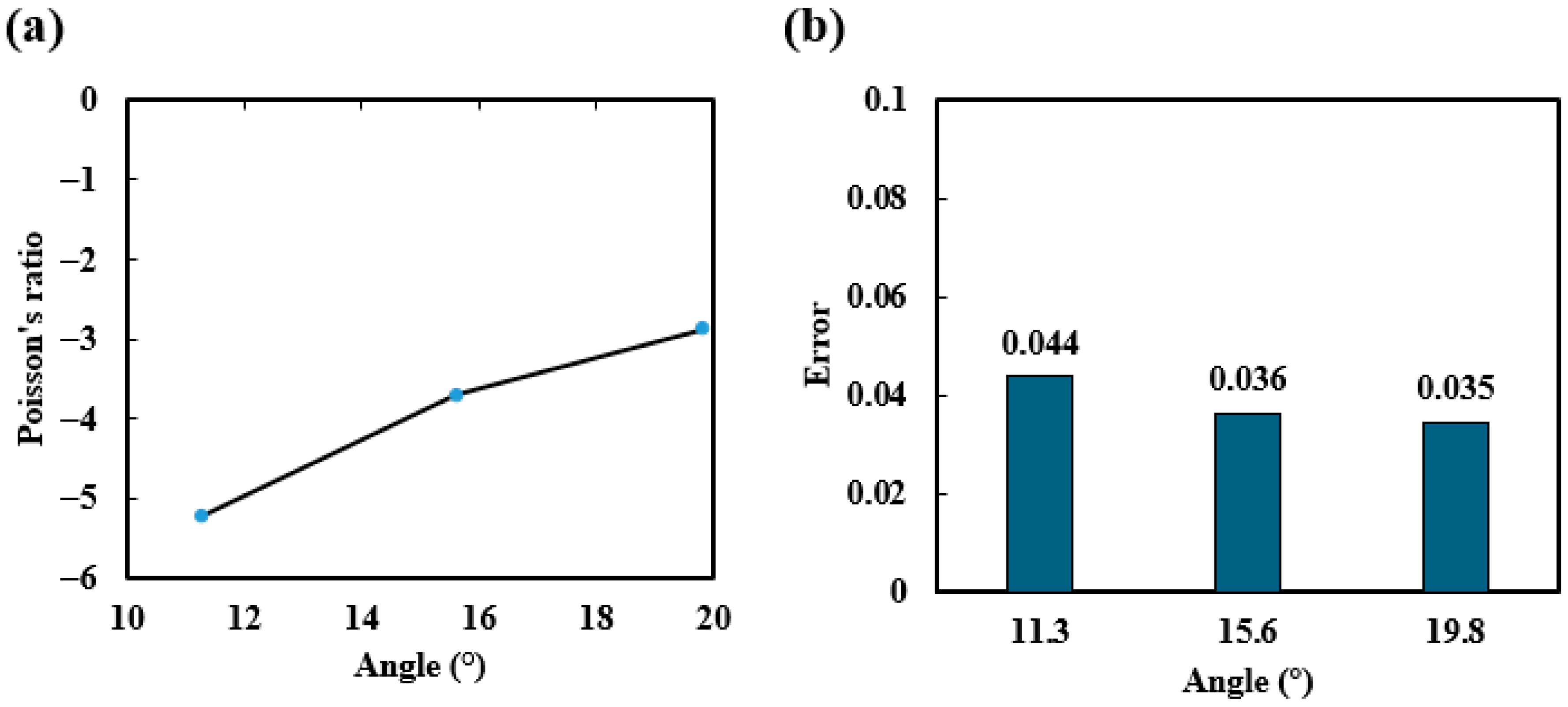
To verify the sensitivity of the auxetic response to ligament inclination, we performed a targeted parametric sweep on the validated 20 mm × 20 mm representative cell. Only the horizontal beam h was adjusted to 6.0, 6.4, and 6.8 mm, while the vertical height was held constant at 10 mm, and all material properties and boundary conditions matched those in Section 4.1. Applying different lengths of horizontal beam (h), θ can be found as 11.3°, 15.6°, 19.8°, respectively. For each configuration, uniaxial compression was simulated using the same GIMP time-integration scheme and mesh density adopted in our earlier convergence study. The analytical prediction based on Equation (2) was −5, −3.59, and 2.77 for θ = 11.3°, 15.6°, 19.8°, respectively. Figure 8b shows this comparison by plotting both the calculated and simulated NPR against θ and superimposing the absolute error as a secondary ordinate. The accompanying error plot in panel (b) indicates that the GIMP results deviate from the analytical values by less than 0.045 across the entire range. Practically, these data suggest that even modest reductions in angle (≲0.05) can yield sizeable gains in auxetic response without altering material or cell density. Conversely, the diminishing slope at larger angles warns that further increases will quickly erode the auxetic effect.
This confirms that the re-entrant angle is an effective design parameter for influencing deformation shape without adversely affecting stiffness. The verified sensitivity study, therefore, provides both a quantitative benchmark for future experimental comparison and a validated guideline for geometry optimization.

4.3. Verification of NPR with a Larger Model

In the previous subsection, a scaled-down model with dimensions of 20 mm × 20 mm × 20 mm was used in the convergence study in terms of cell size. Using the cell size of 0.4 mm, a larger model with the dimensions of 40 mm × 40 mm × 40 mm is used in this subsection to further verify the GIMP for simulating the NPR effect on the system response. All other parameters remain the same as those in the smaller model.
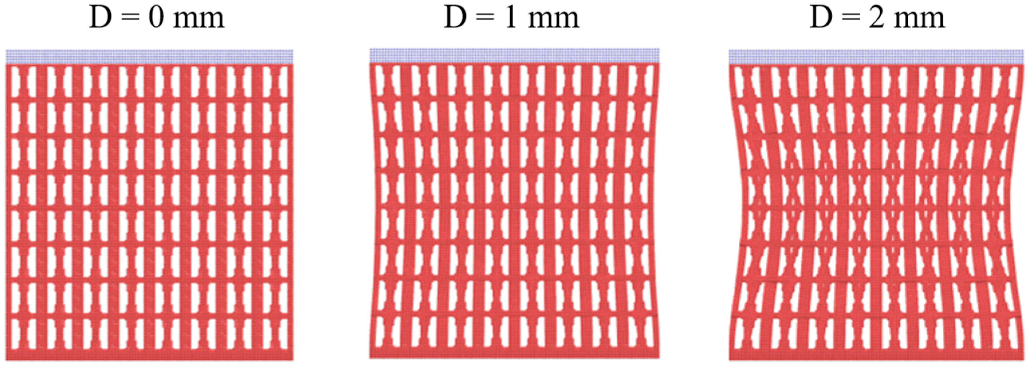
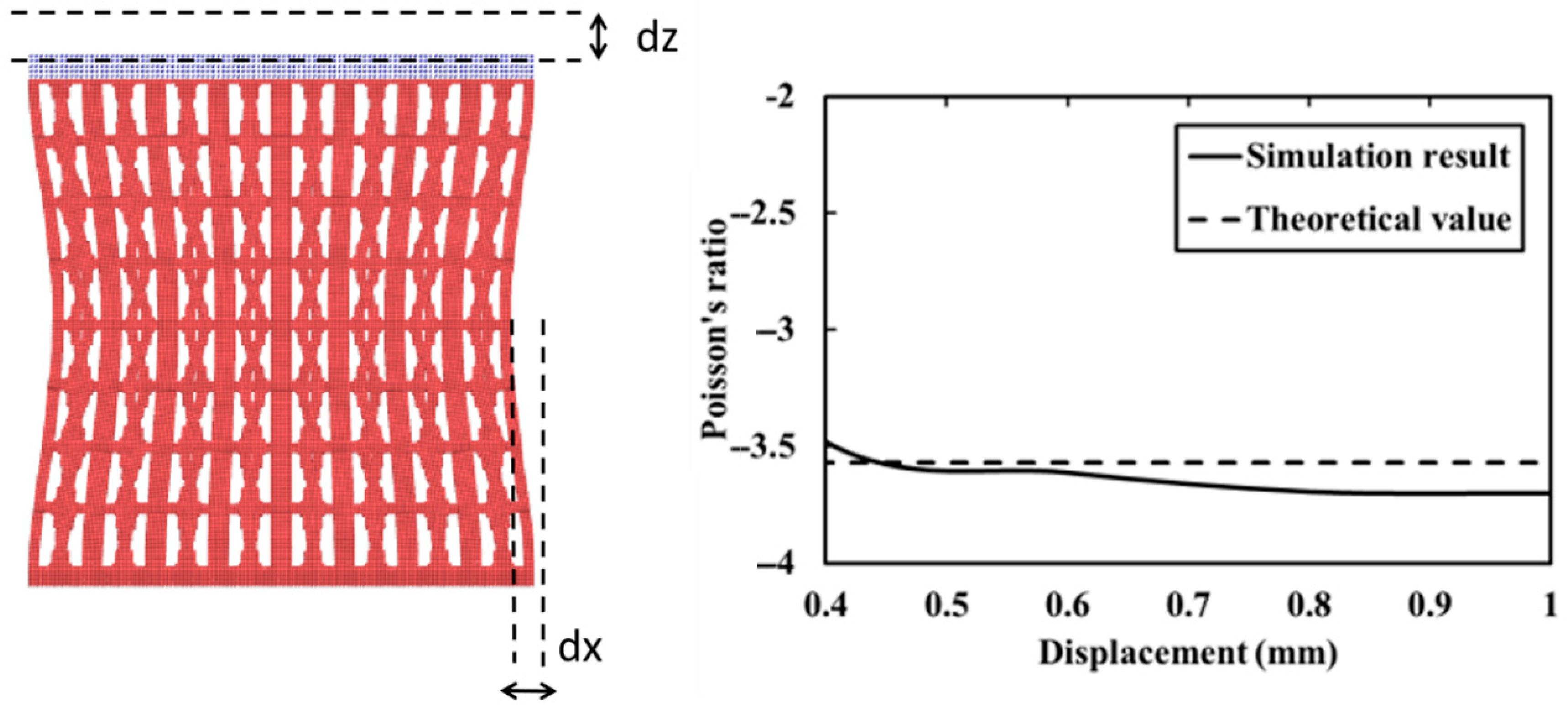
During the compression process, the deformation patterns with different displacements are shown in Figure 9. Additionally, Poisson’s ratio has been continuously evaluated throughout the entire compression process. The relationship between Poisson’s ratio and displacement is illustrated in Figure 10. It could be observed that the simulated Poisson’s ratio closely matches the theoretical value when the displacement is less than 0.6 mm, which is consistent with the findings for a smaller model. Hence, the NPR effect could be objectively simulated with the GIMP, whether the model size is small or large. When the displacement is beyond 0.6 mm, the difference between the theoretical and numerical results increases, indicating the onset of inelasticity as discussed next.

5. Constitutive Effect

5.1. Comparison of Failure Evolution Patterns

As shown above, the increase in top-plate displacement results in inelasticity. To investigate the inelastic effects, two constitutive models are employed, namely, elastoplasticity and elastoplasticity combined with damage, as demonstrated in Figure 4 and described in Section 3. Based on these constitutive models, load–displacement curves and distributions of equivalent plastic strains and damaged (failure) material points are used here for describing the details of deformation behaviors with the NPR effect.
Figure 11 and Figure 12 show the distributions of equivalent plastic strains and damaged material points, respectively. As can be seen from these figures, larger equivalent plastic strains and failure zones are concentrated in similar regions, particularly at the joints between horizontal and oblique members. This phenomenon indicates that the special joint design could induce an obvious lateral contraction under compression. Additionally, larger equivalent plastic strains and failure zones are more concentrated in the upper half than in the lower half of the NPR model. It is because the deformations propagate gradually from the top indenter to the bottom. Figure 11 and Figure 12 also reveal that high stress concentrations occur particularly in the narrowing areas of the hourglass shape. These auxetic deformations and the resulting localization weaken the NPR material, further reducing its load-bearing capacity. Note that there is no geometric instability that can be observed from the figures, due to the aspect ratio employed in the GIMP model. Hence, the characteristics of energy absorption in the provided NPR material are mainly related to the strain localization (material instability), as in conventional composite materials under impact loading [28]. Certainly, Equation (2) is not valid when strain localization occurs, as demonstrated in Figure 11.

5.2. Verification of the Equivalent Elastic Modulus

As shown in Equation (1), the NPR material with this re-entrant honeycomb structure exhibits an equivalent elastic modulus by adopting the closed-form expression proposed by Wang et al. [8] for re-entrant lattices with a negative Poisson’s ratio. Using aluminum as the structural material and the corresponding geometric settings, the equivalent elastic modulus is calculated to be 1.90 GPa. To verify the capability of GIMP in predicting the equivalent elastic modulus, the average compressive stress and strain need to be recorded. However, complex geometry makes it difficult to accurately capture stress and strain at each instant. Therefore, the reaction load applied on the bottom plate, and the compressive displacement of the top indenter are utilized as an alternative to evaluate the stiffness in the load–displacement space. The total reaction load is calculated by multiplying the average z-component of the stress tensor on the bottom plate surface by its corresponding area in the x-y plane.
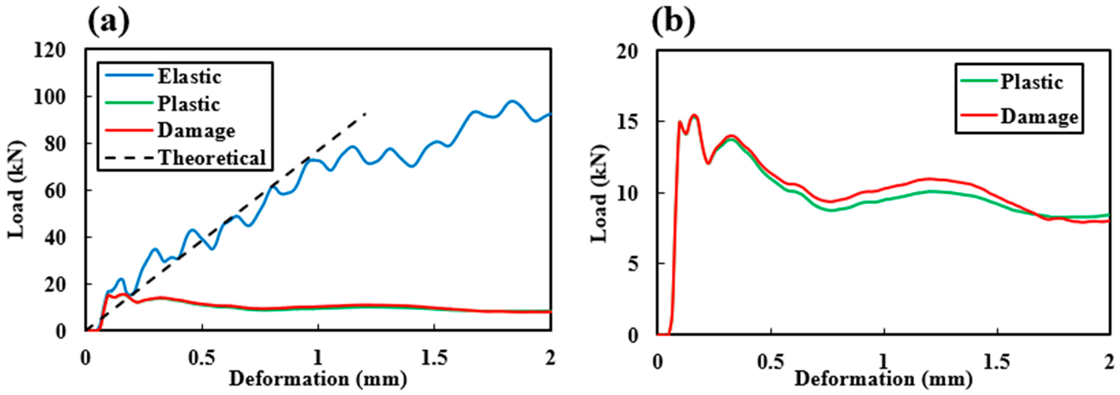
The load–displacement curves with the three constitutive models for lattice materials—elasticity, elastoplasticity, and elastoplasticity combined with damage—are plotted in Figure 13a. To verify the accuracy, a theoretical load–displacement curve based on Equation (1) is also shown in Figure 13a. As can be observed from Figure 13a, both simulated and theoretical curves exhibit an excellent agreement throughout the elastic deformation range. However, the elastic simulation results begin to deviate after the top-plate displacement is beyond 1 mm, showing a lower load level as compared to the theoretical result. This deviation might be attributed to the no-slip contact scheme inherent in the MPM/GIMP for evaluating lattice structural responses [29]. Furthermore, the oscillations in the simulated elastic curve could also be observed, with the oscillation frequency being decreased as contacts among lattice members occur. These oscillations mainly result from the wave interactions among the lattice members within the NPR model. As compared with the theoretical and GIMP curves with linear elasticity, the curves with elastoplasticity and damage models exhibit significantly lower load-level responses after the peak load is reached. In addition, the curves look smooth without obvious oscillations, which is due to the plastic effect on wave interactions among lattice members. However, the difference between these two inelastic models is not significant, as demonstrated in Figure 13b, which implies that the NPR lattice structure plays an important role in the system response, as compared with that of different inelastic constituents.

6. NPR Effect on Impact Resistance

To investigate the NPR effect on impact resistance, the downward velocity of the top indenter is increased from 2 m/s (via continuous input with time) to 500 m/s (via flyer impact, as demonstrated in Figure 14). It means that the impact velocity is only applied in the first timestep. The dimension of the NPR model is 40 mm × 40 mm × 40 mm, which is the same as the larger model in Section 4.2. The thicknesses of the top indenter and bottom plate both remain at 2 mm. Since the re-entrant honeycomb structures play a significant role in energy absorption and impact resistance, the reaction load history with time on the bottom layer is recorded throughout the entire impact simulation, as demonstrated in Figure 15. By analyzing the reaction load history and corresponding deformation patterns, the effect of NPR on the system response could be evaluated via a comparative study using a pure solid block, as shown in Figure 14 and Figure 15. Because the top plate (shown as the gray plate in Figure 14) is intended to move downward at the high impact speed rather than at a continuous low speed, it is referred to as a flyer rather than an indenter. Aside from the internal structure, all other settings in the pure solid block—including material properties, dimensions, and impact velocity—are identical to those in the NPR model. By comparing the reaction load histories of the two different models, the post-impact characteristics of the NPR material can be clearly assessed. Since the high-speed impact results in extremely large deformations, the elastoplastic constitutive model with the von Mises yielding criterion is adopted for structural material in this simulation. The 4 µs delay before the shock front reaches the bottom of the NPR specimen, compared with pure block, confirms that the re-entrant cells act as a lattice network: incident compressive waves repeatedly reflect and convert at ligament junctions, slowing the wave propagation relative to the solid block. This effect is similar to layered acoustic metamaterials in which local resonances and periodic discontinuities lengthen the effective propagation path. In addition, the peak compressive load on the NPR support is almost 70 times lower than that of the block, even though both specimens experience the same impact impulse. The attenuation of load arises mainly from the stepwise rotation and flexure of the re-entrant ligaments, which stretches energy absorption over a longer crush distance. The block, lacking such deformation degrees of freedom, must accommodate the impulse almost elastically. Consequently, it stores and then rapidly returns strain energy, producing a high-frequency stress spike. In the NPR lattice, the energy is instead siphoned into irreversible local bending and densification, which damps the outgoing wave.
Figure 16 shows that, although the auxetic lattice (NPR) and the solid aluminum block begin with nearly identical kinetic energies (around 1 kJ), their dissipation trajectories are fundamentally different. The block’s kinetic energy decreases to zero within the first 0.6 mm of penetration, signaling an almost instantaneous conversion of translational energy into internal strain energy and compressive shock waves. By contrast, the NPR curve decays smoothly and almost exponentially, retaining 10% of its initial energy until about 15 mm and reaching near zero only at 20 mm. Such an extended tail testifies to the sequential engagement of re-entrant rotation, cell-wall bending, and eventual densification, each activated at progressively larger strokes and thereby spreading the impact work over space and time. The two specimens ultimately absorb the same total work energy conservation is satisfied, but the auxetic lattice accomplishes this through controlled, low-force deformation, trading a modest increase in crush distance for a drastic reduction in peak load.
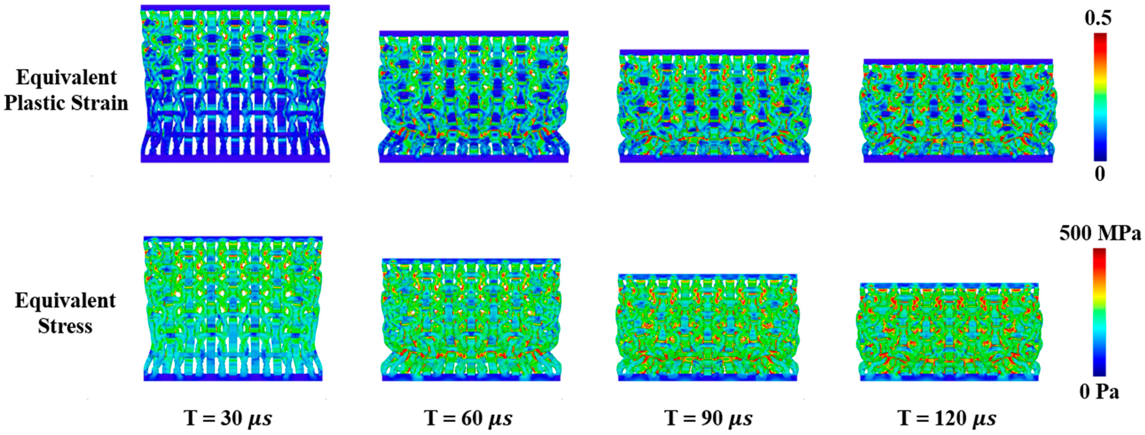
To observe the differences in the high-speed impact behaviors between the NPR material and pure solid block, the distributions of equivalent plastic strain and corresponding stress at specific time instants are demonstrated in Figure 17 and Figure 18, respectively. There are two main differences between the NPR and solid models. First, the equivalent plastic strains in the pure solid block are considerably smaller than those in the NPR model and are closer to the impact surface than the NPR model. This indicates that the NPR model could absorb much more impact energy before the bottom layer feels the impact than the solid model. However, the NPR effect will disappear with the increase in plastic strain distributions. Second, the stress level of the pure solid model is much higher at the bottom plate than the NPR model, which leads to a sudden increase in reaction load, as shown in Figure 15. In summary, the NPR model with its re-entrant honeycomb structures is effective in impact-resistant designs, and the GIMP could perform an objective evaluation of impact-resistance with different kinds of materials.

7. Conclusions

This work verifies and demonstrates the effectiveness of GIMP in evaluating the mechanical behaviors of the NPR materials with 3D re-entrant honeycomb structures under different loading conditions. The main findings from this investigation are summarized as follows:
  • The NPR, as obtained by using the GIMP [30,31], is consistent with the theoretical value [8]. Additionally, the convergence study with varying grid cell sizes not only verifies the results but also shows the fast convergence of numerical solutions.
  • Three different constitutive models for structural materials are adopted to investigate the constitutive effects on the failure evolution patterns and reaction load–displacement relations. Within the elastic range, the load–displacement relationship is linear and aligns with the analytical prediction. The inelastic models demonstrate that higher equivalent plastic strains and damaged material points are more concentrated at the joints between the horizontal and oblique lattice members. It indicates that the specially designed joints promote noticeable lateral contraction under compression. The difference between elastoplasticity and damage models for structural materials is not significant in governing the impact responses, which indicates the important role of process–structure–property relationships in impact-resistant composite designs.
  • Under high-speed impact, the NPR material transfers most of the impact kinetic energy into the re-entrant honeycomb structures. In contrast, the kinetic energy propagates through the solid block to the bottom plate. As a result, the NPR material significantly reduces the load transmitted to the bottom plate. The GIMP could effectively capture the impact resistance characteristics of the NPR materials with lattice structures.
Although the auxetic lattice exhibits clear advantages in energy absorption under dynamic loading conditions, the limited modeling choices considered here constrain the generality of the findings. First, the strain localization effect remains to be further investigated. Once damage starts, localization bands appear to be around the particle size because the damage model lacks non-local regularization in this work. Second, non-slip contact, as inherent in the MPM and GIMP, is assumed in this work. Because of this assumption, the energy dissipation in the contact zone and stress oscillations, as observed in the simulations, necessitate further study in combination with experimental efforts for both verification and validation. Nevertheless, both man-made [35] and nature-made [36,37] multiscale lattice or porous materials have great potential in advancing composite system designs against extreme loadings, for which the continuum-based particle method, MPM/GIMP, could be a robust simulation tool with further improvement.

Author Contributions

Conceptualization, X.Z. and Y.-C.S.; methodology, X.Z. and Y.-C.S.; software, X.Z.; validation, X.Z. and Y.-C.S.; formal analysis, X.Z.; investigation, X.Z.; resources, X.Z.; data curation, X.Z.; writing—original draft preparation, X.Z.; writing—review and editing, Y.-C.S.; visualization, X.Z.; supervision, Z.C.; project administration, Z.C. All authors have read and agreed to the published version of the manuscript.

Funding

This research received no external funding.

Data Availability Statement

The data presented in this study are available on request from the corresponding author.

Conflicts of Interest

The authors declare no conflict of interest.

References

  1. Duncan, O.; Shepherd, T.; Moroney, C.; Foster, L.; Venkatraman, P.D.; Winwood, K.; Allen, T.; Alderson, A. Review of Auxetic Materials for Sports Applications: Expanding Options in Comfort and Protection. Appl. Sci. 2018, 8, 941. [Google Scholar] [CrossRef]
  2. Madke, R.R.; Chowdhury, R. Anti-Impact Behavior of Auxetic Sandwich Structure with Braided Face Sheets and 3D Re-Entrant Cores. Compos. Struct. 2020, 236, 111838. [Google Scholar] [CrossRef]
  3. Kim, Y.; Son, K.; Lee, J. Auxetic Structures for Tissue Engineering Scaffolds and Biomedical Devices. Materials 2021, 14, 6821. [Google Scholar] [CrossRef] [PubMed]
  4. Wang, Z.; Zulifqar, A.; Hu, H. Auxetic composites in aerospace engineering. In Advanced Composite Materials for Aerospace Engineering; Woodhead Publishing: Cambridge, UK, 2016; pp. 213–240. [Google Scholar]
  5. Saxena, K.K.; Das, R.; Calius, E.P. Three Decades of Auxetics Research−Materials with Negative Poisson’s Ratio: A Review. Adv. Eng. Mater. 2016, 18, 1847–1870. [Google Scholar] [CrossRef]
  6. Choudhry, N.K.; Panda, B.; Dixit, U.S. Energy Absorption Characteristics of Fused Deposition Modeling 3D Printed Auxetic Re-Entrant Structures: A Review. J. Mater. Eng. Perform. 2023, 32, 8981–8999. [Google Scholar] [CrossRef]
  7. Faraci, D.; Driemeier, L.; Comi, C. Bending-Dominated Auxetic Materials for Wearable Protective Devices Against Impact. J. Dyn. Behav. Mater. 2021, 7, 425–435. [Google Scholar] [CrossRef]
  8. Wang, T.; An, J.; He, H.; Wen, X.; Xi, X. A Novel 3D Impact Energy Absorption Structure with Negative Poisson’s Ratio and Its Application in Aircraft Crashworthiness. Compos. Struct. 2021, 262, 113663. [Google Scholar] [CrossRef]
  9. Lian, J.; Xu, L.; Wu, D.; Wang, Z. Study on Re-Entrant Hierarchical Honeycombs in-Plane Impact. Sci. Rep. 2023, 13, 21423. [Google Scholar] [CrossRef]
  10. Choi, J.B. Fracture Toughness of Re-Entrant Foam Materials with a Negative Poisson’s Ratio: Experiment and Analysis. Int. J. Fract. 1996, 80, 73–83. [Google Scholar] [CrossRef]
  11. Logakannan, K.P.; Ramachandran, V.; Rengaswamy, J.; Ruan, D. Dynamic Performance of a 3D Re-Entrant Structure. Mech. Mater. 2020, 148, 103503. [Google Scholar] [CrossRef]
  12. Plewa, J.; Płońska, M.; Feliksik, K.; Junak, G. Experimental Study of Auxetic Structures Made of Re-Entrant (“Bow-Tie”) Cells. Materials 2024, 17, 3061. [Google Scholar] [CrossRef] [PubMed]
  13. Zhang, J.; Shi, B.Q.; Wang, B.; Yu, G.Q. Crushing Response and Optimization of a Modified 3D Re-Entrant Honeycomb. Materials 2024, 17, 2083. [Google Scholar] [CrossRef]
  14. Baroutaji, A.; Nikkhah, H.; Arjunan, A.; Pirmohammad, S.; Robinson, J. In-Plane Compressive Responses of Non-Homogenous Re-Entrant Honeycombs Fabricated by Fused Deposition Modelling. Micromachines 2024, 15, 694. [Google Scholar] [CrossRef]
  15. Cui, Z.; Qi, J.; Duan, Y.; Tie, Y.; Zheng, Y.; Yang, J.; Li, C. Low-Velocity Impact Resistance of 3D Re-Entrant Honeycomb Sandwich Structures with CFRP Face Sheets. Polymers 2023, 15, 1092. [Google Scholar] [CrossRef]
  16. Taşdemir, M.; Toktaş, İ.; Motameni, A.; Evis, Z. Experimental and Numerical Investigation of Mechanical Properties of PLA-Based Auxetic Structures. Int. J. Adv. Manuf. Technol. 2025, 137, 83–103. [Google Scholar] [CrossRef]
  17. Lian, J.; Wang, Z. Impact Response of Re-Entrant Hierarchical Honeycomb. Materials 2023, 16, 7121. [Google Scholar] [CrossRef]
  18. Rad, M.S.; Hatami, H.; Ahmad, Z.; Yasuri, A.K. Analytical Solution and Finite Element Approach to the Dense Re-Entrant Unit Cells of Auxetic Structures. Acta. Mech. 2019, 230, 2171–2185. [Google Scholar] [CrossRef]
  19. Nečemer, B.; Glodež, S.; Novak, N.; Kramberger, J. Numerical Modelling of a Chiral Auxetic Cellular Structure under Multiaxial Loading Conditions. Theor. Appl. Fract. Mech. 2020, 107, 102514. [Google Scholar] [CrossRef]
  20. Lira, C.; Innocenti, P.; Scarpa, F. Transverse Elastic Shear of Auxetic Multi Re-Entrant Honeycombs. Compos. Struct. 2009, 90, 314–322. [Google Scholar] [CrossRef]
  21. Schwerdtfeger, J.; Schury, F.; Stingl, M.; Wein, F.; Singer, R.F.; Körner, C. Mechanical Characterisation of a Periodic Auxetic Structure Produced by SEBM. Phys. Status Solidi B Basic Res. 2012, 249, 1347–1352. [Google Scholar] [CrossRef]
  22. Zhang, X.; Chen, Z.; Liu, Y. The Material Point Method: A Continuum-Based Particle Method for Extreme Loading Cases; Academic Press: Cambridge, MA, USA, 2016. [Google Scholar]
  23. Chen, Z.P.; Zhang, X.; Sze, K.Y.; Kan, L.; Qiu, X.M. V-p Material Point Method for Weakly Compressible Problems. Comput. Fluids 2018, 176, 170–181. [Google Scholar] [CrossRef]
  24. Andersen, S.; Andersen, L. Modelling of Landslides with the Material-Point Method. Comput. Geosci. 2010, 14, 137–147. [Google Scholar] [CrossRef]
  25. Liang, Y.; Chandra, B.; Soga, K. Shear Band Evolution and Post-Failure Simulation by the Extended Material Point Method (XMPM) with Localization Detection and Frictional Self-Contact. Comput. Methods Appl. Mech. Eng. 2022, 390, 114530. [Google Scholar] [CrossRef]
  26. Stomakhin, A.; Schroeder, C.; Chai, L.; Teran, J.; Selle, A. A Material Point Method for Snow Simulation. ACM Trans. Graph. 2013, 32, 1–10. [Google Scholar] [CrossRef]
  27. Xie, M.; Navas, P.; López-Querol, S. An Implicit Locking-Free B-Spline Material Point Method for Large Strain Geotechnical Modelling. Int. J. Numer. Anal. Methods Geomech. 2023, 47, 2741–2761. [Google Scholar] [CrossRef]
  28. Li, J.G.; Hamamoto, Y.; Liu, Y.; Zhang, X. Sloshing Impact Simulation with Material Point Method and Its Experimental Validations. Comput. Fluids 2014, 103, 86–99. [Google Scholar] [CrossRef]
  29. Bardenhagen, S.G.; Kober, E.M. The Generalized Interpolation Material Point Method. Comput. Model. Eng. Sci. 2004, 5, 477–496. [Google Scholar]
  30. Tao, J.; Zheng, Y.; Chen, Z.; Zhang, H. Generalized Interpolation Material Point Method for Coupled Thermo-Mechanical Processes. Int. J. Mech. Mater. Des. 2016, 12, 577–595. [Google Scholar] [CrossRef]
  31. Tao, J.; Zhang, H.; Zheng, Y.; Chen, Z. Development of Generalized Interpolation Material Point Method for Simulating Fully Coupled Thermomechanical Failure Evolution. Comput. Methods Appl. Mech. Eng. 2018, 332, 325–342. [Google Scholar] [CrossRef]
  32. Lei, X.; He, S.; Abed, A.; Chen, X.; Yang, Z.; Wu, Y. A Generalized Interpolation Material Point Method for Modelling Coupled Thermo-Hydro-Mechanical Problems. Comput. Methods Appl. Mech. Eng. 2021, 386, 114080. [Google Scholar] [CrossRef]
  33. Chen, Z.; Su, Y.C.; Rajendran, A.M.; Su, H.; Liu, Y.; Jiang, S. Study of Constituent Effect on the Failure Response of Fiber Reinforced Composites to Impact Loading with the Material Point Method. Compos. Struct. 2020, 252, 112751. [Google Scholar] [CrossRef]
  34. Mohammad, Z.; Gupta, P.K.; Baqi, A. Experimental and Numerical Investigations on the Behavior of Thin Metallic Plate Targets Subjected to Ballistic Impact. Int. J. Impact Eng. 2020, 146, 103717. [Google Scholar] [CrossRef]
  35. Giraldo-Londoño, O.; Muñetón-López, R.A.; Barclay, P.L.; Zhuang, X.; Zhang, D.Z.; Chen, Z. Toward Engineering Lattice Structures with the Material Point Method (MPM). Eng. Comput. 2025, 41, 1637–1655. [Google Scholar] [CrossRef]
  36. Liu, Y.; Qiu, X.; Zhang, X.; Yu, T.X. Response of Woodpecker’s Head during Pecking Process Simulated by Material Point Method. PLoS ONE 2015, 10, e0122677. [Google Scholar] [CrossRef]
  37. Krzyzanowski, J.; Wójcik, M.; Tejchman, J. Numerical Modelling of Shear Localization in Granular Bodies Using MPM and Non-Local Hypoplasticity. AIP Conf. Proc. 2020, 2239, 020023. [Google Scholar]
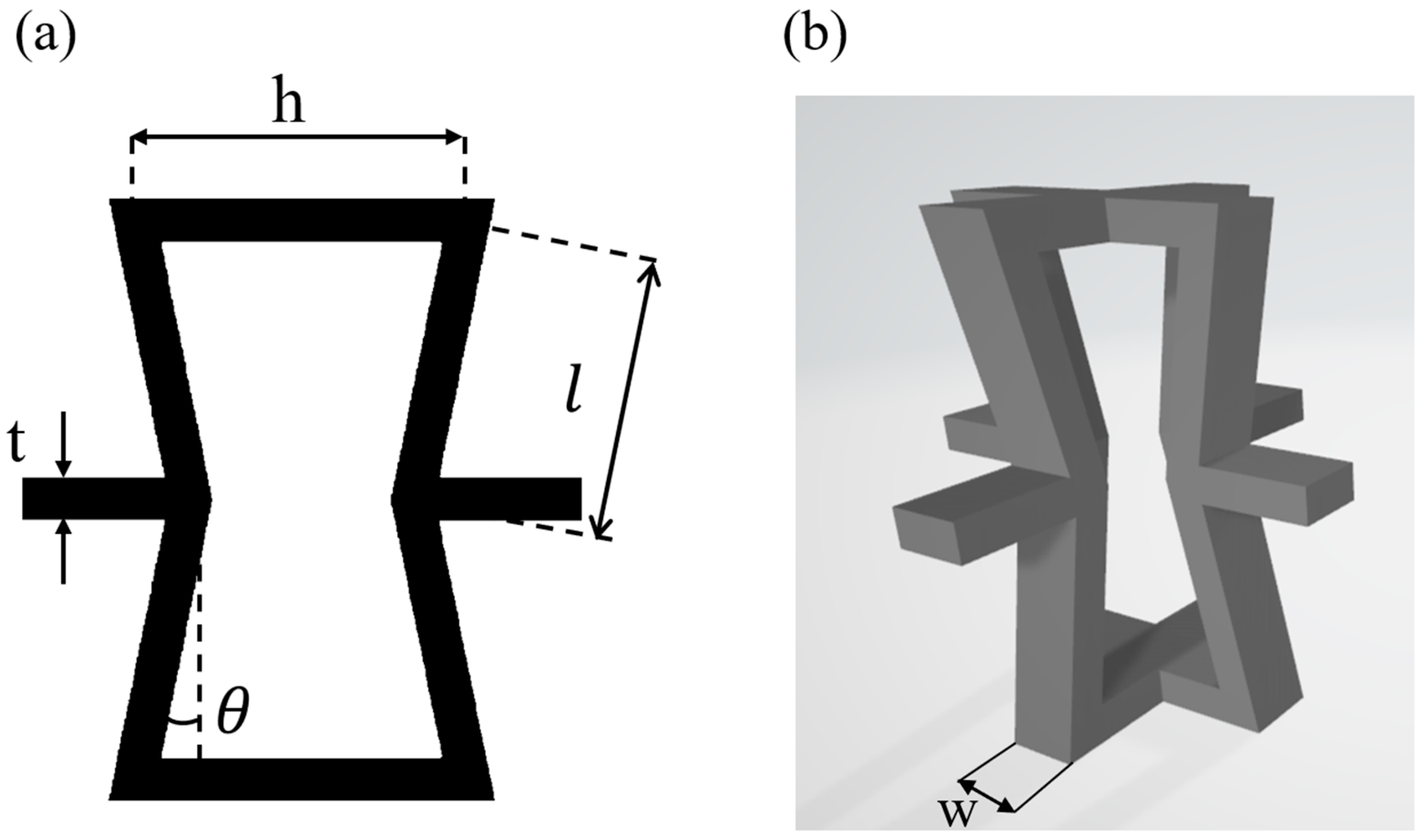
Figure 1. (a) Two-dimensional view of a re-entrant honeycomb unit cell, and (b) Three-dimensional view of a re-entrant honeycomb unit cell.
Buildings 15 02878 g001
Figure 2. Numerical model of a 3D NPR system with re-entrant honeycomb structures.
Buildings 15 02878 g002
Figure 3. The geometry settings of the 2D unit cell.
Buildings 15 02878 g003
Figure 4. Uniaxial stress–strain relations: (a) elastoplastic constitutive model, and (b) elastoplastic constitutive model combined with a damage criterion.
Buildings 15 02878 g004
Figure 5. The GIMP models with different cell sizes (0.8 mm, 0.6 mm, 0.4 mm, and 0.2 mm).
Buildings 15 02878 g005
Figure 6. Undeformed (top row) and deformed (bottom row) patterns for the four different GIMP models.
Buildings 15 02878 g006
Figure 7. Convergence study of cell size: (a) simulated Poisson’s ratio versus cell size, and (b) absolute error relative to the calculated result.
Buildings 15 02878 g007
Figure 8. Verification of angle sensitivity: (a) simulated Poisson’s ratio as a function of ligament angle, and (b) absolute error with respect to the analytical prediction.
Buildings 15 02878 g008
Figure 9. Deformed configurations with different displacements of the top plate.
Buildings 15 02878 g009
Figure 10. Relationship of Poisson’s Ratio with different top-plate displacements.
Buildings 15 02878 g010
Figure 11. Distribution of equivalent plastic strain (elastoplastic model).
Buildings 15 02878 g011
Figure 12. Distribution of damaged points (elastoplasticity combined with damage model).
Buildings 15 02878 g012
Figure 13. (a) Reaction load–deformation curves of the 3D NPR material with all three different constitutive models and theoretical elastic curve; and (b) detailed reaction load–deformation curves with the elastoplasticity and elastoplasticity combined with damage criterion. There is a delay in raising the load level due to the wave propagation to the bottom layer.
Buildings 15 02878 g013
Figure 14. The computational settings for evaluating impact resistance.
Buildings 15 02878 g014
Figure 15. Reaction–load (on the bottom layer) history curves for the NPR and solid models, with the (left) figure showing the real load level and the (right) figure describing the details at low load level, respectively. The difference in time delay between the NPR and solid models could be better observed in the (right) figure.
Buildings 15 02878 g015
Figure 16. Kinetic energy–displacement response of the auxetic (NPR) lattice versus a solid block under identical impact loading.
Buildings 15 02878 g016
Figure 17. Distributions of equivalent plastic strain (top row) and equivalent stress (bottom row) for the NPR model at different instants.
Buildings 15 02878 g017
Figure 18. Distributions of equivalent plastic strain (top row) and equivalent stress (bottom row) for the pure solid model at different instants.
Buildings 15 02878 g018
Disclaimer/Publisher’s Note: The statements, opinions and data contained in all publications are solely those of the individual author(s) and contributor(s) and not of MDPI and/or the editor(s). MDPI and/or the editor(s) disclaim responsibility for any injury to people or property resulting from any ideas, methods, instructions or products referred to in the content.