Article

Natural Fiber TRM for Integrated Upgrading/Retrofitting

1
Department of Civil Environmental Engineering and Architecture, University of Cagliari, Via Marengo 2, 09123 Cagliari, CA, Italy
2
Department of Civil Engineering, University of Salerno, Via Giovanni Paolo II n.132, 84084 Fisciano, SA, Italy
*
Author to whom correspondence should be addressed.
Buildings 2025, 15(16), 2852; https://doi.org/10.3390/buildings15162852
Submission received: 24 June 2025 / Revised: 5 August 2025 / Accepted: 8 August 2025 / Published: 12 August 2025
(This article belongs to the Collection Sustainable and Green Construction Materials)

Abstract

Sustainability in the construction and building sector with the use of greener and more eco-friendly building materials can minimize carbon footprint, which is one of the prime goals of the twenty-first century. The use of natural fibers in ancient and traditional buildings and structures is not new, but in the last fifty years, only man-made fibers have predominantly occupied the market for structural retrofitting or upgrading. This research investigated the potential of utilizing natural fibers, particularly jute fiber products, to enhance masonry’s thermal and structural characteristics. The study meticulously investigated the utilization of materials such as jute net (with a mesh size of 2.5 cm × 1.25 cm), jute fiber diatons, and jute fiber composite mortar (with 1% jute fiber with respect to the dry mortar mass) in the context of masonry upgrading. The research evaluated the structural and thermal performance of these upgraded walls. Notably, the implementation of natural fiber textile-reinforced mortar (NFTRM) resulted in an astounding increase of over 500% in the load-bearing capacity of the walls, while simultaneously enhancing insulation by more than 36%. Furthermore, the study involved a meticulous analysis of crack patterns during in-plane cyclic testing utilizing the advanced Digital Image Correlation (DIC) tool. The upgraded/retrofitted wall exhibited a maximum crack width of approximately 7.84 mm, primarily along the diagonal region.

1. Introduction

Carbon footprint is one of the menaces that is directly responsible for global warming and therefore leads to climate change. Notably, the construction and building (C&B) sector is accountable for directly and indirectly producing about 39% of total CO2 and other greenhouse gases globally, with 36% being from the European Union (EU) [1]. The C&B sector also consumes about 36% of the total energy produced globally, whereas this percentage is 40% in the EU [2].
Commercially, man-made fibers like carbon [3], basalt [4], polyethylene terephthalate [5], polyvinyl alcohol [6], and nets/fabrics fabricated with steel fibers, carbon, glass, aramid, and Polyparaphenylene benzobisoxazole are used for structural and non-structural restoration and interventions [7]. Notably, fiber-reinforced polymer (FRP) [8,9] is preferred for almost all structural retrofitting or upgrading for its higher strength and well-established existing guidelines and standards [10].
Recently, textile-reinforced mortar (TRM) retrofitting/upgrading (as in Al-Saidi Y. et al. [11], Kouris L.A.S et al. [12], Marques A.I. et al. [13], Gulinelli P. et al. [14]) has become a well-accepted masonry retrofitting/upgrading technique, and it is stalwartly competing with FRP retrofitting or upgrading techniques due to its various advantages over the FRP system [15].
One notable advantage of the TRM is a high strength-to-weight ratio, which enhances its mechanical performance [15]. Additionally, this material does not require any organic additives [15] and is ideal for countering limited deformations in masonry [15]. There is also good chemical–physical compatibility between the composite and masonry substrates [16]. This material can retain its performance even at high temperatures [17] and can improve ductility, among other benefits.
According to [18] and later confirmed in [16], there are no universally recognized standards for designing, testing, and qualifying TRM systems worldwide, except for those developed by the United States (US), such as RILEM TC 250-CSM [19] and ACI 549 [20]. However, guidelines and recommendations have been prepared by CNR DT 215 (2018) [15], which are recognized by the Italian government.
In the literature, the numerous applications of man-made fiber-based TRM for structural retrofitting and upgrading are mainly used for its enhanced strength, modulus of elasticity, and durability [21] compared to natural fiber TRM systems. However, research and development (R&D) of the use of natural fiber TRM applications, like Flex-TRM [22], jute, Sisal, hemp, and flex TRM [23], banana TRM [24], hemp TRM [25] systems, etc., are also gaining momentum, intending to replace the use of man-made fiber.
In [23], the experimental study assessed the mechanical performance of natural fiber-reinforced composites for masonry strengthening. The mortar-based composites (NFRCM) with jute fiber (in two different categories) showed moderate tensile strengths between 25.9 MPa (with a modulus of elasticity of 531 MPa) and 35.6 MPa (with a modulus of elasticity of 346 MPa). A mortar composite with flax showed tensile strength of 57.2 MPa and a modulus of 774 MPa, as well as better compatibility with masonry. Meanwhile, a mortar composite with hemp fiber had the lowest tensile strength of 3.1 MPa (with a modulus of elasticity of 268 MPa).
Enhancing the thermal and structural performance of buildings is of paramount importance to bolster their overall sustainability and resilience. The integration of thermal upgradation (such as improved insulation and energy efficiency) with structural enhancements and seismic retrofitting serves to optimize energy efficiency as well as improve the overall longevity and robustness of the building. Further, this holistic approach effectively harmonizes the structural integrity, thereby contributing to an extended building lifespan, decreased maintenance expenditures, and a reduced environmental footprint stemming from less frequent renovation activities, leading to a more sustainable built environment overall. In recent years, there has been a surge in research interest in the application of TRM systems for strengthening masonry buildings or structures through integrated (structural and thermal) retrofitting/upgrading.
Several recent studies have investigated integrated (thermo-structural) retrofitting of masonry walls using Textile-Reinforced Mortar (TRM) systems combined with thermal insulation materials, most notably Expanded Polystyrene (EPS). Triantafillou et al. (2017) [26] pioneered this approach, using a commercial fabric-TRM system with EPS and reporting an increase in peak load (out-of-plane tests), though no experimental thermal data was provided. Peak loads obtained for Series A were found to be between 9.28 kN and 20.26 kN, whereas Series B found values to be between 5.37 kN and 10.74 kN (3.42 kN for the reference sample).
In a follow-up study, Triantafillou et al. (2018) [27] used glass-TRM and EPS for integrated retrofitting, with ranging structural improvements (in-plane cyclic load). Peak-load values obtained for Series A, Series B, and Series C were noted to be from 31.5 kN to 39.3 kN (19.9 kN for the reference sample), 29.2 kN to 37.1 kN (20.0 kN for the reference sample), and 24.3 kN to 36.8 kN (12.2 kN for the reference sample), respectively.
Gkournelos et al. (2020) [28] have performed out-of-plane and in-plane tests on masonry wall samples. For integrated retrofitting, the improvement in shear strength (the case of the in-plane cyclic test) was found to be 0.85 MPa when compared with the reference sample. For the out-of-plane tests, the load-bearing capacity increased by 19.3 kN compared to the reference sample.
Karlos et al. (2020) [29] have performed analytical, numerical, and experimental studies. The experimental results indicate that the peak in-plane loads for the integrated retrofitted walls increased significantly, ranging from 10.01 kN to 20.26 kN, compared to just 3.42 kN for the reference wall.
More recently, Longo et al. (2021) [30] studied the integrated behavior by incorporating steel-TRM and glass-TRM for structural enhancement and using natural hydraulic lime and geopolymer lime for thermal retrofitting. The shear strengths of the glass fiber and steel fiber-reinforced walls were found to be between 0.818 (MPa) to 1.298 (MPa) and 1.058 (MPa) to 1.480 (MPa). Meanwhile, the thermal transmittance values of the retrofitted masonry walls decreased by 24.98% to 49.52% W/m2K compared to un-strengthened samples.
Baek et al. (2022) [31] introduced an innovative system with Basalt-TRM and a Textile Capillary Tube Panel (TCP), which improved lateral load capacity by 41.46% to 126%.
Gkournelos et al. (2023) [32] tested man-made fiber-TRM with EPS, reporting shear and peak load gains of 14.29% and 46.00%, respectively.
Finally, Furtado et al. (2023) [33] applied glass-TRM with ETICS and RTIM, noting a peak load increase between 44.44% and 122.22%, with thermal performance derived from material conductivity values.
In the majority of the aforementioned integrated retrofitting/upgrading research works, as in Triantafillou et al. (2017) [26], Triantafillou et al. (2018) [27], Gkournelos et al. (2020) [28], and Baek et al. (2022) [32], the authors inferred improvements in thermal insulation capacity due to the application of EPS in the TRM system without conducting experiments.
The Digital Image Correlation (DIC) method is a well-known method for analyzing and determining the geometry, displacement, and string of deformations in observed specimens. As stated in [34], the DIC was already in use in the 1980s. Digital Image Correlation (DIC) has gained significant attention among researchers due to its ability to provide non-contact, full-field measurements. This optical technique enables the determination of 2D or 3D coordinates, which are then used to assess key parameters such as displacement and strain [35].
This paper is a continuation of the authors’ previous experimental work, which was conducted at the fiber level to evaluate the physical and mechanical properties of raw jute fibers, jute fiber threads, and jute fiber diatons [36]. This was followed by an analysis of the thermo-mechanical properties at the material level, with a focus on jute fiber composite mortar [37].
The novelty of this paper is that it is the first time that a structural-level natural (jute) fiber TRM system (NFTRM system) has been used for integrated (structural and thermal) retrofitting/upgrading. The TRM system consists of all jute fiber products like jute fiber nets, jute fiber diatons, and jute fiber-composite mortar, and this is the only research to date that has used all the aforesaid products together.

2. Materials and Methods

The objective of this research work was to upgrade masonry walls (Figure 1) using products fabricated with jute fiber: (1) nets, (2) diatons, and (3) composite mortar. The prime goal was integrated (structural and thermal) upgrading. The jute fiber used in this experimental campaign and its corresponding products were not subjected to any treatment.

2.1. Raw Jute Fiber and Jute Fiber Threads

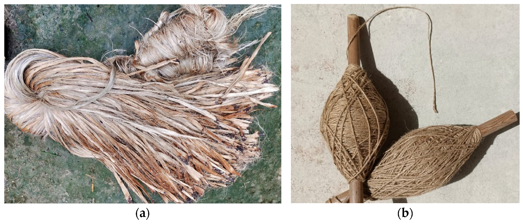
The golden shine raw jute fiber (Figure 2a) type, also known as Bangla Tosha—Corchorus olitorius, was collected from West Bengal, India. Jute thread (Figure 2b) of class 1 mm, made from the same jute fiber origin, was collected from the same place. Table 1 presents the mechanical properties of the raw jute fibers and threads; for details, see [36].

2.2. Jute Fiber Diatons

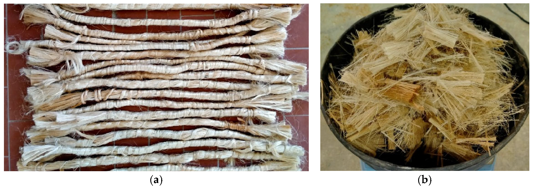
Subsequently, raw jute fibers (Figure 2a) were used for the fabrication of the jute fiber diatons (Figure 3a), and these diatons were used for structural upgrading. These diatons are important structural elements mainly used to improve the shear resistance of the applied structures. The same raw jute fibers were chopped into 30 mm (Figure 3b) jute fiber lengths, and later, these fibers were used for composite mortar preparation. Table 1 presents the mechanical properties of the jute fiber diatons; for details, see [36].
Notably, Strain energy (kN.mm) mentioned in Table 1 and Table 2 have been calculated, it represents the area under the load (kN) versus displacement (mm) curve. It indicates a material’s energy absorption capacity. An increased strain energy capacity is especially valuable for mitigating the effects of extreme loads, such as during earthquakes.

2.3. Jute Fiber Nets

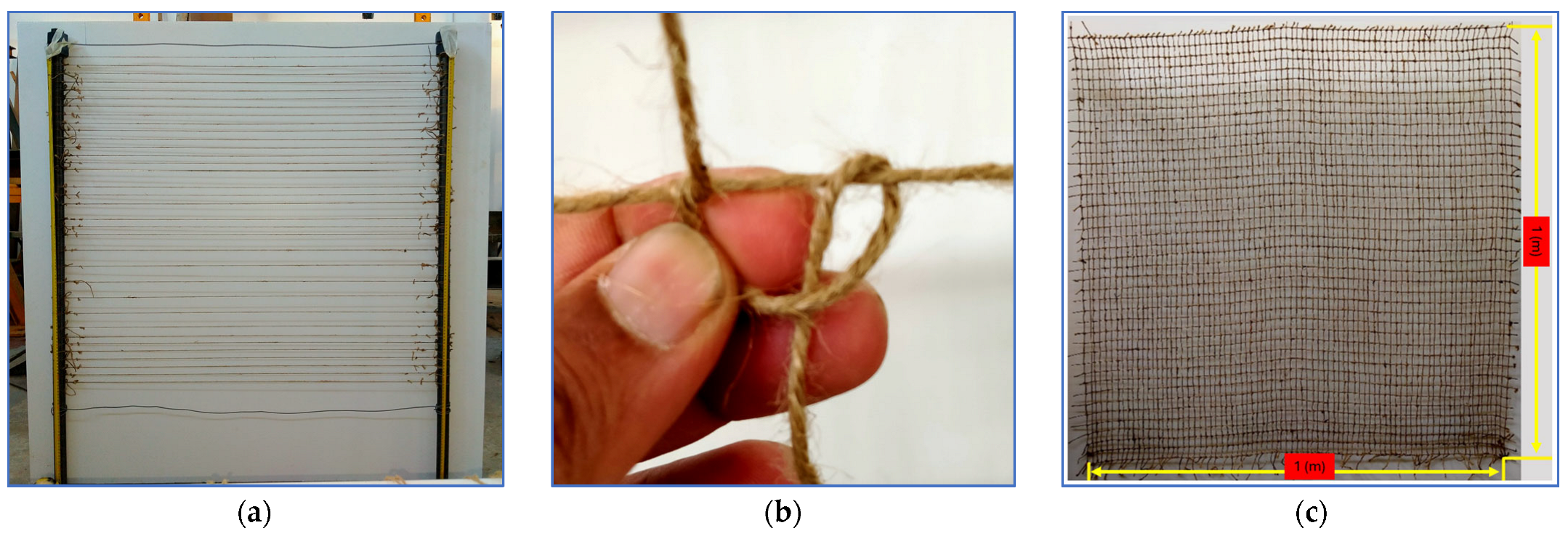
Class 1 mm jute threads were used for the fabrication of the jute fiber nets. Figure 4a represents the initial preparation phase of the jute fiber nets, whereas Figure 4b demonstrates a typical knot that was chosen for the net fabrication. All jute nets (Figure 4c) were prepared manually at the structural laboratory of the University of Cagliari, Italy. Two types of jute nets were used during this experimental campaign: (a) 1 m × 1 m nets for retrofitting/upgrading the structural test samples and (b) 0.9 m × 0.7 m nets for retrofitting/upgrading the thermal conductance test samples.
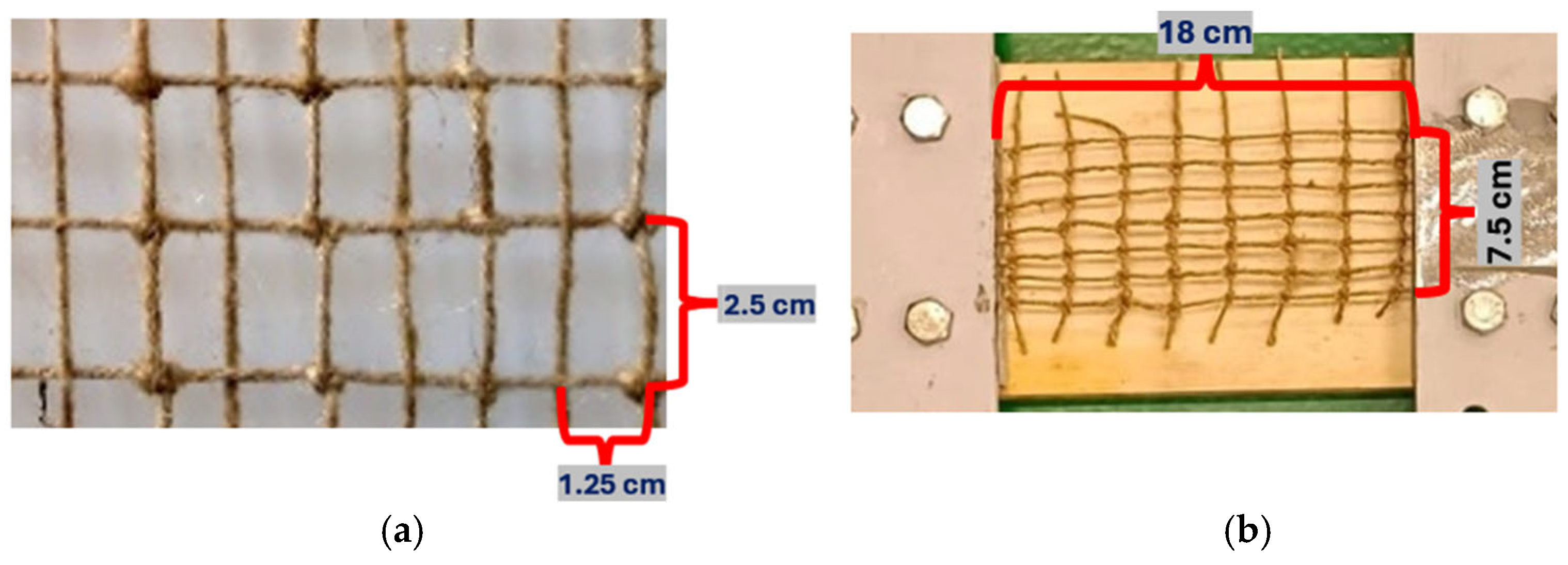
The jute net’s mesh dimension (Figure 5a) was randomly selected to keep sufficiently large gaps to allow proper mortar penetration during net installation. The objective was to create a proper bonding between the net and mortar to have an ideal composite matrix.
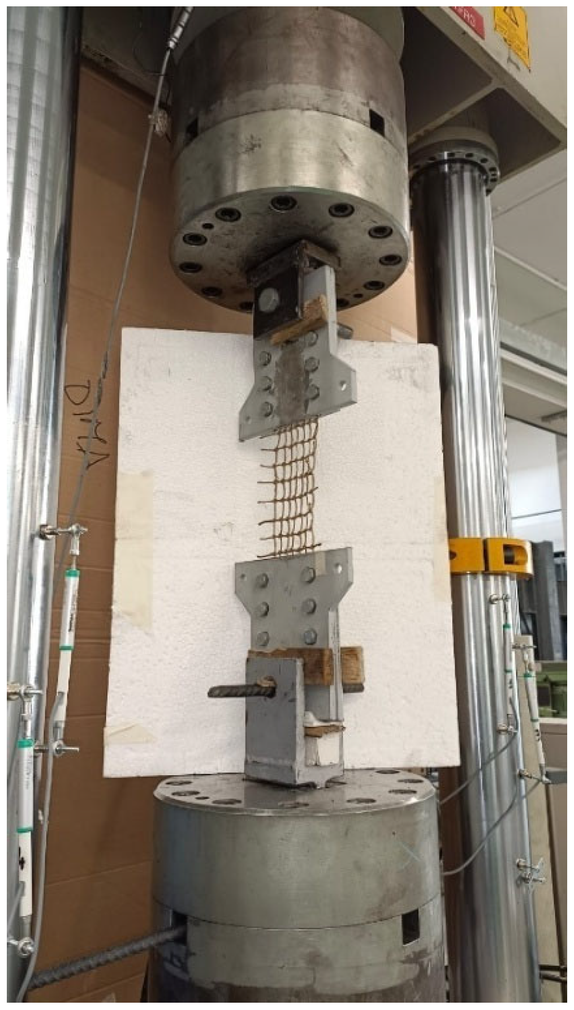
For the tensile strength test, approximately 18 cm of the net was exposed to the loads (Figure 5b), secured between two fixed-clamp fixtures tightened to 50 N/m with a torque wrench. The tensile tests were performed using a Schenck universal testing machine with a maximum load capacity of 630 kN and a maximum workable length of 20 cm. To know more about the sample preparation and test procedure, please see the authors’ previous work [10].
The tensile strength tests (Figure 6) were carried out at a loading rate of 2 mm/min. The machine is designed to measure the applied tensile force and is linked to a dedicated computer equipped with software for generating the required graphs. A total of five specimens were tested, and the mechanical properties of the jute fiber net with a configuration of 2.5 cm × 1.25 cm are reported in Table 2.

2.4. Mortar and Jute Fiber Composite Mortar

The structural mortar (SM) is a pre-mixed mortar made for masonry. It consists of hydraulic binders and selected aggregates. Table 3 represents the specification of the SM mortar provided by the manufacturer.
The composite mortar was prepared by adding 1% of jute fiber (by mass) to the standard mortar (SM). The 30 mm fiber length was selected for this purpose. Approximately 22% water, relative to the total mass of the mortar and fibers, was used during the preparation.
It is important to note that the jute fibers used were in their natural form (chopped into 30 mm lengths) and untreated. During the preparation of the composite mortar, it was observed that fibers tended to clump together upon contact with water, forming fiber balls, which further hindered the formation of a uniform fiber–mortar mixture.
The combination of 1% of jute fiber with respect to the mortar mass and the fiber length of 30 mm was selected based on two chosen criteria: (1) various tests conducted with various fiber percentages and fiber lengths (Figure 7) (for more details, see [36,37]) and (2) the fact that the presence of fiber should not be higher than 1% in an incombustible composite mixture [39].
The optimal mortar–jute fiber combination for thermo-structural retrofitting or upgrading of masonry walls was selected based on the tests, and corresponding results are presented in Table 4. The selection aimed for balanced thermo-mechanical properties in the composite mortar.

2.5. Masonry Wall

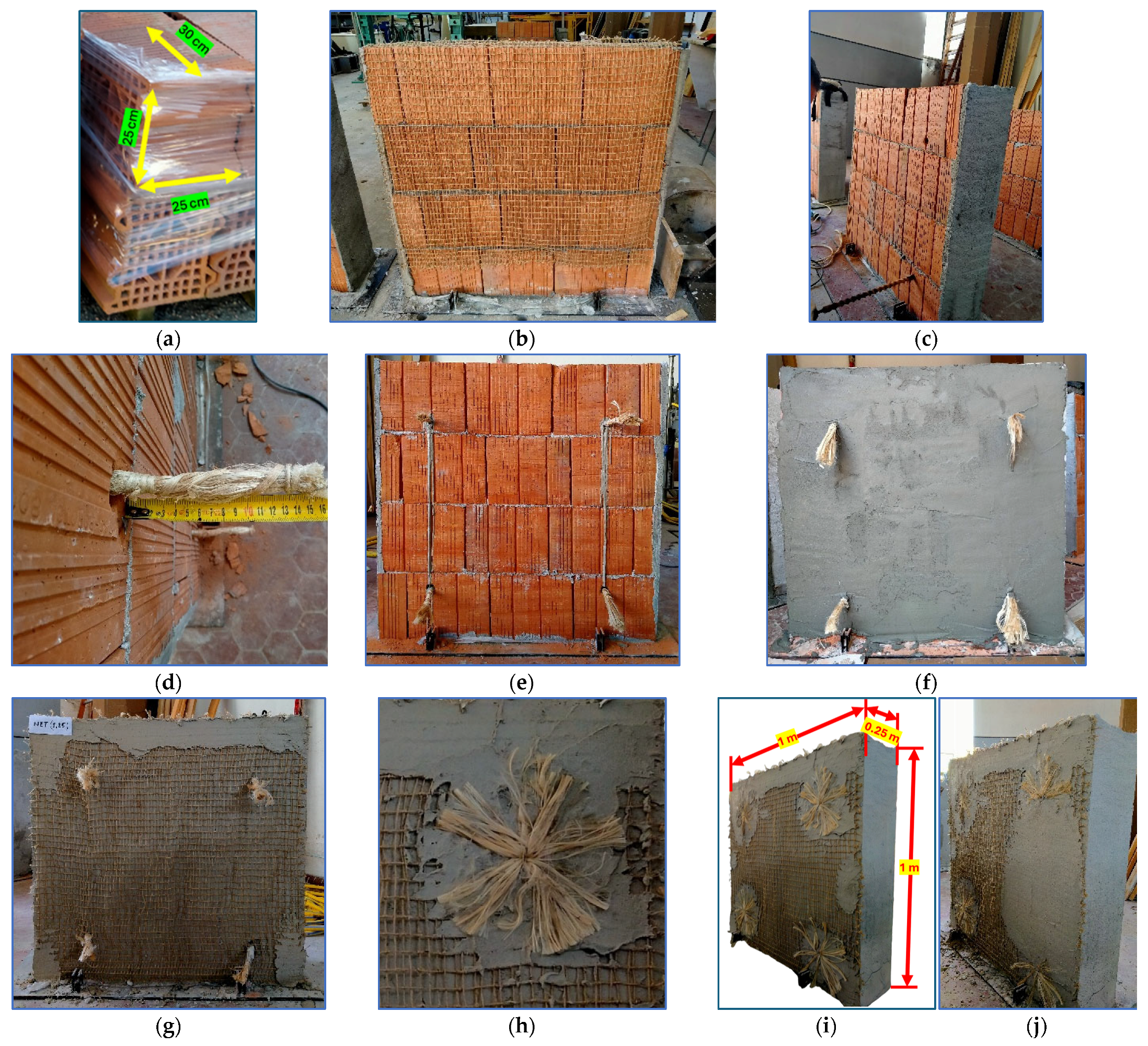
Hollow bricks of dimension 300 mm × 250 mm × 250 mm (Figure 8a) and structural mortar (SM) have been used for the construction of all un-strengthened (Figure 8b) and upgraded/retrofitted masonry walls.
Table 5 presents the various building materials and specifications used for the masonry (un-strengthened and upgraded/retrofitted) wall construction.
Notably, two different wall dimensions were considered for the structural and thermal performance evaluations (Table 5). Thermal conductance test walls had smaller dimensions due to the fact that construction windows inside the chamber had dimensions of 0.9 m × 0.7 m × 0.25 m.
A complete NFTRM package consisting of jute fiber products (jute fiber nets, jute fiber diatons, and jute fiber composite mortar) was used for the masonry walls’ upgrading/retrofitting.
The strengthening of the masonry wall started with drilling four holes for the diatons’ insertion (Figure 8c). After diatons were placed through the holes (Figure 8d), fast-drying liquid mortar was used to fill the gaps around the diatons (Figure 8e). A thin layer of mortar (SM) was applied (Figure 8f) to fix nets on both sides (Figure 8g). Diatons (Figure 8h) were open to anchor nets (Figure 8i) on both sides of the masonry wall. Finally, the composite mortar was applied (Figure 8j).

2.6. Structural Tests

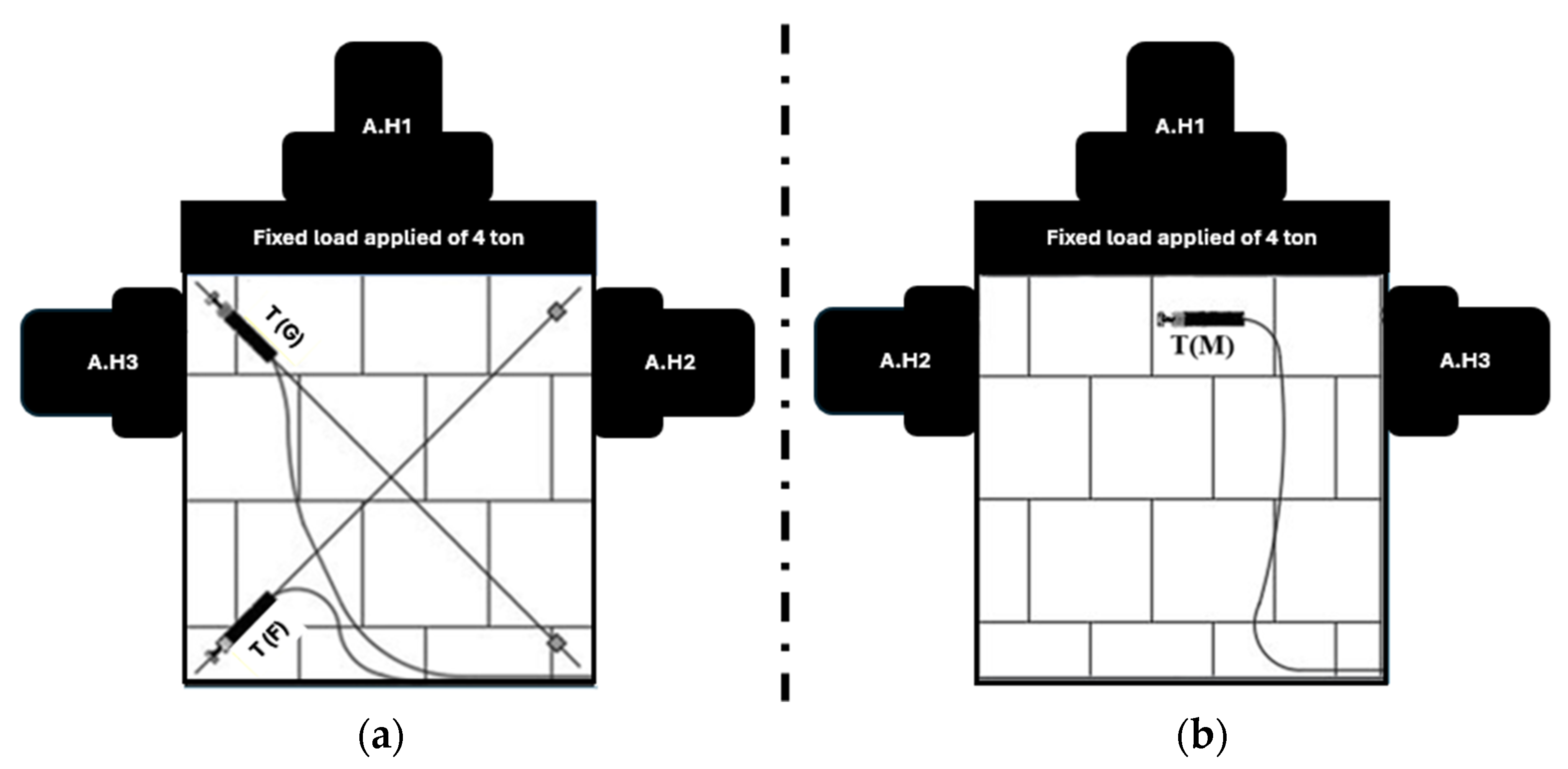
To assess the seismic performance of masonry walls, both un-strengthened and upgraded specimens were subjected to a controlled structural testing program. The quasi-static load protocol was defined as in Figure 9: the test setup involved the application of a fixed vertical load of 4 tons using the hydraulic jack labeled A.H1 to simulate the gravitational load from upper structures. Following this, in-plane cyclic lateral loads were applied to the walls using two additional hydraulic jacks, A.H2 and A.H3, placed on opposite sides of the wall. These lateral loads were intended to mimic the effects of seismic forces on the wall system, applied alternately from both directions until the wall reached complete failure.
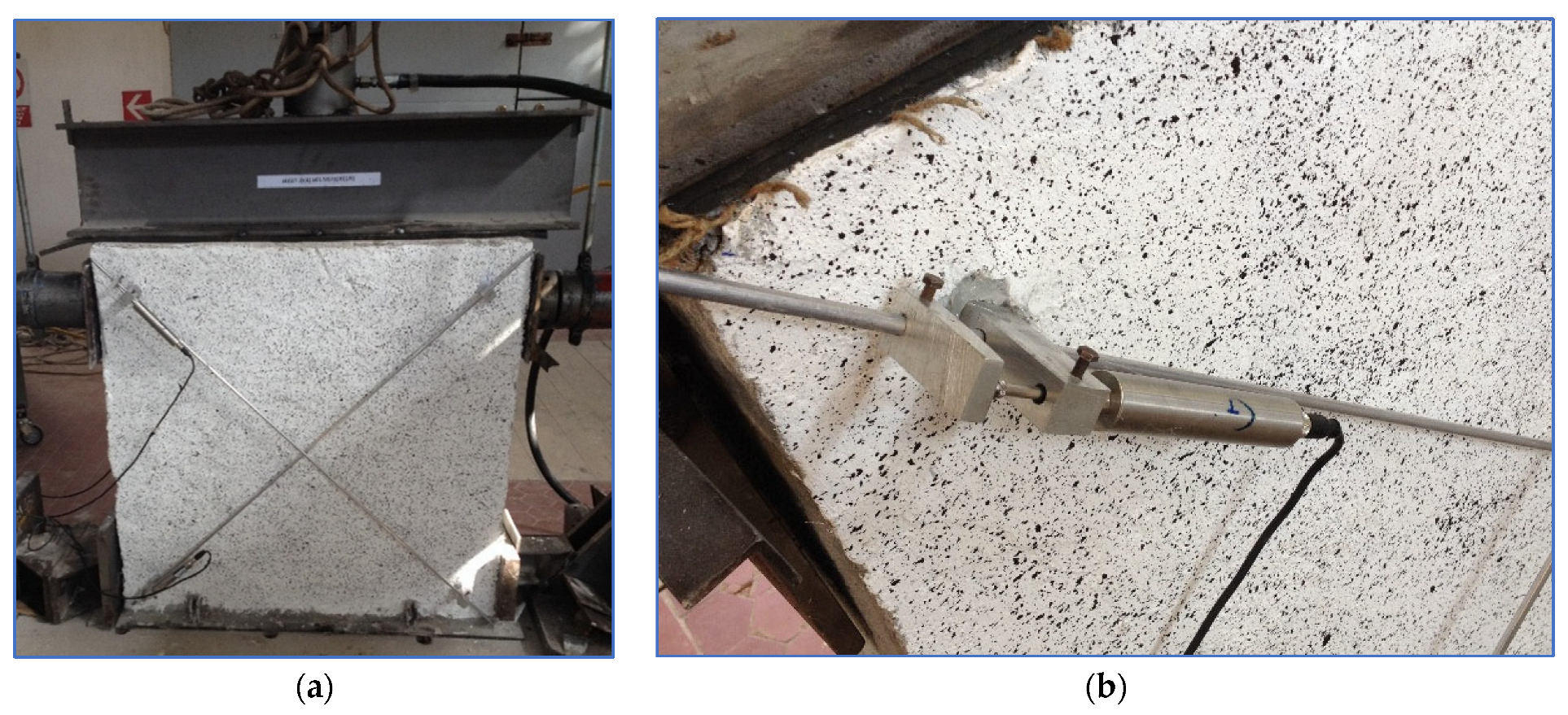
Figure 9 illustrates the overall configuration of the masonry wall test setup. It shows the three hydraulic jacks: A.H1 applying the fixed vertical load at the top and A.H2 and A.H3 applying lateral loads from the right and left sides, respectively. In addition, three displacement transducers (T(G), T(F), and T(M)) were installed on the wall. As can be seen in Figure 9a, T(G) and T(F) were placed diagonally (Figure 9a), crossing each other on the front face, and T(M) was placed horizontally at the back of the masonry wall, as seen in Figure 9b.
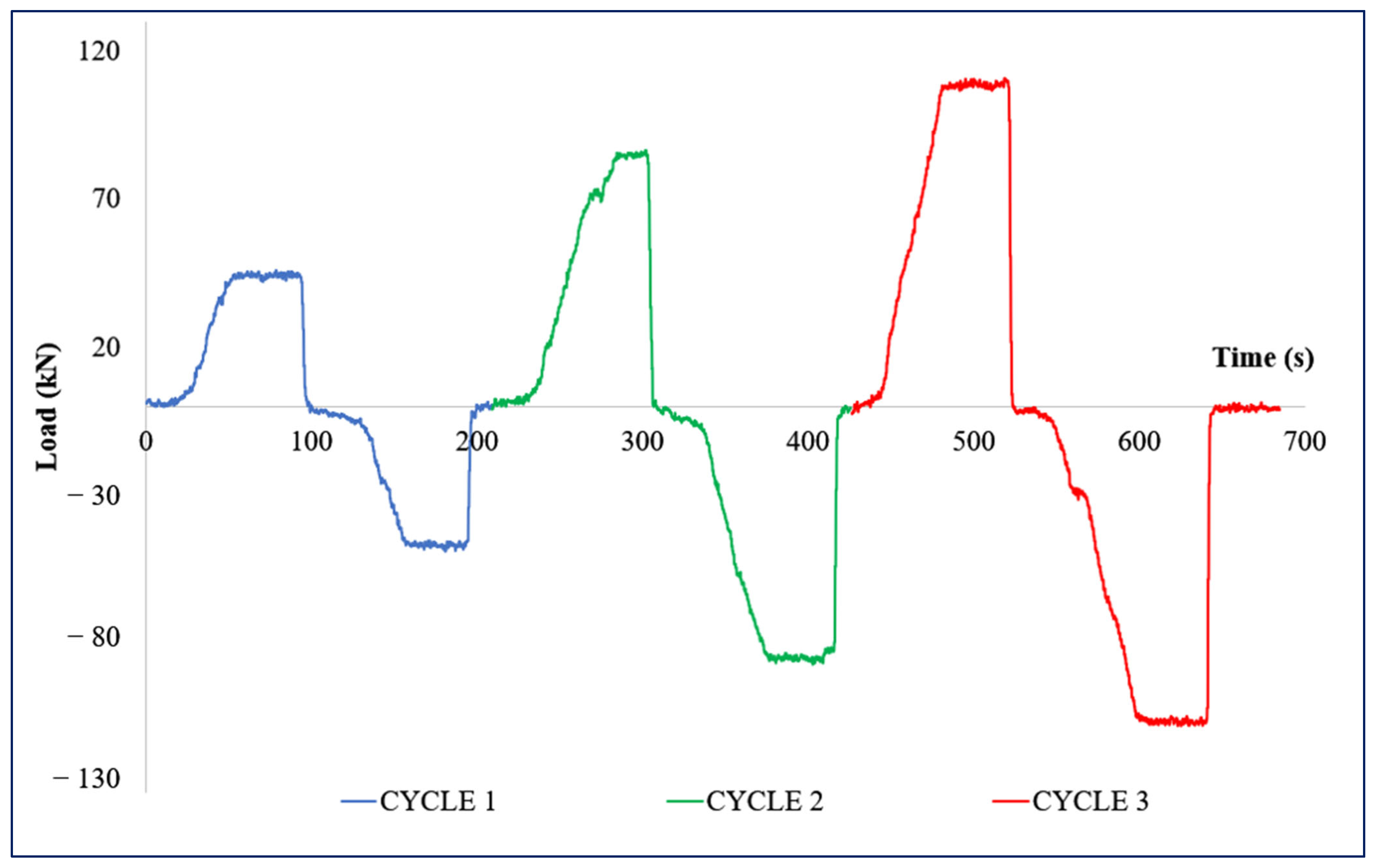
Figure 10 shows the cyclic loading sequence applied during the test using jacks A.H2 and A.H3. Each lateral jack underwent a series of controlled load applications in both directions to simulate real earthquake loading conditions. The diagram outlines three distinct loading cycles, where each cycle comprises bidirectional loading at increasing magnitudes: Load 1, Load 2, and Load 3. In the first complete cycle, Load 1 (targeted loads were 15 kN for un-strengthened masonry wall and 50 kN for upgraded/retrofitted masonry wall) was applied using A.H2 (pushing from the right), followed by a corresponding Load 1 application using A.H3 (pushing from the left). This was repeated for Load 2 and Load 3 in the second (targeted loads were 35 kN for the un-strengthened masonry wall and 90 kN for the upgraded/retrofitted masonry wall) and third (targeted load was 120 kN for the upgraded/retrofitted masonry wall) cycles, respectively. These alternating and increasing loads test the wall’s ability to absorb and dissipate energy under cyclic shear forces, which is characteristic of seismic activity. Jack A.H3 was used for the ultimate load cycle to determine the load-bearing capacity of the masonry walls (un-strengthened and TRM-upgraded).
The transducers were designed to monitor the deformation of the wall during the loading process. Their technical specifications included a nominal displacement capacity of 100 mm, a sensitivity of 2 mV/V with a tolerance of ±0.1%, and a measurement resolution of 1 μm. These parameters allowed for precise detection of even very small displacements in the wall, enabling accurate tracking of strain development and potential crack formation.
Figure 11a presents the test setup of the masonry wall specimen with the installed hydraulic jacks and transducers. The wall is mounted within a steel testing frame, with the hydraulic jacks attached to opposite sides to apply cyclic shear forces. The transducers can be seen connected to the surface of the wall (Figure 11b), capturing diagonal displacements. Figure 9b offers a close-up view of one transducer-T(G), emphasizing the installation method. The device is securely attached to the wall using clamps and mounting hardware.
This experimental setup simulates masonry wall behavior during earthquakes. The fixed vertical load represents the building’s weight, while cyclic lateral loads mimic seismic forces. Lateral applied loads are known, whereas the transducers accurately measure the diagonal and axial deformations, providing valuable data for the un-strengthened and upgraded masonry wall samples.

2.7. Thermal Tests

The Biemme TH Climate Chamber (CC) was used to characterize masonry walls’ thermal characterization (Figure 12a). The CC has three parts: two movable chambers and a fixed central wall (Figure 12b). The CC was manufactured according to the European regulation EN 1934:2000 [40]. The masonry wall samples (of dimensions 0.9 m × 0.7 m × 0.25 m, as in Figure 12c) were prepared inside the expandable polystyrene (EPS) wall, which behaves as a heat flow protective wall. Figure 12d presents a typical upgraded wall sample with heat flux and temperature sensors. For these tests, temperature sensors (class A) and heat flux meters (which had an accuracy of 5% @T = 20 °C) were used.
Two desired environmental conditions (outside cold and inside room conditions) were set (Table 6) for two movable chambers with hot and cold sides, respectively.

2.8. DIC Analysis

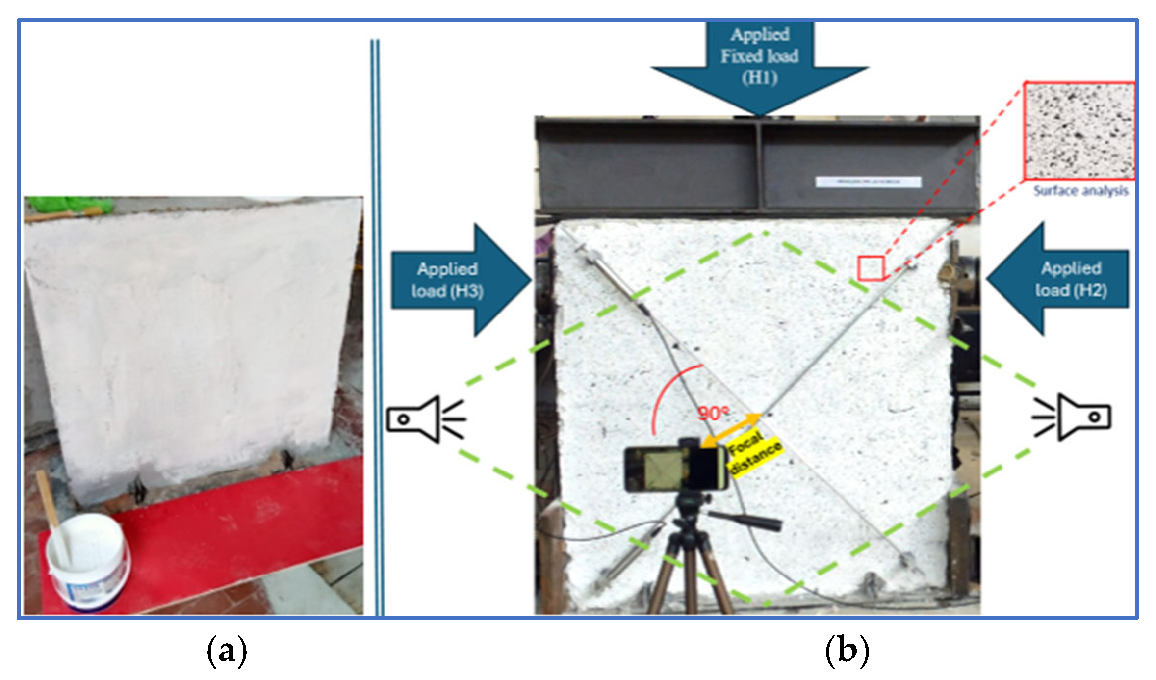
The specimens were prepared for DIC analysis following the guidelines in [34,41]. Digital Image Correlation (DIC) was used to analyze surface deformation during testing. The specimen surface was first painted white (Figure 13a), followed by a random spray of black speckles (Figure 13b) to create a high-contrast pattern. This speckle pattern in DIC provides a high-contrast texture that allows software like GOM Correlate (2019 version) to track surface deformation. The black speckles on a white background create unique features for the software to monitor changes between images. A calibrated camera, positioned directly in front of the specimen and supported by two artificial light sources, captured high-resolution images (1920 × 1080 pixels) at 0.5 s intervals, synchronized with the load-displacement system. A total of 115 images were analyzed, with the 6th image showing the widest crack and subsequent images reflecting stabilized crack propagation. DIC results enabled precise measurement of crack openings, later compared across different fiber contents and lengths.

3. Results and Discussion

This section highlights the results of the integrated (structural and thermal) retrofitting based on a comparison between the NFTRM-upgraded masonry wall sample and the non-retrofitted naked masonry wall sample.

3.1. Structural Properties

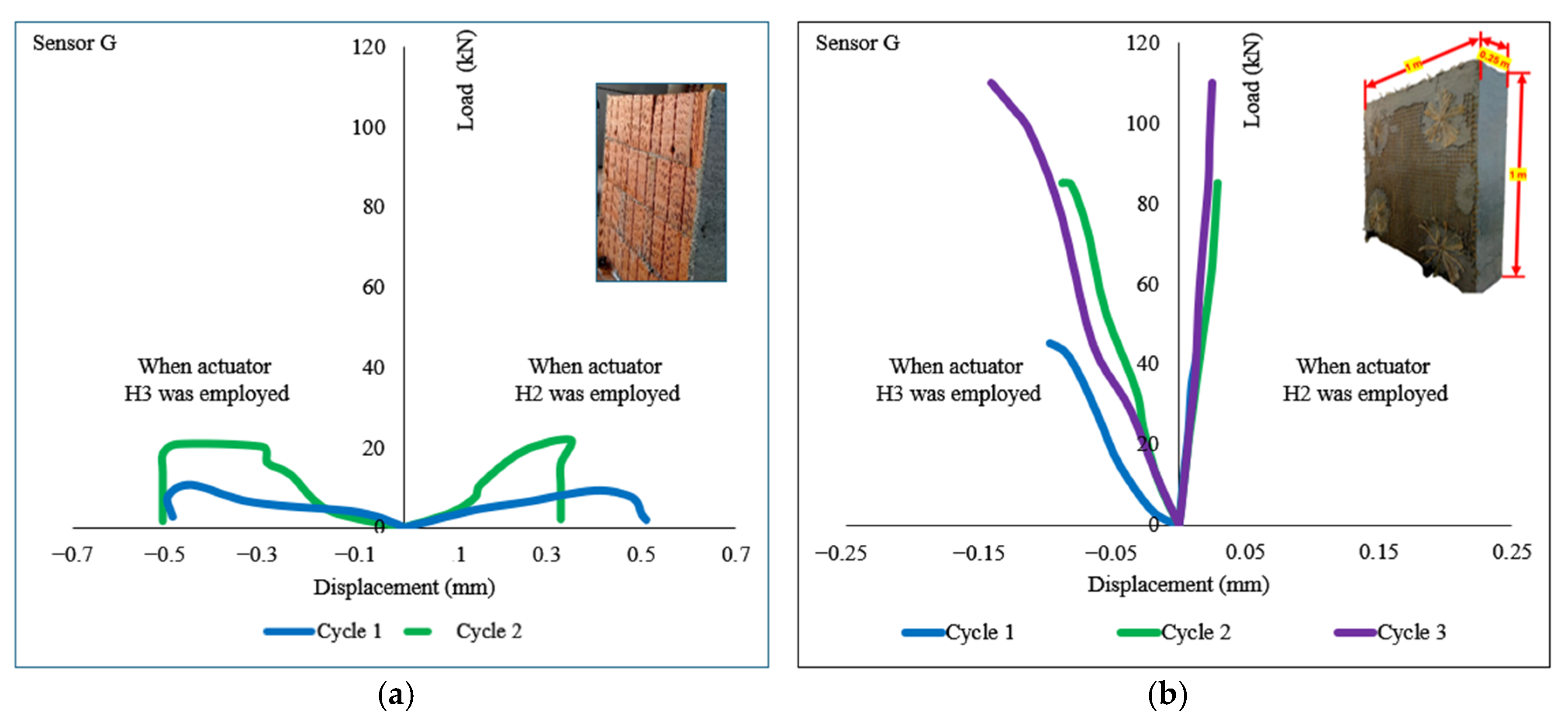
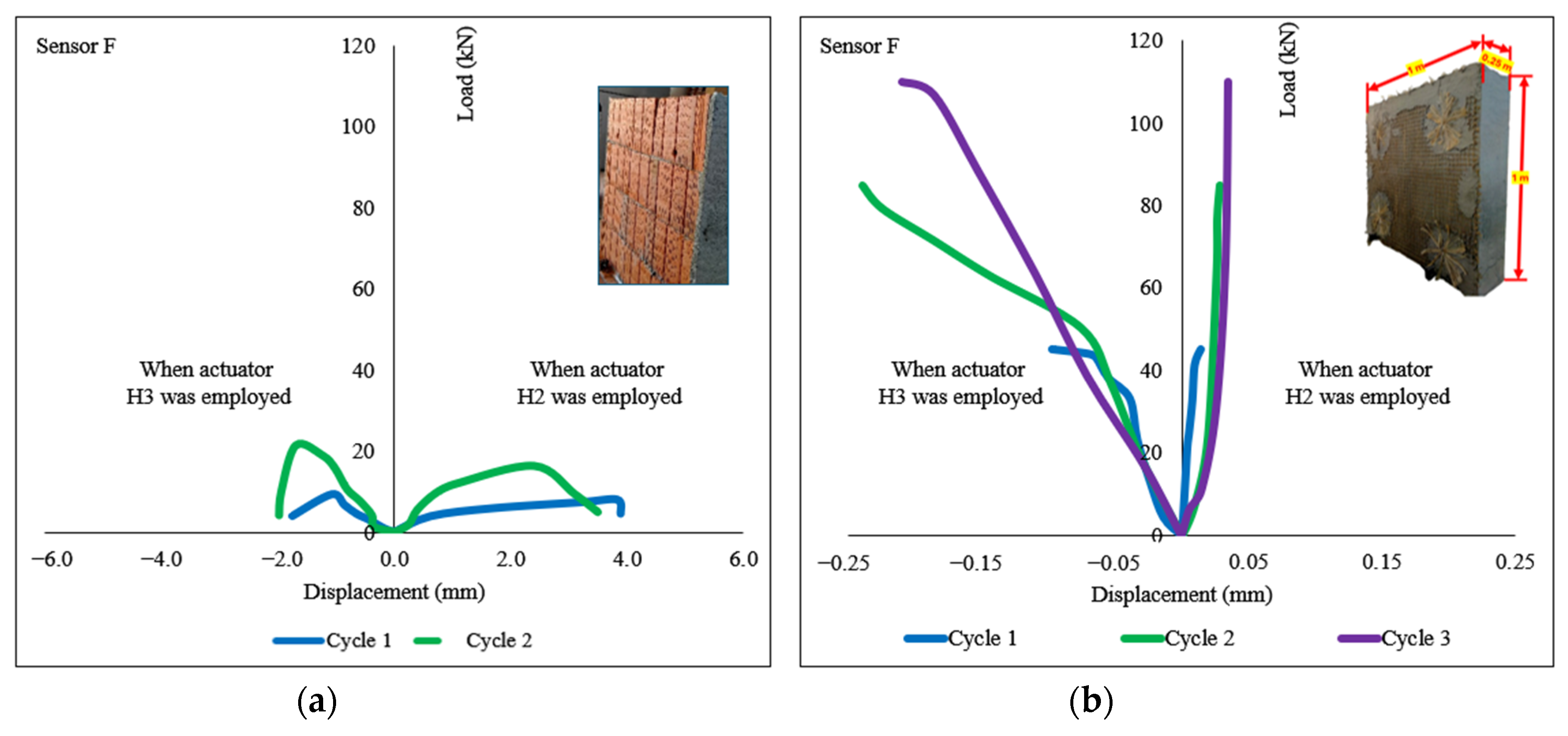
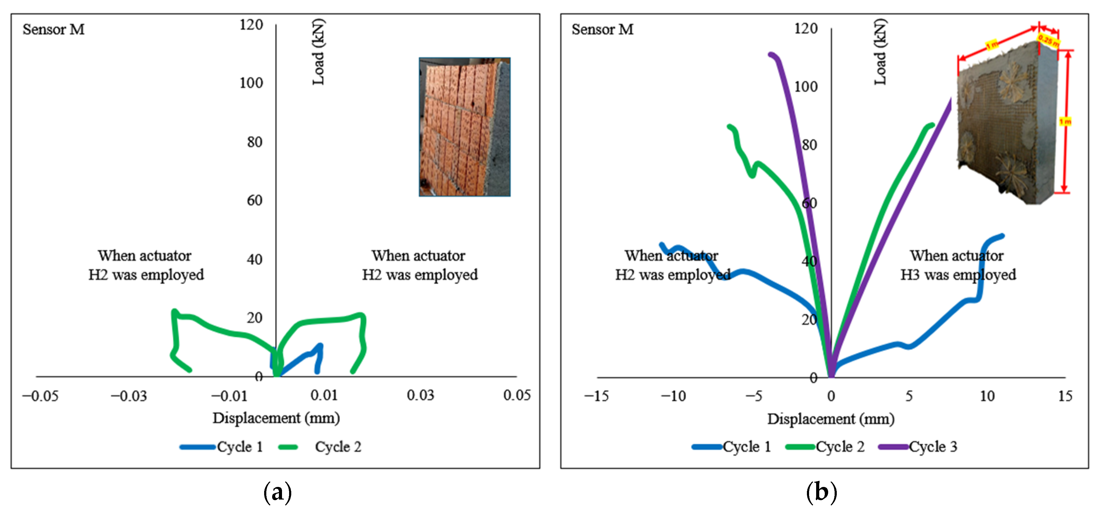
Figure 14, Figure 15 and Figure 16 present applied load-displacement graphs for two load cycles (for the un-strengthened masonry wall) and three load cycles (for the upgraded/retrofitted masonry wall) involving actuators H3 and H2. The target loads of 45 kN, 85 kN, and 110 kN were selected for Cycle 1, Cycle 2, and Cycle 3, respectively. The displacements were measured using sensors, namely diagonal sensors (T(G) and T(F)) and horizontal sensors (T(M)). For actuator H3, the diagonal sensor T(G) records negative displacement values, while T(F) shows positive values, indicating differing deformation responses. In contrast, actuator H2 exhibits a similar trend in diagonal sensors but with higher absolute values for T(F), suggesting greater displacement. The horizontal sensor T(M) records positive displacement for H3 and negative for H2. The results highlight differing sensor responses based on orientation; therefore, displacements may be either positive or negative depending on the direction of the applied forces. The structural response of the wall has not been entirely symmetrical in all instances, which may be attributed to potential issues in sensor placement, explaining the variations between the positive and negative displacement regions.
The load was applied using actuators, while diagonal displacement responses were recorded by Sensor G (Figure 14a for un-strengthened masonry wall and Figure 14b for retrofitted masonry wall) and Sensor F (Figure 15a for un-strengthened masonry wall and Figure 15b for retrofitted masonry wall) under different actuator load conditions.
Un-strengthened and upgraded/retrofitted graphs illustrate two or three loading cycles, respectively (Cycle 1 in solid blue, Cycle 2 in dashed green, and Cycle 3 in dotted pink) under the influence of actuators H3 (left negative displacement) and H2 (right positive displacement).
For the upgraded/retrofitted masonry wall, when actuator H3 is employed, the displacement is negative, reaching around −0.05 mm for Sensor G (Figure 14b), whereas it reaches around −0.15 mm for Sensor F (Figure 15b), with load values subsequently increasing from 45 kN and 110 kN, respectively. Conversely, when actuator H2 is employed, positive displacement values remain near 0.05 mm for both sensors G (Figure 14b) and F (Figure 15b), with peak load values applied on cycle 3 of 110 kN.
Figure 16 presents comparative graphs between un-strengthened masonry walls and upgraded masonry wall samples. The load–horizontal displacement response was recorded by the horizontal transducer M under the influence of actuators H2 (negative displacement) and H3 (positive displacement). It illustrates multiple loading cycles (two load cycles for un-strengthened masonry wall and three load cycles for upgraded/retrofitted masonry wall), including Cycle 1 (solid blue), Cycle 2 (dashed green), Cycle 3 (dotted pink), and the ultimate cycle (dashed dark blue). Maximum displacements of about +11 mm and −11 mm were observed during the first cycle, when 45 kN load was applied using H3 and H2 actuators, respectively. In the second cycle, displacements of about +7 and −7 mm were observed when the 85 kN load was applied using H3 and H2 actuators, respectively. During the third cycle, when the 110 kN load was applied using H3 and H2 actuators, displacements of 4 mm and 9 mm were noted.
The un-strengthened masonry wall exhibits a significantly lower load-bearing capacity. In contrast, the NFTRM-upgraded masonry wall demonstrates a remarkable improvement in both load resistance and deformation capacity. During the ultimate load cycle, the peak load value crosses beyond 230 kN. Therefore, the upgraded NFTRM masonry wall is more than 200 kN stronger than the un-strengthened masonry wall. The result (Table 7) shows that the NFTRM strengthening technique significantly enhances the masonry wall’s strength, ductility, and energy absorption capacity.

3.2. Contribution of a Single NFTRM Layer and Theoretical Ultimate Strength

The contribution of a single NFTRM layer in the upgraded masonry wall was calculated by analyzing the theoretical ultimate strength of the wall. This involved evaluating both the intrinsic shear capacity of the un-strengthened masonry wall (Vt) and the additional contribution provided by the natural fiber textile-reinforced mortar (NFTRM) system (Vt,f). According to established formulation CNR-DT 215/2018 [15], the total shear capacity of the strengthened wall (Vt,R) is determined as the sum of these two components.
V t , R =   V t +   V t , f   kN
The Vt was calculated using [15] and experimental results, and validated against the Italian Building Code [42], incorporating parameters such as wall dimensions, applied top load (Ftop), and average normal stress (σ0).
V t = H · t · 1.5   τ 0 d   p 1 + σ 0 1.5   τ 0 d kN
Meanwhile, σ 0   was calculated (see Table 8) using the following Equation (3):
σ 0 =   F top H · t N mm 2
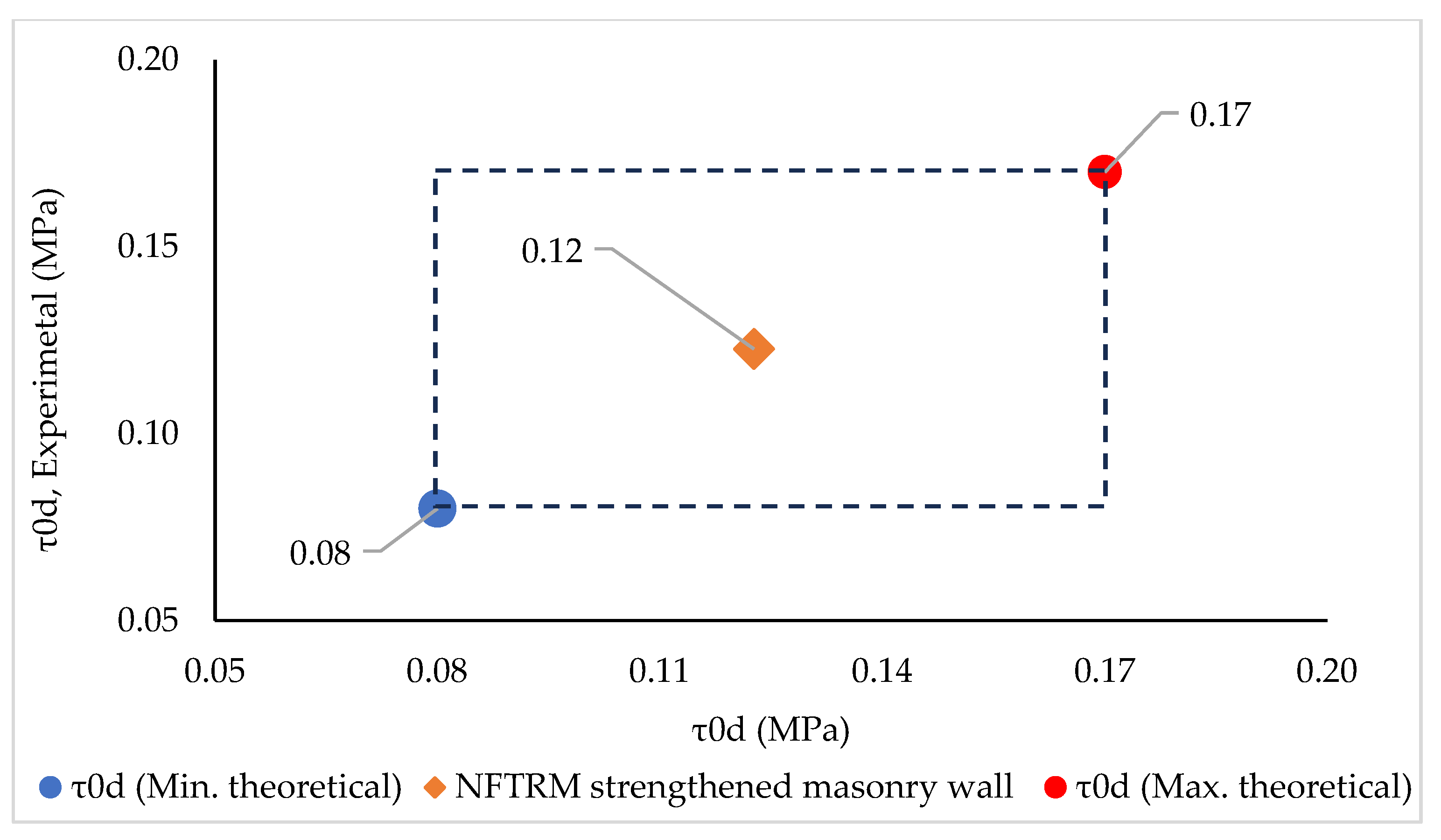
The calculated τ0d value (Table 8 and Figure 17) of the unreinforced masonry wall falls between 0.10 and 0.13 (MPa). Interestingly, this aligns with the value specified by the Italian NTC18 [42] for masonry constructed with semi-hollow clay bricks featuring dry vertical joints and a hole percentage of less than 45%. Notably for the above-mentioned calculation, only the final ultimate load cycle was considered.
The contribution of the NFTRM system Vt,f was calculated following [15,42], and using Equation (4):
V t , f = 1 γ Rd · n f · t vf · l f · α t · ε fd · E f kN
where γ Rd is the partial safety factor (Table 9).
  • n f is the total number of the reinforced layers arranged at each side of the wall (see Table 9).
  • t vf is the equivalent thickness of a single layer of the NFTRM system (see Table 9).
  • l f is the design dimension of the reinforcement measured orthogonally to the shear force; it cannot be longer than the length of the masonry wall (see Table 9).
  • α t is the coefficient to account for the reduced tensile strength of fibers when under shear stress (see Table 9).
  • E f is the Young’s/elastic modulus of elasticity of dry fabric/textile,
  • ε fd is the design strain of NFTRM.
Table 9. All known, considered, and calculated data of the upgraded masonry wall.
Partial safety factorγRd1
Total number of reinforced layers arranged at each side of the wallnf1
The equivalent thickness of a single layer of the NFTRM system tvf4.25cm
The design dimension of the reinforcement measured orthogonally to the shear force; it cannot be longer than the length of the masonry wall (lf ≤ H)lf100cm
The coefficient to account for the reduced tensile strength of fibers when under shear stressαt0.8
The NFTRM system’s design strength is
σ fd =   ε fd ·   E f   MPa
Replacing σ fd in the Equation (4), the same equation can be re-written as
V t , f = 1 γ Rd · n f · t vf · l f · α t · σ fd kN
It has been considered that the shear capacity of the strengthened wall V t , R is equal to the measured experimental value of the maximum horizontal force (Table 10).
V t , R = V t , R . exp .   kN
Using Equations (2) and (4), the contribution of the NFTRM system can be calculated as
V t , f = V t , R   V t kN
Here, it is important to note that the masonry wall was strengthened with a total of two NFTRM systems, one on each side of the wall.
Therefore, the TOTAL contribution of the two NFTRM systems (see Table 11) is calculated using the known values V t . exp . (see Table 9) and V t , R . exp . (see Table 10).
V t , f . TOTAL = V t , R . exp .   V t . exp .   kN
Here, it has been considered that both NFTRM systems performed alike; therefore, the contribution of a single NFTRM system (see Table 11) was found to be
V t , f = V t , f . TOTAL 2   kN
Considering the NFTRM system’s ultimate strain equal to ε u , f , the ultimate strain can be written as
σ u , f = ε u , f · E f   MPa
Therefore, to evaluate the NFTRM system’s ultimate limit state capacity, Equation (11) has been enforced to modify Equation (6) and updated as below:
V t , f = 1 γ Rd · n f · t vf · l f · α t · σ u , f   kN
So, it should be noted that this modification was made, considering that the ultimate strength ( σ u , f ) and the design strength ( σ fd ) have the same value.
Meanwhile, the NFTRM system’s ultimate strength (Table 12) is calculated using Equation (13):
σ u , f = V t , f 1 γ Rd · n f · t vf · l f · α t = V t , R V t 1 γ Rd · n f · t vf · l f · α t   kN

3.3. Thermal Properties

Figure 18 illustrates the dissection scheme of the NFTRM-upgraded/retrofitted masonry wall, showing all its layers.
The thermal conductance tests were performed in the following three phases: (i) on an unreinforced masonry wall, (ii) on the upgraded/retrofitted (wall jute nets + diatons + SM) masonry wall, and (iii) on the masonry wall enhanced with a jute fiber composite thermal layer wall.
Using Equation (14), the heat transfers from selected indoor (room) to outdoor ambient conditions can be calculated as
Q ˙ = U · A · Δ T   W
where U is the thermal transmittance (W/m2K), Tin. = indoor temperature, Tamb. = outdoor temperature, A is the surface area (m2), and Δ T = Tamb. Tin. (K).
U can be written as
U = 1 R Total   ( W / m 2 K )
where R Total is the total thermal resistance in m2K/W.
R Total = R in . + R 1.1 + R wall + R 2.2 + R 2.1 + R amb .   ( m 2 K / W )
where
  • Rin. = Indoor (room) resistance,
  • R1.1 = Composite mortar resistance (towards indoor),
  • R2.1 = Net, diatons and mortar resistance (towards indoor),
  • Rwall = Masonry wall resistance,
  • R2.2 = Net, diatons and mortar resistance (towards outdoor),
  • R1.2 = Composite mortar resistance (towards outdoor),
  • Ramb. = Ambient/outdoor resistance.
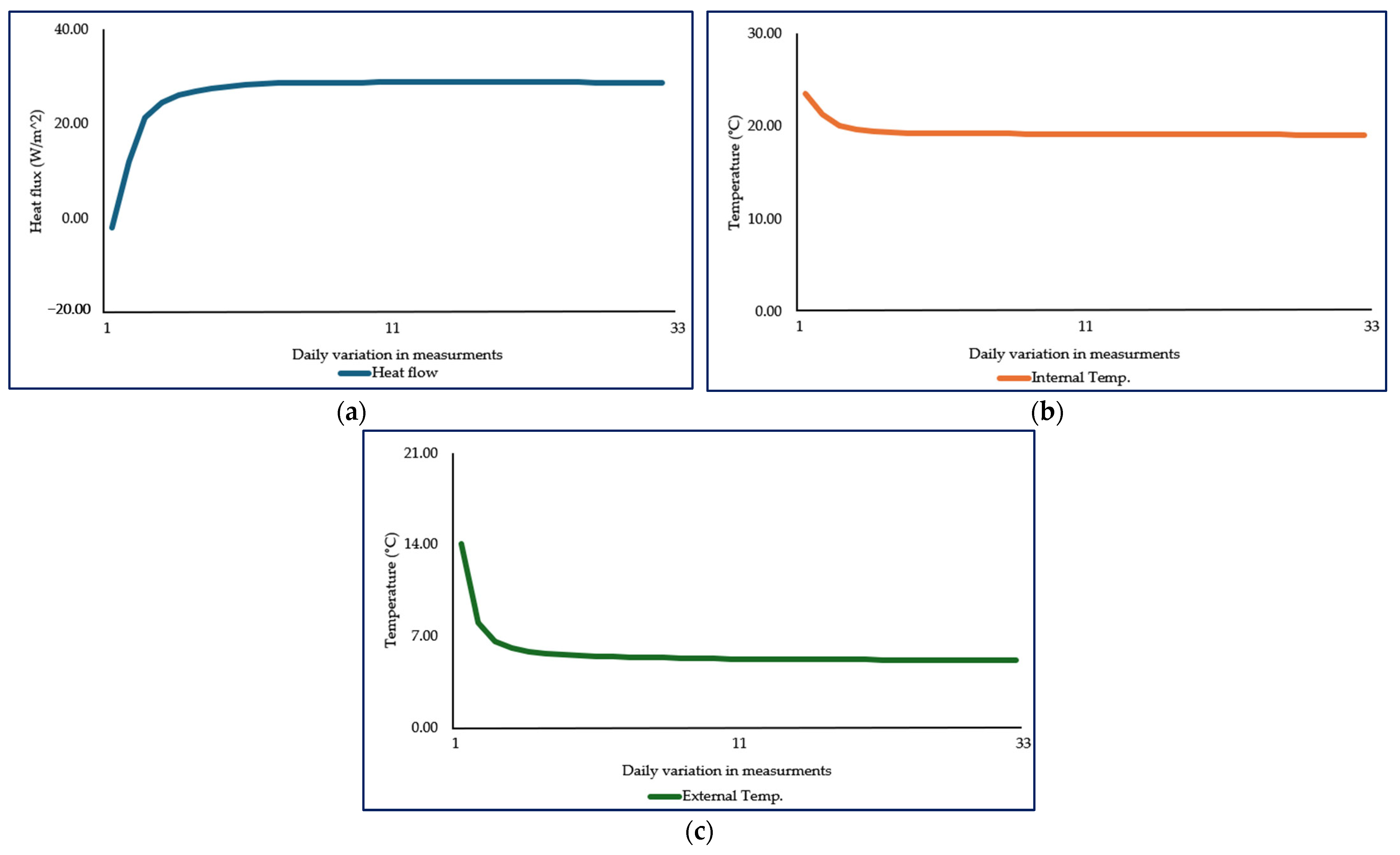
To achieve the steady-state conditions test, heat fluxes (W/m2) as well as internal and external temperatures (°C) were continuously monitored (see Figure 19). Quasi-steady conditions were reached after approximately twenty days. Particularly, the heat flux was considered acceptable and steady when the cumulative moving average of the heat flux remained within ±1% for a continuous period of at least 24 h.
Therefore, based on the measurements in the climate chamber, the thermal resistance of each aforementioned layer was calculated (see Table 13).
Thereafter, the thermal transmittance of the NFTRM-upgraded/retrofitted masonry wall was calculated using Equation (15); see Table 14.

3.4. Integrated Behavior

It has been observed that due to the application of the NFTRM system, the load-bearing capacity as well as the insulation capacity of the same wall increased (representing reduction in the thermal transmittance value). The findings in Table 15 demonstrate that the natural fiber textile-reinforced mortar (NFTRM) system provides a highly effective and balanced solution for both structural and thermal retrofitting of masonry walls, outperforming many conventional man-made fiber-based TRM systems. Structurally, the NFTRM-upgraded wall exhibited an exceptional 574.29% increase in load-bearing capacity, far exceeding the improvements reported in other studies, which ranged from 14.29% to 1481.25% depending on the fiber type (glass, basalt, steel) and testing conditions (in-plane, out-of-plane, or shear tests). While some man-made fiber systems achieved high strength gains (for example., Gkournelos et al. (2020) [28] reported 1481.25% in in-plane tests), these were often under specific loading scenarios, whereas NFTRM delivered consistent and substantial reinforcement.
Thermally, the NFTRM system achieved a 36.99% reduction in thermal transmittance, a significant improvement that was experimentally verified. In contrast, most man-made fiber TRM studies relied on Expanded Polystyrene (EPS) for thermal insulation without direct experimental validation, attributing improvements solely to the insulating material rather than the composite system. Only Longo et al. (2021) [30] and Baek et al. (2022) [32] provided experimental thermal data, with reductions of 24.98–49.52% and variable results for Basalt-TRM with TCP insulation. The NFTRM system’s thermal performance is particularly notable because it does not depend on synthetic insulation like EPS, making it a more sustainable solution.
The natural fiber textile-reinforced mortar (NFTRM) system developed in the current study demonstrates a remarkable improvement in both structural and thermal performance, surpassing previous reinforcement methods that relied on glass, basalt, steel, and synthetic fiber-based TRM systems. Beyond structural benefits, NFTRM also offers a significant reduction in thermal transmittance value, making it a competitive alternative to traditional TRM systems in all cases where authors have used EPS for insulation enhancement. While previous studies integrated EPS to improve thermal efficiency, the current project achieved comparable thermal benefits without relying on synthetic insulation materials; rather, it used jute fiber products (jute fiber net, jute fiber diatons, and jute fiber composite mortar) to achieve it, thereby promoting sustainability. By utilizing natural fibers instead of synthetic alternatives, the NFTRM system not only enhances masonry wall durability but also supports eco-friendly construction practices. These findings establish NFTRM as a sustainable alternative to conventional TRM techniques which mainly use man-made fibers (like glass, basalt, carbon, steel, etc.), offering unparalleled structural reinforcement, significant thermal efficiency, and environmental benefits over previous fiber-based reinforcement strategies. Overall, the NFTRM system has proved to be an ideal solution for its dual functionality, offering exceptional structural reinforcement alongside substantial thermal improvement without relying on additional insulation layers. This makes it a more sustainable, efficient, and cost-effective alternative to traditional TRM retrofitting methods, which often require separate structural and thermal upgrades. The results suggest that natural fiber-based systems could be a superior choice for integrated masonry wall retrofitting, balancing performance, sustainability, and practicality.

3.5. DIC Observations

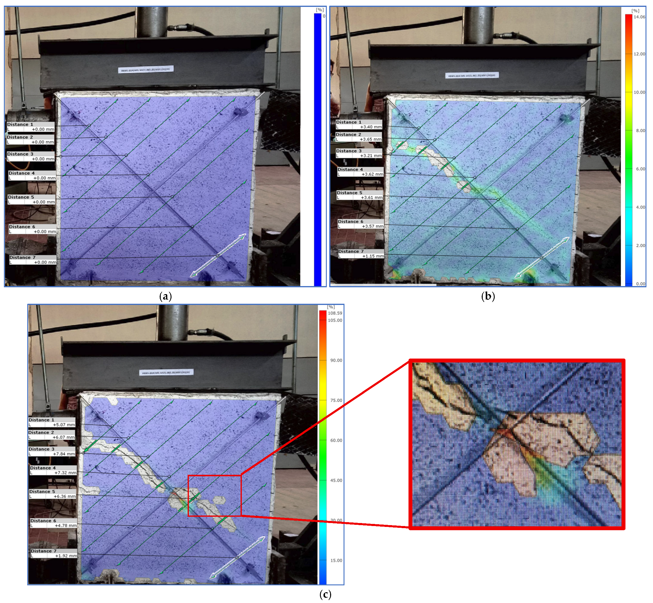
Figure 20 illustrates the outcome of the DIC interpretation of the deformation behavior of an upgraded masonry wall (NFTRM-upgraded masonry wall sample) before and during the in-plane cyclic test. In Figure 20a, the wall is shown in its initial, undeformed state, with the surface uniformly prepared and a virtual measurement grid applied. All measured displacement values across the monitored paths (Distances 1 to 7) are recorded as 0.00 mm, confirming that the wall has not yet been subjected to any loading. This baseline condition is critical for establishing a reference point from which all subsequent displacements can be measured.
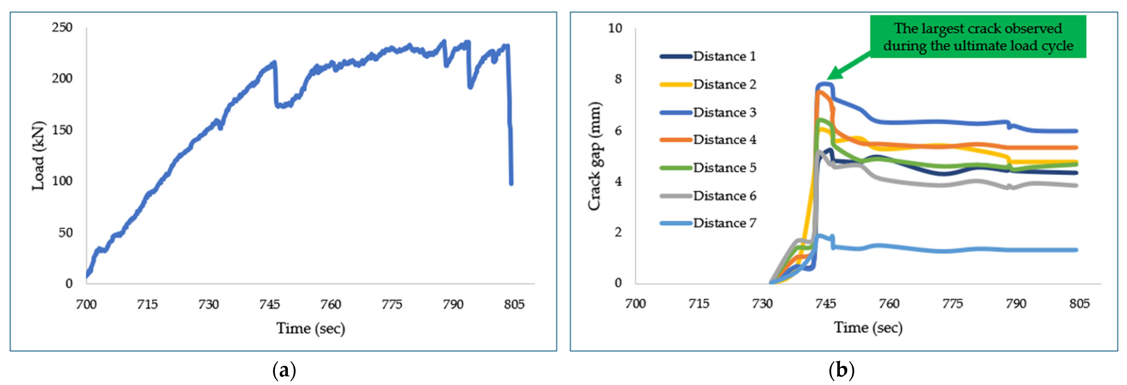
Figure 20b,c present the DIC results captured during the ultimate load cycle of the masonry wall, offering a more detailed analysis of the failure behavior under maximum loading. In Figure 20b, the first cracks are visible, while Figure 20c shows the observed maximum cracking gap values at each point, with the highest value at about +7.84 mm; notably, the cracking is most pronounced along the diagonal region. This stage represents the peak of structural loading, and the DIC system highlights the development of extensive shear cracks and substantial deformation. The color mapping applied to the image further emphasizes areas of high displacement, with gradients indicating how stress is distributed across the wall.
A closer view of the central region of the wall, shown in Figure 20c, highlights the localized stress pattern along the main crack, where intense color gradients—mainly red and yellow-orange—indicate zones of high strain. This confirms stress localization as the driving force behind crack propagation. Notably, even after the wall collapsed under the ultimate load, the central cross-section still shows evidence of tensile load transfer. This behavior reflects the enhanced ductility of the NFTRM-upgraded sections, achieved through the integration of natural jute fiber components, including two jute fiber nets, four jute fiber diatons, and a jute fiber-reinforced mortar containing 1% (30 mm) fibers.
These DIC analyses collectively demonstrate the powerful capability of the method to track and quantify deformation, identify crack propagation paths, and evaluate the effectiveness of structural upgrades in masonry walls.
Figure 21 presents two graphs: first, the application of load during the ultimate load cycle (Figure 21a), and second, the visible crack opening and fluctuations of the crack during this period (Figure 21b). The largest crack opening, i.e., about 7.84 mm, was observed during the ultimate load cycle.

4. Conclusions

Integrated retrofitting/upgrading could be the right choice for both structural and thermal strengthening of the existing and new masonry buildings and structures. But it should be kept in mind that structural upgrading and improvement in insulation properties are complementary to each other; therefore, the right balance between these two should be determined through deep research and development work.
During this research, for the first time, a natural fiber (jute) TRM system was used to upgrade masonry walls. The NFTRM system consists of jute fiber nets, jute fiber diatons, and jute fiber composite mortars prepared with 1% jute fiber (30 mm) with respect to the dry mortar mass.
It has been observed that with the application of the NFTRM system for upgrading, the load-bearing capacity of the upgraded masonry wall increased by more than 500%, and the thermal transmittance value reduced by more than 36%, which demonstrates improvement in the insulation capacity of the upgraded masonry wall.
Additionally, Digital Image Correlation (DIC) analysis provided detailed insight into the wall sample’s structural response before, during, and after the loading cycles. The DIC results also indirectly justify the ductile behavior of the upgraded masonry wall; further, it exhibited an enhancement in overall resistance and strain distribution capacity. Prior to loading, no deformation was observed, while post-test images revealed controlled crack propagation primarily along diagonal shear planes. During the ultimate load cycle, DIC data showed concentrated strain fields near the center of the wall, with displacement values reaching up to +7.81 mm. Therefore, these findings confirm the effectiveness of the NFTRM system in increasing not only the load-bearing capacity but also the presence of natural fiber products (jute nets, diatons, and composite mortar layer) that help improve the ductility and energy dissipation characteristics of the wall. Thus, the integration of natural fiber-based strengthening systems, validated through advanced monitoring techniques like DIC, represents a promising and sustainable approach to masonry retrofitting.

Author Contributions

Conceptualization, A.M., E.M. and F.S.; methodology, A.M., E.M. and F.S.; validation, A.M., M.V., A.F., E.M. and F.S.; formal analysis, A.M., M.V. and F.S.; investigation, A.M., M.V. and A.F.; writing—original draft preparation, A.M. and F.S.; writing—review and editing, A.M., M.V., A.F., E.M. and F.S.; supervision, A.F., E.M. and F.S. All authors have read and agreed to the published version of the manuscript.

Funding

The authors gratefully acknowledge the financial support provided by the PRIN PNRR 2022 project Integra TRM: Integrated Seismic and Thermal Upgrading of Existing Masonry Buildings through a Novel Sustainable Textile-Reinforced Mortar System (F53D23009850001), as well as by the RELUIS–DPC 2024–2026 Project, Work Package 5.

Data Availability Statement

The original contributions presented in this study are included in the article. Further inquiries can be directed to the corresponding authors.

Conflicts of Interest

The authors declare no conflict of interest.

References

  1. Benzar, B.-E.; Park, M.; Lee, H.-S.; Yoon, I.; Cho, J. Determining Retrofit Technologies for Building Energy Performance. J. Asian Archit. Build. Eng. 2020, 19, 367–383. [Google Scholar] [CrossRef]
  2. Kelly, S. REPORT on the Implementation of the Energy Performance of Buildings Directive; Committee on Industry, Research and Energy: Strasbourg, France; European Parliament: Strasbourg, France, 2021. [Google Scholar]
  3. Qin, X.; Huang, X.; Kaewunruen, S. Sustainable Design and Carbon-Credited Application Framework of Recycled Steel Fibre Reinforced Concrete. Dev. Built Environ. 2024, 18, 100404. [Google Scholar] [CrossRef]
  4. Ja’e, I.A.; Raja Sazrin, R.A.N.B.; Syamsir, A.; Bheel, N.; Amaechi, C.V.; Min, T.H.; Anggraini, V. Optimisation of Mechanical Properties and Impact Resistance of Basalt Fibre Reinforced Concrete Containing Silica Fume: Experimental and Response Surface Assessment. Dev. Built Environ. 2024, 17, 100368. [Google Scholar] [CrossRef]
  5. Kangavar, M.E.; Lokuge, W.; Manalo, A.; Karunasena, W.; Ozbakkaloglu, T. Development of Sustainable Concrete Using Recycled Polyethylene Terephthalate (PET) Granules as Fine Aggregate. Dev. Built Environ. 2023, 15, 100192. [Google Scholar] [CrossRef]
  6. Mercuri, M.; Vailati, M.; Gregori, A. Lime-Based Mortar Reinforced with Randomly Oriented Polyvinyl-Alcohol (PVA) Fibers for Strengthening Historical Masonry Structures. Dev. Built Environ. 2023, 14, 100152. [Google Scholar] [CrossRef]
  7. Majumder, A.; Stochino, F.; Fraternali, F.; Martinelli, E. Seismic and Thermal Retrofitting of Masonry Buildings with Fiber Reinforced Composite Systems: A State of the Art Review. Int. J. Struct. Glass Adv. Mater. Res. 2021, 5, 41–67. [Google Scholar] [CrossRef]
  8. Joseph, L.; Sarath Kumar, P.; Chakravarthi, E.K.; Mogal, A.; Jayanarayanan, K.; Madhavan, M.K. Experimental and Statistical Investigation on Synergistic Effect of Nano Based Epoxy Hybrid FRP on Strength and Durability of Circular Concrete Columns. Dev. Built Environ. 2023, 14, 100163. [Google Scholar] [CrossRef]
  9. He, Y.; Cai, G.; Si Larbi, A.; Malla, P.B.; Xie, C. Effect of Additional Bonded Steel Plates on the Behavior of FRP-Retrofitted Resilient RC Columns Subjected to Seismic Loading. Buildings 2025, 15, 2189. [Google Scholar] [CrossRef]
  10. Majumder, A.; Stochino, F.; Frattolillo, A.; Valdes, M.; Gatto, G.; Martinelli, E. Sustainable Retrofitting Solutions: Evaluating the Performance of Jute Fiber Nets and Composite Mortar in Natural Fiber Textile Reinforced Mortars. Sustainability 2024, 16, 1175. [Google Scholar] [CrossRef]
  11. Al-Saidi, Y.; Al-Saidy, A.H.; El-Gamal, S.; Sohel, K.M.A. Shear Strengthening of Stone Masonry Walls Using Textile-Reinforced Sarooj Mortar. Buildings 2024, 14, 2070. [Google Scholar] [CrossRef]
  12. Kouris, L.A.S.; Triantafyllou, S.P.; Bournas, D.A.; Kariou, F.A. Empirical Equations for Modelling Yarn–Mortar Debonding in TRM-Strengthened Masonry Walls Subjected to Out-of-Plane Loading. Buildings 2023, 14, 32. [Google Scholar] [CrossRef]
  13. Marques, A.I.; Ferreira, J.G.; Candeias, P.; Veiga, M.D.R. Experimental Evaluation of Brick Masonry Walls Strengthened with TRM (Textile Reinforced Mortar) Renders. Buildings 2022, 12, 840. [Google Scholar] [CrossRef]
  14. Gulinelli, P.; Aprile, A.; Rizzoni, R.; Grunevald, Y.-H.; Lebon, F. Multiscale Numerical Analysis of TRM-Reinforced Masonry Under Diagonal Compression Tests. Buildings 2020, 10, 196. [Google Scholar] [CrossRef]
  15. CNR-DT 215/2018; Guide for the Design and Construction of Externally Bonded Fibre Reinforced Inorganic Matrix Systems for Strengthening Existing Structures. National Research Council: Rome, Italy, 2019.
  16. Ferrara, G.; Caggegi, C.; Martinelli, E.; Gabor, A. Shear Capacity of Masonry Walls Externally Strengthened Using Flax-TRM Composite Systems: Experimental Tests and Comparative Assessment. Constr. Build. Mater. 2020, 261, 120490. [Google Scholar] [CrossRef]
  17. Raoof, S.M.; Bournas, D.A. TRM versus FRP in Flexural Strengthening of RC Beams: Behaviour at High Temperatures. Constr. Build. Mater. 2017, 154, 424–437. [Google Scholar] [CrossRef]
  18. De Santis, S.; Carozzi, F.G.; De Felice, G.; Poggi, C. Test Methods for Textile Reinforced Mortar Systems. Compos. Part B Eng. 2017, 127, 121–132. [Google Scholar] [CrossRef]
  19. RILEM Technical Committee 232-TDT (Wolfgang Brameshuber). Recommendation of RILEM TC 232-TDT: Test Methods and Design of Textile Reinforced Concrete: Uniaxial Tensile Test: Test Method to Determine the Load Bearing Behavior of Tensile Specimens Made of Textile Reinforced Concrete. Mater. Struct. 2016, 49, 4923–4927. [Google Scholar] [CrossRef]
  20. American Concrete Institute Committee, Guide to Design and Construction of Externally Bonded Fabric-Reinforced Cementitious Matrix (FRCM) Systems for Repair and Strengthening Concrete and Masonry Structures; American Concrete Institute, Ed.; American Concrete Institute (ACI): Farmington Hills, MI, USA, 2013; ISBN 978-0-87031-852-8. [Google Scholar]
  21. Boem, I. Masonry Elements Strengthened with TRM: A Review of Experimental, Design and Numerical Methods. Buildings 2022, 12, 1307. [Google Scholar] [CrossRef]
  22. Monaco, A.; Baldassari, M.; D’Anna, J.; Cornetti, P. Effectiveness of Flax-TRM composites under traction. Procedia Struct. Integr. 2023, 44, 2278–2285. [Google Scholar] [CrossRef]
  23. Codispoti, R.; Oliveira, D.V.; Olivito, R.S.; Lourenço, P.B.; Fangueiro, R. Mechanical Performance of Natural Fiber-Reinforced Composites for the Strengthening of Masonry. Compos. Part B Eng. 2015, 77, 74–83. [Google Scholar] [CrossRef]
  24. Pilien, V.P.; Promentilla, M.A.B.; Leaño, J.L.; Oreta, A.W.C.; Ongpeng, J.M.C. Confinement of Concrete Using Banana Geotextile-Reinforced Geopolymer Mortar. Sustainability 2023, 15, 6037. [Google Scholar] [CrossRef]
  25. Menna, C.; Asprone, D.; Durante, M.; Zinno, A.; Balsamo, A.; Prota, A. Structural Behaviour of Masonry Panels Strengthened with an Innovative Hemp Fibre Composite Grid. Constr. Build. Mater. 2015, 100, 111–121. [Google Scholar] [CrossRef]
  26. Triantafillou, T.C.; Karlos, K.; Kefalou, K.; Argyropoulou, E. An Innovative Structural and Energy Retrofitting System for URM Walls Using Textile Reinforced Mortars Combined with Thermal Insulation: Mechanical and Fire Behavior. Constr. Build. Mater. 2017, 133, 1–13. [Google Scholar] [CrossRef]
  27. Triantafillou, T.C.; Karlos, K.; Kapsalis, P.; Georgiou, L. Innovative Structural and Energy Retrofitting System for Masonry Walls Using Textile Reinforced Mortars Combined with Thermal Insulation: In-Plane Mechanical Behavior. J. Compos. Constr. 2018, 22, 04018029. [Google Scholar] [CrossRef]
  28. Gkournelos, P.D.; Triantafillou, T.C.; Bournas, D.A. Integrated Structural and Energy Retrofitting of Masonry Walls: Effect of In-Plane Damage on the Out-of-Plane Response. J. Compos. Constr. 2020, 24, 04020049. [Google Scholar] [CrossRef]
  29. Karlos, K.; Tsantilis, A.; Triantafillou, T. Integrated Seismic and Energy Retrofitting System for Masonry Walls Using Textile-Reinforced Mortars Combined with Thermal Insulation: Experimental, Analytical, and Numerical Study. J. Compos. Sci. 2020, 4, 189. [Google Scholar] [CrossRef]
  30. Longo, F.; Cascardi, A.; Lassandro, P.; Aiello, M.A. Energy and Seismic Drawbacks of Masonry: A Unified Retrofitting Solution. J. Build. Rehabil. 2021, 6, 31. [Google Scholar] [CrossRef]
  31. Baek, E.; Pohoryles, D.A.; Kallioras, S.; Bournas, D.A.; Choi, H.; Kim, T. Innovative Seismic and Energy Retrofitting of Wall Envelopes Using Prefabricated Textile-Reinforced Concrete Panels with an Embedded Capillary Tube System. Eng. Struct. 2022, 265, 114453. [Google Scholar] [CrossRef]
  32. Gkournelos, P.D.; Triantafillou, T.C. Out-of-Plane Behavior of In-Plane Damaged Masonry Infills Retrofitted with TRM and Thermal Insulation. J. Compos. Constr. 2023, 27, 04023054. [Google Scholar] [CrossRef]
  33. Furtado, A.; Rodrigues, H.; Arêde, A.; Varum, H. A Experimental Characterization of Seismic Plus Thermal Energy Retrofitting Techniques for Masonry Infill Walls. J. Build. Eng. 2023, 75, 106854. [Google Scholar] [CrossRef]
  34. Janeliukstis, R.; Chen, X. Review of Digital Image Correlation Application to Large-Scale Composite Structure Testing. Compos. Struct. 2021, 271, 114143. [Google Scholar] [CrossRef]
  35. Deák, P.; Kowalik, M. Composite Aircraft Joint Experimental Testing with Digital Image Correlation. In Proceedings of the 13th Research and Education in Aircraft Design: Conference Proceedings; Vysoké Učení Technické v Brně, Fakulta Strojního Inženýrství: Dostupné, Czech Republic, 2019; pp. 150–160. [Google Scholar]
  36. Majumder, A.; Stochino, F.; Farina, I.; Valdes, M.; Fraternali, F.; Martinelli, E. Physical and Mechanical Characteristics of Raw Jute Fibers, Threads and Diatons. Constr. Build. Mater. 2022, 326, 126903. [Google Scholar] [CrossRef]
  37. Majumder, A.; Stochino, F.; Frattolillo, A.; Valdes, M.; Mancusi, G.; Martinelli, E. Jute Fiber-Reinforced Mortars: Mechanical Response and Thermal Performance. J. Build. Eng. 2023, 66, 105888. [Google Scholar] [CrossRef]
  38. UNI EN 998-2:2010; Specification for Mortar for Masonry—Part 2: Masonry Mortar. European Committee for Standardization: Brussels, Belgium, 2010.
  39. DIN EN 13501-1; Fire Classification of Products and Building Elements—Part 1: Classification Using Data from Reaction to Fire Tests. DIN Deutsches Institut für Normung e. V. (German Institute for Standardization): Berlin, Germany, 2019.
  40. UNI EN 1934:2000; Thermal Performance of Buildings—Determination of Thermal Resistance by Hot Box Method Using Heat Flow Meter—Masonry. Ente Nazionale Italiano di Unificazione (Italian National Standardization Body): Milan, Italy, 2000.
  41. Górszczyk, J.; Malicki, K.; Zych, T. Application of Digital Image Correlation (DIC) Method for Road Material Testing. Materials 2019, 12, 2349. [Google Scholar] [CrossRef] [PubMed]
  42. NTC18; Application Circular of NTC18. Circolare n. 7 Del 21 Gennaio 2019, Istruzioni per l’applicazione Dell’«Aggiornamento Delle “Norme Tecniche per Le Costruzioni”» in Italian. Ministero Delle Infrastrutture e dei Trasporti, Consiglio Superiore dei Lavori Pubblici (C.S.LL.PP.): Rome, Italy, 2019.
  43. EN ISO 6946; Building Components and Building Elements—Thermal Resistance and Thermal Transmittance—Calculation Methods. Ente Nazionale Italiano di Unificazione (UNI): Milan, Italy, 2018.
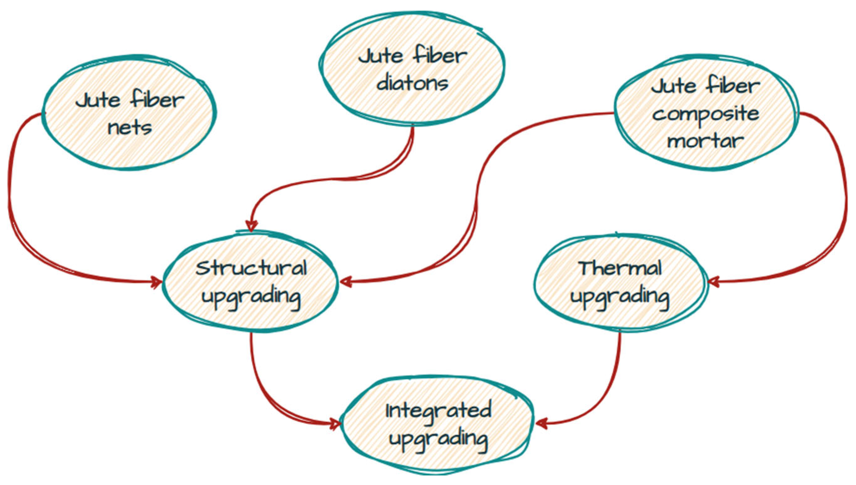
Figure 1. Masonry wall integrated retrofitting scheme.
Buildings 15 02852 g001
Figure 2. (a) Jute fiber and (b) jute fiber threads.
Buildings 15 02852 g002
Figure 3. (a) Diatons and (b) 30 mm chopped fiber.
Buildings 15 02852 g003
Figure 4. (a) Jute fiber net preparation used for tensile strength test (b) the knot used for jute fiber net fabrication and (c) jute fiber net (1 m × 1 m) used for masonry upgrading/retrofitting.
Buildings 15 02852 g004
Figure 5. Jute fiber net: (a) mesh of 2.5 cm × 1.25 cm and (b) preparation for tensile strength tests.
Buildings 15 02852 g005
Figure 6. Tensile strength test.
Buildings 15 02852 g006
Figure 7. Composite mortar samples with various combinations of 1% of jute fiber with different fiber lengths (30 mm, 10 mm, and 5 mm).
Buildings 15 02852 g007
Figure 8. (a) Hollow bricks, (b) un-strengthened masonry wall before upgrading/retrofitting, (c) drilling of holes, (d) insertion of diaton, (e) application of liquid mortar, (f) first thin layer of mortar, (g) application net, (h) zoomed view of jute diaton, (i) fixing of all four diatons to the net, and (j) application of composite mortar.
Buildings 15 02852 g008
Figure 9. Schematic diagram of masonry wall with three hydraulic jacks (A.H) and transducers (T): (a) front view and (b) back view.
Buildings 15 02852 g009
Figure 10. Illustration of a complete 3 load cycles of the retrofitted/upgraded wall.
Buildings 15 02852 g010
Figure 11. (a) Masonry wall with hydraulic jacks and transducers and (b) zoomed view of a transducer installation scheme.
Buildings 15 02852 g011
Figure 12. (a) Biemme TH Climate Chamber, (b) The central wall with un-strengthened hollow brick walls, (a) a masonry wall with dimensions of 0.9 m × 0.7 m × 0.25 m, (c,d) heat flux and temperature sensors mounted on the upgraded masonry wall.
Buildings 15 02852 g012
Figure 13. (a) Application of white color on upgraded masonry wall and (b) DIC test setup.
Buildings 15 02852 g013
Figure 14. Load-displacement curve measured with the diagonal sensor G: (a) two cycles for un-strengthened masonry wall and (b) three cycles for upgraded/retrofitted masonry wall.
Buildings 15 02852 g014
Figure 15. Load-displacement curve measured with the diagonal sensor F: (a) two cycles for un-strengthened masonry wall and (b) three cycles for upgraded/retrofitted masonry wall.
Buildings 15 02852 g015
Figure 16. Load-displacement curve measured with the horizontal sensor F: (a) applied two cycles for un-strengthened masonry wall and (b) three cycles for upgraded/retrofitted masonry wall.
Buildings 15 02852 g016
Figure 17. The shear stress capacity: theoretical [42] vs. experimental.
Buildings 15 02852 g017
Figure 18. Thermal resistances for an upgraded masonry wall.
Buildings 15 02852 g018
Figure 19. Climate chamber measurements: (a) heat flux, (b) internal (room) temperature, and (c) external temperature.
Buildings 15 02852 g019
Figure 20. DIC analysis of the upgraded masonry wall: (a) before start of cracks, (b) point at which first cracks were noted, and (c) point at which maximum crack was obtained.
Buildings 15 02852 g020
Figure 21. The crack trends during the ultimate load cycle of the upgraded masonry wall: (a) applied load vs. (b) crack opening.
Buildings 15 02852 g021
Table 1. Mechanical properties of the raw jute fibers, fiber threads, and diatons [36].
Jute Fiber-Derived ProductsTensile StrengthStrain EnergyMaximum Axial Stain
[MPa][kNmm]
Raw fiber215.10 (4.4%)0.80 (58.9%)0.013 (19.1%)
Threads112.45 (26.2%)1.03 (34.6%)0.07 (11.71%)
Diatons15.50 (20.8%)14.18 (53.9%)0.03 (23.6%)
Value provided in parentheses is CoV.
Table 2. Mechanical properties of jute fiber net of mesh configuration of 2.5 cm × 1.25 cm [10].
StiffnessStrain EnergyMaximum LoadMaximum Displacement
[N/mm][kN.mm][N][mm]
Net7.6 (20.2%)8.8 (39.1%)217.3 (24.8%)72.5 (17.8%)
Value provided in parentheses is CoV.
Table 3. Specification of the SM mortar.
ParameterSpecification
Standard ComplianceUNI EN 998-2 [38]
AppearanceFine powder
Maximum Granulometry2.0 mm
Water Content~18%
Dry Apparent Density1545 kg/m3 ± 3%
Fresh Mortar Density2029 kg/m3 ± 3%
Capillary Water Absorption0.8 kg/(m2·min0.5)
Fire Resistance ClassA1
Chloride Content0.05% Cl
Compressive Strength (28 days)M10 (10 N/mm2) as per EN 998-2
Initial Shear Strength0.3 N/mm2
Thermal Conductivity0.83 W/mK
Recommended Application Temperature+5 °C to +35 °C
Table 4. Selection of mortar–jute fiber proportion [36,37].
PropertyBest ValueIntermediate Value
(Selected Sample)
Worst Value
Flexural Stress MPaSample without jute fiberSample with 1% jute fiber (30 mm)Sample with 2% jute fiber (5 mm)
7.8 (8.5%)5.1 (7.9%)3.6 (10.9%)
Compressive Strength MPaSample without jute fiberSample with 1% jute fiber (30 mm)Sample with 2% jute fiber (5 mm)
32.3 (5.6%)21.8 (5.79%)6.0 (7.5%)
Stain Energy kN.mmSample with 2% jute fiber (30 mm)Sample with 1% jute fiber (30 mm)Sample without jute fiber
2.7 (34.8%)0.6 (67.0%)0.5 (13.9%)
Thermal
Conductivity
W/mKSample with 1% jute fiber (5 mm)Sample with 1% jute fiber (30 mm)Sample without jute fiber
0.4 (7.6%)0.5 (5.0%)0.8 (3.9%)
Value provided in parentheses is CoV.
Table 5. Material specification used for the masonry wall construction.
Non-Reinforced Structural Masonry Wall (Reference)Structural Masonry Wall SampleNon-Reinforced Thermal Masonry Wall (Reference)Thermal Masonry Wall Samples
WallWall dimension1 m
×1 m
×0.25 m
1 m
×1 m
×0.25 m
0.9 m
×0.7 m
×0.25 m
0.9 m
×0.7 m
×0.25 m
Mortar (see Section 2.4 and [37])Mortar type SMSMSMSM
Net (see Section 2.3 and [10])Number of nets-2 -2
Number of nets applied on each side-1-1
Net configuration-2.5 cm × 1.25 cm-2.5 cm × 1.25 cm
Net dimension-1 m × 1 m-0.9 m × 0.7 m
Diaton (See Section 2.2 and [36])Number of diations -4-4
Mortar (see Section 2.4 and [38])Composite mortar composition-1% jute fiber (30 mm) with respect to the dry mortar (SM) mass-1% jute fiber (30 mm) with respect to the dry mortar (SM) mass
Table 6. The climate chamber pre-set conditions.
External Ambient Conditions (Cold Side)Internal Room Conditions (Hot Side)
Temperature (°C)220
Humidity (RH%)5050
Ventilation (m/s)101
Table 7. Comparison between NFTRM-upgraded masonry wall vs. non-upgraded un-strengthened masonry wall.
Un-Strengthened Masonry WallNFTRM-Upgraded/Retrofitted Masonry Wall
Load cycleCollapse loadCorresponding displacementCollapse loadCorresponding displacement
kNmmkNmm
Ultimate load cycle3511.1523631.27
Table 8. All known, considered, and calculated data related to the unreinforced masonry wall.
The top fixed load on the masonry wall (set applied value)Ftop39.84kN
Length of the masonry wallH1000mm
Height of the masonry walll1000mm
Thickness of the masonry wallt200mm
Stress due to gravity load *σ00.1992MPa
Correction coefficient of the stresses in the cross-sectionP1.5
Experimental maximum horizontal forceVtexp35.41kN
Calculated share stress capacity due to gravity load **τ0d0.12269 (see Figure 17)MPa
* Calculated using Equation (2). ** Calculated using Equation (3).
Table 10. The shear capacity of the upgraded wall.
Maximum Experimental Horizontal Force (Measured)Vt,R.exp.235.47kN
Table 11. NFTRM contributions towards the upgraded masonry wall strength.
Total NFTRM contribution * V t , f . TOTAL 197.46 kN
Contribution of a single NFTRM system package ** V t , f 98.73kN
* Calculated using Equation (9). ** Calculated using Equation (10).
Table 13. Thermal resistance for each component layer of the tested masonry wall assembly.
Layers ConsideredResistances
Indoor *Rin.0.040m2K/W
Composite mortar layerR1.10.050m2K/W
Net + diatons + mortar layerR2.10.116m2K/W
Hollow brick resistanceRwall0.396m2K/W
Net + diatons + mortar layerR2.20.116m2K/W
Composite mortar layerR1.20.050m2K/W
Ambient/outdoor *Ramb.0.13m2K/W
* according to UNI EN 6946:2018 [43].
Table 14. Thermal transmittance values.
Reference Masonry WallNFTRM-Upgraded/Retrofitted Masonry Wall
W/m2KW/m2K
1.7681.114
Table 15. Integrated behavior of the NFTRM-upgraded masonry wall compared with other TRM-upgraded/retrofitted masonry walls.
Improvement in Structural Property
(Among All Specimens Studied)
Improvement in Thermal Property
(kN)(W/m2K)
Current Project:
NFTRM-upgraded masonry wall sampleThe load-bearing capacity increased by 574.29% when compared with the un-strengthened masonry wall.The thermal transmittance value was reduced by 36.99% when compared with the un-strengthened masonry wall.
Man-made (Glass, basalt, steel etc.) fiber-integrated retrofitting/upgrading
[26]Increment in the peak load (three-point bending tests). No experimental results are available. The improvement in insulation properties is attributed to the presence of EPS.
[27]Increment in the peak load (three-point bending tests).No experimental results are available. The improvement in insulation properties is attributed to the presence of EPS.
[28]Out-of-plane and in-plane tests were performed, and improvements in shear strength and load-bearing capacity were observed, respectively. No experimental results are available. The improvement in insulation properties is attributed to the presence of EPS.
[29]Enhanced peak load (in-plane tests).No experimental results are available. The improvement in insulation properties is attributed to the presence of EPS.
[30]Improvement in shear strength capacity. Improvement in insulation properties (experimental).
[31]Lateral load capacity improved.No experimental results are available.
[32]Increment in shear strength (out-of-plane tests) and improvement in peak load (in-plane tests).No experimental results are available. The improvement in insulation properties is attributed to the presence of EPS.
[33]Increment in the maximum peak load (out-of-plane).In this case, the thermal transmittance of the masonry walls was calculated based on the materials’ thermal conductivity values.
Table 12. The ultimate strength of the upgraded/retrofitted masonry wall.
Ultimate strength σ u , f 5.88MPa
Disclaimer/Publisher’s Note: The statements, opinions and data contained in all publications are solely those of the individual author(s) and contributor(s) and not of MDPI and/or the editor(s). MDPI and/or the editor(s) disclaim responsibility for any injury to people or property resulting from any ideas, methods, instructions or products referred to in the content.