1. Introduction
The shear damage mechanism of reinforced concrete beams is a complex problem involving multiple shear force transfer mechanisms, such as aggregate interlock behavior, residual tensile stress in the fracture process zone, contributions from the uncracked compression zone, and dowel action [
1,
2]. Due to its complexity, most existing formulas for the calculation of the shear capacity of reinforced concrete beams are semi-theoretical and semi-empirical. Meanwhile, most of the calculation methods for T-beam shear capacity are developed based on rectangular beams, which may lead to the overly conservative calculation of shear capacity in T-section beams [
3].
All things being equal, T-beams are more favorable than rectangular-section beams for transferring pressure in the concrete compression zone due to the presence of flanges [
4]. Considering the effect of flanges on the shear capacity of beams, both domestic and international scholars have proposed different correction formulas. Qi Jia-Nan et al. [
3] corrected the effective shear region of the flange by considering the height of the compression zone and calculating 157 collected T-beams; the results showed that the formula was in good agreement with the test values. Feng Hao-Xiong et al. [
5] considered the width of the compression zone of reinforced concrete T-beams and derived the formula for calculating the shear capacity of reinforced concrete T-beams considering the effective width of the flanges and compared it with the code results. The calculation results show that the calculation method is in good agreement with the test results. Giaccio et al. [
6] studied and calculated the effect of flange geometry on the shear strength of reinforced concrete T-beams and showed that increasing the ratio of flange width to web width helps to increase the shear capacity of the beams when the ratio of flange height to effective height is greater than 0.25. Liu et al. [
7] collated the results from a number of scholars [
8,
9,
10,
11,
12] for T-beam formulas considering flange and collected 233 beams for validation and comparison. The results show that each of the five models has its own advantages and disadvantages. Deifalla et al. [
13] developed a bending-shear-torsion interaction capacity model for FRP-strengthened beams, while Zeng et al. [
14] and Liu et al. [
15] proposed shear capacity formulas for FRP-UHPC composite beams and a modified shear model for UHPC-strengthened beams, respectively, demonstrating good agreement between theoretical calculations and experimental results [
13,
14,
15]. These studies provide theoretical foundations for the capacity calculation of different strengthening techniques. Zhang et al. [
16] proposed a calculation method applicable to one-way slab and beams of Fiber-Reinforced Polymer composites (FRP) and streamlined the calculation process by utilizing the collected test data. Comparisons show that the proposed method outperforms design codes in terms of discrete type and accuracy.
With the development of computer arithmetic and the improvement of test data, scholars began to focus on the use of machine learning algorithms in concrete members. Common machine learning algorithms such as Regression Decision Tree (DT), regression forest (RF), and artificial neural network (ANN) have been used to solve the regression problem. Rahman et al. [
17] collected 507 sets of steel-fiber concrete beams and selected 11 machine learning algorithms to train and rank the features using feature importance. Chou et al. [
18] used the Smart Firefly Algorithm (SFA) to optimize the hyperparameters of Least Squares Support Vector Regression (LSSVR). The results show that the proposed model outperforms other models in predicting the shear strength of a wide range of reinforced concrete beam types. Yu et al. [
19] used artificial neural networks and regression forests to calculate the shear capacity of recycled aggregate concrete beams. The results showed that both models were more accurate in predicting the shear bearing capacity. Castillo et al. [
20] trained three machine learning algorithms using 1436 sets of shear test data for reinforced concrete beams and slabs, and the results showed that Gaussian Process Regression had the most accurate results among the three algorithms. Zhang et al. [
21] developed a random forest model to predict the shear strength of reinforced concrete beams and collected 194 sets of data for reinforced concrete beams with web reinforcement and 1849 sets of data for reinforced concrete beams without web reinforcement. The results show that the trained model has a small error for the calculation of shear capacity in reinforced concrete beams. This study focuses on the multi-mechanism coupling characteristics of shear capacity in beams without stirrups. It selects a Tree model with strong interpretability (DT, RF) and high-performance gradient boosting frameworks (XGBoost (py-xgboost version: 1.7.3), LightGBM (version: 3.3.5 from lightgbm/python-package)), combined with deep learning (ANN), to investigate the regression predictive ability under small sample data. Through feature importance analysis, the dominant influence of concrete strength on bearing capacity is revealed, providing a basis for the parameter optimization of mechanical models.
In this study, based on the assumptions of the crack-slip model, a calculation method for the shear capacity of unreinforced beams without web reinforcement is proposed, considering the contribution of the flange and separating the contribution of the compression zone from that of the tension zone. This method aims to explicitly account for the strengthening effect of flanges through physical mechanisms. Using the calculation method proposed in this study, the differences between the calculation results and the test results are compared; in addition, the machine learning method is used to perform regression analysis on the collected dataset. The results show that the calculation method is able to better predict the shear capacity of concrete T-beams without web reinforcement; machine learning is more accurate for predicting the shear capacity of reinforced concrete beams without web reinforcement, and the selected features significantly contribute to calculating the shear capacity of concrete beams.
2. Shear Capacity of Reinforced Concrete Beams Considering the Influence of Flanges
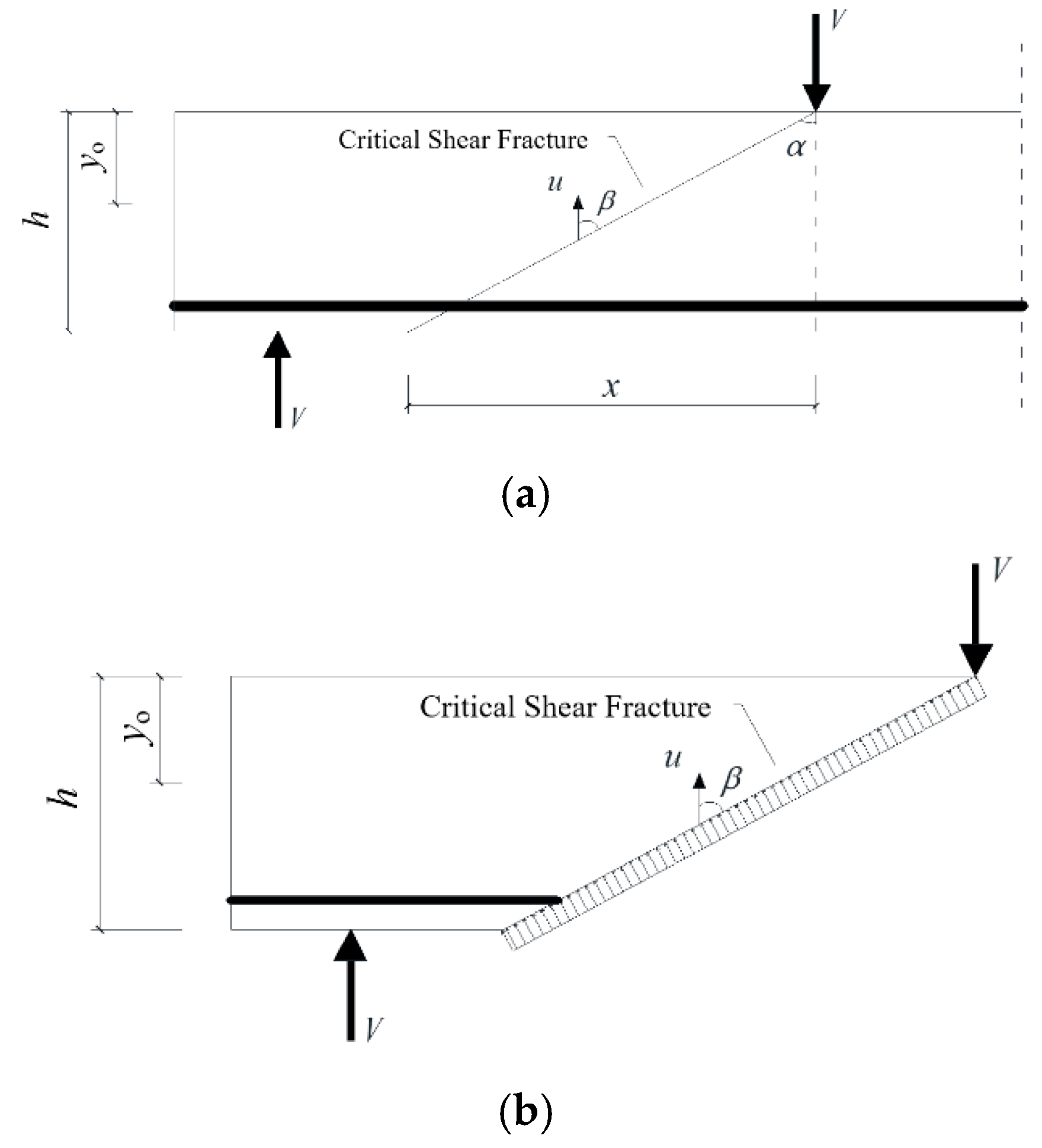
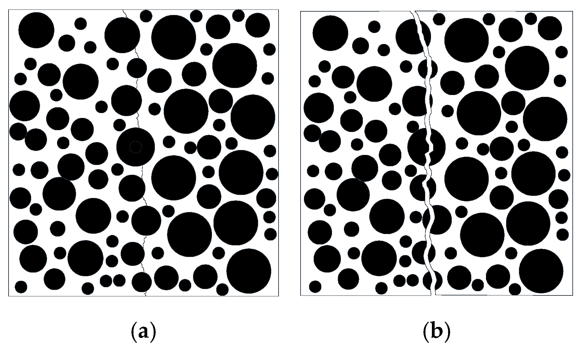
As shown in
Figure 1, based on the assumption of the crack slip model, the cracking path of the main crack is a straight line from the cracking point to the loading point [
22]. If a crack is a kind of material, the failure of the beam is controlled by the material failure at the main crack.
Under this assumption, the shear capacity of the beam can be determined by the following equation [
23]:
In the above formula, is the shear capacity of the beam; is the tensile strength of the cracked material; and . In the above formula, is the tensile strength of concrete, is the height of the beam section. is the width of the beam section, is the effective height of the section, x is the location of the beam crack initiation, and is the distance from the loading point to the support.
For this model, the crack initiation location
x can be approximated using the following equation [
23]:
In practice, the state of cracking in the tension zone is not different from that in the compression zone. For slender beams, in the compression zone, the contribution of cracks to the shear capacity can be approximated using the tensile strength of concrete [
24]; however, in the tensile zone, the width of the cracks increases, resulting in a decrease in the capacity provided by aggregate interlock behavior in the tensile zone, and the effect of the width of the cracks on the contribution of aggregate interlock behavior needs to be considered. At the same time, the contribution of the flange to the shear bearing capacity is mainly concentrated in the compression zone, so the influence of the flange on the shear bearing capacity is only considered in the compression zone.
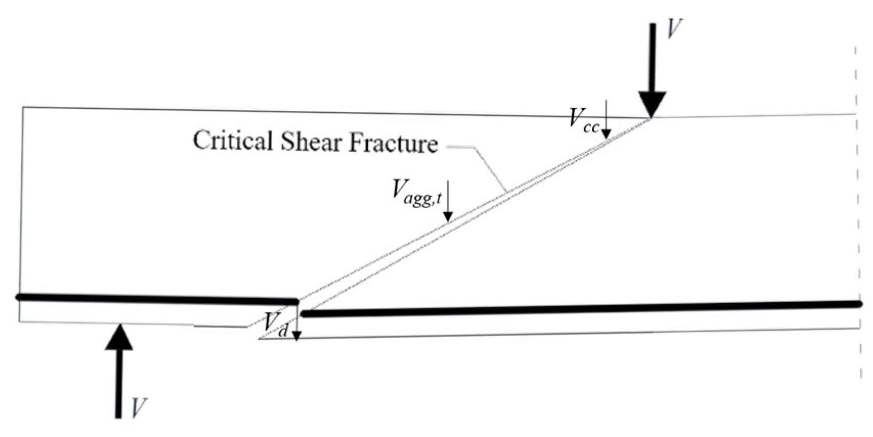
In summary, the shear bearing capacity of the beam without a web under this theory can be expressed as Equation (3). The schematic diagram is shown in
Figure 2.
In the above formula,
is the shear capacity of the beam;
is the contribution of cracks in the pressure zone;
is the contribution of the Dowel action;
is the contribution of aggregate interlock behavior in the tension zone; and
is a correction coefficient client used to account for size effects [
25]:
.
2.1. Contribution of the Compression Zone
In order to consider the influence of the T-beam flange on the shear capacity of reinforced concrete beams, the shear capacity contributed by the compression zone is considered separately here. The height of the compression zone is calculated according to the following formula [
26]:
In the above formula, is the ratio of the elastic modulus of steel and concrete; is the reinforcement ratio of longitudinal reinforcement in the rectangular section, ; is the width of the web; and is the cross-sectional area of the longitudinal reinforcement.
For slender beams (the ratio of shear span to effective depth
), the concrete shear capacity contribution in the compression zone exists in relation to the concrete tensile strength, as shown in the following equation [
24]:
In the above formula,
is the angle between the crack and the vertical line,
;
is the height of the pressure zone;
is the compressive strength of the concrete cylinder,
= 0.8
; and
is the cubic compressive strength of concrete,
[
27].
2.2. The Contribution of Aggregate Interlock Behavior in the Tension Zone
Aggregate interlock behavior, in which the parts protruding from the two surfaces on either side of the crack are in contact with each other to provide the shear bearing capacity, is affected by the crack surface roughness and crack width; this shear transfer mechanism plays a major role in reinforced concrete beams without web reinforcement [
27].
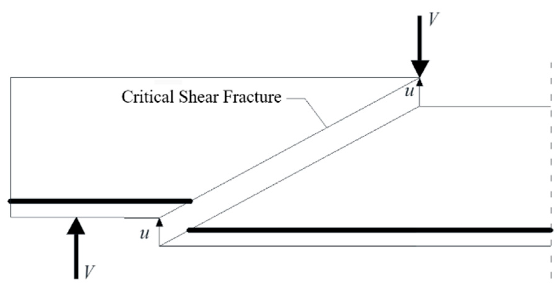
Based on the basic assumptions of the crack slip theory, the shear capacity provided by aggregate interlock behavior needs to be determined using the functional equation. As shown in
Figure 3, Assuming that the relative displacement of the surfaces on either side of the crack is u, the work enacted by the external force at the time of damage is as follows:
In the above formula, is the work enacted by the external force at the time of destruction and is the relative displacement of the surfaces on both sides of the crack and the critical shear crack angle.
Energy dissipation in critical shear cracks at destruction is represented below [
28]:
In the above formula, is the local coordinate axis along the crack length and is the effective value of shear transfer.
By summarizing the work completed by the remaining shear transfer mechanism at the time of damage as
, the contribution of aggregate interlock behavior, based on the functional equation, is calculated as follows:
Solving this results in the following equation:
In the above formula, is the contribution of aggregate interlock behavior to shear bearing capacity.
When the bottom longitudinal reinforcement is sufficiently configured, the relative displacements of the surfaces on both sides of the crack are perpendicular to the horizontal line [
29], and the relative displacements are at an angle to the crack. Meanwhile, this calculation only considers the contribution of aggregate interlock behavior in the tension zone and only integrates the cracks that are in the tension zone.
The simplified calculation of the contribution of aggregate interlock behavior in the tension zone, considering aggregate particle size and crack width, is as follows:
In the above formula,
is the effective compressive strength of concrete,
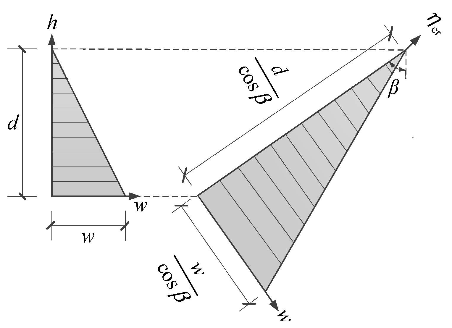
;
is the crack width (see
Figure 4 for the calculation schematic);
is the maximum diameter of the aggregate; and
is the width of the crack at the tensile reinforcement.
According to the literature [
30], the crack width at the tensile reinforcement can be calculated using the following equation. To avoid iterative calculations, it is assumed that the tensile reinforcement is fully yielded as follows:
In the above formula, is the tensile strength of the longitudinal reinforcement; is the elastic modulus of the reinforcement; is the crack spacing; is the amount of lost viscosity; is the bond strength between the concrete and the steel reinforcement; ; is the thickness of the protective layer of concrete; and is the diameter of the tensile reinforcement.
The crack spacing was calculated as follows [
31]:
As shown in
Figure 5, cracks pass through the aggregate at higher concrete strengths or lower aggregate strengths [
32]. Therefore, in high-strength concrete, the correction of aggregate particle size is required:
2.3. Contribution of Dowel Action
At the beginning of the 20th century, Morsch [
33] suggested that longitudinal reinforcement is able to transmit shear forces and, thus, contribute to the shear capacity of reinforced concrete members. This effect is influenced by the thickness of the concrete protective layer and the adhesive properties of the reinforcement to the concrete. This action fails when the concrete protective layer separates along the reinforcement [
34]. According to the literature [
35], the contribution of dowel action is usually only 15–25% of the total shear capacity.
The expression for the contribution of dowel action is as follows:
In the above formula, is the correction coefficient for the tensile strength of concrete, ; is the effective width of the beam at the longitudinal reinforcement, ; is the number of bars; and is the length of the dowel crack, .
2.4. T-Beam Shear Capacity Correction
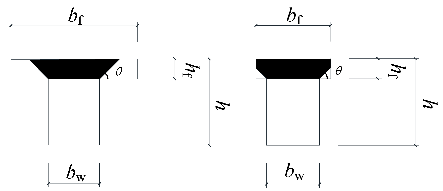
In this study, the findings of Tureyen et al. [
36] were used to consider the effect of T-beam flanges on reinforced concrete beams without web reinforcement. The method assumes the effective flange area of the T-beam, as shown in
Figure 6, using the formula
= 45°.
Then, for a T-section beam, the equation after considering the effective area of the flange is as follows:
In the above formula, is the width of the web; is the flange width; and is the height of the flange.
Considering that the forces transmitted at the different heights and locations of the compression zone are not equal, an increase in the flange leads to an increase in the stiffness of the T-beam [
37]; the material properties cannot be fully utilized, so the area contributed by the flange needs to be partially discounted.
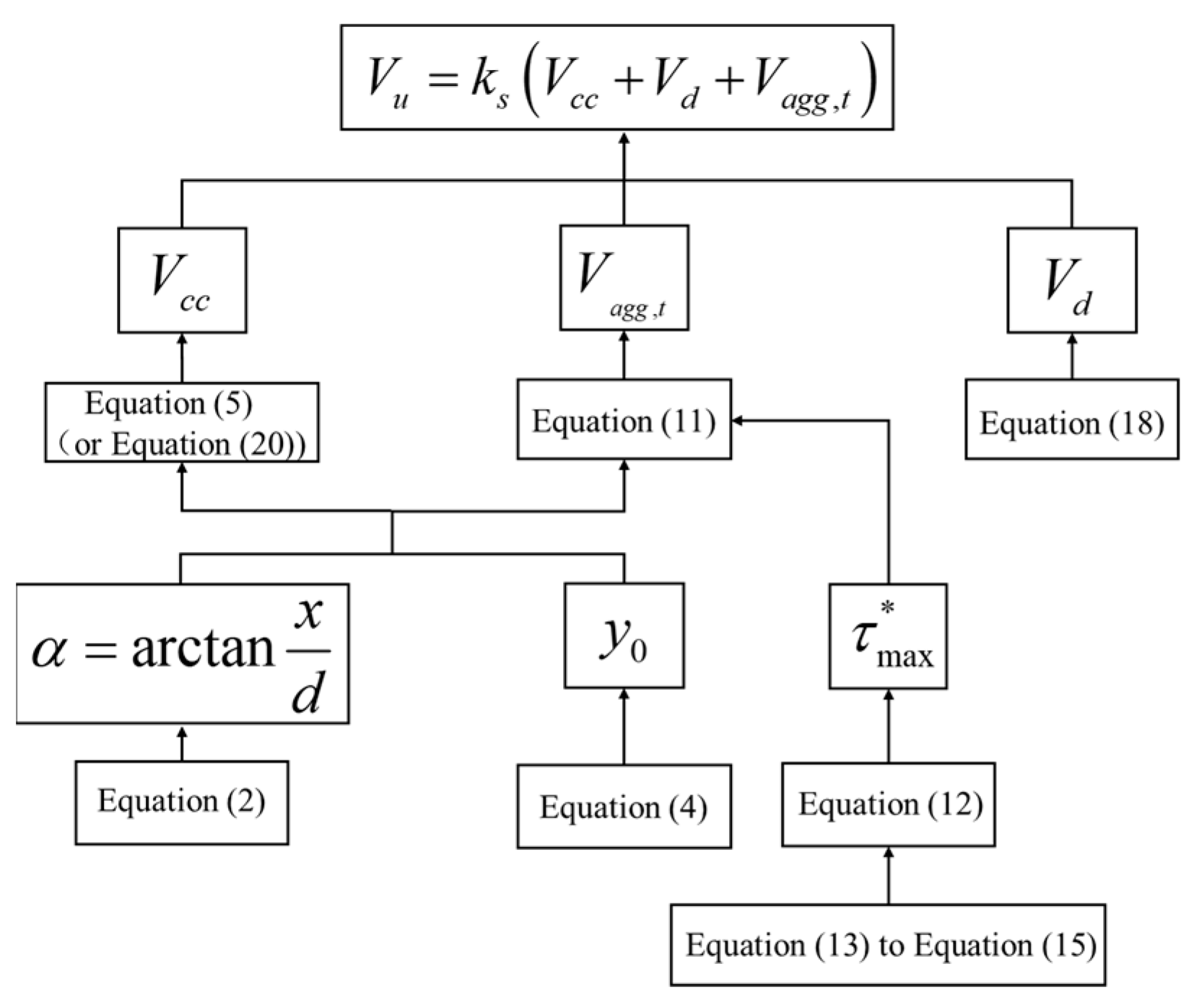
2.5. Calculation of Shear Capacity of Concrete Beams
The calculation process of the concrete beam shear bearing capacity is shown in
Figure 7.
3. Comparative Analysis of Calculation Results
The algorithms proposed in this study are used to validate the rectangular and T-beams with the ratio of shear span to effective depth
in the dataset [
25,
38,
39,
40] and are compared with the results of GB50010-2010 [
41], ACI 318-19 [
42], and EC2 [
43] in the literature [
44] (which has been used in SIA 262 (Swiss Standard for Structural Concrete)) and Zsutty [
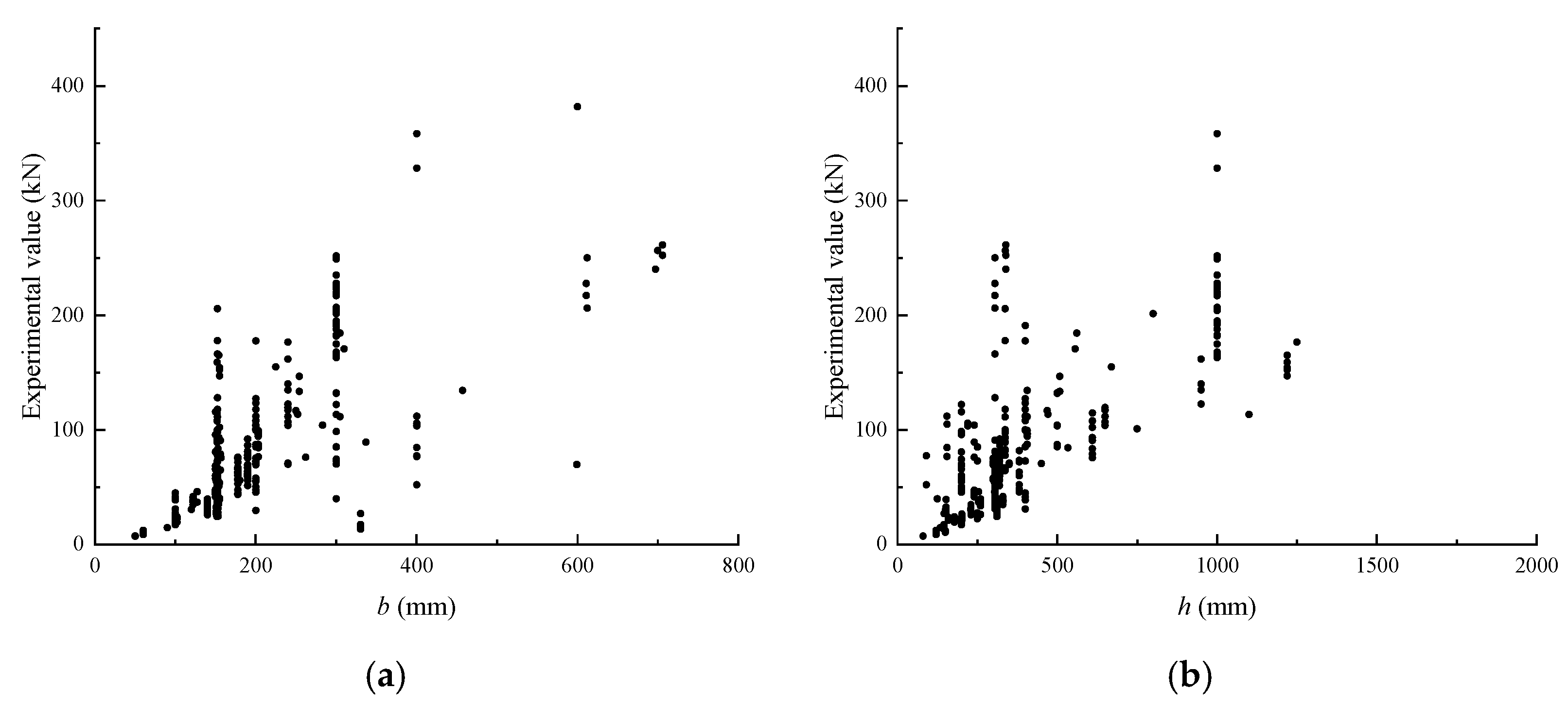
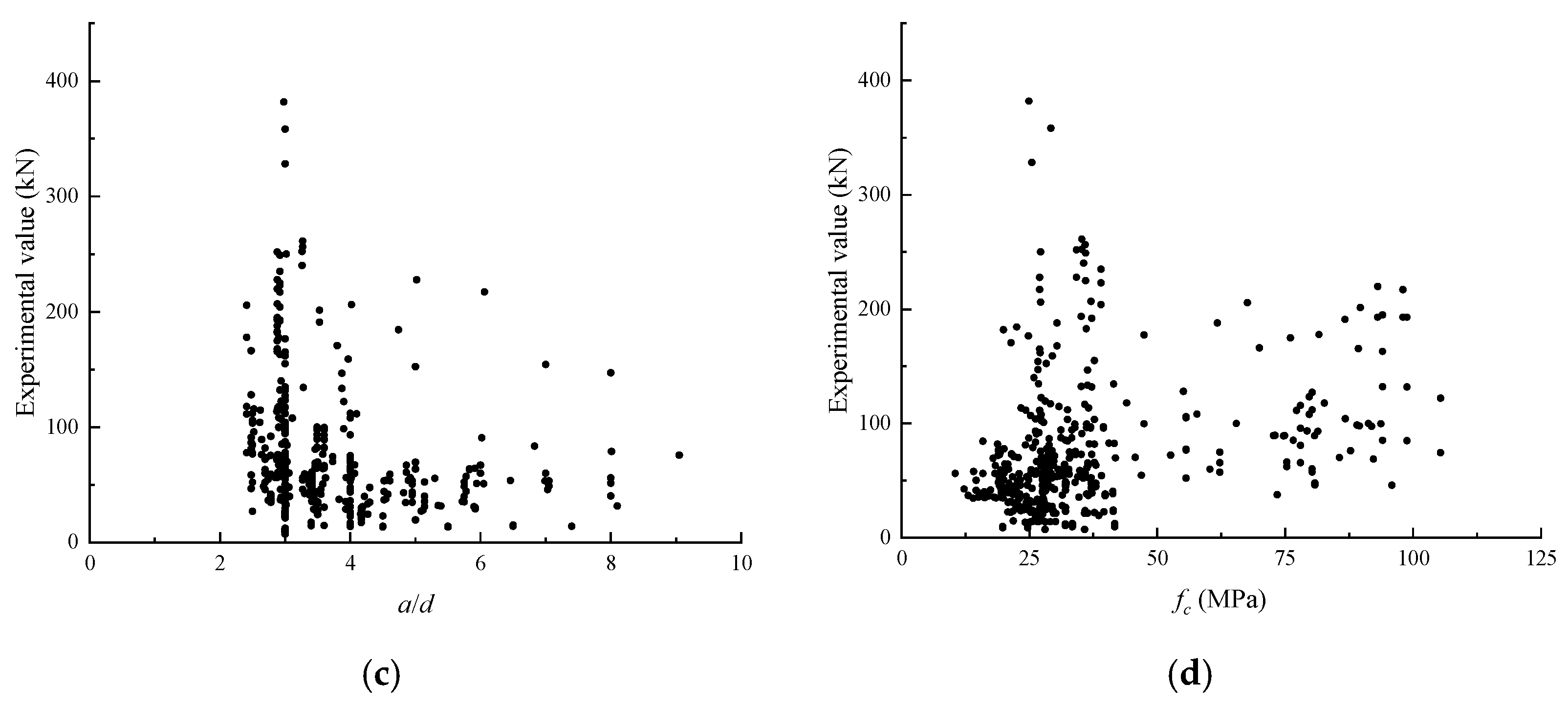
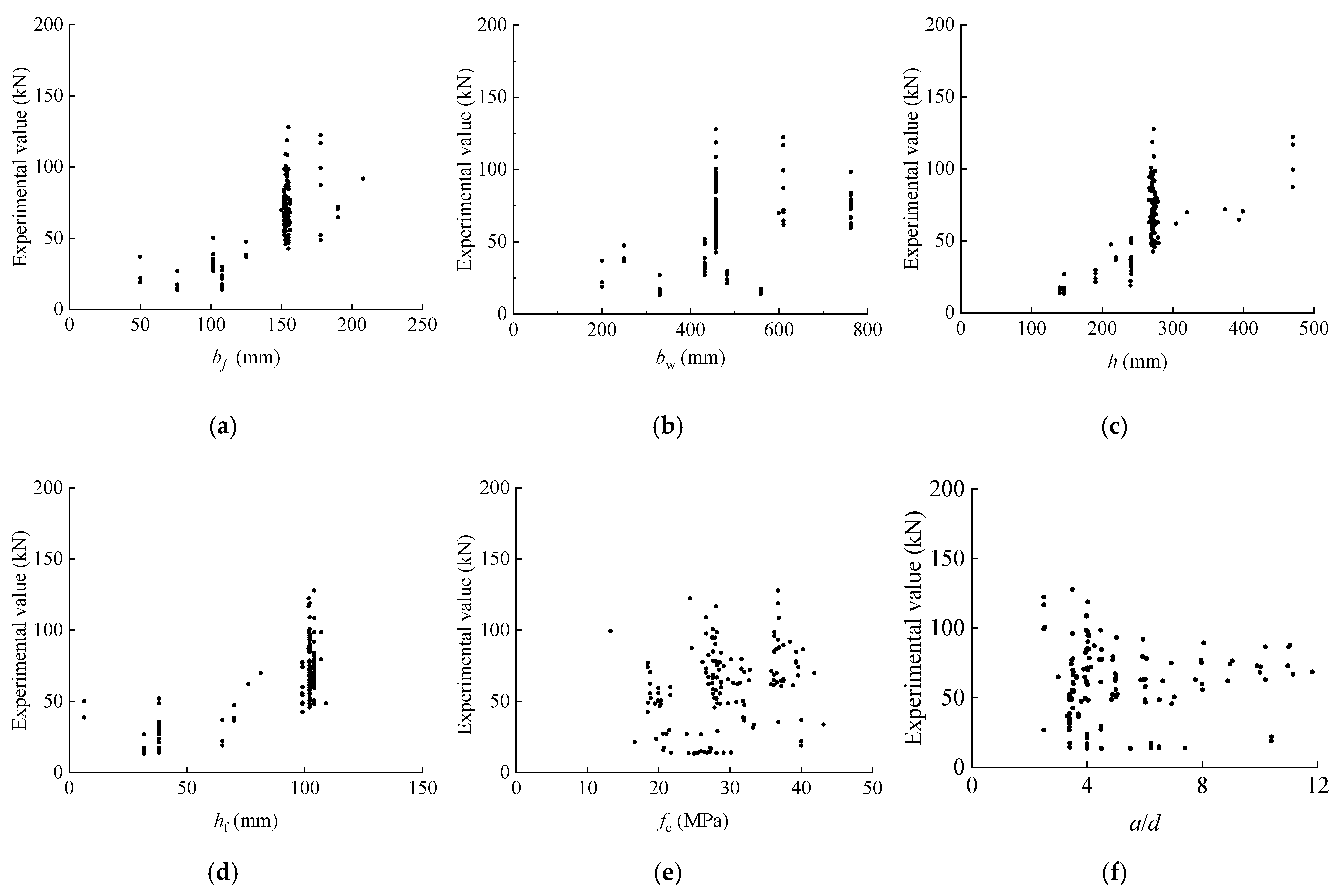
45]. In this case, if there are unrecorded data, the median of the known data is selected for calculation. The composition of the selected dataset is shown in
Table 1 and
Table 2; the distribution of the dataset is shown in
Figure 8 and
Figure 9.
In ACI 318-19, the shear capacity of non-prestressed webless concrete beams is calculated as follows:
In this formula, is the nominal value of shear strength provided by the concrete; is the correction coefficient for dimensional effects, ; is the correction for lightweight aggregate concrete when the concrete density is greater than 2160 kg/m3, ; is the value of the axial force on the member; and is the gross cross-sectional area.
In GB50010-2010, the shear capacity of concrete beams without web reinforcement is calculated as follows:
In this formula, is the section height influence factor, , and is the design value of concrete axial tensile strength.
In EC2, the shear capacity of a concrete beam without web reinforcement is calculated as follows:
In this formula, is the design shear stress and is the corrected concrete strength, when > 40 MPa and = 40 MPa.
In the Critical Shear Cracking Theory (CSCT) proposed in the literature [
44], the shear capacity is calculated as follows for concrete beams without a web:
In this formula,
is the reference strain at the control position, and
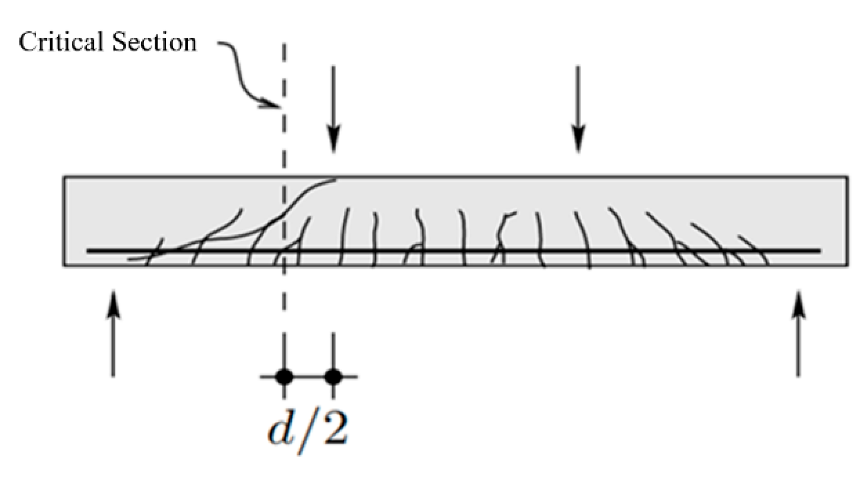
is the bending moment of the control section. For the four-point bending test, the section is located at a distance
from the loading point. The location is shown in
Figure 10.
In the literature [
45], the shear capacity of concrete beams without a web is calculated as follows:
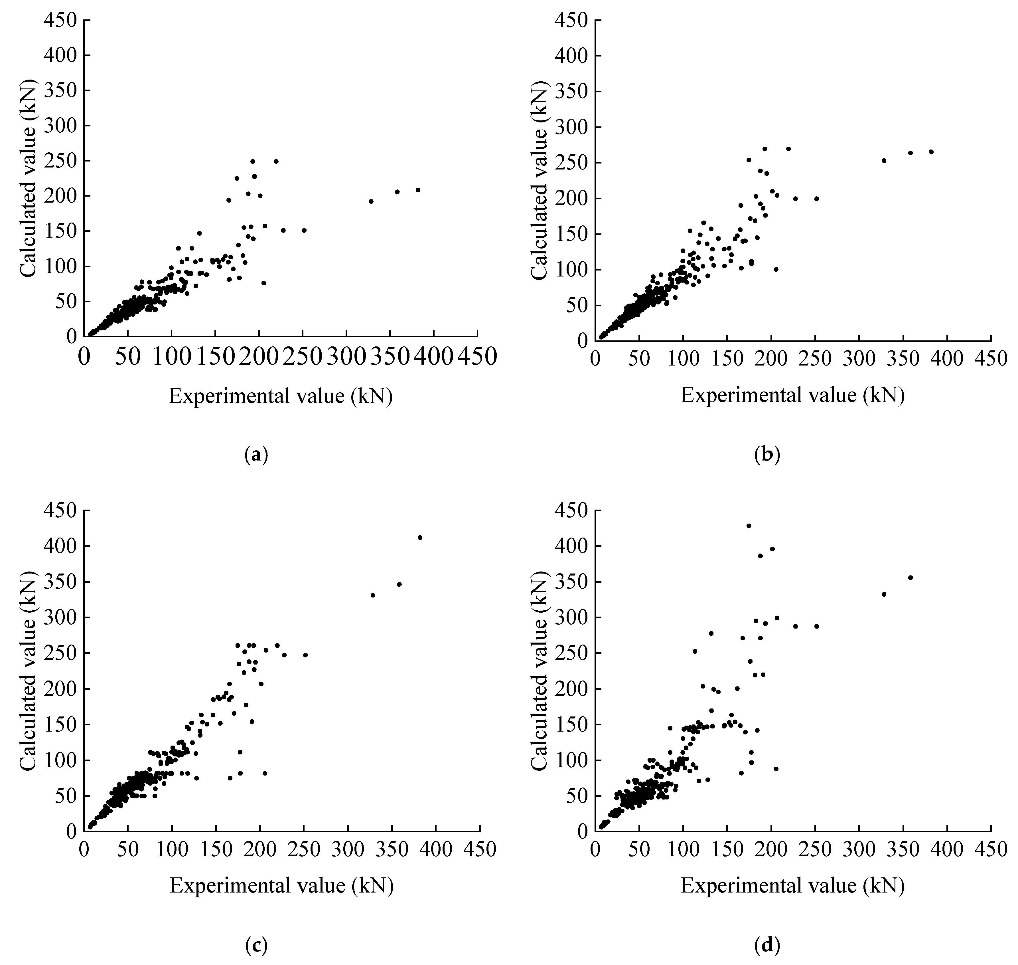
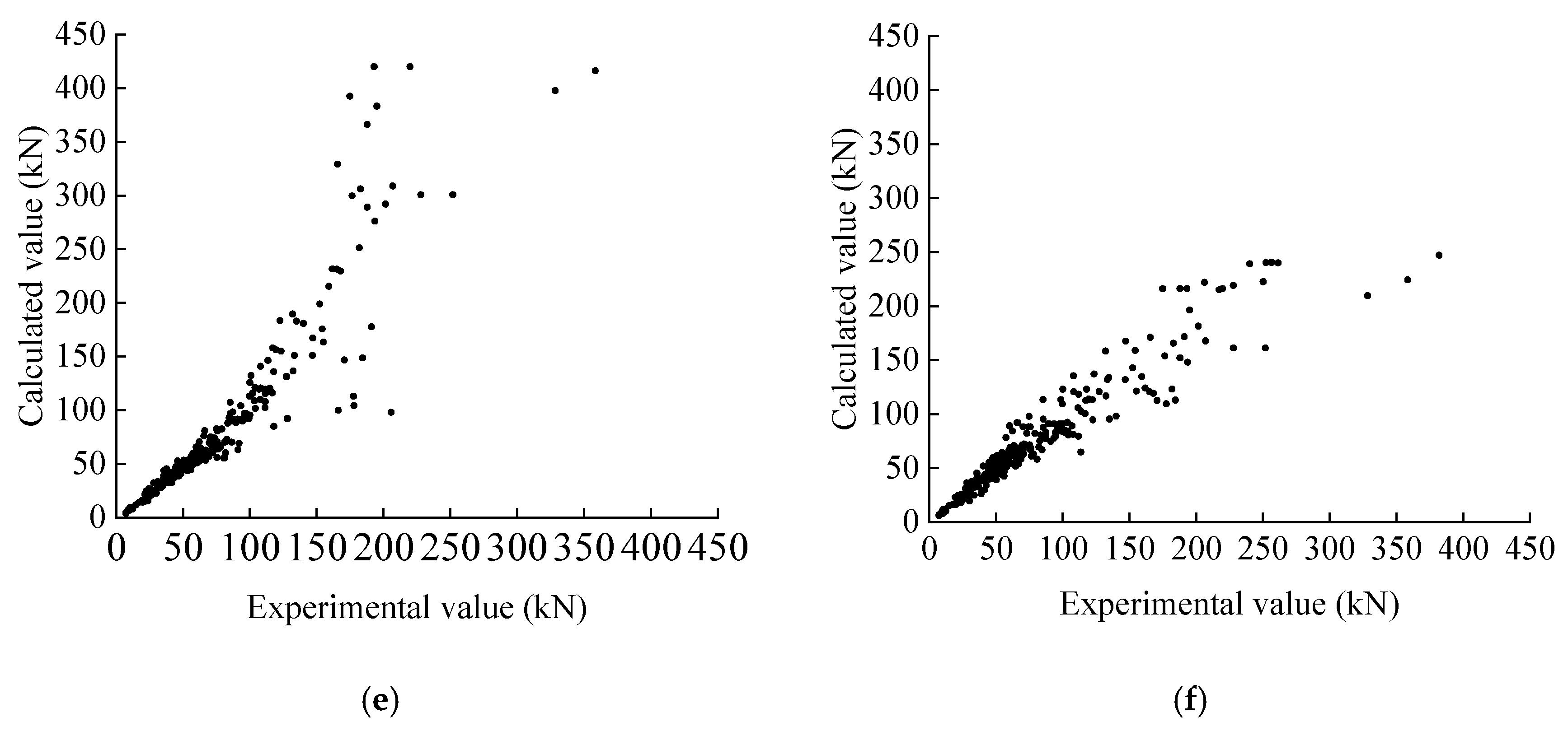
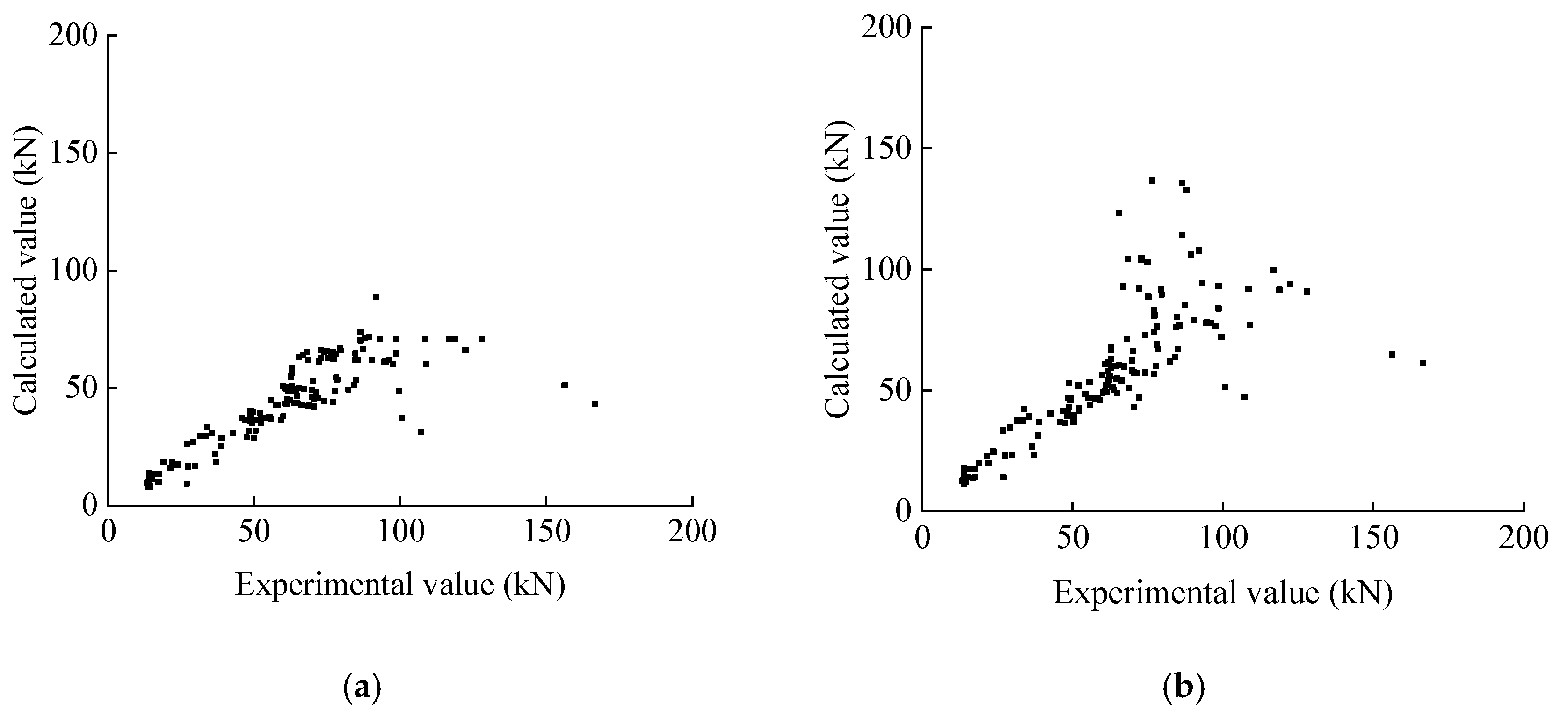
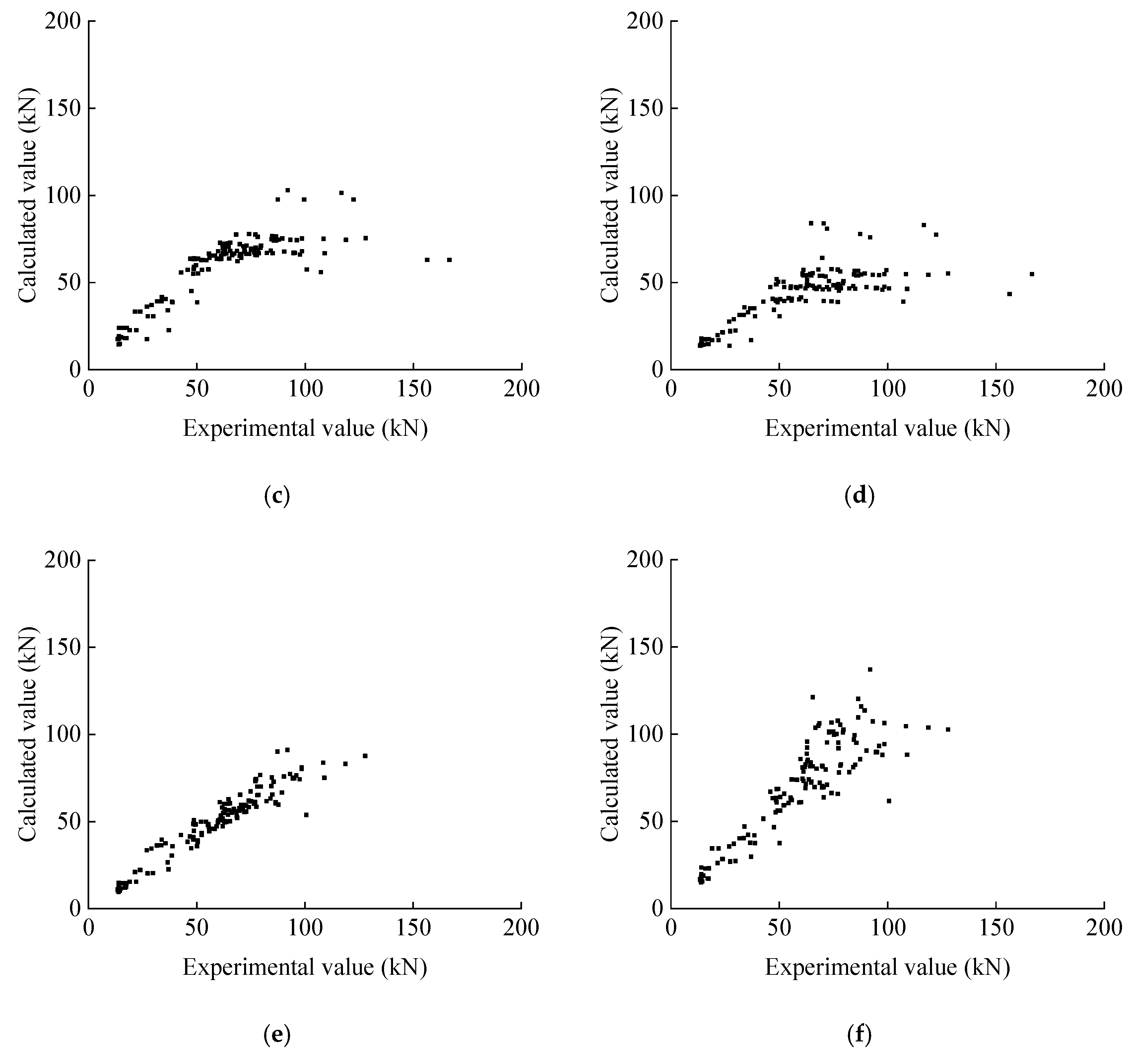
The results of each formula are shown in
Figure 11, and the mean and standard deviation of the ratios of the test values compared to the calculated values are shown in
Table 3.
Comparing the calculation results in
Figure 11, for the calculation formulas proposed by the four codes, the calculation results of the Critical Shear Crack Theory (CSCT) are closest to the real values. The ratio of the experimental value to the calculated value of the formula proposed in this paper has a mean value of 0.9720 and a standard deviation of 0.1468, which can calculate the shear capacity of the beams more accurately; the results of the calculation method proposed in this study are compared to the results of the calculation formulas of the specifications, and the results show that the calculation method proposed in this study is more accurate.
At the same time, using the algorithm proposed in this study and the algorithm of the specification, the collected T-beam shear bearing capacity dataset was calculated; the flange of the calculation results are shown in
Figure 12, and the ratio of the test value to the calculated value of the mean and standard deviation of the test value and the calculated value are shown in
Table 4.
The calculation results in
Figure 12 show that for the formulas proposed in the four codes, the calculation results of the EC2 code are closest to the true values. The ratio of the experimental value to the calculated value of the formula proposed in this study has a mean value of 0.8592 and a standard deviation of 0.1540; compared to the calculation method for the bearing capacity proposed for the rectangle in each code, the algorithm proposed in this study can effectively take into account the contribution of the T-beam flange compared to the bearing capacity.
4. Regression Analysis Based on Machine Learning
In the calculation results shown in
Figure 11 and
Figure 12, for beams with high shear capacity, the results of each formula show different degrees of dispersion. In order to explore the causes of the more discrete data for beams with higher shear bearing capacity, the collected rectangular beam dataset was analyzed with regression using four machine learning algorithms, namely, DT, RF, XGBoost (py-xgboost version: 1.7.3), and LightGBM (version: 3.3.5 from lightgbm/python-package). The purpose of machine learning is not to replace physical models but to serve as a data-driven tool for uncovering latent patterns in data and cross-referencing them with computational results from physical models.
Due to the small amount of data and parameters, a grid search algorithm was used to determine the hyperparameters in this study, and the explained variance score was used to evaluate the performance of the results in the test set.
The explained variance score is a metric for evaluating the model’s prediction variance, and the closer this value is to one, the more accurate the prediction method is in explaining the variance. The algorithm is formulated as follows:
In this formula, represent actual and projected results, respectively. denotes the variance-taking operation.
Because some of the parameters in the dataset had default values, only the following five input parameters were used: .
The final identified hyperparameters and their scores are as follows:
- (1)
Regression Tree algorithm. The maximum depth is eight, the minimum number of samples to be included in the leaf nodes is two, and the minimum number of samples to be split is three. The score is 0.8762.
- (2)
Regression forest algorithm. The number of weak learners is 300, the maximum depth is 11, the minimum number of samples to be included in the leaf node is 1, and the minimum number of samples to be split is 4. The score is 0.9160.
- (3)
LightGBM algorithm. The learning rate is 0.05, the maximum depth of the tree is 5, the minimum number of samples of leaf nodes is 5, the number of weak learners is 300, the number of leaf nodes is 10, the regularization factor of L1 is 0.5, and the regularization factor of L2 is 0.5. The score is 0.9297.
- (4)
XGBoost algorithm. The proportion of features used per tree is 0.8, the learning rate is 0.05, the maximum depth is 3, the minimum sum of sample weights required for node splitting is 1, the number of weak learners is 300, the L1 regularization coefficient is 0, the L2 regularization coefficient is 0.1, and the proportion of samples used per tree is 0.8. The score is 0.9443.
The hyperparameters not mentioned above were taken as default values.
At the same time, an artificial neural network with seven linear layers was built using the deep learning framework Pytorch to compare with the results of the above algorithm. The shape of the network and the number of parameters are shown in
Table 5.
In ANN, we used Relu as the activation function and MESloss as the loss function, with a learning rate of 0.001 and 200 epochs.
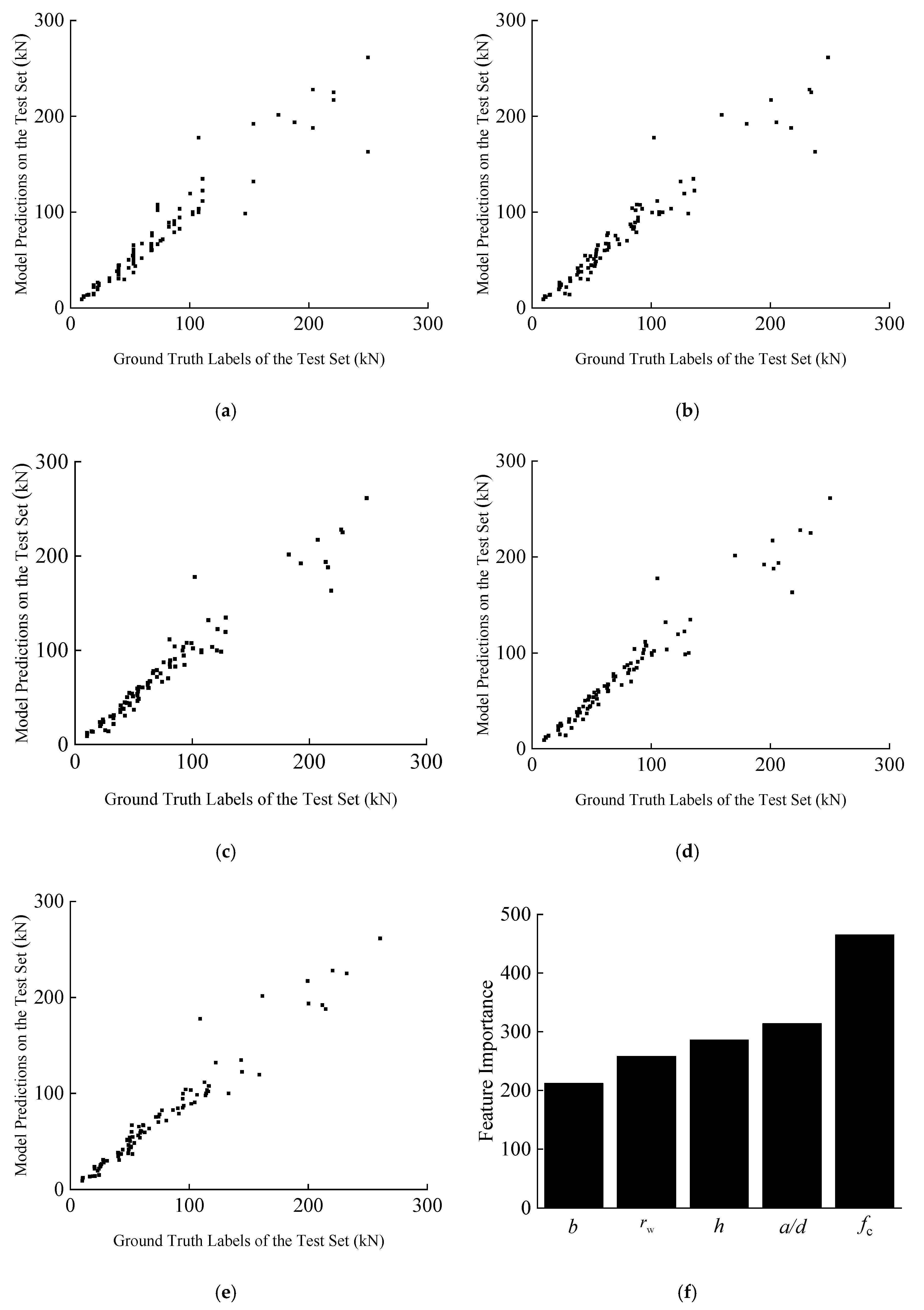
The test set and training set were divided by 0.8:0.2 and computed using the above parameters. The performance of the trained models on the test set is shown in
Figure 13a–e.
Meanwhile, the importance of features for the highest scoring XGBoost model was exported and plotted, and the final result is shown in
Figure 13f.
The results in
Figure 13 show that each algorithm has a good fitting degree even in the case of a small dataset; the calculation results of each algorithm for beams with a higher shear load capacity still have some deviation, which may be due to the fact that some of the shear force transfer mechanisms are changed in the case of higher shear load capacity, or for the brittle failure of the shear capacity test when the loading rate and other experimental factors have a greater impact, resulting in larger fluctuations in test results.
The results in
Figure 13f show that for the shear capacity of beams without web reinforcement, the influence of concrete strength is greater, and the five parameters selected have a significant effect on the shear capacity of beams without web reinforcement.
The main reasons for the differences between machine learning and classical methods are as follows: The core logic of machine learning methods lies in data fitting. They construct the mapping relationship between inputs and outputs by training on a large number of samples, with the objective of model parameters being to minimize the error between predicted values and actual values, which essentially constitutes a statistical capture of the laws governing data distribution. In contrast, classical methods are based on mechanical knowledge: they derive results through rigorous formula deductions by establishing control equations and theoretical models that conform to physical laws, and they are underpinned by a deterministic description of objective mechanical mechanisms. For this reason, on specific datasets, machine learning methods, by virtue of their strong nonlinear fitting capabilities, often yield results that are closer to the measured values.
5. Conclusions
- (1)
The calculation results of the algorithm proposed in this study are in good agreement with the test data of 444 rectangular-section beams and 172 T-beams, and the ratio of the test values to the calculated values has a mean value of 0.9720 and a standard deviation of 0.1468 on the dataset of rectangular beams, while the ratio of the test values to the calculated values has a mean value of 0.8592 and a standard deviation of 0.1540 on the T-beams.
- (2)
A comparison of the calculation results with those of national and international codes shows that the calculation results of each code on rectangular-section beams are in good agreement with the test values; however, for T-section beams, the codes of each country neglected the shear capacity provided by the flanges. The calculation method proposed in this study is more accurate, and the contribution of the flanges to the shear capacity of the concrete beams without web reinforcement can be considered.
- (3)
The results of the collected dataset were validated using machine learning algorithms, and the results show that machine learning is more accurate in predicting the shear capacity of reinforced concrete beams without web reinforcement, and that the selected features contribute significantly to the shear capacity of concrete beams. More discrete data occurred at higher shear load capacities, which is the same phenomenon observed for the results of each computational method. This supports the dominant role of key parameters in the physical model of crack slip.
Author Contributions
Conceptualization, P.T.; methodology, P.T. and Y.H; validation, K.W., J.W. and Z.T.; formal analysis, Y.H. and K.W.; investigation, J.W.; resources, Z.T. and E.X.; data curation, Y.H. and K.W.; writing—original draft preparation, P.T. and Y.H.; writing—review and editing, Y.H.; visualization, K.W.; funding acquisition, P.T. All authors have read and agreed to the published version of the manuscript.
Funding
This research was funded by the Natural Science Basis Research Plan in Shaanxi Province of China (Grant No. 2025JC-YBMS-390), and the Qinchuangyuan Innovation Driving Platform-Future City Construction and Management Innovation Joint Research Center unveiled provided the fund project (2024WHZ0225).
Data Availability Statement
The data will be made available on request.
Acknowledgments
This work was supported by the Natural Science Basis Research Plan in Shaanxi Province of China (Grant No. 2025JC-YBMS-390), and the Qinchuangyuan Innovation Driving Platform-Future City Construction and Management Innovation Joint Research Center provided the fund project (2024WHZ0225).
Conflicts of Interest
Author Penggang Tian was employed by the company Shaanxi Construction Engineering Holding Group Science and Technology Innovation of Future City Co., Ltd., SCEGC-XITU Joint Research Center for Future City Construction and Management Innovation, Shaanxi Academy of Building Science Co., Ltd. Authors Kai Wang, Jiajia Wang and Zhiheng Tian were employed by the company Shaanxi Construction Engineering Holding Group Science and Technology Innovation of Future City Co., Ltd., SCEGC-XITU Joint Research Center for Future City Construction and Management Innovation. The remaining authors declare that the research was conducted in the absence of any commercial or financial relationships that could be construed as a potential conflict of interest.
References
- Joint ASCE-ACI Task Committee 426 on Shear and Diagonal Tension of the Committee on Masonry and Reinforced Concrete of the Structural Division. The shear strength of reinforced concrete members. J. Struct. Div. 1973, 99, 1091–1187. [Google Scholar] [CrossRef]
- Ramirez, J.A.; French, C.W.; Adebar, P.E.; Hsu, T.T.C.; Rajagopalan, K.S.; Bonacci, J.F.; Klein, G.J.; Reineck, K.H.; Collins, M.P.; Krauthammer, T.; et al. Recent approaches to shear design of structural concrete. J. Struct. Eng. 1998, 124, 1375–1417. [Google Scholar] [CrossRef]
- Qi, J.; Wang, J. Shear strength of reinforced concrete T-beams considering the effect of flange. J. Southeast Univ. (Nat. Sci. Ed.) 2019, 49, 638–644. [Google Scholar]
- Yi, W. Experimental and Theoretical Research on Concrete Structures; China Science Press: Beijing, China, 2012. [Google Scholar]
- Feng, H.; Yi, W. Shear strength of reinforced concrete T beams considering effective flange width. J. Jiangsu Univ. (Nat. Sci. Ed.) 2016, 37, 462–466. [Google Scholar]
- Giaccio, C.; Al-Mahaidi, R.; Taplin, G. Experimental study on the effect of flange geometry on the shear strength of reinforced concrete T-beams subjected to concentrated loads. Can. J. Civ. Eng. 2002, 29, 911–918. [Google Scholar] [CrossRef]
- Liu, J.; Gao, Z. A comparative study of models for shear strength of reinforced concrete T-beams. Structures 2022, 35, 922–930. [Google Scholar] [CrossRef]
- Placas, A.; Regan, P.E. Shear failure of reinforced concrete beams. J. Proc. 1971, 68, 763–773. [Google Scholar]
- Ribas Gonzalez, C.R.; Fernández Ruiz, M. Influence of flanges on the shear-carrying capacity of reinforced concrete beams without web reinforcement. Struct. Concr. 2017, 18, 720–732. [Google Scholar] [CrossRef]
- Zararis, I.P.; Karaveziroglou, M.K.; Zararis, P.D. Shear strength of reinforced concrete T-beams. ACI Struct. J. 2006, 103, 693–700. [Google Scholar] [PubMed]
- Cladera, A.; Marí, A.; Ribas, C.; Bairán, J.; Oller, E. Predicting the shear–flexural strength of slender reinforced concrete T and I shaped beams. Eng. Struct. 2015, 101, 386–398. [Google Scholar] [CrossRef]
- Kotsovou, G.M.; Cotsovos, D.M. Shear failure criterion for RC T-beams. Eng. Struct. 2018, 160, 44–55. [Google Scholar] [CrossRef]
- Deifalla, A.; Ghobarah, A. Strengthening RC T-beams subjected to combined torsion and shear using FRP fabrics: Experimental study. J. Compos. Constr. 2010, 14, 301–311. [Google Scholar] [CrossRef]
- Zeng, J.J.; Pan, B.Z.; Fan, T.H.; Zhuge, Y.; Liu, F.; Li, L.J. Shear behavior of FRP-UHPC tubular beams. Compos. Struct. 2023, 307, 116576. [Google Scholar] [CrossRef]
- Liu, T.; Charron, J.P. Experimental study on the shear behavior of UHPC-strengthened concrete T-beams. J. Bridge Eng. 2023, 28, 04023064. [Google Scholar] [CrossRef]
- Zhang, T.; Oehlers, D.J.; Visintin, P. Shear strength of FRP RC beams and one-way slabs without stirrups. J. Compos. Constr. 2014, 18, 04014007. [Google Scholar] [CrossRef]
- Rahman, J.; Ahmed, K.S.; Khan, N.I.; Islam, K.; Mangalathu, S. Data-driven shear strength prediction of steel fiber reinforced concrete beams using machine learning approach. Eng. Struct. 2021, 233, 111743. [Google Scholar] [CrossRef]
- Chou, J.S.; Pham, T.P.T.; Nguyen, T.K.; Pham, A.D.; Ngo, N.T. Shear strength prediction of reinforced concrete beams by baseline, ensemble, and hybrid machine learning models. Soft Comput. 2020, 24, 3393–3411. [Google Scholar] [CrossRef]
- Yu, Y.; Zhao, X.; Xu, J.; Chen, C.; Deresa, S.T.; Zhang, J. Machine learning-based evaluation of shear capacity of recycled aggregate concrete beams. Materials 2020, 13, 4552. [Google Scholar] [CrossRef] [PubMed]
- Castillo, R.; Okumus, P.; Khorasani, N.E.; Chandola, V. Machine Learning for Shear Strength of Reinforced Concrete Beams. ACI Struct. J. 2022, 119, 83–94. [Google Scholar] [CrossRef]
- Zhang, J.; Sun, Y.; Li, G.; Wang, Y.; Sun, J.; Li, J. Machine-learning-assisted shear strength prediction of reinforced concrete beams with and without stirrups. Eng. Comput. 2022, 38, 1293–1307. [Google Scholar] [CrossRef]
- Nielsen, M.P.; Hoang, L.C. Limit Analysis and Concrete Plasticity; CRC Press: Abingdon, UK, 2016. [Google Scholar]
- Zhang, J.P. Serie: Strength of Cracked Concrete, Part 1: Shear Strength of Conventional Reinforced Concrete Beams, Deep Beams, Corbels, and Prestressed Reinforced Concrete Beams Without Shear Reinforcement; Danmarks Tekniske Universitet: Lyngby, Denmark, 1994. [Google Scholar]
- Choi, K.K.; Kim, J.C.; Park, H.G. Shear strength model of concrete beams based on compression zone failure mechanism. ACI Struct. J. 2016, 113, 1095–1106. [Google Scholar] [CrossRef]
- Zararis, P.D.; Papadakis, G.C. Diagonal shear failure and size effect in RC beams without web reinforcement. J. Struct. Eng. 2001, 127, 733–742. [Google Scholar] [CrossRef]
- Muttoni, A.; Fernández Ruiz, M. Shear strength of members without transverse reinforcement as function of critical shear crack width. ACI Struct. J. 2008, 105, 163–172. [Google Scholar] [CrossRef]
- Walraven, J.C. Fundamental analysis of aggregate interlock. J. Struct. Div. 1981, 107, 2245–2270. [Google Scholar] [CrossRef]
- Autrup, F.; Joergensen, H.B. Shear capacity of RC members without shear reinforcement: A modified crack sliding model. Eng. Struct. 2021, 239, 112147. [Google Scholar] [CrossRef]
- Kragh-Poulsen, J.C.; Nielsen, M.P.; Goltermann, P. Shear strength of straight concrete members without shear reinforcement. Reassessment of the effectiveness factors used in the crack sliding theory. Struct. Concr. 2020, 21, 966–982. [Google Scholar] [CrossRef]
- Vecchio, F.J.; Collins, M.P. The modified compression-field theory for reinforced concrete elements subjected to shear. ACI Struct. J. 1986, 83, 219–231. [Google Scholar]
- Reineck, K.H. Ultimate shear force of structural concrete members without transverse reinforcement derived from a mechanical model (SP-885). Struct. J. 1991, 88, 592–602. [Google Scholar]
- Huber, P.; Huber, T.; Kollegger, J. Investigation of the shear behavior of RC beams on the basis of measured crack kinematics. Eng. Struct. 2016, 113, 41–58. [Google Scholar] [CrossRef]
- Mörsch, E. Der Eisenbetonbau, seine Theorie und Anwendung; Wittwer: Stuttgart, Germany, 1923. [Google Scholar]
- Yang, Y.; Walraven, J.; Uijl, J. Shear behavior of reinforced concrete beams without transverse reinforcement based on critical shear displacement. J. Struct. Eng. 2017, 143, 04016146. [Google Scholar] [CrossRef]
- Regan, P.E. Research on shear: A benefit to humanity or a waste of time? Struct. Eng. 1993, 71, 337–347. [Google Scholar]
- Tureyen, A.K.; Wolf, T.S.; Frosch, R.J. Shear strength of reinforced concrete T-beams without transverse reinforcement. ACI Struct. J. 2006, 103, 656–663. [Google Scholar] [CrossRef] [PubMed]
- Giaccio, C.; Al-Mahaidi, R.; Taplin, G. Flange strain measurement in shear critical RC T-beams. Adv. Struct. Eng. 2006, 9, 491–505. [Google Scholar] [CrossRef]
- Reineck, K.H.; Bentz, E.C.; Fitik, B.; Kuchma, D.A.; Bayrak, O. ACI-DAfStb Database of Shear Tests on Slender Reinforced Concrete Beams without Stirrups. ACI Struct. J. 2013, 110, 867–876. [Google Scholar]
- Kani, M.W.; Huggins, M.W.; Wittkopp, R.R. Kani on Shear in Reinforced Concrete; University of Toronto Press: Toronto, ON, Canada, 1979. [Google Scholar]
- Thamrin, R.; Tanjung, J.; Aryanti, R.; Nur, O.F.; Devinus, A. Shear strength of reinforced concrete T-beams without stirrups. J. Eng. Sci. Technol. 2016, 11, 548–562. [Google Scholar]
- GB50010-2010; Code for Design of Concrete Structures. China Architecture & Building Press: Beijing, China, 2010.
- ACI 318-19; Building Code Requirement for Structural Concrete and Commentary. American Concrete Institute: Detroit, MI, USA, 2019.
- EN 1992-1-1: 2004; Eurocode 2: Design for Concrete Structures-Part 1: General Rules and Rules for Buildings. European Committee for Standardization: Brussels, Belgium, 2004.
- Muttoni, A. Schubfestigkeit und durchstanzen von platten ohne querkraftbewehrung. Beton-und Stahlbetonbau 2003, 98, 74–84. [Google Scholar] [CrossRef]
- Zsutty, T.C. Beam shear strength prediction by analysis of existing data. ACI J. Proc. 1968, 65, 943–951. [Google Scholar] [CrossRef] [PubMed]
| Disclaimer/Publisher’s Note: The statements, opinions and data contained in all publications are solely those of the individual author(s) and contributor(s) and not of MDPI and/or the editor(s). MDPI and/or the editor(s) disclaim responsibility for any injury to people or property resulting from any ideas, methods, instructions or products referred to in the content. |
© 2025 by the authors. Licensee MDPI, Basel, Switzerland. This article is an open access article distributed under the terms and conditions of the Creative Commons Attribution (CC BY) license (https://creativecommons.org/licenses/by/4.0/).
