1. Introduction
In recent years, significant improvements have been made in transportation infrastructure in western China, driven by the latest phase of the Western Development Strategy and the Transportation Power Strategy. Tunnels constructed in high-altitude areas of the west often exhibit characteristics of considerable length, deep burial, and complex geological conditions. Although the application of shield tunneling technology is well-established, employing this method under such intricate conditions presents inherent safety risks, such as instability at the excavation face [
1,
2,
3]. This can potentially result in substantial property damage and loss of life. Therefore, to mitigate the risks associated with excavation face instability, including equipment damage, casualties, and project delays, it is essential to study the displacement behavior of the excavation face and conduct a risk assessment before construction to ensure the safety of tunnel operations.
Currently, a wide range of scholars, both at home and abroad, have carried out in-depth research on the displacement response characteristics of shield tunnel excavation face. For instance, Fu Helin et al. [
4] proposed a model to describe the distribution of the displacement field in shallow-buried shield tunnels situated in composite strata. Wang Chao et al. [
5] established a calculation method for soil displacement induced by construction under non-horizontal arrangements of shield tunnels. Gao Kun et al. [
6] investigated the effects of nearby newly constructed tunnels on existing shield tunnels, formulating a solution for the longitudinal displacement deformation of shield tunnels. Yang et al. [
7] identified factors influencing soil displacement around shield excavations through finite element numerical analysis. Wang et al. [
8] examined the variations in soil displacement at the excavation face, surrounding rock stress, and surface displacement during the instability process through model testing. Zhu et al. [
9] performed a comparative analysis of soil displacement responses under non-uniform convergence patterns using the discrete element method (DEM). Ma et al. [
10] conducted large-scale physical model experiments to examine the displacement responses of excavation face at different tunnel buried depths. Yin et al. [
11] investigated how various soil particle shapes influence the instability process of the excavation faces, revealing patterns in soil displacement, surface settlement, and support forces during tunnel excavation. Finally, Feng et al. [
12] investigated the patterns of soil displacement during tunnel construction through model experimentation, while Hu et al. [
13] analyzed the displacement response of twin overlapping tunnels using finite element analysis in conjunction with field monitoring techniques.
In the field of risk assessment for shield tunnel excavation faces, Broms et al. [
14] first introduced the concept of the excavation face stability coefficient. Attelwell [
15] proposed evaluation criteria for the stability coefficient and used it to classify tunnel stability. Ihm et al. [
16] analyzed geological factors for tunneling risk assessment in Korea, encompassing seven categories and 38 factors. Ou et al. [
17] created a risk assessment method for tunnel collapse that relies on case analysis and advanced geological predictions, thereby establishing a theoretical and technical framework for effective risk management. Zhang et al. [
18] constructed a risk evaluation index system for dynamically assessing instability risks associated with large-section excavations in composite strata. Xue et al. [
19] employed the (AHP) along with entropy weighting methods to develop a stability assessment model for excavation faces in cross-river shield tunneling. Hernández et al. [
20] used finite element analysis to investigate the stress conditions of excavation faces in shallow tunnels, assessing the necessary support and stability pressure requirements. Zhang et al. [
21] summarized engineering risks under adverse geological conditions, such as composite strata of varying hardness. Xu et al. [
22] developed a shield tunneling construction safety risk assessment model based on dynamic Bayesian networks. Guo et al. [
23] introduced an innovative risk assessment model for adjacent shield construction, incorporating nonlinear operators to conduct a thorough analysis of weights and fuzzy relational matrices. Wang et al. [
24] developed a novel risk evaluation model for earth pressure balance shield tunneling by utilizing the nonlinear fuzzy AHP method. Lyu et al. [
25] introduced an enhanced SPA method that integrates interval-based fuzzy numbers to evaluate safety status. Wang et al. [
26] utilized gray relational analysis and entropy weighting methods to analyze deformation data, effectively tackling the issue of insufficient representativeness in data selection for operational tunnel risk assessments. Chen et al. [
27] developed a comprehensive approach to evaluate ground settlement risks induced by slurry shield tunneling, proposing a classification framework for risk levels. Nezarat et al. [
28] considered multiple categories of shield tunneling risks, discussing uncertainties in assessments and risk manageability. Li et al. [
29] derived an analytical formula to determine the ultimate support pressure of excavation face and created a simplified index system for stability evaluation. Huang et al. [
30] proposed a method based on conditional probability theory to calculate the coupling effects of tunnel construction risk factors for specific events. Li et al. [
31] established indicators for various risks, including tunnel collapse and substantial deformation of surrounding rock. Wu Xianguo [
32] identified and analyzed key risk factors in the unique geological context of cross-river tunnels, determining the probability and impact of each factor. Wang Xiang et al. [
33] applied the AHP method to develop a risk assessment model for karst tunnel construction, assessing shield tunneling risks. Zhan Jinwu et al. [
34] identified critical factors influencing tunnel construction risks, using AHP to assign indicator weights and constructing a tunnel collapse risk grading model. Ma Gang et al. [
35] analyzed the fundamental causes of risks in saturated soft loess strata and proposed control measures. Zhao Yan [
36] developed a stability assessment model for shield tunneling based on normal distribution theory. Yan Xianglin [
37] established a risk evaluation model for shield tunneling, providing guidance for risk assessments of earth pressure balance shields in complex strata.
In recent years, the rise of artificial intelligence has indeed brought us convenience. Based on this, Lu et al. [
3] employed deep learning techniques for disaster management and risk assessment in shield tunnel construction, demonstrating that the WLD-STC strategy based on long short-term memory (LSTM) and generative adversarial network (GAN) outperforms other methods in identifying and analyzing water leakage incidents during construction. Li et al. [
29] established a simplified evaluation index system for the stability of the excavation face, trained the learning data using a backpropagation (BP) neural network, and validated the performance of BP in intelligent decision-making for stability assessment of shield tunnels through comparison with a technique for order preference by similarity to ideal solution (TOPSIS) prediction model. Zhao et al. [
38] used ensemble learning methods to study the influence of shield tunneling parameters on ground settlement, identifying an intelligent prediction method for settlement that better aligns with construction characteristics and achieves higher accuracy. Hou et al. [
39] proposed a shield clogging risk prediction approach based on numerical samples and random forest (RF) classification, and the RF classification method exhibits stronger predictive accuracy and generalization capability. Hu et al. [
40] developed a tunnel segment uplift prediction model based on extreme gradient boosting (XGBoost) and employed SHapley Additive exPlanations (SHAP) to interpret the factors affecting uplift. Wang et al. [
41] established a prediction model for key tunneling parameters in earth pressure balance shields, utilizing light gradient boosting machine (LGBM) algorithm and Bayesian optimization methods, and concluded that the LGBM algorithm can serve as an effective prediction method for tunneling parameters in construction.
Finally, at present, domestic and foreign scholars through the finite element method (FEM) on the shield tunnel excavation surface displacement change law research more, but, compared with the FEM, the DEM can be a real simulation of the soil particle movement characteristics and shield excavation dynamic change process; most researchers focusing on the destabilization risk factors of shield tunnels primarily concentrate on geological aspects. However, there is limited investigation into how excavation parameters affect the stability of shallow-buried tunnels. Additionally, studies examining the stability of the excavated face are scarce. Unlike previous studies that focus primarily on FEM simulations or geological risks, this study integrates excavation parameters using DEM modeling and a weighted risk model validated in real projects, and finally proposes mitigation measures.
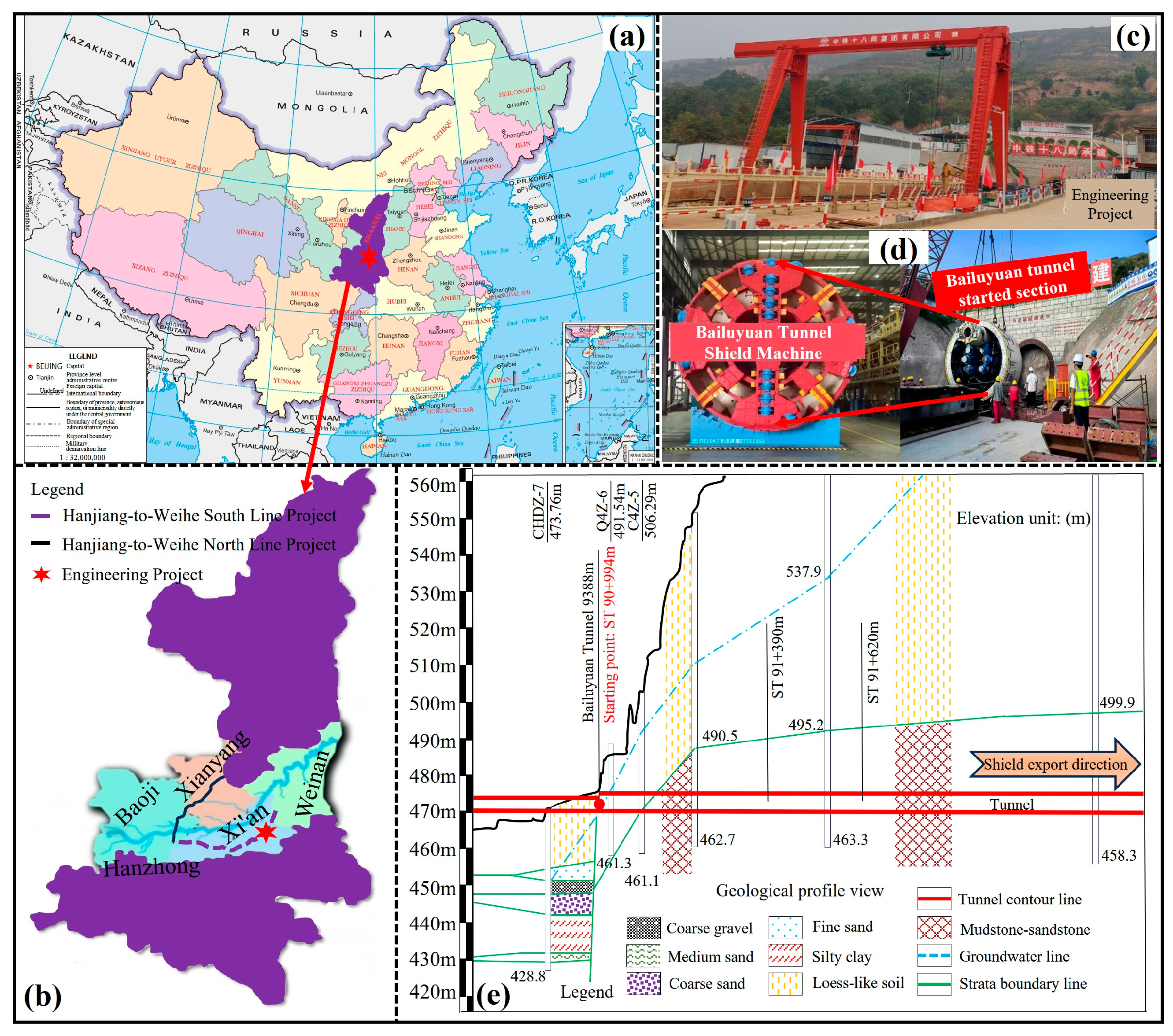
Studying the displacement response characteristics of the excavation face in shield tunnels can reveal the variation patterns of horizontal displacement under different factors, helping to identify the most critical influencing factors on tunnel stability, the secondary important ones, and those that may be insignificant, thereby facilitating the prevention of safety hazards at the source. Subsequently, risk assessment for deep-buried shield tunnels aims to reduce the probability of engineering accidents, primarily by adjusting construction measures in advance based on assessment results to avoid unnecessary casualties, property losses, and project delays. Therefore, this study focuses on the BaiLuYuan tunnel project within the ‘Hanjiang-to-Weihe River Water Diversion Project’ and employs the DEM to numerically simulate and analyze the shield tunneling process. The research aims to investigate how various tunneling parameters affect the stability of shield tunneling surface. Additionally, a model is developed to evaluate the risk of instability in the tunneling surface by considering tunneling parameters, geological conditions, design factors, and construction factors, followed by engineering validation and application. The resulting risk assessment model for shield tunnel instability plays a crucial role.
2. Discrete Element Analysis of Displacement Response Characteristics of Shield Tunnel Excavation Face Under Different Tunneling Parameters
2.1. Numerical Simulation Using the Three-Dimensional DEM
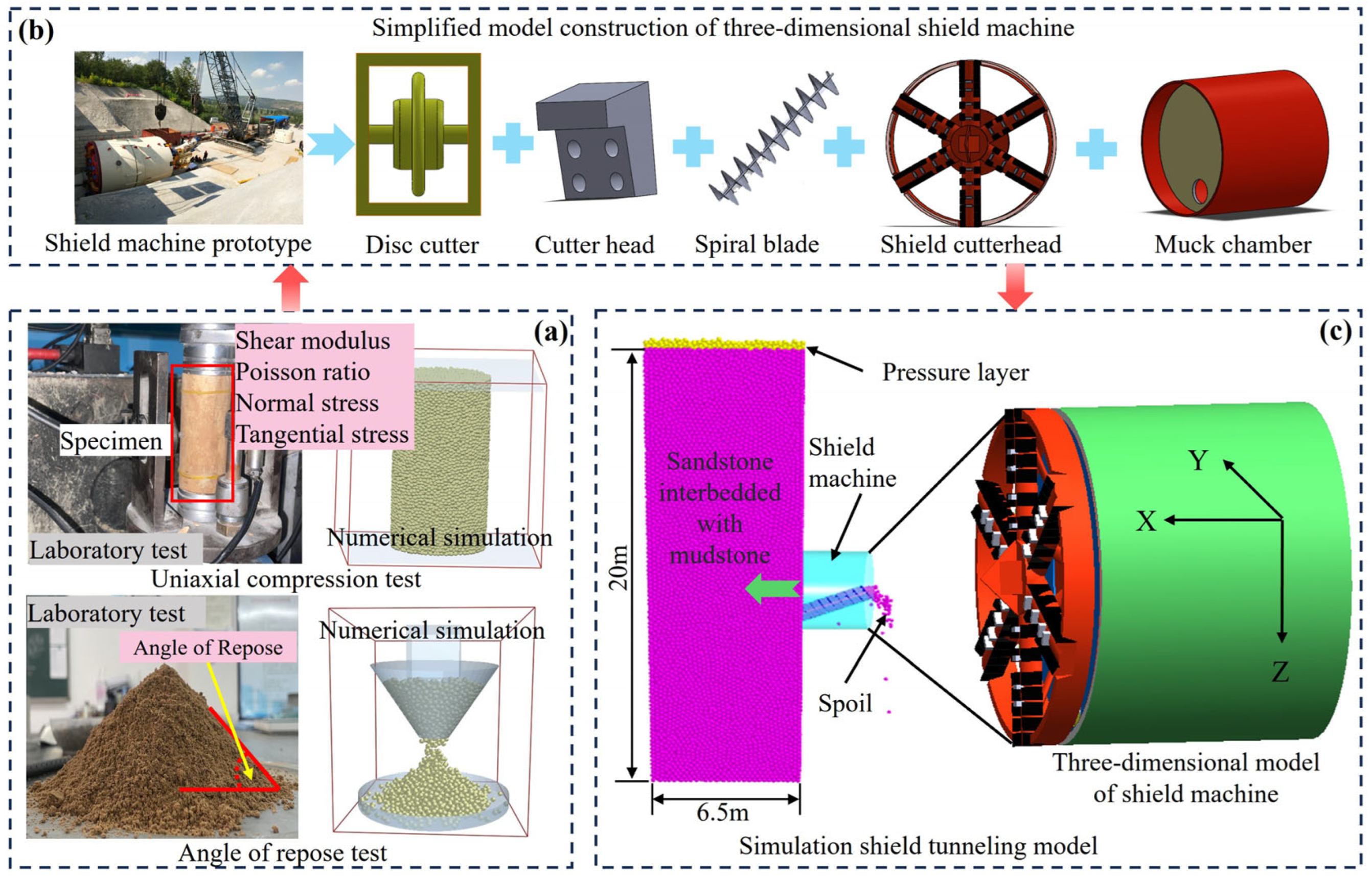
A three-dimensional numerical simulation of the shield tunneling process was conducted using the DEM. Firstly, in situ surrounding rock parameters were calibrated through uniaxial compression and repose angle tests, with all materials sourced from on-site sampling, specifically sandy mudstone and loess. Since the simulation requires interactions between particles and geometry, the properties of the particle materials—such as shear modulus, density, and Poisson’s ratio—were established, along with contact parameters like the static and rolling friction coefficients. The relevant mechanical index parameters include normal contact stiffness, tangential contact stiffness, critical normal stress, and critical tangential stress. When calibrating the DEM model, the verification index is the key factor to ensure the performance and accuracy of the model. Generally, the verification indexes of DEM model are density, friction coefficient, elastic modulus, stacking angle deviation, stacking density, porosity, and peak impact force. Through the evaluation and verification of the above indicators, the accuracy and reliability of the particle simulation are ensured.
Secondly, a simplified three-dimensional shield machine model was created using SolidWorks (v2021) software. The simplified model encompassed essential tunneling components, including the screw conveyor, shield body, soil chamber, and cutterhead [
42]. The cutterhead diameter was 5.1 m, the total machine length was 6.5 m, and the screw conveyor had an inclination angle of 36°.
Thirdly, when converting on-site conditions to DEM model dimensions, the Buckingham π theorem for dimensional scaling was first considered, and the calculated similarity ratio was 14. Then, a scaled ground model was constructed, in which soil particles were created to represent the strata. High in situ stress conditions typical of deep burial were simulated by generating dense particles above the soil layer. The X-axis was oriented along the tunnel axis, while the Z-axis was aligned with the direction of gravity. The longitudinal length of the model was 6.5 m, the shield tunneling layer height was 20 m, and the dense particle loading layer had a height of 0.5 m. The distance from the shield machine’s top to the model’s surface was 7.7 m. The Y-axis indicated the lateral direction, with the shield’s boundary positioned 7.95 m from both the left and right sides of the model. The distance from the shield machine’s lower edge to the model’s bottom boundary was 7.7 m. In the DEM, the contact model adopted was Hertz–Mindlin with JKR cohesion, with soil particle diameters ranging from 80 to 100 mm, and the grid size was set to 3R mm.
Finally, the shield machine model was imported into event driven execution manager EDEM (v2023) software, where its motion states were configured. Drawing from the geological features of the related project and the calibration outcomes, the parameters for the numerical model were established within the EDEM environment. The three-dimensional shield tunneling model enabled the numerical simulation of the earth pressure balance shield tunneling process.
Figure 1 illustrates the outcomes of the 3D DEM simulation. The model time step was set to 3.62 × 10
−6 s, with a total simulation time of 20 s. The model input parameters are as shown in
Table 1, the contact parameters as shown in
Table 2, and the relevant mechanical index parameters as shown in
Table 3. After selecting the time step, we conducted a specific verification using the Courant condition.
According to the above steps, the control variable method is used to study the influence of different tunnel buried depths, cutterhead opening rates, cutterhead rotation speeds, tunneling speeds, and chamber earth pressure ratios on displacement of excavation face.
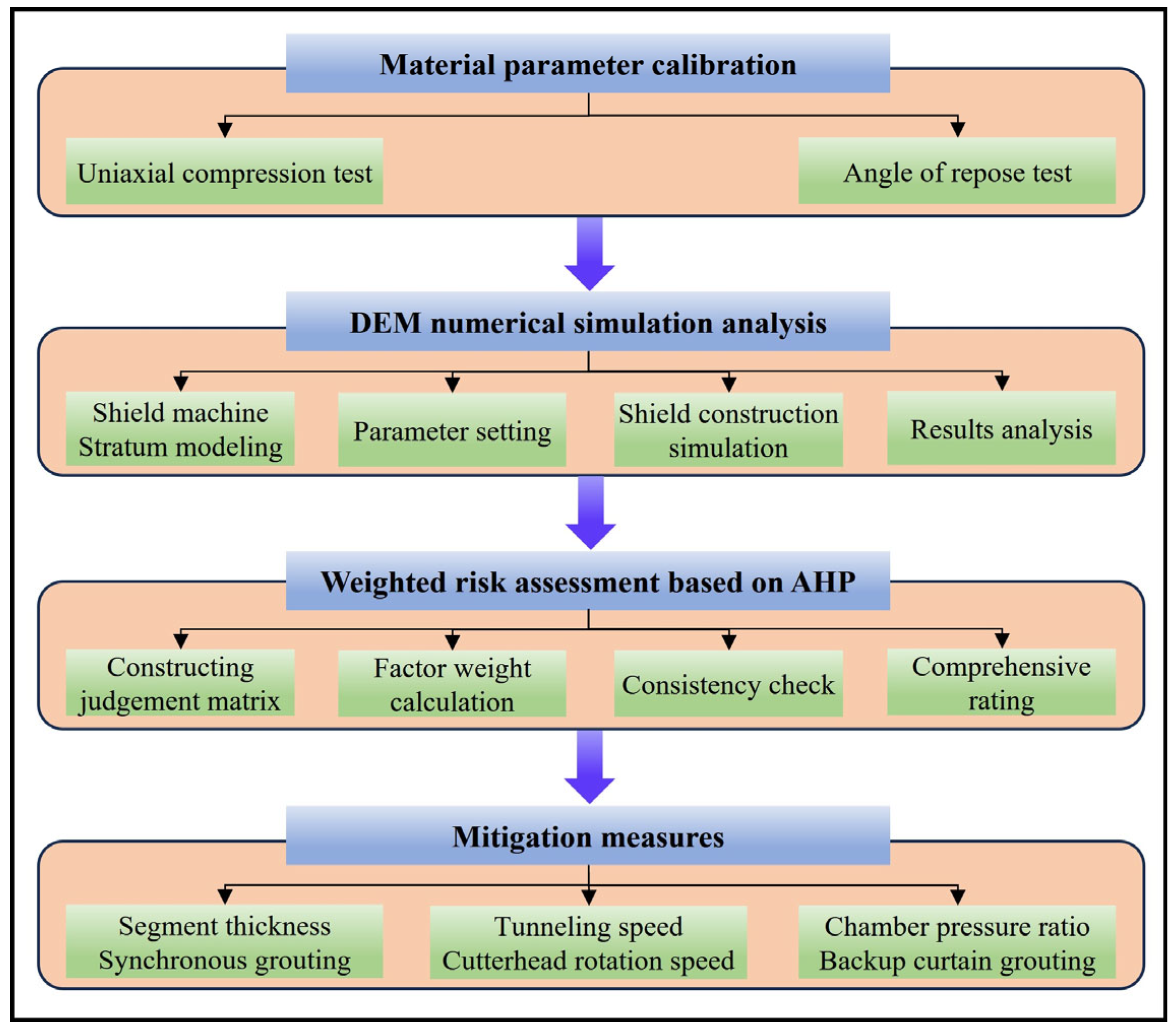
Following the aforementioned steps and using the control variable method, the influence patterns of various factors—such as different tunnel burial depths, cutterhead opening ratio, cutterhead rotation speed, advancement speed, and chamber earth pressure ratio (defined as the ratio of actual chamber earth pressure to excavation face soil pressure)—on excavation face displacement were investigated. The flow diagram of the modeling phase is depicted in
Figure 1.
2.2. Analysis of Displacement Response Characteristics of the Shield Tunnel Excavation Face
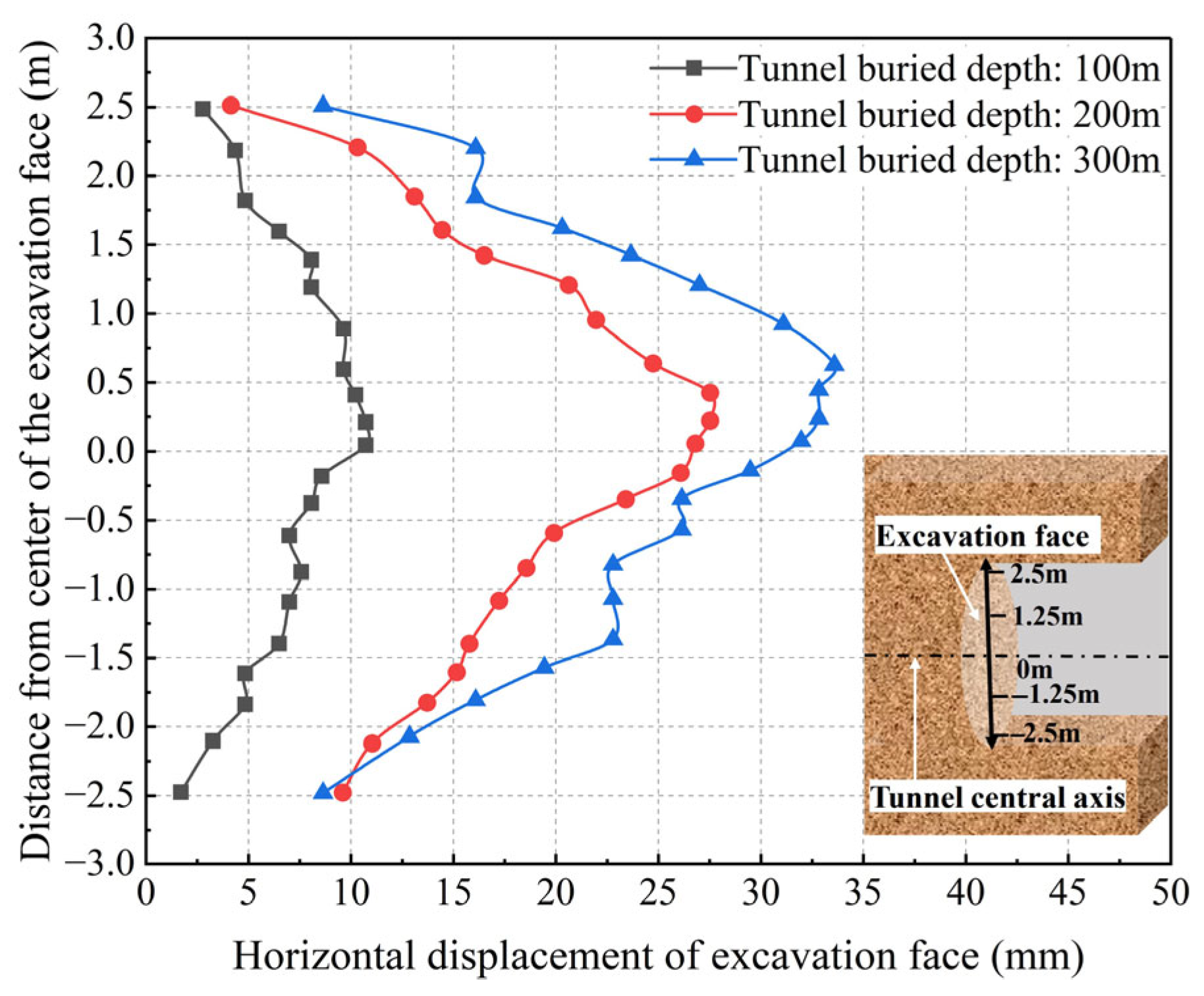
When the chamber earth pressure ratio is set to 1, the displacement response characteristics of the shield tunnel’s excavation face are analyzed for tunnel burial depths of 100 m, 200 m, and 300 m.
Figure 2 illustrates the variation curves of horizontal displacement for the excavation face at different tunnel burial depths [
3]. The horizontal displacement behavior of the excavation face is consistent across the three burial depths, indicating that the maximum displacement occurs at the center of the excavation face, with values gradually decreasing as the distance from the center increases. At burial depths of 100 m, 200 m, and 300 m, the maximum horizontal displacements of the excavation face are recorded as 10.7 mm, 27.6 mm, and 34 mm, respectively. This indicates that as the burial depth increases, the earth pressure on the tunnel excavation face rises, leading to a significant increase in the extrusion deformation of the excavation face, although the rate of increase becomes less pronounced.
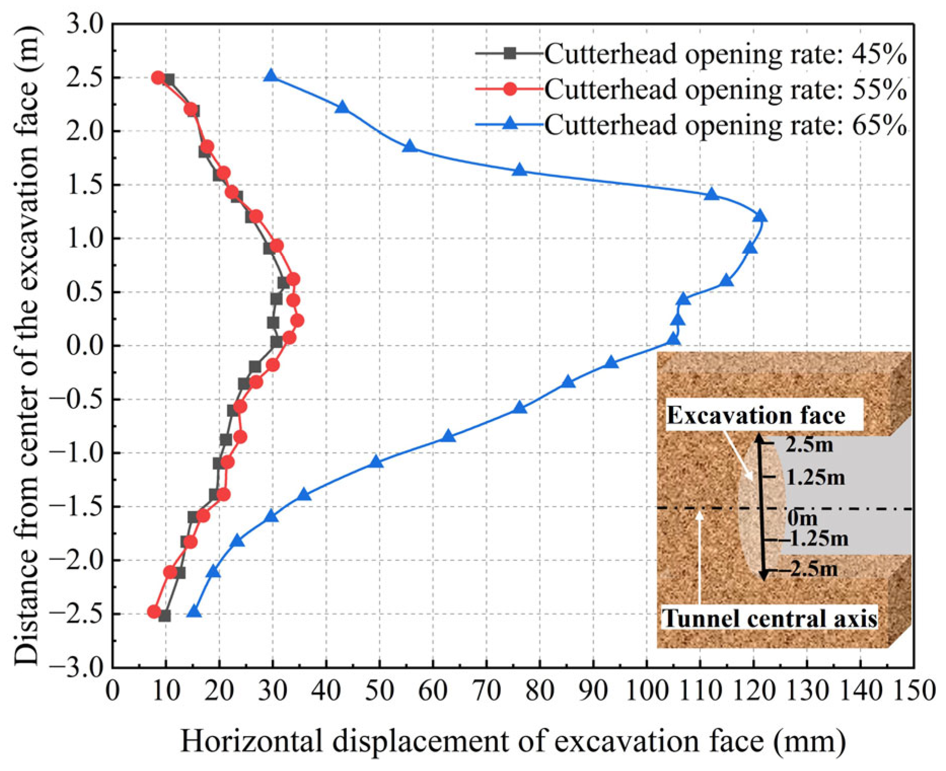
With other factors held constant, the impact of cutterhead opening rates of 45%, 55%, and 65% on the stability of the excavation face is evaluated.
Figure 3 illustrates the variation curves of horizontal displacement for the excavation surface under these different opening rates. The displacement patterns observed for the three different cutterhead opening rates are generally consistent, with all exhibiting significant displacements at the upper center of the excavation face and minimal displacements farther from the center. At a cutterhead opening rate of 45%, the maximum horizontal displacement recorded for the excavation face is 32.1 mm. At a cutterhead opening rate of 55%, the horizontal displacement of the excavation face shows only a slight increase compared to the previous rate. In contrast, when the opening rate reaches 65%, there is a marked increase in horizontal displacement, with a maximum value of 121.1 mm recorded. It shows that the reduction in the cutterhead opening rate will significantly increase the supporting effect on the front soil, which can effectively reduce the horizontal displacement of excavation face.
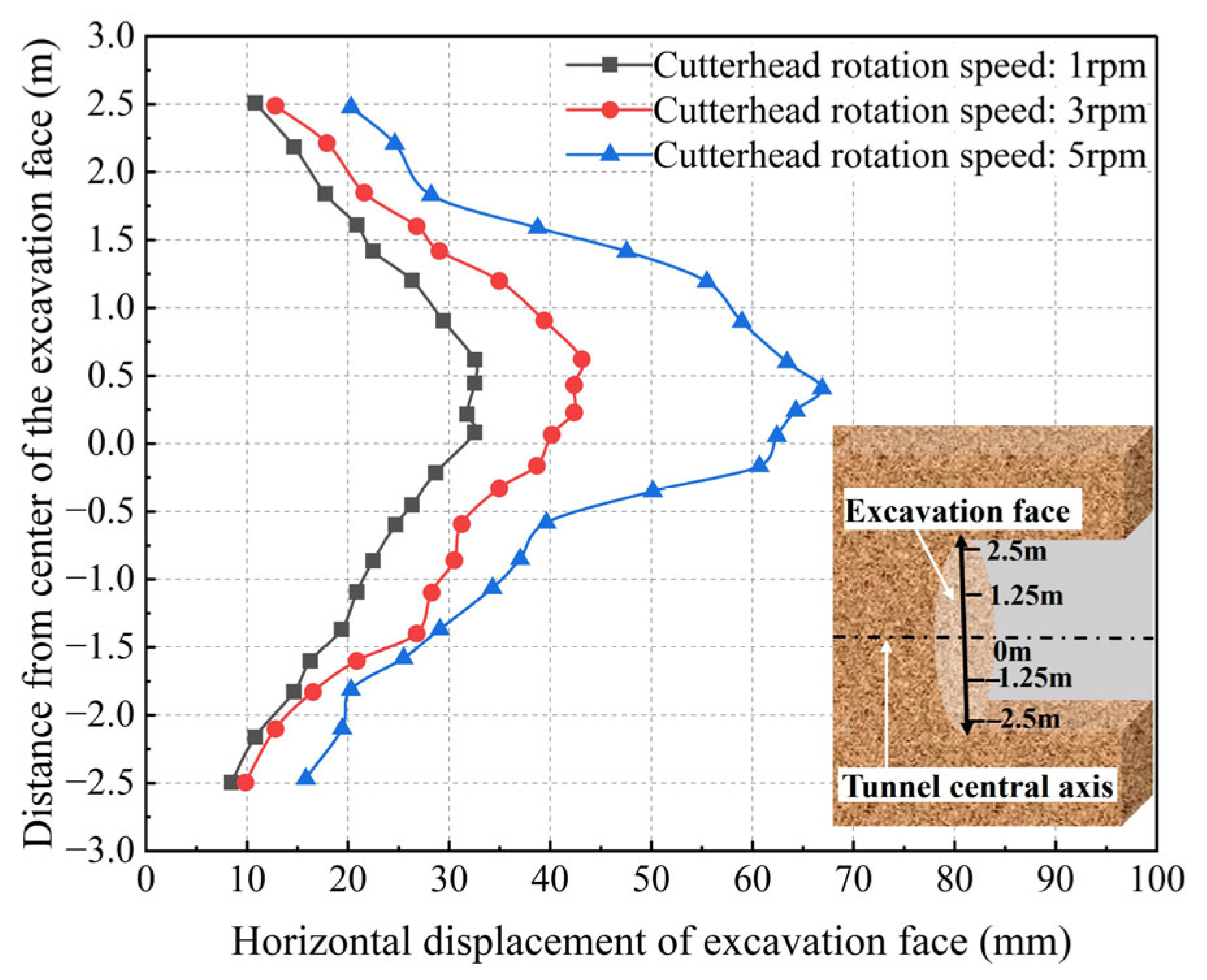
In this analysis, the impact of cutterhead rotation speed on the displacement of the excavation faces is examined while keeping other factors constant. The rotation speeds analyzed are 1 rpm, 3 rpm, and 5 rpm.
Figure 4 illustrates the change curves of the horizontal displacement of the excavation face at these different rotation speeds. At a rotation speed of 1 rpm, the maximum displacement of the excavation surface measures 32.5 mm. In contrast, at 5 rpm, this maximum displacement increases to 66.9 mm, indicating approximately a twofold increase. The intensity of disturbance caused by varying cutterhead rotation speeds affects the excavation surface differently. As the cutterhead rotation speed rises, the horizontal displacement of the excavation surface accelerates significantly, highlighting the substantial impact of cutterhead rotation speed on the surrounding soil of the excavation surface.
This analysis examines the effect of varying tunneling speeds on the stability of the excavation face, while keeping other factors constant. The tunneling speeds considered are 30 mm/min, 60 mm/min, and 90 mm/min.
Figure 5 presents the change curves for the horizontal displacement of the excavation face at these different speeds. The impact of varying tunneling speeds on excavation face stability is largely consistent: slower tunneling speeds result in less disturbance and reduced horizontal displacement of the excavation face. Conversely, as tunneling speeds increase, the horizontal displacement also rises, with the maximum displacement reaching 41.4 mm at the highest speed.
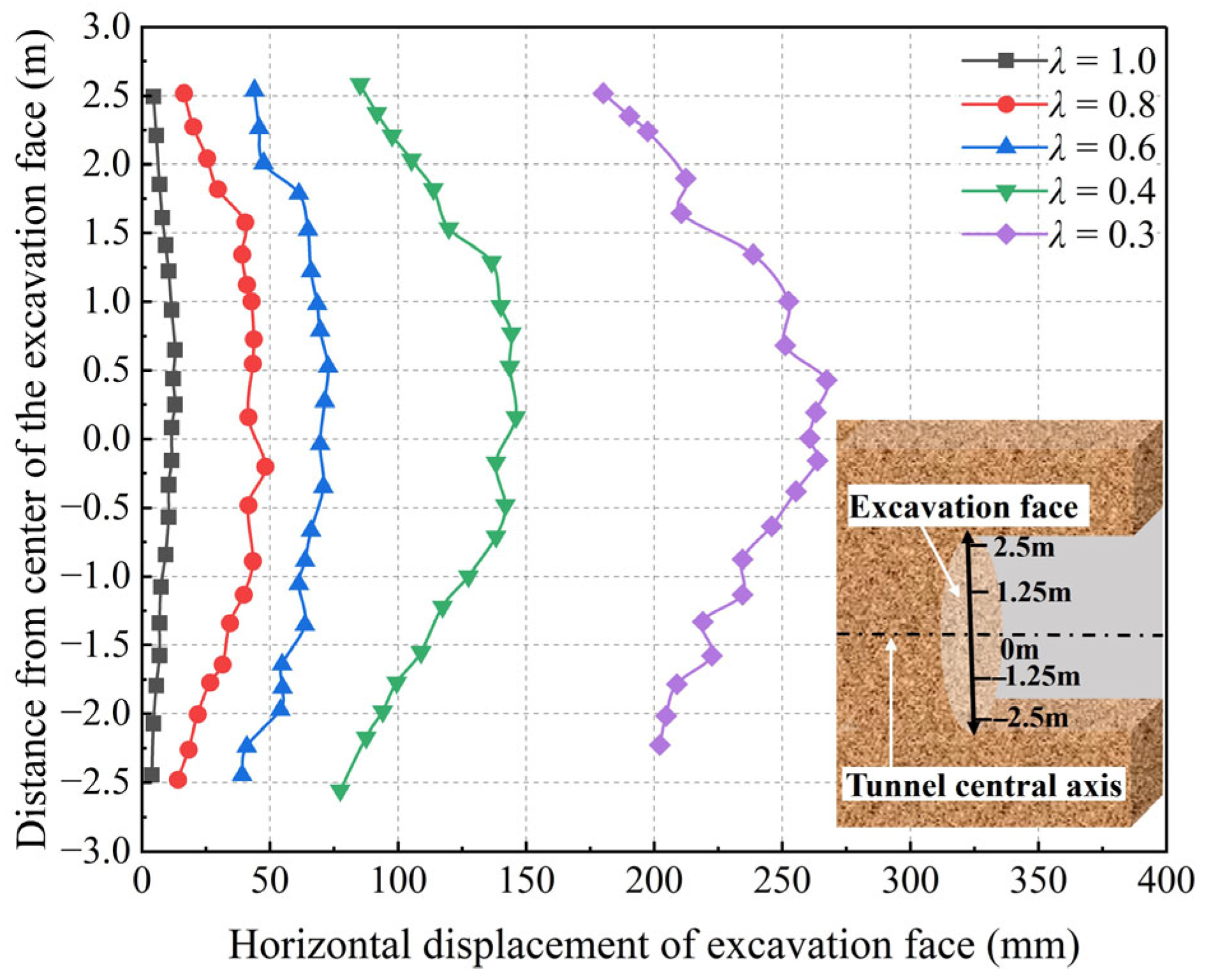
This analysis investigates the effect of the chamber earth pressure ratio (λ) on the stability of the excavation face, considering ratios of 1.0, 0.8, 0.6, 0.4, and 0.3 while keeping other factors constant.
Figure 6 illustrates the change curves for the horizontal displacement of the excavation face corresponding to these different pressure ratios. At a chamber earth pressure ratio of 1.0, the horizontal displacement of the excavation surface is measured at 12.9 mm. As the chamber earth pressure ratio decreases, the displacement increases markedly, indicating a decline in the stability of the excavation surface. When the chamber earth pressure ratio reaches a lower limit, the displacement of the excavation surface can soar to 267.3 mm. This demonstrates that variations in the chamber earth pressure ratio significantly affect the horizontal displacement of the excavation surface. Consequently, the chamber earth pressure ratio is crucial for maintaining the stability of the shield excavation face.
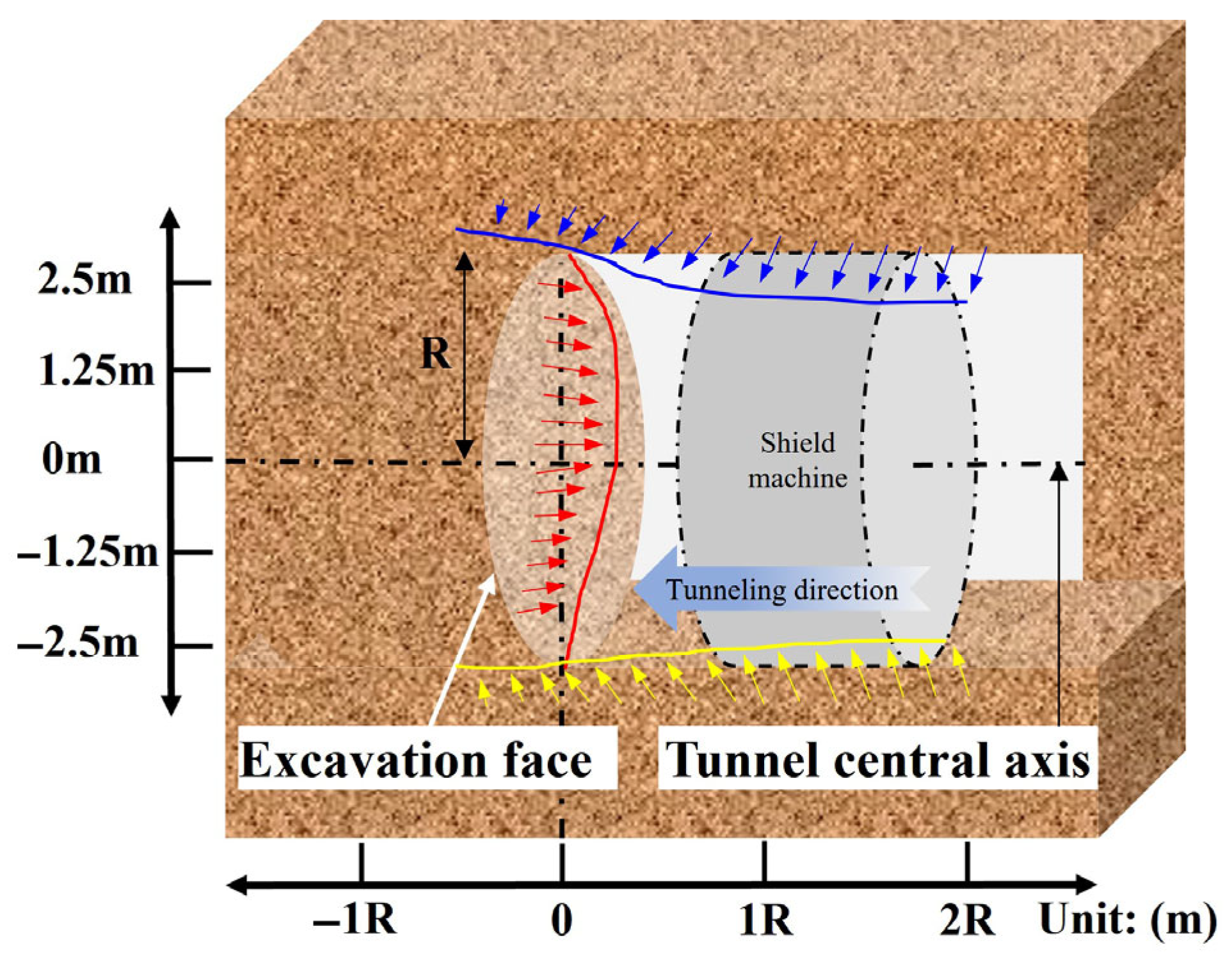
The failure modes of shield tunnels typically manifest as longitudinal cracks and localized bulging in the soil at the excavation face surface, and in severe cases, lead to a sudden increase in shield machine thrust resistance or even machine jamming. Subsidence cracks appear on the ground surface above the excavation face, while soil inside the tunnel collapses in a “quicksand-like” manner, accompanied by the inflow of water–sand mixtures into the tunnel. A schematic diagram of the deformation around the excavation face and surrounding area is shown in
Figure 7.
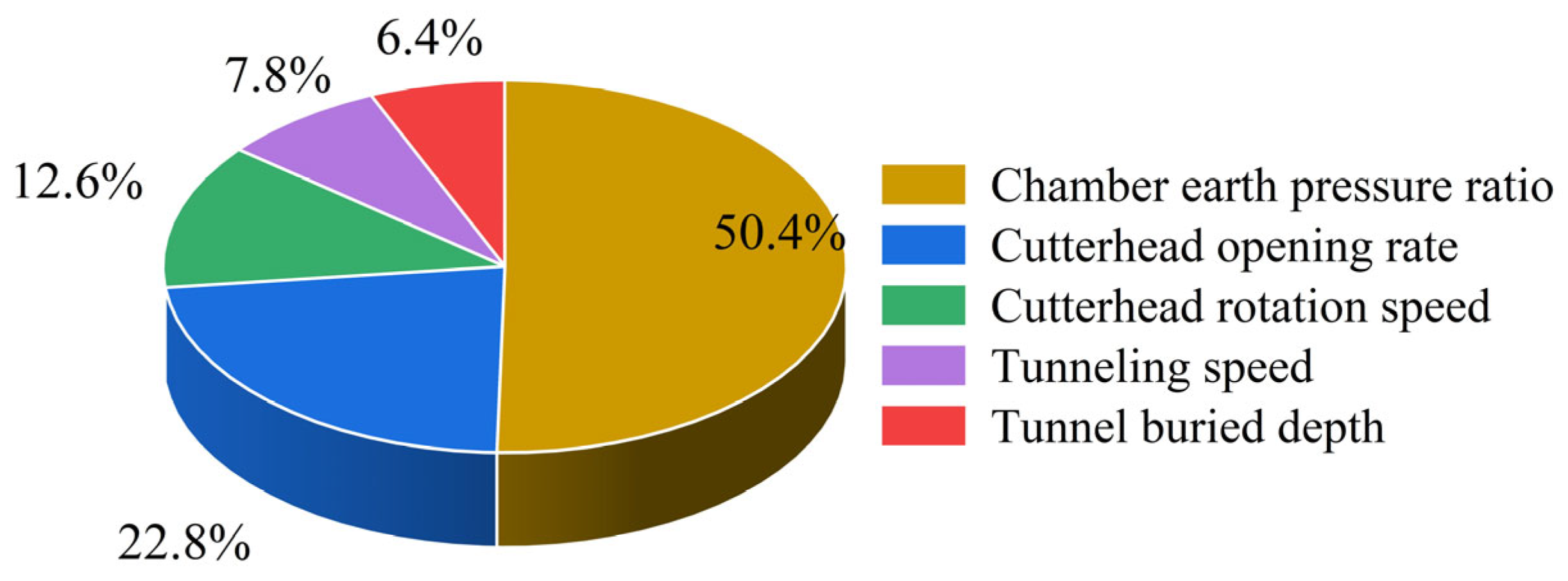
In summary, as parameters such as tunneling speed, cutterhead opening rate, tunnel burial depth, and cutterhead rotation speed increase, the horizontal displacement of the excavation face rises correspondingly. Conversely, a decrease in the chamber earth pressure ratio leads to a significant increase in the horizontal displacement of the excavation surface. λ < 0.5 triggers a sudden displacement spike. When the cutterhead opening ratio exceeds 55%, failure of the muck support system causes a sharp increase in horizontal displacement. At cutterhead rotation speeds above 3 rpm, the formation disturbance effect induces rapid growth of horizontal displacement. When the advance rate surpasses 30 mm/min, delayed support response results in uniform augmentation of horizontal displacement. For tunnel burial depths exceeding 200 m, the amplification effect of high geostress and water pressure leads to gradual enlargement of horizontal displacement. The proportional contributions of different parameters to displacement are illustrated in
Figure 8, while
Table 4 ranks the influence degrees of various factors.
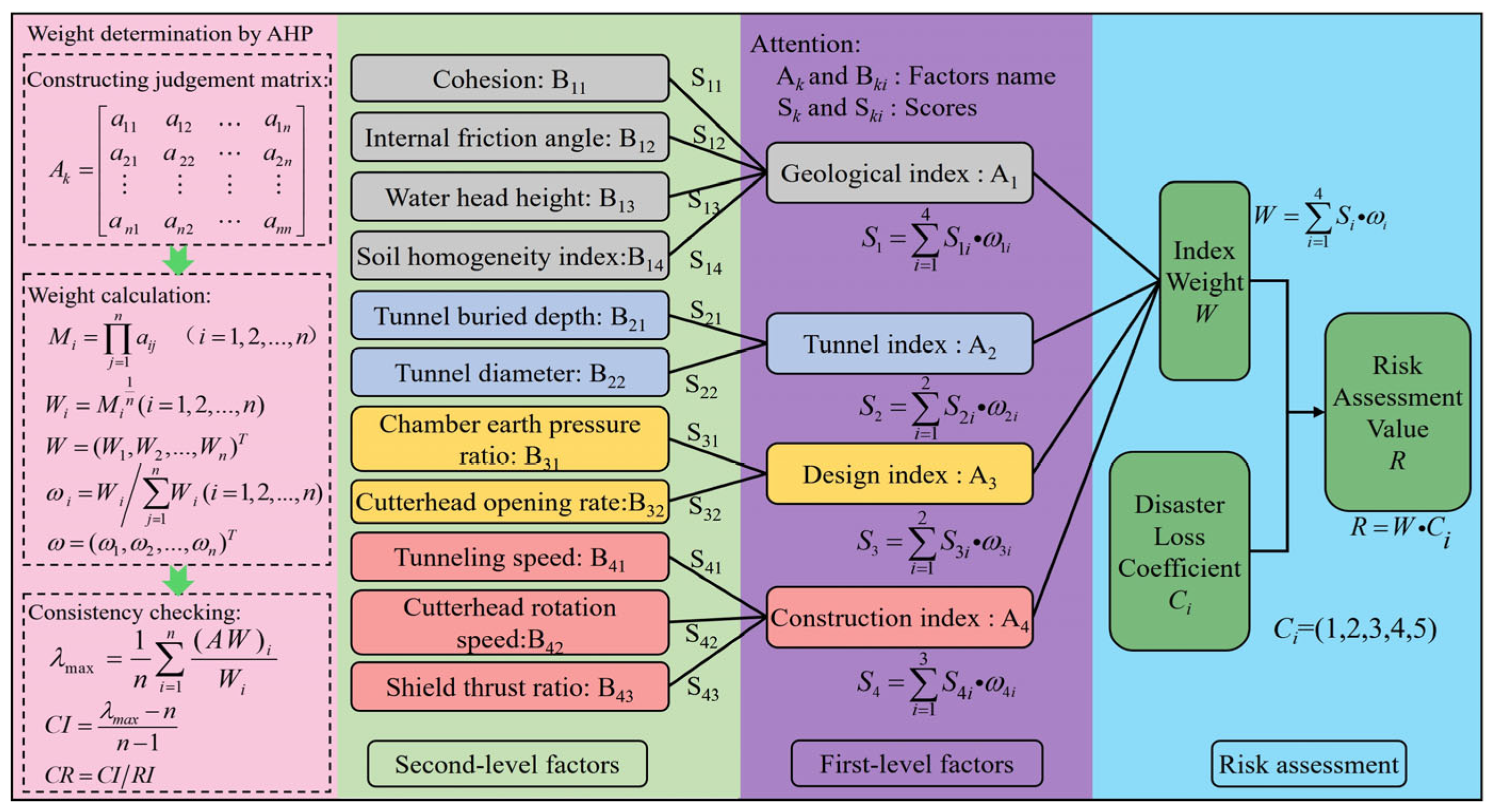
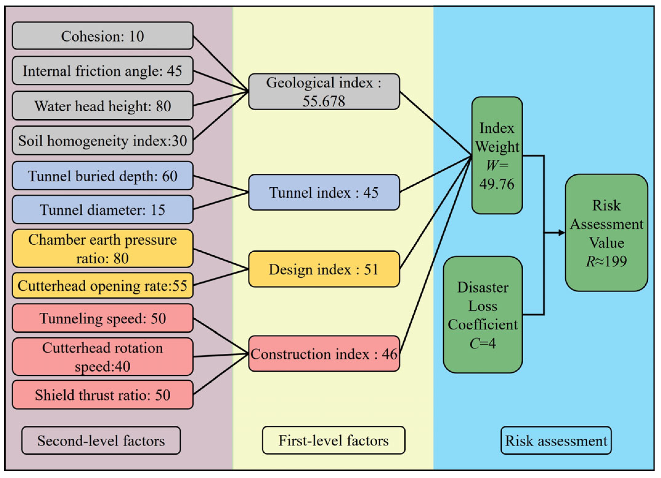
The tunnel burial depth, cutterhead opening rate, cutterhead rotation speed, tunneling speed, and chamber earth pressure ratio are all critical factors affecting the stability of the shield tunnel excavation face. Current risk assessment models for shield tunnel excavation face stability tend to place greater emphasis on geological conditions and shallow tunnel scenarios, while underestimating the impact of excavation parameters. This oversight presents certain limitations. To address these issues, this study proposes a weighted index risk assessment method that holistically considers geological, design, tunnel, and construction factors, thereby enhancing the accuracy of risk evaluations.
5. Discussion
Given that tunnel collapse poses significant risks to lives and economic stability, this study employed discrete element modeling to investigate horizontal displacement responses at excavation faces under key influencing factors. The revealed displacement patterns informed an (AHP)-based risk assessment for the target project, enabling optimized construction protocols to enhance both safety and cost-efficiency in shield tunneling.
5.1. Comparative Analysis of Findings
While horizontal displacement patterns at the excavation face align with tunnel mechanics theory, parameter variations across different factors induce distinct displacement relationships. For example, increasing advancement speed yields relatively stable trends. Higher cutterhead opening ratios trigger sharp displacement increases. This divergence likely results from multi-factor coupling effects in complex geotechnical environments.
Our analysis identifies the chamber earth pressure ratio as the dominant influence, followed by cutterhead rotation speed, opening ratio, and advancement speed. This prioritization diverges from shallow-tunnel studies that emphasize construction factors (for example, grouting support) for face stability. It should be noted that such discrepancy is reconcilable: collapse mechanisms (for example, tunnel face failure) fundamentally involve energy-driven non-equilibrium evolution of rock masses, encompassing kinetic–potential energy conversion and frictional dissipation. In deep tunnels, elevated in situ stress and groundwater levels endow surrounding rock with substantial inherent energy, making intrinsic rock stability critical. Conversely, shallow-tunnel safety primarily relies on external support measures.
5.2. Factor Significance and Methodological Constraints
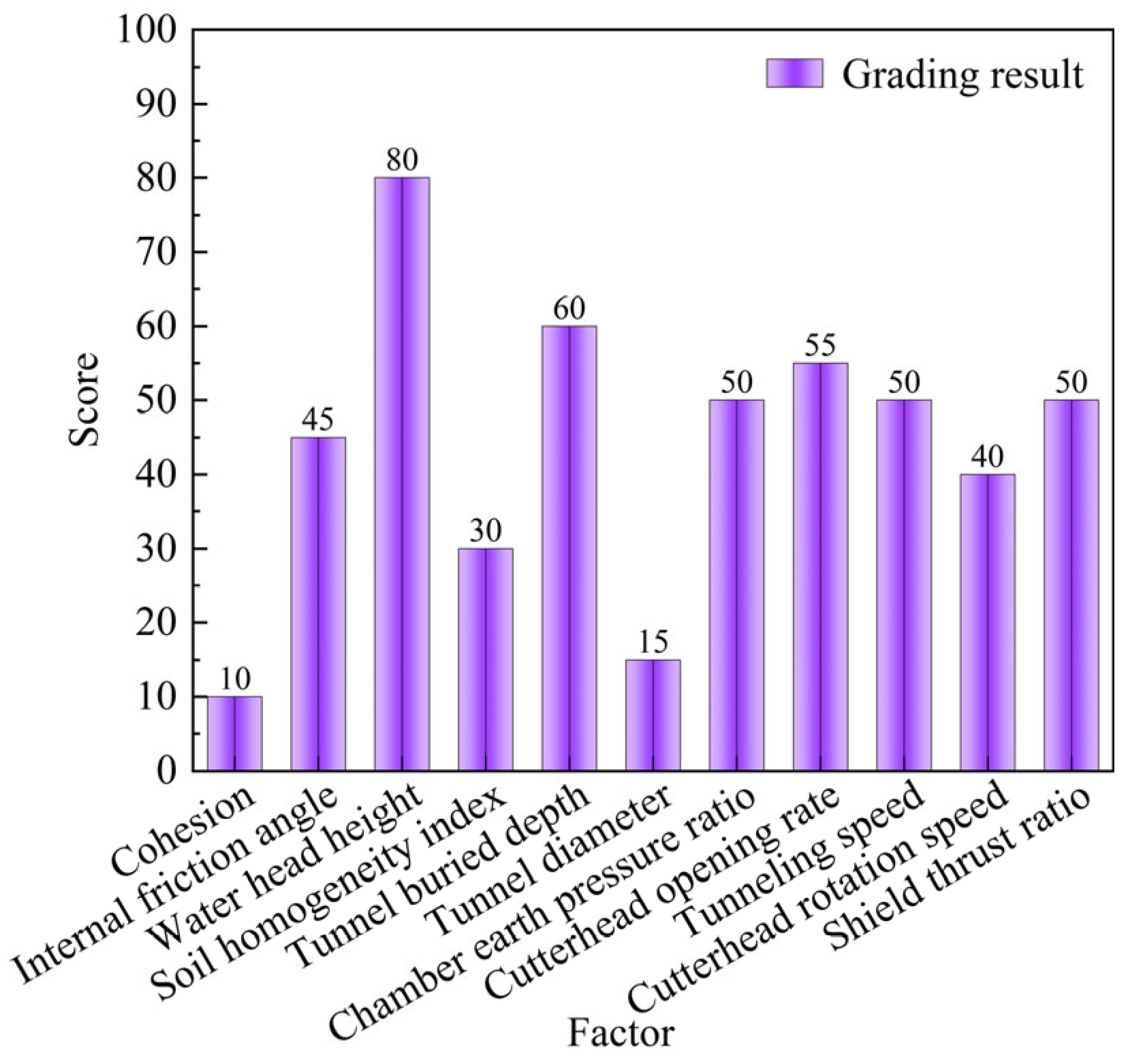
This study specifically analyzes factors including tunnel buried depth, cutterhead opening ratio, cutterhead rotation speed, advancement speed, and chamber earth pressure ratio. Combining the AHP method, weight calculations were conducted on 11 factors. As seen in
Figure 5, the shield chamber earth pressure ratio is the most critical factor; chamber earth pressure directly affects the balance between excavation face support force and surface settlement, and its dynamic fluctuations can trigger chain instability risks. Following these, advancement speed, cutterhead rotation speed, and cutterhead opening rate hold secondary importance. Since these factors exhibit mutual synergistic effects, their significance differences are minor. Conversely, the tunnel buried depth factor has relatively low weight compared to the former. This is because tunnel buried depth undergoes rigorous investigation and design to finalize the construction scheme; thus, for tunnel buried depth alone, the probability of causing collapse accidents is small. Additionally, based on actual cases of excavation face collapse accidents during shield construction in recent years in Guangzhou, Nanjing, Foshan, and other locations, the majority are caused by improper control of chamber earth pressure balance. This indirectly reflects the reliability of our results.
The limitations of the numerical simulation method in this study are as follows: The finite element method has inherent defects in simulating granular materials, contact interactions, and collapse mechanisms. If used alone, it cannot fully meet the demands of engineering simulation. The limitations in collecting and organizing monitoring data during on-site construction are as follows: In the tunnel construction process, most monitoring points typically have monitoring devices deployed after excavation completion. This results in the inability to collect data promptly during excavation. In the AHP method, different experts may be influenced by personal subjectivity when scoring factors. A comparison between past models and the current research is shown in
Table 12.
5.3. Future Research and Challenges
Although we have conducted risk prediction, numerous risks persist during actual construction. In addition to disturbances caused by construction to surrounding rock, on-site environmental conditions may also trigger engineering accidents. In deep-buried environments, the elastic strain energy stored in surrounding rock is released during excavation, potentially leading to sudden rockbursts that cause brittle failure of surrounding rock. Water pressure not only increases the loading on support structures but can also induce water inrush and sand gushing accidents under seepage forces. This necessitates identifying geological structures through advanced geological prediction and combining with solutions such as grouting for water sealing or high-pressure waterproof curtains. Therefore, future research could broaden risk factors and investigate the coupling of finite element and discrete element methods in numerical simulations while considering the impacts of different environments. This will enhance the reliability and universal applicability of engineering models. Future studies could also explore the integration of methods like fuzzy AHP and machine learning techniques, which may improve the accuracy and applicability of tunnel risk assessment.
The methodology in this study provides technical support for enhancing the intelligence level and decision-making efficiency of TBM construction, demonstrating potential for integration into existing industrial systems. The excavation face stability obtained through risk assessment can directly serve as key input data for the decision support module of TBM intelligent decision systems. By connecting the output of this study to decision systems in real-time via API interfaces or middleware, operators or automated decision modules can receive more precise and timely condition assessments and operational suggestions (for example, adjusting thrust force, cutterhead rotation speed, advancement speed, support grouting, etc.), thereby facilitating superior excavation efficiency and safety control. This approach can be designed as a relatively independent software module that easily embeds into existing TBM-integrated decision platforms through clearly defined input and output interfaces. Such integration can significantly improve the “perception–analysis–decision–execution” closed-loop capability of TBM construction, promoting tunnel engineering toward smarter, reduced-manning, efficient, and safer development.
In conclusion, this research provides foundational theoretical support for assessing excavation face stability in deep-buried shield tunnels, particularly regarding deformation patterns of horizontal displacement under different parameters and the optimization of mitigation measures during shield construction.
6. Conclusions
Through the risk assessment in advance, we can help prevent the occurrence of collapse accidents in the process of shield construction. Based on practical engineering, the three-dimensional DEM is used to study the displacement response characteristics of the excavation face position of the shield tunnel under different factors. The risk assessment index system integrating geological index, tunnel index, design index, and construction index is constructed, and the weighted index method is proposed. The risk assessment method has been applied and validated in evaluating the risk of excavation face instability in the Bailuyuan tunnel, leading to the following conclusions.
The tunnel buried depth, cutterhead opening rate, tunneling speed, cutterhead rotation speed, and chamber earth pressure ratio each exert varying degrees of influence on the deformation of the shield tunnel’s excavation surface. As the cutterhead opening rate rises, the displacement of the excavation surface initially increases gradually before accelerating significantly. In contrast, a reduction in the chamber earth pressure ratio results in a sharp increase in horizontal displacement. When considering the extent of their impact, the chamber earth pressure ratio has the most substantial effect on excavation face displacement, while the tunnel’s buried depth is the least influential factor. The weight proportion is approximately 42.8%, while the tunnel burial depth demonstrates limited impact on the horizontal displacement of the excavation face.
A risk assessment index system considering geological index, tunnel index, design index, and construction index is constructed, in which various factors are independently affected. A weighted index risk assessment method is introduced, which utilizes the AHP to establish the weight of each risk source. Subsequently, the identified risk factors are evaluated and assigned appropriate weights. Finally, the risk assessment value is obtained by using the risk loss coefficient. This method has the characteristics of comprehensive risk factors and a simple calculation process. The reliability and validity of the proposed method were confirmed through its application in practical engineering scenarios.
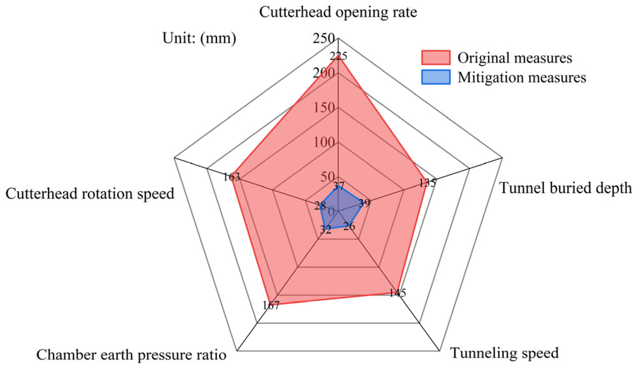
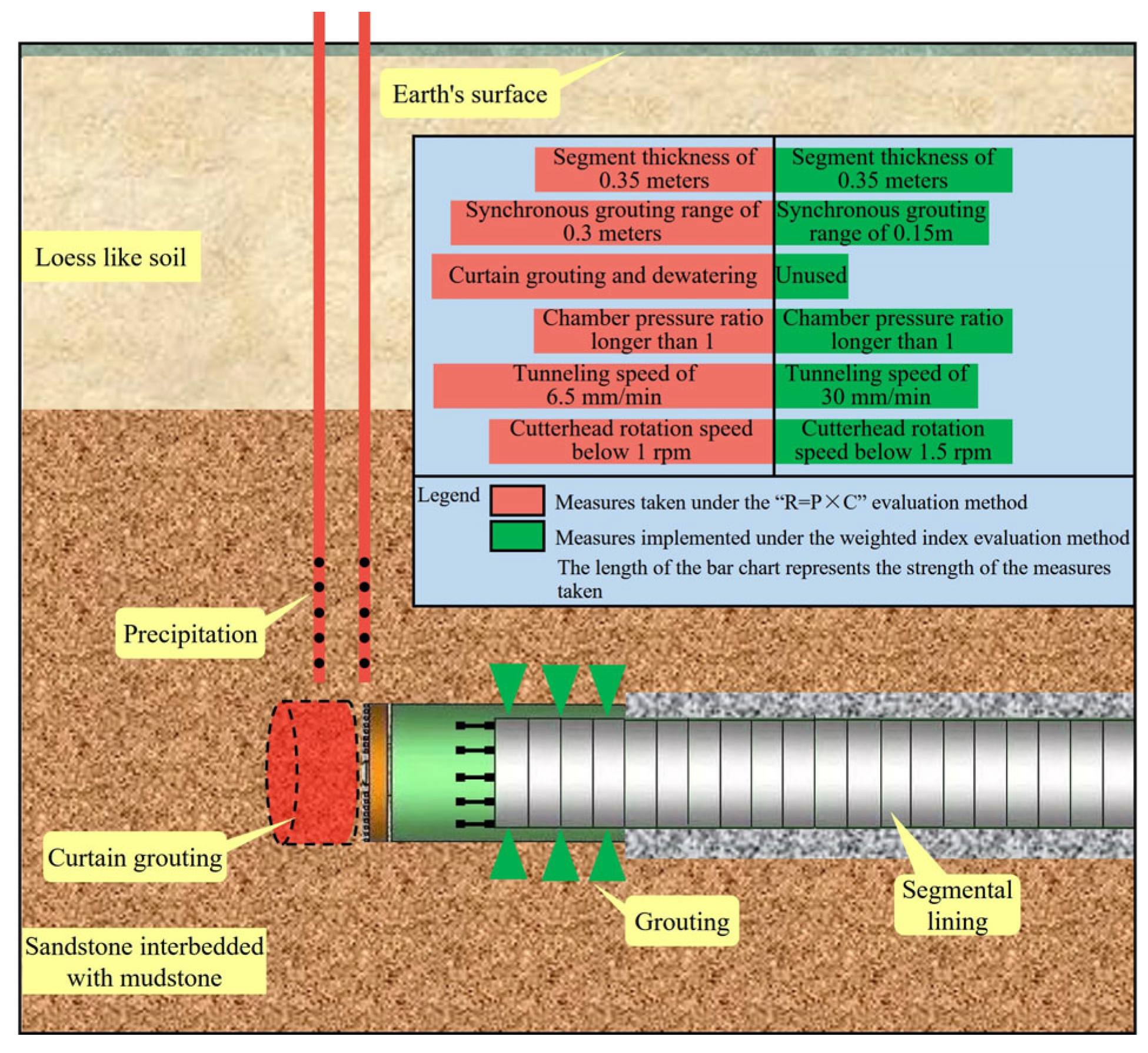
During normal shield tunneling operations, the soil chamber earth pressure ratio constitutes the most critical influencing factor. Additionally, advancement speed, cutterhead rotation speed, and hydraulic head height represent primary risk factors for excavation face instability. The reinforcement measures under the evaluation results of the weighted index method (risk level: Grade II), the soil pressure ratio is greater than 1, the shield tunneling speed does not exceed 30 mm/min, the cutterhead rotation speed does not exceed 1.5 rpm, and the grouting range is 0.15 m. Finally, combined with the on-site implementation, it is shown that the shield machine successfully passed the risk assessment section without any accidents.
The limitation of this study is that the simplified linear weighting method and model are only applied in a single project. The linear weighting assumption assumes that the contribution of each influencing factor to the instability of the excavation face is independent and linearly superimposed, but in actual geotechnical engineering, there is a significant nonlinear coupling effect between multiple factors. Secondly, the geological conditions and engineering parameters of the project are specific, and the model parameters are based on the project, which may lead to insufficient adaptability to different geological types. In future studies, the applicability of the model can be tested under other geological conditions (for example, water-rich sand stratum, composite stratum), and the working conditions can be analyzed and the model can be improved. It may also be integrated into the real-time tunnel control system to improve the practicability of the model. In addition, the research on tunnel safety risk assessment based on artificial intelligence algorithms can be carried out, and the theoretical depth of the model can be further improved on the basis of multi-scenario verification and engineering application.
