Article

Finite Element Modeling and Performance Evaluation of a Novel 3D Isolation Bearing

1
CCCC First Highway Northwest Engineering Co., Ltd., Xi’an 710075, China
2
School of Civil Engineering and Architecture, Hainan University, Haikou 570228, China
3
School of Civil Engineering, Chang’an University, Xi’an 710061, China
*
Author to whom correspondence should be addressed.
Buildings 2025, 15(14), 2553; https://doi.org/10.3390/buildings15142553
Submission received: 24 June 2025 / Revised: 16 July 2025 / Accepted: 17 July 2025 / Published: 19 July 2025
(This article belongs to the Special Issue Seismic Analysis and Design of Building Structures)

Abstract

A numerical investigation is conducted to examine the mechanical properties of a novel three-dimensional (3D) isolation bearing. This device is primarily composed of a lead rubber bearing (LRB), disc springs, and U-shaped dampers. A finite element model is developed and validated against the previous experimental results. Subsequently, comprehensive analyses are performed to evaluate the influence of vertical loadings, shear strains, and the number of U-shaped dampers on the horizontal behavior, as well as the effects of displacement amplitudes and the number of dampers on the vertical performance. Under horizontal loading conditions, the bearing demonstrates reliable energy dissipation capabilities. However, the small lead core design limits its energy dissipation capacity. Compared with the bearing without U-shaped dampers, the bearing’s energy dissipation capacity increases by 628%, 1300%, and 2581% when employing 1, 2, and 4 dampers on each side, respectively. Regarding vertical performance, the innovative disc spring group design effectively reduces the tensile displacement of the LRB under tension, thereby enhancing the overall tensile capacity of the bearing. Furthermore, in comparison to their contribution to horizontal energy dissipation, the U-shaped dampers play a relatively minor role in vertical energy dissipation.

1. Introduction

Currently, various horizontal seismic isolation technologies have reached a relatively mature stage and are widely applied in engineering structures [1]. However, due to the multi-dimensional characteristics of earthquake ground motions, the vertical responses of the structures, including long-span structures, cantilever structures, and high-rise buildings, might be much higher than the horizontal responses, especially when these structures are located at the epicenter of earthquakes or near fault zones [2,3]. To ensure the safety of structures, the research and innovation of three-dimensional (3D) isolation technologies and related devices are still desperately needed.
The prototype of 3D isolation technologies can be traced back to the 1970s, when Seigenthaler [4] used thick natural rubber blocks as isolation bearings in post-disaster reconstruction. Over the past half century and more, 3D isolation technologies and devices have made great progress, and some have been applied in practice. To isolate both horizontal and vertical ground motions, the existing 3D isolation bearings can be classified into two categories from the perspective of structural configurations: independent-type and combined-type. The independent 3D isolation bearings couple horizontal and vertical responses into single components, such as thick rubber bearings (TRBs) [5,6], helical springs [7], and air springs [8]. Although the construction of such bearings is relatively simple, their analysis and design is complicated due to the mutual influence of horizontal and vertical mechanical properties [9]. At present, this type of bearing, especially thick rubber bearings, is mainly applied in nuclear power facilities [10]. The combined 3D bearings can be decomposed into horizontal isolation devices and vertical isolation devices, which are used to isolate horizontal and vertical motions, respectively. In this way, scholars have creatively developed a variety of 3D isolation bearings.
By integrating a horizontal rubber bearing and disc springs in series, Fujita and Kato [11], Xiong [12], and Zhao et al. [13] previously conducted 3D isolation bearing tests. To further improve the tension-resistant capacity and overturn resistance of 3D bearings, wire rope [14], an anti-extraction device [15], a steel plate damper [16], and SMA strands [17] were also added to this type of bearing. Kashiwazaki et al. [18] and Mo et al. [9,19] proposed a 3D isolation bearing composed of rubber bearing and air spring and completed a shaking table test. Liu et al. [20] and Xu et al. [21] proposed a 3D isolation device by connecting several inclined laminated lead rubber bearings (LRBs) in series with a horizontal LRB and completed a series of static tests and a shaking table test. By connecting a horizontal LRB with multiple hydraulic cylinders in series, Chen et al. [22] developed a new 3D isolation device. Similarly, Liang et al. [23] developed a new 3D isolation bearing by connecting a horizontal LRB with a vertical ring spring bearing (RSB) arranged vertically in series. Based on multiple inclined LRBs, Wei et al. [24] developed an inclined sliding 3D seismic isolation device in which sliders and limiters are also included. The finite element simulation results show that the device has stable hysteretic performance and good energy dissipation capacity. Based on a laminated natural rubber bearing improved with a pre-compressed disc spring, Luo et al. [25] proposed a 3D isolation bearing by adding spring bearings in series. Scholars [26,27] also sought to develop new 3D isolation bearings, which are made of LRBs and TRBs in series. The standard LRBs isolate the horizontal component of earthquakes, and the TRBs can be used for vertical isolation.
Based on friction pendulum bearings, Han et al. [28] developed a 3D isolation device, using a friction pendulum system to isolate horizontal motions and an air spring to isolate vertical motions, respectively. Cao et al. [29] developed a 3D isolation bearing with disc springs as the vertical vibration isolation component and a single friction pendulum as the horizontal vibration isolation component. The bearing not only achieved vertical isolation of building structures under environmental excitation but horizontal isolation under seismic excitation. Cao et al. [30] also presented a 3D isolation bearing to mitigate the horizontal seismic action caused by earthquakes and the vertical vibration generated by train operation. The 3D bearing consists of two modules: one is a thick-layer rubber bearing for vertical vibration isolation and the other is a friction pendulum for horizontal vibration isolation. Kitayama et al. [31] proposed a 3D isolation system which is composed of triple friction pendulum isolators acting as a horizontal isolation module and a coil spring-damper system acting as a vertical isolation module. They further conducted a series of probabilistic seismic analyses for non-isolated, horizontally isolated, and 3D-isolated electrical transformers. Connecting a quasi-zero stiffness system with a horizontal friction pendulum, Zhou et al. [32] developed a 3D bearing and applied it to a high-rise building model.
Other combined-type 3D isolation bearings have also been proposed in recent studies. For instance, to address the insufficient energy dissipation capacity and to reduce the horizontal constraint imposed by disc springs, Yu et al. [33] developed a 3D isolation device consisting primarily of disc springs, U-shaped dampers, and a friction pendulum system. Furthermore, Yu et al. [34] presented a 3D isolator capable of achieving self-centering behavior under horizontal loadings and exhibiting quasi-zero stiffness under vertical loadings. The self-centering capability is provided by shape memory alloy U-shaped dampers (SMA-UDs), and the quasi-zero stiffness (QZS) property is realized by the negative stiffness of a disc spring (DS) isolator and the positive stiffness of SMA-UDs. To enhance vertical seismic isolation performance and improve the seismic resilience of isolation bearings, Sha et al. [35] proposed a 3D isolation bearing integrating a disc-spring system (DSS), a high-damping rubber bearing (HDR), and a horizontal spring system (HSS). In this design, the DSS is engineered with low vertical stiffness to optimize vertical isolation, whereas the HSS contributes a self-centering force that enhances the seismic resilience of the HDR. This study presents a comprehensive theoretical analysis of both horizontal and vertical stiffness components. The vertical performance of the 3D isolation bearing is primarily attributed to the DSS, while the horizontal performance arises from the combined contributions of the HSS and HDR.
Among existing 3D isolation bearings, the primary horizontal isolation devices are LRBs and friction pendulum bearings, which are widely adopted due to their mature technology and ease of manufacture. The vertical isolation devices mainly consist of disc springs, air springs, ring springs, and helical springs. To further enhance the performance of these systems, the integration of additional functional components has become increasingly common. However, from a practical application perspective, the manufacturing complexity and cost of 3D isolation bearings are critical factors that must be carefully considered.
Inspired by the advantages of LRBs and disc springs, this paper proposes a novel 3D isolation bearing comprising an LRB serving as the horizontal isolation module and two groups of disc springs acting as the vertical isolation module. Additionally, U-shaped steel dampers are incorporated to improve the energy dissipation and safety of the bearing. Compared to existing 3D isolation bearings, the proposed design offers several notable features: (1) The vertical disc springs are divided into two groups: one for compression and the other for tension, which enhances the stability of the disc springs and facilitates independent control of the compression and tension stiffness; (2) The inclusion of U-shaped dampers allows for a reduction in the lead core diameter of the bearing while simultaneously enhancing its energy dissipation capacity; (3) The incorporation of wire ropes serves as a displacement-limiting mechanism, thereby improving the overall safety of the bearing at extreme displacements.
To evaluate the mechanical performance of the proposed bearing, a numerical investigation is conducted based on previous experimental data. First, finite element models are established and validated using the prior horizontal test results by the authors. Subsequently, a detailed parametric analysis is carried out to examine the horizontal and vertical mechanical behaviors of the bearing under various conditions, considering key parameters such as the vertical load magnitude, the shear or vertical displacement levels, and the number of U-shaped dampers employed.

2. Configuration and Working Mechanism of Bearing
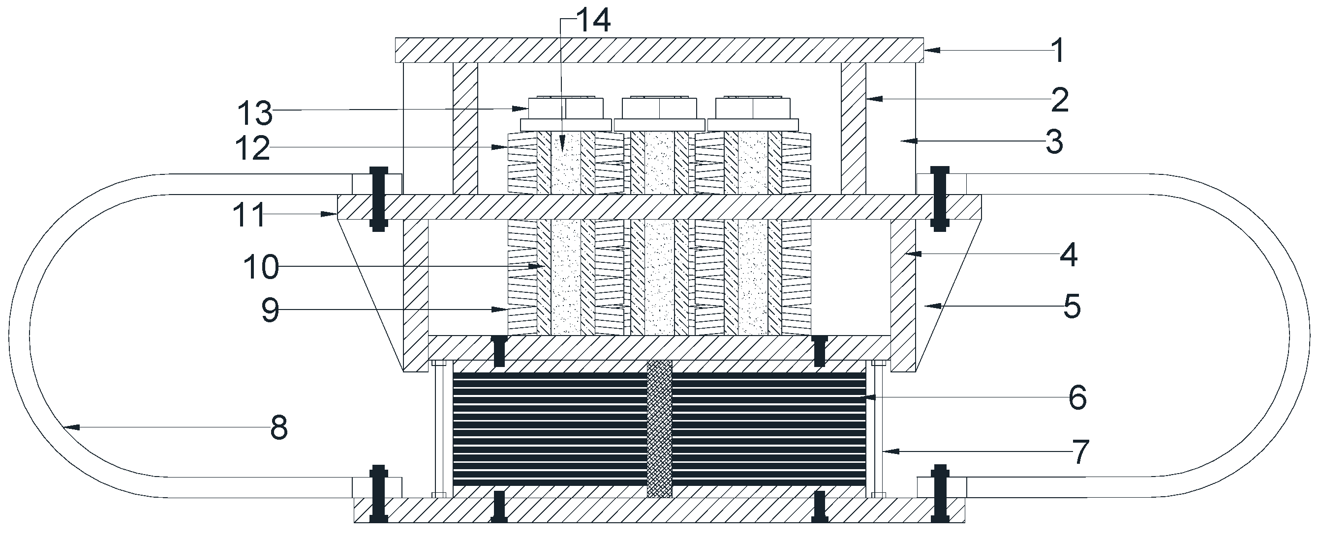
2.1. Configuration

The structural configuration of the 3D isolation bearing is illustrated in Figure 1. The bearing primarily consists of disc spring group 1, disc spring group 2, a lower LRB arranged in series, and U-shaped dampers, along with upper and lower sleeves made of steel plates and other auxiliary connecting components. Disc spring group 1 comprises five sets of disc springs, with each set containing two disc springs connected in parallel and four in series. Similarly, disc spring group 2 also includes five sets, where each set consists of four disc springs in parallel and four in series. Disc spring groups 1 and 2 are symmetrically mounted on the upper and lower sides of the middle steel plate, respectively. The upper end of the U-shaped damper is connected to the middle steel plate, while its lower end is fastened via bolts to the lower connection plate of the LRB. The upper sleeve is welded to the top plate and the middle steel plate, whereas the lower sleeve is welded to the middle steel plate and merely contacts the upper connection plate of the LRB. Five supporting shafts, comprising one centrally positioned shaft and four symmetrically distributed around it, pass through holes in the middle steel plate, with their lower ends welded to the upper connection plate of the LRB.

2.2. Working Mechanism

The working mechanism of the bearing can be analyzed from five key aspects: load-bearing capacity, horizontal isolation behavior, vertical isolation behavior, energy dissipation, and post-earthquake reparability. Regarding load-bearing capacity, disc spring group 2 provides sufficient vertical stiffness and strength to support the dead load of the superstructure. Under horizontal loading conditions, the LRB undergoes significant shear deformation, thereby elongating the structural natural period and dissipating seismic energy. In terms of vertical loading, when the bearing experiences compressive forces, disc spring group 2 is compressed while disc spring group 1 remains inactive. Conversely, under tensile loads, disc spring group 1 is compressed while disc spring group 2 does not work. This design enables the bearing to function as a specialized device for enhancing tensile performance. Consequently, the compressive deformations of disc spring groups 1 and 2 help mitigate vertical seismic responses. Additionally, the U-shaped dampers not only contribute supplementary damping but also moderately increase the initial stiffness of the bearing. Furthermore, upon yielding, the U-shaped dampers allow for adjustable horizontal and vertical stiffness characteristics and can be conveniently replaced after an earthquake.

3. Introduction to Specimen Design

3.1. Design of LRB

In this study, the dead load of the superstructure is set to 1000 kN. The basic parameters of LRB are presented in Table 1. The selected rubber has a Shore hardness of 40 HA. The lead core of LRB is made of lead with a purity exceeding 99.9%, a density of 11.3 × 10³ kg/m3, an elastic modulus of 1.7 × 10⁴ MPa, a Poisson’s ratio of 0.42, and a yield stress of 8.5 MPa. The internal steel layers, upper and lower sealing plates, and connecting plates are all made of Q355B steel, with a density of 7.8 × 10³ kg/m3, an elastic modulus of 2.1 × 10⁵ MPa, and a Poisson’s ratio of 0.3.

3.2. Disc Spring Groups 1 and 2

As previously mentioned, disc spring groups 1 and 2 are both assembled using individual disc springs. The selected disc springs belong to standard series A [36,37], made from high-strength 50 CrVA steel, with an elastic modulus of 2.06 × 10⁵ MPa, a Poisson’s ratio of 0.3, and a yield strength of 1400 MPa. The main parameters of the individual disc spring are summarized in Table 2.
To restrict horizontal displacements of the disc spring groups, five supporting shafts are employed. These supporting shafts utilize composite tubes constructed from 45# steel, each equipped with a matching hexagonal flange nut. The outer diameter of the selected steel tube corresponds to series 2 [36,37], with a dimension of 70 mm and a wall thickness of 17 mm. All steel tubes are filled with micro-expansion high-strength cement mortar.

3.3. U-Shaped Dampers

The U-shaped steel damper is manufactured from Q235B steel, characterized by an elastic modulus of 2.06 × 10⁵ MPa, a Poisson’s ratio of 0.3, and a density of 7.8 × 10³ kg/m3. The primary parameters of the U-shaped steel damper are listed in Table 3. The damper is connected to the middle or lower plate of the bearing via two M14 bolts. Additionally, since the middle and bottom plates feature evenly distributed holes along all four sides, it is convenient to symmetrically install 1, 2, or 4 U-shaped dampers on each side of the bearing in both horizontal directions.

3.4. Sleeves and Other Plates

As illustrated in Figure 1, the upper sleeve and stiffening ribs, the lower sleeve and stiffening ribs, as well as the upper and middle plates are all constructed from Q355B steel. The wall thickness of the sleeves is 30 mm, while the stiffening ribs have a thickness of 20 mm. Detailed dimensional specifications can be found in reference [38].

4. Finite Element Modeling

4.1. Material Constitutive Model

To develop the finite element model of the 3D bearing, five types of material models, including rubber, lead, steel plate, U-shaped dampers, and disc springs, are needed.
Due to the large Poisson’s ratio and entangled molecular chains, rubber materials can undergo large deformations without significant volume changes. They are approximately incompressible materials and have the characteristic of being regarded as isotropic bodies. Their mechanical properties can be characterized by their elastic strain energy. To simulate the hyper-elastic characteristics of the rubber material of LRB, the Mooney–Rivlin strain energy potential function is adopted. This function can be expressed as [39]:
W = C 10 ( I 1 3 ) + C 01 ( I 2 3 ) + ( J 1 ) 2 D 1
where W is the strain energy per unit volume; C10, C01, and D1 are temperature-dependent material parameters; I1 and I2 are the first and second deviatoric strain invariants, respectively; J denotes the elastic volume ratio. The material parameters are calculated to be C10 = 0.192 MPa, C01 = 0.048 MPa, and D1 = 0.002 mm2/N. Assuming rubber is incompressible, so J is taken as 1.
A bilinear elastic–plastic model is employed to simulate the behavior of the lead and U-shaped damper materials, whereas an elastic model is used for the other steel components. The corresponding material parameters are summarized in Table 4.
To simulate the vertical disc spring groups composed of stacked disc springs, one approach involves constructing a detailed finite element model of each individual disc spring. However, this method requires modeling the geometric dimensions, material properties, and interactions of each disc spring, resulting in high computational costs and convergence difficulties. Alternatively, a simplified spring element can be used. To reduce computational complexity, a simplified spring-damper element can be used to substitute each set of disc springs. Under normal conditions, the stiffness of each disc spring set can be considered constant and is calculated using the following equations [36]:
K s = 4 E 1 μ 2 t 3 K 1 D 2 h 0 t 2 3 h 0 t f t + 3 2 f t 2 + 1
K 1 = 1 π C 1 C 2 / C + 1 C 1 2 ln C
where E represents the elastic modulus of the disc spring; μ denotes Poisson’s ratio; t and h0 are the thickness and solid height of each disc spring, respectively; f denotes the deformation of each disc spring; C is the ratio of the outer diameter D to the inner diameter d; K1 is a correlation coefficient. For a disc spring set with m slices in parallel and n in series, its stiffness is equal to m times Ks divided by n.
Furthermore, the nonlinear damping effect of the disc spring group can be approximated using a constant damping coefficient assigned to each spring set [40]. Based on Equations (2) and (3), the stiffness of the simplified spring element for each set in disc spring group 1 is determined to be 18.19 kN/mm, with a damping coefficient of 1.28 kN/(mm/s). Considering disc spring group 2, the stiffness and damping coefficients of the simplified spring element of each set are 36.39 kN/mm and 30 kN/(mm/s), respectively.

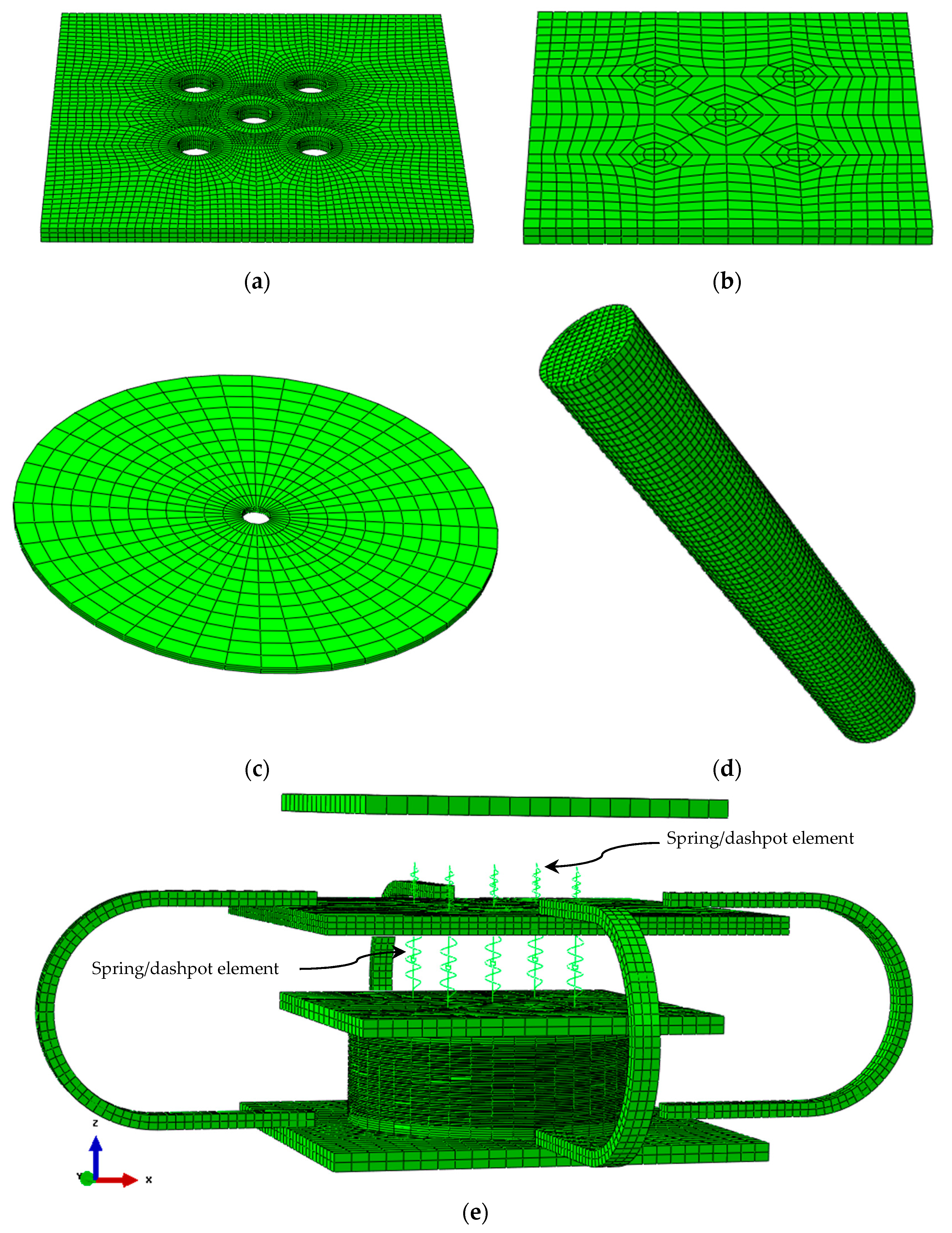
4.2. Element Type and Meshing

To establish a reliable finite element model, two key factors must be carefully considered in addition to employing accurate material constitutive models: first, the appropriate simplification of model components and the interaction mechanics between them; second, achieving an optimal balance between element mesh densities and computational efficiency [41,42]. The finite element model of the bearing is developed using ABAQUS (version 6.12) [39]. Based on the structural configuration and experimental observations of the bearings, the deformation of the bearings is mainly concentrated in the LRB, disc springs, and U-shaped dampers. Consequently, this study excluded non-critical components, namely, the supporting shafts, the upper and lower sleeves, as well as the corresponding stiffening ribs, from the finite element model to enhance computational efficiency and convergence performance. The functional roles of these components will be elaborated in the subsequent section.
Given that rubber exhibits typical nonlinear behavior and is nearly incompressible, the C3D8RH solid element is selected to define the inner rubber layer. The cover rubber of the LRB is neglected. In addition, the C3D8R solid element is employed to discretize the upper and lower plates, middle plate, closure plates, inner steel layers, upper connection plate of LRB, lead core, and U-shaped dampers. From the working mechanism of the bearing described earlier, it can be inferred that when the bearing is subjected to vertical compression, the disc spring group 2 is compressed, while the disc spring group 1 remains inactive. Conversely, under vertical tension, the disc spring set 1 is compressed, whereas the disc spring group 2 does not function. To accurately simulate the disc spring groups in this paper, the nonlinear spring/dashpot element, Spring A provided by ABAQUS software is employed. A total of ten such elements are implemented. Specifically, the upper five elements are utilized to replace the disc springs of group 1, and the lower five are employed to substitute the disc springs of group 2.
The detailed finite element model of the novel 3D bearing is illustrated in Figure 2a–e. It is worth mentioning that the mesh density of the closure plates, each rubber layer, and each internal steel layer of the LRB within the plane is the same, with 5, 3, and 1 layers defined along the thickness direction, respectively. To accurately capture the large plastic deformation of the lead core and obtain its stress and strain distributions, the mesh size was controlled within 2 mm, as shown in Figure 2d. Figure 2e presents the complete finite element model of the bearing, with only one U-damper connected to each side.

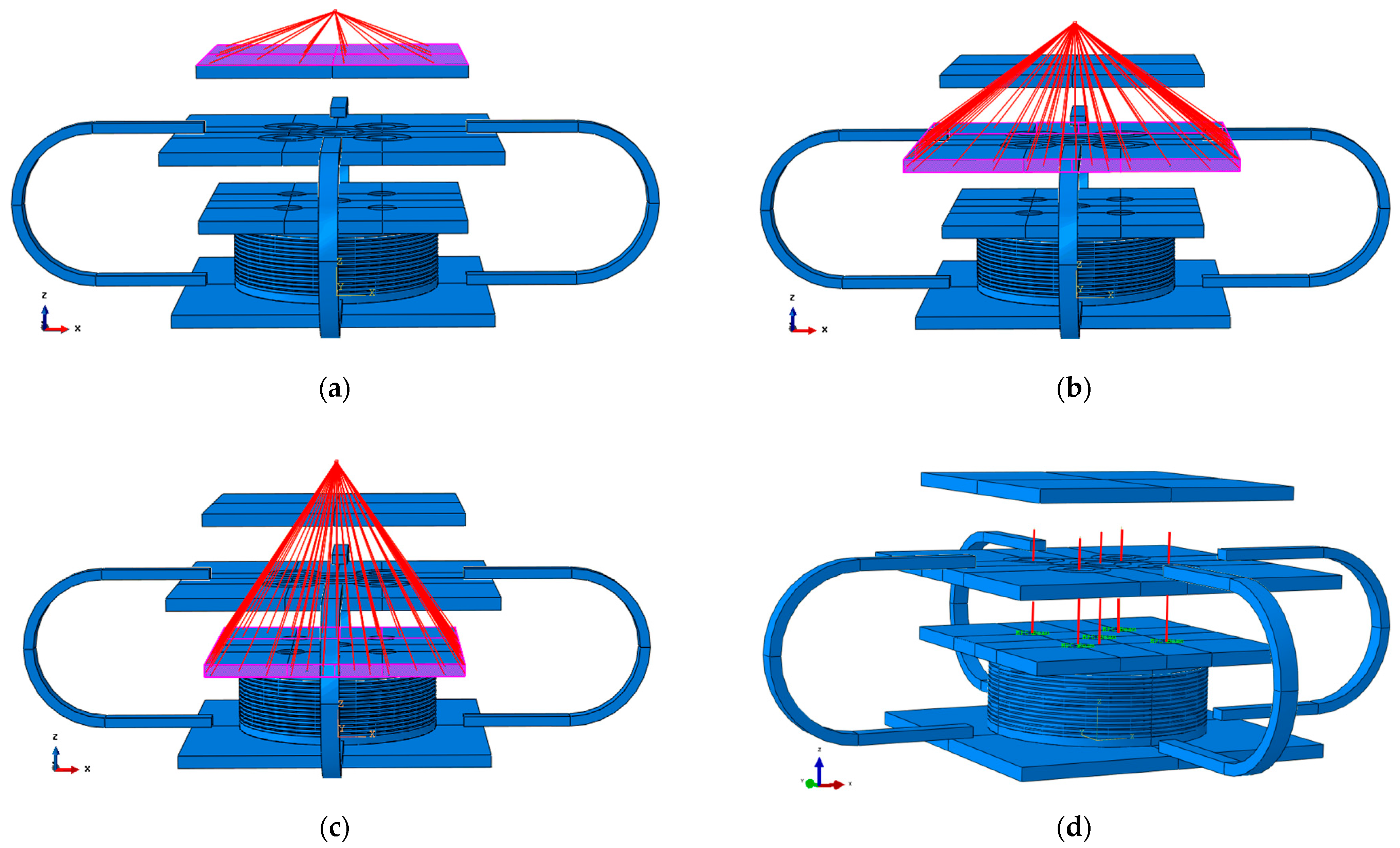
4.3. Definition of Interaction and Boundary Conditions

To ensure proper force transmission and deformation compatibility among the components, the following interaction definitions are established:
Firstly, kinematic coupling constraints are enforced separately between reference point 1 (RP-1) and the top surface of the upper plate, as well as between RP-1 and the side surfaces of the middle plate. In both cases, all six degrees of freedom, namely, U1, U2, U3, UR1, UR2, and UR3, are constrained. This approach effectively couples the deformations of the upper and middle plates, thereby eliminating the need to explicitly model the upper sleeve and related stiffeners. In addition, one more kinematic coupling constraint is implemented between RP-1 and the upper connection plate of the LRB. In this case, only the U3 degree of freedom (vertical direction) is left unconstrained, while the remaining five (U1, U2, UR1, UR2, and UR3) are constrained. This ensures that the upper connection plate of the LRB moves horizontally in conjunction with the upper and middle plates while allowing free vertical movement. As a result, the explicit modeling of the lower sleeve and related stiffeners was avoided. Details of these three coupling constraints are presented in Figure 3a–c.
Secondly, five MPC beam constraints were established on the upper connection plate of the LRB to simulate the disc spring shafts, as shown in Figure 3d. Ten reference points were defined at the center positions of the holes on the upper and lower surfaces of the middle plate to assign the spring elements. Among these, the upper five reference points serve as the lower nodes of the upper five spring elements, and the lower five reference points act as the upper nodes of the lower five spring elements. Each reference point is coupled with the annular region within a 70 mm radius around the corresponding hole on the upper and lower surfaces of the middle plate.
To establish the 23 coupling constraints mentioned above, a total of 21 reference points are employed. In the model of the LRB, the inner rubber layers and the inner steel layers, the upper and lower connection steel plates, the closure plates, and the lead core are all connected to each other by tie constraints. Finally, the upper end of the U-shaped dampers is connected to the middle steel plate, and the lower end is connected to the lower connection plate of the LRB. The connection method of both also uses tie constraints. For the boundary conditions of the bearing, all translational degrees of freedom of the lower connection plate are constrained, that is, U1 = U2 = U3 = 0.

5. Validation of FE Model

The experimental setup and a typical loading photograph are presented in Figure 4. To validate the accuracy of the finite element (FE) model, Figure 5a–c depict the comparison between the numerical results and the experimental outcomes regarding the horizontal hysteretic performance of the bearing under vertical loads of 1000 kN, 1200 kN, and 1500 kN, respectively. In each loading test, the maximum horizontal displacement is set to 98 mm for three cycles [43], with a loading frequency of 0.01 Hz. The test data shown in Figure 5 correspond to the third cycle of the compression–shear tests. Further analysis of Figure 5a reveals that the equivalent stiffness and peak force at 98 mm derived from the simulation are 7.8% and 13.55% higher than the experimental values, respectively. In Figure 5b, these differences are 2.9% and 10.92%, respectively. Similarly, in Figure 5c, the simulated equivalent stiffness and peak force exceed the experimental results by 2.9% and 8.2%, respectively.
Additionally, Figure 5d illustrates the hysteresis behavior of the bearing at various horizontal shear strain levels: 50%, 75%, 100% (i.e., 98 mm), 125%, and 150%, under a constant vertical load of 1000 kN. The comparison indicates that the numerical results are in good agreement with the experimental data. Therefore, it can be concluded that the finite element model accurately predicts the horizontal hysteretic behavior of the bearing.

6. Horizontal Performance Analysis

To comprehensively evaluate the influence of vertical loads, shear strains, and the number of U-shaped dampers on the horizontal isolation behavior of the 3D bearing, numerical simulations involving 12 loading cases are conducted, as summarized in Table 5.
Based on the numerical simulation results, the equivalent stiffness, equivalent damping ratio, and natural period of the 3D bearing in the horizontal direction can be further obtained. The formulas are as follows:
K eq , h = Q 1 Q 2 X + X
ζ eq , h = W h 2 π K h X 2
T h = 2 π F v g K h
where Keq,h, ζ eq , h and Th denote the equivalent stiffness, equivalent damping ratio, and natural period of the 3D bearing in the horizontal direction, respectively; Q1 and Q2 represent the positive and negative peak shear forces; X and -X are the positive and negative shear displacements corresponding to Q1 and Q2, respectively; Wh denotes the area of the hysteresis loop in the horizontal load–displacement curve; Fv represents the applied vertical load.

6.1. Different Vertical Loads

To investigate the horizontal hysteresis behaviors of the 3D bearing under varying load capacities, vertical loads of 1000 kN, 1200 kN, and 1500 kN are individually applied to the bearing. A sinusoidal excitation with a frequency of 0.01 Hz is horizontally applied in a displacement-controlled manner.
Figure 6a presents the horizontal hysteretic curves of the bearing under different vertical loads. It can be observed that the variations in vertical loading result in minimal differences in the horizontal load–displacement characteristics, indicating that the bearing’s horizontal hysteresis performance is not significantly affected by changes in the vertical load. This behavior is primarily due to the near-incompressibility of rubber and the reciprocating plastic shear deformation of the lead core. As the vertical load increases, the equivalent horizontal stiffness of the bearing exhibits a decreasing trend, as illustrated in Figure 6b. Regarding the horizontal equivalent damping ratio of LRBs, previous studies have indicated that when the pressure is below 10 MPa, the damping ratio increases linearly with pressure, while for pressures up to 15 MPa, the increase becomes nonlinear [44,45]. As shown in Figure 6c, the equivalent damping ratio increases with compressive stress, although the variation remains relatively small. This observation aligns with findings reported for LRBs. The natural period is closely related to the equivalent stiffness and is inversely proportional to the square root of the equivalent stiffness when the vertical load is constant. Consequently, its variation trend is evident, as demonstrated in Figure 6d.

6.2. Different Horizontal Shear Strains

To further investigate the horizontal hysteresis behaviors of the 3D bearing under different horizontal shear strains, the displacement-controlled loading method is utilized to simulate the behavior of the bearing under combined compressive and shear loading conditions. First, a vertical load of 1000 kN is applied, and then sinusoidal excitations are imposed incrementally. The selected peak shear strains are 50%, 75%, 100%, 125%, and 150%, respectively.
As shown in Figure 7a, under moderate shear strain conditions, the load–displacement curve of the bearing exhibits a fusiform shape without pinching or noticeable degradation in strength and stiffness. This phenomenon can be attributed to the contribution of the U-shaped dampers. Figure 7b illustrates that with increase in the shear strain, the equivalent horizontal stiffness of the bearing shows a decreasing trend. The reason is that the rubber molecular chains gradually untangle and align directionally, leading to softening, and the lead core constantly loses its ability to contribute stiffness. Figure 7c presents the variation law that as the shear strain changes from 50% to 150%, the equivalent damping ratio of the bearing changes from 12.06% to the maximum value of 13.27% when the shear strain is 75%, and then continuously decreases to 10.38%. This trend can be explained such that as the shear strain increases, the rubber, lead core, and U-shaped dampers transition from the elastic stage to the plastic stage and subsequently enter the hardening stage. This process initially leads to an increase in energy dissipation capacity, followed by a subsequent decrease.

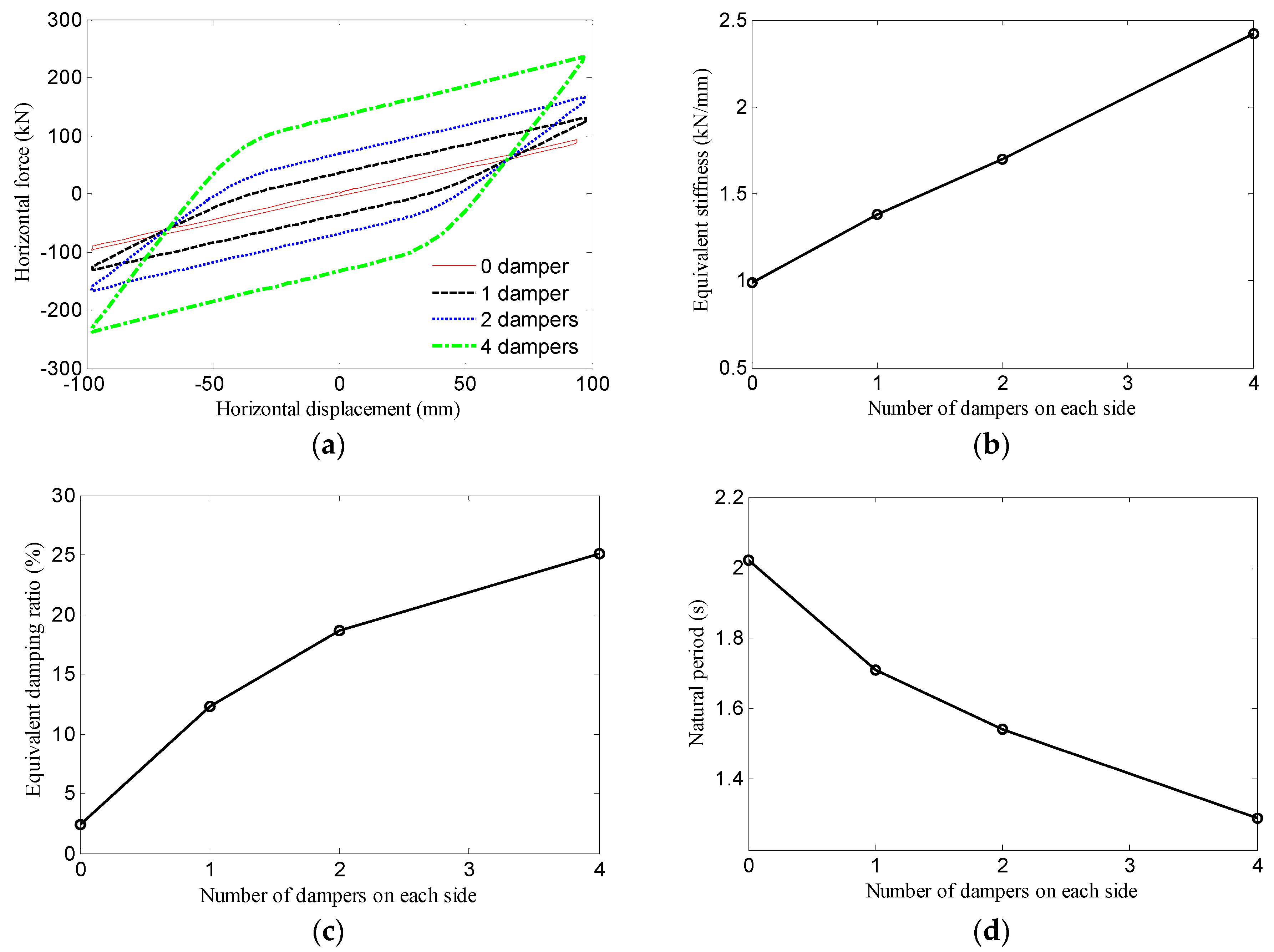
6.3. Different Numbers of U-Shaped Dampers

To further study the influence of the number of U-shaped dampers on the horizontal hysteresis performance of the bearings, compression–shear performance simulations are conducted for the bearings with different numbers of U-shaped dampers (see Figure 8), respectively. The loading is controlled by displacement, in sinusoidal form, with the peak shear strain taken as 100%. The vertical load of 1000 kN remains unchanged during the loading processes.
Figure 9 presents the horizontal behaviors of the 3D bearings with varying numbers of U-shaped dampers. It can be observed that as the number of U-shaped dampers increases, the energy dissipation capacity, equivalent horizontal stiffness, and equivalent damping ratio of the bearing all increase. Therefore, the U-shaped damper significantly enhances the horizontal isolation performance of the bearing discussed in this study. Notably, considering that the lead core diameter (30 mm) used in this bearing is considerably smaller than that of conventional lead rubber bearings (LRBs), the energy dissipation capacity of the bearing without U-shaped dampers is markedly limited in the horizontal direction, as demonstrated in Figure 9a. It is obvious that the addition of U-shaped dampers can partially substitute for the lead core. In this way, not only is the energy dissipation capacity of the bearing effectively improved, but also an environmentally sustainable design objective is achieved.

7. Vertical Performance Analysis

To explore the vertical isolation performance of the novel device, numerical simulations under 8 loading cases are carried out, as shown in Table 6.
Similarly, we can also obtain the equivalent stiffness, equivalent damping ratio, and natural vibration period of the bearings in the vertical direction according to the following formulas,
K eq , v = P 1 P 2 Y + Y
ζ eq , v = W v 2 π K v Y 2
T v = 2 π F v g K v
where Keq,v, ζ eq , v , and Tv are the equivalent vertical stiffness, equivalent damping ratio, and vertical natural period of the bearing; P1 and P2 are the maximum and minimum vertical forces; Y and -Y are the positive and negative vertical displacements corresponding to P1 and P2, respectively; Wv denotes the area enclosed by the vertical load–displacement hysteresis loop; Fv refers to the vertical loading force.

7.1. Different Vertical Displacements

Figure 10a displays the vertical hysteretic curve of the bearing, which exhibits a pronounced asymmetry. This characteristic arises since when the bearing is under tension, only spring group 1 is compressed, and when the bearing is under compression only spring group 2 is compressed. Moreover, spring group 1 and spring group 2 have different compressive stiffness. As shown in Figure 10b, with increasing amplitude of the tension–compression cycles, the equivalent stiffness of the bearing initially decreases and then increases. This phenomenon can be attributed to the transition of the rubber and lead core from the elastic phase to the yielding phase, combined with the hardening effect exhibited by the U-shaped dampers under large displacements. For similar reasons, the energy dissipation capacity in the vertical direction first increases and then decreases, as illustrated in Figure 10c.
Figure 11 presents the load–displacement hysteresis curves of spring groups 1 and 2 during the vertical tension–compression cyclic loading process of the bearing. The following observations can be made: (1) The mechanical behavior of the spring groups during the tension–compression cycles aligns with the intended design expectations. (2) Throughout the tension–compression cycles, the displacements of the spring groups remain lower than the overall vertical displacement of the bearing. For instance, when the bearing undergoes a tensile displacement of 6 mm, the displacements of the central and outer springs within group 1 are only 1.33 mm and 1.57 mm, respectively. This indicates that the vertical displacement of the LRB component ranges between 4.43 mm and 4.67 mm, thereby contributing to an enhancement in the tensile performance of the bearing. (3) Owing to the deformation of the middle plate, the reaction force generated in the central spring is always less than that generated in the outer springs.
Figure 12 shows the stress distributions of the inner rubber layers at different positive peak displacements of the tension–compression cyclic loading process of the bearing. It can be seen that the stress distribution has obvious symmetry, that is, the stress is the greatest at the center and gradually decreases along the radial direction. To precisely control the tensile stress on the rubber layer, careful design is needed.

7.2. Different U-Shaped Dampers

Figure 13 illustrates the vertical isolation performance of bearings equipped with varying numbers of U-shaped dampers. As shown in Figure 13a, the energy dissipation capacity does not significantly change with an increasing number of U-shaped dampers, indicating that these dampers have a limited effect on enhancing the vertical isolation performance of the bearings. In Figure 13b, it can be observed that the equivalent vertical stiffness of the bearings continues to increase as the number of dampers increases, which is primarily due to the initial stiffness provided by the U-shaped dampers. According to Figure 13c, the impact of the U-shaped dampers on the equivalent damping ratio of the bearings is relatively complex. Initially, increasing the number of dampers enhances the energy dissipation mechanism of the system, specifically through the plastic deformation of the U-shaped dampers. However, when the number of dampers becomes excessive, they remain predominantly in the elastic state, thereby reducing the overall energy dissipation capacity of the bearings.

8. Conclusions

This study proposes a novel 3D isolation bearing and develops its finite element model, followed by a series of simulation analyses. The main contributions are summarized as follows:
(1)
A finite element model of the 3D isolation bearing is established. Given the structural complexity of the bearing, certain components, such as the stiffened sleeves, disc springs, and support shafts, are simplified during the modeling process. The validity of the model is confirmed through comparison with existing experimental data. The results indicate that the finite element model can accurately predict the mechanical behavior of the bearing.
(2)
In terms of load-bearing capacity, the numerical analysis demonstrates that the proposed bearing provides stable load-carrying performance. The distribution of vertical loads between the LRB and U-shaped dampers can be flexibly adjusted by varying the number of dampers.
(3)
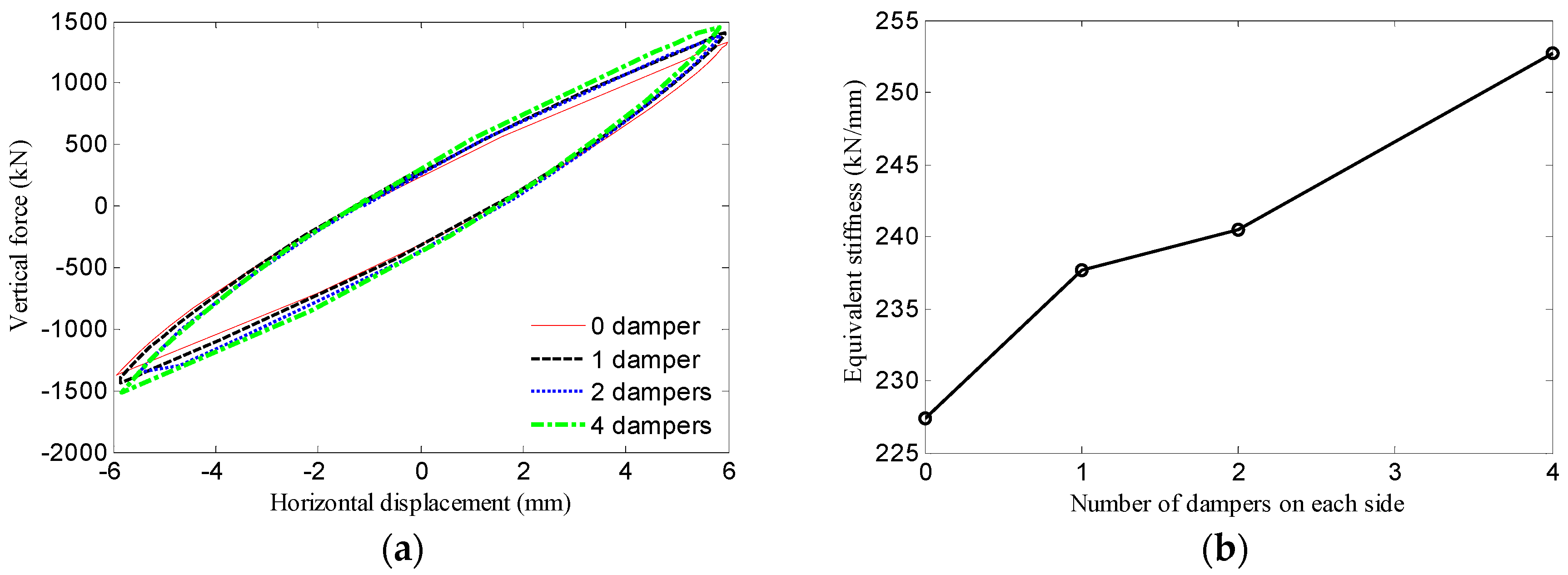
Under compressive-shear loading conditions, the bearing exhibits reliable energy dissipation characteristics. Although the small lead core design imposes limitations on energy dissipation, increasing the number of U-shaped dampers significantly enhances this capability. Specifically, compared with the bearing without U-shaped dampers, the energy dissipation capacity of the bearing increases by 628%, 1300%, and 2581% when employing 1, 2, and 4 dampers on each side, respectively.
(4)
With respect to vertical performance, the numerical results show that when the bearing is subjected to a tensile displacement of 6 mm, the displacement of the LRB remains within the range of 4.43 to 4.67 mm. This indicates that the disc spring group design effectively mitigates the tensile deformation of the LRB, thereby improving its tensile resistance. Additionally, the U-shaped dampers contribute minimally to vertical energy dissipation compared to their impact on the vertical stiffness and load-bearing capacity.
(5)
This study primarily employs finite element analysis to conduct a preliminary investigation into the mechanical properties of a new 3D bearing. To facilitate further research and practical application, future studies should include vertical performance testing, shaking table experiments, and theoretical analysis, which are urgently needed.

Author Contributions

Conceptualization, J.L. and L.S.; Methodology, Y.W., Y.C. and D.Q.; Software, J.L. and T.L.; Writing—original draft, T.L.; Writing—review and editing, J.L., Y.C., D.Q. and S.D. All authors have read and agreed to the published version of the manuscript.

Funding

This research received the support of the Natural Foundation of Shaanxi Province, China (No. 2025 JC-YBMS-535; No. 2014 JM7278).

Data Availability Statement

Data are contained within the article.

Conflicts of Interest

Authors Jianjun Li, Lvhong Sun, and Yanchao Wu were employed by the company CCCC First Highway Northwest Engineering Co., Ltd. The remaining authors declare that the research was conducted in the absence of any commercial or financial relationships that could be construed as a potential conflict of interest.

References

  1. Pan, P.; Zeng, Y.; Cao, Y.R.; Ai, H.H.; Wang, H.S. State-of-the-art of research on the building structure isolation technologies. Eng. Mech. 2024, 41, 39–54. (In Chinese) [Google Scholar]
  2. Collier, C.J.; Elnashai, A.S. A procedure for combining vertical and horizontal seismic action effects. J. Earth Eng. 2001, 5, 521–539. [Google Scholar] [CrossRef]
  3. Li, N.; Liu, H.G.; Liu, P.; Li, Z.X.; Xie, L.L. Statistical analysis of vertical ground motion characteristics in near-fault regions. Chin. Civ. Eng. J. 2020, 53, 120–128. (In Chinese) [Google Scholar]
  4. Seigenthaler, R. Earthquake-proof building supporting structure with shock absorbing damping elements. Schweiz. Bauztg. 1970, 20, 211–219. [Google Scholar]
  5. Aiken, I.D.; Kelly, J.M.; Tajirian, F.F. Mechanics of Low Shape Factor Elastomeric Seismic Isolation Bearings; Report No. UCB/EERC-89/13; University of California: Berkeley, CA, USA, 1989. [Google Scholar]
  6. Lu, Z.; Liang, Q.Y.; Zhou, Y.; Luo, W.L.; Li, J.R.; Jiang, K. Novel thick layer damping rubber bearing (TLDRB) with reduced vertical stiffness: Laboratory tests and mechanical models. J. Build. Struct. 2024, 94, 109839. [Google Scholar] [CrossRef]
  7. Huffmann, G. Full base isolation for earthquake protection by helical springs and viscodampers. Nucl. Eng. Des. 1985, 84, 331–338. [Google Scholar] [CrossRef]
  8. Fujita, S.; Minagawa, K.; Tanaka, G.; Shimosaka, H. Intelligent seismic isolation system using air bearings and earthquake early warning. Soil Dyn. Earthq. Eng. 2011, 31, 223–230. [Google Scholar] [CrossRef]
  9. Mo, Z.; Lai, B.L.; Shu, G.P.; Yang, T.Y.; Ventura, C.E.; Richard Liew, J.Y. Enhancing seismic resilience in modular steel building through three-dimensional isolation. Eng. Struct. 2025, 323, 119269. [Google Scholar] [CrossRef]
  10. Zhou, Z.G.; Wong, J.; Mahin, S. Potentiality of using vertical and tree-dimensional isolation systems in nuclear structures. Nucl. Eng. Technol. 2016, 48, 1237–1251. [Google Scholar] [CrossRef]
  11. Fujita, S.; Kato, E.; Kashiwazaki, A.; Shimoda, I.; Sasaki, K. Shake table tests on three-dimensional vibration isolation system comprising rubber bearing and oil spring. In Proceedings of the 11th World Conference on Earthquake Engineering, Acapulco, Mexico, 23–28 June 1996; pp. 23–28. [Google Scholar]
  12. Xiong, S.S. Theoretical and Experimental Research of Three-Dimensional Seismic Base Isolation System. Ph.D. Thesis, Huazhong University of Science and Technology, Wuhan, China, 2004. (In Chinese). [Google Scholar]
  13. Zhao, Y.M.; Su, J.Y.; Lu, M. Experimental study on three-dimensional base-isolated model with 3DIB. Adv. Mater. Res. 2011, 255–260, 2325–2329. [Google Scholar] [CrossRef]
  14. Yan, X.Y.; Zhang, Y.S.; Wang, H.D.; Wei, L.S. Experimental study on high-rise structure with three-dimensional base isolation and overturn resistance devices. J. Build. Struct. 2009, 30, 4–11. (In Chinese) [Google Scholar]
  15. Xue, S.D.; Chang, L.H.; Li, X.Y.; Liang, S.Z. Research on mechanical characteristics of anti-extraction three-dimensional seismic isolation bearing. Build. Struct. 2022, 52, 81–87. (In Chinese) [Google Scholar]
  16. Jia, J.F.; Ou, J.P.; Liu, M.; Zhang, Z. Mechanical performance tests of a novel three-dimensional isolation bearing. J. Civ. Archit. Environ. Eng. 2012, 34, 29–34, 53. (In Chinese) [Google Scholar]
  17. Liu, H.Q. SMA Strands-Laminated Rubber Compound Bearing and Its Seismic Isolation Behavior. Ph.D. Thesis, Tianjin University, Tianjin, China, 2006. (In Chinese). [Google Scholar]
  18. Kashiwazaki, A.; Tanaka, M.; Tokuda, N. Shaking test of seismic isolation floor system by using 3-dimensional isolator. In Proceedings of the Ninth World Conference on Earthquake Engineering, Tokyo and Kyoto, Japan, 2–9 August 1988; pp. 845–850. [Google Scholar]
  19. Shu, G.P.; Lai, B.L.; Ventura, C.E.; Yang, T.Y. Experimental behavior, numerical modeling and parameters evaluation of three-dimensional seismic isolation device. J. Constr. Steel Res. 2024, 220, 108817. [Google Scholar] [CrossRef]
  20. Liu, W.G.; Xu, H.; He, W.F.; Yang, Q.R. Static test and seismic dynamic response of an innovative 3D seismic isolation system. J. Eng. Struct. 2018, 144, 04018212. [Google Scholar] [CrossRef]
  21. Xu, H.; He, W.F.; Zhang, L.L.; Liu, W.G. Shaking table test of an novel three-dimensional seismic isolation system with inclined rubber bearings. Eng. Struct. 2023, 293, 116609. [Google Scholar] [CrossRef]
  22. Chen, Z.; Ding, Y.; Shi, Y. A vertical isolation device with variable stiffness for long-span spatial structures. Soil Dyn. Earthq. Eng. 2019, 123, 543–558. [Google Scholar] [CrossRef]
  23. Liang, Q.H.; Luo, W.L.; Zhou, Y.; Ke, X.B.; Li, J.R. Seismic performance of a novel three-dimensional isolation bearing. J. Build. Struct. 2022, 57, 104818. [Google Scholar] [CrossRef]
  24. Wei, Y.Y.; Wang, X.P.; Wu, H.B.; Liu, B.; Zhu, N.H. A new sliding three-dimensional seismic isolation bearing mechanical model and its seismic performance. Structures 2025, 72, 108216. [Google Scholar] [CrossRef]
  25. Luo, W.L.; Liang, Q.H.; Zhou, Y.; Lu, Z.C.; Li, J.R.; He, Z.M. A novel three-dimensional isolation bearing for buildings subject to metro- and earthquake-induced vibration: Laboratory test and application. J. Build. Eng. 2024, 86, 108798. [Google Scholar] [CrossRef]
  26. Gao, Y. Design and Research of a Three-Dimensional Seismic Isolation Bearing. Master’s Thesis, Taiyuan University of Technology, Taiyuan, China, 2019. (In Chinese). [Google Scholar]
  27. Ge, G.Y. Study on the Mechanical Properties and Isolation Performance of Three-Dimensional Isolation Support. Master’s Thesis, Xihua University, Chengdu, China, 2006. (In Chinese). [Google Scholar]
  28. Han, Q.; Jing, M.; Lu, Y.; Liu, M. Mechanical behaviors of air spring-FPS three-dimensional isolation bearing and isolation performance analysis. Soil Dyn. Earthq. Eng. 2021, 149, 106872. [Google Scholar] [CrossRef]
  29. Cao, Y.; Pan, P.; Sun, J.; Wang, H. Mechanical properties and isolation effect of disc spring-single friction pendulum 3D vibration isolation device. J. Build. Struct. 2022, 7, 44–53. [Google Scholar]
  30. Cao, Y.R.; Pan, P.; Wang, H.S.; Sun, J.B.; Xiao, G.Q.; Zuo, Z.F. Development of an innovative three-dimensional vibration isolation bearing. Eng. Struct. 2023, 295, 116890. [Google Scholar] [CrossRef]
  31. Kitayama, S.; Lee, D.H.; Constantinou, M.C.; Kempner, L., Jr. Probabilistic seismic assessment of seismically isolated electrical transformers considering vertical isolation and vertical ground motion. Eng. Struct. 2017, 152, 888–900. [Google Scholar] [CrossRef]
  32. Zhou, Y.; Chen, P.; Mosqueda, G. Numerical studies of Three-Dimensional isolated structures with vertical Quasi-Zero stiffness property. J. Earthq. Eng. 2022, 26, 3601–3622. [Google Scholar] [CrossRef]
  33. Yu, T.H.; Zhang, C.; Huang, Z.Q.; Huang, W.Y.; Wang, S.Y.; Zhong, G.Q.; Qu, D.T. Experimental and numerical studies of a novel three-dimensional isolation device incorporating disc springs with U-shaped dampers. Soil Dyn. Earthq. Eng. 2023, 174, 108164. [Google Scholar] [CrossRef]
  34. Yu, T.H.; Huang, Z.Q.; Zhang, C.; Huang, W.Y.; Bao, W.; Liu, Y.Y. Numerical investigation of three-dimensional isolator and mitigation for single-layer lattice shell structure. Structures 2024, 62, 106235. [Google Scholar] [CrossRef]
  35. Sha, M.; Guan, M.S.; Lin, M.J.; Tan, X.Y.; Chen, X.S. Experimental study on the performance of innovative self-centering three-dimensional isolation bearing. Structures 2024, 69, 107587. [Google Scholar] [CrossRef]
  36. GB/T 1972.1-2023; Disc Spring—Part 1: Calculation. China National Standards: Beijing, China, 2023. (In Chinese)
  37. GB/T 1972.2-2023; Disc Spring—Part 2: Technical Specifications. China National Standards: Beijing, China, 2023. (In Chinese)
  38. Mu, J.J. Design and Mechanical Property Research of a New Three-Dimensional Seismic Isolation Bearing. Master’s Thesis, Hainan University, Haikou, China, 2024. (In Chinese). [Google Scholar]
  39. ABAQUS. ABAQUS Standard User’s Manual; Version 6.12; Dassault Systems Simulia Corporation: Providence, RI, USA, 2012. [Google Scholar]
  40. Xing, J.H.; Huang, H.; Zhang, J.Y.; Yang, Q.S. Mechnical properties of disc springs. J. Vib. Shock 2015, 34, 167–172. (In Chinese) [Google Scholar]
  41. Bagheri, M.; Jamkhaneh, M.E.; Samali, B. Effect of Seismic Soil-Pile-Structure Interaction on Mid- and High-Rise Steel Buildings Resting on a Group of Pile Foundations. Int. J. Geomech. 2018, 18, 04018103. [Google Scholar] [CrossRef]
  42. Asgari, A.; Ranjbar, F.; Bagheri, M. Seismic resilience of pile groups to lateral spreading in liquefiable soils: 3D parallel finite element modeling. Structures 2025, 74, 108578. [Google Scholar] [CrossRef]
  43. GB/T 20688.1-2007; Rubber Bear—Part 1: Seismic-Protection Isolators Test Methods. China National Standards: Beijing, China, 2007. (In Chinese)
  44. Benzoni, G.; Casarotti, C. Effects of vertical load, strain rate and cycling on the response of Lead-Rubber seismic isolators. J. Earthq. Eng. 2009, 13, 293–312. [Google Scholar] [CrossRef]
  45. Kircher, C. Chapter 12: Seismically Isolated Structures. In FEMA P-751, 2009 NEHRP Recommeded Provisions: Design Examples; BSSC: Washington, DC, USA, 2012; pp. 1–63. [Google Scholar]
Figure 1. Structural configuration of 3D bearing. 1–Upper plate; 2–Upper sleeve; 3–Stiffeners for upper sleeve; 4–Lower sleeve; 5–Stiffeners for lower sleeve; 6–LRB; 7–Wire rope; 8–U-shaped damper; 9–Disc spring group 2; 10–Supporting shaft; 11–Middle plate; 12–Disc spring group 1; 13–Hexagon nut; 14– High-strength cement mortar.
Buildings 15 02553 g001
Figure 2. Finite element model of bearing. (a) Middle plate; (b) Upper connection plate of LRB; (c) Rubber layer of LRB; (d) Lead core of LRB; (e) Complete FE model.
Buildings 15 02553 g002
Figure 3. Coupling constraints of bearing. (a) Coupling constraint for upper plate; (b) Coupling constraint for middle plate; (c) Coupling constraint for upper connection plate of LRB; (d) MPC beam coupling constraints.
Buildings 15 02553 g003
Figure 4. Experimental setup and typical photograph: (a) Experimental setup; (b) Typical compression—shear test at 100% strain level under vertical load of 1000 kN.
Buildings 15 02553 g004
Figure 5. Experimental and numerical horizontal hysteretic curves: (a) Under vertical load of 1000 kN; (b) Under vertical load of 1200 kN; (c) Under vertical load of 1500 kN; (d) At five shear strain levels: 50%, 75%, 100%, 125%, 150% under vertical load of 1000 kN.
Buildings 15 02553 g005
Figure 6. Horizontal performance of bearing under different vertical loads. (a) Hysteretic curves; (b) Equivalent stiffness; (c) Equivalent damping ratio; (d) Natural period.
Buildings 15 02553 g006aBuildings 15 02553 g006b
Figure 7. Horizontal performance of bearing under different shear strains. (a) Hysteretic curve; (b) Equivalent stiffness; (c) Equivalent damping ratio; (d) Natural period.
Buildings 15 02553 g007aBuildings 15 02553 g007b
Figure 8. Finite element models with varying numbers of dampers on each side. (a) 0 damper. (b) 2 dampers. (c) 4 dampers.
Buildings 15 02553 g008
Figure 9. Horizontal Performance of bearing with different numbers of U-shaped dampers. (a) Hysteretic curves; (b) Equivalent stiffness; (c) Equivalent damping ratio; (d) Natural period.
Buildings 15 02553 g009
Figure 10. Vertical performance of bearing under different displacement amplitudes. (a) Hysteretic curve; (b) Equivalent stiffness; (c) Equivalent damping ratio; (d) Natural period.
Buildings 15 02553 g010aBuildings 15 02553 g010b
Figure 11. Vertical hysteretic curves of springs. (a) Central springs; (b) Outer springs.
Buildings 15 02553 g011
Figure 12. Stress distributions of rubber layers under different positive displacement amplitudes. (a) +1 mm; (b) +2 mm; (c) +4 mm; (d) +6 mm.
Buildings 15 02553 g012aBuildings 15 02553 g012b
Figure 13. Vertical performance of bearing with different numbers of U-shaped dampers. (a) Hysteretic curves; (b) Equivalent stiffness; (c) Equivalent damping ratio; (d) Natural period.
Buildings 15 02553 g013aBuildings 15 02553 g013b
Table 1. Main parameters of LRB.
Diameter
(mm)
Lead Core Diameter
(mm)
Thickness of Rubber
Layer (mm)
Internal Plate
Thickness (mm)
Rubber Layer
Numbers
Rubber Shear
Modulus (MPa)
5003073140.4
Table 2. Main parameters of single disc spring.
Outside
Diameter (mm)
Inside
Diameter (mm)
Thickness
(mm)
Ultimate Displacement
(mm)
Free Altitude
(mm)
Bearing Capacity
(kN)
1407283.211.285.3
Table 3. Main parameters of U-shaped steel damper.
Radius of Arc Segment (mm)Breadth (mm)Thickness (mm)Straight Section Length (mm)
1754025220
Table 4. Material parameters of steel plate, lead, and U-shaped steel damper.
MaterialElastic Modulus (GPa)Poisson’s RatioYield Stress (MPa)Hardening Modulus (MPa)
Steel plate206.000.30355-
Lead17.000.428.5017.00
U-shaped damper206.000.30298.882060
Table 5. Parametric analysis in horizontal direction.
Parameter ClassificationLoad Case NumberConstant Vertical Force (kN)Horizontal Displacement (mm)Equivalent Horizontal Stiffness (kN/mm)Equivalent Horizontal Damping ratio (%)Horizontal Natural
Period
(s)
Vertical load11000[−98, +98]1.3812.281.71
21200[−98, +98]1.3712.341.88
31500[−98, +98]1.3612.532.11
Shear strain41000[−47, +47]1.7112.061.53
51000[−74, +74]1.4713.271.66
61000[−98, +98]1.3812.281.71
71000[−123, +123]1.2811.411.77
81000[−147, +147]1.2410.381.80
0 damper91000[−98, +98]0.992.352.02
1 damper101000[−98, +98]1.3812.281.71
2 dampers111000[−98, +98]1.7018.621.54
4 dampers121000[−98, +98]2.4225.051.29
Table 6. Parametric analysis in the vertical direction.
Parameter ClassificationLoad Case NumberVertical Displacement (mm)Equivalent Vertical Stiffness (kN/mm)Equivalent Vertical Damping Ratio (%)Vertical Vibration
Period
(s)
Vertical displacement1[−1, +1]232.689.590.132
2[−2, +2]220.8011.530.146
3[−4, +4]229.3410.360.137
4[−6, +6]237.669.340.130
0 damper5[−6, +6]227.369.080.133
1 damper6[−6, +6]237.669.340.130
2 dampers7[−6, +6]240.4910.550.129
4 dampers8[−6, +6]252.729.650.126
Disclaimer/Publisher’s Note: The statements, opinions and data contained in all publications are solely those of the individual author(s) and contributor(s) and not of MDPI and/or the editor(s). MDPI and/or the editor(s) disclaim responsibility for any injury to people or property resulting from any ideas, methods, instructions or products referred to in the content.

