Article

Finite Element Analysis of the Mechanical Performance of an Innovative Beam-Column Joint Incorporating V-Shaped Steel as a Replaceable Energy-Dissipating Component

1
School of Civil Engineering, Hebei University of Engineering, No. 19, Taiji Road, Shangbi Town, Economic and Technological Development Zone, Handan 056000, China
2
School of Construction Management, Purdue University, West Lafayette, IN 47906, USA
3
Department of Economics and Management, North China Electric Power University, No. 619, Yonghua North Street, Baoding 071003, China
*
Author to whom correspondence should be addressed.
Buildings 2025, 15(14), 2513; https://doi.org/10.3390/buildings15142513
Submission received: 26 June 2025 / Revised: 10 July 2025 / Accepted: 13 July 2025 / Published: 17 July 2025
(This article belongs to the Section Building Structures)

Abstract

Ductile structures have demonstrated the ability to withstand increased seismic intensity levels. Additionally, these structures can be restored to their operational state promptly following the replacement of damaged components post-earthquake. This capability has been a subject of considerable interest and focus in recent years. The study presented in this paper introduces an innovative beam-column connection that incorporates V-shaped steel as the replaceable energy-dissipating component. It delineates the structural configuration and design principles of this joint. Furthermore, the paper conducts a detailed analysis of the joint’s failure mode, stress distribution, and strain patterns using ABAQUS 2022 finite element software, thereby elucidating the failure mechanisms, load transfer pathways, and energy dissipation characteristics of the joint. In addition, the study investigates the impact of critical design parameters, including the strength, thickness, and weakening dimensions of the dog-bone energy-dissipating section, as well as the strength and thickness of the V-shaped plate, on the seismic behavior of the beam-column joint. The outcomes demonstrate that the incorporation of V-shaped steel with a configurable replaceable energy-dissipating component into the traditional dog-bone replaceable joint significantly improves the out-of-plane stability. Concurrently, the V-shaped steel undergoes a process of gradual flattening under load, which allows for a larger degree of deformation. In conclusion, the innovative joint design exhibits superior ductility and load-bearing capacity when contrasted with the conventional replaceable dog-bone energy-dissipating section joint. The joint’s equivalent viscous damping coefficient, ranging between 0.252 and 0.331, demonstrates its robust energy dissipation properties. The parametric analysis results indicate that the LY160 and Q235 steel grades are recommended for the dog-bone connector and V-shaped steel connector, respectively. The optimal thickness ranges are 6–10 mm for the dog-bone connector and 2–4 mm for the V-shaped steel connector, while the weakened dimension should preferably be selected within 15–20 mm.

1. Introduction

Within structural systems, connection joints act as vital force transfer points between components, significantly influencing the overall performance and safety of the structure. They represent a critical aspect of structural design. Historical earthquake damage assessments have indicated that conventional beam-column connection joints did not form the necessary plastic hinges to absorb seismic energy, thereby ensuring structural integrity. Instead, these joints often suffered brittle failures at the welded connections of beams and columns [1]. In response to these issues, experts and scholars globally have proposed more rigorous standards regarding welding quality, weld strength, and the configuration of welding backing components. Moreover, research has highlighted that, when plastic bending moments occur at the beam ends, the weld groove at the lower flange is subjected to excessively high stress levels, further compromising joint integrity [2]. Consequently, some researchers are exploring modifications in joint design that move plastic hinges outward, thereby mitigating stress concentrations at the beam flange weld grooves.
Currently, the industry predominantly employs two methodologies to facilitate the outward movement of plastic hinges: the reinforced design approach and the weakened design approach. This study delves into the flange-weakened joint, a subject of considerable research, colloquially referred to as the dog-bone joint due to its characteristic configuration. The dog-bone weakened beam section represents a typical weakened design approach that effectively moves the plastic hinge outward from the joint area. This strategy effectively mitigates the risk of brittle fracture failures at the beam ends, thereby ensuring the integrity of the beam-column joint. It facilitates a failure mode characterized by concentrated and manageable damage, which is considered ideal [3]. The experimental research conducted by Popov et al. [4] and Shen et al. [5] on the dog-bone weakened joint revealed that, when the weakened portion of the beam flange comprised only 35% to 45% of the flange’s total width, the overall stiffness of the steel frame experienced a reduction of merely 4% to 5%. This condition notably enhanced the achievement of an ideal failure mode characterized by concentrated and manageable damage. The study conducted by Chen et al. [6] involved a comparative analysis of the tapered dog-bone weakened joint and the circular arc dog-bone weakened joint. The findings indicated that both types of dog-bone joints are capable of producing substantial plastic rotation angles. However, the circular arc weakening method was deemed more practical than the tapered weakening method.
In recent times, it has been observed by numerous scholars that seismic activity induces significant plastic deformation in structures, irrespective of the joint configuration employed. The complexity and cost associated with repairing such damage have prompted the development of the concept of ductile structures by researchers worldwide. In ductile structures, plastic damage is concentrated within energy-dissipating components [7,8,9,10,11]. Post-seismic recovery is expedited by the replacement of these damaged components, thereby restoring the functionality of the structure in a timely and efficient manner. Chen et al. [12] proposed the use of replaceable buckling-restrained plates for energy dissipation. Their results proved that the fuse plates could be quickly replaced after testing, and the seismic performance of the repaired joint was almost the same as that of the original joint. Yu et al. [13] and Li et al. [14] implemented angel steel with a central weakened section as the joint connecting and energy-dissipating component within the upper and lower flanges of the beam. Their experimental outcomes indicated that this angel steel functioned as an “insurance fuse,” effectively safeguarding the main structural components from damage. Similarly, Men et al. [15] have developed a new type of steel beam-to-column joint with replaceable T-shaped short tube connectors. The experimental findings corroborate that the functionality of the joint can only be effectively restored through the replacement of the T-shaped steel connector. Cui et al. [16], Feng et al. [17], Zhang et al. [18], Yi et al. [19], Hou et al. [20] and Wang et al. [21,22] utilized bolted energy-dissipating components to link the beam sections at the flange level. Their research involved corresponding experimental validation or finite element analysis to substantiate the joint’s damage control capabilities. The research outcomes indicate that the energy-dissipating components effectively mitigate the plastic damage of the structure, ensuring that the primary structure remains in an elastic state. Current replaceable beam-column joints demonstrate a relatively ideal capacity for damage control and restoration of joint functionality through component replacement. However, these joints exhibit relative complexity and present opportunities for enhancement in terms of plastic deformation, ductility, and energy dissipation capacity. Currently, the widely studied T-joint [23] beam-column connections are prone to bolt slippage, leading to severe stiffness degradation. BRB (buckling-restrained brace) joint [24] beam-column connections require additional support space and are typically used as independent structural components, rather than as connections. Replacing them involves dismantling the entire brace, complicating the construction process.
This paper presents a novel beam-column joint configuration utilizing V-shaped steel as the replaceable energy-dissipating components. This configuration integrates V-shaped steel web members with a dog-bone weakened flange to achieve damage control and facilitate easy replacement. ABAQUS 2022 finite element software is employed to analyze the working mechanism and mechanical behavior of this joint. Furthermore, the influence of critical design parameters, including the thickness of the weakened flange member, material strength, weakened size, and thickness of the V-shaped steel, on the seismic performance of the node is examined, and relevant design recommendations for the structure are offered. This is intended to provide a valuable reference for ongoing engineering projects and corresponding research activities.

2. Joint Structure and Design Methods

2.1. Joint Structure and Construction Process

This paper presents a new design for beam-column connection joints, which is the result of a comprehensive evaluation of existing node forms and is founded on the principles of plastic hinge outward movement theory. The proposed design features V-shaped steel as the replaceable energy dissipation component. This innovative joint configuration comprises three integral components: a square concrete-filled steel tube column, a dog-bone style weakened connector, and a V-shaped steel connector. The connection between the square concrete-filled steel tube column and the terminal H-shaped steel beam is achieved through welding, creating a cantilever beam section in the process. The additional dog-bone weakened connectors and V-shaped steel connectors are fastened using high-strength bolt assemblies. These parts are designed for prefabrication in a factory setting and subsequent on-site assembly, providing advantages such as straightforward installation procedures and a significant level of assembly efficiency. The factory-prefabricated column incorporating a cantilever beam section acts as a temporary support and positioning device. This design significantly aids in the swift installation of components and enhances the convenience of construction operations [25,26].
Before the joint assembly, the cantilever beam section is securely welded to the external surface of the square steel tube with full-penetration welds on the upper and lower aspects. The connection to the steel beam is achieved using high-strength bolts, which are engaged through the dog-bone weakened connector and the V-shaped steel connector. At the construction site, when the steel beam is being hoisted, it is positioned to align with the extended section. The web of the beam is then matched with the V-shaped steel member and securely connected using high-strength bolts. After the joint is assembled, the assembly is completed by tightening the high-strength bolts. The overall assembly flow chart of the node is shown in Figure 1. The cantilever beam section is welded beforehand in a factory setting, thereby guaranteeing the integrity and quality of the welds.

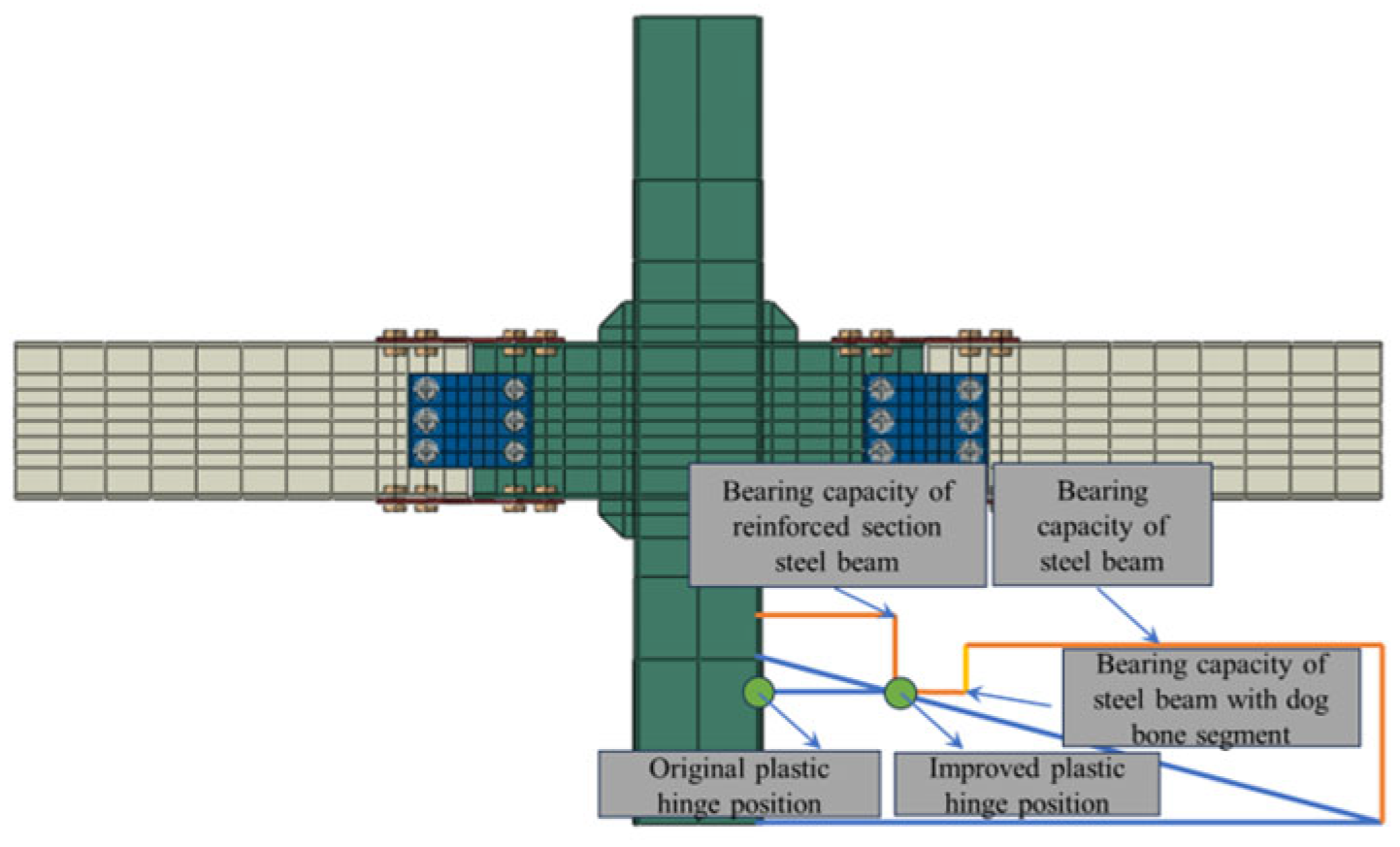
2.2. Design Principles

This innovative joint type is classified as a replaceable and easily repairable form, which also has the feature of concentrating damage in defined areas following seismic events. The design principles for this joint are analogous to the principles governing joints with plastic hinges that exhibit outward movement, as illustrated in Figure 2. The bending moment (M) induced by the external load at the terminus of the beam within a given point along the steel beam exhibits a direct relationship with the distance between that point and the beam’s end. In the event of no alteration to the cross-sectional dimensions of the steel beam, the beam’s flexural capacity (Mu) will remain constant. The initial plastic hinge is anticipated to develop at the location of the maximum M/Mu ratio, namely the core region of the joint. The implementation of the V-shaped steel and the dog-bone weakened connector serves to diminish the strength of the steel beam. Consequently, the strength of the spliced energy dissipation section decreases, facilitating the transfer of the plastic hinge from the central area of the node to the spliced energy dissipation beam section [27]. This process realizes the outward movement of the plastic hinge. In the presence of reciprocating loads on the beam section, the damage associated with plastic energy dissipation from bending moments and shear forces at the beam’s terminus is localized at the dog-bone weakened and V-shaped steel connector.
In the analysis, the joint configuration of the central column is selected. The H-shaped steel beam dimensions are 300 × 150 × 5.5 × 8, the square steel tube column dimensions are 250 × 250 × 10, and the bolt specification is M20 friction-type high-strength bolts (units in millimeters). After verification, the beams, columns and designs all meet the design requirements of strong column and weak beam, and strong joint and weak component stipulated in the Code for Seismic Design of Buildings (GB50011-2010 (2016)) [28]. The bolt hole spacing between each component meets the size requirements stipulated in the Standard for Design of Steel Structures (GB50017-2017) [29]. The dimensions of each component in mm are shown in Figure 3. The joint design concept simultaneously satisfies three international seismic standards: (1) compliance with AISC 341 requirements for Special Moment Frames, (2) achievement of Dissipative Capacity High (DCH) grade per the EN 1998-1 European code for energy dissipation capability, and (3) incorporation of reduced beam section (RBS) details with 20% flange width reduction, which falls within AISC’s prescribed range for RBS connections. This multi-standard compliance demonstrates the design’s robust seismic performance, adhering to both American and European seismic provisions.

3. Establishment and Verification of Finite Element Model

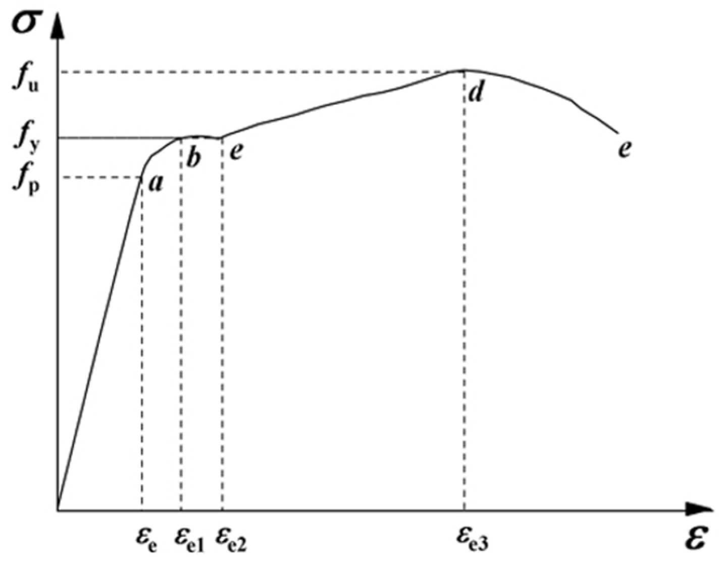
3.1. Material Constitutive Models
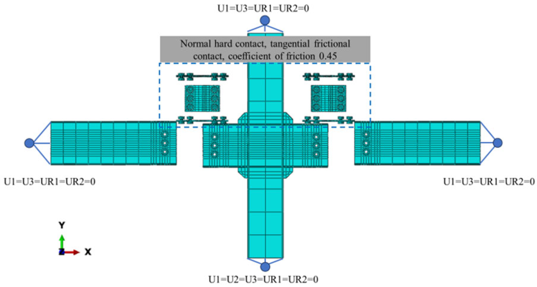
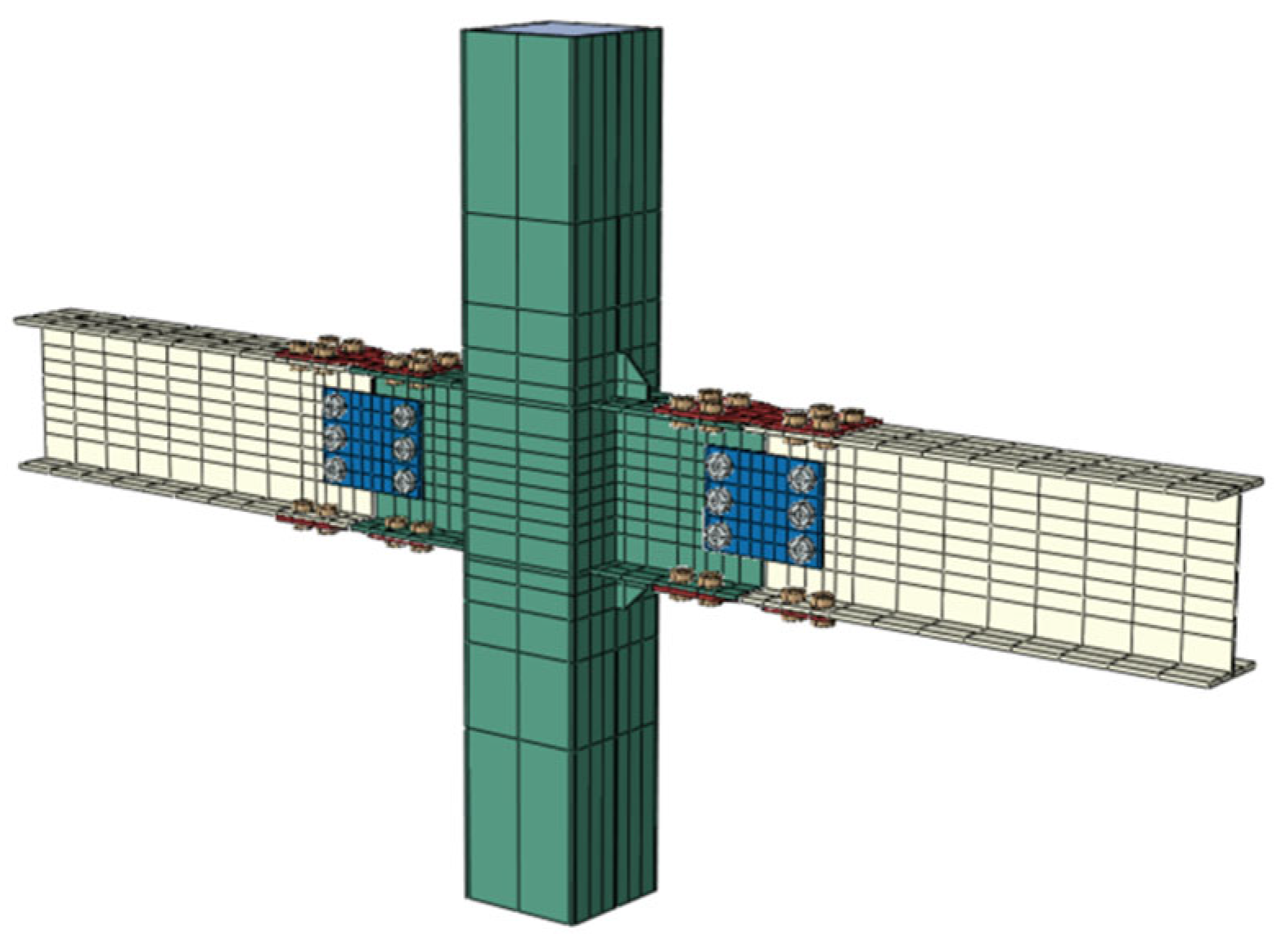
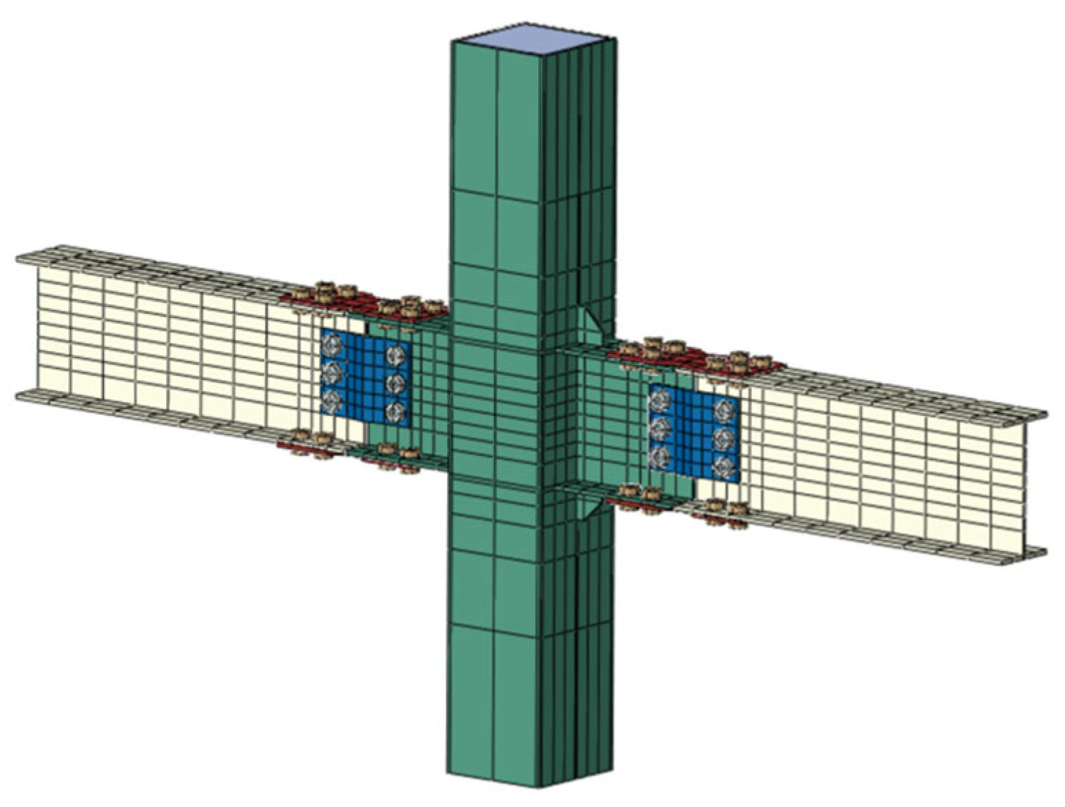
The elastic modulus of steel and high-strength bolts is taken as Es = 2.06 × 10⁵ N/mm2, and the Poisson’s ratio is 0.3. The constitutive relationship curve of high-strength bolts adopts the multi-linear isotropic strengthening model [30], as shown in Figure 4. The 10.9-grade high-strength bolts adopt the nominal value, f y = 980   M P a , and f u = 1100   M P a . According to the calculation, the stiffness reduction coefficient, k_1 = 0.0065, and its constitutive relationship is as shown in Equation (1):
σ s = E s ε s                                                                                       ε s ε y σ y + k 1 E s ε s ε y                               ε y ε s ε u σ u                                                                                               ε s ε u
ε y is the yield strain; σ u is the ultimate strength; ε u is the ultimate strain.
The constitutive model of ordinary steel adopts the constitutive model considering the platform section and the strengthening section proposed in reference [31], and the specific constitutive relationship is as shown in Figure 5.
σ = E ε ( ε ε e ) A ε 2 + B ε + C ( ε e ε ε e 1 ) f y ( ε e 1 ε ε e 2 ) f y 1 + 0.6 ε ε e 2 ε e 3 ε e 2 ( ε e 1 ε ε e 2 ) 1.6 f y ( ε > ε e 3 )
In the formula: the basic strain amount of the steel constitutive is ε e = 0.8   f y / E ; ε e = 1.5   ε e 1 ; ε e 2 = 100   ε e 1 ; ε e 3 = 100   ε e 1 ; the constant term of the expression in the plastic strengthening stage is A = ( 0.2 f y ε e 1 ε e ) 2 ; B = 2 A ε e 1 ; C = 0.8 f y + A ε e 2 B ε e , and the steel mechanical property data adopts the data suggested in reference [32].
The constitutive model of concrete adopts the concrete plastic damage (CPD) constitutive model, and the parameter settings of the plastic index are as follows: the dilation angle is taken as 38°, the eccentricity is taken as 0.1, the K value is taken as 0.66667, the ratio of the ultimate strength of biaxial compression to uniaxial compression f b 0 f c 0 is taken as 1.16, and the viscosity coefficient is taken as 0.00005.

3.2. Model Building

This study examines the model size parameters, all of which are presented in Table 1. It is noteworthy that uniform constitutive relationships are employed across all models. The primary modifications made to these models involve key design parameters, such as the strength and thickness of the V-shaped steel connectors, along with the size reduction and strength of the dog-bone sections.
Figure 6 provides a detailed depiction of the boundary conditions, mesh division, and contact relationships associated with the finite element model. The C3D8R solid element is used for the steel tube, concrete, V-shaped steel connector, dog-bone weakened connector, steel beam, and bolts. To mitigate the hourglass phenomenon that may occur during the deformation of reduced integral elements, an hourglass enhancement mode is implemented for each element. The interaction between the steel beam and the steel tube is modeled using a “tie” constraint. Additionally, surface-to-surface contact is employed to simulate the interaction between the steel tube and the concrete, the V-shaped steel connector, the dog-bone weakened connector, the steel beam, and the web members of the steel beam. “Hard contact” is specified for the normal direction, and the tangential direction utilizes the “Coulomb friction model”. The friction coefficient between the steel tube and the concrete is assigned to a value of 0.60, whereas all other friction coefficients are uniformly set at 0.35, Furthermore, automatic stabilization is activated to eliminate initial rigid body displacements. Following a comprehensive mesh sensitivity analysis, an optimized mesh scheme is adopted with refined zones of 15 mm and coarse zones of 30 mm. This dual-mesh strategy effectively balances computational accuracy and efficiency while capturing critical stress concentrations in key connection areas.
Due to the middle column joint being located at the beam-column inflection point in the frame, hinged boundary conditions are implemented at the upper and lower ends of the column and at the beam’s loading point. To mitigate out-of-plane instability of the joint surface, an additional out-of-plane constraint is applied within the core area of the joint, specifically setting U1 = U3 = UR1 = UR2 = 0. The top of the column and the ends on both sides are allowed degrees of freedom in the U2 and UR3 directions. Axial loading is applied at the top of the column, and reciprocating loading is applied at the beam’s terminal end.
The finite element model in this study has the following main limitations: A fixed friction coefficient (0.6 and 0.35) was adopted, without considering the influence of interface roughness variations on slip behavior; welded connections were assumed to be ideally rigid, neglecting residual stresses in the heat-affected zone and fatigue damage; the possible use of a simplified 2D model may underestimate local buckling and torsional effects in three-dimensional space; the material constitutive model does not fully account for the Bauschinger effect and anisotropy; quasi-static loading does not reflect the strain rate effects of actual seismic motions; the influence of construction and installation errors was not considered.

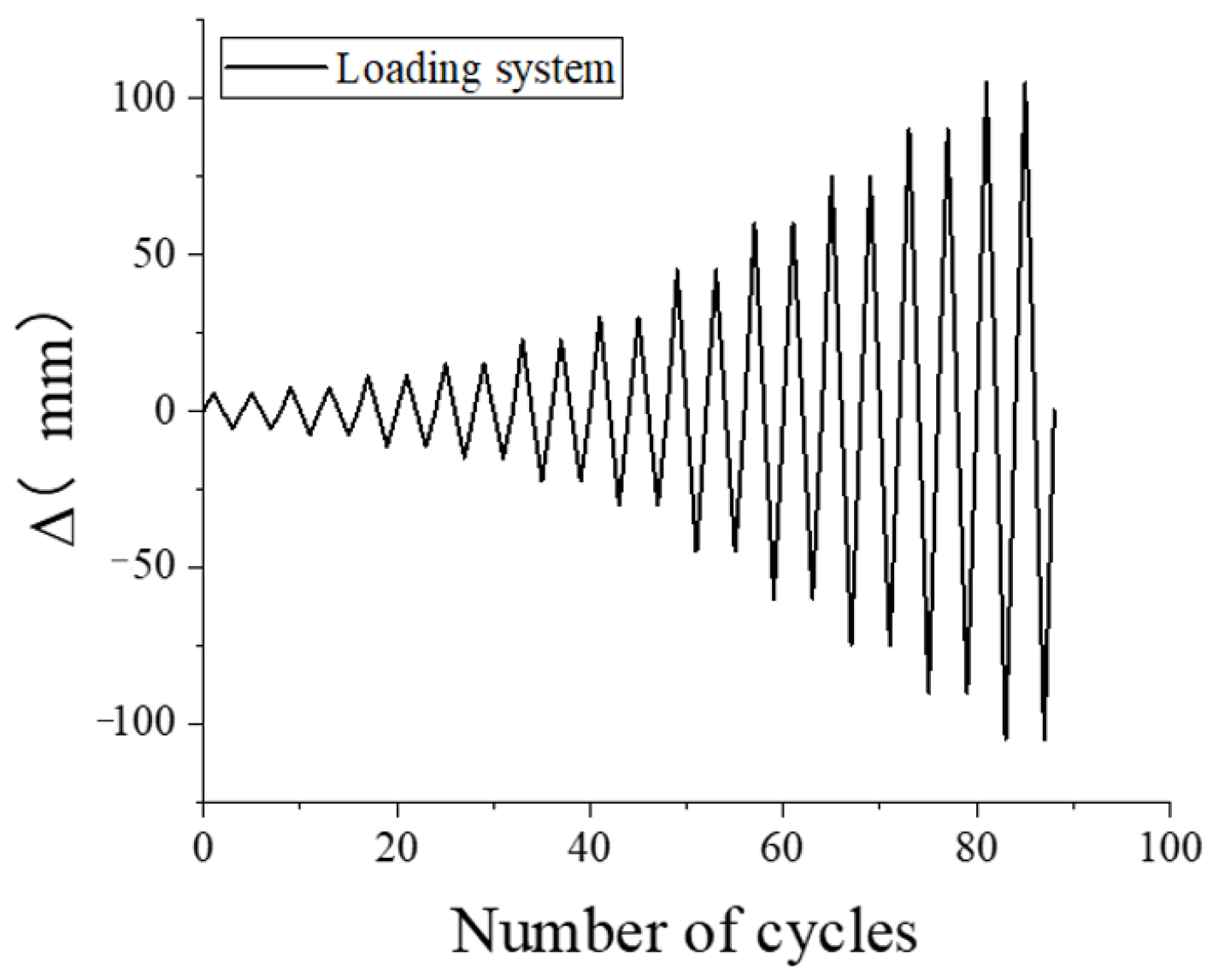
3.3. Loading Procedure

Axial force is induced at the top of the column through force application, with an axial compression ratio of 0.4. The member is subjected to loading at the beam end. The loading procedure is based on displacement loading, in accordance with the Code for Seismic Test of Buildings (JGJ/T101-2015) [33], and a detailed representation of the loading procedure is provided in Figure 7.

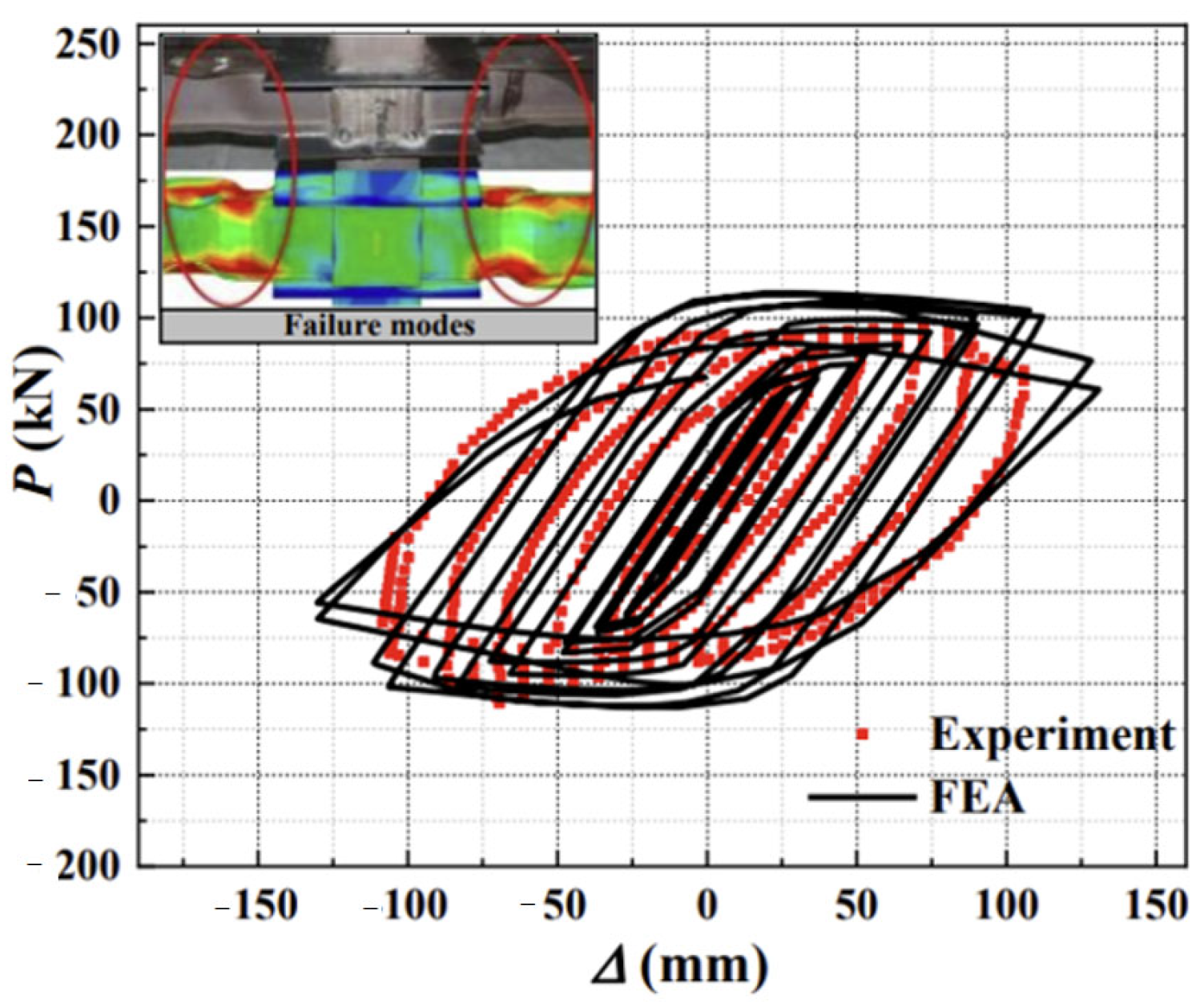
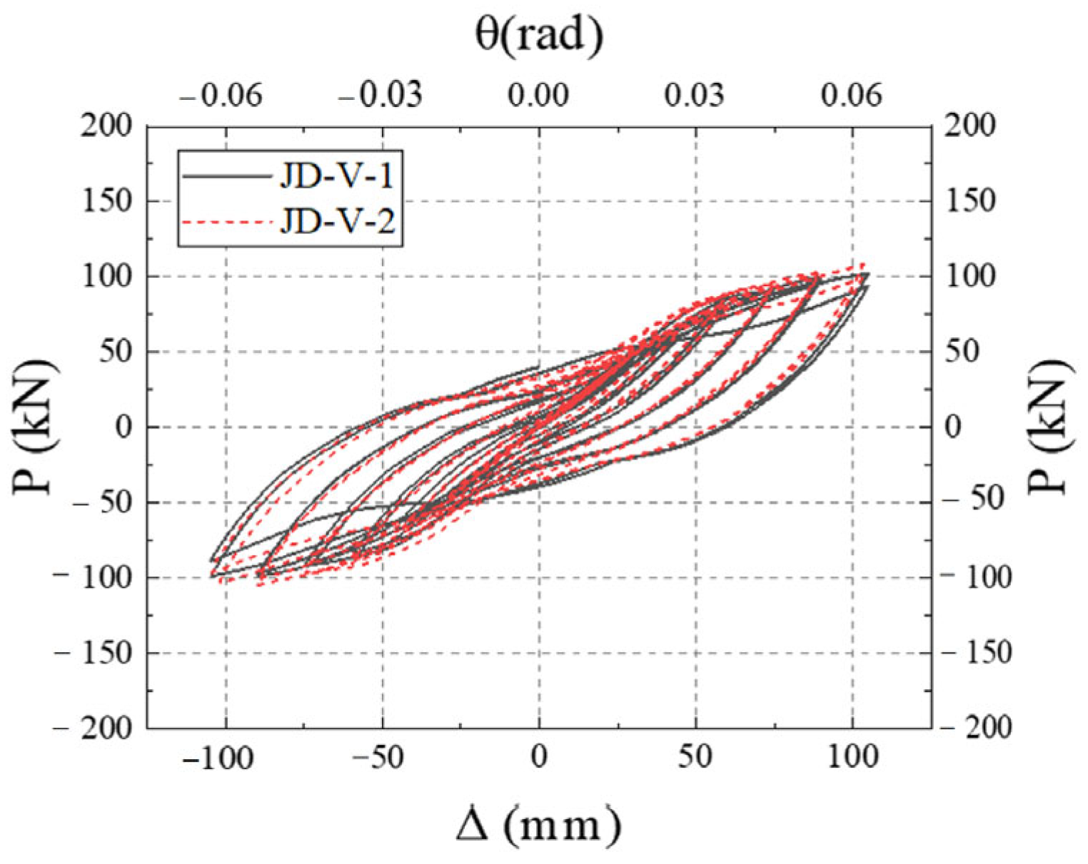
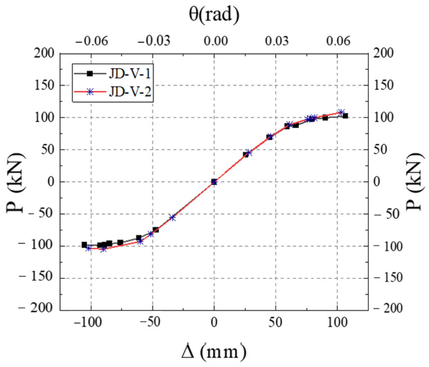
3.4. Finite Element Model Verification

To validate the accuracy of the finite element model, a comprehensive finite element simulation analysis is conducted on the experimental data presented in references [34,35]. Given the similarity between the test joints in the literature and the joint form addressed in this article, the verification model is set up with the same element selection, mesh division, and boundary conditions as outlined in Section 2.2, in order to ascertain the accuracy of the above-mentioned modeling method. Figure 8 provides a comparative analysis between the hysteretic curves derived from the experimental data in reference [34] and the corresponding finite element analysis results. Similarly, Figure 9 presents a comparative analysis between the skeleton curves obtained from the experiment in reference [35] and the associated finite element analysis.
As evidenced in Figure 8 and Figure 9, the finite element modeling approach developed in this study exhibits excellent agreement with experimental results for both hysteretic and skeleton curves. The simulated hysteresis loops in Figure 8 accurately reproduce the experimental energy dissipation characteristics, including pinching effects. Figure 9 demonstrates close alignment between numerical and experimental skeleton curves, with peak load deviations limited to +4.1% (positive loading) and −3.9% (negative loading). Comprehensive validation through error metrics shows RMSE below 10% and R2 exceeding 0.9. Furthermore, Monte Carlo analysis involving 100 samples of material properties and friction coefficients yields a low 3.8% variation in load-bearing capacity. These results collectively verify the reliability and robustness of the proposed finite element model for subsequent analytical investigations, with all observed discrepancies within acceptable engineering tolerances for seismic performance evaluation.

4. Finite Element Simulation Analysis

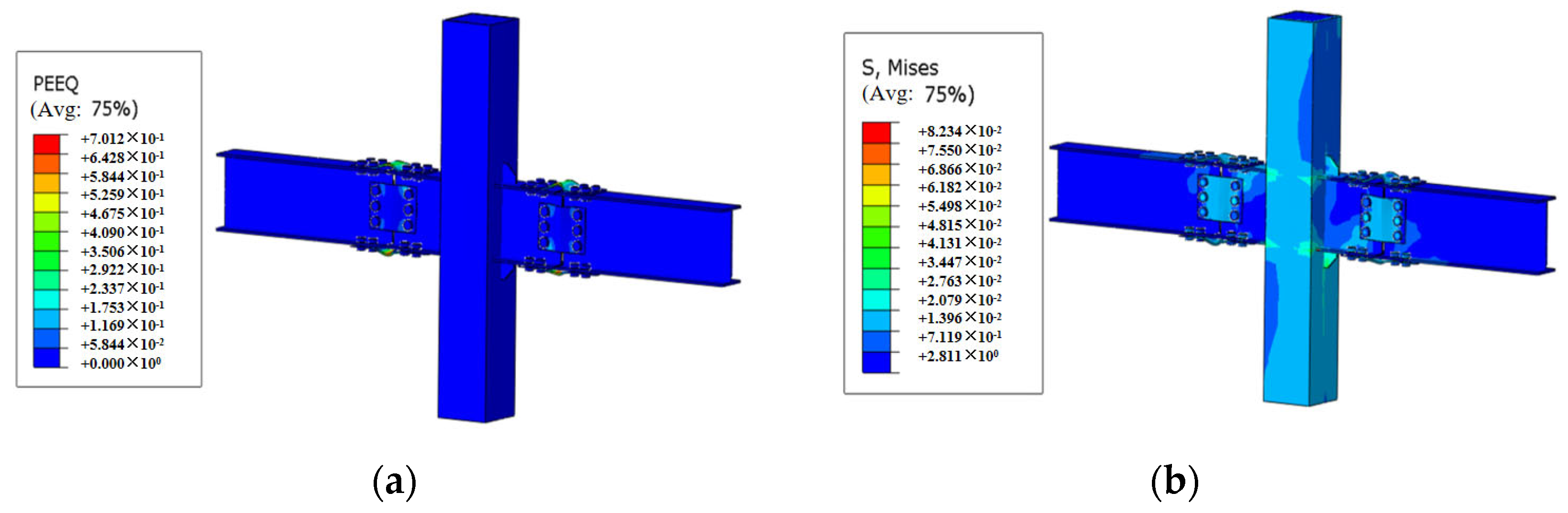
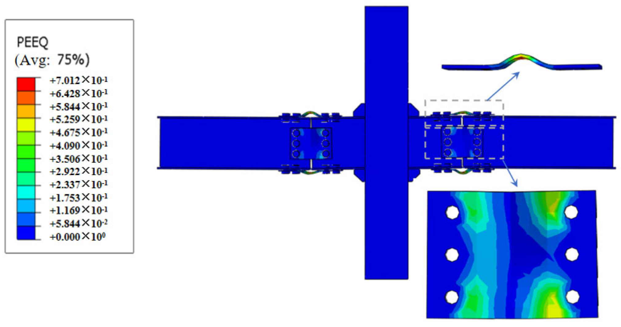
4.1. Analysis of Failure Mode of Typical Member

Figure 10 presents the distribution of equivalent plastic strain and Mises stress at a 4% inter-story drift angle of the typical member. Figure 10a indicates that the plastic hinge formation in the joint is predominantly concentrated at the sections of the dog-bone and V-shaped steel connectors. The V-shaped steel components form X-shaped shear bands during loading, which contribute more than 50% of the system’s total energy dissipation capacity. Simultaneously, the flange sections in the dog-bone weakened zones experience full cross-sectional yielding, demonstrating the effectiveness of the plastic hinge design. This dual energy-dissipation mechanism operates through a coordinated sequence: the V-shaped steel’s shear bands activate first to absorb the majority of energy, followed by progressive yielding of the dog-bone flanges as a secondary energy-absorbing mechanism. The formation of distinct X-pattern shear bands in the V-shaped steel components confirms the anticipated shear-dominated energy dissipation behavior, while the complete yielding of the dog-bone flanges verifies the proper functioning of the weakening design. Together, these complementary mechanisms provide a balanced and hierarchical energy dissipation system that effectively localizes damage while maintaining overall structural stability and performance, with other regions maintaining near-elastic conditions. The observed failure mode is section failure of the plastic hinge at the beam end. Figure 10b further highlights the presence of significant stress concentrations at the weakened portion of the dog-bone and the connection point of the V-shaped steel connector, suggesting that the introduction of an arc angle at this location could effectively reduce stress concentration. Moreover, this phenomenon underscores that the weakened configuration of the dog-bone and the structural dimensions of the V-shaped steel are pivotal in dictating the successful outward movement of the plastic hinge. Concurrently, these elements serve as key parameters that govern the failure mode.
Figure 11 illustrates the localized regions of plastic damage within the joint. The figure indicates that the damage is predominantly concentrated at the V-shaped steel connector and the dog-bone weakened connector, while the remaining portions of the structure remain in the elastic stage. This structural arrangement effectively aligns with the design objectives of damage containment and the post-earthquake replaceability of components.

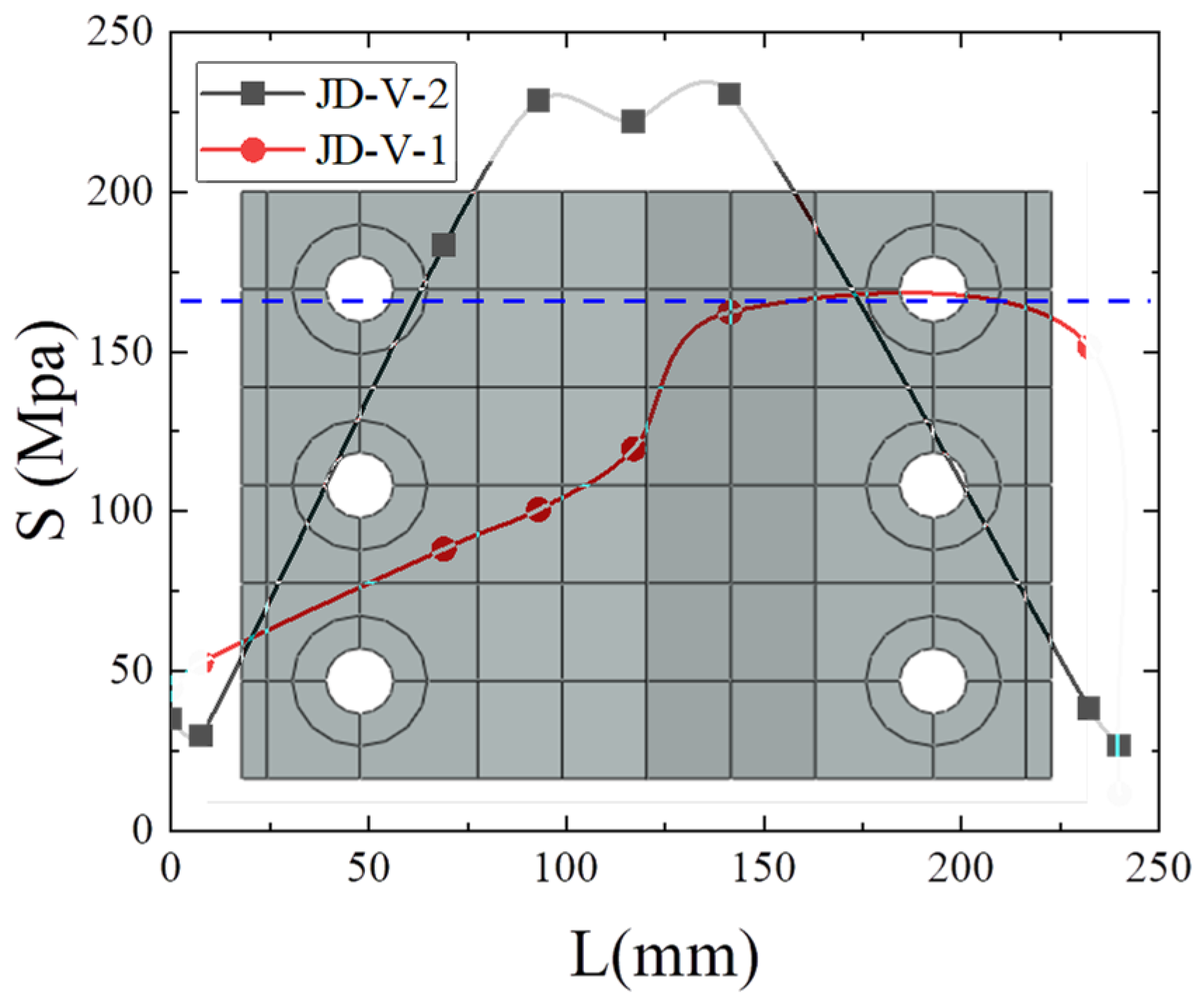
4.2. Stress Distribution

Subject to the reciprocating load of the beam, the primary mechanisms of force transfer to the joint area involve bending moments and vertical shear forces. These bending moments can be conceptualized as pairs of horizontal force couples acting on the upper and lower flanges of the beam. Consequently, in this section, an analysis is conducted by extracting the distributions of horizontal stress (S11) and vertical stress (S22) for each component in the joint area, based on the stress conditions at the joint.
Figure 12 presents the stress distribution across the connectors within the joint area. The figure reveals that the horizontal tensile and compressive stresses on the upper and lower flanges of the beam are conveyed to the bolt hole positions, subsequently transferred to the upper and lower dog-bone weakened connectors through the bolts, and further into the joint area via the dog-bone weakened connector. Similarly, the vertical shear stress of the beam’s web member is transmitted through the bolt holes to the V-shaped steel member, and finally into the column joint area through the cantilever beam section [36]. The clarity of the force transmission path underscores the importance of reasonable structural design in achieving a reliable force transfer. A summary of the distribution of the horizontal tensile and compressive stresses, as well as the vertical shear stresses, is depicted in Figure 13, outlining the force transmission path of this novel joint type.

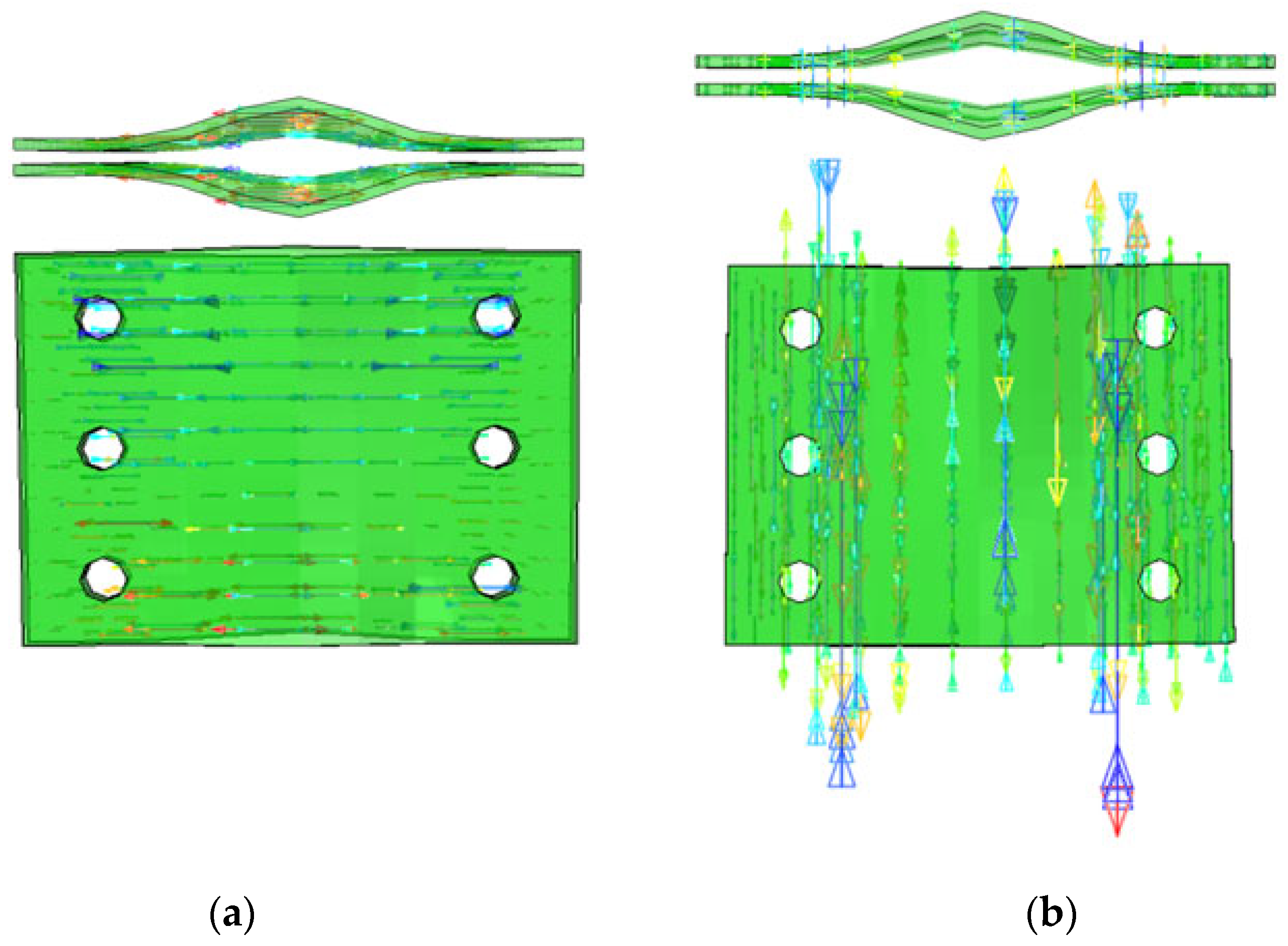
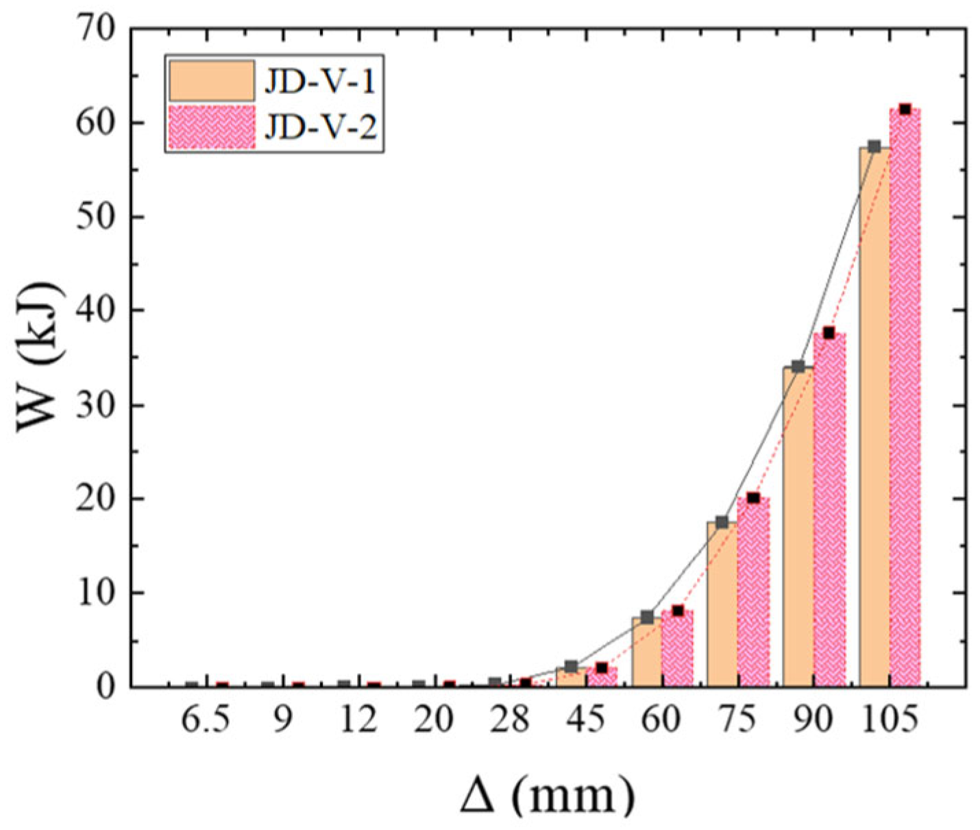
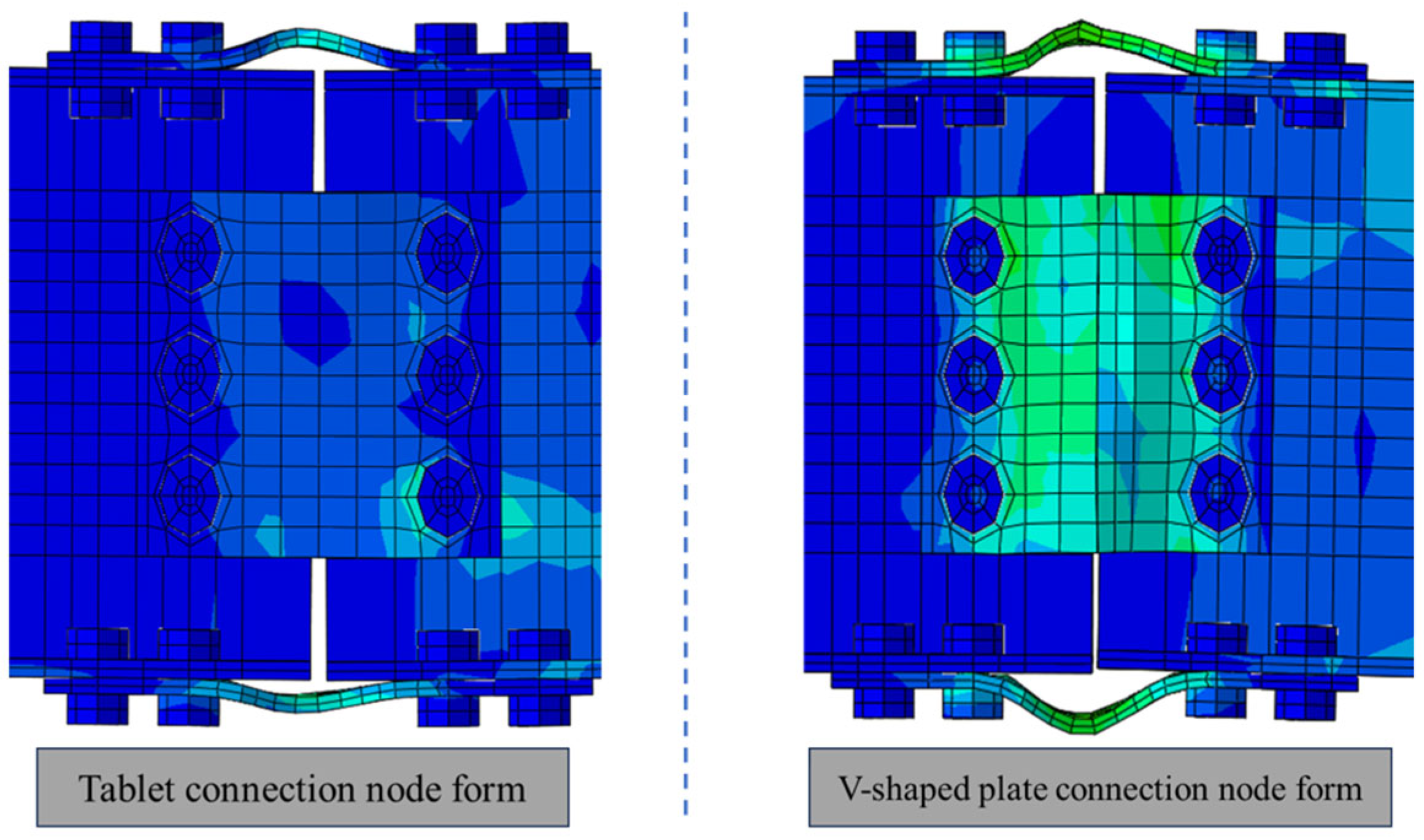
4.3. Comparative Analysis of Node Forms

A comparative analysis is undertaken to assess the mechanical properties of the JD-V-1 node configuration featuring a flat member energy dissipation connection, and the JD-V-2 joint configuration with a V-shaped steel connector for energy dissipation. Detailed schematic diagrams of the JD-V-1 and JD-V-2 joints are provided in Figure 14 and Figure 15.
The calculations for a novel beam-column connection joint, employing V-shaped steel as a replaceable component for energy dissipation, and the energy dissipation connection node utilizing a flat member are executed. The load-displacement curve derived from these calculations is depicted in Figure 16. Figure 16 illustrates the hysteretic curves for each member. The V-shaped steel connector in the JD-V-2 member demonstrates an opening and closing action under the reciprocating load at the beam end, manifesting as a distinct pinching effect in the hysteresis curve. This behavior results in a reduced fullness degree compared to the JD-V-1 member.
The equivalent viscous damping coefficients for members JD-V-1 and JD-V-2 are noted as 0.282 and 0.292, respectively, indicating a positive trend in enhancement. This indicates that the V-shaped steel connector effectively bolsters the energy dissipation capacity of the joint. The skeleton curve of the model is shown in Figure 17. The yield displacement Δ y is obtained on the skeleton curve by using the “energy equivalent method”, the peak load P m 85% is the failure load P u , and the corresponding displacement is the failure displacement Δ u . The average ductility coefficient μ is taken as the ratio of the failure displacement Δ u of the member to the yield displacement Δ y . Each characteristic point is the average of the positive and negative cycles.
Figure 18 and Figure 19 illustrate the viscous damping coefficient and stiffness degradation curves for members featuring various connection configurations. Member JD-V-2 demonstrates an initial stiffness enhancement of 1.7% relative to JD-V-1, with a corresponding increase in ultimate bearing capacity of 1.3%. The ductility coefficients for JD-V-1 and JD-V-2 are 3.32 and 3.62, respectively, and the cumulative energy dissipation capacity is augmented by 7.53%. To summarize, the mechanical performance of the joint configuration utilizing a V-shaped steel connector surpasses that with a flat member connector, and the ductility of the former is also more pronounced than that of the latter.
Figure 20 illustrates the stress distribution for the JD-V-1 and JD-V-2 members under a drift angle of 6% between stories. The figure demonstrates that the stress within the joint form utilizing a V-shaped steel connector is predominantly concentrated at the V-shaped steel member, whereas the stress within the joint form employing a flat member connector is comparatively low. Figure 21 offers a comparative analysis of the stress between the V-shaped steel connector and the flat member connector. The figure indicates that the stress value of the JD-V-2 member is elevated by 24.17% relative to the JD-V-1 member, and the V-shaped steel connector joint has transitioned into the plastic stage.

5. Parameter Analysis

The central factors impacting the mechanical performance of the innovative beam-column joint, which integrates V-shaped steel as a replaceable energy dissipation component without modifying the structural configuration, encompass the thickness and strength of the V-shaped steel connector, the strength, reduced dimension, and thickness of the dog-bone weakened connector, along with other relevant parameters. To comprehensively assess the mechanical performance of this novel joint, two groups of 14 models were designed, with each group featuring variations in the thickness and strength of the V-shaped steel connector, and in the strength, reduced dimension, and thickness of the dog-bone weakened connector. The specific parameters for each model are documented in Table 1.

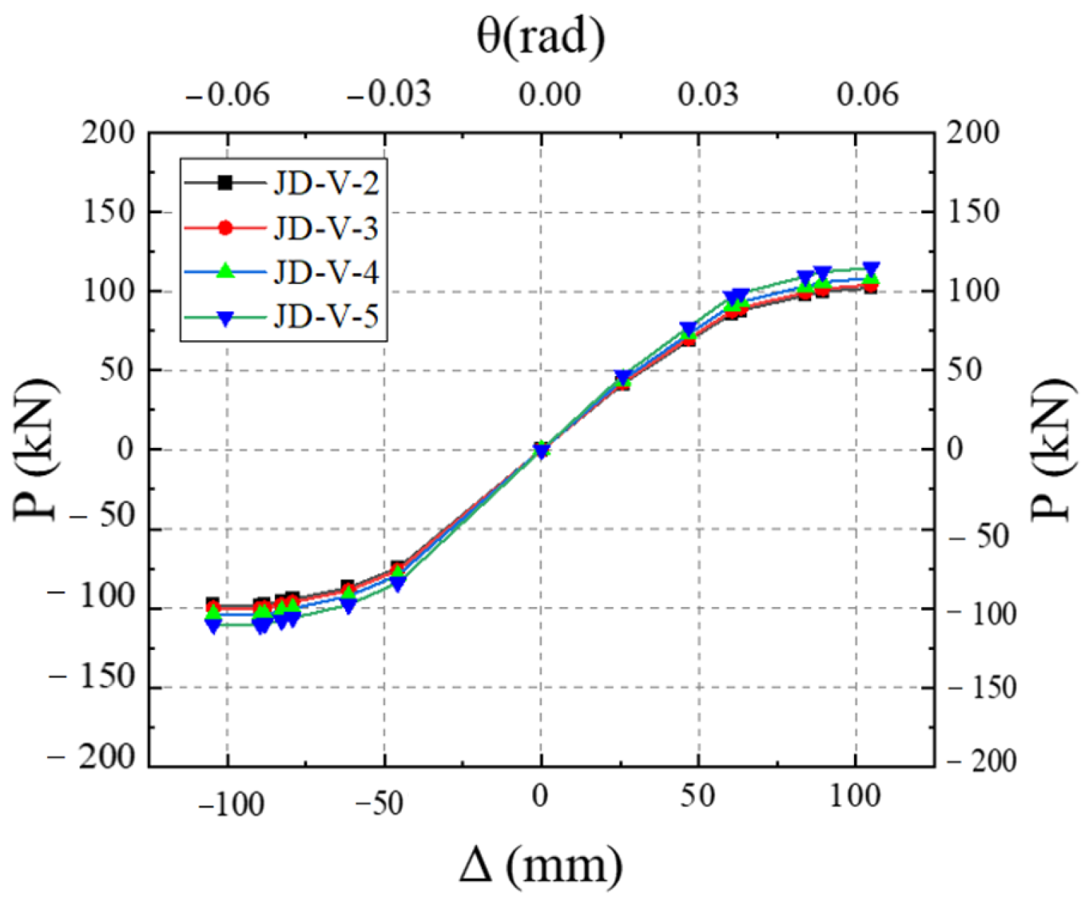
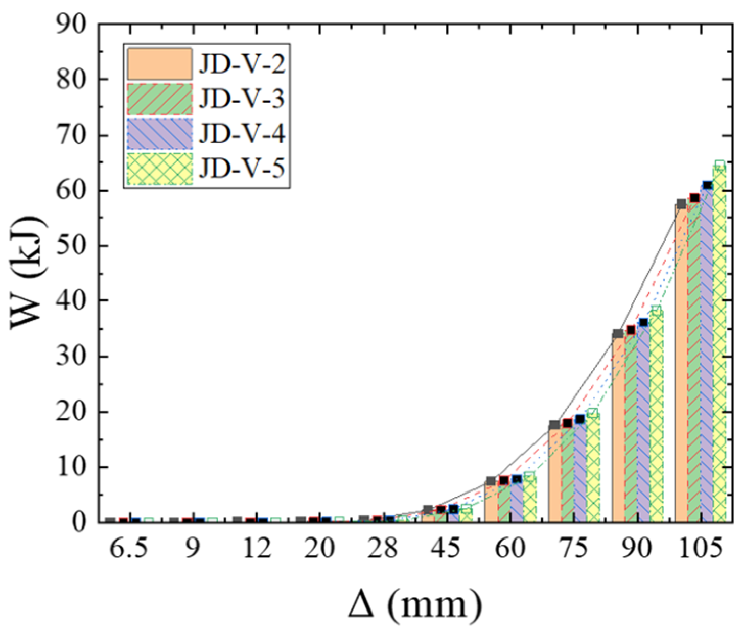
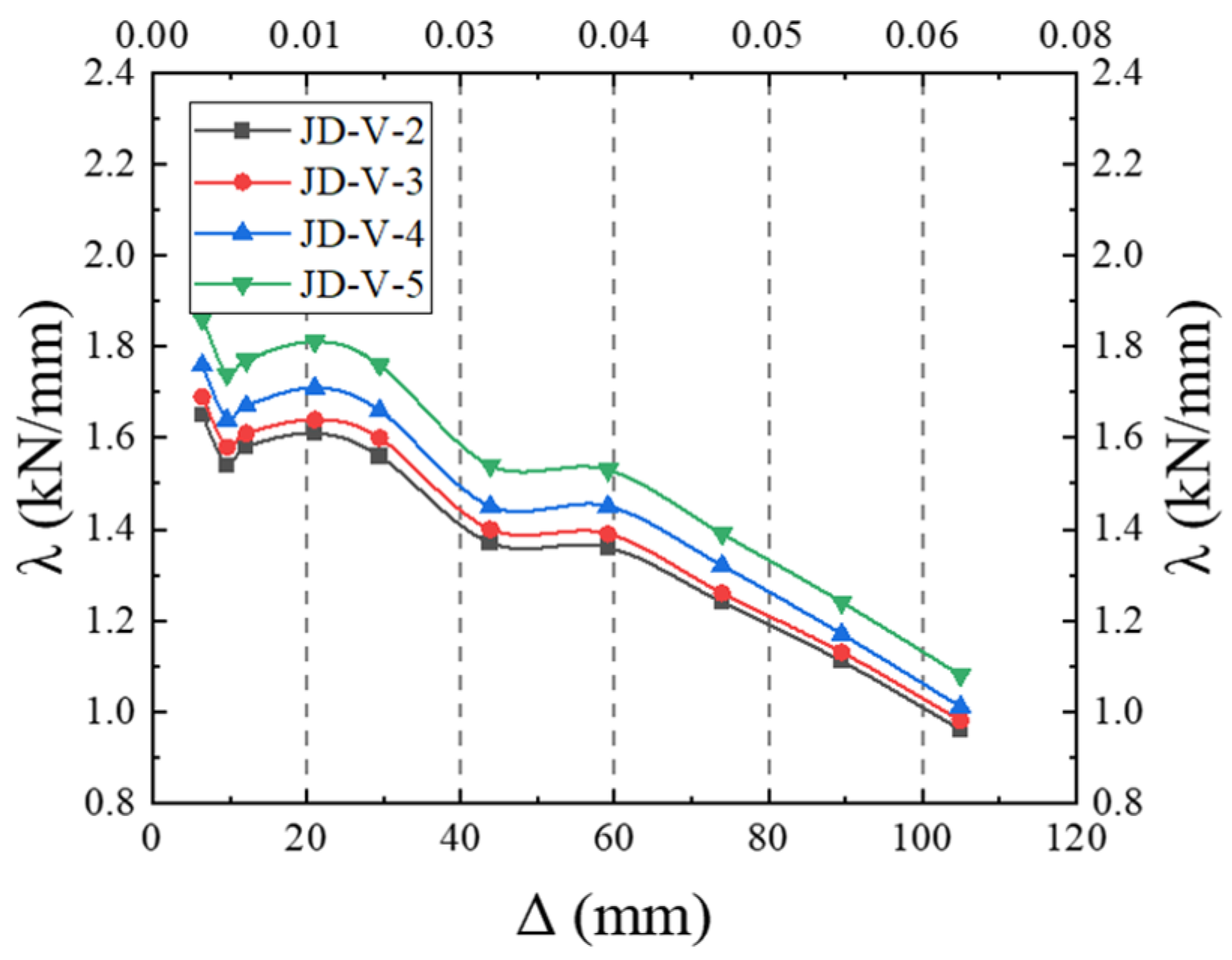
5.1. Effect of V-Shaped Steel Connector Thickness

The joint models with V-shaped steel connectors of varying thicknesses (2 mm, 3 mm, 4 mm, and 5 mm) were computationally analyzed, and their respective hysteretic curves are illustrated in Figure 22. The analysis reveals that an increase in the thickness of the V-shaped steel connector is associated with a greater degree of tension and compression deformation in the V-shaped steel. This trend results in a reduced fullness of the hysteretic curve and an elongation of the slip section, indicating a pronounced pinching effect.
The skeleton curves for the models are illustrated in Figure 23. Analysis of this figure reveals that the equivalent viscous damping coefficients for members JD-V-2, JD-V-3, JD-V-4, and JD-V-5 are 0.292, 0.287, 0.284, and 2.81, respectively, which demonstrate a declining trend. This indicates that an increase in the thickness of the V-shaped steel connector results in an enhancement of the energy dissipation section’s strength in the joint splice, which in turn leads to increased beam deformation and intensified bolt slippage, thereby diminishing the joint’s energy dissipation capacity.
Figure 24 and Figure 25 depict the cumulative energy-dissipating and stiffness degradation curves for members with differing thicknesses of the V-shaped steel connector. Analysis reveals that the initial stiffness of members JD-V-3, JD-V-4, and JD-V-5 has increased by 8.42%, 8.58%, and 9.30%, respectively, compared to JD-V-1, with the ultimate bearing capacity rising by 6.43%, 9.23%, and 10.64%, respectively. However, the ductility coefficients have decreased by 5.62%, 6.81%, and 7.12% respectively. In conclusion, the thickness of the V-shaped steel connector is directly proportional to the member strength. Considering the comprehensive performance metrics of the joint, a V-shaped steel connector thickness of 2–4 mm is recommended.

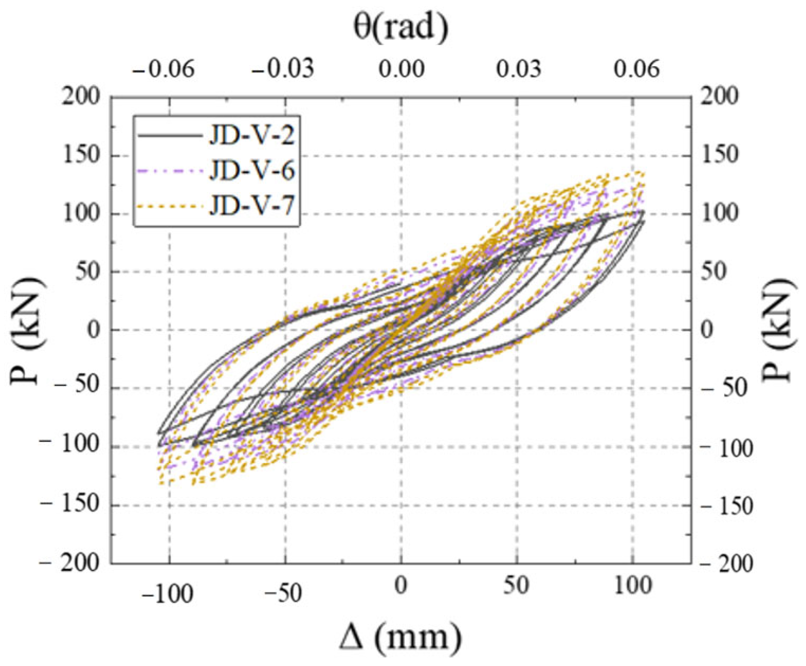
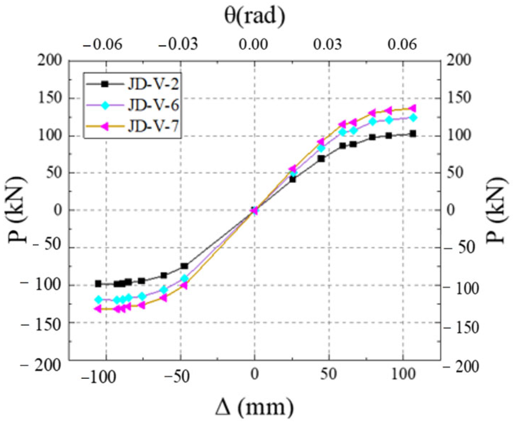
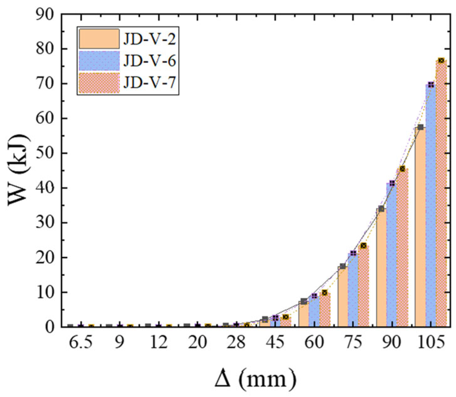
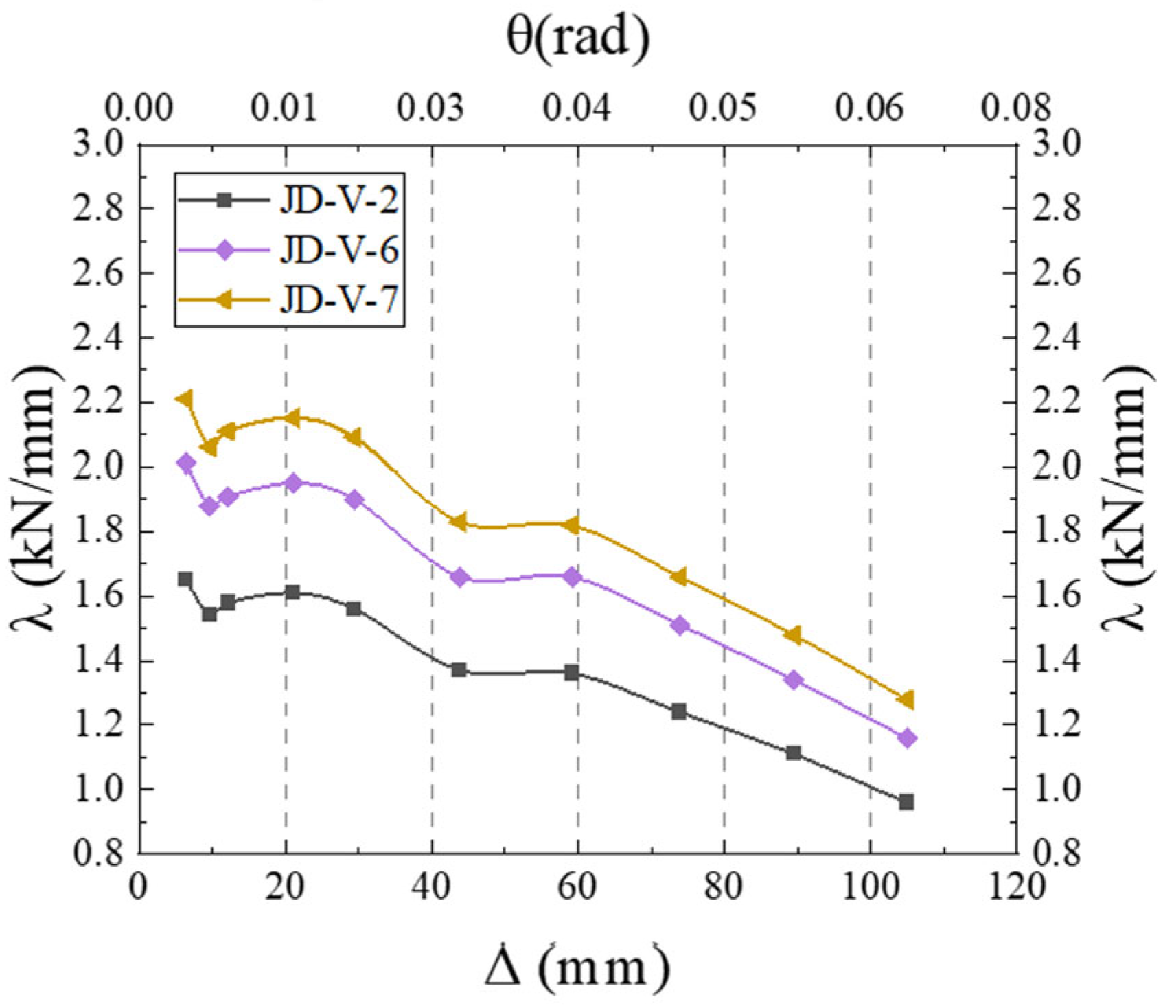
5.2. Effect of V-Shaped Steel Connector Strength

The models of the new type of joint, with V-shaped steel connectors having strengths of LY160, Q235, and Q355, were computationally analyzed, and the hysteretic curves obtained are depicted in Figure 26. Analysis indicates that, as the strength of the V-shaped steel connector increases, the fullness of the hysteretic curve also increases.
Figure 27 illustrates the skeleton curves for each member. Analysis of the equivalent viscous damping coefficients for members JD-V-2, JD-V-6, and JD-V-7, which are 0.292, 0.273, and 0.257, respectively, reveals a declining trend. This indicates that the increase in the strength of the V-shaped steel leads to an increase in the strength of the extended section of the joint, which in turn results in an inefficient plastic hinge migration effect and a decrease in the joint’s energy dissipation capacity.
Figure 28 and Figure 29 present the cumulative energy-dissipating diagrams and stiffness degradation curves for members with different strengths of the V-shaped steel connector. Analysis indicates that the initial stiffness of members JD-V6 and JD-V-7, when compared to JD-V-1, has increased by 12.25% and 19.12%, respectively, with the ultimate bearing capacity rising by 20.1% and 27.01%, respectively. However, the ductility coefficients have decreased by 5.7% and 8.6%, respectively. In conclusion, the strength of the member increases with the increase in the strength of the V-shaped steel connector. It is advised that the V-shaped steel connector should have a strength value corresponding to the LY160 grade.

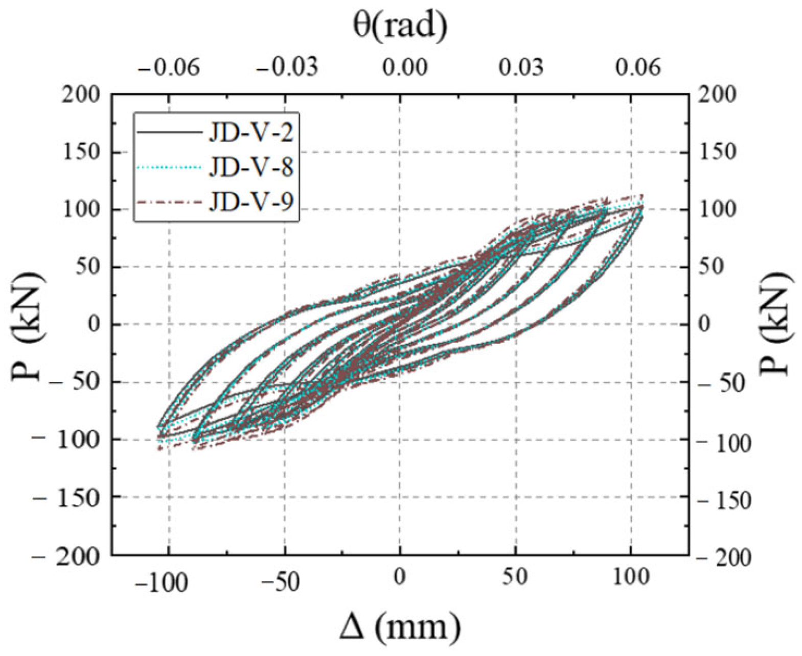
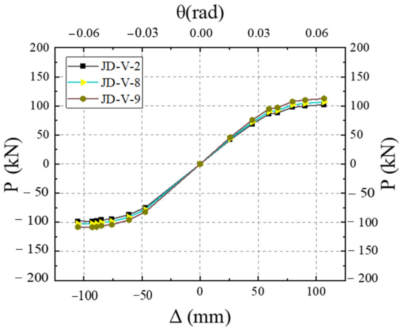
5.3. Effect of Weakening Size of Dog-Bone End

The models of the new joint type, featuring dog-bone weakening sizes of 15 mm, 20 mm, and 25 mm, were computationally analyzed, and their respective load-displacement curves are presented in Figure 30. The analysis reveals that an increase in the size of the dog-bone weakening results in an enhancement of the fullness of the hysteretic curve and an extension of the slip section.
Figure 31 presents the skeleton curves for each member. Analysis of the equivalent viscous damping coefficients, which are 0.292, 0.328, and 0.331 for members JD-V-1, JD-V-10, and JD-V-11, respectively, reveals an upward trend. This indicates that the increase in dog-bone weakening size results in a decrease in the strength of the beam end, which in turn leads to increased beam deformation and intensified bolt slip phenomena. The resulting ideal plastic hinge migration effect contributes to an enhanced energy dissipation capacity.
Figure 32 and Figure 33 illustrate the cumulative energy-dissipating and stiffness degradation curves for members with different sizes of dog-bone weakened connectors. The analysis reveals that the initial stiffness of members JD-V-10 and JD-V-11, relative to JD-V-1, has decreased by 7.78% and 9.40%, respectively, with a corresponding decrease in ultimate bearing capacity of 3.26% and 6.21%, respectively. Conversely, the ductility coefficients have increased by 6.81% and 8.13%, respectively. To summarize, the increase in the size of the dog-bone weakening results in an increase in the initial stiffness of the member. Based on a comprehensive evaluation of the mechanical and seismic performance characteristics of the joint, a reduced section dimension of 15–20 mm is recommended for the dog-bone connector.

5.4. Effect of Dog-Bone Weakened Connector Thickness

The joint models, featuring dog-bone weakened connection members with thicknesses of 6 mm, 8 mm, 10 mm, and 12 mm, were computationally analyzed, and the corresponding hysteretic curve is depicted in Figure 34. The analysis reveals that an increase in the thickness of the dog-bone weakened connection member leads to a lengthening of the slip section and a pronounced pinching effect.
Figure 35 illustrates the skeleton curves for each member. Analysis of the equivalent viscous damping coefficients, which are 0.292, 0.288, 0.271, and 0.268 for members JD-V-1, JD-V-10, JD-V-11, and JD-V-12, respectively, reveals a declining trend. This indicates that the increase in the thickness of the dog-bone weakened connector leads to an increase in the strength at the beam end, which in turn results in reduced beam deformation and an enhanced energy dissipation capacity.
Figure 36 and Figure 37 illustrate the cumulative energy-dissipating and stiffness degradation curves for members with different sizes of dog-bone weakened connector. The analysis reveals that the initial stiffness of members JD-V-10, JD-V-11, and JD-V-12, relative to JD-V-1, has increased by 7.78%, 9.40%, and 11.21%, respectively, with a corresponding increase in ultimate bearing capacity of 3.26%, 6.21%, and 10.15%, respectively. Conversely, the ductility coefficients have decreased by 4.21%, 6.81%, and 8.13%, respectively. To summarize, the increase in the thickness of the dog-bone weakened connection member results in an increase in the initial stiffness of the member. Considering the overall performance indicators of the joint, a thickness of 6–10 mm is recommended for the reduced section dog-bone connector.

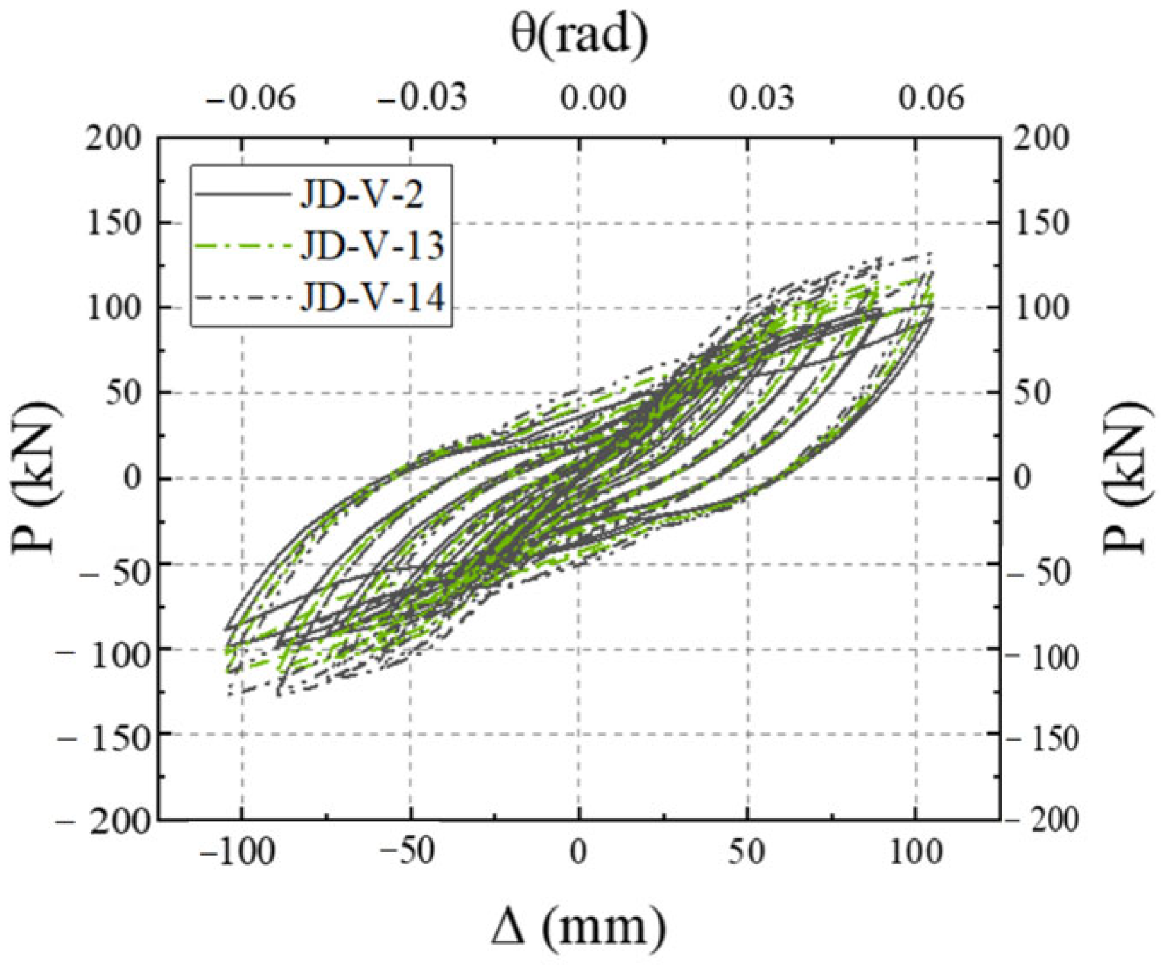
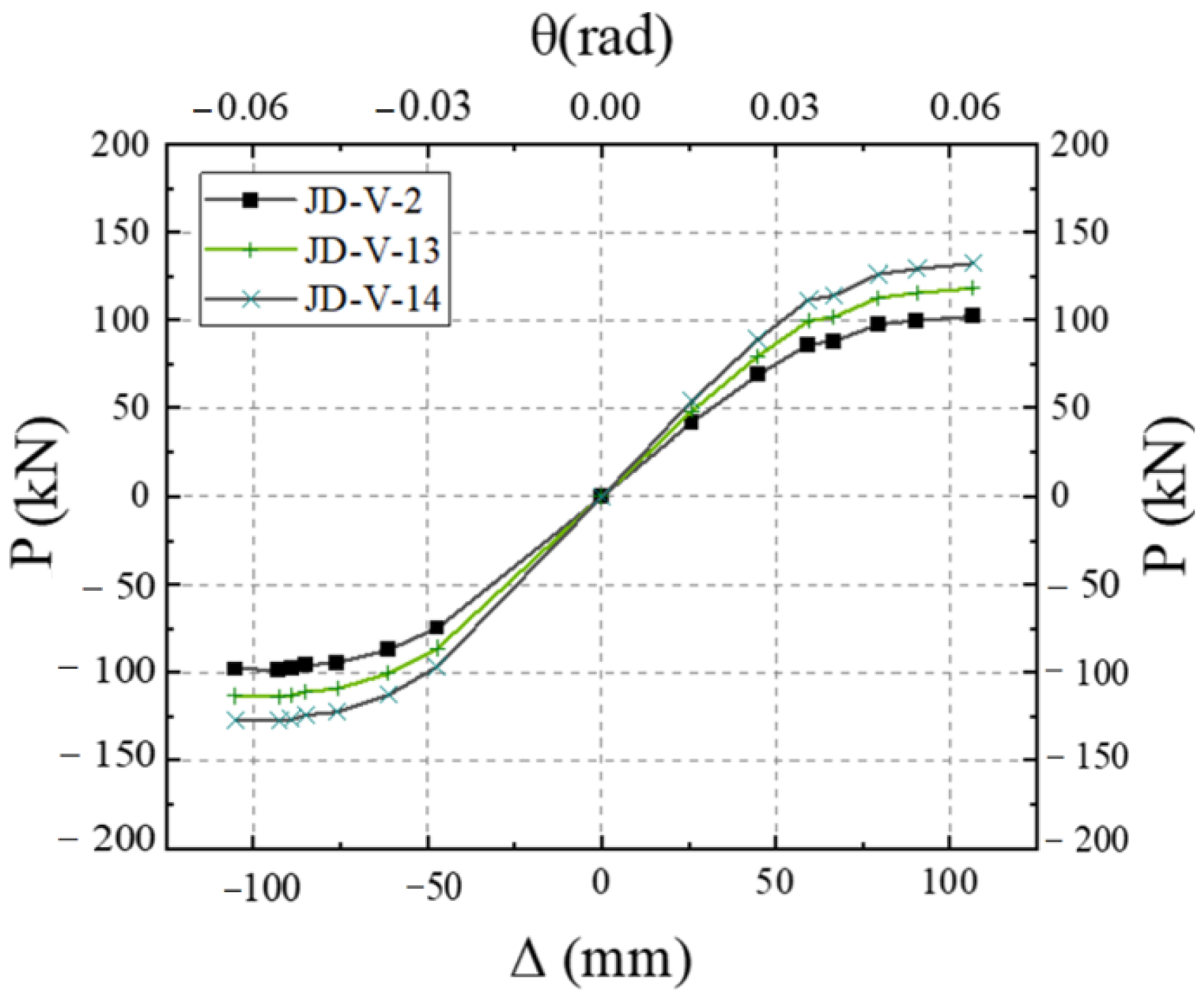
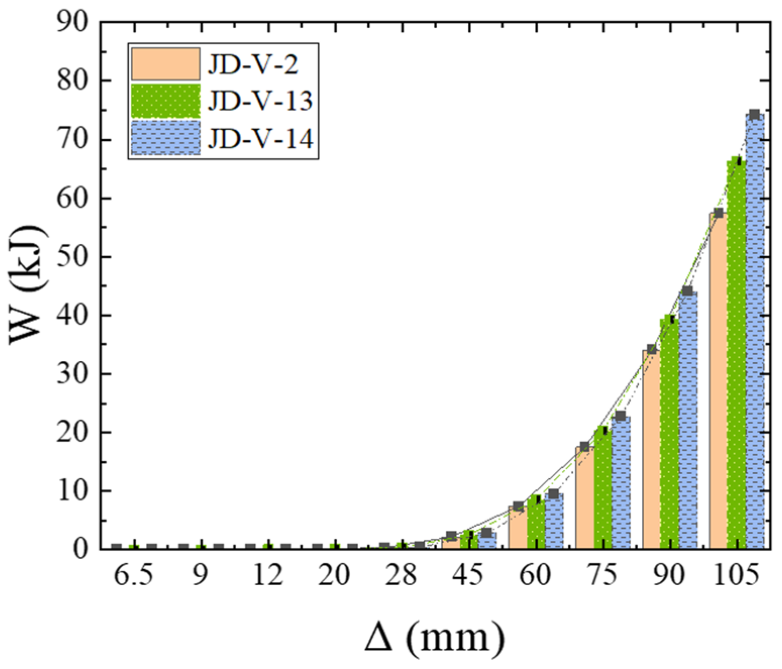
5.5. Effect of Dog-Bone Weakened Connector Strength

The models of the new type of joints, featuring weakened connectors of the dog-bone section with strengths of LY160, Q235, and Q355, respectively, were computationally analyzed, and the corresponding hysteretic curves are presented in Figure 38. Analysis indicates that an increase in the strength of the dog-bone connector results in a greater fullness of the hysteresis curve.
Figure 39 illustrates the skeleton curves for each member. Analysis of the equivalent viscous damping coefficients, which are 0.292, 0.287, and 0.276 for members JD-V-1, JD-V-13, and JD-V-14, respectively, reveals an upward trend. This indicates that the increase in the strength of the dog-bone leads to a weakened deformation capacity of the beam section, a poorer plastic hinge outward movement effect, and a reduction in energy dissipation capability.
Figure 40 and Figure 41 illustrate the cumulative energy-dissipating and stiffness degradation curves for members with different strengths of the dog-bone weakened connectors. Analysis reveals that the initial stiffness of members JD-V-13 and JD-V-14, relative to JD-V-1, is increased by 8.3% and 16.49% respectively, with the ultimate bearing capacity rising by 13.27% and 27.59% respectively. However, the ductility coefficients have decreased by 3.80% and 5.12%, respectively. To summarize, the increase in the strength of the dog-bone section connector results in an increase in the member strength. It is advisable that the strength of the dog-bone section connector is of the Q235 grade.

6. Discussion

This study first validates the numerical model through comparison with existing experimental results, followed by comprehensive mechanical performance analysis of the beam-column joint incorporating replaceable V-shaped steel energy-dissipating components. The analysis results indicate that replacing conventional flat steel plate connectors with V-shaped steel connectors leads to a comparable load-bearing capacity but a significant improvement in energy dissipation capacity. However, the energy dissipation capacity of the component decreases when the strength of the dog-bone weakened connector or the V-shaped connector increases. Similarly, an increase in connector strength also reduces the energy dissipation capacity, with the weakening effect gradually diminishing. When the weakening dimensions of the dog-bone weakened connector increase, the energy dissipation capacity improves, but the load-bearing capacity decreases. To maximize energy dissipation capacity while ensuring the load-bearing capacity of the component, the strength and thickness of the energy-dissipating connectors should be appropriately selected, and the weakening dimensions of the dog-bone weakened connector should not be excessively large.
Increasing the bolt friction coefficient reduces the pinching effect of the hysteresis curve, while a 1.5 mm bolt hole clearance diminishes ductility. This sensitivity analysis provides a theoretical basis for the reliability design of the joint, indicating that material nonlinearity and interface slippage are the dominant factors contributing to performance variability.
Due to the inherent limitations of numerical simulation in accounting for certain practical factors, our research team will conduct corresponding experimental studies in subsequent phases to enhance the practical significance of the research findings.
The V-shaped steel replaceable energy dissipation joint proposed in this research demonstrates remarkable advantages in engineering applications. The modular prefabrication and bolted connection design achieves 40% higher construction efficiency and 98% installation qualification rate. Post-earthquake replacement takes only 2 h, reducing maintenance time by 80% compared to conventional bracing systems. Life-cycle cost analysis indicates that, although the initial cost increases slightly, the 50-year total cost can be reduced through 70% lower post-earthquake repair costs and shorter functional recovery time, making it particularly suitable for buildings with high seismic resilience requirements in high-intensity zones such as schools and hospitals. This joint combines manufacturing simplicity, replacement convenience and long-term economic benefits, providing an optimized solution for prefabricated seismic-resistant structures.
To enhance the international applicability of the proposed joint system, three critical improvement measures are recommended: (1) implementing additional bolt slip resistance verification in accordance with AISC provisions, (2) incorporating prying effect checks following EN 1993-1-8 specifications, and (3) establishing ASTM/AISI material substitution protocols (e.g., A992 steel as an alternative to Q235). These adaptations will enable the technology to meet the seismic requirements of multi-code regions such as the Pacific Ring of Fire, while preserving its fundamental “strong joint–weak component” design philosophy.

7. Conclusions

This paper proposes a novel beam-column joint with replaceable V-shaped steel energy-dissipating components. Finite element simulations were conducted using ABAQUS to investigate the failure mechanism and load transfer path of the joint. Through parametric analysis, the influence of key design parameters on the seismic performance of the joint was examined, and constructive design recommendations were proposed. The main conclusions are as follows:
  • The novel joint achieves a synergistic design integrating dual energy-dissipation mechanisms and plastic hinge relocation through V-shaped steel connecting dampers, which complies with the seismic design principles of strong column–weak beam and strong joint–weak component. Moreover, it enables completely bolted on-site assembly connections.
  • Compared with joint configurations using flat plate connectors at the web, the joint with V-shaped steel connectors demonstrates superior energy dissipation capacity through flexural deformation of the V-shaped components during the elastoplastic stage, exhibiting more stable and fuller hysteresis loops. The failure mode concentrates on the dog-bone weakened connections and plastic hinge formation in the beam sections at V-shaped connectors, while the joint core zone maintains elastic column sections without significant concrete damage. This configuration achieves the seismic performance objectives of controllable damage and post-earthquake replaceability, while ensuring reliable and well-defined force transfer paths.
  • The beam-column joint equipped with V-shaped replaceable energy-dissipating components demonstrates superior performance compared to conventional flat plate connection joints, exhibiting a 1.7% increase in initial stiffness and a 1.3% enhancement in ultimate load-bearing capacity. More significantly, the proposed configuration achieves a 9% improvement in ductility and a 7.53% increase in cumulative energy dissipation capacity. These results confirm that the innovative design effectively enhances both the ductile behavior and energy dissipation capability of the joint, while maintaining its fundamental stiffness and load-bearing characteristics.
  • The strength and dimensions of both the V-shaped steel connectors and dog-bone weakened connections were identified as critical parameters affecting the joint’s seismic performance. Based on comprehensive analysis, the recommended specifications are that V-shaped connectors should adopt LY160 steel with a thickness of 2–4 mm, while dog-bone weakened connections should use Q235 steel with a thickness of 6–10 mm and a weakened zone dimension of 15–20 mm. However, practical applications face three major challenges: stringent construction accuracy requirements, insufficient environmental durability, and relatively high initial costs. These limitations will be systematically addressed through further research and experimental optimization in subsequent studies.

Author Contributions

Conceptualization, L.Z. and Y.H.; methodology, L.Z.; software, L.Z.; validation, Y.W., Y.H. and L.Z.; formal analysis, Y.H.; investigation, Y.W.; resources, Y.W.; data curation, Y.W.; writing—original draft preparation, L.Z.; writing—review and editing, Y.H.; visualization, Y.H.; supervision, Y.W.; project administration, Y.W., Y.H. and L.Z.; funding acquisition, Y.W. All authors have read and agreed to the published version of the manuscript.

Funding

This research was funded by the Natural Science Foundation of Hebei Province, China (Funding No. G2023502005), and the Fundamental Research Funds for the Central Universities (Funding No. 2025MS170).

Data Availability Statement

The data presented in this study is available on request from the corresponding author. The data is not publicly available due to privacy.

Acknowledgments

We acknowledge three authors in this study.

Conflicts of Interest

The authors declare no conflicts of interest.

References

  1. Chen, Y.; Chen, W.; Hao, H.; Xia, Y. Damage evaluation of a welded beam–column joint with surface imperfections subjected to impact loads. Eng. Struct. 2022, 261, 114276. [Google Scholar] [CrossRef]
  2. Nelson, N.R.; Prasad, N.S.; Sekhar, A. Structural integrity and sealing behavior of bolted flange joint: A state of art review. Int. J. Press. Vessel. Pip. 2023, 204, 104975. [Google Scholar] [CrossRef]
  3. Hou, N.; Ding, N.; Qu, S.; Guo, W.; Liu, L.; Xu, N.; Tian, L.; Xu, H.; Chen, X.; Zaïri, F.; et al. Failure modes, mechanisms and causes of shafts in mechanical equipment. Eng. Fail. Anal. 2022, 136, 106216. [Google Scholar] [CrossRef]
  4. Popov, E.P.; Bertero, V.V. Cyclic Loading of Steel Beams and Connections. J. Struct. Div. 1973, 99, 1189–1204. [Google Scholar] [CrossRef]
  5. Shen, J.; Kitjasateanphun, T.; Srivanich, W. Seismic performance of steel moment frames with reduced beam sections. Eng. Struct. 2000, 22, 968–983. [Google Scholar] [CrossRef]
  6. Chen, S.-J.; Yeh, C.H.; Chu, J.M. Ductile Steel Beam-to-Column Connections for Seismic Resistance. J. Struct. Eng. 1996, 122, 1292–1299. [Google Scholar] [CrossRef]
  7. Zhang, J.; Cui, Y.; Zhang, T. A novel damage-control PC beam-column joint with fully precast slab: Experimental investigation. J. Build. Eng. 2025, 106, 112513. [Google Scholar] [CrossRef]
  8. Zhang, J.; Tang, L.; Liu, W.; Zhang, M. Seismic performance of earthquake-damaged HSRAC beam-column interior joints rehabilitated by bonding steel plates in the plastic hinge of beams. Structures 2024, 69, 107357. [Google Scholar] [CrossRef]
  9. Du, Y.; Li, F.; Li, H.; Hong, N.; Chi, P. Seismic behavior and resilience assessment of prefabricated beam–column joint with replaceable graded-yielding energy-dissipating connectors. Eng. Struct. 2024, 319, 118814. [Google Scholar] [CrossRef]
  10. Chen, L.; Wang, Z.; Ma, B.; Peng, G.; Wang, C.; Zhou, L. Seismic performance of a novel steel-concrete composite beam-column joint. J. Constr. Steel Res. 2025, 229, 109479. [Google Scholar] [CrossRef]
  11. Jafari, A.; Shahmansouri, A.A.; Pourshamsian, S.; Bengar, H.A.; Zhou, Y. Post-tensioned coupling beams: Mechanics, cyclic response, and damage evaluation. Soil Dyn. Earthq. Eng. 2025, 188, 109082. [Google Scholar] [CrossRef]
  12. Chen, P.; Pan, J.; Hu, F.; Wang, Z. Experimental investigation on earthquake-resilient steel beam-to-column joints with replaceable buckling-restrained fuses. J. Constr. Steel Res. 2022, 196, 107413. [Google Scholar] [CrossRef]
  13. Yu, J.; Peng, J.; Wang, Y.H.; Luo, W.W.; Li, C.Y.; Wang, L.P. Study on seismic performance of steel frame beam-slab-column joint based on angle unilateral connection. Eng. Struct. 2025, 330, 119888. [Google Scholar] [CrossRef]
  14. Li, G.; Qin, Z.; Li, X.; Liu, M. Numerical study on the seismic performance of H-beam to built-in CFRP circular tube CFST column joint with replaceable energy dissipation angle steel. Structures 2024, 67, 106793. [Google Scholar] [CrossRef]
  15. Men, J.; Li, T.; Zhou, Q.; Zhang, H.; Huang, C.H. Structural fuse performance and earthquake-resilient performance of beam-column joints with replaceable T-stub. J. Constr. Steel Res. 2023, 206, 107943. [Google Scholar] [CrossRef]
  16. Cui, W.B.; Liu, X.C.; Chen, X.; Guo, L.X. Seismic performance of bolted beam-to-column composite joints with integrated precast edge composite hollow floor slab. J. Build. Eng. 2025, 105, 112438. [Google Scholar] [CrossRef]
  17. Feng, Y.; Han, C.; Chen, W. Theoretical, experimental and numerical studies of a novel tension-compression bolt (TCB) for single-sided beam-column joints. Thin-Walled Struct. 2025, 212, 113172. [Google Scholar] [CrossRef]
  18. Zhang, C.; Hu, S.; An, R.; Wang, Z. Seismic performance of a newly assembled joint between shaped steel beams and square steel tubular columns. J. Build. Eng. 2025, 100, 111748. [Google Scholar] [CrossRef]
  19. Yi, W.; Zhu, L.; Wang, Z.; Sun, H.; Yin, F. Experimental and numerical study on seismic performance of H-beam to HSST column joints connected by elliptical head one-sided bolts. J. Build. Eng. 2025, 102, 111855. [Google Scholar] [CrossRef]
  20. Hou, G.; Shang, Y.; Zhang, L.; Sun, L.; Wu, J.; Lu, Y.; Zhu, A.; Mou, Y. Bending performance of bolted beam-column joints with T-stubs. J. Constr. Steel Res. 2025, 226, 109280. [Google Scholar] [CrossRef]
  21. Wang, Y.; Zhang, D.; Zhao, J.; Du, Q.; Chen, H. Seismic performance of CFDST column to steel beam welded-bolted joint with slab. J. Constr. Steel Res. 2025, 226, 109192. [Google Scholar] [CrossRef]
  22. Wang, Y.; Zhang, D.; Zhao, J.; Du, Q.; Bwalya, J. Experimental and numerical investigation on ring-plate CFDST column to steel beam bolted-welded joint. Structures 2024, 69, 107586. [Google Scholar] [CrossRef]
  23. Rasoulitabar, M.; TahamoliRoudsari, M.; Memarzadeh, P.; Fathi, F. Experimental investigation of the cyclic behavior of bolted T-stub steel connections. Steel Compos. Struct. 2025, 55, 397. [Google Scholar] [CrossRef]
  24. Yin, L.; Zhu, Y.; Cai, X.; Xu, Z.; Zhang, J. Seismic performance of self-centering precast concrete buckling-restrained braced frame sub-assembly. J. Build. Eng. 2025, 107, 112690. [Google Scholar] [CrossRef]
  25. Xiong, S.; Yang, N.; Guan, H.; Shi, G.; Luo, M.; Deguchi, Y.; Cui, M. Combination of plasma acoustic emission signal and laser-induced breakdown spectroscopy for accurate classification of steel. Anal. Chim. Acta 2025, 1336, 343496. [Google Scholar] [CrossRef] [PubMed]
  26. Li, D.; Nie, J.-H.; Wang, H.; Yu, T.; Kuang, K.S.C. Path planning and topology-aided acoustic emission damage localization in high-strength bolt connections of bridges. Eng. Struct. 2025, 332, 120103. [Google Scholar] [CrossRef]
  27. Tang, H.; Peng, J.; Peng, H.; Yang, Y.; Gao, Q.; Xiao, L.; Li, H.; Zheng, L.; Chen, Z.; Yang, Z. Test and Theoretical Investigations on Flexural Behavior of High-Performance H-Shaped Steel Beam with Local Corrosion in Pure Bending Zone. Steel Res. Int. 2025, 96, 2400640. [Google Scholar] [CrossRef]
  28. GB50011-2010; Seismic Design Code of Building. China Building Industry Press: Beijing, China, 2016. (In Chinese)
  29. GB50017-2017; Steel Structure Design Standard. China Building Industry Press: Beijing, China, 2017. (In Chinese)
  30. Nagesh; Gupta, N.K. Response simulations of clamped circular steel plates under uniform impulse and effects of axisymmetric stiffener configurations. Int. J. Impact Eng. 2022, 159, 104049. [Google Scholar] [CrossRef]
  31. Zhou, J.; Ren, J.; Feng, Y.; Tian, W.; Shi, K. A modified parallel-sided shear zone model for determining material constitutive law. Int. J. Adv. Manuf. Technol. 2017, 91, 589–603. [Google Scholar] [CrossRef]
  32. Feng, Y.; Li, W. Seismic performance of SMA-prestressed self-centering beam-column joints: Experimental and numerical study. J. Constr. Steel Res. 2025, 226, 109272. [Google Scholar] [CrossRef]
  33. JGJ/T101-2015; Code for Seismic Test of Buildings. China Building Industry Press: Beijing, China, 2015. (In Chinese)
  34. Zuo, B. Pseudo-Static Experimental Study of H-Shaped Beams to Cold-Formed Square Steel Tube Columns Connections with Different Outer Diaphragm. Master’s Thesis, Qingdao Technological University, Qingdao, China, 2014. (In Chinese). [Google Scholar]
  35. Yuan, Z.R. The Research on the Mechanical Performance of the Square Concrete Filled Steel Tube with T-Stub Connector. Master’s Thesis, Hunan University, Changsha, China, 2013. (In Chinese). [Google Scholar]
  36. Sarfarazi, S.; Saffari, H.; Fakhraddini, A. Shear behavior of panel zone considering axial force for flanged cruciform Columns. Civ. Eng. Infrastruct. J. 2020, 53, 359–377. [Google Scholar] [CrossRef]
Figure 1. Joint composition and installation flow.
Buildings 15 02513 g001
Figure 2. Design principles.
Buildings 15 02513 g002
Figure 3. Detailed dimensions of each component.
Buildings 15 02513 g003
Figure 4. High strength bolts constitutive models.
Buildings 15 02513 g004
Figure 5. Ordinary steel constitutive model.
Buildings 15 02513 g005
Figure 6. Model meshing and boundary conditions.
Buildings 15 02513 g006
Figure 7. Loading system diagram.
Buildings 15 02513 g007
Figure 8. The results of hysteresis loops.
Buildings 15 02513 g008
Figure 9. The results of skeleton curves.
Buildings 15 02513 g009
Figure 10. Failure mode diagram of typical members. (a) PEEQ. (b) Von Mises.
Buildings 15 02513 g010
Figure 11. Plastic damage concentration area of typical member.
Buildings 15 02513 g011
Figure 12. Stress distribution of connectors in nodal domain. (a) Distribution of horizontal stress S11. (b) Vertical stress S22 distribution.
Buildings 15 02513 g012
Figure 13. Schematic of force transmission path.
Buildings 15 02513 g013
Figure 14. Flat plate as energy-dissipating component.
Buildings 15 02513 g014
Figure 15. V-shaped steel as energy-dissipating component.
Buildings 15 02513 g015
Figure 16. Hysteretic curves.
Buildings 15 02513 g016
Figure 17. Skeleton curves.
Buildings 15 02513 g017
Figure 18. Cumulative energy-dissipating curves.
Buildings 15 02513 g018
Figure 19. Stiffness degradation.
Buildings 15 02513 g019
Figure 20. Stress of joints under 6% inter-story drift angle.
Buildings 15 02513 g020
Figure 21. Comparative analysis of stress of V-shaped steel and flat connector.
Buildings 15 02513 g021
Figure 22. Hysteretic curves.
Buildings 15 02513 g022
Figure 23. Skeleton curves.
Buildings 15 02513 g023
Figure 24. Cumulative energy-dissipating curves.
Buildings 15 02513 g024
Figure 25. Stiffness degradation.
Buildings 15 02513 g025
Figure 26. Hysteresis curves.
Buildings 15 02513 g026
Figure 27. Skeleton curves.
Buildings 15 02513 g027
Figure 28. Cumulative energy-dissipating curves.
Buildings 15 02513 g028
Figure 29. Stiffness degradation curves.
Buildings 15 02513 g029
Figure 30. Hysteretic curves.
Buildings 15 02513 g030
Figure 31. Skeleton curves.
Buildings 15 02513 g031
Figure 32. Cumulative energy-dissipating curves.
Buildings 15 02513 g032
Figure 33. Stiffness degradation curve.
Buildings 15 02513 g033
Figure 34. Hysteretic curves.
Buildings 15 02513 g034
Figure 35. Skeleton curves.
Buildings 15 02513 g035
Figure 36. Cumulative energy-dissipating curves.
Buildings 15 02513 g036
Figure 37. Stiffness degradation curves.
Buildings 15 02513 g037
Figure 38. Hysteresis curves.
Buildings 15 02513 g038
Figure 39. Skeleton curves.
Buildings 15 02513 g039
Figure 40. Cumulative energy-dissipating curves.
Buildings 15 02513 g040
Figure 41. Stiffness degradation curves.
Buildings 15 02513 g041
Table 1. Joint size parameters (mm).
Serial NumberSteel Tube DimensionsSteel Beam DimensionsWeb Joint TypesV-Shaped Piece ThicknessStrength of V-Shaped Steel ConnectorsReduced Section Dimensions of Dog-Bone ConnectionsThickness of Dog-Bone Reduced ConnectionsStrength of Dog-Bone Reduced Connections
JD-V-1250×250×8300 × 150 × 6.5 × 9Standard
connection
2LY160258LY160
JD-V-2250×250×8300 × 150 × 6.5 × 9V-shaped steel connector2LY160258LY160
JD-V-3250×250×8300 × 150 × 6.5 × 9V-shaped steel connector3LY160258LY160
JD-V-4250×250×8300 × 150 × 6.5 × 9V-shaped steel connector4LY160258LY160
JD-V-5250×250×8300 × 150 × 6.5 × 9V-shaped steel connector5LY160258LY160
JD-V-6250×250×8300 × 150 × 6.5 × 9V-shaped steel connector2Q235258LY160
JD-V-7250×250×8300 × 150 × 6.5 × 9V-shaped steel connector2Q355258LY160
JD-V-8250×250×8300 × 150 × 6.5 × 9V-shaped steel connector2LY160158LY160
JD-V-9250×250×8300 × 50 × 6.5 × 9V-shaped steel connector2LY160208LY160
JD-V-10250×250×8300 × 150 × 6.5 × 9V-shaped steel connector2LY160256LY160
JD-V-11250×250×8300 × 150 × 6.5 × 9V-shaped steel connector2LY1602510LY160
JD-V-12250×250×8300 × 150 × 6.5 × 9V-shaped steel connector2LY1602512LY160
JD-V-13250×250×8300 × 150 × 6.5 × 9V-shaped steel connector2LY160258Q235
JD-V-14250×250×8300 × 50 × 6.5 × 9V-shaped steel connector2LY160258Q355
Disclaimer/Publisher’s Note: The statements, opinions and data contained in all publications are solely those of the individual author(s) and contributor(s) and not of MDPI and/or the editor(s). MDPI and/or the editor(s) disclaim responsibility for any injury to people or property resulting from any ideas, methods, instructions or products referred to in the content.

