
Numerical Simulation and Analysis of Micropile-Raft Joint Jacking Technology for Rectifying Inclined Buildings Due to Uneven Settlement


Abstract
1. Introduction
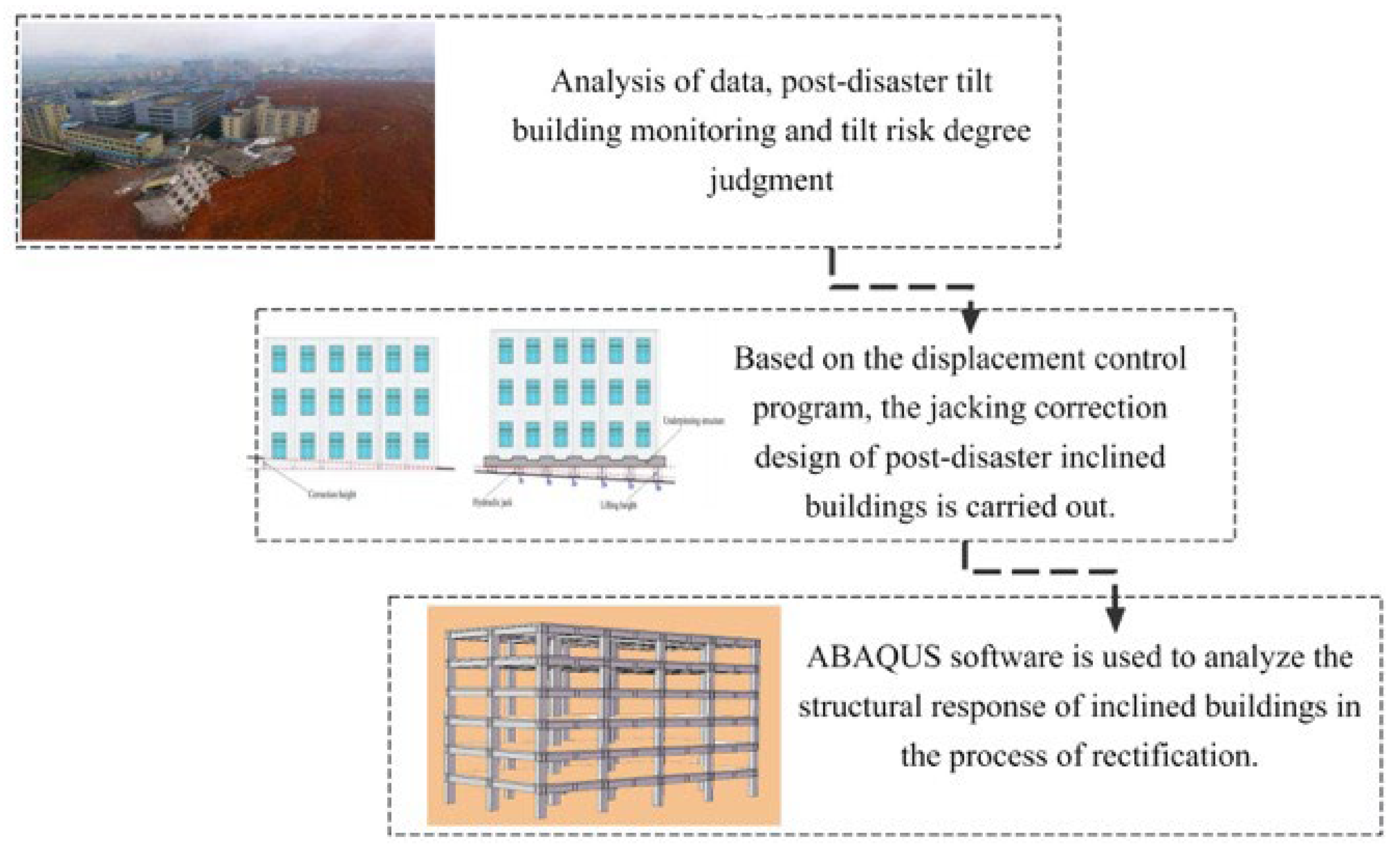
2. Analysis Program
2.1. Subsurface Characteristics
2.2. Geometry and Structural Materials
2.3. Model Establishment
2.3.1. Jacking Correction Design
2.3.2. Lifting Model Establishment
3. Results and Discussion
3.1. Raft Displacement Before and After Lifting Operation
3.2. Position and Force of the Balance Adjustment Device
3.3. Reaction Force Required in the Process of Pile Jacking Reaction Force
3.4. Influence on the Internal Force of Structural Members Before and After Jacking Up
4. Conclusions
- (1)
- Through ABAQUS finite element simulation, the effectiveness of the combined jacking correction technology of micropile and raft foundation was verified. The reasonable arrangement of the pile-raft system can effectively terminate the structural inclination. Applying the jacking force of A-axis 2400 kN, B-axis 2200 kN, and C-axis 1700 kN in stages can gradually correct the inclination. The maximum correction displacement of the A-5-axis column foot was 3.7 mm, and no structural cracking or damage was caused, indicating that the method is both controllable and safe.
- (2)
- During the rectification process, the stress concentration phenomenon was significant, and the maximum stress at the junction of the first-floor A-1 column foot and the top beam of the A-5 column reached 6.5 MPa. The displacement distribution is highly dependent. The top displacement was 105 mm when the deviation was not corrected, and was significantly reduced to 3.7 mm after correction, indicating that high-rise buildings are extremely sensitive to foundation settlement. The displacement analysis of the raft foundation showed that the maximum asymmetric settlement before correction was 47 mm, and the maximum inclination rate was reduced from 0.51% to 0.05%, which is much lower than the allowable value (0.2%) of the specification. This provides a reusable technical template for building correction in soft soil areas. The design of the bearing capacity of 3630 kN is reasonable, which can balance the jacking force and structural load, minimize the settlement difference of each shaft pile, and verify the stability of pile–soil synergy.
- (3)
- Jacking up leads to a significant increase in the axial force of the column. For example, the axial force of the A-5 column increased by 12.9%. The bending moment of beam 2 changed from negative to positive, and the direction and amplitude of the bending moment of the beam changed, indicating that the dynamic redistribution of the internal force of the structure needs to be fully considered in the design stage to avoid the risk of local overload.
- (4)
- Based on the field geotechnical data, a refined finite element model was established, and a phased lifting force application method was proposed. The precise control of the correction process was realized through 20 incremental steps. The micropiles were innovatively combined with the raft foundation to optimize the arrangement of the reaction piles along the column axis, which significantly improved the long-term stability of the correction system. Based on the analysis of the stress cloud and displacement cloud, a real-time monitoring scheme for high-stress areas (such as column foot and beam-column joints) was proposed to form an integrated solution of correction-monitoring-reinforcement.
- (5)
- There is a significant correlation between the arrangement of the micropile-raft system and the long-term stability of the structure. The specific performance is as follows: the stiffness gradient design was adopted along the length direction of the building. The spacing of the A-axis micropiles was set to 2.5 m, and the C-axis was gradually changed to 3.0 m. By matching the settlement distribution characteristics of each axis (the A-axis settlement was large and required higher stiffness support), the long-term creep difference of the structure can be controlled within 0.5 mm/year.
Author Contributions
Funding
Data Availability Statement
Conflicts of Interest
References
- Zhang, X.; Shi, S.; Zhao, H.; Lu, M.; Li, X. Deformation analysis and reinforcement of Jin-gang tower in jacking method. World J. Eng. 2016, 13, 163–168. [Google Scholar] [CrossRef]
- Melnikov, R.; Pronozin, Y.; Stepanova, M.; Bartolomey, L. Soil areas numerical determination aimed at correction of a building tilt. J. Phys. Conf. Ser. 2021, 1928, 012009. [Google Scholar] [CrossRef]
- Chen, H.; Guo, Y.; Alqawzai, S.; Wu, X.; Alnas, S.M. Study on uneven settlement and correction of steel frame structures based on numerical simulation method. PLoS ONE 2024, 19, e0303249. [Google Scholar] [CrossRef] [PubMed]
- Gunay, B.; Hobson, B.W.; Darwazeh, D.; Bursill, J. Estimating energy savings from HVAC controls fault correction through inverse grey box model-based virtual metering. Energy Build. 2023, 282, 112806. [Google Scholar] [CrossRef]
- Stănculescu, I.; Antonescu, I.; Olteanu, A. Straightening of tall structures tilted as a consequence of uneven settlement of foundation soil: Case histories. In Geotechnical Engineering Education and Training; CRC Press: Boca Raton, FL, USA, 2020; pp. 447–454. [Google Scholar]
- Hakro, M.R.; Kumar, A.; Almani, Z.; Ali, M.; Aslam, F.; Fediuk, R.; Klyuev, S.; Klyuev, A.; Sabitov, L. Numerical Analysis of Piled-Raft Foundations on Multi-Layer Soil Considering Settlement and Swelling. Buildings 2022, 12, 356. [Google Scholar] [CrossRef]
- Huang, J.; Yan, J.; Guo, K.; Yang, X.; Peng, S.; Wu, C. Study on the Impact of Deep Foundation Pit Construction on Nearby Elevated Structures—Case Study. Buildings 2024, 14, 2541. [Google Scholar] [CrossRef]
- Khomyakov, V.A.; Shokbarov, Y.M.; Bryantsev, A.A. Experience in handling differential settlements of multi-storey buildings on soft soil. Soil Mech. Found. Eng. 2017, 54, 330–335. [Google Scholar] [CrossRef]
- Jiao, C.; You, S.; Ji, H. Numerical analysis of building structures response under effect of continuous and stepped non-uniform settlement. J. Cent. South Univ. 2023, 30, 4066–4081. [Google Scholar] [CrossRef]
- Shang, H.; Bao, C.; Wang, H.; Ma, X.; Calo, J.; Du, J. Seismic response analysis of frame structures with uneven settlement of foundation considering soil-structure interaction. Results Eng. 2023, 20, 101574. [Google Scholar] [CrossRef]
- El Kamash, W.; El Naggar, H. Improving tilted foundations over soft clay using micropiles: Numerical analysis. Geotech. Geol. Eng. 2023, 41, 2691–2712. [Google Scholar] [CrossRef]
- Soltani-Jigheh, H.; Ehterami, A.A. Numerical investigation of jacking method for asymmetric settlement rectification in tilted concrete buildings. Case Stud. Constr. Mater. 2024, 20, e02710. [Google Scholar] [CrossRef]
- Gromysz, K.; Smolana, M.; Drusa, M. Research on the Characteristics of Jacks Used to Rectify Tilted Buildings. Buildings 2024, 14, 1581. [Google Scholar] [CrossRef]
- Gromysz, K. In situ experimental study on the active support used for building rectification. Materials 2020, 13, 2015. [Google Scholar] [CrossRef] [PubMed]
- Shan, R.; Zhang, X.; Lu, M.; Zhao, H.; Li, X. Numerical Analysis Research of Jacking Method with the Rectification on Steel-Concrete Buildings. Open Civ. Eng. J. 2016, 10, 223–235. [Google Scholar] [CrossRef]
- Fan, J. Research and Engineering Application of Rectification and Reinforcement Technology for Existing High-Rise Buildings in Deep-Filled Loess Sites. Master’s Thesis, Lanzhou University of Technology, Lanzhou, China, 2021. [Google Scholar] [CrossRef]
- Gu, H. Research on The Application of New Rectification Method for Shallow Foundation Buildings in Collapsible Loess Areas. Master’s Thesis, Lanzhou University of Technology, Lanzhou, China, 2024. [Google Scholar] [CrossRef]
- Mi, C. Raft Foundation Rectification Process Mechanism and Simplified Calculation Method. Master’s Thesis, Tianjin University, Tianjin, China, 2021. [Google Scholar] [CrossRef]
- Wang, Q. Research on Deformation Monitoring of the Whole Process of Building Correction with Multi-Source Monitoring Technology. Master’s Thesis, Shandong Jianzhu University, Jinan, China, 2024. [Google Scholar] [CrossRef]
- Li, Y. Numerical Simulation of the Jacking Process of a Steel Structure under Uneven Settlement. Master’s Thesis, Shandong Jianzhu University, Jinan, China, 2023. [Google Scholar]
- Asgari, A.; Bagheri, M.; Hadizadeh, M. Advanced seismic analysis of soil-foundation-structure interaction for shallow and pile foundations in saturated and dry deposits: Insights from 3D parallel finite element modeling. Structures 2024, 69, 107503. [Google Scholar] [CrossRef]
- Bresler, B. Design criteria for reinforced columns under axial load and biaxial bending. J. Proc. 1960, 32, 481–490. [Google Scholar]
- Mroueh, H.; Shahrour, I. A full 3-D finite element analysis of tunneling–adjacent structures interaction. Comput. Geotech. 2003, 30, 245–253. [Google Scholar] [CrossRef]
- Butler, H.; Hoy, H. The Texas Quick Load Test Method for Foundation Load Testing—Users Manual; FHWA IP-77.8, FHWA Implementation Division: Washington, DC, USA, 1977. [Google Scholar]
- Wu, Y.-F.; Liu, T.; Oehlers, D.J. Fundamental principles that govern retrofitting of reinforced concrete columns by steel and FRP jacketing. Adv. Struct. Eng. 2006, 9, 507–533. [Google Scholar] [CrossRef]
- Bagheri, M.; Jamkhaneh, M.E.; Samali, B. Effect of seismic soil–pile–structure interaction on mid-and high-rise steel buildings resting on a group of pile foundations. Int. J. Geomech. 2018, 18, 04018103. [Google Scholar] [CrossRef]


| Soil Classification | Color State | Moisture Content W (%) | Heavy γ (kN/m3) | Dry Weight γd (kN/m3) | Saturation Sr (%) | Porosity Ratio e | Liquid Limit W1 | Plastic Limit Wp | Plasticity Index Ip | Liquidity Index I1 | Coefficient of Collapsibility |
|---|---|---|---|---|---|---|---|---|---|---|---|
| ① Loess-like soil | Brownish-yellow, malleable | 21 | 16.2 | 13.4 | 58 | 0.99 | 29.2 | 17.4 | 11.9 | 0.29 | 0.004 |
| ② Loess-like soil | Brown yellow, plastic~soft plastic | 27.7 | 17.6 | 13.8 | 79 | 0.949 | 32.4 | 18.8 | 13.7 | 0.64 | 0.008 |
| ③ Silty clay | Pinkish yellow, plastic-based, individual hard | 24.1 | 19.1 | 15.4 | 89 | 0.734 | 32.2 | 18.6 | 13.5 | 0.4 | / |
| ④ Silty clay | Light gray, plastic ~hard plastic | 20.3 | 19.9 | 16.6 | 91 | 0.605 | 29.4 | 17.5 | 12 | 0.24 | / |
| ⑤ Coarse sand | Gray yellow, saturated, dense | 21.7 | 19.7 | 16.2 | 92 | 0.641 | 29.3 | 17.4 | 11.9 | 0.37 | / |
| Column Section Size (mm2) | ||||
|---|---|---|---|---|
| Level Number | Axis | 1 | 2–4 | 5 |
| 1 | A | 700 × 700 | 800 × 800 | 700 × 700 |
| B | 800 × 800 | 800 × 800 | 800 × 800 | |
| C | 700 × 700 | 800 × 800 | 700 × 700 | |
| 2 | A | 700 × 700 | 700 × 700 | 700 × 700 |
| B | 800 × 800 | 800 × 800 | 800 × 800 | |
| C | 700 × 700 | 700 × 700 | 700 × 700 | |
| 3 | A | 700 × 700 | 700 × 700 | 700 × 700 |
| B | 700 × 700 | 800 × 800 | 700 × 700 | |
| C | 700 × 700 | 700 × 700 | 700 × 700 | |
| 4 | A | 600 × 600 | 700 × 700 | 600 × 600 |
| B | 600 × 600 | 700 × 700 | 600 × 600 | |
| C | 600 × 600 | 700 × 700 | 600 × 600 | |
| 5–6 | A | 600 × 600 | 600 × 600 | 600 × 600 |
| B | 600 × 600 | 700 × 700 | 600 × 600 | |
| C | 600 × 600 | 600 × 600 | 600 × 600 | |
| Beam section size | 400 × 700 | |||
| Axis | Maximum Settlement (mm) | Lifting Force Required for Each Stage (kN) | Total Required Lifting Force (kN) |
|---|---|---|---|
| A | −90.1 | 120 | 2400 |
| B | −70.9 | 110 | 2200 |
| C | −53.2 | 85 | 1700 |
Disclaimer/Publisher’s Note: The statements, opinions and data contained in all publications are solely those of the individual author(s) and contributor(s) and not of MDPI and/or the editor(s). MDPI and/or the editor(s) disclaim responsibility for any injury to people or property resulting from any ideas, methods, instructions or products referred to in the content. |
© 2025 by the authors. Licensee MDPI, Basel, Switzerland. This article is an open access article distributed under the terms and conditions of the Creative Commons Attribution (CC BY) license (https://creativecommons.org/licenses/by/4.0/).
Share and Cite
Xie, M.; Yin, L.; Wang, Z.; Xu, F.; Wu, X.; Xu, M. Numerical Simulation and Analysis of Micropile-Raft Joint Jacking Technology for Rectifying Inclined Buildings Due to Uneven Settlement. Buildings 2025, 15, 2485. https://doi.org/10.3390/buildings15142485
Xie M, Yin L, Wang Z, Xu F, Wu X, Xu M. Numerical Simulation and Analysis of Micropile-Raft Joint Jacking Technology for Rectifying Inclined Buildings Due to Uneven Settlement. Buildings. 2025; 15(14):2485. https://doi.org/10.3390/buildings15142485
Chicago/Turabian StyleXie, Ming, Li’e Yin, Zhangdong Wang, Fangbo Xu, Xiangdong Wu, and Mengqi Xu. 2025. "Numerical Simulation and Analysis of Micropile-Raft Joint Jacking Technology for Rectifying Inclined Buildings Due to Uneven Settlement" Buildings 15, no. 14: 2485. https://doi.org/10.3390/buildings15142485
APA StyleXie, M., Yin, L., Wang, Z., Xu, F., Wu, X., & Xu, M. (2025). Numerical Simulation and Analysis of Micropile-Raft Joint Jacking Technology for Rectifying Inclined Buildings Due to Uneven Settlement. Buildings, 15(14), 2485. https://doi.org/10.3390/buildings15142485